JP6869375B2 - Single catheter electrode tissue cutting system for creating anastomosis - Google Patents
Single catheter electrode tissue cutting system for creating anastomosis Download PDFInfo
- Publication number
- JP6869375B2 JP6869375B2 JP2019559313A JP2019559313A JP6869375B2 JP 6869375 B2 JP6869375 B2 JP 6869375B2 JP 2019559313 A JP2019559313 A JP 2019559313A JP 2019559313 A JP2019559313 A JP 2019559313A JP 6869375 B2 JP6869375 B2 JP 6869375B2
- Authority
- JP
- Japan
- Prior art keywords
- catheter
- cutting system
- electrode
- tissue cutting
- tissue
- Prior art date
- Legal status (The legal status is an assumption and is not a legal conclusion. Google has not performed a legal analysis and makes no representation as to the accuracy of the status listed.)
- Active
Links
- 238000005520 cutting process Methods 0.000 title claims description 116
- 230000003872 anastomosis Effects 0.000 title claims description 31
- 210000003484 anatomy Anatomy 0.000 claims description 50
- 210000003462 vein Anatomy 0.000 claims description 40
- 210000001367 artery Anatomy 0.000 claims description 39
- 210000004204 blood vessel Anatomy 0.000 claims description 29
- 230000007246 mechanism Effects 0.000 claims description 15
- 239000012212 insulator Substances 0.000 claims description 10
- 239000004952 Polyamide Substances 0.000 claims description 8
- 229920002647 polyamide Polymers 0.000 claims description 8
- 229910001000 nickel titanium Inorganic materials 0.000 claims description 6
- 229910001220 stainless steel Inorganic materials 0.000 claims description 6
- 239000010935 stainless steel Substances 0.000 claims description 6
- 239000003550 marker Substances 0.000 claims description 5
- 239000000463 material Substances 0.000 claims description 5
- 229910001120 nichrome Inorganic materials 0.000 claims description 5
- HLXZNVUGXRDIFK-UHFFFAOYSA-N nickel titanium Chemical compound [Ti].[Ti].[Ti].[Ti].[Ti].[Ti].[Ti].[Ti].[Ti].[Ti].[Ti].[Ni].[Ni].[Ni].[Ni].[Ni].[Ni].[Ni].[Ni].[Ni].[Ni].[Ni].[Ni].[Ni].[Ni] HLXZNVUGXRDIFK-UHFFFAOYSA-N 0.000 claims description 5
- 230000005855 radiation Effects 0.000 claims description 5
- 238000000034 method Methods 0.000 description 17
- 206010016717 Fistula Diseases 0.000 description 12
- 230000003890 fistula Effects 0.000 description 12
- 239000008280 blood Substances 0.000 description 8
- 210000004369 blood Anatomy 0.000 description 8
- 230000002792 vascular Effects 0.000 description 6
- 238000001631 haemodialysis Methods 0.000 description 4
- 230000000322 hemodialysis Effects 0.000 description 4
- 230000004807 localization Effects 0.000 description 4
- 230000017531 blood circulation Effects 0.000 description 3
- 210000003813 thumb Anatomy 0.000 description 3
- 206010003226 Arteriovenous fistula Diseases 0.000 description 2
- CURLTUGMZLYLDI-UHFFFAOYSA-N Carbon dioxide Chemical compound O=C=O CURLTUGMZLYLDI-UHFFFAOYSA-N 0.000 description 2
- 238000013459 approach Methods 0.000 description 2
- 230000004087 circulation Effects 0.000 description 2
- 238000011161 development Methods 0.000 description 2
- 238000000502 dialysis Methods 0.000 description 2
- 235000015097 nutrients Nutrition 0.000 description 2
- 239000004642 Polyimide Substances 0.000 description 1
- 208000001647 Renal Insufficiency Diseases 0.000 description 1
- 230000004913 activation Effects 0.000 description 1
- 210000000436 anus Anatomy 0.000 description 1
- 210000000941 bile Anatomy 0.000 description 1
- 210000000013 bile duct Anatomy 0.000 description 1
- 210000001736 capillary Anatomy 0.000 description 1
- 229910002092 carbon dioxide Inorganic materials 0.000 description 1
- 239000001569 carbon dioxide Substances 0.000 description 1
- 238000002512 chemotherapy Methods 0.000 description 1
- 238000002788 crimping Methods 0.000 description 1
- 238000010586 diagram Methods 0.000 description 1
- 238000002224 dissection Methods 0.000 description 1
- 238000010494 dissociation reaction Methods 0.000 description 1
- 230000005593 dissociations Effects 0.000 description 1
- 210000001198 duodenum Anatomy 0.000 description 1
- 239000012530 fluid Substances 0.000 description 1
- 210000000245 forearm Anatomy 0.000 description 1
- 238000010438 heat treatment Methods 0.000 description 1
- 210000000936 intestine Anatomy 0.000 description 1
- 210000003734 kidney Anatomy 0.000 description 1
- 201000006370 kidney failure Diseases 0.000 description 1
- 210000004185 liver Anatomy 0.000 description 1
- 238000004519 manufacturing process Methods 0.000 description 1
- 230000004048 modification Effects 0.000 description 1
- 238000012986 modification Methods 0.000 description 1
- 210000000056 organ Anatomy 0.000 description 1
- 229920001721 polyimide Polymers 0.000 description 1
- 230000008569 process Effects 0.000 description 1
- 238000012545 processing Methods 0.000 description 1
- 238000000926 separation method Methods 0.000 description 1
- 238000001356 surgical procedure Methods 0.000 description 1
- 210000000689 upper leg Anatomy 0.000 description 1
- 210000000626 ureter Anatomy 0.000 description 1
- 210000002700 urine Anatomy 0.000 description 1
Images
Classifications
-
- A—HUMAN NECESSITIES
- A61—MEDICAL OR VETERINARY SCIENCE; HYGIENE
- A61B—DIAGNOSIS; SURGERY; IDENTIFICATION
- A61B18/00—Surgical instruments, devices or methods for transferring non-mechanical forms of energy to or from the body
- A61B18/04—Surgical instruments, devices or methods for transferring non-mechanical forms of energy to or from the body by heating
- A61B18/12—Surgical instruments, devices or methods for transferring non-mechanical forms of energy to or from the body by heating by passing a current through the tissue to be heated, e.g. high-frequency current
- A61B18/14—Probes or electrodes therefor
- A61B18/1492—Probes or electrodes therefor having a flexible, catheter-like structure, e.g. for heart ablation
-
- A—HUMAN NECESSITIES
- A61—MEDICAL OR VETERINARY SCIENCE; HYGIENE
- A61B—DIAGNOSIS; SURGERY; IDENTIFICATION
- A61B17/00—Surgical instruments, devices or methods, e.g. tourniquets
- A61B17/32—Surgical cutting instruments
- A61B17/320068—Surgical cutting instruments using mechanical vibrations, e.g. ultrasonic
-
- A—HUMAN NECESSITIES
- A61—MEDICAL OR VETERINARY SCIENCE; HYGIENE
- A61B—DIAGNOSIS; SURGERY; IDENTIFICATION
- A61B18/00—Surgical instruments, devices or methods for transferring non-mechanical forms of energy to or from the body
- A61B18/04—Surgical instruments, devices or methods for transferring non-mechanical forms of energy to or from the body by heating
- A61B18/08—Surgical instruments, devices or methods for transferring non-mechanical forms of energy to or from the body by heating by means of electrically-heated probes
- A61B18/082—Probes or electrodes therefor
-
- A—HUMAN NECESSITIES
- A61—MEDICAL OR VETERINARY SCIENCE; HYGIENE
- A61B—DIAGNOSIS; SURGERY; IDENTIFICATION
- A61B18/00—Surgical instruments, devices or methods for transferring non-mechanical forms of energy to or from the body
- A61B18/04—Surgical instruments, devices or methods for transferring non-mechanical forms of energy to or from the body by heating
- A61B18/12—Surgical instruments, devices or methods for transferring non-mechanical forms of energy to or from the body by heating by passing a current through the tissue to be heated, e.g. high-frequency current
- A61B18/14—Probes or electrodes therefor
-
- A—HUMAN NECESSITIES
- A61—MEDICAL OR VETERINARY SCIENCE; HYGIENE
- A61M—DEVICES FOR INTRODUCING MEDIA INTO, OR ONTO, THE BODY; DEVICES FOR TRANSDUCING BODY MEDIA OR FOR TAKING MEDIA FROM THE BODY; DEVICES FOR PRODUCING OR ENDING SLEEP OR STUPOR
- A61M25/00—Catheters; Hollow probes
- A61M25/0067—Catheters; Hollow probes characterised by the distal end, e.g. tips
- A61M25/0068—Static characteristics of the catheter tip, e.g. shape, atraumatic tip, curved tip or tip structure
-
- A—HUMAN NECESSITIES
- A61—MEDICAL OR VETERINARY SCIENCE; HYGIENE
- A61M—DEVICES FOR INTRODUCING MEDIA INTO, OR ONTO, THE BODY; DEVICES FOR TRANSDUCING BODY MEDIA OR FOR TAKING MEDIA FROM THE BODY; DEVICES FOR PRODUCING OR ENDING SLEEP OR STUPOR
- A61M25/00—Catheters; Hollow probes
- A61M25/0067—Catheters; Hollow probes characterised by the distal end, e.g. tips
- A61M25/0082—Catheter tip comprising a tool
-
- A—HUMAN NECESSITIES
- A61—MEDICAL OR VETERINARY SCIENCE; HYGIENE
- A61M—DEVICES FOR INTRODUCING MEDIA INTO, OR ONTO, THE BODY; DEVICES FOR TRANSDUCING BODY MEDIA OR FOR TAKING MEDIA FROM THE BODY; DEVICES FOR PRODUCING OR ENDING SLEEP OR STUPOR
- A61M25/00—Catheters; Hollow probes
- A61M25/01—Introducing, guiding, advancing, emplacing or holding catheters
- A61M25/0105—Steering means as part of the catheter or advancing means; Markers for positioning
- A61M25/0108—Steering means as part of the catheter or advancing means; Markers for positioning using radio-opaque or ultrasound markers
-
- A—HUMAN NECESSITIES
- A61—MEDICAL OR VETERINARY SCIENCE; HYGIENE
- A61M—DEVICES FOR INTRODUCING MEDIA INTO, OR ONTO, THE BODY; DEVICES FOR TRANSDUCING BODY MEDIA OR FOR TAKING MEDIA FROM THE BODY; DEVICES FOR PRODUCING OR ENDING SLEEP OR STUPOR
- A61M25/00—Catheters; Hollow probes
- A61M25/01—Introducing, guiding, advancing, emplacing or holding catheters
- A61M25/06—Body-piercing guide needles or the like
- A61M25/065—Guide needles
-
- A—HUMAN NECESSITIES
- A61—MEDICAL OR VETERINARY SCIENCE; HYGIENE
- A61B—DIAGNOSIS; SURGERY; IDENTIFICATION
- A61B17/00—Surgical instruments, devices or methods, e.g. tourniquets
- A61B17/11—Surgical instruments, devices or methods, e.g. tourniquets for performing anastomosis; Buttons for anastomosis
-
- A—HUMAN NECESSITIES
- A61—MEDICAL OR VETERINARY SCIENCE; HYGIENE
- A61B—DIAGNOSIS; SURGERY; IDENTIFICATION
- A61B17/00—Surgical instruments, devices or methods, e.g. tourniquets
- A61B2017/00831—Material properties
- A61B2017/00867—Material properties shape memory effect
-
- A—HUMAN NECESSITIES
- A61—MEDICAL OR VETERINARY SCIENCE; HYGIENE
- A61B—DIAGNOSIS; SURGERY; IDENTIFICATION
- A61B17/00—Surgical instruments, devices or methods, e.g. tourniquets
- A61B17/11—Surgical instruments, devices or methods, e.g. tourniquets for performing anastomosis; Buttons for anastomosis
- A61B2017/1107—Surgical instruments, devices or methods, e.g. tourniquets for performing anastomosis; Buttons for anastomosis for blood vessels
-
- A—HUMAN NECESSITIES
- A61—MEDICAL OR VETERINARY SCIENCE; HYGIENE
- A61B—DIAGNOSIS; SURGERY; IDENTIFICATION
- A61B17/00—Surgical instruments, devices or methods, e.g. tourniquets
- A61B17/11—Surgical instruments, devices or methods, e.g. tourniquets for performing anastomosis; Buttons for anastomosis
- A61B2017/1139—Side-to-side connections, e.g. shunt or X-connections
-
- A—HUMAN NECESSITIES
- A61—MEDICAL OR VETERINARY SCIENCE; HYGIENE
- A61B—DIAGNOSIS; SURGERY; IDENTIFICATION
- A61B18/00—Surgical instruments, devices or methods for transferring non-mechanical forms of energy to or from the body
- A61B2018/00315—Surgical instruments, devices or methods for transferring non-mechanical forms of energy to or from the body for treatment of particular body parts
- A61B2018/00345—Vascular system
- A61B2018/00404—Blood vessels other than those in or around the heart
-
- A—HUMAN NECESSITIES
- A61—MEDICAL OR VETERINARY SCIENCE; HYGIENE
- A61B—DIAGNOSIS; SURGERY; IDENTIFICATION
- A61B18/00—Surgical instruments, devices or methods for transferring non-mechanical forms of energy to or from the body
- A61B2018/00571—Surgical instruments, devices or methods for transferring non-mechanical forms of energy to or from the body for achieving a particular surgical effect
- A61B2018/00601—Cutting
-
- A—HUMAN NECESSITIES
- A61—MEDICAL OR VETERINARY SCIENCE; HYGIENE
- A61B—DIAGNOSIS; SURGERY; IDENTIFICATION
- A61B18/00—Surgical instruments, devices or methods for transferring non-mechanical forms of energy to or from the body
- A61B18/04—Surgical instruments, devices or methods for transferring non-mechanical forms of energy to or from the body by heating
- A61B18/12—Surgical instruments, devices or methods for transferring non-mechanical forms of energy to or from the body by heating by passing a current through the tissue to be heated, e.g. high-frequency current
- A61B18/14—Probes or electrodes therefor
- A61B2018/1405—Electrodes having a specific shape
- A61B2018/144—Wire
-
- A—HUMAN NECESSITIES
- A61—MEDICAL OR VETERINARY SCIENCE; HYGIENE
- A61B—DIAGNOSIS; SURGERY; IDENTIFICATION
- A61B18/00—Surgical instruments, devices or methods for transferring non-mechanical forms of energy to or from the body
- A61B18/04—Surgical instruments, devices or methods for transferring non-mechanical forms of energy to or from the body by heating
- A61B18/12—Surgical instruments, devices or methods for transferring non-mechanical forms of energy to or from the body by heating by passing a current through the tissue to be heated, e.g. high-frequency current
- A61B18/14—Probes or electrodes therefor
- A61B2018/1475—Electrodes retractable in or deployable from a housing
-
- A—HUMAN NECESSITIES
- A61—MEDICAL OR VETERINARY SCIENCE; HYGIENE
- A61B—DIAGNOSIS; SURGERY; IDENTIFICATION
- A61B90/00—Instruments, implements or accessories specially adapted for surgery or diagnosis and not covered by any of the groups A61B1/00 - A61B50/00, e.g. for luxation treatment or for protecting wound edges
- A61B90/39—Markers, e.g. radio-opaque or breast lesions markers
- A61B2090/3966—Radiopaque markers visible in an X-ray image
-
- A—HUMAN NECESSITIES
- A61—MEDICAL OR VETERINARY SCIENCE; HYGIENE
- A61M—DEVICES FOR INTRODUCING MEDIA INTO, OR ONTO, THE BODY; DEVICES FOR TRANSDUCING BODY MEDIA OR FOR TAKING MEDIA FROM THE BODY; DEVICES FOR PRODUCING OR ENDING SLEEP OR STUPOR
- A61M25/00—Catheters; Hollow probes
- A61M25/01—Introducing, guiding, advancing, emplacing or holding catheters
- A61M25/0105—Steering means as part of the catheter or advancing means; Markers for positioning
- A61M2025/0166—Sensors, electrodes or the like for guiding the catheter to a target zone, e.g. image guided or magnetically guided
-
- A—HUMAN NECESSITIES
- A61—MEDICAL OR VETERINARY SCIENCE; HYGIENE
- A61M—DEVICES FOR INTRODUCING MEDIA INTO, OR ONTO, THE BODY; DEVICES FOR TRANSDUCING BODY MEDIA OR FOR TAKING MEDIA FROM THE BODY; DEVICES FOR PRODUCING OR ENDING SLEEP OR STUPOR
- A61M2205/00—General characteristics of the apparatus
- A61M2205/32—General characteristics of the apparatus with radio-opaque indicia
-
- A—HUMAN NECESSITIES
- A61—MEDICAL OR VETERINARY SCIENCE; HYGIENE
- A61M—DEVICES FOR INTRODUCING MEDIA INTO, OR ONTO, THE BODY; DEVICES FOR TRANSDUCING BODY MEDIA OR FOR TAKING MEDIA FROM THE BODY; DEVICES FOR PRODUCING OR ENDING SLEEP OR STUPOR
- A61M2205/00—General characteristics of the apparatus
- A61M2205/33—Controlling, regulating or measuring
- A61M2205/3331—Pressure; Flow
-
- A—HUMAN NECESSITIES
- A61—MEDICAL OR VETERINARY SCIENCE; HYGIENE
- A61M—DEVICES FOR INTRODUCING MEDIA INTO, OR ONTO, THE BODY; DEVICES FOR TRANSDUCING BODY MEDIA OR FOR TAKING MEDIA FROM THE BODY; DEVICES FOR PRODUCING OR ENDING SLEEP OR STUPOR
- A61M2210/00—Anatomical parts of the body
- A61M2210/12—Blood circulatory system
-
- A—HUMAN NECESSITIES
- A61—MEDICAL OR VETERINARY SCIENCE; HYGIENE
- A61M—DEVICES FOR INTRODUCING MEDIA INTO, OR ONTO, THE BODY; DEVICES FOR TRANSDUCING BODY MEDIA OR FOR TAKING MEDIA FROM THE BODY; DEVICES FOR PRODUCING OR ENDING SLEEP OR STUPOR
- A61M25/00—Catheters; Hollow probes
- A61M25/01—Introducing, guiding, advancing, emplacing or holding catheters
- A61M25/09—Guide wires
-
- A—HUMAN NECESSITIES
- A61—MEDICAL OR VETERINARY SCIENCE; HYGIENE
- A61M—DEVICES FOR INTRODUCING MEDIA INTO, OR ONTO, THE BODY; DEVICES FOR TRANSDUCING BODY MEDIA OR FOR TAKING MEDIA FROM THE BODY; DEVICES FOR PRODUCING OR ENDING SLEEP OR STUPOR
- A61M29/00—Dilators with or without means for introducing media, e.g. remedies
Landscapes
- Health & Medical Sciences (AREA)
- Life Sciences & Earth Sciences (AREA)
- Engineering & Computer Science (AREA)
- Veterinary Medicine (AREA)
- General Health & Medical Sciences (AREA)
- Biomedical Technology (AREA)
- Heart & Thoracic Surgery (AREA)
- Public Health (AREA)
- Animal Behavior & Ethology (AREA)
- Surgery (AREA)
- Pulmonology (AREA)
- Biophysics (AREA)
- Anesthesiology (AREA)
- Hematology (AREA)
- Molecular Biology (AREA)
- Medical Informatics (AREA)
- Nuclear Medicine, Radiotherapy & Molecular Imaging (AREA)
- Otolaryngology (AREA)
- Plasma & Fusion (AREA)
- Physics & Mathematics (AREA)
- Cardiology (AREA)
- Dentistry (AREA)
- Mechanical Engineering (AREA)
- Surgical Instruments (AREA)
- Media Introduction/Drainage Providing Device (AREA)
Description
体内には様々な流動体が導管を通して組織の隅々まで運ばれ、種々の基本機能を実行している。血管、動脈、静脈、及び毛管は血液を身体の隅々まで運び、栄養素及び排泄物を別の器官及び組織に送って処理させる。胆管は胆汁を肝臓から十二指腸に輸送する。尿管は尿を腎臓から膀胱に送る。腸は栄養素及び排泄物を口から肛門に運ぶ。 Various fluids are carried into the body through conduits to every corner of the tissue and perform various basic functions. Blood vessels, arteries, veins, and capillaries carry blood to every corner of the body, sending nutrients and excrement to other organs and tissues for processing. The bile ducts transport bile from the liver to the duodenum. The ureter sends urine from the kidneys to the bladder. The intestines carry nutrients and excrement from the mouth to the anus.
診療において、導管を他の導管に接続するか代替導管に接続して病気や機能不全に陥った既存の導管を処置する必要が生じることがままある。導管の間に形成される接続は吻合と呼ばれる。 In practice, it may be necessary to connect a conduit to another or an alternative conduit to treat an existing sick or dysfunctional conduit. The connections formed between the conduits are called anastomosis.
血管では、吻合は静脈と動脈との間、動脈と動脈との間、または静脈と静脈との間に作成される。これらの接続の目的は、動脈と血管の間に高流量接続や瘻を作成すること、或いは代替導管の障害物の周りやバイパスに血液を送ることである。バイパスのための前記導管は血管、動脈、または補綴用グラフトである。 In blood vessels, anastomosis is created between veins and arteries, between arteries, or between veins. The purpose of these connections is to create high flow connections or fistulas between arteries and blood vessels, or to pump blood around or bypassing obstacles in alternative conduits. The conduit for bypass is a blood vessel, artery, or prosthetic graft.
吻合は手術中に2つの脈管や導管を1つに直接接続することで形成される。前記脈管は縫合糸やクリップにより接合される。前記吻合は端端、端側、または惻々吻合である。血管では、前記吻合は楕円形状を呈し、手で連続縫合されるのが最も一般的である。吻合作成の他の方法として炭酸ガスレーザーを含み、種々の接続用補綴具、クリップ、ステントを使用する様々な方法が存在する。 Anastomosis is formed by connecting two vessels or conduits directly into one during surgery. The vessels are joined by sutures and clips. The anastomosis is end-to-end, end-to-end, or end-to-end. In blood vessels, the anastomosis has an elliptical shape and is most commonly sutured continuously by hand. Other methods of anastomotic production include carbon dioxide lasers and there are various methods using various connecting prostheses, clips and stents.
動静脈瘻(AVF)は動脈と血管とを接続することで形成される。この種の接続は血液透析に用いられ、運動耐性を高め、動脈や静脈を開いた状態に維持させ、化学療法のための信頼性の高いアクセスを提供する。 An arteriovenous fistula (AVF) is formed by connecting arteries and blood vessels. This type of connection is used in hemodialysis to increase exercise tolerance, keep arteries and veins open, and provide reliable access for chemotherapy.
このほか、補綴用グラフトを動脈から血管に接続し、同様に動脈と静脈との間に高流量の接続を作成する方法もある。これは動静脈グラフトと呼ばれ、2つの吻合が必要となる。1つは動脈とグラフトとのの間に作成され、もう1つはグラフトと静脈との間に作成される。 Another method is to connect the prosthetic graft from the artery to the blood vessel and similarly create a high flow connection between the artery and vein. This is called an arteriovenous graft and requires two anastomosis. One is created between the artery and the graft and the other is created between the graft and the vein.
バイパスは動静脈グラフトと相似する。障害物を迂回させるために2つの吻合及び導管が必要となる。血管から導管に近位吻合が形成される。前記導管は前記障害物の周りを延伸させ、第二遠位吻合が前記導管と脈管との間に前記障害物を越えるように形成される。 Bypass is similar to an arteriovenous graft. Two anastomosis and ducts are needed to bypass the obstacle. A proximal anastomosis is formed from the blood vessel to the conduit. The conduit extends around the obstacle and a second distal anastomosis is formed between the conduit and the vessel so as to cross the obstacle.
上述のように、近年の診療では、血液透析のために動脈と静脈とを接続して瘻を作成することが求められている。血液透析のプロセスでは、血液を体内から素早く抜いて、前記血液に透析装置を通過させて体内に戻す必要がある。前記血液循環へのアクセスは、(1)大静脈に配置されるカテーテル、(2)動脈及び血管に装着される補綴用グラフト、または(3)動脈が静脈に直接接合される瘻、により達成される。 As described above, in recent medical practice, it is required to connect arteries and veins to create a fistula for hemodialysis. In the process of hemodialysis, it is necessary to quickly remove blood from the body and allow the blood to pass through a dialysis machine and return to the body. Access to the blood circulation is achieved by (1) a catheter placed in the vena cava, (2) a prosthetic graft attached to an artery and blood vessel, or (3) a fistula in which the artery is directly attached to the vein. To.
腎不全の患者にとっては血液透析が必要となる。自家血管を使用した瘻は高い血流量を実現するため1つの手段である。前記瘻は、血液を体内から抽出して透析装置に流入させ、排泄物を除去した後に体内に戻すことが可能な高い血流量を提供する。前記血液は前記動脈付近の大型アクセス針を通して抽出され、第二大型回流針を通して前記瘻に戻される。これらの瘻は通常前腕か上腕に作成され、大腿に作成されることは少なく、その他の身体の部位に作成されることは稀である。大事な点は、前記瘻は毎分500ml以上の流量を達成可能であり、静脈を成熟または成長させることができる点である。静脈は成熟すると4mm超に達し、大型針でアクセス可能となる。前記アクセス針及び回流針を確実に分離し、前記瘻に挿入された前記針の間を透析済みの血液と未透析の血液とが再循環するのを防止するために、前記瘻が作成される静脈の部位には十分な長さ(6cm超)が必要である。 Hemodialysis is required for patients with renal failure. Fistulas using autologous blood vessels are one means of achieving high blood flow. The fistula provides a high blood flow that allows blood to be extracted from the body and into the dialysis machine to remove excrement and then return to the body. The blood is extracted through a large access needle near the artery and returned to the fistula through a second large circulation needle. These fistulas are usually created on the forearm or upper arm, rarely on the thighs, and rarely on other parts of the body. The important point is that the fistula can achieve a flow rate of 500 ml or more per minute and can mature or grow veins. When the vein matures, it reaches over 4 mm and is accessible with a large needle. The fistula is created to ensure separation of the access needle and circulation needle and to prevent recirculation of dialyzed and undialyzed blood between the needles inserted into the fistula. The site of the vein needs to be long enough (> 6 cm).
瘻は麻酔下の患者の動脈及び静脈を周辺の組織から慎重に解離させ、前記脈管を細い縫合糸やクリップで縫い合わせることで作成される。これにより、吻合に接続が作成される。前記吻合は素早く正確に作成し、解離を少なくし、痛みを少なくすることが強く求められている。前記吻合は正しい大きさでスムーズに作成し、前記動脈と静脈とが絡まないようにすることが重要である。 A fistula is created by carefully dissociating the anesthetized patient's arteries and veins from the surrounding tissue and stitching the vessels together with a thin suture or clip. This creates a connection in the anastomosis. There is a strong need to create the anastomosis quickly and accurately, reduce dissociation, and reduce pain. It is important that the anastomosis is of the correct size and is made smoothly so that the arteries and veins are not entangled.
本発明に係るカテーテル及び組織切断システムは、第一解剖学的構造及び第二解剖学的構造の間に吻合を経皮的に作成する。前記システムはルーメン及び先細遠隔端で構成される本体を有するカテーテルを備え、第一ガイドワイヤにより前記第一解剖学的構造に遠位に移動する。切断電極は第二ガイドワイヤに追随するルーメンと共に前記本体に格納され、前記第二解剖学的構造に挿入可能である。エネルギー供給は、組織壁を切断して前記第一解剖学的構造を定義するために前記切断電極にエネルギーを供給するために操作される。使用方法の例では、前記第一解剖学的構造及び前記第二解剖学的構造は静脈及び動脈等の隣接血管を含む。 The catheter and tissue cutting system according to the present invention creates an anastomosis percutaneously between the first and second anatomical structures. The system comprises a catheter with a body consisting of a lumen and a tapered remote end, which is moved distally to the first anatomy by a first guide wire. The cutting electrode is housed in the body together with a lumen that follows the second guide wire and can be inserted into the second anatomy. The energy supply is manipulated to supply energy to the cutting electrode to cut the tissue wall and define the first anatomy. In the usage example, the first anatomical structure and the second anatomical structure include adjacent blood vessels such as veins and arteries.
上述の前記システムはインナールーメンを有する同軸穿刺部材を更に備え、前記同軸穿刺部材は前記本体に対して遠位に移動を行うと共に前記第一解剖学的構造の壁を穿刺させて前記第二解剖学的構造に進入する。前記第一解剖学的構造に遠位に前進する第一ガイドワイヤが提供され、前記穿刺部材の前記インナールーメンにより第二ガイドワイヤが配置されて患者の体内にガイドレールが形成され、前記第一解剖学的構造を通過させて前記第二解剖学的構造に進入する。前記穿刺部材は前記本体ルーメンに退縮される。
前記第一ガイドワイヤは前記本体ルーメンから遠位に延出され、前記カテーテル本体が遠位に追随して前記第一解剖学的構造に進入する。前記第二ガイドワイヤは、前記第一解剖学的構造から前記第二解剖学的構造に進入し、前記切断電極から遠位に延出され、前記切断電極が前記本体から分離して前記隣接解剖学的構造に進入する。前記切断電極はばね荷重等により弾性的に偏向すると共に、前記第二解剖学的構造に前進する際に前記解剖学的構造の壁の間に対して圧力をかける。図示する実施形態では、前記切断電極は前記本体のサイドポートから前記本体に出し入れされる。
The system described above further comprises a coaxial puncture member having an inner lumen, the coaxial puncture member moving distal to the body and puncturing the wall of the first anatomical structure to dissect the second anatomy. Enter the anatomy. The first anatomical structure is provided with a first guide wire that advances distally, the inner lumen of the puncture member displaces the second guide wire to form a guide rail within the patient's body, said first. It passes through the anatomical structure and enters the second anatomical structure. The puncture member retracts into the body lumen.
The first guide wire extends distally from the body lumen and the catheter body follows distally into the first anatomy. The second guide wire enters the second anatomical structure from the first anatomical structure and extends distally from the cutting electrode, and the cutting electrode is separated from the main body and the adjacent dissection. Enter the anatomy. The cutting electrode is elastically deflected by a spring load or the like, and pressure is applied between the walls of the anatomical structure when advancing to the second anatomical structure. In the illustrated embodiment, the cutting electrode is taken in and out of the main body from the side port of the main body.
前記切断電極はステンレス鋼、ニチノール、またはニクロムのうちの1つを含む。前記エネルギー供給は高周波、超音波、または抵抗熱エネルギーを前記切断電極に供給する。幾つかの実施形態では、前記穿刺部材は微細穿刺針を備える。幾つかの実施形態では、前記切断電極が切断ワイヤを備える。図示する方法では、前記第一解剖学的構造は静脈であり、前記第二解剖学的構造は動脈である。前記切断ワイヤはポリアミド絶縁体を含み、前記切断電極は端前記ポリアミド絶縁体部分の遠隔に配置される。 The cutting electrode comprises one of stainless steel, nitinol, or nichrome. The energy supply supplies high frequency, ultrasonic, or resistance thermal energy to the cutting electrode. In some embodiments, the puncture member comprises a fine puncture needle. In some embodiments, the cutting electrode comprises a cutting wire. In the illustrated method, the first anatomical structure is a vein and the second anatomical structure is an artery. The cutting wire comprises a polyamide insulator, and the cutting electrode is located distantly from the polyamide insulator portion at the end.
位置決め機構は前記本体に配置され、前記電極が前記第二解剖学的構造に進入した際に検出を行う。前記位置決め機構は圧力センサー、放射線不透過マーカー、またはブリードポートのうちの1つを備える。 The positioning mechanism is arranged in the main body and detects when the electrode enters the second anatomical structure. The positioning mechanism comprises one of a pressure sensor, a radiation opaque marker, or a bleed port.
本発明の他の特徴は、血管内アクセスを作成し、ガイドワイヤを留置するためのカテーテル及び組織切断システムを提供することにある。前記システムは組織に遠位に移動すると共に遠位に移動する際に組織を穿刺させる穿刺部材を備え、カテーテルは、前記穿刺部材により作成された開口部を通して血管に遠位に移動するルーメンを有する本体を備え、切断電極は前記本体ルーメンに配置可能であり、且つ前記本体ルーメンにより前記血管遠位に挿入されるか隣接血管に近接される。アクチュエータは、前記切断電極の出し入れ操作に用いられる。エネルギー供給は組織壁を切断して前記血管を定義するための前記切断電極にエネルギーを供給する。 Another feature of the present invention is to provide a catheter and tissue cutting system for creating intravascular access and placing guidewires. The system comprises a puncture member that moves distally to the tissue and punctures the tissue as it moves distally, and the catheter has a lumen that moves distally to the blood vessel through an opening created by the puncture member. It comprises a body, the cutting electrode can be placed in the body lumen, and is inserted distal to or close to the adjacent vessel by the body lumen. The actuator is used for the operation of inserting and removing the cutting electrode. The energy supply cuts the tissue wall and supplies energy to the cutting electrode for defining the blood vessel.
第一ガイドワイヤは前記本体ルーメンから遠位に延出され、前記カテーテル本体が遠位に追随して前記血管に進入する。第二ガイドワイヤは前記切断電極から遠位に延出され、前記切断電極が前記本体から遠位に延出される。前記切断電極はばね荷重等により弾性的に偏向すると共に前記本体に完全に退縮される。前記切断電極は前記本体のサイドポートを介して前記本体から出入可能である。 The first guide wire extends distally from the body lumen and the catheter body follows distally into the blood vessel. The second guide wire extends distally from the cutting electrode, and the cutting electrode extends distally from the body. The cutting electrode is elastically deflected by a spring load or the like and is completely retracted to the main body. The cutting electrode can be taken in and out of the main body through the side port of the main body.
前記切断電極は1つステンレス鋼、ニチノール、またはニクロムのうちの1つを含む。前記エネルギー供給は高周波、超音波、または抵抗熱エネルギーを前記切断電極に供給する。幾つかの実施形態では、前記穿刺部材は微細穿刺針を備える。幾つかの実施形態では、前記切断電極はポリアミド絶縁体を含む切断ワイヤを備え、前記切断電極が端前記ポリアミド絶縁体部分の遠隔に配置される。 The cutting electrode comprises one of stainless steel, nitinol, or nichrome. The energy supply supplies high frequency, ultrasonic, or resistance thermal energy to the cutting electrode. In some embodiments, the puncture member comprises a fine puncture needle. In some embodiments, the cutting electrode comprises a cutting wire containing a polyamide insulator, the cutting electrode being located remote of the polyamide insulator portion at the end.
前記本体は位置決め機構を含み、前記本体が前記血管に進入した際に検出を行う。前記位置決め機構は圧力センサー、放射線不透過マーカー、またはブリードポートのうちの1つを備える。 The main body includes a positioning mechanism and detects when the main body enters the blood vessel. The positioning mechanism comprises one of a pressure sensor, a radiation opaque marker, or a bleed port.
本発明の更なる他の特徴は、血管内アクセスを作成する方法を提供し、前記方法は、装置の前記本体がガイドワイヤにより前記第一解剖学的構造内に定位される工程と、切断電極が第二ガイドワイヤにより前記本体から延出されると共に第二隣接解剖学的構造に進入させ、隣接する壁により前記第一解剖学的構造及び前記第二解剖学的構造が各々定義される工程と、前記第二ガイドワイヤが退縮されて前記切断電極により前記隣接する壁同士が圧着される工程と、を含む。前記切断電極にエネルギーが供給され、続く切断工程では前記第一解剖学的構造及び前記第二解剖学的構造の間に前記隣接する壁によりアクセス開口部が形成される。 Yet another feature of the invention provides a method of creating intravascular access, wherein the body of the device is localized into the first anatomical structure by a guide wire and a cutting electrode. Is extended from the main body by the second guide wire and entered into the second adjacent anatomical structure, and the first anatomical structure and the second anatomical structure are defined by the adjacent walls. The second guide wire is retracted and the adjacent walls are crimped to each other by the cutting electrode. Energy is supplied to the cutting electrode, and in the subsequent cutting step, an access opening is formed by the adjacent wall between the first anatomical structure and the second anatomical structure.
前記方法は前記切断電極が前記本体に格納される工程を更に含む。前記第二ガイドワイヤにより前記カテーテルが前進する工程中に、前記切断電極が前記本体から展開されると共に前記第二解剖学的構造に進入する。次に、前記方法は、前記本体が処置箇所から引き抜かれた後に前記開口部が作成される工程を更に含む。 The method further comprises the step of storing the cutting electrode in the body. During the step of advancing the catheter by the second guide wire, the cutting electrode is deployed from the body and enters the second anatomy. The method then further comprises the step of creating the opening after the body has been pulled out of the treatment site.
前記カテーテルの前記先細遠隔端は、シース無しに前記皮膚から挿入されて前記第一解剖学的構造に進入する。 The tapered remote end of the catheter is inserted through the skin without a sheath to enter the first anatomy.
本発明は、前記定位工程の前に、針により前記第一血管及び前記第二血管への経皮的なアクセスが得られる工程を更に含む。前記針はガイドワイヤに追随される。前記針は前記定位工程前に引き抜かれる。 The present invention further includes a step of obtaining percutaneous access to the first blood vessel and the second blood vessel by a needle before the localization step. The needle follows the guide wire. The needle is pulled out before the localization step.
前記延出工程前に、前記切断電極のルーメンにより第二電極ガイドワイヤが前記血管のうちの1つに配置される。 Prior to the extension step, the lumen of the cutting electrode places a second electrode guide wire in one of the blood vessels.
本発明の更なる他の特徴は、血管内アクセスを作成する方法を提供し、装置の前記本体が第一血管内に定位される工程と、切断電極が前記本体から延出されて第二隣接血管に進入し、隣接する壁により前記第一血管及び前記第二血管が各々定義される工程と、前記切断電極が退縮され、前記隣接する壁同士が圧着される工程と、前記切断電極にエネルギーが供給される工程と、前記隣接する壁が切断されて前記第一血管及び前記第二血管の間にアクセス開口部が形成される工程と、を含む。 Yet another feature of the invention provides a method of creating an intravascular access, the step of localizing the body of the device into the first vessel and the second flanking electrode extending from the body. A step of entering a blood vessel and defining the first blood vessel and the second blood vessel by adjacent walls, a step of retracting the cutting electrode and crimping the adjacent walls to each other, and energy to the cutting electrode. Includes a step of supplying the blood vessel and a step of cutting the adjacent wall to form an access opening between the first blood vessel and the second blood vessel.
前記方法は前記切断電極が前記本体に退縮される工程、及びその後に前記本体が前記処置箇所から引き抜かれる工程を更に含む。前記定位工程の前に、前記針により前記第一血管及び前記第二血管への経皮的なアクセスが得られる。前記針はガイドワイヤに追随され、その後に前記定位工程の前に引き抜かれる。前記延出工程の前に、前記切断電極のルーメンにより第二電極ガイドワイヤが前記血管のうちの1つに配置される。 The method further comprises a step of retracting the cutting electrode into the body, followed by a step of pulling the body out of the treatment site. Prior to the localization step, the needle provides percutaneous access to the first and second vessels. The needle follows the guide wire and is then pulled out prior to the localization step. Prior to the extension step, the lumen of the cutting electrode places a second electrode guide wire in one of the blood vessels.
図1は本発明の実施例に従って装置が構築される概略図を図示する。前記装置30は、第一アクチュエータ2(ボタンとして図示する)及び第二アクチュエータ3(親指タブとして図示する)で構成されるハンドル1を備える。本体ルーメンルアー4及び電極ルーメンルアー5は前記ハンドル1に配置される。カテーテル6は前記ハンドル5から遠位に延出される。前記カテーテル6は拡張器先端7と、カテーテルシャフト8と、本体9と、を備える。
FIG. 1 illustrates a schematic diagram in which an apparatus is constructed according to an embodiment of the present invention. The
図1Aは図1の楕円Aに示される前記カテーテル6の前記拡張器先端7の拡大等角図を示す。前記拡張器先端7は本体ルーメン末端10及び弾性的に偏向する切断電極21を備える。この弾性的偏向は前記電極にばね荷重がかけられることにより達成される。
FIG. 1A shows an enlarged isometric view of the
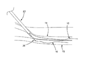
図2は本発明に係る前記装置のばね荷重がかけられた「固定」電極の実施形態の一実施例を図示する。シース23及び静脈ガイドワイヤ13は第一導管或いは静脈14に配置される。針26は前記静脈14から挿通させて隣接する第二脈管または動脈15に進入する。電極ガイドワイヤ16は前記針26のルーメンにより挿入されて前記動脈15に進入する。ここでは、前記針26が引き抜かれる。ちなみに、ここでは処置箇所に対する本発明について説明し、前記第一脈管は静脈であり、前記第二脈管は動脈である。本出願において説明する本発明に係るシステム及び方法は、当然ながら、他の箇所にも応用可能であり、解剖学的方法は隣接する空間または導管の間に吻合を作成するのに適することが本技術分野の技術者ならば理解できる。
FIG. 2 illustrates an embodiment of a spring-loaded "fixed" electrode of the device according to the invention. The
図3を参照する。前記針26が引き抜かれた後(図2参照)、前記カテーテル6の前記本体9が前記静脈ガイドワイヤ13に追随され、本体ルーメン24により延出され、前記静脈14に進入する。前記電極ガイドワイヤ16は電極ルーメン25に挿入される。前記カテーテルが前進すると、前記電極21が前記本体9から分離されると共に前記動脈ルーメン16に進入する。
See FIG. After the
図4を参照する。次の前記電極ガイドワイヤ16が引き抜かれ、ばね荷重がかけられた前記電極21が前記カテーテル本体の方向へ弾性的に偏向するため、動脈壁及び静脈壁に対して圧力がかけられる。前記電極21にエネルギーが供給されると共に前記脈管壁が切断される。
See FIG. The next
前記電極はステンレス鋼、ニチノール、ニクロム、または相似する材料で構築される。前記電極の形状は前記壁を圧迫させるか、緊張ワイヤが前記脈管壁に対して前記電極を引っ張るために用いられる。前記電極21に高周波(Radio Frequency)、超音波、または抵抗熱エネルギーが供給される。
The electrodes are constructed from stainless steel, nitinol, nichrome, or similar materials. The shape of the electrode is used to compress the wall or for a tension wire to pull the electrode against the vessel wall. Radio frequency (Radio Frequency), ultrasonic waves, or resistance thermal energy is supplied to the
図5に示されるように、起動後に、前記電極21が前記カテーテル6の前記本体内に完全に格納される。前記カテーテル6が引き抜かれ、前記静脈14及び前記動脈15を接続する吻合32が残される。
As shown in FIG. 5, after activation, the
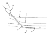
次いで、図6乃至図11を参照する。弾性的に偏向する切断電極21の第二実施例を図示する。本実施例において、ばね荷重がかけられた「固定」電極を備え、針26は患者の皮膚27を挿通させると共に前記静脈14へのアクセスを獲得し、前記隣接動脈15に挿通させるために用いられる。図6に示されるように、A.014”ガイドワイヤ13が前記針ルーメンにより配置され、前記動脈15に進入する。
Then, refer to FIGS. 6 to 11. A second embodiment of the elastically deflecting cutting
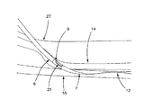
図7に示されるように、前記カテーテル6はガイドワイヤ13に追随して前記静脈14に進入し、前記拡張器先端7が前記動脈15に進入する。前記本体9及び切断電極21は前記静脈に留置される。
As shown in FIG. 7, the
特に図8によると、続いて前記電極21により電極ガイドワイヤ16が前記静脈14に配置される。図9によれば、前記カテーテル6が前進し、ばね荷重がかけられた前記電極21が前記本体9から持ち上げられ、前記動脈(15)壁及び前記静脈(14)壁を圧着させる。
In particular, according to FIG. 8, the
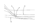
図10に示されるように、続いて前記電極ガイドワイヤ16が引き抜かれ、ばね荷重がかけられた前記電極21により前記動脈15及び前記静脈14が前記カテーテル前記本体9に対して圧迫される。ここでは、高周波、超音波、または抵抗熱技術により前記電極21にエネルギーが供給され、前記脈管の間の吻合が切断される。エネルギーが供給された後、図11に示されるように、前記電極21が前記本体9内に格納され、前記動脈と静脈との間の前記吻合が切断される。前記吻合が完成すると、前記装置30が引き抜かれる。
As shown in FIG. 10, the
図12乃至図17は、本発明の手順について論述するために前記切断電極21の第三実施形態を図示する。この実施形態及び方法では、図12に示されるように、静脈(14)アクセス及び動脈(15)アクセスを獲得するために微細穿刺針12が用いられ、ガイドワイヤ13が前記動脈15に配置される。図13に示されるように、静脈(14)アクセス及び動脈(15)アクセスが得られた後、前記拡張器先端7が前進して前記動脈15に進入し、静脈電極ガイドワイヤ16が前記静脈カテーテル6のルーメンに下方に前進すると共に前記静脈に進入する。
12 to 17 illustrate a third embodiment of the cutting
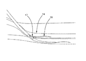
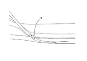
図14を参照する。前記ハンドル1の前記親指タブ3が前進し、これにより前記静脈カテーテルルーメン17が延出されて前記静脈14に進入する。図15に図示されるように、次いで前記静脈ガイドワイヤ13引き抜かれ、切断ワイヤ18は、好ましくはNiTiまたはステンレス鋼のような好適な材料で形成され、前記静脈カテーテルルーメン17に前進する。前記切断ワイヤ18の近位端の成形された取付部品は前記カテーテルのハンドル1の近位端に配置されるようにロックされ、前記切断ワイヤの長さが設定される。
See FIG. The thumb tab 3 of the
図16は前記親指タブ3が引き抜かれることにより前記静脈ルーメン17が引き抜かれることを図示する。この位置では、瘻を作成するために前記切断電極18が使用される。前記切断電極にエネルギー(高周波、超音波、または直接加熱)が供給された後、前記切断電極が隙間を切断し、前記吻合が形成される。前記吻合が完成すると、前記装置30が引き抜かれる。
FIG. 16 illustrates that the
図17は図12乃至図17の具体的な実施例における前記切断ワイヤ18を保持及び解除する一アプローチを図示する。図示されるように、前記切断ワイヤ18はポリイミド絶縁体20または他の好適な材料を含み、前記切断電極21が前記部分20の遠隔端に配置される。高周波動力源等のエネルギー源に接続するためのコネクタ22により前記電極21にエネルギーが供給される。ルアーロックコネクタ19は前記静脈ルーメン17の反対端に配置され、前記ルアーロックコネクタ19から前記切断ワイヤ18が延出され、前記ルアーロックコネクタ19に進入するように前記切断ワイヤ18が引き抜かれる。
FIG. 17 illustrates an approach of holding and releasing the
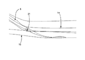
図18乃至図22は本発明の第四実施例に係る前記切断システムを図示する。この実施例では、図18に示されるように、微細穿刺針26が前記皮膚27に挿通された後、前記静脈(14)アクセス及び前記動脈(15)アクセスを得るために使用される。前記針26の前記ルーメンによりガイドワイヤ16が前記動脈15に配置される。そして、図19を参照する。前記カテーテル6が先行して配置された前記ガイドワイヤ16に前記静脈14を通して追随され、前記本体9が前記動脈に展開されるまで前記隣接動脈15に進入する。前記拡張器先端7はスムーズで先細になっており、前記皮膚及び脈管をシースを配置せずに拡張させる。
18 to 22 illustrate the cutting system according to the fourth embodiment of the present invention. In this example, as shown in FIG. 18, the
前記本体9は位置決め機構28を有し、前記本体が前記動脈に進入した際に適切な位置で検出を行い、前記カテーテルを正しい場所に位置するように補助する。前記位置決め機構28は、例えば、圧力センサー、放射線不透過マーカー、またはブリードポートであり、高圧の動脈に位置される際に血液を外部可視ポートから絞り出し、これにより前記動脈への進入を施術者に示す。
The
前記電極21は緊張ワイヤ、滑りカム、または他の好適な方法により前記動脈15中に展開される(図20参照)。
The
展開後、前記カテーテル6が引き抜かれ、図21に示されるように、前記電極21が係合されると共に前記動脈(15)壁及び前記静脈(14)壁が圧迫される。次いで、前記電極21にエネルギーが供給され、前記吻合が切断される。
After deployment, the
前記吻合が完全に形成され、前記電極21が引き抜かれると共に前記本体9に完全に格納され、図22に示されるように、その後前記カテーテル6が前記処置箇所から引き抜かれる。
The anastomosis is fully formed, the
以上のように、本発明に係る実施例及び方法を図示して説明したが、ここで使用される全ての用語は説明に用いるのみであり、制限するためのものではない。本分野で通常知識を有する者ならば、本発明の精神及び目的から逸脱することなく、これらを変更、改修、及び代替可能であることを理解すべきである。 As described above, the examples and methods according to the present invention have been illustrated and described, but all the terms used here are used only for explanation and are not intended to limit them. Those with conventional knowledge in the art should understand that they can be modified, modified and replaced without departing from the spirit and purpose of the invention.
1 ハンドル
2 第一アクチュエータ
3 第二アクチュエータ
4 本体ルーメンルアー
5 電極ルーメンルアー
6 カテーテル
7 拡張器先端
8 カテーテルシャフト
9 本体
10 本体ルーメン末端
12 針
13 静脈ガイドワイヤ
14 第一導管或いは静脈
15 動脈
16 電極ガイドワイヤ
17 静脈カテーテルルーメン
18 切断ワイヤ
20 ポリイミド絶縁体
21 切断電極
23 シース
24 本体ルーメン
26 針
27 皮膚
28 位置決め機構
30 装置
32 吻合
1 Handle 2 1st actuator 3 2nd actuator 4 Main body lumen lure 5
Claims (27)
ルーメン及び先細遠隔端を有する本体を含み、第一ガイドワイヤにより前記第一解剖学的構造に遠位に移動するカテーテルと、
第二ガイドワイヤに追随するルーメンと共に前記本体に格納され、前記第二解剖学的構造に挿入可能である、長尺の、エネルギー供給可能な均一材料のみからなる切断電極と、
前記第一解剖学的構造を定義する組織壁を切断するために前記切断電極にエネルギーを供給するエネルギー供給機構と、を備え、
前記切断電極は弾性的に偏向すると共に前記第二解剖学的構造に前進する際に前記解剖学的構造の壁の間に対して圧力をかけることを特徴とする、
カテーテル及び組織切断システム。 A catheter and tissue cutting system for percutaneously creating an anastomosis between the first and second anatomical structures.
A catheter that includes a body with lumens and a tapered remote end and is moved distally to the first anatomy by a first guide wire.
A cutting electrode consisting only of a long, energy-supplying uniform material that is housed in the body with a lumen that follows the second guide wire and can be inserted into the second anatomy.
And a energy supply mechanism for supplying energy to the cutting electrode tissue wall defining the first anatomy disconnect to order,
Characterized Rukoto pressured against between the wall of the anatomical structure when the cutting electrode is advanced into the second anatomical structure with elastically deflected,
Catheter and tissue cutting system.
遠位に移動すると共に遠位に移動する際に組織を穿刺させる穿刺部材と、
前記穿刺部材により作成された開口部を通して血管に遠位に移動するルーメンを有する本体を含むカテーテルと、
前記本体ルーメンに配置可能であり、且つ前記本体ルーメンにより前記血管に遠位に挿入されるか前記血管に近接される、長尺の、エネルギー供給可能な均一材料のみからなる切断電極と、
前記切断電極の出し入れ操作を行うためのアクチュエータと、
前記血管を定義する組織壁を切断するために前記切断電極にエネルギーを供給するエネルギー供給機構と、を備え、
前記切断電極は弾性的に偏向すると共に前記第二解剖学的構造に前進する際に前記解剖学的構造の壁の間に対して圧力をかけることを特徴とする、
血管内アクセスとガイドワイヤの配置を作成するためのカテーテル及び組織切断システム。
A catheter and tissue cutting system for creating intravascular access and indwelling guide wires.
A puncture member that moves distally and punctures tissue when moving distally,
A catheter containing a body having a lumen that moves distally to the blood vessel through the opening created by the puncture member.
A cutting electrode consisting only of a long, energy-supplying, uniform material that can be placed in the body lumen and is inserted distally into or close to the blood vessel by the body lumen.
An actuator for inserting and removing the cutting electrode and
And a energy supply mechanism for supplying energy to the cutting electrode tissue walls defining said vessel disconnect to order,
Characterized Rukoto pressured against between the wall of the anatomical structure when the cutting electrode is advanced into the second anatomical structure with elastically deflected,
Catheter and tissue cutting system for creating intravascular access and guidewire placement.
Applications Claiming Priority (3)
| Application Number | Priority Date | Filing Date | Title |
|---|---|---|---|
| US201762507362P | 2017-05-17 | 2017-05-17 | |
| US62/507,362 | 2017-05-17 | ||
| PCT/US2018/033259 WO2018213626A1 (en) | 2017-05-17 | 2018-05-17 | Single catheter electrode tissue cutting system for creating anastomoses |
Publications (3)
| Publication Number | Publication Date |
|---|---|
| JP2020518355A JP2020518355A (en) | 2020-06-25 |
| JP2020518355A5 JP2020518355A5 (en) | 2021-04-08 |
| JP6869375B2 true JP6869375B2 (en) | 2021-05-12 |
Family
ID=64270279
Family Applications (1)
| Application Number | Title | Priority Date | Filing Date |
|---|---|---|---|
| JP2019559313A Active JP6869375B2 (en) | 2017-05-17 | 2018-05-17 | Single catheter electrode tissue cutting system for creating anastomosis |
Country Status (6)
| Country | Link |
|---|---|
| US (2) | US11660140B2 (en) |
| EP (1) | EP3624719A4 (en) |
| JP (1) | JP6869375B2 (en) |
| AU (1) | AU2018269737B2 (en) |
| CA (1) | CA3060869A1 (en) |
| WO (1) | WO2018213626A1 (en) |
Families Citing this family (5)
| Publication number | Priority date | Publication date | Assignee | Title |
|---|---|---|---|---|
| CA3060869A1 (en) * | 2017-05-17 | 2018-11-22 | Avenu Medical, Inc. | Single catheter electrode tissue cutting system for creating anastomoses |
| RU195607U1 (en) * | 2019-08-09 | 2020-02-03 | федеральное государственное бюджетное образовательное учреждение высшего образования "Саратовский государственный медицинский университет имени В.И. Разумовского" Министерства здравоохранения Российской Федерации (ФГБОУ ВО Саратовский ГМУ им. В.И. Разумовского Минздрава России) | Device for radiofrequency destruction of the lower alveolar nerve |
| US11793623B1 (en) * | 2019-10-14 | 2023-10-24 | Avenu Medical, Inc | Systems and methods for percutaneously placing biologic grafts at a procedural site |
| US20220023621A1 (en) * | 2020-07-27 | 2022-01-27 | Medtronic, Inc. | Implantable medical lead |
| EP4074352A1 (en) | 2021-04-12 | 2022-10-19 | Mallios Consulting | Devices for forming percutaneous vascular anastomosis, in particular percutaneous arteriovenous fistula for hemodialysis |
Family Cites Families (20)
| Publication number | Priority date | Publication date | Assignee | Title |
|---|---|---|---|---|
| WO1997032532A1 (en) | 1996-03-05 | 1997-09-12 | Vnus Medical Technologies, Inc. | Vascular catheter-based system for heating tissue |
| JP4000631B2 (en) | 1997-07-03 | 2007-10-31 | 日本ゼオン株式会社 | Electrosurgical instrument |
| JP2000237202A (en) | 1999-02-25 | 2000-09-05 | Olympus Optical Co Ltd | Treating utensil for endoscope |
| US8926545B2 (en) * | 2004-08-27 | 2015-01-06 | Rox Medical, Inc. | Device and method for establishing an artificial arterio-venous fistula |
| US20060111704A1 (en) | 2004-11-22 | 2006-05-25 | Rox Medical, Inc. | Devices, systems, and methods for energy assisted arterio-venous fistula creation |
| WO2010042686A1 (en) | 2008-10-09 | 2010-04-15 | Sharma Virender K | Method and apparatus for stimulating the vascular system |
| WO2011159825A1 (en) | 2010-06-15 | 2011-12-22 | Caymus Medical, Inc. | Intravascular arterial to venous anastomosis and tissue welding catheter |
| WO2011159802A1 (en) | 2010-06-15 | 2011-12-22 | Caymus Medical, Inc. | Systems and methods for creating arteriovenous (av) fistulas |
| US9138230B1 (en) | 2011-04-29 | 2015-09-22 | Avenu Medical, Inc. | Systems and methods for creating arteriovenous (AV) fistulas |
| CA2854593C (en) | 2011-11-04 | 2019-07-16 | Caymus Medical, Inc. | Systems and methods for percutaneous intravascular access and guidewire placement |
| EP2812063B1 (en) | 2012-02-08 | 2020-03-25 | Avenu Medical, Inc. | Intravascular arterial to venous anastomosis and tissue welding catheter |
| CA2880253C (en) | 2012-08-01 | 2020-07-28 | Avenu Medical, Inc. | Systems and methods for percutaneous intravascular access for arteriovenous fistula |
| JP2015532152A (en) * | 2012-10-11 | 2015-11-09 | ティーブイエー メディカル, インコーポレイテッド | Apparatus and method for fistula formation |
| AU2013344595B2 (en) | 2012-11-14 | 2017-09-28 | Avenu Medical, Inc. | Intravascular arterial to venous anastomosis and tissue welding catheter |
| ES2813871T3 (en) | 2013-02-21 | 2021-03-25 | Boston Scient Scimed Inc | Devices to form an anastomosis |
| US9962527B2 (en) * | 2013-10-16 | 2018-05-08 | Ra Medical Systems, Inc. | Methods and devices for treatment of stenosis of arteriovenous fistula shunts |
| CN106535800A (en) | 2014-07-10 | 2017-03-22 | 奥林巴斯株式会社 | Endoscopic submucosal dissection device and endoscope system |
| US20190069949A1 (en) * | 2014-12-03 | 2019-03-07 | Metavention, Inc. | Systems and methods for modulatng nerves or other tissue |
| JP6830911B2 (en) * | 2015-03-10 | 2021-02-17 | ステント・テック・リミテッドStent Tek Limited | Surgical systems and devices for percutaneous creation of autologous vascularized subcutaneous arteriovenous fistula (AVF) |
| CA3060869A1 (en) * | 2017-05-17 | 2018-11-22 | Avenu Medical, Inc. | Single catheter electrode tissue cutting system for creating anastomoses |
-
2018
- 2018-05-17 CA CA3060869A patent/CA3060869A1/en active Pending
- 2018-05-17 WO PCT/US2018/033259 patent/WO2018213626A1/en unknown
- 2018-05-17 AU AU2018269737A patent/AU2018269737B2/en active Active
- 2018-05-17 US US15/982,946 patent/US11660140B2/en active Active
- 2018-05-17 EP EP18803291.6A patent/EP3624719A4/en active Pending
- 2018-05-17 JP JP2019559313A patent/JP6869375B2/en active Active
-
2020
- 2020-08-31 US US17/008,412 patent/US11786299B2/en active Active
Also Published As
| Publication number | Publication date |
|---|---|
| WO2018213626A1 (en) | 2018-11-22 |
| US20180333203A1 (en) | 2018-11-22 |
| US11786299B2 (en) | 2023-10-17 |
| US20200397438A1 (en) | 2020-12-24 |
| EP3624719A1 (en) | 2020-03-25 |
| AU2018269737A1 (en) | 2019-11-07 |
| AU2018269737B2 (en) | 2023-07-27 |
| EP3624719A4 (en) | 2021-01-27 |
| JP2020518355A (en) | 2020-06-25 |
| US11660140B2 (en) | 2023-05-30 |
| CA3060869A1 (en) | 2018-11-22 |
Similar Documents
| Publication | Publication Date | Title |
|---|---|---|
| US11950828B2 (en) | Intravascular arterial to venous anastomosis and tissue welding catheter | |
| JP6869375B2 (en) | Single catheter electrode tissue cutting system for creating anastomosis | |
| US20230302214A1 (en) | Systems and methods for creating arteriovenous (av) fistulas | |
| US9955972B1 (en) | Systems and methods for creating arteriovenous (AV) fistulas | |
| JP5964445B2 (en) | System and method for percutaneous endovascular access and guidewire placement | |
| US20110306959A1 (en) | Intravascular arterial to venous anastomosis and tissue welding catheter | |
| US10736635B1 (en) | Externally supported anastomosis | |
| AU2015200498B2 (en) | Systems and methods for creating arteriovenous (AV) fistulas |
Legal Events
| Date | Code | Title | Description |
|---|---|---|---|
| A521 | Request for written amendment filed |
Free format text: JAPANESE INTERMEDIATE CODE: A523 Effective date: 20191105 |
|
| A621 | Written request for application examination |
Free format text: JAPANESE INTERMEDIATE CODE: A621 Effective date: 20191031 |
|
| A521 | Request for written amendment filed |
Free format text: JAPANESE INTERMEDIATE CODE: A523 Effective date: 20200417 |
|
| A977 | Report on retrieval |
Free format text: JAPANESE INTERMEDIATE CODE: A971007 Effective date: 20201013 |
|
| A131 | Notification of reasons for refusal |
Free format text: JAPANESE INTERMEDIATE CODE: A131 Effective date: 20201020 |
|
| A601 | Written request for extension of time |
Free format text: JAPANESE INTERMEDIATE CODE: A601 Effective date: 20210108 |
|
| A524 | Written submission of copy of amendment under article 19 pct |
Free format text: JAPANESE INTERMEDIATE CODE: A524 Effective date: 20210225 |
|
| TRDD | Decision of grant or rejection written | ||
| A01 | Written decision to grant a patent or to grant a registration (utility model) |
Free format text: JAPANESE INTERMEDIATE CODE: A01 Effective date: 20210406 |
|
| A61 | First payment of annual fees (during grant procedure) |
Free format text: JAPANESE INTERMEDIATE CODE: A61 Effective date: 20210413 |
|
| R150 | Certificate of patent or registration of utility model |
Ref document number: 6869375 Country of ref document: JP Free format text: JAPANESE INTERMEDIATE CODE: R150 |
|
| R250 | Receipt of annual fees |
Free format text: JAPANESE INTERMEDIATE CODE: R250 |


