JP6868088B2 - Adjustable back cover for timekeeper - Google Patents
Adjustable back cover for timekeeper Download PDFInfo
- Publication number
- JP6868088B2 JP6868088B2 JP2019233841A JP2019233841A JP6868088B2 JP 6868088 B2 JP6868088 B2 JP 6868088B2 JP 2019233841 A JP2019233841 A JP 2019233841A JP 2019233841 A JP2019233841 A JP 2019233841A JP 6868088 B2 JP6868088 B2 JP 6868088B2
- Authority
- JP
- Japan
- Prior art keywords
- back cover
- annular
- portable watch
- braking means
- watch case
- Prior art date
- Legal status (The legal status is an assumption and is not a legal conclusion. Google has not performed a legal analysis and makes no representation as to the accuracy of the status listed.)
- Active
Links
- 230000000295 complement effect Effects 0.000 claims description 5
- 239000000463 material Substances 0.000 claims description 5
- 210000000707 wrist Anatomy 0.000 description 2
- 239000000919 ceramic Substances 0.000 description 1
- 239000002131 composite material Substances 0.000 description 1
- 230000006835 compression Effects 0.000 description 1
- 238000007906 compression Methods 0.000 description 1
- 210000002858 crystal cell Anatomy 0.000 description 1
- 239000004973 liquid crystal related substance Substances 0.000 description 1
- 238000003754 machining Methods 0.000 description 1
- 238000004519 manufacturing process Methods 0.000 description 1
- 239000002184 metal Substances 0.000 description 1
- 229910001092 metal group alloy Inorganic materials 0.000 description 1
- 230000004048 modification Effects 0.000 description 1
- 238000012986 modification Methods 0.000 description 1
- 239000004033 plastic Substances 0.000 description 1
- 238000007789 sealing Methods 0.000 description 1
- 238000000926 separation method Methods 0.000 description 1
- 239000000758 substrate Substances 0.000 description 1
- 238000004804 winding Methods 0.000 description 1
Images


Classifications
-
- G—PHYSICS
- G04—HOROLOGY
- G04B—MECHANICALLY-DRIVEN CLOCKS OR WATCHES; MECHANICAL PARTS OF CLOCKS OR WATCHES IN GENERAL; TIME PIECES USING THE POSITION OF THE SUN, MOON OR STARS
- G04B37/00—Cases
- G04B37/12—Cases for special purposes, e.g. watch combined with ring, watch combined with button
-
- G—PHYSICS
- G04—HOROLOGY
- G04B—MECHANICALLY-DRIVEN CLOCKS OR WATCHES; MECHANICAL PARTS OF CLOCKS OR WATCHES IN GENERAL; TIME PIECES USING THE POSITION OF THE SUN, MOON OR STARS
- G04B37/00—Cases
- G04B37/0008—Cases for pocket watches and wrist watches
-
- G—PHYSICS
- G04—HOROLOGY
- G04B—MECHANICALLY-DRIVEN CLOCKS OR WATCHES; MECHANICAL PARTS OF CLOCKS OR WATCHES IN GENERAL; TIME PIECES USING THE POSITION OF THE SUN, MOON OR STARS
- G04B45/00—Time pieces of which the indicating means or cases provoke special effects, e.g. aesthetic effects
- G04B45/0084—Pictures or inscriptions on the case or parts thereof, attaching complete pictures
-
- G—PHYSICS
- G04—HOROLOGY
- G04B—MECHANICALLY-DRIVEN CLOCKS OR WATCHES; MECHANICAL PARTS OF CLOCKS OR WATCHES IN GENERAL; TIME PIECES USING THE POSITION OF THE SUN, MOON OR STARS
- G04B19/00—Indicating the time by visual means
- G04B19/28—Adjustable guide marks or pointers for indicating determined points of time
- G04B19/283—Adjustable guide marks or pointers for indicating determined points of time on rotatable rings, i.e. bezel
- G04B19/286—Adjustable guide marks or pointers for indicating determined points of time on rotatable rings, i.e. bezel with locking means to prevent undesired rotations in both directions
-
- G—PHYSICS
- G04—HOROLOGY
- G04B—MECHANICALLY-DRIVEN CLOCKS OR WATCHES; MECHANICAL PARTS OF CLOCKS OR WATCHES IN GENERAL; TIME PIECES USING THE POSITION OF THE SUN, MOON OR STARS
- G04B37/00—Cases
- G04B37/08—Hermetic sealing of openings, joints, passages or slits
- G04B37/11—Hermetic sealing of openings, joints, passages or slits of the back cover of pocket or wrist watches
-
- G—PHYSICS
- G04—HOROLOGY
- G04B—MECHANICALLY-DRIVEN CLOCKS OR WATCHES; MECHANICAL PARTS OF CLOCKS OR WATCHES IN GENERAL; TIME PIECES USING THE POSITION OF THE SUN, MOON OR STARS
- G04B45/00—Time pieces of which the indicating means or cases provoke special effects, e.g. aesthetic effects
- G04B45/0084—Pictures or inscriptions on the case or parts thereof, attaching complete pictures
- G04B45/0092—Changeable parts
-
- G—PHYSICS
- G04—HOROLOGY
- G04B—MECHANICALLY-DRIVEN CLOCKS OR WATCHES; MECHANICAL PARTS OF CLOCKS OR WATCHES IN GENERAL; TIME PIECES USING THE POSITION OF THE SUN, MOON OR STARS
- G04B37/00—Cases
- G04B37/0075—Cases with means to enhance sound transmission
Landscapes
- Physics & Mathematics (AREA)
- General Physics & Mathematics (AREA)
- Electric Clocks (AREA)
Description
本発明は、計時器用の裏蓋に関し、より詳細には、外面にパターン又はロゴがあり所望に応じてこのパターン又はロゴの向きを調整することができるような計時器用の裏蓋に関する。 The present invention relates to a timekeeping back cover, and more particularly to a timekeeping back cover having a pattern or logo on the outer surface and capable of adjusting the orientation of the pattern or logo as desired.
携行型時計(例、腕時計、懐中時計)のケースの裏蓋をそのミドル部にねじ込んで裏蓋が完全にねじ込まれているときに、装飾性の模様又は刻印が、この携行型時計の12時−6時の垂直軸に対して適切にアライメント状態になっていないことがしばしば観察され、このことは当然、この携行型時計の美観を損ねてしまう。このような装飾性の模様又は刻印は、例えば、この携行型時計を装着している個人の手首の側にある裏蓋の面にスタンピングされていたり刻まれたりしている。 When the back cover of the case of a portable watch (eg, wristwatch, pocket watch) is screwed into its middle part and the back cover is completely screwed in, the decorative pattern or engraving is at 12 o'clock on this portable watch. It is often observed that the watch is not properly aligned with the -6 o'clock vertical axis, which, of course, spoils the aesthetics of this portable watch. Such decorative patterns or inscriptions are stamped or engraved, for example, on the surface of the case back on the side of the wrist of the individual wearing the portable watch.
このような美観上の問題は、低コストの携行型時計では許容される可能性があるが、より高価な携行型時計の場合は非常に大きな課題となってしまう。 Such aesthetic problems may be acceptable for low-cost portable watches, but become a huge challenge for more expensive portable watches.
この課題を解決するために今までに知られている唯一の策は、機械加工時に裏蓋と所定の携行型時計ケースを対にして、完全にねじ込まれたときに裏蓋が携行型時計の12時−6時の軸と完全にアライメント状態になることを確実にするものである。しかし、この策はあまり満足できるものではない。なぜなら、上記のことによって、携行型時計の元々の裏蓋がなくなったり破損したりした場合には問題が発生し、別の裏蓋に取り替えなければならなくなり、このために、裏蓋をミドル部にねじ込んでも、裏蓋が12時−6時の鉛直方向の軸に対して適切にアライメント状態になることが確実ではなくなるためである。 The only known solution to this problem is to pair the back cover with a given portable watch case during machining, and when fully screwed, the back cover of the portable watch. It ensures that the axis is perfectly aligned with the 12 o'clock-6 o'clock axis. However, this measure is not very satisfactory. Because of the above, if the original back cover of the portable watch is lost or damaged, a problem will occur and you will have to replace it with another back cover, which is why the back cover is in the middle part. This is because it is not certain that the back cover will be properly aligned with the vertical axis at 12 o'clock to 6 o'clock even if it is screwed into.
本発明は、携行型時計ケースのミドル部に裏蓋をねじ込んだ後に裏蓋の向きを携行型時計に対して単純かつ効果的に調整して、この携行型時計を装着した個人の手首の方を向いている携行型時計の裏蓋の面に刻まれた刻印や他の装飾パターンが適切に配置されることを確実にすることを可能にするシステムを提案することによって、上記の課題や他の課題を解決することを目的とする。 In the present invention, after screwing the back cover into the middle part of the portable watch case, the orientation of the back cover is simply and effectively adjusted with respect to the portable watch, and the wrist of an individual wearing this portable watch. By proposing a system that makes it possible to ensure that the inscriptions and other decorative patterns engraved on the back cover of a portable watch facing the face are properly placed, the above challenges and others. The purpose is to solve the problems of.
このために、本発明は、携行型時計ケース用の裏蓋に関し、この裏蓋は、前記携行型時計ケースにねじ込まれるように構成している第1の要素と、及び端面にパターンがある第2の要素とを備え、前記第2の要素は、前記第2の要素の中央領域を通る回転軸を中心として回転することができるように取り付けられており、前記第2の要素は、前記第2の要素に対して前記回転軸を中心とする異なる角位置に保持するように構成している制動手段を備え、前記制動手段は、前記第1の要素との間に配置されている。 To this end, the present invention relates to a back cover for a portable watch case, the back cover having a first element configured to be screwed into the portable watch case and a pattern on the end face. The second element is provided with two elements, the second element is attached so as to be rotatable about a rotation axis passing through a central region of the second element, and the second element is the second element. A braking means configured to hold the two elements at different angular positions about the rotation axis is provided, and the braking means is arranged between the two elements and the first element.
これらの特徴のおかげで、本発明は、裏蓋を携行型時計のケースミドル部に完全にねじ込むことを可能にして、そのシールを確実にし、そして、可能なかぎりこの裏蓋を失うリスクをなくすような携行型時計ケースの裏部を固定するデバイスを提供する。また、この裏蓋は、所定の位置に完全にねじ込まれていても、この裏蓋の可動要素をケースミドル部に対して回転させて、前記裏蓋の可視面に施された刻印又はパターンの潜在的なアラインメントずれを補正することを可能にする。 Thanks to these features, the present invention allows the case back to be fully screwed into the case middle of the portable watch, ensuring its seal and eliminating the risk of losing this back cover as much as possible. To provide a device for fixing the back of such a portable watch case. Further, even if the back cover is completely screwed into a predetermined position, the movable element of the back cover is rotated with respect to the case middle portion to form a marking or pattern on the visible surface of the back cover. It makes it possible to correct potential misalignment.
本発明の他の有利な代替実施形態は、以下の特徴を有する。
− 前記制動手段は、摩擦によって作用する。
− 前記制動手段は、少なくとも1つの弾性環状要素を有する。
− 前記少なくとも1つの環状要素は、前記第2の要素の回転軸に平行な方向にて弾性を有する。
− 前記制動手段は、圧縮可能な材料によって作られたリング状のガスケットによって形成される。
− 前記第1の要素と前記第2の要素はそれぞれ、互いに相補的なクリップ手段を有する。
− 前記第2の要素は、前記第1の要素に形成される環状溝と係合するように構成しているピンを有する。
− 前記第2の要素は、互いに対向しており前記第1の要素に形成される第1及び第2の環状スロット内に収容される2つの弾性環状要素を有する。
− 前記環状スロットは、円形溝の両側に配置される。
− 前記第2の環状スロットには、底部を形成し弾性環状要素を受けるように構成している第1のレベルと、及び第2の要素の縁部を受けるように構成している第2のレベルとの2つのレベルがある。
− 裏蓋とケースとの間のシールを確実にするために、携行型時計ケースの底部に形成された環状溝にOリングが挿入される。
Other advantageous alternative embodiments of the present invention have the following features:
-The braking means acts by friction.
-The braking means has at least one elastic annular element.
-The at least one annular element has elasticity in a direction parallel to the axis of rotation of the second element.
-The braking means is formed by a ring-shaped gasket made of a compressible material.
-The first element and the second element each have complementary clipping means.
-The second element has a pin configured to engage an annular groove formed in the first element.
-The second element has two elastic annular elements that face each other and are housed in first and second annular slots formed in the first element.
-The annular slots are arranged on both sides of the circular groove.
-The second annular slot has a first level configured to form a bottom and receive an elastic annular element and a second level configured to receive the edge of the second element. There are two levels, the level.
-O-rings are inserted into the annular groove formed in the bottom of the portable watch case to ensure a seal between the case back and the case.
本発明は、さらに、本発明に係る月の相の機構を有する計時器に関する。 The present invention further relates to a timekeeper having a lunar phase mechanism according to the present invention.
図示している少なくとも1つの実施形態(これに限定されない)に基づく以下の説明を読むことによって、本携行型時計の目的、利点及び特徴を明確に理解することができるであろう。 By reading the following description based on at least one embodiment (but not limited to) illustrated, one will be able to clearly understand the purpose, advantages and features of the portable watch.
図1は、ケースミドル部51に特定のねじピッチでねじ込まれるように意図されている携行型時計ケース50のための裏蓋1であり、このケースミドル部51には、その底部の内周に、機械加工された相補的なねじ山がある。
FIG. 1 is a back cover 1 for a
具体的には、裏蓋1は、携行型時計ケース50にねじ込まれるように構成している第1の要素10と、ロゴや商標などのパターンがある端面21を有する第2の要素20とを備え、この第2の要素20は、携行型時計ケースの中心を通る軸を中心に回転することができるように取り付けられている。
Specifically, the back cover 1 includes a
第1の要素10は、携行型時計ケース50にねじ込まれるように意図されており、このために、その背面、すなわち、ケースの内側を向いている面、には環状の肩部11があり、この肩部11にはその外周にねじ山110がある。このように、肩部11は携行型時計ケース50の底部にねじ込まれる。この携行型時計ケース50には、このために設けられた相補的なねじ山がある。
The
第1の要素10は、さらに、その前面、すなわち、ケースの外側方向を向いている面に、壁13がある基礎12を備える。この壁13は、この基礎12が実質的に台形の断面を有するように、ケースから離れるにしたがって外側方向に広がるように傾斜している。
The
第2の要素20には、基礎12の位置に、基礎12に対して相補的な形であり傾斜壁23に面している空洞22があり、これによって、2つの要素10、20を力ずくで相互ロックないしクリップし、したがって、組み付けることができる。第1の要素10に第2の要素20を力ずくで入れ込むことを容易にするために、基礎12と空洞22のリムを傾斜させる。
The
好ましいことに、第1の要素10の基礎12には、凹部13’と環状スロット13”があり、この環状スロット13”は、壁13の裏に形成されており、これによって、第2の要素20を第1の要素10に力ずくで相互ロックする際に壁が変形することを容易にする。
Preferably, the
観察することができるように、基礎12及び空洞22の直径はそれぞれ、第1及び第2の要素10、20全体の直径よりも小さい。
As can be observed, the diameters of the
第2の要素20は、ケース100の中心を通り抜ける回転軸Cを中心として第1の要素10に接触して回転することができるように取り付けられ、前記相互ロック又はクリップは、第2の要素20を回転させるのに十分なクリアランスを与える。
The
図2a及び図2bに示しているように、第1の要素10は、順次的に、基礎12に形成される第1の環状スロット14と、第1の要素の周部の近くに形成される環状溝15と、及び第1の要素10の周部のすぐ近くに形成される第2の環状スロット16とを備える。
As shown in FIGS. 2a and 2b, the
図1において、第2の要素20には、ピン25を受けるように構成しているオリフィス24が形成されており、ピン25が、第1の要素10に形成された環状溝15と係合して、第2の要素20をその回転の間ガイドすることがわかる。また、図2aにおいて、環状溝15が連続しておらず、環状溝15の2つの端150及び151どうしが近くにあり、この端150及び151それぞれがバンキングを定めていることがわかる。
In FIG. 1, the
本発明によれば、摩擦によって作用する制動手段が設けられる。この制動手段は、第1の要素10に対する、したがって、ケースミドル部に対する、第2の要素20の異なる角度的な向きを保持するように構成している。したがって、第1の要素10がケースミドル部に当接するようにねじ込まれると、パターンMがある第2の要素は、制動手段によって発生する摩擦力に抗しつつ所望の位置に容易に角度的に変位することができ、所望の位置に保持される。このようにして、第2の要素20は、その背面と第1の要素10の前面との間で軸方向にクランプされる。好ましくは、第2の要素20、そして、第1の要素10、の対応する寸法、特に、厚み、は、第2の要素20の縁部が第1の要素10の前面と同一平面内にあるように選択され、したがって、連続面を形成する。
According to the present invention, a braking means that acts by friction is provided. The braking means is configured to hold different angular orientations of the
1つの好ましい実施形態によれば、制動手段は、特に、回転軸Cに平行な方向にて弾性がある、少なくとも1つの弾性環状要素30を備える。通常、この環状要素は、天然又は合成の圧縮可能な材料によって作られたガスケットによって形成することができる。環状要素30は、第1の要素と第2の要素との間に配置される。本発明によれば、一又は複数の弾性環状要素30は、第1の要素の前面に形成される第1及び第2の環状スロット14及び16内に配置される。当業者であれば、特に困難なく、この組み付けを逆にして、スロット14及び16を予め形成した第2の要素20の背面に弾性環状要素30を配置することができる。環状スロット14及び16は、環状溝15の両側に配置され、弾性環状要素30によって発生される摩擦力のより良好な分布が可能になる。
According to one preferred embodiment, the braking means comprises at least one elastic
好ましいことに、第2の環状スロット16には、弾性環状要素30を受けるように構成しているスロットの底部を形成する第1のレベルと、第2の要素20の縁部を受けるように構成しているスロットの開口を形成する第2のレベルとの2つのレベルがある。この第2のレベルは、第2の要素20の縁部が軸Cの方向に並進変位をすることができるように、第1のレベルの寸法よりも大きい寸法を有する。
Preferably, the second
なお、所望の制動力は、製造時に環状要素の圧縮比を適合させることによって制御することができることに留意すべきである。 It should be noted that the desired braking force can be controlled by adjusting the compression ratio of the annular element during manufacturing.
また、第1の要素に取り付けられる第2の要素を用いることによって、製造業者が、代替の裏蓋の在庫を獲得し、また、異なるパターンを有する裏蓋を用いることができるようになることに留意すべきである。この種の裏蓋によって、さらに、種々の材料を容易に組み合わせてその種々の要素を作ることが可能になる。 Also, by using the second element attached to the first element, the manufacturer will be able to obtain an inventory of alternative back covers and also use back covers with different patterns. It should be noted. This type of back cover also allows the various materials to be easily combined to make their various elements.
したがって、裏蓋の向きを調整するために、製造者(又は着用者)は、携行型時計ケースの方に第2の要素20に圧力を加えて、弾性環状要素30を圧縮する。そして、第2の要素に圧力を加え続けながら、製造者は、第1の要素10に対して第2の要素を回転させて、裏蓋を所望の角位置に向きを調整して、これによって、パターンMが、例えば、携行型時計の6時−12時の軸とアライメント状態になる。
Therefore, in order to adjust the orientation of the back cover, the manufacturer (or the wearer) applies pressure to the
したがって、第1の要素10から第2の要素20を分離することを容易にするために、第2の要素20にはノッチ26を形成し、このノッチ26は、てこの原理を発揮させて第2の要素を取り外す道具を受けることができる。
Therefore, in order to facilitate the separation of the
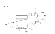
図1には、本発明に係る裏蓋1を備えた計時器100、例えば、腕時計タイプの計時器、を部分的に示している。この計時器は、特に、ベゼル52の下に位置するケースミドル部51を有し、このベゼル52は、ケースミドル部51にねじ込むことができ、風防53を保持するように用いられる。ベゼル52と風防53によって形成されるアセンブリーは、ガスケット54を挿入することによってシールされる。ケースミドル部51には、さらに、ワインディング用ボタン56が固定されるロッド55を通すためのボア穴がある。図に示した例では、腕時計は、アナログ時刻表示タイプのものであり、このために、表盤57の上で動く時針と分針のセット58(図において1つの針のみを示している)を備える。当然、例えば、液晶セルを有する、デジタル時刻表示携行型時計にも本発明を適用することができる。
FIG. 1 partially shows a
添付の特許請求の範囲によって定められる本発明の範囲を逸脱せずに、本明細書に記載された実施形態に対して、当業者にとって自明である種々の改変及び/又は改良を行うことができることを理解することができるであろう。具体的には、リング状のガスケット30の代わりに、軸Cに沿って圧縮可能な弾性を有していれば、波形ばねリングを用いることを考えることができる。別の代替的な実施形態において、制動手段をインデキシング用のノッチに関連づけて、基材を所定の複数の角位置に配置することができる。
Various modifications and / or improvements that are obvious to those skilled in the art can be made to the embodiments described herein without departing from the scope of the invention as defined by the appended claims. Will be able to understand. Specifically, instead of the ring-shaped
なお、ケースミドル部51の底部に設けられた環状溝59にOリング31を伝統的な形態で挿入して、裏蓋1の第1の要素10とケースミドル部51との間のシール性を確実にしている。
The O-
第1の要素と第2の要素は、金属、金属合金、セラミックス、複合材料又はプラスチック材料で作ることができる。 The first and second elements can be made of metal, metal alloys, ceramics, composites or plastic materials.
当然、本発明は、上述した実施形態に限定されず、本発明の範囲を逸脱せずに、種々の単純な代替形態や改変された形態を考えることができる。 Naturally, the present invention is not limited to the above-described embodiment, and various simple alternative forms and modified forms can be considered without departing from the scope of the present invention.
1 裏蓋
10 第1の要素
14、16 環状スロット
15 環状溝
20 第2の要素
24 オリフィス
25 ピン
30 弾性環状要素
31 Oリング
50 携行型時計ケース
51 ケースミドル部
59 環状溝
C 回転軸
M パターン
1 Back cover 10
Claims (11)
前記携行型時計ケース(50)にねじ込まれるように構成している第1の要素(10)と、及び端面にパターン(M)がある第2の要素(20)とを備え、
前記第2の要素(20)は、前記携行型時計ケース(50)の中央領域を通る回転軸(C)を中心として回転することができるように取り付けられており、
前記第2の要素(20)は、前記第2の要素(20)を前記第1の要素(10)に対して前記回転軸(C)を中心とする異なる角位置に保持するように構成している制動手段を備え、
前記制動手段は、前記第1の要素(10)と前記第2の要素(20)との間に配置されており、
前記第2の要素(20)は、前記第2の要素(20)が前記第1の要素(10)に形成された環状溝(15)と係合するように構成しているピン(25)を備える
ことを特徴とする裏蓋(1)。 A back cover (1) for a portable watch case (50),
It comprises a first element (10) configured to be screwed into the portable watch case (50) and a second element (20) having a pattern (M) on the end face.
The second element (20) is attached so as to be able to rotate about a rotation axis (C) passing through a central region of the portable watch case (50).
The second element (20) is configured to hold the second element (20) at a different angular position about the rotation axis (C) with respect to the first element (10). Equipped with braking means
The braking means is arranged between the first element (10) and the second element (20) .
The second element (20) is a pin (25) configured such that the second element (20) engages with an annular groove (15) formed in the first element (10). The back cover (1), which comprises.
ことを特徴とする請求項1に記載の裏蓋(1)。 The back cover (1) according to claim 1, wherein the braking means acts by friction.
ことを特徴とする請求項1又は2に記載の裏蓋(1)。 The back cover (1) according to claim 1 or 2, wherein the braking means has at least one elastic annular element (30).
ことを特徴とする請求項1〜3のいずれか一項に記載の裏蓋(1)。 Any one of claims 1 to 3, wherein the at least one elastic annular element (30) is elastic in a direction parallel to the rotation axis (C) of the second element (20). The back cover (1) according to the item.
ことを特徴とする請求項1〜4のいずれか一項に記載の裏蓋(1)。 The back cover (1) according to any one of claims 1 to 4, wherein the braking means is formed by a ring-shaped gasket (30) made of a compressible material.
ことを特徴とする請求項1〜5のいずれか一項に記載の裏蓋(1)。 The back cover (1) according to any one of claims 1 to 5, wherein each of the first element (10) and the second element (20) has a clipping means complementary to each other. ).
ことを特徴とする請求項3に記載の裏蓋(1)。 Said second element (20) comprises two resilient annular element housed within the first and second annular slots facing each other formed on the first element (10) in (14, 16) The back cover (1) according to claim 3, further comprising (30).
ことを特徴とする請求項7に記載の裏蓋(1)。 The back cover (1) according to claim 7 , wherein the first and second annular slots (14, 16) are formed on both sides of the annular groove (15).
ことを特徴とする請求項7または8に記載の裏蓋(1)。 The second annular slot (16) has a first level that forms the bottom and is configured to receive an elastic annular element (30), and an edge of the second element (20). The back cover (1) according to claim 7 or 8 , wherein there are two levels, a second level configured to receive the portion.
ことを特徴とする請求項1〜9のいずれか一項に記載の裏蓋(1)。 An O-ring in an annular groove (59) formed in the bottom of the portable watch case (50) to ensure a seal between the back cover (1) and the portable watch case (50). The back cover (1) according to any one of claims 1 to 9 , wherein (31) is inserted.
ことを特徴とする計時器。 A timekeeping device having the back cover according to any one of claims 1 to 10.
Applications Claiming Priority (2)
| Application Number | Priority Date | Filing Date | Title |
|---|---|---|---|
| EP19151038.7A EP3680729B1 (en) | 2019-01-09 | 2019-01-09 | Rotatably adjustable back for a clock piece |
| EP19151038.7 | 2019-01-09 |
Publications (2)
| Publication Number | Publication Date |
|---|---|
| JP2020112550A JP2020112550A (en) | 2020-07-27 |
| JP6868088B2 true JP6868088B2 (en) | 2021-05-12 |
Family
ID=65011927
Family Applications (1)
| Application Number | Title | Priority Date | Filing Date |
|---|---|---|---|
| JP2019233841A Active JP6868088B2 (en) | 2019-01-09 | 2019-12-25 | Adjustable back cover for timekeeper |
Country Status (4)
| Country | Link |
|---|---|
| US (1) | US11698607B2 (en) |
| EP (1) | EP3680729B1 (en) |
| JP (1) | JP6868088B2 (en) |
| CN (1) | CN111427251B (en) |
Families Citing this family (2)
| Publication number | Priority date | Publication date | Assignee | Title |
|---|---|---|---|---|
| EP3958067A1 (en) * | 2020-08-17 | 2022-02-23 | The Swatch Group Research and Development Ltd | Device for attaching a bottom on a middle for a clockpiece |
| EP4194967A1 (en) * | 2021-12-07 | 2023-06-14 | The Swatch Group Research and Development Ltd | Device for attaching a bottom on a middle for a timepiece |
Family Cites Families (15)
| Publication number | Priority date | Publication date | Assignee | Title |
|---|---|---|---|---|
| CH243389A (en) * | 1945-05-12 | 1946-07-15 | Luthy Edouard | Waterproof watch box. |
| JPS5555432Y2 (en) * | 1977-07-18 | 1980-12-22 | ||
| JPH11118954A (en) * | 1997-10-08 | 1999-04-30 | Seiko Epson Corp | Member-mounting device and clock and electronic equipment with member-mounting device |
| US5923622A (en) * | 1998-02-09 | 1999-07-13 | Leader International Watch Co., Ltd. | Watch case back cover assembly |
| CH696564A5 (en) | 2001-07-18 | 2007-07-31 | Swatch Group Man Serv Ag | fixing Dispostif a bottom on the middle part of a watchcase to its alignment with respect to a 12H-6H axis. |
| EP1626316B1 (en) | 2004-08-13 | 2010-05-26 | The Swatch Group Management Services AG | Watch equipped with a fibre-optic glass |
| US7324410B1 (en) * | 2005-07-25 | 2008-01-29 | Amir Ziv | Watch with special back |
| EP1760556A1 (en) * | 2005-09-06 | 2007-03-07 | The Swatch Group Management Services AG | Device for fixing a watch back cover onto the middle of the watch case |
| EP1890203B1 (en) * | 2006-08-17 | 2012-08-01 | Omega SA | Watch case including a case back, and method of attaching a case back to a watch case |
| JP2010127683A (en) * | 2008-11-26 | 2010-06-10 | Seiko Instruments Inc | Portable watch |
| EP2533111B1 (en) * | 2011-06-08 | 2015-08-12 | Omega SA | Device and method for attaching a watch element with adjustable angular orientation |
| JP6364763B2 (en) | 2013-12-20 | 2018-08-01 | カシオ計算機株式会社 | Case and clock |
| EP2952975B1 (en) | 2014-06-03 | 2019-04-24 | The Swatch Group Research and Development Ltd | Device for assembling a fitting circle in a watch middle |
| KR102359245B1 (en) * | 2016-07-08 | 2022-02-04 | 가부시키가이샤 한도오따이 에네루기 켄큐쇼 | Electronic device |
| EP3276432B1 (en) * | 2016-07-26 | 2020-03-25 | Omega SA | Casing subassembly for a timepiece, watch or jewel |
-
2019
- 2019-01-09 EP EP19151038.7A patent/EP3680729B1/en active Active
- 2019-12-25 JP JP2019233841A patent/JP6868088B2/en active Active
-
2020
- 2020-01-07 US US16/735,948 patent/US11698607B2/en active Active
- 2020-01-08 CN CN202010017655.5A patent/CN111427251B/en active Active
Also Published As
| Publication number | Publication date |
|---|---|
| JP2020112550A (en) | 2020-07-27 |
| CN111427251B (en) | 2022-10-11 |
| US11698607B2 (en) | 2023-07-11 |
| EP3680729B1 (en) | 2024-04-24 |
| US20200218201A1 (en) | 2020-07-09 |
| CN111427251A (en) | 2020-07-17 |
| EP3680729A1 (en) | 2020-07-15 |
Similar Documents
| Publication | Publication Date | Title |
|---|---|---|
| JP4943438B2 (en) | Device for attaching the back cover to the middle part of the watch | |
| US6761479B2 (en) | Device for adjusting the alignment of a back cover screwed onto the middle part of a watchcase with respect to a 12 o'clock—6 o'clock axis | |
| JP6868088B2 (en) | Adjustable back cover for timekeeper | |
| US20040130971A1 (en) | Screw-on crown for timepiece | |
| JP5097474B2 (en) | A watch case with a back lid and a method to attach the back lid to the watch case. | |
| US4620798A (en) | Watch case | |
| US7478945B2 (en) | Watch case and wristwatch with such a case | |
| US10114338B2 (en) | Exterior sub-assembly for a timepiece or watch or piece of jewellery | |
| JP2013160764A (en) | Watchcase with rotatable indexed bezel | |
| US8870450B2 (en) | Timepiece assembly wherein a bottom plate is centred and secured relative to a middle part | |
| JP2006201165A (en) | Watch case having rotating cover bezel | |
| KR20180015080A (en) | Screw-down orientable crown | |
| JP2020506403A (en) | A watch case with a capsule held in place in the torso by a rear bezel | |
| KR20020074077A (en) | Watch case assembled via the bezel | |
| TW201805743A (en) | Sub-assembly of external parts for watch | |
| US9658602B2 (en) | Watchcase with manually rotatable ring | |
| US4702616A (en) | Clock | |
| US2814927A (en) | Small clock | |
| JP2006201052A (en) | Timepiece | |
| CN111722516B (en) | Dial of world time watch | |
| JP2016114540A (en) | Timer equipment | |
| US11803158B2 (en) | Closing/opening system for a timepiece case | |
| US478321A (en) | Edward everett ellis | |
| JPH09297187A (en) | Reversible watch | |
| JP5943297B2 (en) | Parting structure and clock |
Legal Events
| Date | Code | Title | Description |
|---|---|---|---|
| A621 | Written request for application examination |
Free format text: JAPANESE INTERMEDIATE CODE: A621 Effective date: 20191225 |
|
| A131 | Notification of reasons for refusal |
Free format text: JAPANESE INTERMEDIATE CODE: A131 Effective date: 20201104 |
|
| A601 | Written request for extension of time |
Free format text: JAPANESE INTERMEDIATE CODE: A601 Effective date: 20210204 |
|
| A521 | Request for written amendment filed |
Free format text: JAPANESE INTERMEDIATE CODE: A523 Effective date: 20210218 |
|
| TRDD | Decision of grant or rejection written | ||
| A01 | Written decision to grant a patent or to grant a registration (utility model) |
Free format text: JAPANESE INTERMEDIATE CODE: A01 Effective date: 20210316 |
|
| A61 | First payment of annual fees (during grant procedure) |
Free format text: JAPANESE INTERMEDIATE CODE: A61 Effective date: 20210409 |
|
| R150 | Certificate of patent or registration of utility model |
Ref document number: 6868088 Country of ref document: JP Free format text: JAPANESE INTERMEDIATE CODE: R150 |
|
| R250 | Receipt of annual fees |
Free format text: JAPANESE INTERMEDIATE CODE: R250 |