JP6868012B2 - Exercise equipment - Google Patents
Exercise equipment Download PDFInfo
- Publication number
- JP6868012B2 JP6868012B2 JP2018513314A JP2018513314A JP6868012B2 JP 6868012 B2 JP6868012 B2 JP 6868012B2 JP 2018513314 A JP2018513314 A JP 2018513314A JP 2018513314 A JP2018513314 A JP 2018513314A JP 6868012 B2 JP6868012 B2 JP 6868012B2
- Authority
- JP
- Japan
- Prior art keywords
- load interface
- linear
- adjustment system
- load
- exercise
- Prior art date
- Legal status (The legal status is an assumption and is not a legal conclusion. Google has not performed a legal analysis and makes no representation as to the accuracy of the status listed.)
- Active
Links
- 230000033001 locomotion Effects 0.000 claims description 58
- 230000007246 mechanism Effects 0.000 claims description 33
- 210000003205 muscle Anatomy 0.000 claims description 16
- 230000006870 function Effects 0.000 claims description 7
- 238000012806 monitoring device Methods 0.000 claims description 3
- 230000011164 ossification Effects 0.000 claims description 3
- 230000002093 peripheral effect Effects 0.000 claims description 3
- 238000012544 monitoring process Methods 0.000 claims 1
- 210000002105 tongue Anatomy 0.000 claims 1
- 210000004027 cell Anatomy 0.000 description 8
- 238000010586 diagram Methods 0.000 description 4
- 238000005259 measurement Methods 0.000 description 4
- 238000004891 communication Methods 0.000 description 3
- 238000004590 computer program Methods 0.000 description 3
- 238000000034 method Methods 0.000 description 3
- 238000012986 modification Methods 0.000 description 3
- 230000004048 modification Effects 0.000 description 3
- 238000012545 processing Methods 0.000 description 3
- 230000004044 response Effects 0.000 description 3
- 208000001132 Osteoporosis Diseases 0.000 description 2
- 230000037182 bone density Effects 0.000 description 2
- 230000003750 conditioning effect Effects 0.000 description 2
- 238000004519 manufacturing process Methods 0.000 description 2
- 102000002585 Contractile Proteins Human genes 0.000 description 1
- 108010068426 Contractile Proteins Proteins 0.000 description 1
- 206010049565 Muscle fatigue Diseases 0.000 description 1
- 206010028311 Muscle hypertrophy Diseases 0.000 description 1
- 230000003187 abdominal effect Effects 0.000 description 1
- 238000004458 analytical method Methods 0.000 description 1
- 230000000386 athletic effect Effects 0.000 description 1
- 230000009286 beneficial effect Effects 0.000 description 1
- 230000037180 bone health Effects 0.000 description 1
- 238000004364 calculation method Methods 0.000 description 1
- 238000013461 design Methods 0.000 description 1
- 230000000694 effects Effects 0.000 description 1
- 238000001914 filtration Methods 0.000 description 1
- 230000005484 gravity Effects 0.000 description 1
- 230000012010 growth Effects 0.000 description 1
- 230000036541 health Effects 0.000 description 1
- 230000003993 interaction Effects 0.000 description 1
- 230000037257 muscle growth Effects 0.000 description 1
- 230000012042 muscle hypertrophy Effects 0.000 description 1
- 210000002346 musculoskeletal system Anatomy 0.000 description 1
- 210000001087 myotubule Anatomy 0.000 description 1
- 210000002027 skeletal muscle Anatomy 0.000 description 1
- 239000007787 solid Substances 0.000 description 1
- 239000000126 substance Substances 0.000 description 1
- 210000001519 tissue Anatomy 0.000 description 1
- 238000012549 training Methods 0.000 description 1
- 230000000007 visual effect Effects 0.000 description 1
Images


Classifications
-
- A—HUMAN NECESSITIES
- A63—SPORTS; GAMES; AMUSEMENTS
- A63B—APPARATUS FOR PHYSICAL TRAINING, GYMNASTICS, SWIMMING, CLIMBING, OR FENCING; BALL GAMES; TRAINING EQUIPMENT
- A63B24/00—Electric or electronic controls for exercising apparatus of preceding groups; Controlling or monitoring of exercises, sportive games, training or athletic performances
- A63B24/0087—Electric or electronic controls for exercising apparatus of groups A63B21/00 - A63B23/00, e.g. controlling load
-
- A—HUMAN NECESSITIES
- A63—SPORTS; GAMES; AMUSEMENTS
- A63B—APPARATUS FOR PHYSICAL TRAINING, GYMNASTICS, SWIMMING, CLIMBING, OR FENCING; BALL GAMES; TRAINING EQUIPMENT
- A63B21/00—Exercising apparatus for developing or strengthening the muscles or joints of the body by working against a counterforce, with or without measuring devices
- A63B21/40—Interfaces with the user related to strength training; Details thereof
- A63B21/4041—Interfaces with the user related to strength training; Details thereof characterised by the movements of the interface
- A63B21/4047—Pivoting movement
-
- A—HUMAN NECESSITIES
- A63—SPORTS; GAMES; AMUSEMENTS
- A63B—APPARATUS FOR PHYSICAL TRAINING, GYMNASTICS, SWIMMING, CLIMBING, OR FENCING; BALL GAMES; TRAINING EQUIPMENT
- A63B21/00—Exercising apparatus for developing or strengthening the muscles or joints of the body by working against a counterforce, with or without measuring devices
- A63B21/00058—Mechanical means for varying the resistance
- A63B21/00069—Setting or adjusting the resistance level; Compensating for a preload prior to use, e.g. changing length of resistance or adjusting a valve
- A63B21/00072—Setting or adjusting the resistance level; Compensating for a preload prior to use, e.g. changing length of resistance or adjusting a valve by changing the length of a lever
-
- A—HUMAN NECESSITIES
- A63—SPORTS; GAMES; AMUSEMENTS
- A63B—APPARATUS FOR PHYSICAL TRAINING, GYMNASTICS, SWIMMING, CLIMBING, OR FENCING; BALL GAMES; TRAINING EQUIPMENT
- A63B21/00—Exercising apparatus for developing or strengthening the muscles or joints of the body by working against a counterforce, with or without measuring devices
- A63B21/005—Exercising apparatus for developing or strengthening the muscles or joints of the body by working against a counterforce, with or without measuring devices using electromagnetic or electric force-resisters
- A63B21/0058—Exercising apparatus for developing or strengthening the muscles or joints of the body by working against a counterforce, with or without measuring devices using electromagnetic or electric force-resisters using motors
-
- A—HUMAN NECESSITIES
- A63—SPORTS; GAMES; AMUSEMENTS
- A63B—APPARATUS FOR PHYSICAL TRAINING, GYMNASTICS, SWIMMING, CLIMBING, OR FENCING; BALL GAMES; TRAINING EQUIPMENT
- A63B21/00—Exercising apparatus for developing or strengthening the muscles or joints of the body by working against a counterforce, with or without measuring devices
- A63B21/008—Exercising apparatus for developing or strengthening the muscles or joints of the body by working against a counterforce, with or without measuring devices using hydraulic or pneumatic force-resisters
- A63B21/0085—Exercising apparatus for developing or strengthening the muscles or joints of the body by working against a counterforce, with or without measuring devices using hydraulic or pneumatic force-resisters using pneumatic force-resisters
- A63B21/0087—Exercising apparatus for developing or strengthening the muscles or joints of the body by working against a counterforce, with or without measuring devices using hydraulic or pneumatic force-resisters using pneumatic force-resisters of the piston-cylinder type
-
- A—HUMAN NECESSITIES
- A63—SPORTS; GAMES; AMUSEMENTS
- A63B—APPARATUS FOR PHYSICAL TRAINING, GYMNASTICS, SWIMMING, CLIMBING, OR FENCING; BALL GAMES; TRAINING EQUIPMENT
- A63B21/00—Exercising apparatus for developing or strengthening the muscles or joints of the body by working against a counterforce, with or without measuring devices
- A63B21/06—User-manipulated weights
-
- A—HUMAN NECESSITIES
- A63—SPORTS; GAMES; AMUSEMENTS
- A63B—APPARATUS FOR PHYSICAL TRAINING, GYMNASTICS, SWIMMING, CLIMBING, OR FENCING; BALL GAMES; TRAINING EQUIPMENT
- A63B21/00—Exercising apparatus for developing or strengthening the muscles or joints of the body by working against a counterforce, with or without measuring devices
- A63B21/40—Interfaces with the user related to strength training; Details thereof
- A63B21/4027—Specific exercise interfaces
- A63B21/4033—Handles, pedals, bars or platforms
- A63B21/4034—Handles, pedals, bars or platforms for operation by feet
-
- A—HUMAN NECESSITIES
- A63—SPORTS; GAMES; AMUSEMENTS
- A63B—APPARATUS FOR PHYSICAL TRAINING, GYMNASTICS, SWIMMING, CLIMBING, OR FENCING; BALL GAMES; TRAINING EQUIPMENT
- A63B23/00—Exercising apparatus specially adapted for particular parts of the body
- A63B23/02—Exercising apparatus specially adapted for particular parts of the body for the abdomen, the spinal column or the torso muscles related to shoulders (e.g. chest muscles)
- A63B23/0205—Abdomen
- A63B23/0216—Abdomen moving lower limbs with immobilized torso
-
- A—HUMAN NECESSITIES
- A63—SPORTS; GAMES; AMUSEMENTS
- A63B—APPARATUS FOR PHYSICAL TRAINING, GYMNASTICS, SWIMMING, CLIMBING, OR FENCING; BALL GAMES; TRAINING EQUIPMENT
- A63B23/00—Exercising apparatus specially adapted for particular parts of the body
- A63B23/035—Exercising apparatus specially adapted for particular parts of the body for limbs, i.e. upper or lower limbs, e.g. simultaneously
- A63B23/03516—For both arms together or both legs together; Aspects related to the co-ordination between right and left side limbs of a user
- A63B23/03525—Supports for both feet or both hands performing simultaneously the same movement, e.g. single pedal or single handle
-
- A—HUMAN NECESSITIES
- A63—SPORTS; GAMES; AMUSEMENTS
- A63B—APPARATUS FOR PHYSICAL TRAINING, GYMNASTICS, SWIMMING, CLIMBING, OR FENCING; BALL GAMES; TRAINING EQUIPMENT
- A63B23/00—Exercising apparatus specially adapted for particular parts of the body
- A63B23/035—Exercising apparatus specially adapted for particular parts of the body for limbs, i.e. upper or lower limbs, e.g. simultaneously
- A63B23/04—Exercising apparatus specially adapted for particular parts of the body for limbs, i.e. upper or lower limbs, e.g. simultaneously for lower limbs
- A63B23/0405—Exercising apparatus specially adapted for particular parts of the body for limbs, i.e. upper or lower limbs, e.g. simultaneously for lower limbs involving a bending of the knee and hip joints simultaneously
- A63B23/0429—Exercising apparatus specially adapted for particular parts of the body for limbs, i.e. upper or lower limbs, e.g. simultaneously for lower limbs involving a bending of the knee and hip joints simultaneously with guided foot supports moving parallel to the body-symmetrical-plane by being cantilevered about a horizontal axis
-
- A—HUMAN NECESSITIES
- A63—SPORTS; GAMES; AMUSEMENTS
- A63B—APPARATUS FOR PHYSICAL TRAINING, GYMNASTICS, SWIMMING, CLIMBING, OR FENCING; BALL GAMES; TRAINING EQUIPMENT
- A63B24/00—Electric or electronic controls for exercising apparatus of preceding groups; Controlling or monitoring of exercises, sportive games, training or athletic performances
- A63B24/0062—Monitoring athletic performances, e.g. for determining the work of a user on an exercise apparatus, the completed jogging or cycling distance
-
- A—HUMAN NECESSITIES
- A63—SPORTS; GAMES; AMUSEMENTS
- A63B—APPARATUS FOR PHYSICAL TRAINING, GYMNASTICS, SWIMMING, CLIMBING, OR FENCING; BALL GAMES; TRAINING EQUIPMENT
- A63B24/00—Electric or electronic controls for exercising apparatus of preceding groups; Controlling or monitoring of exercises, sportive games, training or athletic performances
- A63B24/0075—Means for generating exercise programs or schemes, e.g. computerized virtual trainer, e.g. using expert databases
-
- A—HUMAN NECESSITIES
- A63—SPORTS; GAMES; AMUSEMENTS
- A63B—APPARATUS FOR PHYSICAL TRAINING, GYMNASTICS, SWIMMING, CLIMBING, OR FENCING; BALL GAMES; TRAINING EQUIPMENT
- A63B69/00—Training appliances or apparatus for special sports
- A63B69/0057—Means for physically limiting movements of body parts
- A63B69/0062—Leg restraining devices
-
- A—HUMAN NECESSITIES
- A63—SPORTS; GAMES; AMUSEMENTS
- A63B—APPARATUS FOR PHYSICAL TRAINING, GYMNASTICS, SWIMMING, CLIMBING, OR FENCING; BALL GAMES; TRAINING EQUIPMENT
- A63B71/00—Games or sports accessories not covered in groups A63B1/00 - A63B69/00
- A63B71/06—Indicating or scoring devices for games or players, or for other sports activities
- A63B71/0619—Displays, user interfaces and indicating devices, specially adapted for sport equipment, e.g. display mounted on treadmills
-
- G—PHYSICS
- G16—INFORMATION AND COMMUNICATION TECHNOLOGY [ICT] SPECIALLY ADAPTED FOR SPECIFIC APPLICATION FIELDS
- G16H—HEALTHCARE INFORMATICS, i.e. INFORMATION AND COMMUNICATION TECHNOLOGY [ICT] SPECIALLY ADAPTED FOR THE HANDLING OR PROCESSING OF MEDICAL OR HEALTHCARE DATA
- G16H20/00—ICT specially adapted for therapies or health-improving plans, e.g. for handling prescriptions, for steering therapy or for monitoring patient compliance
- G16H20/30—ICT specially adapted for therapies or health-improving plans, e.g. for handling prescriptions, for steering therapy or for monitoring patient compliance relating to physical therapies or activities, e.g. physiotherapy, acupressure or exercising
-
- G—PHYSICS
- G16—INFORMATION AND COMMUNICATION TECHNOLOGY [ICT] SPECIALLY ADAPTED FOR SPECIFIC APPLICATION FIELDS
- G16H—HEALTHCARE INFORMATICS, i.e. INFORMATION AND COMMUNICATION TECHNOLOGY [ICT] SPECIALLY ADAPTED FOR THE HANDLING OR PROCESSING OF MEDICAL OR HEALTHCARE DATA
- G16H40/00—ICT specially adapted for the management or administration of healthcare resources or facilities; ICT specially adapted for the management or operation of medical equipment or devices
- G16H40/60—ICT specially adapted for the management or administration of healthcare resources or facilities; ICT specially adapted for the management or operation of medical equipment or devices for the operation of medical equipment or devices
- G16H40/63—ICT specially adapted for the management or administration of healthcare resources or facilities; ICT specially adapted for the management or operation of medical equipment or devices for the operation of medical equipment or devices for local operation
-
- G—PHYSICS
- G16—INFORMATION AND COMMUNICATION TECHNOLOGY [ICT] SPECIALLY ADAPTED FOR SPECIFIC APPLICATION FIELDS
- G16H—HEALTHCARE INFORMATICS, i.e. INFORMATION AND COMMUNICATION TECHNOLOGY [ICT] SPECIALLY ADAPTED FOR THE HANDLING OR PROCESSING OF MEDICAL OR HEALTHCARE DATA
- G16H50/00—ICT specially adapted for medical diagnosis, medical simulation or medical data mining; ICT specially adapted for detecting, monitoring or modelling epidemics or pandemics
- G16H50/30—ICT specially adapted for medical diagnosis, medical simulation or medical data mining; ICT specially adapted for detecting, monitoring or modelling epidemics or pandemics for calculating health indices; for individual health risk assessment
-
- A—HUMAN NECESSITIES
- A63—SPORTS; GAMES; AMUSEMENTS
- A63B—APPARATUS FOR PHYSICAL TRAINING, GYMNASTICS, SWIMMING, CLIMBING, OR FENCING; BALL GAMES; TRAINING EQUIPMENT
- A63B23/00—Exercising apparatus specially adapted for particular parts of the body
- A63B2023/003—Exercising apparatus specially adapted for particular parts of the body by torsion of the body part around its longitudinal axis
-
- A—HUMAN NECESSITIES
- A63—SPORTS; GAMES; AMUSEMENTS
- A63B—APPARATUS FOR PHYSICAL TRAINING, GYMNASTICS, SWIMMING, CLIMBING, OR FENCING; BALL GAMES; TRAINING EQUIPMENT
- A63B23/00—Exercising apparatus specially adapted for particular parts of the body
- A63B23/035—Exercising apparatus specially adapted for particular parts of the body for limbs, i.e. upper or lower limbs, e.g. simultaneously
- A63B23/04—Exercising apparatus specially adapted for particular parts of the body for limbs, i.e. upper or lower limbs, e.g. simultaneously for lower limbs
- A63B23/0405—Exercising apparatus specially adapted for particular parts of the body for limbs, i.e. upper or lower limbs, e.g. simultaneously for lower limbs involving a bending of the knee and hip joints simultaneously
- A63B23/0429—Exercising apparatus specially adapted for particular parts of the body for limbs, i.e. upper or lower limbs, e.g. simultaneously for lower limbs involving a bending of the knee and hip joints simultaneously with guided foot supports moving parallel to the body-symmetrical-plane by being cantilevered about a horizontal axis
- A63B2023/0441—Exercising apparatus specially adapted for particular parts of the body for limbs, i.e. upper or lower limbs, e.g. simultaneously for lower limbs involving a bending of the knee and hip joints simultaneously with guided foot supports moving parallel to the body-symmetrical-plane by being cantilevered about a horizontal axis cantilevered about two horizontal axes, e.g. parallelogram systems
-
- A—HUMAN NECESSITIES
- A63—SPORTS; GAMES; AMUSEMENTS
- A63B—APPARATUS FOR PHYSICAL TRAINING, GYMNASTICS, SWIMMING, CLIMBING, OR FENCING; BALL GAMES; TRAINING EQUIPMENT
- A63B24/00—Electric or electronic controls for exercising apparatus of preceding groups; Controlling or monitoring of exercises, sportive games, training or athletic performances
- A63B24/0062—Monitoring athletic performances, e.g. for determining the work of a user on an exercise apparatus, the completed jogging or cycling distance
- A63B2024/0068—Comparison to target or threshold, previous performance or not real time comparison to other individuals
-
- A—HUMAN NECESSITIES
- A63—SPORTS; GAMES; AMUSEMENTS
- A63B—APPARATUS FOR PHYSICAL TRAINING, GYMNASTICS, SWIMMING, CLIMBING, OR FENCING; BALL GAMES; TRAINING EQUIPMENT
- A63B24/00—Electric or electronic controls for exercising apparatus of preceding groups; Controlling or monitoring of exercises, sportive games, training or athletic performances
- A63B24/0087—Electric or electronic controls for exercising apparatus of groups A63B21/00 - A63B23/00, e.g. controlling load
- A63B2024/0093—Electric or electronic controls for exercising apparatus of groups A63B21/00 - A63B23/00, e.g. controlling load the load of the exercise apparatus being controlled by performance parameters, e.g. distance or speed
-
- A—HUMAN NECESSITIES
- A63—SPORTS; GAMES; AMUSEMENTS
- A63B—APPARATUS FOR PHYSICAL TRAINING, GYMNASTICS, SWIMMING, CLIMBING, OR FENCING; BALL GAMES; TRAINING EQUIPMENT
- A63B71/00—Games or sports accessories not covered in groups A63B1/00 - A63B69/00
- A63B71/06—Indicating or scoring devices for games or players, or for other sports activities
- A63B71/0619—Displays, user interfaces and indicating devices, specially adapted for sport equipment, e.g. display mounted on treadmills
- A63B2071/065—Visualisation of specific exercise parameters
-
- A—HUMAN NECESSITIES
- A63—SPORTS; GAMES; AMUSEMENTS
- A63B—APPARATUS FOR PHYSICAL TRAINING, GYMNASTICS, SWIMMING, CLIMBING, OR FENCING; BALL GAMES; TRAINING EQUIPMENT
- A63B71/00—Games or sports accessories not covered in groups A63B1/00 - A63B69/00
- A63B71/06—Indicating or scoring devices for games or players, or for other sports activities
- A63B71/0619—Displays, user interfaces and indicating devices, specially adapted for sport equipment, e.g. display mounted on treadmills
- A63B2071/0658—Position or arrangement of display
-
- A—HUMAN NECESSITIES
- A63—SPORTS; GAMES; AMUSEMENTS
- A63B—APPARATUS FOR PHYSICAL TRAINING, GYMNASTICS, SWIMMING, CLIMBING, OR FENCING; BALL GAMES; TRAINING EQUIPMENT
- A63B21/00—Exercising apparatus for developing or strengthening the muscles or joints of the body by working against a counterforce, with or without measuring devices
- A63B21/00181—Exercising apparatus for developing or strengthening the muscles or joints of the body by working against a counterforce, with or without measuring devices comprising additional means assisting the user to overcome part of the resisting force, i.e. assisted-active exercising
-
- A—HUMAN NECESSITIES
- A63—SPORTS; GAMES; AMUSEMENTS
- A63B—APPARATUS FOR PHYSICAL TRAINING, GYMNASTICS, SWIMMING, CLIMBING, OR FENCING; BALL GAMES; TRAINING EQUIPMENT
- A63B21/00—Exercising apparatus for developing or strengthening the muscles or joints of the body by working against a counterforce, with or without measuring devices
- A63B21/06—User-manipulated weights
- A63B21/062—User-manipulated weights including guide for vertical or non-vertical weights or array of weights to move against gravity forces
- A63B21/0626—User-manipulated weights including guide for vertical or non-vertical weights or array of weights to move against gravity forces with substantially vertical guiding means
- A63B21/0628—User-manipulated weights including guide for vertical or non-vertical weights or array of weights to move against gravity forces with substantially vertical guiding means for vertical array of weights
-
- A—HUMAN NECESSITIES
- A63—SPORTS; GAMES; AMUSEMENTS
- A63B—APPARATUS FOR PHYSICAL TRAINING, GYMNASTICS, SWIMMING, CLIMBING, OR FENCING; BALL GAMES; TRAINING EQUIPMENT
- A63B21/00—Exercising apparatus for developing or strengthening the muscles or joints of the body by working against a counterforce, with or without measuring devices
- A63B21/06—User-manipulated weights
- A63B21/078—Devices for bench press exercises, e.g. supports, guiding means
-
- A—HUMAN NECESSITIES
- A63—SPORTS; GAMES; AMUSEMENTS
- A63B—APPARATUS FOR PHYSICAL TRAINING, GYMNASTICS, SWIMMING, CLIMBING, OR FENCING; BALL GAMES; TRAINING EQUIPMENT
- A63B21/00—Exercising apparatus for developing or strengthening the muscles or joints of the body by working against a counterforce, with or without measuring devices
- A63B21/15—Arrangements for force transmissions
- A63B21/151—Using flexible elements for reciprocating movements, e.g. ropes or chains
-
- A—HUMAN NECESSITIES
- A63—SPORTS; GAMES; AMUSEMENTS
- A63B—APPARATUS FOR PHYSICAL TRAINING, GYMNASTICS, SWIMMING, CLIMBING, OR FENCING; BALL GAMES; TRAINING EQUIPMENT
- A63B21/00—Exercising apparatus for developing or strengthening the muscles or joints of the body by working against a counterforce, with or without measuring devices
- A63B21/15—Arrangements for force transmissions
- A63B21/159—Using levers for transmitting forces
-
- A—HUMAN NECESSITIES
- A63—SPORTS; GAMES; AMUSEMENTS
- A63B—APPARATUS FOR PHYSICAL TRAINING, GYMNASTICS, SWIMMING, CLIMBING, OR FENCING; BALL GAMES; TRAINING EQUIPMENT
- A63B21/00—Exercising apparatus for developing or strengthening the muscles or joints of the body by working against a counterforce, with or without measuring devices
- A63B21/40—Interfaces with the user related to strength training; Details thereof
- A63B21/4001—Arrangements for attaching the exercising apparatus to the user's body, e.g. belts, shoes or gloves specially adapted therefor
- A63B21/4011—Arrangements for attaching the exercising apparatus to the user's body, e.g. belts, shoes or gloves specially adapted therefor to the lower limbs
-
- A—HUMAN NECESSITIES
- A63—SPORTS; GAMES; AMUSEMENTS
- A63B—APPARATUS FOR PHYSICAL TRAINING, GYMNASTICS, SWIMMING, CLIMBING, OR FENCING; BALL GAMES; TRAINING EQUIPMENT
- A63B21/00—Exercising apparatus for developing or strengthening the muscles or joints of the body by working against a counterforce, with or without measuring devices
- A63B21/40—Interfaces with the user related to strength training; Details thereof
- A63B21/4027—Specific exercise interfaces
- A63B21/4033—Handles, pedals, bars or platforms
- A63B21/4035—Handles, pedals, bars or platforms for operation by hand
-
- A—HUMAN NECESSITIES
- A63—SPORTS; GAMES; AMUSEMENTS
- A63B—APPARATUS FOR PHYSICAL TRAINING, GYMNASTICS, SWIMMING, CLIMBING, OR FENCING; BALL GAMES; TRAINING EQUIPMENT
- A63B21/00—Exercising apparatus for developing or strengthening the muscles or joints of the body by working against a counterforce, with or without measuring devices
- A63B21/40—Interfaces with the user related to strength training; Details thereof
- A63B21/4041—Interfaces with the user related to strength training; Details thereof characterised by the movements of the interface
- A63B21/4045—Reciprocating movement along, in or on a guide
-
- A—HUMAN NECESSITIES
- A63—SPORTS; GAMES; AMUSEMENTS
- A63B—APPARATUS FOR PHYSICAL TRAINING, GYMNASTICS, SWIMMING, CLIMBING, OR FENCING; BALL GAMES; TRAINING EQUIPMENT
- A63B2208/00—Characteristics or parameters related to the user or player
- A63B2208/02—Characteristics or parameters related to the user or player posture
- A63B2208/0204—Standing on the feet
-
- A—HUMAN NECESSITIES
- A63—SPORTS; GAMES; AMUSEMENTS
- A63B—APPARATUS FOR PHYSICAL TRAINING, GYMNASTICS, SWIMMING, CLIMBING, OR FENCING; BALL GAMES; TRAINING EQUIPMENT
- A63B2208/00—Characteristics or parameters related to the user or player
- A63B2208/02—Characteristics or parameters related to the user or player posture
- A63B2208/0214—Kneeling
-
- A—HUMAN NECESSITIES
- A63—SPORTS; GAMES; AMUSEMENTS
- A63B—APPARATUS FOR PHYSICAL TRAINING, GYMNASTICS, SWIMMING, CLIMBING, OR FENCING; BALL GAMES; TRAINING EQUIPMENT
- A63B2208/00—Characteristics or parameters related to the user or player
- A63B2208/02—Characteristics or parameters related to the user or player posture
- A63B2208/0228—Sitting on the buttocks
-
- A—HUMAN NECESSITIES
- A63—SPORTS; GAMES; AMUSEMENTS
- A63B—APPARATUS FOR PHYSICAL TRAINING, GYMNASTICS, SWIMMING, CLIMBING, OR FENCING; BALL GAMES; TRAINING EQUIPMENT
- A63B2220/00—Measuring of physical parameters relating to sporting activity
- A63B2220/50—Force related parameters
- A63B2220/51—Force
- A63B2220/52—Weight, e.g. weight distribution
-
- A—HUMAN NECESSITIES
- A63—SPORTS; GAMES; AMUSEMENTS
- A63B—APPARATUS FOR PHYSICAL TRAINING, GYMNASTICS, SWIMMING, CLIMBING, OR FENCING; BALL GAMES; TRAINING EQUIPMENT
- A63B2220/00—Measuring of physical parameters relating to sporting activity
- A63B2220/80—Special sensors, transducers or devices therefor
- A63B2220/83—Special sensors, transducers or devices therefor characterised by the position of the sensor
- A63B2220/833—Sensors arranged on the exercise apparatus or sports implement
-
- A—HUMAN NECESSITIES
- A63—SPORTS; GAMES; AMUSEMENTS
- A63B—APPARATUS FOR PHYSICAL TRAINING, GYMNASTICS, SWIMMING, CLIMBING, OR FENCING; BALL GAMES; TRAINING EQUIPMENT
- A63B2225/00—Miscellaneous features of sport apparatus, devices or equipment
- A63B2225/09—Adjustable dimensions
-
- A—HUMAN NECESSITIES
- A63—SPORTS; GAMES; AMUSEMENTS
- A63B—APPARATUS FOR PHYSICAL TRAINING, GYMNASTICS, SWIMMING, CLIMBING, OR FENCING; BALL GAMES; TRAINING EQUIPMENT
- A63B2225/00—Miscellaneous features of sport apparatus, devices or equipment
- A63B2225/50—Wireless data transmission, e.g. by radio transmitters or telemetry
-
- A—HUMAN NECESSITIES
- A63—SPORTS; GAMES; AMUSEMENTS
- A63B—APPARATUS FOR PHYSICAL TRAINING, GYMNASTICS, SWIMMING, CLIMBING, OR FENCING; BALL GAMES; TRAINING EQUIPMENT
- A63B23/00—Exercising apparatus specially adapted for particular parts of the body
- A63B23/02—Exercising apparatus specially adapted for particular parts of the body for the abdomen, the spinal column or the torso muscles related to shoulders (e.g. chest muscles)
- A63B23/0205—Abdomen
- A63B23/0211—Abdomen moving torso with immobilized lower limbs
-
- A—HUMAN NECESSITIES
- A63—SPORTS; GAMES; AMUSEMENTS
- A63B—APPARATUS FOR PHYSICAL TRAINING, GYMNASTICS, SWIMMING, CLIMBING, OR FENCING; BALL GAMES; TRAINING EQUIPMENT
- A63B23/00—Exercising apparatus specially adapted for particular parts of the body
- A63B23/035—Exercising apparatus specially adapted for particular parts of the body for limbs, i.e. upper or lower limbs, e.g. simultaneously
- A63B23/03508—For a single arm or leg
-
- A—HUMAN NECESSITIES
- A63—SPORTS; GAMES; AMUSEMENTS
- A63B—APPARATUS FOR PHYSICAL TRAINING, GYMNASTICS, SWIMMING, CLIMBING, OR FENCING; BALL GAMES; TRAINING EQUIPMENT
- A63B23/00—Exercising apparatus specially adapted for particular parts of the body
- A63B23/035—Exercising apparatus specially adapted for particular parts of the body for limbs, i.e. upper or lower limbs, e.g. simultaneously
- A63B23/12—Exercising apparatus specially adapted for particular parts of the body for limbs, i.e. upper or lower limbs, e.g. simultaneously for upper limbs or related muscles, e.g. chest, upper back or shoulder muscles
- A63B23/1209—Involving a bending of elbow and shoulder joints simultaneously
-
- A—HUMAN NECESSITIES
- A63—SPORTS; GAMES; AMUSEMENTS
- A63B—APPARATUS FOR PHYSICAL TRAINING, GYMNASTICS, SWIMMING, CLIMBING, OR FENCING; BALL GAMES; TRAINING EQUIPMENT
- A63B23/00—Exercising apparatus specially adapted for particular parts of the body
- A63B23/035—Exercising apparatus specially adapted for particular parts of the body for limbs, i.e. upper or lower limbs, e.g. simultaneously
- A63B23/12—Exercising apparatus specially adapted for particular parts of the body for limbs, i.e. upper or lower limbs, e.g. simultaneously for upper limbs or related muscles, e.g. chest, upper back or shoulder muscles
- A63B23/1245—Primarily by articulating the shoulder joint
- A63B23/1263—Rotation about an axis passing through both shoulders, e.g. cross-country skiing-type arm movements
-
- A—HUMAN NECESSITIES
- A63—SPORTS; GAMES; AMUSEMENTS
- A63B—APPARATUS FOR PHYSICAL TRAINING, GYMNASTICS, SWIMMING, CLIMBING, OR FENCING; BALL GAMES; TRAINING EQUIPMENT
- A63B23/00—Exercising apparatus specially adapted for particular parts of the body
- A63B23/035—Exercising apparatus specially adapted for particular parts of the body for limbs, i.e. upper or lower limbs, e.g. simultaneously
- A63B23/12—Exercising apparatus specially adapted for particular parts of the body for limbs, i.e. upper or lower limbs, e.g. simultaneously for upper limbs or related muscles, e.g. chest, upper back or shoulder muscles
- A63B23/1281—Exercising apparatus specially adapted for particular parts of the body for limbs, i.e. upper or lower limbs, e.g. simultaneously for upper limbs or related muscles, e.g. chest, upper back or shoulder muscles primarily by articulating the elbow joint
-
- A—HUMAN NECESSITIES
- A63—SPORTS; GAMES; AMUSEMENTS
- A63B—APPARATUS FOR PHYSICAL TRAINING, GYMNASTICS, SWIMMING, CLIMBING, OR FENCING; BALL GAMES; TRAINING EQUIPMENT
- A63B24/00—Electric or electronic controls for exercising apparatus of preceding groups; Controlling or monitoring of exercises, sportive games, training or athletic performances
- A63B24/0003—Analysing the course of a movement or motion sequences during an exercise or trainings sequence, e.g. swing for golf or tennis
-
- A—HUMAN NECESSITIES
- A63—SPORTS; GAMES; AMUSEMENTS
- A63B—APPARATUS FOR PHYSICAL TRAINING, GYMNASTICS, SWIMMING, CLIMBING, OR FENCING; BALL GAMES; TRAINING EQUIPMENT
- A63B5/00—Apparatus for jumping
- A63B5/22—Foot obstacles for skipping, e.g. horizontally-rotating obstacles
-
- A—HUMAN NECESSITIES
- A63—SPORTS; GAMES; AMUSEMENTS
- A63B—APPARATUS FOR PHYSICAL TRAINING, GYMNASTICS, SWIMMING, CLIMBING, OR FENCING; BALL GAMES; TRAINING EQUIPMENT
- A63B71/00—Games or sports accessories not covered in groups A63B1/00 - A63B69/00
- A63B71/06—Indicating or scoring devices for games or players, or for other sports activities
- A63B71/0619—Displays, user interfaces and indicating devices, specially adapted for sport equipment, e.g. display mounted on treadmills
- A63B71/0622—Visual, audio or audio-visual systems for entertaining, instructing or motivating the user
Description
関連出願の相互参照
本出願は、2015年9月18日出願の、「運動装置用機器」と題する米国特許出願第14/859,085号と、2016年4月29日出願の、「運動装置用機器」と題する米国仮特許出願第62/329,999号の優先権を主張し、それぞれが参照として本明細書に組み込まれる。
Mutual reference to related applications This application is filed in US Patent Application No. 14 / 859,085 entitled "Equipment for Exercise Equipment" filed on September 18, 2015, and "Exercise Equipment" filed on April 29, 2016. Claim the priority of US Provisional Patent Application No. 62 / 329,999 entitled "Devices", each incorporated herein by reference.
本開示は、運動装置用機器に関する。さらに特には、本開示は、運動する人が、運動装置の可動域全体にわたる複数の位置のうちのいずれか1つにおいて、筋肉と、関連する運動連鎖(kinetic chain)組織に、高強度の負荷をかけることができ、及び/又は、運動装置を使用する人の実際の負荷情報を提供することができる機器に関する。 The present disclosure relates to equipment for exercise equipment. More specifically, the present disclosure shows that an exercising person exerts a high intensity load on muscles and associated kinetic chain tissue at any one of a plurality of positions across the range of motion of the exercise device. And / or the device capable of providing the actual load information of the person using the exercise device.
研究により、骨格筋を発達させ、骨密度を増加させるには、最大負荷が重要であることがわかった。2004年には、Bone Health and OsteoporosisのSurgeon General‘s Reportにおいて、「骨粗鬆症を予防するため、又は、骨粗鬆症の影響を改善するための骨密度の増加は、筋骨格系にかかる最大負荷によって刺激される」と述べられている(9章参照)。ZatsiorskyとKraemerは、彼らの2006年の文献、Science and Practice of Strength Training (50頁)において、「筋繊維の筋形質性筋肥大(sarcoplasmic hypertrophy)は、筋形質(sarcoplasm)(半流動原繊維間物質(semifluid interfibrillar substance))と、筋力の生成に直接貢献しない非収縮性プロテインの成長によって特徴付けられる」と筋肉成長の異なる2つのタイプの違いについて説明している。つまり、負荷が印加された状態で人が物理的な動作に従事すると、筋形質性筋肥大が起こる。 Studies have shown that maximal loading is important for developing skeletal muscle and increasing bone density. In 2004, in the Surgeon General's Report of Bone Health and Osteoporosis, "Increased bone density to prevent or improve the effects of osteoporosis is stimulated by the maximum load on the musculoskeletal system. "(See Chapter 9). In their 2006 literature, Science and Practice of Strength Training (page 50), Zatsiorsky and Kraemer described that "sarcoplasmic sarcoplasmic sarcoplasmic sarcoplasmic sarcoplasmic sarcoplasmic sarcoplasmic sarcoplasmic muscle" It is characterized by the growth of substances (semifluid interfibrillar substation) and non-contractile proteins that do not directly contribute to the production of muscle strength, "explains the difference between the two different types of muscle growth. That is, when a person engages in physical movements under load, sarcoplasmic muscle hypertrophy occurs.
しかしながら、従来の運動又はフィットネス装置では、ユーザー対して決められた、又は、中等度の抵抗が提供されるだけである。この抵抗力は通常、1つ又は複数の質量に作用する重力の力、又はいくつかの事例では、粘性力によってシリンダ内の移動可能要素の移動が制限される油圧シリンダの力に由来する。そのような機器では、運動が働きかける対象となる筋肉群の可動域に印加される負荷量は、運動開始前に設定される。さらに、抵抗の大きさは、運動を行う前に決定されるため、その試み(endeavor)によってユーザーに提供されるフィードバックは、ただ2種類しかない。それらとは、その運動を完了させることができるか、又は、難しすぎて行えないか、のどちらかである。運動が成功した場合、ユーザーは、その運動に関わる筋肉群の可動域において最も弱い点が、選択した難易度設定を満たすのに必要な力を提供していることがわかる。運動が失敗した場合、ユーザーは、その運動に関わる筋肉群の可動域において最も弱い点が、選択した難易度設定を達成するのに必要な力を提供していないことがわかる。 However, conventional exercise or fitness equipment only provides a defined or moderate resistance to the user. This resistance is usually derived from the force of gravity acting on one or more masses, or, in some cases, the force of a hydraulic cylinder where viscous forces limit the movement of movable elements within the cylinder. In such a device, the amount of load applied to the range of motion of the muscle group on which the exercise is applied is set before the start of the exercise. Moreover, since the magnitude of the resistance is determined before the exercise, there are only two types of feedback provided to the user by the endover. They are either able to complete the exercise or are too difficult to do. If the exercise is successful, the user finds that the weakest points in the range of motion of the muscle groups involved in the exercise provide the force needed to meet the difficulty setting of choice. If the exercise fails, the user finds that the weakest points in the range of motion of the muscle groups involved in the exercise do not provide the force needed to achieve the selected difficulty setting.
これらの結果のどちらからも、その運動のためにその運動に関わる筋肉群の可動域における最も弱い点にユーザーが加え得る実際の力の最大量、又は、さらに言えば、その運動に関わる可動域の、その他の点に加え得る力の量は明らかにならない。高負荷に応じて筋肉が疲労するため、小さい負荷から開始して、負荷を上げ続けながら運動を繰り返すことによって、自身の最も弱い可動域における自身の最大能力を確かめるのは不可能である。何度か試した後では、筋肉疲労のため、以前のその最大負荷に到達することができない。 From both of these results, the maximum amount of actual force the user can exert on the weakest point in the range of motion of the muscle group involved in the exercise for that exercise, or for that matter, the range of motion involved in that exercise. However, the amount of force that can be applied to other points is not clear. Since muscles fatigue in response to high loads, it is not possible to ascertain one's maximum capacity in one's weakest range of motion by starting with a small load and repeating exercise while continuing to increase the load. After several attempts, muscle fatigue prevents it from reaching its previous maximum load.
さらに、従来の運動又はフィットネス装置は、実際の負荷情報、特に、特定の運動に関わるユーザーの可動域の任意の点において加えられた最大の力の情報をユーザーに提供しない。 Moreover, conventional exercise or fitness equipment does not provide the user with actual load information, in particular information about the maximum force applied at any point in the user's range of motion involved in a particular exercise.
よって、運動する人が、最初に可動域の弱い点を経ることなく高負荷(例、力)又は極力高い負荷を、運動装置に関するユーザーの可動域全体の複数の位置のうちのいずれか1つに加えることができ、運動する人にその運動についての実際の負荷情報を提供することができる機器が、本技術に必要とされている。 Therefore, the exercising person first applies a high load (eg, force) or as high a load as possible without going through a weak point in the range of motion to any one of a plurality of positions of the entire range of motion of the user with respect to the exercise device. There is a need for a device in the art that can be added to and can provide the exerciser with actual load information about the exercise.
本開示は、運動装置に設置され得、運動装置の負荷インターフェースを、負荷インターフェースの機能範囲の複数の機能位置のうちのいずれか1つに固定し、それによって運動する人が、高負荷又は極力高い負荷をその運動に関わる可動域全体の複数の位置のいずれか1つに加えることを可能にする機器を与えることによって、前述した、及び先行技術の欠点を解決する。 The present disclosure can be installed in an exercise device, fixing the load interface of the exercise device to any one of a plurality of functional positions in the range of motion of the load interface, whereby a person exercising with a high load or as much as possible. It solves the shortcomings of the aforementioned and prior art by providing a device that allows a high load to be applied to any one of a plurality of positions throughout the range of motion involved in the movement.
いくつかの態様では、機器は運動中、運動する人によって加えられる負荷を(直接又は間接的に)測定し、運動中又は運動後にその負荷情報を提供する。ある態様では、装置は様々な運動装置に設置されるよう構成され、その運動装置にはレッグプレスマシン、調整可能ケーブルマシン、チェストプレスマシン、マシンベンチプレス、垂直リフトマシン、及びコアマシンを含むがこれらに限らない。 In some embodiments, the device measures (directly or indirectly) the load applied by the exerciser during exercise and provides that load information during or after exercise. In some embodiments, the device is configured to be installed in a variety of exercise devices, which include leg press machines, adjustable cable machines, chest press machines, machine bench presses, vertical lift machines, and core machines. Not limited to.
本開示の一態様は、運動を行うための負荷インターフェースと負荷インターフェースに連結されるフレームとを具備する、運動装置用機器を提供する。機器は、運動装置の負荷インターフェースを、負荷インターフェースの機能範囲の複数の機能位置のうちのいずれか1つに移動させるよう、機器の長さを変化させるリニア調整システムを具備する。リニア調整システムは、第1端と第2端とを有する。リニア調整システムの第1端は、運動装置の負荷インターフェースとフレームのうちの一方に固定接続されるよう構成される。機器はまた、第1側と第2側とを有するセンサを具備する。センサの第1側は、リニア調整システムの第2端に固定連結される。センサの第2側は、負荷インターフェースとフレームのうちの他方に固定接続されるよう構成される。例えば、リニア調整システムの第1端が負荷インターフェースに固定接続される場合、センサの第2側は運動装置のフレームに固定接続される。リニア調整システムの第1端がフレームに固定接続される場合、センサの第2側は負荷インターフェースに固定接続される。センサは、リニア調整システムに加えられる力を測定し、リニア調整システムに加えられる力に応じて信号を出力する。 One aspect of the present disclosure provides an exercise device device comprising a load interface for performing exercise and a frame connected to the load interface. The device comprises a linear adjustment system that varies the length of the device so as to move the load interface of the exercise device to any one of a plurality of functional positions in the functional range of the load interface. The linear adjustment system has a first end and a second end. The first end of the linear adjustment system is configured to be fixedly connected to one of the load interface of the exercise device and the frame. The device also comprises a sensor having a first side and a second side. The first side of the sensor is fixedly connected to the second end of the linear adjustment system. The second side of the sensor is configured to be fixedly connected to the load interface and the other of the frames. For example, if the first end of the linear adjustment system is fixedly connected to the load interface, the second side of the sensor is fixedly connected to the frame of the exercise device. When the first end of the linear adjustment system is fixedly connected to the frame, the second side of the sensor is fixedly connected to the load interface. The sensor measures the force applied to the linear adjustment system and outputs a signal according to the force applied to the linear adjustment system.
本開示の別態様は、運動を行うための、負荷インターフェースと負荷インターフェースに連結されるフレームとを具備する運動装置用機器を提供する。機器は、機器の長さを長手方向に変化させ、それによって運動装置の負荷インターフェースを、負荷インターフェースの機能範囲の複数の機能位置のうちのいずれか1つに固定するリニア調整システムを具備する。リニア調整システムは、第1端と第2端とを含む。機器はまた、リニア調整システムに連結されるセンサを具備する。センサは、リニア調整システムに加えられる力を測定するよう構成される。センサは第1側と第2側とを有し、第1側はリニア調整システムの第2端に固定連結されている。機器はさらに、第1コネクタと第2コネクタとを具備する。第1コネクタは、リニア調整システムの第1端を運動装置の負荷インターフェースとフレームのうちの一方に固定接続されるよう構成される。第2コネクタは、センサの第2側を運動装置の負荷インターフェースとフレームのうちの他方に固定接続されるよう構成される。例えば、第1コネクタが負荷インターフェースに固定接続される場合、第2コネクタは運動装置のフレームに固定接続される。第1コネクタがフレームに固定接続される場合、第2コネクタは負荷インターフェースに固定接続される。そのようないくつかの実施形態では、機器は、リニア調整システムに加えられる力を運動装置の負荷インターフェースに加えられる力に相関させる相関機構を具備する。運動装置は、複数の異なるタイプの運動装置のいずれか1つである。 Another aspect of the present disclosure provides an exercise device device comprising a load interface and a frame connected to the load interface for performing exercise. The device comprises a linear adjustment system that varies the length of the device in the longitudinal direction, thereby fixing the load interface of the exercise device to any one of a plurality of functional positions in the functional range of the load interface. The linear adjustment system includes a first end and a second end. The device also comprises a sensor connected to a linear adjustment system. The sensor is configured to measure the force applied to the linear adjustment system. The sensor has a first side and a second side, the first side being fixedly connected to the second end of the linear adjustment system. The device further comprises a first connector and a second connector. The first connector is configured such that the first end of the linear adjustment system is fixedly connected to one of the load interface of the exercise device and the frame. The second connector is configured such that the second side of the sensor is fixedly connected to the load interface of the exercise device and the other of the frames. For example, when the first connector is fixedly connected to the load interface, the second connector is fixedly connected to the frame of the exercise device. When the first connector is fixedly connected to the frame, the second connector is fixedly connected to the load interface. In some such embodiments, the device comprises a correlation mechanism that correlates the force applied to the linear adjustment system with the force applied to the load interface of the exercise device. The exercise device is any one of a plurality of different types of exercise devices.
運動装置に設置される機器によって、運動は、その運動に関わる(その運動によって特徴付けられる)可動域で対象者の1つ又は複数の筋肉群に作用する。可動域は、対象者によって加えられ得る第1最大力によって特徴付けられる第1サブ範囲を具備する。可動域はさらに、対象者によって加えられ得る第2最大力によって特徴付けられる第2サブ範囲を具備する。第2最大力は、第1最大力より大きい。いくつかの実施形態では、可動域は、第1及び第2サブ範囲を上回るサブ範囲をいくつ具備してもよい。いくつかの実施形態では、機器は、又は具体的には機器のリニア調整システムは、筋肉群が第1サブ範囲を経る必要なしに第2サブ範囲にある可動域の一点にある状態で、対象者が負荷インターフェースに力を加えることを可能にする、負荷インターフェースの機能範囲の位置に負荷インターフェースを固定する。 Depending on the equipment installed in the exercise device, the exercise acts on one or more muscle groups of the subject in the range of motion involved in the exercise (characterized by the exercise). The range of motion comprises a first subrange characterized by a first maximum force that can be applied by the subject. The range of motion further comprises a second subrange characterized by a second maximum force that can be applied by the subject. The second maximum force is larger than the first maximum force. In some embodiments, the range of motion may include any number of subranges that exceed the first and second subranges. In some embodiments, the device, or specifically the linear adjustment system of the device, is the subject, with the muscle group at one point in the range of motion in the second subrange without having to go through the first subrange. Fix the load interface in the position of the range of motion of the load interface, which allows a person to apply force to the load interface.
本開示の前述及びその他の特徴は、以下の詳細な説明からさらに明らかになるだろう。そのような説明には、一式の図面が添付される。図面の番号は、同一番号を有する記述説明の番号に対応し、記述説明及び図面の両方を通して同様の特徴について述べる。 The aforementioned and other features of this disclosure will become more apparent from the detailed description below. A set of drawings is attached to such description. The numbers in the drawings correspond to the numbers in the description description having the same number, and similar features are described throughout both the description description and the drawings.
本開示は、運動装置用機器を提供する。機器は、運動装置を製造するときに運動装置内に組み込まれるか、又は、既存の運動装置に後付けされ得る。本開示の機器によって、運動する人は、最初に可動域の1つ又は複数の弱い位置を経ることなしに、運動に関わる可動域全体の複数の位置のうちのいずれか1つにおいて、筋肉に高強度の負荷をかけることができる。したがって、その機器によって、運動装置での運動に関わる可動域内の最も弱い位置における従来の制約なく、有益とみなされる多大な力を加えることが可能となる。いくつかの実施形態では、本開示の機器はまた、運動中又は運動後に負荷/力測定データ、及び/又は、表示又は収集用の情報を提供する。そのデータは、運動中に運動する人を導いて励ますか、又は、強度、健康、及びフィットネスを向上させるためのより良いプログラムを設計するのに使用され得る。本明細書で使用される「運動する人(exerciser)」、「ユーザー(user)」、「対象者(subject)」、「対象者(object)」は互いに置き換え可能である。 The present disclosure provides equipment for exercise equipment. The device can be incorporated into the exercise device when manufacturing the exercise device or retrofitted to an existing exercise device. With the devices of the present disclosure, an exercising person is muscularly located in any one of a plurality of positions throughout the range of motion involved in exercise, without first going through one or more weak positions in the range of motion. A high-strength load can be applied. Therefore, the device makes it possible to apply a great deal of force that is considered beneficial, without the conventional constraints at the weakest position within the range of motion involved in the movement of the exercise device. In some embodiments, the devices of the present disclosure also provide load / force measurement data and / or information for display or collection during or after exercise. The data can be used to guide and encourage the exerciser during exercise, or to design better programs to improve intensity, health, and fitness. As used herein, "exerciser," "user," "subject," and "object" are interchangeable.
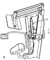
本開示の例示的実施形態は、以下の段落で説明される。図1Aから図1Mを参照すると、運動装置に設置された(例、組み込まれた、又は、後付けされた)本開示の機器102が図示される。実例として、図1Aから図1Mまでの運動装置は、レッグプレスマシン104である。レッグプレスマシン104は、負荷インターフェース106(例、プレスプレート)と、負荷インターフェース106に連結されるフレーム108とを具備する。レッグプレス運動中、運動する人110は通常、シート150に位置し、ハンドグリップ152を使用する。運動する人110は、図1C及び図1Dに図示される通り、負荷インターフェース106上に自身の足を置き、負荷インターフェース106を押す。
Illustrative embodiments of the present disclosure are described in the following paragraphs. With reference to FIGS. 1A to 1M, the
図示の通り、いくつかの実施形態では、機器102はリニア調整システム112を具備する。いくつかの実施形態では、機器112はまた、リニア調整システムの長さを調整するための、1つ又は複数のダイヤル、ハンドル、ノブ、グリップ、及びボタンといった、手動機構又は機械的機構を具備する。例として、図1Aから図1Mはダイヤル130を図示し、そのダイヤル130はリニア調整システムの長さを手動で調整するための、ダイヤル130から突出したハンドル132を有する。
As shown, in some embodiments, the
リニア調整システム112によって、機器102は、直線方向(例、長手方向)にその長さを調整し、様々な所望の長さでロックすることが可能となる。そういった様々な長さはそれぞれ、負荷インターフェース106の機能範囲の複数の機能位置の異なる機能位置に、運動装置の負荷インターフェース106を固定するように作用する。例えば、いくつかの実施形態では、リニア調整システム112が調整され、ロックされ得る10以上の異なる長さと、対応する負荷インターフェース106の10の、又は、異なる機能位置がある。したがって、一旦機器102がレッグプレスマシン104といった、選択した運動装置に設置されると、運動する人110は機器102によって、負荷インターフェース106に高負荷又は極力高い負荷を加えることができ、運動装置(例、レッグプレス装置)に関わる運動に関わる可動域全体の複数の位置のうちのいずれか1つにおいて、筋繊維を100%使用して限界まで行うことができる。
The
例えば、図1Cを参照すると、いくつかの実施形態では、運動する人110は、可動域で筋肉群に作用する運動を行う。いくつかの実施形態では、可動域は、運動する人によって加えられ得る第1最大力によって特徴付けられる第1サブ範囲を具備する。可動域はさらに、運動する人によって加えられ得る第2最大力によって特徴付けられる第2サブ範囲を具備する。第2最大力は、第1最大力より大きい。機器又は機器のリニア調整システムは、負荷インターフェース106の機能範囲の機能位置で負荷インターフェース106を固定し得る。例えば、機器又はリニア調整システムは、第2サブ範囲内となるように負荷インターフェース106を固定し得、ユーザーは、第2サブ範囲に到達するのに第1サブ範囲を経る必要はない。運動する人はそのような位置で、筋肉群が第1サブ範囲を経る必要なしに第2サブ範囲内にある、可動域内の一点にある状態で、負荷インターフェース106に力を加え得る。
For example, referring to FIG. 1C, in some embodiments, the exercising
図1Aを参照すると、負荷又は力が負荷インターフェース106に加えられると、負荷インターフェース106は次に、それに応じてリニア調整システム112に負荷又は力を加える。リニア調整システム112に加えられる力を測定するため、機器102は、リニア調整システム112に固定連結されるセンサ114を具備する。いくつかの実施形態では、センサ114は、リニア調整システム上に加えられる力に応じて信号(例、アナログ又はデジタル信号)を出力する。
Referring to FIG. 1A, when a load or force is applied to the
図1A及び図1Bを参照すると、いくつかの実施形態では、リニア調整システム112は、第1端116と第2端118とを有する。第1端116は、運動装置の負荷インターフェース106とフレーム108のうちの一方に固定接続されるよう構成される。センサ114は、第1側120と第2側122とを有する。いくつかの実施形態では、センサ114の第1側120は、図1Bに図示する通り、リニア調整システム112の第2端118に固定連結される。センサ114の第2側122は、運動装置の負荷インターフェース106とフレーム108のうちの他方に固定接続されるよう構成される。例えば、図1Aから図1Mに図示される実施形態では、センサ114の第2側122が運動装置のフレーム108に固定接続され、リニア調整システム112の第1端116が運動装置の負荷インターフェース106に固定接続される。
With reference to FIGS. 1A and 1B, in some embodiments, the
レッグプレスマシン104又は本開示におけるその他の運動装置に対する機器102の配置は、例示的なものであり、排他的なものではないことが理解されるだろう。機器102の長さは所望の通り調整され、ロックされ得るので、機器102が様々な機能位置で負荷インターフェース106を固定し得、負荷インターフェース106に加えられる負荷が(直接又は間接的に)測定され得る限り、機器102は様々な配置で運動装置に設置され、運動装置の様々な部品に接続され得る。例えば、リニア調整システムの第1端は、負荷インターフェース106ではなくフレームに固定接続され得るか、又は、様々なバー又はプレート、運動装置のその他の構造部品に接続され得る。
It will be appreciated that the placement of the
リニア調整システムの第1端116及びセンサ114の第2側122は、直接又は間接的に、運動装置の負荷インターフェース106又はフレームに接続され得ることが理解されるだろう。例えば、リニア調整システムの第1端とセンサ114の第2端は、コネクタ、プレート、ブラケット、又はバーのような、その他の部品を介して、運動装置の負荷インターフェース106又はフレームに間接接続され得る。実例として、図1Aから図1Mは、1つ又は複数のプレート140及びバー142を介して運動装置の負荷インターフェース106に間接接続された、リニア調整システム112の第1端116を図示する。
It will be appreciated that the
本開示の運動装置は例示的なものであり、排他的なものではないことがさらに理解されるだろう。リニア調整システム112によって、機器102は直線方向(例、長手方向)に装置の全体の寸法を調整できるため、機器102は様々な異なるタイプの運動装置に設置され得る。例として、図2Aは、異なるレッグプレスマシンと使用される装置を図示しており、その運動はレッグプレス運動である。本実施形態では、機器102はリニアアクチュエータ502と力センサ114とを具備し、リニアアクチュエータ502はリニア調整システム112として作用し、負荷インターフェース106に対してユーザーが負荷をかける位置を調整できるよう、レッグプレスマシンシートアセンブリ150の移動を可能にする。いくつかの実施形態では、アクチュエータ502の動きは、タッチスクリーン電子装置212(モニター機器)上に表示されるユーザーインターフェースによって管理され、そのタッチスクリーン電子装置212はまた、ロードセルセンサ114から、加えられた力について、図及び/又は数字によりフィードバックを提供する。
It will be further understood that the exercise devices of the present disclosure are exemplary and not exclusive. The
さらに明確にするため、図2Aのレッグプレスマシンに設置された状態で図示された機器の実施形態が、分離して図2Bに示される。ユーザーインターフェース及びデータディスプレイを具備するモニター機器212は、搭載型電子部品216に接続され、その搭載型電子部品216はアクチュエータを制御する電源切換回路を含む。いくつかの実施形態では、搭載型電子部品216はまた、リニアアクチュエータ502を駆動させて電子機器212に入電するのに適切な電圧を供給する電源変圧器を具備する。いくつかの実施形態では、搭載型電子部品216に接続する電力入力コード218が、アース設置された電源からシステム全体に電力を供給する。いくつかの実施形態では、力センサ114は、搭載型電子部品216に配線される。いくつかの実施形態では、力センサ信号は搭載型電子部品216によって処理され、配線接続によって電子機器212へ送信される。いくつかの実施形態では、電子機器212と搭載型電子部品516の間の通信はワイヤレスである。いくつかの実施形態では、電子機器212は、搭載型電子部品516から独立して入電される。
For further clarity, embodiments of the equipment illustrated while installed on the leg press machine of FIG. 2A are shown separately in FIG. 2B. The
図2Cは、図2Bに示す電子機器212の、いくつかの実施形態において表示されるユーザーインターフェースの一例として提供される。図2Cのユーザーインターフェースは、図2A及び図2Bに示すリニアアクチュエータ502の、延出を示すアフォーダンス814と、後退を示すアフォーダンス186とを具備する。いくつかの実施形態では、アフォーダンス814とアフォーダンス816は、図2Cに図示の通り、1つのスライドバーである。したがって、いくつかの実施形態では、1つの図形要素又は物理的なスイッチ(physical switch)が、アクチュエータ502の後退及び延出の両方を担い得る。アクチュエータ位置818もまた、図2Cの例示的インターフェースで示される。ユーザーの前回の、初回時、最良時、直近時の力発生820を示すデータが、ユーザーの力発生の瞬時値のグラフ822及び数値824の表示と共に提供される。本開示のいくつかの実施形態では、所定期間の任意の時間間隔(例、任意の連続5秒間、任意の連続10秒間、等)で現在の運動セッションにおける力発生の最高平均値を示すメトリック826が表示されるだろう。
FIG. 2C is provided as an example of a user interface displayed in some embodiments of the
図2Dは、運動を行うための負荷インターフェースと負荷インターフェースに連結されるフレームとを具備する運動装置からの入力データを処理するためのコンピュータシステム250を図示する。図2Dを参照すると、通常の実施形態では、コンピュータシステム250は、1つ又は複数の(CPUの)処理ユニット274と、ネットワーク又はその他の通信インターフェース284と、ユーザーインターフェース(例、いくつかの実施形態では、入力機器としての役割も果たすディスプレイ282を具備する)と、メモリ292(例、ランダムアクセスメモリ)と、上記部品を相互接続するための1つ又は複数の通信バス262と、上記部品に入電するための電源276と、を含む。メモリ292のデータは、キャッシングといった、既知のコンピューティング技術を使用して、不揮発性及び揮発性メモリ(図示なし)と途切れなく共有され得る。メモリ292は、中央処理ユニット274に対して離れて配置される大量記憶装置を具備し得る。つまり、メモリ292に記憶されたデータのいくつかは、実際にはコンピュータシステム250の外側にあるコンピュータに格納され得るが、インターネット、イントラネット、又は、ネットワークインターフェース284を使用するその他の形態のネットワーク又は電子ケーブルを介して、コンピュータシステムによって電子的にアクセスされ得る。分析コンピュータシステム250のメモリ92は、
・様々な基礎システムサービスを取扱う手順を具備するオペレーティングシステム290と、
・負荷インターフェースの機能範囲の複数の機能位置のうちのいずれか1つに運動装置の負荷インターフェース106を固定するリニア調整システム112に、ステップ関数命令を送るための機器コントローラモジュール292であって、リニア調整システム112が第1端116と第2端118とを含み、第1端116が運動装置の負荷インターフェース106とフレーム108のうちの一方に固定接続されるよう構成され、運動が可動域で対象者の筋肉群に作用し、可動域が対象者によって加えられ得る第1最大力によって特徴付けられる第1サブ範囲を具備し、可動域がさらに、対象者によって加えられ得る第2最大力によって特徴付けられる第2サブ範囲を具備し、第2最大力が第1最大力より大きく、リニア調整システムが、ステップ関数命令に応じて、筋肉群が、第1サブ範囲を経る必要なく、第2サブ範囲の可動域の一点にある状態で対象者が負荷インターフェースに力を加えることを可能にする、負荷インターフェースの機能範囲の位置に負荷インターフェースを固定する機器コントローラモジュール292と、
・センサ114からリニア調整システムに加えられる力の測定を得るための測定モジュール294であって、センサ114が、リニア調整システム112の第2端118に固定連結される第1側120と、負荷インターフェース106とフレーム108のうちの他方に固定接続されるよう構成される第2側122を含む測定モジュール294と、
・リニア調整システムにかかる測定力、又は、リニア調整システムにかかる測定力から算出される運動装置の負荷インターフェースに加えられる力、及び/又は、図2Cに図示する情報のいずれかをモニター機器に出力するためのディスプレイモジュール296と、を記憶する。
FIG. 2D illustrates a
-
A
A
-Outputs either the measuring force applied to the linear adjustment system, the force applied to the load interface of the exercise device calculated from the measuring force applied to the linear adjustment system, and / or the information shown in FIG. 2C to the monitor device. The
いくつかの実装態様では、コンピュータシステム250の上記のデータ要素又はモジュールのうちの1つ又は複数が、先に開示されたメモリ機器のうちの1つ又は複数に記憶され、上記の機能を行うための一式の命令に対応する。上述のデータ、モジュール、又はプログラム(例、命令の集合)は、別個のソフトウェアプログラム、手順、又はモジュールとして実装される必要はなく、よって、これらのモジュールの様々なサブ集合は、様々な実装において組み合わされるか、あるいは再配置され得る。いくつかの実装態様では、メモリ92は、上記のモジュール及びデータ構造のサブ集合を選択的に記憶する。さらに、いくつかの実施形態では、メモリ92は、上述されていない、さらに別のモジュール及びデータ構造を記憶する。
In some implementations, one or more of the above data elements or modules of the
いくつかの実施形態では、リニア調整システム112はリニアアクチュエータを含み、そのリニアアクチュエータの延出と後退は電力切換回路又はサーボモーターコントローラを含む周辺電子機器によって制御され、それによってリニア調整システムは、機器コントローラモジュール292によって提供されるステップ関数命令に応じて、リニア調整システムが負荷インターフェースを固定する、複数の機能位置における1つの機能位置に負荷インターフェースを移動させる。
In some embodiments, the
いくつかの実施形態では、コンピュータシステム250は、リニア調整システムにかかる測定力、又は、リニア調整システムにかかる測定力から算出される負荷インターフェースに加えられる力に基づいて、骨形成負荷(osteogenic loading)を決定する命令を記憶する。
In some embodiments, the
いくつかの実施形態では、コンピュータシステム250は、負荷インターフェースのための複数の機能位置の中の1つの機能位置をユーザーが選択することを可能にする、ディスプレイ上のアフォーダンス(例、図2Cの814/816)を与える命令を記憶する。さらに、そのアフォーダンスとのユーザー相互作用に応じて、機器コントローラモジュール292は、リニア調整システム112にステップ関数命令を送る。
In some embodiments, the
いくつかの実施形態では、ディスプレイモジュール296は、負荷インターフェース106の複数の機能位置の中の現在の機能位置を表示する。
In some embodiments, the
いくつかの実施形態では、ディスプレイモジュール296は、リニア調整システムによって固定される運動装置を使用した現在のセッションにおけるユーザーの現在の力出力と、(i)ユーザーが運動装置を使用した現在のセッション直前に運動装置を使用したセッションにおいて、同一ユーザーが生成した力の大きさ、(ii)運動装置を使用した以前のセッションで、ユーザーによって最高の力が達成されたセッション、及び(iii)運動装置を使用してユーザーが行った初回セッション、のうちのいずれかとの数値又はグラフによる比較を提供する。
In some embodiments, the
別の例として、図3は、チェストプレスマシン304と使用される機器102を図示し、運動はチェストプレス運動である。さらなる例として、図4は、コアマシン404と使用される機器102を図示し、運動は腹筋運動である。さらに別の例として、図5は、垂直リフトマシン504と使用される機器102を図示し、運動は垂直リフト運動である。
As another example, FIG. 3 illustrates a
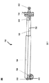
図3を参照すると、図1Aから図1Mのレッグプレスマシン104と同様、チェストプレスマシン304(図3)、コアマシン404(図4)、又は垂直リフトマシン504(図5)に対する機器102の配置は、例示的なものであり、排他的なものではない。さらに、図1Aから図1Mのレッグプレスマシン104と同様、機器102は任意の適切な位置に配置され得、チェストプレスマシン304、コアマシン404、又は垂直リフトマシン504の様々な部品に接続され得る。いくつかの実施形態では、機器102は、図2及び図3に図示する通り、運動装置内の油圧シリンダ又はウェイトスタックに置き換わる。いくつかの実施形態では、機器102は、図4に図示される運動装置の負荷インターフェース106のレバーアーム又は移動可能要素を固定する剛性ビームとして機能する。
Referring to FIG. 3, similar to the
いくつかの実施形態では、運動装置は調整可能なケーブルマシンであり、運動は、片腕ケーブルロウ、Vグリップケーブルロウ、クローズグリップ水平プルダウン、ニーリング水平プルダウン、フェイスプル外旋(face pule external rotation)、直立ローテーションチョップ、ケーブルクランチ、ハーフニーリングローテーションチョップ、ケーブルオーバーヘッドトライセプスエクステンション、片腕ケーブル水平上げ、30度水平プルダウン、ローププレスダウン、90度ケーブル外旋、背面片腕ケーブルカール、ニーリングローテーションチョップ、ケーブル外旋、ニーリングスタビリティリバースチョップ、ケーブルコアプレス、腕伸ばしプルダウン、ケーブルプレスダウン、直立ケーブルプルオーバー、着席ケーブルロウ、ハーフニーリングスタビリティチョップ、片腕ケーブルチェストプレス、直立サイドクランチ、フェイスプル、ケーブルフロント上げ、ニーリングオブリークケーブルクランチ、リバースグリップである。 In some embodiments, the exercise device is an adjustable cable machine, the exercise is one-arm cable row, V-grip cable row, closed grip horizontal pull-down, kneeling horizontal pull-down, face pull external rotation, Upright rotation chop, cable crunch, half kneeling rotation chop, cable overhead triceps extension, one arm cable horizontal raising, 30 degree horizontal pulldown, rope press down, 90 degree cable external rotation, rear one arm cable curl, kneeling rotation chop, cable external rotation, Kneeling Stability Reverse Chop, Cable Core Press, Arm Stretch Pulldown, Cable Press Down, Upright Cable Pullover, Seated Cable Row, Half Kneeling Stability Chop, One Arm Cable Chest Press, Upright Side Crunch, Face Pull, Cable Front Raise, Kneeling Oblique cable crunch, reverse grip.
負荷インターフェース106は、様々は形態をとり得る。例えば、負荷インターフェース106は、図1Aから図1Mに図示する通り1つ又は複数のレッグプレスプレート106と、図3に図示する通り1つ又は複数のチェストプレス負荷インターフェース306と、図3に図示する通り1つ又は複数のコアプル(core−pull)負荷インターフェース306と、図5に図示する通り1つ又は複数の垂直リフト負荷インターフェース506とを具備する。
The
いくつかの実施形態では、機器102はさらに、リニア調整システムにかかる測定力を、運動によって負荷インターフェース上に加えられる実際の力に相関させる相関機構を具備する。いくつかの実施形態では、相関機構は、表、チャート、曲線(curves)、多項式(polynomials)を含むがこれらに限らず、その2つの動作変数(operating variables)は、(i)センサ114によって検知される力の量と、(ii)リニア調整システム112の位置である。ある実施形態では、相関機構は、図9に図示される所定マスター表808のような、運動装置用の所定マスター表を具備する。所定マスター表808は、センサによって測定される力と、複数の機能位置の各機能位置及び測定した複数のウェイト力における各測定力の、負荷インターフェースに加えられる対応する実際の力との一式を具備する。いくつかの実施形態では、相関機構はセンサ114内に搭載される。例えば、いくつかの実施形態では、マスター表808は複数のセルを有し、各セルは、(i)センサ上の測定力と、(ii)機能位置、によってインデックスされる。さらに、セルは値を有し、この値はインデックス(i)及び(ii)に与えられる実際の力を表わす。
In some embodiments, the
次に図6から図8を参照すると、本開示のいくつかの実施形態における機器102の例示的リニア調整システムが図示される。これらの実施形態は図示のためのものであり、限定するためのものではないことが理解されるだろう。その他のシステム、機構、構造は、そういったシステム、機構、構造によって運動装置の負荷インターフェースを調整しやすくし、負荷インターフェースの機能範囲において様々な機能位置で運動装置の負荷インターフェースをロックしやすくすることを条件として使用され得る。
Next, with reference to FIGS. 6-8, an exemplary linear adjustment system for
図6に示す通り、いくつかの実施形態では、リニア調整システムはリニアアクチュエータ502である。リニアアクチュエータ502は、固定部分504と、その固定部分に軸方向に整列した延出可能部分506とを具備する。延出可能部分506は、リニアアクチュエータ502の長手方向に、固定部分504に対して移動可能である。ある実施形態では、固定部分504と延出可能部分506は同心である。別の実施形態では、固定部分504と延出可能部分506は同心であり、実質的に同一の断面形状を有する。いくつかの実施形態では、延出可能部分は、固定部分よりも小さい呼び径を有する。一実施形態では、固定部分は中空であり、延出可能部分は固定部分内に摺動可能に配置される。
As shown in FIG. 6, in some embodiments, the linear adjustment system is a
リニアアクチュエータ502はさらに、固定部分に対して選択した位置で延出可能部分をロックするロック機構508を具備する。ロック機構508は、電気、空気圧、油圧によって、又は機械的に作動される。
The
いくつかの実施形態では、機器102は、1つ又は複数のコネクタを具備する。例えば、図6は、第1コネクタ510と第2コネクタ512とを具備する機器102を図示する。第1コネクタ510は、リニア調整システムの第1端又は第2端を運動装置の負荷インターフェース又はフレームに固定接続するため、リニア調整システム(例、リニアアクチュエータ502)のその端に配置される。実例として、図5は、リニア調整システムの第2端118に配置された第1コネクタ510を示し、図1Aから図1Mは、リニア調整システムの第1端116に配置された第1コネクタを示す。第2コネクタ512は、センサ114の第2側122を運動装置の負荷インターフェース又はフレームに固定接続するため、センサ114の第2側122上に配置される。いくつかの実施形態では、第1コネクタ510及び/又は第2コネクタ512は、タング(tang)、クレビス(clevis)、クランプ、締め具、ピン、ネジ、ボルト、リング、等である。いくつかの実施形態では、機器102はさらに、リニア調整システムとセンサとの間に配置される第3コネクタ514具備する。第3コネクタ514は、リニア調整システムの他方端をセンサ114の第1側120に固定接続する。
In some embodiments, the
図1Aから図5に戻って参照すると、いくつかの実施形態では、リニア調整システム112の第1端116の、負荷インターフェース106又はフレーム108への接続は、負荷インターフェース106又はフレーム108から延出する運動装置内の1つ又は複数の部品にリニア調整システムの第1端を接続させることによって達成される。例えば、図1Aから図5は、負荷インターフェース106又はフレーム108から延出する、運動装置内の1つ又は複数のプレート及び/又はバー(例、140、142、410、510)を介した接続を図示する。同様に、いくつかの実施形態では、センサ114の第2側122の、負荷インターフェース又はフレームへの接続は、センサ114の第2側122を、負荷インターフェース又はフレームから延出する、運動装置内の1つ又は複数の部品に接続することによって達成される。例えば、図3から図5は、負荷インターフェース又はフレームから延出する、運動装置内の1つ又は複数のバー又はプレート(例、308、408、508)を介した接続を図示する。
With reference to FIG. 1A back to FIG. 5, in some embodiments, the connection of the
図7を参照すると、いくつかの実施形態では、リニア調整システムは、クランク駆動機構システム702である。リニアアクチュエータ502と同様、クランク駆動機構システム702は、固定部分704と、固定部分704に軸方向に整列した延出可能部分706とを具備する。延出可能部分706は、固定部分704に対してクランク駆動機構システム702の長手方向に移動可能である。一実施形態では、固定部分704は中空であり、延出可能部分は固定部分に摺動可能に配置される。
Referring to FIG. 7, in some embodiments, the linear adjustment system is a crank
駆動機構システム702はさらに、延出可能部分706を固定部分704に対して選択した位置にロックするロック機構708を具備する。いくつかの実施形態では、ロック機構708は、リニア調整システムの長手方向に沿って固定部分704に対して延出可能部分706を手動で移動させ、それによってクランク駆動機構システム702の長さを調整するハンドル、ノブ、ダイヤル、等710を具備する。
The
図8を参照すると、いくつかの実施形態では、リニア調整システムは、手動調整可能ピンシステム850である。リニアアクチュエータ502及びクランク駆動機構システム702と同様、手動調整可能ピンシステム850は、固定部分852と、固定部分に軸方向に沿って整列した延出可能部分856とを具備する。延出可能部分856は、手動調整可能ピンシステム850の長手方向に、固定部分852に対して移動可能である。一実施形態では、固定部分852は中空であり、延出可能部分856は固定部分852内で摺動可能に配置される。
Referring to FIG. 8, in some embodiments, the linear adjustment system is a manually
いくつかの実施形態では、手動調整可能ピンシステム850はさらに、固定部分852に対して選択した位置で延出可能部分856をロックするロック機構を具備する。ロック機構は、固定部分856の壁部に形成された穴部860と、延出部分856の壁部に形成され、リニア調整システムの長手方向に互いに離間した複数の穴部862とを具備する。ロック機構はさらに、固定部分852上の穴部860を延出可能部分856上の複数の穴部862のうちのいずれか1つに係合させ、固定部分852に対して延出可能部分856をロックするよう構成された締め具864を具備する。
In some embodiments, the manually
実例として、図8は、固定部分に形成された1つの実質的に円形の穴部と、延出可能部分上の7つの実質的に円形の穴部を示す。固定部分及び延出可能部分上の穴部の構成(例、サイズ、形状、穴の数、固定部分又は延出可能部分上の穴の位置)は容易に変更可能であることが理解されるだろう。例えば、固定部分及び延出可能部分上の穴部は、円形、楕円形、四角形、多角形、細長形、又は任意の好適な形状を様々なサイズで有し得る。別の例として、固定部分は、2つ以上の穴を有して形成され得る。 As an example, FIG. 8 shows one substantially circular hole formed in the fixed portion and seven substantially circular holes on the extendable portion. It is understood that the configuration of the holes on the fixed and extendable parts (eg, size, shape, number of holes, position of holes on the fixed or extendable part) can be easily changed. Let's do it. For example, the holes on the fixed and extendable portions can have a circular, oval, quadrangular, polygonal, elongated, or any suitable shape in various sizes. As another example, the fixed portion can be formed with two or more holes.
いくつかの実施形態では、リニア調整システム(例、リニアアクチュエータ502、クランク駆動機構システム602、又は手動調整可能ピンシステム702)の長さは、5センチメートルから1200センチメートル、10センチメートルから1000センチメートル、30センチメートルから500センチメートルまで延出可能な長さを有する。この範囲は、運動マシンの特徴によって変わることが理解されるだろう。
In some embodiments, the length of the linear adjustment system (eg,
いくつかの実施形態では、リニア調整システム(例、リニアアクチュエータ502、クランク駆動機構システム702、又は手動調整可能ピンシステム850)は、リニア調整システムの長さ、さらには機器102の長さが継続的に調整可能となるように構成される。いくつかの実施形態では、リニア調整システムは、リニア調整システムの長さ、さらには機器の長さが、増加量毎に段階的に調節可能となるよう構成される。いくつかの実施形態では、増加量は固定量であり、0.3インチから0.5インチの間、0.5インチから1.0インチの間、1.0インチから1.5インチの間、1.5インチから2.0インチの間、2.0インチから2.5インチの間、2.5インチから3.0インチの間、3.0インチから3.5インチの間、3.5インチから4.0インチの間、4.0インチから4.5インチの間、4.5インチから5.0インチの間、又はそれらのSI単位系同等量である。いくつかの実施形態では、増加量は固定量であり、1センチメートルから2センチメートルの間、2センチメートルから3センチメートルの間、3センチメートルから4センチメートルの間、4センチメートルから5センチメートルの間、5センチメートルから6センチメートルの間、6センチメートルから7センチメートルの間、7センチメートルから8センチメートルの間、8センチメートルから9センチメートルの間、9センチメートルから10センチメートルの間、10センチメートルから11センチメートルの間である。
In some embodiments, the linear adjustment system (eg,
次に図9を見ると、本開示のいくつかの実施形態における機器102のセンサ114を図示した略図が示される。図示の通り、いくつかの実施形態では、センサ114は、リニア調整システムに加えられる力に従ってアナログ信号を出力するロードセル902を具備する。ある実施形態では、ロードセル902は、歪みゲージロードセルを具備する。いくつかの実施形態では、センサ114はまた、アナログ信号をデジタル信号に変換する電子回路904を具備する。いくつかの実施形態では、センサ114はさらに、デジタル信号を出力するポートを具備する。いくつかの実施形態では、電子回路はアナログ信号をUSB対応型デジタル信号に変換し、ポートはUSBポートである。
Next, looking at FIG. 9, a schematic diagram illustrating the
いくつかの実施形態では、相関機構は、リニア調整システムにかかる測定力を運動によって負荷インターフェースに加えられる実際の力に相関させるマスター表を具備する。マスター表は、その運動装置、又は様々な運動装置用に予め定められている。いくつかの実施形態では、マスター表908のようなマスター表は、図9に図示の通り、センサ114内に記憶又は搭載される。いくつかの実施形態では、所定マスター表908は、センサ114によって測定される力と、複数の機能位置の各機能位置と複数のウェイト中の各ウェイトに対して負荷インターフェースに加えられる、対応する力との一式を具備する。
In some embodiments, the correlation mechanism comprises a master table that correlates the measured force applied to the linear adjustment system with the actual force applied to the load interface by motion. The master table is predetermined for that exercise device, or various exercise devices. In some embodiments, a master table, such as the master table 908, is stored or mounted within the
いくつかの実施形態では、所定マスター表908では、負荷インターフェースの複数の機能位置は、固定の増加量で機器の長さ又はリニア調整システムの長さに対応しており、その固定の増加量とは、0.3インチから0.5インチの間、0.5インチから1.0インチの間、1.0インチから1.5インチの間、1.5インチから2.0インチの間、2.0インチから2.5インチの間、2.5インチから3.0インチの間、3.0インチから3.5インチの間、3.5インチから4.0インチの間、4.0インチから4.5インチの間、又は、4.5インチから5.0インチの間である。 In some embodiments, in the predetermined master table 908, the plurality of functional positions of the load interface correspond to the length of the device or the length of the linear adjustment system with a fixed increase, with that fixed increase. Between 0.3 inches and 0.5 inches, between 0.5 inches and 1.0 inches, between 1.0 inches and 1.5 inches, between 1.5 inches and 2.0 inches, 2. Between 2.0 inches and 2.5 inches, between 2.5 inches and 3.0 inches, between 3.0 inches and 3.5 inches, between 3.5 inches and 4.0 inches 4. It is between 0 inches and 4.5 inches, or between 4.5 inches and 5.0 inches.
いくつかの実施形態では、所定マスター表908では、複数のウェイトにおけるウェイトの増加は変化する。いくつかの実施形態では、所定マスター表908では、複数のウェイトにおけるウェイト増加は固定量であり、その固定量は、1ポンドから5ポンドの間、5ポンドから10ポンドの間、10ポンドから20ポンドの間、20ポンドから30ポンドの間、30ポンドから40ポンドの間、又は、40ポンドから50ポンドの間である。いくつかの実施形態では、所定マスター表908では、複数のウェイトにおけるウェイト増加は固定量であり、その固定量は、1キログラムから5キログラムの間、5キログラムから10キログラムの間、10キログラムから20キログラムの間、20キログラムから30キログラムの間、30キログラムから40キログラムの間、又は、40キログラムから50キログラムの間である。 In some embodiments, in the predetermined master table 908, the weight increase at multiple weights varies. In some embodiments, in the predetermined master table 908, the weight increase at multiple weights is a fixed amount, the fixed amount being between 1 pound and 5 pounds, between 5 pounds and 10 pounds, and 10 pounds to 20 pounds. Between pounds, between 20 and 30 pounds, between 30 and 40 pounds, or between 40 and 50 pounds. In some embodiments, in the predetermined master table 908, the weight increase at multiple weights is a fixed amount, the fixed amount being between 1 kilogram and 5 kilograms, between 5 kilograms and 10 kilograms, and 10 kilograms to 20 kilograms. Between kilograms, between 20 and 30 kilograms, between 30 and 40 kilograms, or between 40 and 50 kilograms.
いくつかの実施形態では、センサ114はさらに、所定マスター表908を使用して、運動する人によってリニア調整システムに加えられる力と負荷インターフェースの機能位置に基づいて、負荷インターフェースに加えられる力を決定するプロセッサ910を具備する。
In some embodiments, the
いくつかの実施形態では、センサ114は電子機器912に電気的に、又はワイヤレスに接続される。センサ114は、測定したリニア調整システムにかかる力と、運動装置の負荷インターフェースにかかる力と、又はその両方を電子機器912に出力する。いくつかの実施形態では、電子機器912は、ディスプレイ、スマートフォン、コンピュータ、サーバー、レシーバー、又はその他の電子機器やシステムである。実例として、図1Eは、ケーブル134を介して電子機器136(例、ディスプレイ、モニター、又はスクリーン)に接続されたセンサ114を図示する。いくつかの実施形態では、電子機器は以下の、 (i)リニア調整システムにかかる測定力、負荷インターフェースに加えられる力、又は両方の力を表示し、(ii)リニア調整システムにかかる測定力及び負荷インターフェースに加えられる力のうちの1つ又は複数に基づいて骨形成負荷を決定することのうちの一つ以上を行う。本明細書で使用される用語「骨形成負荷(osteogenic loading )」は、最適な機能位置と最適な機能位置に印加される極力高い負荷のことである。
In some embodiments, the
リニア調整システムがリニアアクチュエータである実施形態のような、リニア調整機構が電気制御されるいくつかの実施形態では、請求項に関わる発明は、図2A、図2B、図3、図4、図5に図示される通り、アクチュエータ502を制御する、図10にあるようなシステムを具備する。いくつかの実施形態では、そのコントロールシステムは、アナログ又はデジタル出力ピン1022を使用して電流を直接管理し、1つ又は複数の電流制御電源切換機構1024を作動又は作動解除させる、マイクロコントローラ、プロセッサ、システムオンチップ(System On a Chip)、コンピュータ1020を具備し、その電流制御電源切換機構1024は、電気機械式リレー、ソリッドステートリレー、MOSFETS、HブリッジMOSFET、パワートランジスタ、ダーリントントランジスタ、サイリスタ、もしくは、前述又は同様の機器の任意の組み合わせから成る。いくつかの実施形態では、電力切換部品1024を変調させるのに使用する信号出力1022は、電流制限抵抗器1026を発揮させ、過度の電流引き込みからプロセッサ1020のデジタル又はアナログ出力を保護する。
In some embodiments in which the linear adjustment mechanism is electrically controlled, such as an embodiment in which the linear adjustment system is a linear actuator, the claimed invention comprises FIGS. 2A, 2B, 3, 4, 4, and 5. As illustrated in FIG. 10, it comprises a system as shown in FIG. 10 that controls the
リニア調整機構がリニアアクチュエータ502である本開示のいくつかの実施形態では、そのアクチュエータは、延出の程度を示すアナログ信号を提供するようにアクチュエータ内に組み込まれた電位差計1028を有する。いくつかの実施形態では、プロセッサ1020は、ポテンショメータからのアナログ入力1030を受容し、正確な調整と、アクチュエータ502の位置の表示を可能にする。いくつかの実施形態は、第1指令ローパスフィルタ1032などにより、この信号のハードウェアフィルタリング又は任意の同様の機能ハードウェア信号条件付け技術を組み込む。
In some embodiments of the present disclosure where the linear adjustment mechanism is a
いくつかの実施形態では、プロセッサ1020は、アクチュエータの動きを管理し、ロードセルの出力を読み込み、必要データをスクリーンに映し、タッチスクリーン、ハードウェアボタン、他を介してユーザーからのコマンドを受容する能力のある、搭載型のコンピュータ又は高性能なマイクロコントローラを具備する。
In some embodiments, the
いくつかの実施形態では、プロセッサ1020は、図2Bに図示される812のようなマスター電子機器に対してスレーブ機器又は周辺機器として動作するローパワーマイクロコントローラである。いくつかの実施形態では、図10に図示されるプロセッサ1020は、ケーブルによってマスター機器に接続される。その他の実施形態では、プロセッサ1020は、ワイヤレストランシーバ1034に接続されるか、ワイヤレストランシーバ1034を組み込み、そのワイヤレストランシーバ1034は、ブルートゥース、RF、WiFi、又は同様のワイヤレスプロトコルを使用して、マスター機器と通信する。いくつかの実施形態では、マスター機器は運動マシンの部品であり、いくつかの実施形態では、ユーザーが所有し、プロセッサ1020に一時的にペアリングされ、プロセッサ1020を制御するのに使用されるタブレット、スマートフォン、ノートパソコンのような、多目的電子機器であってもよい。いくつかの実施形態では、プロセッサ1020はアクチュエータを制御し、力センサによって生成されるデジタル又はアナログ信号を受容する。いくつかの実施形態では、プロセッサ1020は、力センサからの信号を増幅させ、フィルタリングし、翻訳し、マスター電子機器に提供する。
In some embodiments, the
いくつかの実施形態では、アクチュエータ502とその電位差計1028以外の、図10で説明される回路全体は、図2Bに示す搭載型電子機器筐体516に記憶される。
In some embodiments, the entire circuit described in FIG. 10, other than the
本明細書の引用文献は全て、まるで、各刊行物、特許、又は特許出願が、具体的に及び個々に示され、全ての目的のためにその全体が参照として組み込まれるかのように、同じ程度までその全体が参照として、全ての目的のために本明細書に組み込まれる。 All references cited herein are the same, as if each publication, patent, or patent application is presented specifically and individually and incorporated in its entirety for all purposes as a reference. To a degree, the whole is incorporated herein by reference for all purposes.
本発明は、非一時的コンピュータ可読記憶媒体に搭載されるコンピュータプログラム機構を含むコンピュータプログラム製品として実装され得る。例えば、コンピュータプログラム製品は、図2Dに示されるプログラムモジュールを含み得る。これらのプログラムモジュールは、CD−ROM、DVD、磁気ディスク記憶製品、又はその他の任意の非一時的コンピュータ可読データ又はプログラム記憶製品に記憶され得る。 The present invention may be implemented as a computer program product comprising a computer program mechanism mounted on a non-temporary computer readable storage medium. For example, a computer program product may include the program module shown in FIG. 2D. These program modules may be stored on a CD-ROM, DVD, magnetic disk storage product, or any other non-temporary computer-readable data or program storage product.
本発明の多くの修正及び変形は、その趣旨及び範囲から逸脱することなく成され得ることが当業者には明らかであろう。本明細書に記載の特定の実施形態は、例示のためにのみ提供される。実施形態は、本発明の原理とその実際的な用途を最良に説明し、それによって当業者が本発明と様々な実施形態を、企図される特定の用途に適するように様々な修正を行って利用できるように、選択され、説明された。本発明は、このような特許請求の範囲が権利を持つ等価物の全範囲と共に、添付の特許請求の範囲の条件によってのみ制限されるべきである。 It will be apparent to those skilled in the art that many modifications and modifications of the present invention can be made without departing from the spirit and scope thereof. The particular embodiments described herein are provided for illustration purposes only. The embodiments best describe the principles of the invention and its practical uses, whereby those skilled in the art will make various modifications to the invention and various embodiments to suit the particular application intended. Selected and described for use. The present invention should be limited only by the terms of the appended claims, along with the full scope of the equivalents to which such claims are entitled.
Claims (40)
前記運動装置の前記負荷インターフェースの初期位置を、前記負荷インターフェースの機能範囲の複数の機能位置のいずれか1つに固定するように構成されているリニア調整システムであって、前記機能範囲は、第1の末端機能位置、一つ以上の中間位置、及び第2の末端機能位置を含み、
前記リニア調整システムが第1端と第2端とを備え、前記第1端が前記運動装置の前記負荷インターフェースと前記フレームのうちの一方に固定接続されるよう構成される、リニア調整システムと、
前記リニア調整システムの前記第2端に固定連結される第1側と、前記負荷インターフェースと前記フレームのうちの他方に固定接続されるよう構成された第2側とを備えるセンサであって、
前記センサが、前記リニア調整システムにかかる力を測定し、前記リニア調整システムに加えられる前記力に応じて信号を出力する、センサと、を備え、
前記運動が可動域で対象者の筋肉群に作用し、前記可動域が前記対象者によって加えられ得る第1最大力によって特徴づけられる第1サブ範囲を具備し、
前記可動域が、前記対象者によって加えられ得る第2最大力によって特徴づけられる第2サブ範囲をさらに具備し、
前記第2最大力が前記第1最大力より大きく、
前記負荷インターフェースの前記初期位置は、前記筋肉群が前記第1サブ範囲を経る必要なく前記第2サブ範囲内にある前記可動域内の一点にある状態で、前記対象者が力を前記負荷インターフェースに加えることを可能にする、前記負荷インターフェースの前記機能範囲の位置であり、
前記負荷インターフェースは、前記第1のサブ範囲全体を通じてよりも、前記第2のサブ範囲全体を通じて前記第1の末端機能位置からより離れている、機器。 A device for an exercise device, comprising a load interface for the exercise device to perform exercise and a frame connected to the load interface, wherein the device is
A linear adjustment system configured to fix the initial position of the load interface of the exercise device to any one of a plurality of functional positions of the functional range of the load interface , wherein the functional range is the first. Includes one terminal functional position, one or more intermediate positions, and a second terminal functional position.
A linear adjustment system comprising a first end and a second end, the first end being fixedly connected to one of the load interface of the exercise device and the frame.
A sensor comprising a first side fixedly connected to the second end of the linear adjustment system and a second side configured to be fixedly connected to the other of the load interface and the frame.
The sensor comprises a sensor that measures the force applied to the linear adjustment system and outputs a signal according to the force applied to the linear adjustment system.
The movement acts on the subject's muscle groups in the range of motion, and the range of motion comprises a first subrange characterized by a first maximum force that can be applied by the subject.
The range of motion further comprises a second subrange characterized by a second maximum force that can be applied by the subject.
The second maximum force is larger than the first maximum force,
The initial position of the load interface is such that the subject exerts a force on the load interface while the muscle group is at one point in the movable range within the second sub range without having to go through the first sub range. The location of the functional range of the load interface that allows it to be added.
A device in which the load interface is more distant from the first terminal functional position throughout the second subrange than through the entire first subrange .
固定部分と、
前記固定部分に軸方向に整列した延出可能部分であって、前記固定部分に対して直線方向に移動可能な延出可能部分と、
前記固定部分に対して選択した位置で前記延出可能部分をロックするロック機構と、を備える、請求項1に記載の機器。 The linear adjustment system
Fixed part and
An extendable portion that is axially aligned with the fixed portion and that can move in a linear direction with respect to the fixed portion.
The device according to claim 1, further comprising a locking mechanism that locks the extendable portion at a position selected with respect to the fixed portion.
前記延出可能部分が、延出部分の壁部上に形成され、前記リニア調整システムの前記直線方向に、互いに離間した複数の穴部を有し、
前記ロック機構が、前記固定部分上の前記穴部を前記延出可能部分上の前記複数の穴部に係合させ、前記固定部分に対して前記延出可能部分をロックするよう構成される締め具を備え、前記複数の穴部の各穴部が、前記負荷インターフェースの前記複数の機能位置の中の1つの機能位置に独自に対応する、請求項14に記載の機器。 The fixed portion has a hole formed on the wall portion of the fixed portion.
The extendable portion is formed on the wall portion of the extendable portion and has a plurality of holes separated from each other in the linear direction of the linear adjustment system.
The locking mechanism is configured to engage the hole on the fixed portion with the plurality of holes on the extendable portion and lock the extendable portion against the fixed portion. The device according to claim 14, wherein each hole of the plurality of holes uniquely corresponds to one functional position among the plurality of functional positions of the load interface.
前記センサの前記第2側を前記負荷インターフェースと前記フレームのうちの他方に固定接続させる第2コネクタと、
前記リニア調整システムの前記第2端を前記センサの前記第1側に固定接続させる第3コネクタと、のうちの1つ又は複数をさらに備える、請求項1に記載の機器。 A first connector that fixedly connects the first end of the linear adjustment system to one of the load interface and the frame.
A second connector that fixedly connects the second side of the sensor to the load interface and the other of the frames.
The device according to claim 1, further comprising one or more of a third connector for fixing the second end of the linear adjustment system to the first side of the sensor.
前記リニア調整システムに加えられる力に応じてアナログ信号を出力するロードセルと、
前記アナログ信号をデジタル信号に変換するための電子回路と、
前記デジタル信号を出力するポートと、を備える、請求項1に記載の機器。 The sensor
A load cell that outputs an analog signal according to the force applied to the linear adjustment system, and
An electronic circuit for converting the analog signal into a digital signal,
The device according to claim 1, further comprising a port for outputting the digital signal.
前記モニター機器が、前記リニアアクチュエータの延出及び後退を制御する電源切換回路又はサーボモーターコントローラを備える周辺電子機器を備えるか、又は連動して作動し、それによって、前記リニア調整システムが、前記複数の機能位置の、前記リニア調整システムが前記負荷インターフェースを固定する機能位置に前記負荷インターフェースを移動させる、請求項32に記載の機器。 The linear adjustment system includes a linear actuator.
The monitor device comprises or interlocks with a peripheral electronic device including a power switching circuit or a servomotor controller that controls extension and retreat of the linear actuator, whereby the linear adjustment system comprises the plurality. 32. The device of claim 32, wherein the linear adjustment system moves the load interface to a functional position where the load interface is fixed.
(i)前記ユーザーが前記機器を使用した現在のセッション直前に前記機器を使用したセッションにおいて、同一ユーザーが生成した力の大きさ、(ii)前記機器を使用した以前のセッションで、前記ユーザーによって最高の力が達成されたセッション、及び(iii)前記機器を使用して前記ユーザーが行った初回セッション、のうちのいずれかとの数値又はグラフによる比較を提供する、請求項30に記載の機器。 The monitor device outputs the user's current force in the current session using the device.
(I) The magnitude of the force generated by the same user in the session using the device immediately before the current session in which the user used the device, (ii) by the user in the previous session using the device. 30. The device of claim 30, which provides a numerical or graphical comparison with any of the session in which the highest force was achieved and (iii) the first session performed by the user using the device.
前記センサの前記第2側が、第2コネクタを介して前記運動装置の前記負荷インターフェース及び前記フレームのうちの他方に固定接続される、請求項1に記載の機器。 The first end is fixedly connected to one of the load interface of the exercise device and the frame via a first connector.
The device according to claim 1, wherein the second side of the sensor is fixedly connected to the load interface of the exercise device and the other of the frames via a second connector.
Priority Applications (1)
| Application Number | Priority Date | Filing Date | Title |
|---|---|---|---|
| JP2021066731A JP7098018B2 (en) | 2015-09-18 | 2021-04-09 | Exercise equipment |
Applications Claiming Priority (5)
| Application Number | Priority Date | Filing Date | Title |
|---|---|---|---|
| US14/859,085 | 2015-09-18 | ||
| US14/859,085 US20170080287A1 (en) | 2015-09-18 | 2015-09-18 | Devices for exercise apparatuses |
| US201662329999P | 2016-04-29 | 2016-04-29 | |
| US62/329,999 | 2016-04-29 | ||
| PCT/US2016/052302 WO2017049198A1 (en) | 2015-09-18 | 2016-09-16 | Devices for exercise apparatuses |
Related Child Applications (1)
| Application Number | Title | Priority Date | Filing Date |
|---|---|---|---|
| JP2021066731A Division JP7098018B2 (en) | 2015-09-18 | 2021-04-09 | Exercise equipment |
Publications (3)
| Publication Number | Publication Date |
|---|---|
| JP2018534954A JP2018534954A (en) | 2018-11-29 |
| JP2018534954A5 JP2018534954A5 (en) | 2019-10-24 |
| JP6868012B2 true JP6868012B2 (en) | 2021-05-12 |
Family
ID=58289651
Family Applications (2)
| Application Number | Title | Priority Date | Filing Date |
|---|---|---|---|
| JP2018513314A Active JP6868012B2 (en) | 2015-09-18 | 2016-09-16 | Exercise equipment |
| JP2021066731A Active JP7098018B2 (en) | 2015-09-18 | 2021-04-09 | Exercise equipment |
Family Applications After (1)
| Application Number | Title | Priority Date | Filing Date |
|---|---|---|---|
| JP2021066731A Active JP7098018B2 (en) | 2015-09-18 | 2021-04-09 | Exercise equipment |
Country Status (7)
| Country | Link |
|---|---|
| US (2) | US11826611B2 (en) |
| EP (1) | EP3349867A4 (en) |
| JP (2) | JP6868012B2 (en) |
| CN (2) | CN112007338A (en) |
| AU (1) | AU2016324150B2 (en) |
| HK (1) | HK1258846A1 (en) |
| WO (1) | WO2017049198A1 (en) |
Families Citing this family (6)
| Publication number | Priority date | Publication date | Assignee | Title |
|---|---|---|---|---|
| CN112007338A (en) * | 2015-09-18 | 2020-12-01 | 贾奎什生物医学公司 | Apparatus for an exercise device |
| CN109758734A (en) * | 2019-01-03 | 2019-05-17 | 华中科技大学 | A kind of multi-mode Ergometric training device and method with muscular strength feedback function |
| JP2020108665A (en) * | 2019-01-07 | 2020-07-16 | 一雄 比嘉 | Load generating device for training and usage of the same |
| CN110038257A (en) * | 2019-04-26 | 2019-07-23 | 漳州卫生职业学院 | A kind of exercise load test macro |
| US11607582B2 (en) | 2021-06-04 | 2023-03-21 | Frame Innovative Technologies Corp. | Pilates reformer |
| CN113350750A (en) * | 2021-06-16 | 2021-09-07 | 浙江省肿瘤医院 | Nursing device suitable for breast cancer postoperative |
Family Cites Families (65)
| Publication number | Priority date | Publication date | Assignee | Title |
|---|---|---|---|---|
| US4466610A (en) | 1981-07-07 | 1984-08-21 | Israel Terry P | Exercise club |
| US4556214A (en) | 1982-09-14 | 1985-12-03 | Wright State University | Method and apparatus for exercising |
| US4571682A (en) | 1983-08-22 | 1986-02-18 | Computerized Sports Equipment, Inc. | System and method for skill enhancement and behavior modification |
| US5103404A (en) | 1985-12-06 | 1992-04-07 | Tensor Development, Inc. | Feedback for a manipulator |
| US5004230A (en) * | 1988-08-25 | 1991-04-02 | Arthur Jones | Method and apparatus for exercising or testing rotary torso muscles |
| USRE35598E (en) | 1988-11-28 | 1997-09-02 | Sadoff; Armin M. | Strength analyzer and method of using same |
| US5011142A (en) * | 1989-11-20 | 1991-04-30 | Christopher Eckler | Exercise control system |
| JPH03165744A (en) | 1989-11-22 | 1991-07-17 | Konbi Kk | Instantaneous force measuring device by leg extending force |
| US5244441A (en) * | 1990-01-31 | 1993-09-14 | Loredan Biomedical, Inc. | Position-based motion controller |
| US5052375A (en) | 1990-02-21 | 1991-10-01 | John G. Stark | Instrumented orthopedic restraining device and method of use |
| US5403251A (en) * | 1993-06-04 | 1995-04-04 | Chattanooga Group, Inc. | Patient positioning system and method for computer controled muscle exercising machine |
| US5569120A (en) | 1994-06-24 | 1996-10-29 | University Of Maryland-Baltimore County | Method of using and apparatus for use with exercise machines to achieve programmable variable resistance |
| US5830116A (en) | 1994-10-20 | 1998-11-03 | Gautier; Kenneth Bryan | Multiexercise weight lifting machine |
| US6515593B1 (en) | 1995-02-15 | 2003-02-04 | Izex Technologies, Inc. | Communication system for an instrumented orthopedic restraining device and method therefor |
| US5890996A (en) | 1996-05-30 | 1999-04-06 | Interactive Performance Monitoring, Inc. | Exerciser and physical performance monitoring system |
| US5722921A (en) | 1997-02-06 | 1998-03-03 | Cybex International, Inc. | Range limiting device for exercise equipment |
| US6050924A (en) | 1997-04-28 | 2000-04-18 | Shea; Michael J. | Exercise system |
| US6582342B2 (en) | 1999-01-12 | 2003-06-24 | Epm Development Systems Corporation | Audible electronic exercise monitor |
| US6872187B1 (en) | 1998-09-01 | 2005-03-29 | Izex Technologies, Inc. | Orthoses for joint rehabilitation |
| US6616579B1 (en) | 1999-06-14 | 2003-09-09 | Sensorpad Systems, Inc. | Apparatus for isometric exercise |
| US6159131A (en) | 1999-07-26 | 2000-12-12 | Aerobics And Fitness Association Of America | Fitnesstriage system and method |
| US20050107726A1 (en) | 1999-08-25 | 2005-05-19 | Oyen Duane P. | Remote monitoring of an instrumented orthosis |
| US7189190B2 (en) | 2000-03-10 | 2007-03-13 | Nautilus, Inc. | Group program for resistance exercise training |
| US6643385B1 (en) | 2000-04-27 | 2003-11-04 | Mario J. Bravomalo | System and method for weight-loss goal visualization and planning and business method for use therefor |
| US6746371B1 (en) | 2000-04-28 | 2004-06-08 | International Business Machines Corporation | Managing fitness activity across diverse exercise machines utilizing a portable computer system |
| US6436058B1 (en) | 2000-06-15 | 2002-08-20 | Dj Orthopedics, Llc | System and method for implementing rehabilitation protocols for an orthopedic restraining device |
| EP1166826A1 (en) * | 2000-06-19 | 2002-01-02 | Bet4000 S.R.L. | Physical training device |
| US6635013B2 (en) | 2000-12-11 | 2003-10-21 | Aerobics And Fitness Association Of America | Fitness triage system and exercise gets personal |
| US6561951B2 (en) | 2000-12-21 | 2003-05-13 | Agere Systems, Inc. | Networked biometrically secured fitness device scheduler |
| JP2002263213A (en) | 2001-03-08 | 2002-09-17 | Combi Corp | Training apparatus operation system and its method |
| US20030013071A1 (en) | 2001-07-03 | 2003-01-16 | Thomas Richard Todd | Computerized exercise apparatus |
| US6746370B1 (en) | 2001-09-27 | 2004-06-08 | Meridian Asset Management Inc. | Method, apparatus and data processor program product capable of enabling administration of a levels-based athleticism development program |
| MXPA02004029A (en) * | 2002-04-19 | 2003-10-22 | Moises Bucay Bissu | Electronic system of variable resistance to be applied in electric devices to perform physical exercises. |
| US7063644B2 (en) | 2002-06-18 | 2006-06-20 | Activ Trax | System and method for preparing workouts for a plurality of individuals and monitoring individual compliance |
| US6991586B2 (en) | 2002-10-09 | 2006-01-31 | Clubcom, Inc. | Data storage and communication network for use with exercise units |
| US7121982B2 (en) | 2002-12-04 | 2006-10-17 | Powergrid Fitness, Inc. | Computer interactive isometric exercise system and method for operatively interconnecting the exercise system to a computer system for use as a peripheral |
| WO2004062743A1 (en) * | 2003-01-15 | 2004-07-29 | Greenhouse International Llc | Exercise machine |
| US7169095B2 (en) | 2003-02-27 | 2007-01-30 | Jeff Tuller | Isometric/pacing exercise device and method for performing isometric exercises |
| US7101327B1 (en) | 2003-03-07 | 2006-09-05 | Brunswick Corporation | Exercise device with adjustable press arm |
| US7507183B2 (en) | 2003-04-07 | 2009-03-24 | Brent Anderson | Health club exercise records system |
| US7090623B2 (en) | 2003-06-18 | 2006-08-15 | Precor Incorporated | Press station with adjustable, various path feature |
| US20050020415A1 (en) | 2003-07-22 | 2005-01-27 | Tony Reno | Isometric exercise equipment with portable feedback device |
| KR100601932B1 (en) | 2003-09-04 | 2006-07-14 | 삼성전자주식회사 | Method and apparatus for training control using biofeedback |
| US7371216B2 (en) | 2004-01-08 | 2008-05-13 | William Marsh Rice University | Method for assessing the metabolic basis of physical fitness |
| US7666118B1 (en) | 2004-08-12 | 2010-02-23 | Anthony Donald D | Free-weight exercise monitoring and feedback system and method |
| US20070027006A1 (en) | 2005-07-28 | 2007-02-01 | Savvier, Lp | Compact abdominal exerciser |
| US9084912B2 (en) * | 2005-10-19 | 2015-07-21 | Performance Health Systems, Llc | Systems and methods for administering an exercise program |
| US8187153B2 (en) | 2006-08-07 | 2012-05-29 | Center for Rotational Exercise, Inc. | Concentric and eccentric exercising and training apparatus and method |
| US7785232B2 (en) * | 2006-11-27 | 2010-08-31 | Cole Neil M | Training system and method |
| JP5032883B2 (en) | 2007-05-14 | 2012-09-26 | パナソニック株式会社 | Exercise assistance device |
| JP2009225845A (en) | 2008-03-19 | 2009-10-08 | Hitachi Ltd | Training system and control method and apparatus for training machine |
| US7938760B1 (en) | 2008-10-17 | 2011-05-10 | Hoist Fitness Systems, Inc. | Exercise machine with lifting arm |
| WO2010059061A1 (en) | 2008-11-18 | 2010-05-27 | Jungle Sports As | Exercise apparatus and method for controlling a position actuator in an exercise apparatus |
| US20100216600A1 (en) * | 2009-02-25 | 2010-08-26 | Noffsinger Kent E | High efficiency strength training apparatus |
| US8388499B1 (en) * | 2009-06-30 | 2013-03-05 | Crazy Train, LLC | User controlled exercise machine |
| US8475338B2 (en) | 2010-05-06 | 2013-07-02 | Smalley Steel Ring Company | Linear motor system for an exercise machine |
| JP5785716B2 (en) | 2011-01-13 | 2015-09-30 | クラブコング株式会社 | Training apparatus and training method |
| US8591386B2 (en) | 2011-05-19 | 2013-11-26 | Brunswick Corporation | Exercise apparatus with cable replacement assembly |
| EP2731683B1 (en) | 2011-07-11 | 2019-11-27 | PowerBlock Holdings, Inc. | Exercise machine for providing weight lifting exercises similar to those provided by a free weight barbell |
| US9028433B2 (en) | 2012-04-26 | 2015-05-12 | University Of New Brunswick | Limb strength measurement device |
| US20140094721A1 (en) * | 2012-09-28 | 2014-04-03 | Ibrahima Diallo | Device and Method for Knee Rehabilitation |
| US8900097B1 (en) | 2013-03-15 | 2014-12-02 | Omegamax Holding Company, LLC | Apparatus and method for delivery of assistive force to user moved weights |
| US9802076B2 (en) * | 2013-11-21 | 2017-10-31 | Dyaco International, Inc. | Recumbent exercise machines and associated systems and methods |
| WO2015130988A1 (en) * | 2014-02-26 | 2015-09-03 | Meredith Jeffrey Owen | Exercise weight selection device and method |
| CN112007338A (en) * | 2015-09-18 | 2020-12-01 | 贾奎什生物医学公司 | Apparatus for an exercise device |
-
2016
- 2016-09-16 CN CN202010899083.8A patent/CN112007338A/en active Pending
- 2016-09-16 AU AU2016324150A patent/AU2016324150B2/en active Active
- 2016-09-16 JP JP2018513314A patent/JP6868012B2/en active Active
- 2016-09-16 EP EP16847472.4A patent/EP3349867A4/en active Pending
- 2016-09-16 CN CN201680062134.3A patent/CN108348800B/en active Active
- 2016-09-16 WO PCT/US2016/052302 patent/WO2017049198A1/en active Application Filing
-
2019
- 2019-01-25 HK HK19101314.6A patent/HK1258846A1/en unknown
-
2020
- 2020-04-30 US US16/862,822 patent/US11826611B2/en active Active
-
2021
- 2021-04-09 JP JP2021066731A patent/JP7098018B2/en active Active
-
2023
- 2023-07-12 US US18/350,977 patent/US20230347206A1/en active Pending
Also Published As
| Publication number | Publication date |
|---|---|
| AU2016324150B2 (en) | 2021-12-09 |
| US20200254294A1 (en) | 2020-08-13 |
| EP3349867A4 (en) | 2019-06-05 |
| JP2021112587A (en) | 2021-08-05 |
| CN112007338A (en) | 2020-12-01 |
| US20230347206A1 (en) | 2023-11-02 |
| EP3349867A1 (en) | 2018-07-25 |
| US11826611B2 (en) | 2023-11-28 |
| AU2016324150A1 (en) | 2018-04-05 |
| JP7098018B2 (en) | 2022-07-08 |
| WO2017049198A1 (en) | 2017-03-23 |
| CN108348800A (en) | 2018-07-31 |
| CN108348800B (en) | 2020-09-29 |
| JP2018534954A (en) | 2018-11-29 |
| HK1258846A1 (en) | 2019-11-22 |
Similar Documents
| Publication | Publication Date | Title |
|---|---|---|
| JP7098018B2 (en) | Exercise equipment | |
| US10675497B2 (en) | Devices for exercise apparatuses | |
| US20170080287A1 (en) | Devices for exercise apparatuses | |
| US10744362B2 (en) | Exercise machine | |
| US20100216600A1 (en) | High efficiency strength training apparatus | |
| US20120277070A1 (en) | Full Assist Resistance Machine | |
| JPS63500015A (en) | exercise machine | |
| JP2018534954A5 (en) | ||
| US11191693B2 (en) | Therapeutic device for post-operative knee | |
| EP1818083B1 (en) | Measuring device | |
| JP6821015B2 (en) | A device for measuring, diagnosing and / or treating human finger, hand, arm and / or shoulder force | |
| KR20160026373A (en) | Squat training machine | |
| KR102084628B1 (en) | A smart bench press exercise machine using hydraulic machine and its driving control method | |
| US20230051898A1 (en) | Stationary automated device for lower limb rehabilitation | |
| CA2938176C (en) | Therapeutic device for post-operative knee | |
| DE102005027329B4 (en) | Device for the diagnosis and therapy of the trunk musculature, in particular for the coordination training therapy of the musculature of the lumbar spine | |
| KR102631358B1 (en) | A bench with automatic angle adjustment function | |
| DE102011075144A1 (en) | Exercise device has stand, force transmission component, and pressure-exerting component for exerting pressure on knee region of human user | |
| DE202006014234U1 (en) | Diagnosis and/or training and/or therapy device e.g. bicycle ergometer, for e.g. sports medicine, has movement units for lower and upper extremities of patient, respectively, and diagnosis and/or control unit controlling movement units | |
| Newby et al. | Hardware Evaluation of the Horizontal Exercise Fixture with Weight Stack | |
| Leach et al. | Hardware Evaluation of the Horizontal Exercise Fixture with Weight Stack | |
| IT202100011993A1 (en) | DEVICE FOR PHYSICAL ACTIVITY | |
| DE102021100961A1 (en) | System to support exercise execution on a strength training device | |
| IT202100002477U1 (en) | DEVICE FOR PHYSICAL ACTIVITY | |
| KR101551343B1 (en) | Barbell exercise measuring device |
Legal Events
| Date | Code | Title | Description |
|---|---|---|---|
| A711 | Notification of change in applicant |
Free format text: JAPANESE INTERMEDIATE CODE: A712 Effective date: 20190813 |
|
| A521 | Request for written amendment filed |
Free format text: JAPANESE INTERMEDIATE CODE: A821 Effective date: 20190813 |
|
| A521 | Request for written amendment filed |
Free format text: JAPANESE INTERMEDIATE CODE: A523 Effective date: 20190912 |
|
| A621 | Written request for application examination |
Free format text: JAPANESE INTERMEDIATE CODE: A621 Effective date: 20190912 |
|
| A131 | Notification of reasons for refusal |
Free format text: JAPANESE INTERMEDIATE CODE: A131 Effective date: 20200803 |
|
| A601 | Written request for extension of time |
Free format text: JAPANESE INTERMEDIATE CODE: A601 Effective date: 20201102 |
|
| A601 | Written request for extension of time |
Free format text: JAPANESE INTERMEDIATE CODE: A601 Effective date: 20201225 |
|
| A521 | Request for written amendment filed |
Free format text: JAPANESE INTERMEDIATE CODE: A523 Effective date: 20210127 |
|
| TRDD | Decision of grant or rejection written | ||
| A01 | Written decision to grant a patent or to grant a registration (utility model) |
Free format text: JAPANESE INTERMEDIATE CODE: A01 Effective date: 20210212 |
|
| A601 | Written request for extension of time |
Free format text: JAPANESE INTERMEDIATE CODE: A601 Effective date: 20210315 |
|
| A61 | First payment of annual fees (during grant procedure) |
Free format text: JAPANESE INTERMEDIATE CODE: A61 Effective date: 20210409 |
|
| R150 | Certificate of patent or registration of utility model |
Ref document number: 6868012 Country of ref document: JP Free format text: JAPANESE INTERMEDIATE CODE: R150 |