JP6867366B2 - Push button sheet and touch panel - Google Patents
Push button sheet and touch panel Download PDFInfo
- Publication number
- JP6867366B2 JP6867366B2 JP2018245612A JP2018245612A JP6867366B2 JP 6867366 B2 JP6867366 B2 JP 6867366B2 JP 2018245612 A JP2018245612 A JP 2018245612A JP 2018245612 A JP2018245612 A JP 2018245612A JP 6867366 B2 JP6867366 B2 JP 6867366B2
- Authority
- JP
- Japan
- Prior art keywords
- electrode
- reaction region
- touch panel
- push button
- shaped sheet
- Prior art date
- Legal status (The legal status is an assumption and is not a legal conclusion. Google has not performed a legal analysis and makes no representation as to the accuracy of the status listed.)
- Active
Links
Images


Classifications
-
- G—PHYSICS
- G06—COMPUTING; CALCULATING OR COUNTING
- G06F—ELECTRIC DIGITAL DATA PROCESSING
- G06F3/00—Input arrangements for transferring data to be processed into a form capable of being handled by the computer; Output arrangements for transferring data from processing unit to output unit, e.g. interface arrangements
- G06F3/01—Input arrangements or combined input and output arrangements for interaction between user and computer
- G06F3/03—Arrangements for converting the position or the displacement of a member into a coded form
- G06F3/041—Digitisers, e.g. for touch screens or touch pads, characterised by the transducing means
- G06F3/044—Digitisers, e.g. for touch screens or touch pads, characterised by the transducing means by capacitive means
-
- G—PHYSICS
- G06—COMPUTING; CALCULATING OR COUNTING
- G06F—ELECTRIC DIGITAL DATA PROCESSING
- G06F3/00—Input arrangements for transferring data to be processed into a form capable of being handled by the computer; Output arrangements for transferring data from processing unit to output unit, e.g. interface arrangements
- G06F3/01—Input arrangements or combined input and output arrangements for interaction between user and computer
- G06F3/048—Interaction techniques based on graphical user interfaces [GUI]
- G06F3/0487—Interaction techniques based on graphical user interfaces [GUI] using specific features provided by the input device, e.g. functions controlled by the rotation of a mouse with dual sensing arrangements, or of the nature of the input device, e.g. tap gestures based on pressure sensed by a digitiser
- G06F3/0488—Interaction techniques based on graphical user interfaces [GUI] using specific features provided by the input device, e.g. functions controlled by the rotation of a mouse with dual sensing arrangements, or of the nature of the input device, e.g. tap gestures based on pressure sensed by a digitiser using a touch-screen or digitiser, e.g. input of commands through traced gestures
- G06F3/04886—Interaction techniques based on graphical user interfaces [GUI] using specific features provided by the input device, e.g. functions controlled by the rotation of a mouse with dual sensing arrangements, or of the nature of the input device, e.g. tap gestures based on pressure sensed by a digitiser using a touch-screen or digitiser, e.g. input of commands through traced gestures by partitioning the display area of the touch-screen or the surface of the digitising tablet into independently controllable areas, e.g. virtual keyboards or menus
-
- G—PHYSICS
- G06—COMPUTING; CALCULATING OR COUNTING
- G06F—ELECTRIC DIGITAL DATA PROCESSING
- G06F3/00—Input arrangements for transferring data to be processed into a form capable of being handled by the computer; Output arrangements for transferring data from processing unit to output unit, e.g. interface arrangements
- G06F3/01—Input arrangements or combined input and output arrangements for interaction between user and computer
- G06F3/03—Arrangements for converting the position or the displacement of a member into a coded form
- G06F3/033—Pointing devices displaced or positioned by the user, e.g. mice, trackballs, pens or joysticks; Accessories therefor
- G06F3/039—Accessories therefor, e.g. mouse pads
- G06F3/0393—Accessories for touch pads or touch screens, e.g. mechanical guides added to touch screens for drawing straight lines, hard keys overlaying touch screens or touch pads
-
- G—PHYSICS
- G06—COMPUTING; CALCULATING OR COUNTING
- G06F—ELECTRIC DIGITAL DATA PROCESSING
- G06F3/00—Input arrangements for transferring data to be processed into a form capable of being handled by the computer; Output arrangements for transferring data from processing unit to output unit, e.g. interface arrangements
- G06F3/01—Input arrangements or combined input and output arrangements for interaction between user and computer
- G06F3/048—Interaction techniques based on graphical user interfaces [GUI]
- G06F3/0487—Interaction techniques based on graphical user interfaces [GUI] using specific features provided by the input device, e.g. functions controlled by the rotation of a mouse with dual sensing arrangements, or of the nature of the input device, e.g. tap gestures based on pressure sensed by a digitiser
- G06F3/0489—Interaction techniques based on graphical user interfaces [GUI] using specific features provided by the input device, e.g. functions controlled by the rotation of a mouse with dual sensing arrangements, or of the nature of the input device, e.g. tap gestures based on pressure sensed by a digitiser using dedicated keyboard keys or combinations thereof
-
- H—ELECTRICITY
- H01—ELECTRIC ELEMENTS
- H01H—ELECTRIC SWITCHES; RELAYS; SELECTORS; EMERGENCY PROTECTIVE DEVICES
- H01H13/00—Switches having rectilinearly-movable operating part or parts adapted for pushing or pulling in one direction only, e.g. push-button switch
- H01H13/70—Switches having rectilinearly-movable operating part or parts adapted for pushing or pulling in one direction only, e.g. push-button switch having a plurality of operating members associated with different sets of contacts, e.g. keyboard
- H01H13/702—Switches having rectilinearly-movable operating part or parts adapted for pushing or pulling in one direction only, e.g. push-button switch having a plurality of operating members associated with different sets of contacts, e.g. keyboard with contacts carried by or formed from layers in a multilayer structure, e.g. membrane switches
- H01H13/704—Switches having rectilinearly-movable operating part or parts adapted for pushing or pulling in one direction only, e.g. push-button switch having a plurality of operating members associated with different sets of contacts, e.g. keyboard with contacts carried by or formed from layers in a multilayer structure, e.g. membrane switches characterised by the layers, e.g. by their material or structure
-
- H—ELECTRICITY
- H01—ELECTRIC ELEMENTS
- H01H—ELECTRIC SWITCHES; RELAYS; SELECTORS; EMERGENCY PROTECTIVE DEVICES
- H01H13/00—Switches having rectilinearly-movable operating part or parts adapted for pushing or pulling in one direction only, e.g. push-button switch
- H01H13/70—Switches having rectilinearly-movable operating part or parts adapted for pushing or pulling in one direction only, e.g. push-button switch having a plurality of operating members associated with different sets of contacts, e.g. keyboard
- H01H13/84—Switches having rectilinearly-movable operating part or parts adapted for pushing or pulling in one direction only, e.g. push-button switch having a plurality of operating members associated with different sets of contacts, e.g. keyboard characterised by ergonomic functions, e.g. for miniature keyboards; characterised by operational sensory functions, e.g. sound feedback
- H01H13/85—Switches having rectilinearly-movable operating part or parts adapted for pushing or pulling in one direction only, e.g. push-button switch having a plurality of operating members associated with different sets of contacts, e.g. keyboard characterised by ergonomic functions, e.g. for miniature keyboards; characterised by operational sensory functions, e.g. sound feedback characterised by tactile feedback features
-
- H—ELECTRICITY
- H01—ELECTRIC ELEMENTS
- H01H—ELECTRIC SWITCHES; RELAYS; SELECTORS; EMERGENCY PROTECTIVE DEVICES
- H01H3/00—Mechanisms for operating contacts
- H01H3/02—Operating parts, i.e. for operating driving mechanism by a mechanical force external to the switch
- H01H3/12—Push-buttons
-
- G—PHYSICS
- G06—COMPUTING; CALCULATING OR COUNTING
- G06F—ELECTRIC DIGITAL DATA PROCESSING
- G06F2203/00—Indexing scheme relating to G06F3/00 - G06F3/048
- G06F2203/041—Indexing scheme relating to G06F3/041 - G06F3/045
- G06F2203/04111—Cross over in capacitive digitiser, i.e. details of structures for connecting electrodes of the sensing pattern where the connections cross each other, e.g. bridge structures comprising an insulating layer, or vias through substrate
-
- G—PHYSICS
- G06—COMPUTING; CALCULATING OR COUNTING
- G06F—ELECTRIC DIGITAL DATA PROCESSING
- G06F2203/00—Indexing scheme relating to G06F3/00 - G06F3/048
- G06F2203/048—Indexing scheme relating to G06F3/048
- G06F2203/04808—Several contacts: gestures triggering a specific function, e.g. scrolling, zooming, right-click, when the user establishes several contacts with the surface simultaneously; e.g. using several fingers or a combination of fingers and pen
-
- G—PHYSICS
- G06—COMPUTING; CALCULATING OR COUNTING
- G06F—ELECTRIC DIGITAL DATA PROCESSING
- G06F2203/00—Indexing scheme relating to G06F3/00 - G06F3/048
- G06F2203/048—Indexing scheme relating to G06F3/048
- G06F2203/04809—Textured surface identifying touch areas, e.g. overlay structure for a virtual keyboard
-
- H—ELECTRICITY
- H01—ELECTRIC ELEMENTS
- H01H—ELECTRIC SWITCHES; RELAYS; SELECTORS; EMERGENCY PROTECTIVE DEVICES
- H01H2227/00—Dimensions; Characteristics
- H01H2227/016—Switch site protrusions; Force concentrators
Description
本発明は、押しボタン状シート、及び該押しボタン状シートを備えたタッチパネルに関する。 The present invention relates to a push button-shaped sheet and a touch panel provided with the push button-shaped sheet.
携帯端末等に使用されるタッチパネルにおいて、操作者が該タッチパネルを目視せずとも該タッチパネル上の所定の位置を認識して接触できるように、タッチパネル表面上に半球状のドーム等の凸部を設ける技術が知られている(例えば特許文献1−3参照)。 In a touch panel used for a mobile terminal or the like, a convex portion such as a hemispherical dome is provided on the surface of the touch panel so that the operator can recognize and contact a predetermined position on the touch panel without visually observing the touch panel. The technique is known (see, for example, Patent Document 1-3).
一方、タッチパネルの表示画面(検出領域)外に操作ボタンを設け、該操作ボタンに電気的に接続された検出用電極を該検出領域内に配置することにより、該操作ボタンを操作したときは、該検出用電極が操作された状態として検出できるようにする技術も周知である(例えば特許文献4参照)。 On the other hand, when the operation button is operated by providing the operation button outside the display screen (detection area) of the touch panel and arranging the detection electrode electrically connected to the operation button in the detection area, the operation button is operated. A technique for enabling the detection electrode to be detected as an operated state is also well known (see, for example, Patent Document 4).
ロボットの教示を行う際、作業者は、ロボットを目視しながら、携帯している教示操作盤を操作することがある。その場合、作業者は指先の感覚だけで教示操作盤のボタンの位置を把握しなければならない。ここで、専用の教示操作盤等のように、ボタンが凸状に形成されている場合は、作業者は該ボタンの位置を指先(触覚)だけで把握することができる。しかし従来は、凸状に形成されているボタンは作業者が該ボタンに触れただけでは反応せず、該ボタンを押下しないと反応しない場合が多い。 When teaching the robot, the operator may operate the teaching operation panel carried while visually observing the robot. In that case, the operator must grasp the position of the button on the teaching operation panel only by the feeling of the fingertip. Here, when the button is formed in a convex shape like a dedicated teaching operation panel or the like, the operator can grasp the position of the button only with a fingertip (tactile sense). However, conventionally, a button formed in a convex shape does not react only when an operator touches the button, and often does not react unless the button is pressed.
一方、タブレット等の、平面的なタッチパネルを備えた市販の携帯端末を教示操作盤として使用する場合は、作業者は触覚でボタンの位置を把握することはできない。また例えば、作業者が所定の位置をタッチしたら振動する機能を備えた教示操作盤もあるが、特に作業者が手袋を着用している場合、該振動を認識し難い。 On the other hand, when a commercially available mobile terminal having a flat touch panel such as a tablet is used as a teaching operation panel, the operator cannot grasp the position of the button by touch. Further, for example, there is a teaching operation panel having a function of vibrating when the operator touches a predetermined position, but it is difficult to recognize the vibration especially when the operator is wearing gloves.
或いは、該ボタンに作業者が触れただけで反応するようにすることも可能であるが、その場合は作業者が誤操作をしてしまう虞がある。また凸状に形成された押しボタン状シートを貼り付け、該ボタンを押下すると反応するようにすることも可能であるが、タブレット等を教示操作盤以外の目的で使用する場合には、凸状のシートは却って邪魔になることがあり、よって該凸状のシートを取り外す手間が必要になる。 Alternatively, it is possible to make the button react only by touching the button, but in that case, there is a risk that the operator may make an erroneous operation. It is also possible to attach a push button-shaped sheet formed in a convex shape so that the button reacts when the button is pressed. However, when the tablet or the like is used for a purpose other than the teaching operation panel, the convex shape is formed. The sheet may be an obstacle on the contrary, and therefore it is necessary to take the trouble of removing the convex sheet.
本開示の一態様は、所定の押圧方向に屈曲可能な少なくとも1つの凸状の反応領域を有する押しボタン状シートであって、前記反応領域の凸状表面に設けられた第1の電極と、前記押圧方向について前記第1の電極の下方でかつ前記反応領域内に設けられるとともに、前記第1の電極に電気的に接続された第2の電極と、前記押しボタン状シートの、前記反応領域以外の部分に設けられた第3の電極と、を備え、前記反応領域が前記押圧方向に屈曲しているときは、前記第2の電極及び前記第3の電極が導通するように構成されている、押しボタン状シートである。 One aspect of the present disclosure is a pushbutton-shaped sheet having at least one convex reaction region that can be bent in a predetermined pressing direction, and a first electrode provided on the convex surface of the reaction region. The reaction region of the push button-shaped sheet and the second electrode provided below the first electrode and in the reaction region in the pressing direction and electrically connected to the first electrode. A third electrode provided in a portion other than the above is provided, and when the reaction region is bent in the pressing direction, the second electrode and the third electrode are configured to be conductive. It is a push button-shaped sheet.
本開示の他の態様は、上記押しボタン状シートを備えたタッチパネルである。 Another aspect of the present disclosure is a touch panel provided with the pushbutton sheet.
本開示によれば、操作者が押しボタン状シートの反応領域に対して接触した場合と押圧した場合とで入力結果を異なるようにすることができるので、反応領域の個数が少ない場合でも多様な入力結果を得ることができ、またタッチパネルの設定によっては、操作者が反応領域に誤って触れたことによる誤操作を防止することもできる。 According to the present disclosure, the input result can be different depending on whether the operator touches or presses the reaction region of the push button-shaped sheet, so that the input result can be varied even when the number of reaction regions is small. The input result can be obtained, and depending on the setting of the touch panel, it is possible to prevent an erroneous operation due to the operator accidentally touching the reaction area.
図1は、好適な実施形態に係る携帯端末(タブレット)10の概略図である。タブレット10は、本体12と、本体12に設けられた液晶画面等の表示部14と、表示部14の少なくとも一部に重畳配置されたタッチパネル16と、タッチパネル16の表面の少なくとも一部に設けられた(ここでは貼付された)押しボタン状シート18と、タッチパネル16又は押しボタン状シート18に対する操作者(作業者)の操作(タッチ、押圧等)に応じて、表示部14に所定の画像を表示させる等の種々の処理を行う、プロセッサ等の制御部20とを有する。なお押しボタン状シート18以外の構成要素は、従来のものと同等でもよい。
FIG. 1 is a schematic view of a mobile terminal (tablet) 10 according to a preferred embodiment. The
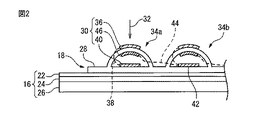
図2は、タッチパネル16及びタッチパネル16に貼付された押しボタン状シート18の概略構成を示す側断面図である。タッチパネル16は、例えば、表面型又は投影型の静電容量式タッチパネルであり、保護カバー22、透明電極膜又は電極パターン層24、及びガラス基板26を積層した構造を有し、操作者の指先等が接触又は近接した際の静電容量の変化をセンサ等で測定することで、タッチパネル16上のどの位置に指先等が接触又は近接したか(すなわちタッチ位置)を検出することができる。なお本実施例におけるタッチパネル16としては、操作者がタッチパネル表面(導電性物質)を物理的に変形させる必要がある抵抗膜方式等は除かれる。
FIG. 2 is a side sectional view showing a schematic configuration of the
押しボタン状シート18は、軟性樹脂等の可撓性及び一定の粘着性を有する、好ましくは透明のシート部材28と、金属等の導電性材料からなる、後述するシングルタップ及びマルチタップを実現するための導電体(電極)30とを有する。シート部材28は、所定の押圧方向(ここではシート表面又はタッチパネル16の表面に略垂直な方向)32に屈曲可能な少なくとも1つの凸状の反応領域を有し、図1に示すように本実施例では、4つの中空の凸部34a−34dがそれぞれ第1−第4の反応領域として形成されている。
The push button-
中空凸部の少なくとも1つ(図示例では中空凸部34a)は、導電体30として、反応領域34aの凸状表面(より具体的には、凸状部の上面)に設けられた第1の電極(電極層)36と、押圧方向32について第1の電極36の下方(より具体的には、シート部材28の下面側)でかつ反応領域34a内に設けられるとともに、透明、又は肉眼で認識できない細さの極細配線38等によって第1の電極36に電気的に接続された第2の電極(電極層)40とを有する。よって操作者の指先等が第1の電極36に接触又は近接したときは、第2の電極40が電気的に反応する(より具体的には、第1の電極36及び第2の電極40を介してタッチパネル16の表面の静電気が操作者の指先等に流れる、又はタッチパネル16と第2の電極40との間の静電容量が変化する)ことでタッチパネル16の静電容量が変化し、反応領域34aの直下のタッチパネル16の部位に操作者が接触又は近接したときと同様の効果が得られる。なお実際には、第1の電極36の上面にさらに保護シート等が設けられる場合もあるが、該保護シートは図示を省略する。
At least one of the hollow convex portions (
また押しボタン状シート18は、押しボタン状シート18の、第1の反応領域34a以外の部分(ここでは第2の反応領域34bの内部)に設けられた第3の電極42を備え、反応領域34aの凸状表面(第1の電極36)が押圧方向32に押圧されているときは、第2の電極40及び第3の電極42が導通(互いに電気的に接続される)ように構成されている。より具体的には、第1の反応領域34a内に、第1の電極36と第2の電極40との間に設けられるとともに、極細配線44等によって第3の電極42に電気的に接続された第4の電極46をさらに設け、第4の電極46は、第1の反応領域34aが押圧方向32に押圧されて屈曲することによって、第2の電極40に当接可能に構成されている。よって第4の電極46が第2の電極40に当接しているときは、第3の電極42及び第4の電極46を介してタッチパネル16の表面の静電気が操作者の指先等に流れる(又はタッチパネル表面の静電容量が変化する)ので、反応領域34bの直下のタッチパネル16の部位に操作者が接触又は近接したときと同様の効果が得られる。
Further, the push button-
なお図2の例では、各反応領域(中空凸部)は半球(ドーム)状に形成され、第1−第4の電極はいずれも層状の導電体(電極層)として構成され、さらに第1の電極36及び第4の電極46は、それぞれ第1の反応領域34aの凸状部を構成するシート部材の外面(表面)及び内面(裏面)に形成されているが、電極構造はこれに限られない。例えば図3に示すように、各反応領域(図3では第1の反応領域34aのみ図示)を押圧方向32に屈曲可能な角柱又は円柱状に形成してもよいし、第4の電極46は反応領域34aの内部において、該電極の周縁をシート部材28に支持されるようにしてもよい。
In the example of FIG. 2, each reaction region (hollow convex portion) is formed in a hemispherical (dome) shape, and the first to fourth electrodes are all configured as a layered conductor (electrode layer), and further, the first The
図4a及び図4bはそれぞれ、操作者が第1の反応領域34aに対して接触(タッチ)及び押圧したときのタッチパネル16の検出結果の一例を説明する図である。図4aに示すように、操作者の指先48等が第1の反応領域34a(第1の電極36)に接触すると、第1の反応領域34aに対応する1つのタッチパネル部位のみがタッチ入力された状態になる。
4a and 4b are diagrams for explaining an example of the detection result of the
次に図4bに示すように、操作者の指先48等が、第1の反応領域(中空凸部)34aを押圧して屈曲させると、上述のように第2の反応領域34b内の第3の電極42も電気的に反応し、第1の反応領域34a及び第2の反応領域34bにそれぞれ対応する2つのタッチパネル部位がタッチ入力された状態になる。このように本実施形態では、同一の反応領域に対して接触した場合と押圧した場合とで、異なるタッチ入力結果を得ることができる。
Next, as shown in FIG. 4b, when the operator's
本開示では、操作者が第1の電極36に触れた(但し中空凸部34aを一定量以上押圧しない)ときのように、操作者が触れた反応領域に対応するタッチパネル部位のみが反応(入力検知)することを「シングルタップ」と称し、操作者が中空凸部34aを押圧方向32に押圧して一定量以上屈曲させたときのように、操作者が触れた反応領域だけでなく他の反応領域(ここでは第2の反応領域34b)に対応するタッチパネル部位も反応することを「マルチタップ」と称する。よってシングルタップは、操作者がいずれかの反応領域に触れただけで生じ得るが、マルチタップは操作者がいずれかの反応領域を押下しないと生じない。
In the present disclosure, only the touch panel portion corresponding to the reaction region touched by the operator reacts (input) as when the operator touches the first electrode 36 (however, the hollow
また本開示では、押しボタン状シートのタッチパネルに貼付される側を下部(下面)と称し、これと反対側を上部(上面)と称するものとする。 Further, in the present disclosure, the side of the push button-shaped sheet attached to the touch panel is referred to as a lower portion (lower surface), and the opposite side thereof is referred to as an upper portion (upper surface).
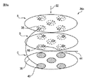
図5は、上述のマルチタップの応用例を説明する図であり、より具体的には、4つの反応領域34a−34dにおける電極の配置及び電気的接続関係(配線)を模式的に示す。ここでは、第1の電極36、第2の電極40及び第4の電極46をそれぞれ、A層、B層及びC層とも称し、反応領域34a−34dは同じ電極構造を有するものとする。
FIG. 5 is a diagram illustrating an application example of the above-mentioned multi-tap, and more specifically, schematically shows the arrangement of electrodes and the electrical connection relationship (wiring) in the four
図2を参照して説明したように、第1の反応領域34aのB層は第2の反応領域34bのC層に電気的に接続されているので、第1の反応領域34aが押圧されたときは、第1の反応領域34aのC層及び第2の反応領域34bのC層が導通し、図4bに示したようなマルチタップを実現することができる。同様に、第2の反応領域34bのB層は第3の反応領域34cのC層に電気的に接続されているので、第2の反応領域34bが押圧されたときは、第2の反応領域34bのC層及び第3の反応領域34cのC層が導通し、マルチタップを実現することができる。
As described with reference to FIG. 2, since the B layer of the
さらに、第3の反応領域34cのB層は第1の反応領域34aのC層40に電気的に接続されているので、第3の反応領域34cが押圧されたときは、第3の反応領域34cのC層及び第1の反応領域34aのC層が導通し、マルチタップを実現することができる。またさらに、第4の反応領域34dのB層は第2の反応領域34bのC層42に電気的に接続されているので、第4の反応領域34dが押圧されたときは、第4の反応領域34dのC層及び第2の反応領域34bのC層が導通し、マルチタップを実現することができる。
Further, since the B layer of the
図5の例では、ある反応領域に触れただけの場合はその触れた反応領域のみに対応するタッチパネル部位がタッチ位置として検出される(シングルタップ)が、ある反応領域を押圧して屈曲させたときは、押圧された反応領域を含む複数の反応領域に対応するタッチパネル部位がタッチ位置として検出される(マルチタップ)。なお図5の例では、1つの反応領域を押圧したときに2つの反応領域に関するマルチタップが行われるが、電極間の配線により、1つの反応領域を押圧したときに3つ以上の反応領域に関するマルチタップを実現することも可能である。 In the example of FIG. 5, when only a certain reaction area is touched, the touch panel portion corresponding only to the touched reaction area is detected as a touch position (single tap), but the certain reaction area is pressed and bent. When, the touch panel portion corresponding to a plurality of reaction areas including the pressed reaction area is detected as a touch position (multi-tap). In the example of FIG. 5, when one reaction region is pressed, multi-tap is performed for two reaction regions, but when one reaction region is pressed due to wiring between electrodes, three or more reaction regions are related. It is also possible to realize multi-tap.
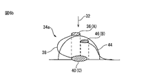
図6a及び図6bは、電極構造の好適な具体例を模式的に示す図であり、図6aはA−C層の斜視図、図6bは側面図である。上述のように、ある反応領域の第1の電極(A層)に触れただけの場合は、操作者はシングルタップを行うことを意図しているので、他の反応領域の電極に接続されている第4の電極(B層)が電気的に反応する(より具体的には、A層とB層が接触するか、タッチパネル表面の静電気がB層を経由してA層に流れるか、A層とB層との間の静電容量が変化する)ことは好ましくない。 6a and 6b are views schematically showing a suitable specific example of the electrode structure, FIG. 6a is a perspective view of the AC layer, and FIG. 6b is a side view. As described above, if the operator only touches the first electrode (layer A) of a reaction region, the operator intends to perform a single tap, so that the electrode is connected to an electrode of another reaction region. The fourth electrode (B layer) reacts electrically (more specifically, whether the A layer and the B layer come into contact with each other, or whether the static electricity on the touch panel surface flows to the A layer via the B layer, A. It is not preferable that the capacitance between the layer and the B layer changes).
そこで図6a及び図6bに示すように、第4の電極46は、押圧方向32について第1の電極36の後方投影領域内に存在しないように構成・配置される。このように第1の電極36及び第4の電極46の形状及び配置を決定することにより、第1の電極36(A層)が押圧方向32に変位しても第4の電極46(B層)に当接することが防止でき、また第1の電極36と第4の電極46との距離をできるだけ大きくして、操作者が第1の電極36に触れたときにB層(第4の電極)を通ってA層(第1の電極)に電流が流れる(つまり第2の反応領域34bがタッチされたと誤検出される)ことを防止することができる。
Therefore, as shown in FIGS. 6a and 6b, the
一方、第2の電極40は、その少なくとも一部が、押圧方向32について第4の電極46の後方投影領域(図示例では第1の電極36及び第4の電極46の双方の後方投影領域)内に存在するように構成・配置される。このように第2の電極40及び第4の電極46の形状及び配置を決定することにより、第1の反応領域34aを押圧したときにB層(第4の電極46)を確実にC層(第2の電極40)に接触させる(つまりマルチタップを実行する)ことができる。
On the other hand, at least a part of the
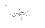
図7a及び図7bは、操作者が第1の電極(A層)に触れた際に、第4の電極(B層)及びこれに電気的に接続された他の電極が反応してしまうことを防止するための、反応領域の構造の他の具体例を示す。図7aの例では、第1の電極36及び第4の電極46がそれぞれ表面及び裏面に配置されているシート部材28の部分(凸状上部)50の厚み(押圧方向距離)を、図2の例より大きくして、操作者が第1の電極36に触れたときの誤検出を防止している。
7a and 7b show that when the operator touches the first electrode (layer A), the fourth electrode (layer B) and other electrodes electrically connected to the fourth electrode (layer B) react with each other. Another specific example of the structure of the reaction region for preventing the above is shown. In the example of FIG. 7a, the thickness (pressing direction distance) of the portion (convex upper portion) 50 of the
また図3に示したように、第4の電極46を凸状上部の裏面から離隔して、第1の電極36と第4の電極46との間に空気層52を設けることによっても、操作者が第1の電極36に触れたときの誤検出を防止することができる。
Further, as shown in FIG. 3, the operation can also be performed by separating the
さらに、図7bに示すように、第1の電極36と第4の電極46との間(図示例では第1の電極36とシート部材28(凸状表面)との間に)に、ポリイミド樹脂、フッ素樹脂系樹脂又はエポキシ樹脂等の、シート部材28を構成する材料よりも比誘電率が低い低誘電体材料等からなるスペーサ(図示例では層状体)54を配置することによっても、操作者が第1の電極36に触れたときの誤検出を防止することができる。一方、一般的なコンデンサに使用されるような高誘電体材料は、指先の接触(電荷の変化)を伝えてしまうことがあるので、好ましくない。このように、第1の電極36と第4の電極46との間に存在する物体の形状、寸法及び材質の少なくとも1つを、操作者が第1の電極36に触れることによって第4の電極46が電気的に反応しない(より具体的には、タッチパネル表面の静電気が第4の電極46を経由して第1の電極36から指先等に吸い取られない、又は第4の電極46と第1の電極36との間の静電容量が変化しない)ように選択・決定することにより、操作者が第1の電極36に触れただけでマルチタップが生じてしまうことを防止することができる。
Further, as shown in FIG. 7b, a polyimide resin is placed between the
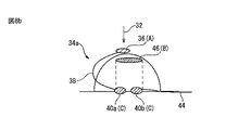
図8a及び図8bは、電極構造の好適な他の具体例を模式的に示す図であり、図8aはA−C層の斜視図、図8bは側面図である。本実施例では、第2の電極40(C層)は、極細配線38等によって第1の電極36(A層)に電気的に接続された第1の電極片40aと、極細配線44等によって他の反応領域の電極(例えば図2に示す第3の電極42)に電気的に接続された第2の電極片40bとを有し、第4の電極46(B層)は、反応領域34aが押圧方向32に押圧されて屈曲することによって、第1の電極片40aと第2の電極片40bとを電気的に接続するように構成されている。
8a and 8b are views schematically showing other suitable specific examples of the electrode structure, FIG. 8a is a perspective view of the AC layer, and FIG. 8b is a side view. In this embodiment, the second electrode 40 (C layer) is formed by the
より具体的には、第4の電極46は、その少なくとも一部が、押圧方向32について第1の電極片40a及び第2の電極片40bの双方の前方投影領域内に存在するように構成・配置される。このように第2の電極40及び第4の電極46の形状及び配置を決定することにより、第1の反応領域34aを押圧したときにB層(第4の電極46)が、第1の電極片40a及び第2の電極片40bの双方に当接して両電極片を互いに電気的に接続するので、マルチタップを実行することができる。また第4の電極46は他の電極に電気的に接続されていないので、操作者が第1の電極36に触れても、第4の電極46に関連する静電容量の変化(マルチタップ)は生じない。
More specifically, the
なお図6a又は図8aに示すように、押しボタン状シートの透明性を確保するために、1つの反応領域(ここでは第1の反応領域34a)の各層が複数(図示例では5つ)の電極(電極片)を有することが好ましい。
As shown in FIG. 6a or FIG. 8a, in order to ensure the transparency of the pushbutton-shaped sheet, each layer of one reaction region (here, the
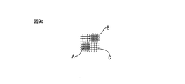
図9a−図9cは、電極形状の好適な具体例を、反応領域の押圧方向に沿って見た場合を示す。図6a(6b)に示した例では、A−C層に相当する電極は、それぞれ円形形状を有し、押圧方向32に(上方から)見た場合、図9aに示すように、C層の内部にA層及びB層が包含される構成となっている。 9a-9c show a suitable specific example of the electrode shape when viewed along the pressing direction of the reaction region. In the example shown in FIGS. 6a (6b), the electrodes corresponding to the layers AC and C each have a circular shape, and when viewed in the pressing direction 32 (from above), as shown in FIG. 9a, the electrodes of the layer C have a circular shape. The structure is such that the A layer and the B layer are included inside.
しかし電極構造はこれに限られず、例えば図9bに示すように、A−C層に相当する電極は、それぞれ棒状又は矩形形状を有し、押圧方向32に(上方から)見た場合、C層がA層及びB層にそれぞれ部分的に重複する構成としてもよい。 However, the electrode structure is not limited to this, and as shown in FIG. 9b, for example, the electrodes corresponding to the AC layer have a rod shape or a rectangular shape, respectively, and when viewed in the pressing direction 32 (from above), the C layer. May be configured to partially overlap the A layer and the B layer, respectively.
或いは、図9cに示すように、A−C層に相当する電極は、それぞれ極細細線からなるメッシュ形状を有し、押圧方向32に(上方から)見た場合、C層がA層及びB層にそれぞれ部分的に重複する構成としてもよい。このように各電極は、上述したシングルタップ及びマルチタップが実現できる限りにおいて、どのような形状・構造を具備してもよい。 Alternatively, as shown in FIG. 9c, the electrodes corresponding to the A-C layers each have a mesh shape composed of ultrafine wires, and when viewed in the pressing direction 32 (from above), the C layer is the A layer and the B layer. It may be configured so that each of them partially overlaps with each other. As described above, each electrode may have any shape and structure as long as the above-mentioned single tap and multi-tap can be realized.
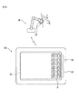
図10は、本開示に係る押しボタン状シートを備えたタッチパネルの応用例を説明する図である。ここでは、タッチパネル16を備えたタブレット等の携帯端末10を、無線通信等によって多関節ロボット56の教示を行うための教示操作盤として使用する。またロボット56は、互いに直交する3の駆動軸(X,Y,Z)について移動可能かつ回転可能に構成されたハンド等の可動部58を備えるものとする。
FIG. 10 is a diagram illustrating an application example of a touch panel provided with a push button-shaped sheet according to the present disclosure. Here, a
タッチパネル16は、ロボット56のX軸、Y軸及びZ軸のそれぞれについて、可動部58を並進移動させるための6つのタッチボタン(タッチスイッチ)60(X+、X−、Y+、Y−、Z+、Z−)と、可動部58を回転移動させるための6つのタッチボタン(タッチスイッチ)62(X+、X−、Y+、Y−、Z+、Z−の各々に弧線を付したもの)とを有する。タッチボタン60とタッチボタン62の各々は、上述のような反応領域(中空凸部)を12個備えた押しボタン状シート18をタッチパネル16上に貼付することによって、シングルタップ及びマルチタップを可能とする押しボタンとして機能する。
The
例えば、操作者がX+ボタンの位置を指先の感覚だけで探している間にX−ボタンに接触したときは、ロボット56の可動部58は移動しない。また例えば、操作者がX+ボタンを押圧したときは、可動部58はX軸の+方向にのみ並進移動可能な状態となる。このように、操作者が誤って反応領域を触れた場合の誤操作を防止することができる。また携帯端末10をブラウザやテキスト編集等の教示操作盤以外の目的で使用する場合でも、押しボタン状シート18をタッチパネル16に貼付したまま使用することができる。例えば、反応領域34a部に表示されたブラウザのリンクをシングルタップしたい場合、反応領域34aを押圧しないように接触(シングルタップ)すれば、押しボタン状シート18を貼付していない場合と同様の操作が可能である。つまりタブレットを教示操作盤として使用しない場合に、押しボタン状シートを剥がす手間を省くことができる。
For example, when the operator touches the X-button while searching for the position of the X + button only with the sensation of the fingertip, the
このように、本開示に係る押しボタン状シート18をタッチパネル16に使用することにより、同一のボタンに対して操作者が接触した場合と押圧した場合とで、異なる入力結果を得ることができ、従来よりも多様な入力が可能となる。また押しボタン状シート18(シート部材28)の材質を適宜選択することにより、タッチパネル16に対して着脱可能にすることもできるので、タッチパネル16が市販のものであっても、その用途に応じて使い勝手のよいタッチパネルを提供することができる。
As described above, by using the push button-shaped
10 携帯端末
12 本体
14 表示部
16 タッチパネル
18 押しボタン状シート
20 制御部
28 シート部材
30 導電体
34a−34d 反応領域
36 第1の電極
38、44 極細配線
40 第2の電極
40a 第1の電極片
40b 第2の電極片
42 第3の電極
46 第4の電極
50 凸状上部
52 空気層
54 スペーサ
56 ロボット
58 可動部
60、62 タッチボタン
10
Claims (7)
前記反応領域の凸状表面に設けられた第1の電極と、
前記押圧方向について前記第1の電極の下方でかつ前記反応領域内に設けられるとともに、前記第1の電極に電気的に接続された第2の電極と、
前記押しボタン状シートの、前記反応領域以外の部分に設けられた第3の電極と、を備え、
前記反応領域が前記押圧方向に屈曲しているときは、前記第2の電極及び前記第3の電極が導通するように構成されている、押しボタン状シート。 A pushbutton-shaped sheet having at least one convex reaction region that can be bent in a predetermined pressing direction.
A first electrode provided on the convex surface of the reaction region and
With respect to the pressing direction, a second electrode provided below the first electrode and in the reaction region and electrically connected to the first electrode,
A third electrode provided in a portion of the pushbutton-shaped sheet other than the reaction region is provided.
A push button-shaped sheet configured such that the second electrode and the third electrode are conductive when the reaction region is bent in the pressing direction.
前記第4の電極は、前記反応領域が前記押圧方向に屈曲することによって前記第2の電極に当接可能に構成されている、請求項1に記載の押しボタン状シート。 It further has a fourth electrode provided between the first electrode and the second electrode and electrically connected to the third electrode.
The push button-shaped sheet according to claim 1, wherein the fourth electrode is configured so that the reaction region can be brought into contact with the second electrode by bending in the pressing direction.
前記第2の電極は、前記第1の電極に電気的に接続された第1の電極片と、前記第1の電極に電気的に接続されずかつ前記第3の電極に電気的に接続された第2の電極片とを有し、
前記第4の電極は、前記反応領域が前記押圧方向に屈曲することによって前記第1の電極片と前記第2の電極片とを電気的に接続するように構成されている、請求項1に記載の押しボタン状シート。 It further has a fourth electrode provided between the first electrode and the second electrode.
The second electrode is the first electrode piece electrically connected to the first electrode and the third electrode which is not electrically connected to the first electrode and is electrically connected to the third electrode. It has a second electrode piece and
The fourth electrode is configured to electrically connect the first electrode piece and the second electrode piece by bending the reaction region in the pressing direction. The described push button sheet.
Priority Applications (4)
| Application Number | Priority Date | Filing Date | Title |
|---|---|---|---|
| JP2018245612A JP6867366B2 (en) | 2018-12-27 | 2018-12-27 | Push button sheet and touch panel |
| DE102019135543.5A DE102019135543A1 (en) | 2018-12-27 | 2019-12-20 | Push button plate and touch panel |
| CN201911326184.XA CN111381735B (en) | 2018-12-27 | 2019-12-20 | Button-like sheet and touch panel |
| US16/727,120 US10976927B2 (en) | 2018-12-27 | 2019-12-26 | Push button sheet and touch panel |
Applications Claiming Priority (1)
| Application Number | Priority Date | Filing Date | Title |
|---|---|---|---|
| JP2018245612A JP6867366B2 (en) | 2018-12-27 | 2018-12-27 | Push button sheet and touch panel |
Publications (2)
| Publication Number | Publication Date |
|---|---|
| JP2020107099A JP2020107099A (en) | 2020-07-09 |
| JP6867366B2 true JP6867366B2 (en) | 2021-04-28 |
Family
ID=71122901
Family Applications (1)
| Application Number | Title | Priority Date | Filing Date |
|---|---|---|---|
| JP2018245612A Active JP6867366B2 (en) | 2018-12-27 | 2018-12-27 | Push button sheet and touch panel |
Country Status (4)
| Country | Link |
|---|---|
| US (1) | US10976927B2 (en) |
| JP (1) | JP6867366B2 (en) |
| CN (1) | CN111381735B (en) |
| DE (1) | DE102019135543A1 (en) |
Families Citing this family (1)
| Publication number | Priority date | Publication date | Assignee | Title |
|---|---|---|---|---|
| JPWO2021070660A1 (en) * | 2019-10-10 | 2021-04-15 |
Family Cites Families (12)
| Publication number | Priority date | Publication date | Assignee | Title |
|---|---|---|---|---|
| JPH0917278A (en) | 1995-06-29 | 1997-01-17 | Idec Izumi Corp | Push button sheet of display operation panel |
| JP4090939B2 (en) * | 2002-05-29 | 2008-05-28 | ニッタ株式会社 | Capacitive sensor and manufacturing method thereof |
| KR100960942B1 (en) * | 2009-03-24 | 2010-06-03 | 주식회사 포인칩스 | Complex-type input device with touch sensing features |
| JP5466916B2 (en) * | 2009-10-15 | 2014-04-09 | 日本メクトロン株式会社 | Switch module |
| JP5347913B2 (en) * | 2009-11-06 | 2013-11-20 | ソニー株式会社 | SENSOR DEVICE, ELECTRONIC DEVICE, AND METHOD FOR MANUFACTURING SENSOR DEVICE |
| JP2012195254A (en) | 2011-03-18 | 2012-10-11 | Shin Etsu Polymer Co Ltd | Operating member |
| JP5137150B1 (en) * | 2012-02-23 | 2013-02-06 | 株式会社ワコム | Handwritten information input device and portable electronic device provided with handwritten information input device |
| JP6032371B2 (en) * | 2013-09-20 | 2016-11-30 | 株式会社村田製作所 | Detection sensor and input device |
| US10804897B2 (en) * | 2014-01-10 | 2020-10-13 | Touchplus Information Corp. | Touch-sensitive keypad control device |
| WO2015174126A1 (en) * | 2014-05-16 | 2015-11-19 | 富士フイルム株式会社 | Conductive sheet for touchscreen and capacitive touchscreen |
| CN107210158B (en) * | 2015-02-04 | 2019-08-23 | 松下知识产权经营株式会社 | Input unit and the electronic equipment that the input unit is utilized |
| JP2017021471A (en) | 2015-07-08 | 2017-01-26 | 株式会社デンソーウェーブ | Electronic device |
-
2018
- 2018-12-27 JP JP2018245612A patent/JP6867366B2/en active Active
-
2019
- 2019-12-20 CN CN201911326184.XA patent/CN111381735B/en active Active
- 2019-12-20 DE DE102019135543.5A patent/DE102019135543A1/en active Pending
- 2019-12-26 US US16/727,120 patent/US10976927B2/en active Active
Also Published As
| Publication number | Publication date |
|---|---|
| DE102019135543A1 (en) | 2020-07-16 |
| CN111381735B (en) | 2024-03-29 |
| CN111381735A (en) | 2020-07-07 |
| US10976927B2 (en) | 2021-04-13 |
| US20200210062A1 (en) | 2020-07-02 |
| JP2020107099A (en) | 2020-07-09 |
Similar Documents
| Publication | Publication Date | Title |
|---|---|---|
| JP5493739B2 (en) | Sensor device and information processing device | |
| US11068084B2 (en) | Input device | |
| US8508492B2 (en) | Touch panel and method of detecting press operation position thereon | |
| EP2210162B1 (en) | Input device | |
| JP5347913B2 (en) | SENSOR DEVICE, ELECTRONIC DEVICE, AND METHOD FOR MANUFACTURING SENSOR DEVICE | |
| US8912930B2 (en) | Capacitive touch keyboard | |
| KR20170049591A (en) | Device and method for force and proximity sensing employing an intermediate shield electrode layer | |
| TW200822682A (en) | Multi-function key with scrolling | |
| TWI423105B (en) | Conductor pattern structure of capacitive touch panel | |
| JP2012018478A (en) | External keypad | |
| JP4799655B2 (en) | Small equipment | |
| US10289210B1 (en) | Enabling touch on a tactile keyboard | |
| US10804897B2 (en) | Touch-sensitive keypad control device | |
| JP2018106616A (en) | Input apparatus | |
| EP2650764A2 (en) | Conductor pattern structure of capacitive touch panel | |
| US20200073492A1 (en) | Touch apparatus | |
| JP6199541B2 (en) | Touch input device | |
| JP6867366B2 (en) | Push button sheet and touch panel | |
| US11474653B2 (en) | Buttonless device | |
| JP6600584B2 (en) | Capacitive input device | |
| JP6677416B2 (en) | Case for operation panel and display device | |
| JP6913554B2 (en) | Touch panel, touch input device | |
| JP2015153004A (en) | Input device, and detection method thereof | |
| JP5898720B2 (en) | Input processing device | |
| JP2014075022A (en) | Input device |
Legal Events
| Date | Code | Title | Description |
|---|---|---|---|
| A621 | Written request for application examination |
Free format text: JAPANESE INTERMEDIATE CODE: A621 Effective date: 20200513 |
|
| A977 | Report on retrieval |
Free format text: JAPANESE INTERMEDIATE CODE: A971007 Effective date: 20210226 |
|
| TRDD | Decision of grant or rejection written | ||
| A01 | Written decision to grant a patent or to grant a registration (utility model) |
Free format text: JAPANESE INTERMEDIATE CODE: A01 Effective date: 20210309 |
|
| A61 | First payment of annual fees (during grant procedure) |
Free format text: JAPANESE INTERMEDIATE CODE: A61 Effective date: 20210408 |
|
| R150 | Certificate of patent or registration of utility model |
Ref document number: 6867366 Country of ref document: JP Free format text: JAPANESE INTERMEDIATE CODE: R150 |