JP6867104B2 - Floating graphical user interface - Google Patents
Floating graphical user interface Download PDFInfo
- Publication number
- JP6867104B2 JP6867104B2 JP2016008456A JP2016008456A JP6867104B2 JP 6867104 B2 JP6867104 B2 JP 6867104B2 JP 2016008456 A JP2016008456 A JP 2016008456A JP 2016008456 A JP2016008456 A JP 2016008456A JP 6867104 B2 JP6867104 B2 JP 6867104B2
- Authority
- JP
- Japan
- Prior art keywords
- field
- view
- virtual object
- widget
- virtual
- Prior art date
- Legal status (The legal status is an assumption and is not a legal conclusion. Google has not performed a legal analysis and makes no representation as to the accuracy of the status listed.)
- Active
Links
- 230000033001 locomotion Effects 0.000 claims description 111
- 238000000034 method Methods 0.000 claims description 46
- 230000000007 visual effect Effects 0.000 claims description 35
- 238000001514 detection method Methods 0.000 claims description 7
- 230000008569 process Effects 0.000 description 17
- 210000003128 head Anatomy 0.000 description 11
- 238000010586 diagram Methods 0.000 description 8
- 230000008859 change Effects 0.000 description 6
- 230000006870 function Effects 0.000 description 6
- 210000005252 bulbus oculi Anatomy 0.000 description 4
- 230000001133 acceleration Effects 0.000 description 3
- 230000005540 biological transmission Effects 0.000 description 2
- 230000000694 effects Effects 0.000 description 2
- 230000005484 gravity Effects 0.000 description 2
- 230000001052 transient effect Effects 0.000 description 2
- 241000238631 Hexapoda Species 0.000 description 1
- 230000009471 action Effects 0.000 description 1
- 230000003190 augmentative effect Effects 0.000 description 1
- 238000005452 bending Methods 0.000 description 1
- 230000000903 blocking effect Effects 0.000 description 1
- 238000004590 computer program Methods 0.000 description 1
- 210000001508 eye Anatomy 0.000 description 1
- 210000000887 face Anatomy 0.000 description 1
- 230000003287 optical effect Effects 0.000 description 1
- 230000004044 response Effects 0.000 description 1
- 238000010079 rubber tapping Methods 0.000 description 1
- 230000036962 time dependent Effects 0.000 description 1
Images


Landscapes
- User Interface Of Digital Computer (AREA)
Description
本発明は、仮想現実空間(VR)、拡張現実空間(AR)などの仮想空間において、操作者が操作を行うための適切なグラフィカルユーザインターフェースの表示を行う装置、方法、コンピュータプログラム、および、コンピュータプログラムを記録した記録媒体に関するものであって、特に、ユーザの頭部に装着したヘッドマウント・ディスプレイ(HMD)を用いた没入型仮想空間で用いることに適しているものである。 The present invention presents a device, method, computer program, and computer that displays an appropriate graphical user interface for an operator to operate in a virtual space such as virtual reality space (VR) or augmented reality space (AR). It relates to a recording medium on which a program is recorded, and is particularly suitable for use in an immersive virtual space using a head-mounted display (HMD) worn on the user's head.
ユーザの頭部に装着され、眼前に配置されたディスプレイ等によってユーザに仮想空間における画像を提示可能なヘッドマウント・ディスプレイ(HMD)が知られている。特許文献1には、視野の周辺に相当する部分に複数のアイコン、メニュー等のウィジェットを透視図法を用いて表示することによって、中央部の視野を確保しつつ、多数のアイコン、メニュー等のウィジェットも表示することが記載されている。 There is known a head-mounted display (HMD) that is attached to the user's head and can present an image in a virtual space to the user by a display or the like placed in front of the eyes. In Patent Document 1, a plurality of widgets such as icons and menus are displayed in a portion corresponding to the periphery of the visual field by using a perspective projection method, so that a visual field in the central portion is secured and a large number of widgets such as icons and menus are displayed. Is also stated to be displayed.
特許文献1に記載される手法は、仮想空間における実質的な視野が視野中央部のみとなってしまう。本発明は、なるべく視野をさえぎらないようにウィジェットを仮想空間上に表示することを課題とする。 In the method described in Patent Document 1, the actual field of view in the virtual space is limited to the central part of the field of view. An object of the present invention is to display a widget on a virtual space so as not to block the field of view as much as possible.
本発明によれば、仮想空間中に置かれているウィジェットを用いて入力を行う入力方法であって、前記仮想空間中で注視点を移動させる注視点移動ステップと、前記ウィジェットと前記注視点を重なっているか否かを判断し、重なっている場合には前記ウィジェットを選択するウィジェット選択ステップと、前記選択されたウィジェットに対応する入力を行う入力ステップを有する、入力方法が得られる。 According to the present invention, it is an input method in which input is performed using a widget placed in a virtual space, in which a gaze point moving step for moving the gaze point in the virtual space, and the widget and the gaze point are displayed. An input method having a widget selection step of determining whether or not they overlap and selecting the widget if they overlap, and an input step of inputting corresponding to the selected widget can be obtained.
また、本発明によれば、仮想空間中に置かれているウィジェットを用いて入力を行う入力装置であって、前記仮想空間中で注視点を移動させる注視点移動部と、前記ウィジェットと前記注視点を重なっているか否かを判断し、重なっている場合には前記ウィジェットを選択するウィジェット選択部と、前記選択されたウィジェットに対応する入力を行う入力部を有する、入力装置が得られる。 Further, according to the present invention, an input device for inputting using a widget placed in a virtual space, the gaze point moving unit for moving the gaze point in the virtual space, the widget, and the note. An input device having a widget selection unit that determines whether or not the viewpoints overlap and, if they overlap, selects the widget and an input unit that performs input corresponding to the selected widget can be obtained.
本発明によれば、仮想空間における実質的な視野を広くし得る。
本発明のその他の特徴及び利点は、後述する実施例の説明、添付の図面、及び請求の範囲から明らかなものとなる。
According to the present invention, a substantial field of view in a virtual space can be widened.
Other features and advantages of the present invention will become apparent from the description of Examples described below, the accompanying drawings, and the claims.
[本発明の実施形態の説明]
最初に、本発明の実施形態の内容を列記して説明する。本発明の一実施形態のプログラムは、以下のような構成を備える。
[Explanation of Embodiments of the Present Invention]
First, the contents of the embodiments of the present invention will be listed and described. The program of one embodiment of the present invention has the following configuration.
(項目1)
仮想空間中に置かれているウィジェットを用いて入力を行う入力方法であって、前記仮想空間中で注視点を移動させる注視点移動ステップと、前記ウィジェットと前記注視点を重なっているか否かを判断し、重なっている場合には前記ウィジェットを選択するウィジェット選択ステップと、前記選択されたウィジェットに対応する入力を行う入力ステップを有する、入力方法。
(Item 1)
It is an input method in which input is performed using a widget placed in the virtual space, and it is determined whether or not the gaze point moving step for moving the gaze point in the virtual space overlaps with the widget. An input method having a widget selection step of determining and selecting the widget when overlapping, and an input step of inputting corresponding to the selected widget.
本項目の入力方法によれば、仮想空間における実質的な視野を広くし得る。例えば、本項目の入力方法、フローティング・グラフィカルユーザインターフェース、すなわち、仮想空間上に浮遊しているように表示されている小型化したウィジェットを用いることにより視野を確保することができるとともに、仮想空間上の視線の移動という常に行われている操作を用いて入力を行うことができるので、入力を行うために特別な操作を行う必要がない。特に、ヘッドマウント・ディスプレイ(HMD)本体の姿勢データを用い仮想空間上の視線の移動を行っている場合には、その効果は顕著である。 According to the input method of this item, the practical field of view in the virtual space can be widened. For example, the field of view can be secured by using the input method of this item, the floating graphical user interface, that is, the miniaturized widget displayed as floating in the virtual space, and on the virtual space. Since the input can be performed using the constantly performed operation of moving the line of sight of, there is no need to perform a special operation for inputting. In particular, the effect is remarkable when the line of sight is moved in the virtual space using the posture data of the head-mounted display (HMD) main body.
(項目2)
前記注視点移動ステップが、前記仮想空間に対する視野を移動させることによって、前記注視点を移動させる視野移動ステップの一部であることを特徴とする、項目1に記載の入力方法。
(Item 2)
The input method according to item 1, wherein the gazing point moving step is a part of a visual field moving step for moving the gazing point by moving the visual field with respect to the virtual space.
(項目3)
前記視野移動ステップが、計測した操作者の頭部の動きを用いて前記仮想空間に対する視野を移動させることを特徴とする、項目2に記載の入力方法。
(Item 3)
The input method according to item 2, wherein the field of view moving step moves the field of view with respect to the virtual space by using the measured movement of the operator's head.
(項目4)
前記ウィジェットを前記視野の中の初期状態の位置(X fv0 ,Y fv0 )に対応する仮想空間の位置(X vs0 ,Y vs0 ,Z vs0 )に置き、前記ウィジェットの仮想空間中の移動速度ベクトルVを0に初期化する初期化ステップと、前記ウィジェットを仮想空間中で前記移動速度ベクトルVで移動させるウィジェット移動ステップと、前記ウィジェットの前記視野の中の位置が、前記視野の中の初期状態の位置と一致した場合、前記移動速度ベクトルVを0と再初期化するウィジェット移動速度再初期化ステップと、前記ウィジェットが視野の外に位置するようになったことを判定するウィジェット視野外判定ステップと、前記ウィジェット視野外判定ステップが、前記ウィジェットが視野の外に位置すると判定したとき、前記ウィジェットを前記移動させた視野の中で前記視野の中の初期状態の位置に戻るような値を前記移動速度ベクトルVに与えるウィジェット移動速度設定ステップを更に有することを特徴とする、項目2又は3に記載の入力方法。
(Item 4)
The widget is placed at a position (X vs0, Y vs0, Z vs0) in the virtual space corresponding to the position (X fv0, Y fv0) in the initial state in the field of view, and the moving speed vector V in the virtual space of the widget is placed. The initialization step of initializing to 0, the widget moving step of moving the widget with the moving speed vector V in the virtual space, and the position of the widget in the field of view are the initial states in the field of view. When the position matches, the widget movement speed reinitialization step of reinitializing the movement speed vector V to 0, and the widget out-of-sight determination step of determining that the widget is located outside the field of view. When the widget out-of-sight determination step determines that the widget is located outside the field of view, the moving value is such that the widget returns to the initial state position in the field of view in the moved field of view. The input method according to item 2 or 3, further comprising a widget moving speed setting step given to the speed vector V.
(項目5)
前記ウィジェット移動速度再初期化ステップが、前記ウィジェットの前記視野の中の位置が、前記視野の中の初期状態の位置と一致したと判定するのは、前記ウィジェットの前記視野の中の左右方向(X方向)の前記視野の中の位置が、前記視野の中の初期状態の位置X fv0 と一致したときであり、前記ウィジェット視野外判定ステップにおいて、前記ウィジェットが視野の外に位置するようになったときとは、前記視野の中で左右方向(X方向)の外に位置するようになったときであり、前記ウィジェット移動速度設定ステップにおいて、前記ウィジェットを前記移動させた視野の中で前記視野の中の初期状態の位置に戻るような値を前記移動速度ベクトルVに与えるとは、前記視野の中の左右方向(X方向)のみについて、前記視野の中の初期状態の位置Xfv0に戻るように仮想空間中で移動させるような値を前記移動速度ベクトルVに与えることであること、を特徴とする項目4に記載の入力方法。
(Item 5)
The widget movement speed reinitialization step determines that the position of the widget in the field of view coincides with the position of the initial state in the field of view in the left-right direction in the field of view of the widget. When the position in the field of view (in the X direction) coincides with the position X fv0 in the initial state in the field of view, the widget is located outside the field of view in the widget out-of-field determination step. The time is when the position is located outside the left-right direction (X direction) in the field of view, and in the step of setting the moving speed of the widget, the field of view in which the widget is moved is the field of view. Giving the moving speed vector V a value that returns to the initial state position in the field means that the moving speed vector V returns to the initial state position Xfv0 in the field only in the left-right direction (X direction) in the field. The input method according to item 4, wherein a value to be moved in the virtual space is given to the moving speed vector V.
(項目6)
前記入力ステップが、一定時間以上継続して前記ウィジェットが注視されていることを判定した時に、前記選択されたウィジェットに対応する入力を行うことを特徴とする、項目1〜5のいずれか一項に記載の入力方法。
(Item 6)
Any one of items 1 to 5, wherein when the input step determines that the widget is being watched continuously for a certain period of time or longer, the input corresponding to the selected widget is performed. Input method described in.
(項目7)
項目1〜6のいずれか一項に記載の方法を実行するためのプログラム。
(項目8)
項目1〜6のいずれか一項に記載の方法を実行するためのプログラムを記録した記録媒体。
(Item 7)
A program for executing the method according to any one of items 1 to 6.
(Item 8)
A recording medium on which a program for executing the method according to any one of items 1 to 6 is recorded.
(項目9)
仮想空間中に置かれているウィジェットを用いて入力を行う入力装置であって、前記仮想空間中で注視点を移動させる注視点移動部と、前記ウィジェットと前記注視点を重なっているか否かを判断し、重なっている場合には前記ウィジェットを選択するウィジェット選択部と、前記選択されたウィジェットに対応する入力を行う入力部を有する、入力装置。
(Item 9)
It is an input device that inputs using a widget placed in the virtual space, and whether or not the gaze point moving unit that moves the gaze point in the virtual space overlaps the widget and the gaze point. An input device having a widget selection unit that determines and selects the widget when overlapping, and an input unit that performs input corresponding to the selected widget.
本項目の入力装置によれば、仮想空間における実質的な視野を広くし得る。例えば、本項目の入力装置、フローティング・グラフィカルユーザインターフェース、すなわち、仮想空間上に浮遊しているように表示されている小型化したウィジェットを用いることにより視野を確保することができるとともに、仮想空間上の視線の移動という常に行われている操作を用いて入力を行うことができるので、入力を行うために特別な操作を行う必要がない。特に、ヘッドマウント・ディスプレイ(HMD)本体の姿勢データを用い仮想空間上の視線の移動を行っている場合には、その効果は顕著である。 According to the input device of this item, the practical field of view in the virtual space can be widened. For example, the field of view can be secured by using the input device of this item, the floating graphical user interface, that is, the miniaturized widget displayed as floating in the virtual space, and in the virtual space. Since the input can be performed using the constantly performed operation of moving the line of sight of, there is no need to perform a special operation for inputting. In particular, the effect is remarkable when the line of sight is moved in the virtual space using the posture data of the head-mounted display (HMD) main body.
(項目10)
前記注視点移動部が、前記仮想空間に対する視野を移動させることによって、前記注視点を移動させる視野移動部の一部であることを特徴とする、項目9に記載の入力装置。
(Item 10)
Item 9. The input device according to item 9, wherein the gazing point moving unit is a part of a visual field moving unit that moves the gazing point by moving the visual field with respect to the virtual space.
(項目11)
前記視野移動部が、計測した操作者の頭部の動きを用いて前記仮想空間に対する視野を移動させることを特徴とする、項目10に記載の入力装置。
(Item 11)
The input device according to item 10, wherein the field of view moving unit moves the field of view with respect to the virtual space by using the measured movement of the operator's head.
(項目12)
前記ウィジェットを前記視野の中の初期状態の位置(X fv0 ,Y fv0 )に対応する仮想空間の位置(X vs0 ,Y vs0 ,Z vs0 )に置き、前記ウィジェットの仮想空間中の移動速度ベクトルVを0に初期化する初期化部と、前記ウィジェットを仮想空間中で前記移動速度ベクトルVで移動させるウィジェット移動部と、前記ウィジェットの前記視野の中の位置が、前記視野の中の初期状態の位置と一致した場合、前記移動速度ベクトルVを0と再初期化するウィジェット移動速度再初期化部と、前記ウィジェットが視野の外に位置するようになったことを判定するウィジェット視野外判定部と、前記ウィジェット視野外判定部が、前記ウィジェットが視野の外に位置すると判定したとき、前記ウィジェットを前記移動させた視野の中で前記視野の中の初期状態の位置に戻るような値を前記移動速度ベクトルVに与えるウィジェット移動速度設定部を更に有することを特徴とする、項目10又は11に記載の入力装置。
(Item 12)
The widget is placed at a position (X vs0, Y vs0, Z vs0) in the virtual space corresponding to the position (X fv0, Y fv0) in the initial state in the field of view, and the moving speed vector V in the virtual space of the widget is placed. The initialization unit that initializes to 0, the widget moving unit that moves the widget with the moving speed vector V in the virtual space, and the position of the widget in the field of view are in the initial state in the field of view. A widget movement speed reinitialization unit that reinitializes the movement speed vector V to 0 when the position matches, and a widget out-of-field determination unit that determines that the widget is located outside the field of view. When the widget out-of-sight determination unit determines that the widget is located outside the field of view, the moving value is such that the widget returns to the initial state position in the field of view in the moved field of view. The input device according to item 10 or 11, further comprising a widget moving speed setting unit given to the speed vector V.
(項目13)
前記ウィジェット移動速度再初期化部が、前記ウィジェットの前記視野の中の位置が、前記視野の中の初期状態の位置と一致したと判定するのは、前記ウィジェットの前記視
野の中の左右方向(X方向)の前記視野の中の位置が、前記視野の中の初期状態の位置Xfv0 と一致したときであり、前記ウィジェット視野外判定部において、前記ウィジェットが視野の外に位置するようになったときとは、前記視野の中で左右方向(X方向)の外に位置するようになったときであり、前記ウィジェット移動速度設定部において、前記ウィジェットを前記移動させた視野の中で前記視野の中の初期状態の位置に戻るような値を前記移動速度ベクトルVに与えるとは、前記視野の中の左右方向(X方向)のみについて、前記視野の中の初期状態の位置Xfv0に戻るように仮想空間中で移動させるような値を前記移動速度ベクトルVに与えることであること、を特徴とする項目12に記載の入力装置。
(Item 13)
The widget movement speed reinitialization unit determines that the position of the widget in the field of view coincides with the position of the initial state in the field of view in the left-right direction in the field of view of the widget. When the position in the field of view (in the X direction) coincides with the position Xfv0 in the initial state in the field of view, the widget is located outside the field of view in the widget out-of-field determination unit. The time is when the position is located outside the left-right direction (X direction) in the field of view, and in the widget movement speed setting unit, the widget is moved in the field of view of the field of view. Giving the moving speed vector V a value that returns to the position in the initial state of the inside means that the moving speed vector V returns to the position Xfv0 in the initial state in the field of view only in the left-right direction (X direction). The input device according to item 12, wherein a value to be moved in the virtual space is given to the moving speed vector V.
(項目14)
前記入力部が、一定時間以上継続して前記ウィジェットが注視されていることを判定した時に、前記選択されたウィジェットに対応する入力を行うことを特徴とする、項目9〜13のいずれか一項に記載の入力装置。
(Item 14)
Any one of items 9 to 13, characterized in that, when the input unit determines that the widget is being watched continuously for a certain period of time or longer, the input corresponding to the selected widget is performed. The input device described in.
[本発明の実施形態の詳細]
以下、図面を参照して、本発明の実施の形態を説明する。なお、この実施の形態は、各種センサ(例えば、加速度センサや角速度センサ)を備え、その姿勢データを計測できるヘッドマウント・ディスプレイ(HMD)を用い、その姿勢データを用いてヘッドマウント・ディスプレイ(HMD)に表示される画像をスクロールし仮想空間上の視線の移動を実現する没入型仮想空間を前提として記述されているが、通常のディスプレイ上に仮想空間を表示し、キーボード、マウスやジョイスティックなどによる入力によって、仮想空間上の視線を移動するものに適用することもできる。
[Details of Embodiments of the present invention]
Hereinafter, embodiments of the present invention will be described with reference to the drawings. In this embodiment, a head-mounted display (HMD) provided with various sensors (for example, an acceleration sensor or an angular velocity sensor) and capable of measuring the posture data thereof is used, and the head-mounted display (HMD) using the posture data is used. ) Is described on the premise of an immersive virtual space that scrolls the image displayed in the virtual space and realizes the movement of the line of sight on the virtual space. It can also be applied to moving the line of sight in the virtual space by input.
また、図中、同一の構成要素には同一の符号を付してある。
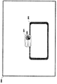
図1は、本発明によって浮遊しているように表示される小型化したウィジェットの一例を示す図であり、図2は、図1に表示されている要素を説明するとともに、ウィジェット201とカーソル202の位置の初期状態の一例について示す図である。
Further, in the figure, the same components are designated by the same reference numerals.
FIG. 1 is a diagram showing an example of a miniaturized widget displayed as floating according to the present invention, and FIG. 2 shows an element displayed in FIG. 1 and a
ウィジェット201は、仮想空間上で浮遊しているように表示されている。
図1において、ウィジェット201は、無人機(ドローン)がボタンを吊り下げている形態をしているが、これは、対象となる仮想空間で浮遊していて違和感をおこさない種類のデザインを選べばよく、UFO、ロボット、昆虫、鳥、妖精やおばけなどでもよい。
The
In FIG. 1, the
図1では、ウィジェット201は、操作対象となる2つのボタンを有しているが、操作対象となるボタンなどを2つ設けることに限ることはなく、画面の大きさや精細度、ウィジェット201でさえぎられる視野の大きさ、必要な操作の種類などにあわせ、適切なものを適切な数設ければよい。さらには、操作対象となるボタンなどを常に表示する必要もなく、通常のグラフィカルユーザインターフェースのドロップダウンリスト、ポップアップメニューやコンテキストメニューと同様に、ウィジェット201がいったん選択されたことを感知して、操作対象となるボタンなどを展開して表示するものでもよい。
In FIG. 1, the
カーソル202は、仮想空間上で注視している場所、すなわち、注視点を示すものである。
姿勢データを計測できるヘッドマウント・ディスプレイ(HMD)を用いた場合であっても、その姿勢データはヘッドマウント・ディスプレイ(HMD)を装着した操作者の頭部の動きを検出するものが多く、その場合、その姿勢データによって仮想空間中の視野が移動するように制御し、注視点自体は視野の中央、すなわち、画面の中央に固定されている場合が通常である。この場合は、このカーソル202の表示は省略しても、操作上の違和感はない。
The
Even when a head-mounted display (HMD) capable of measuring posture data is used, the posture data often detects the movement of the head of the operator wearing the head-mounted display (HMD). In this case, the posture data controls the movement of the visual field in the virtual space, and the gazing point itself is usually fixed at the center of the visual field, that is, the center of the screen. In this case, even if the display of the
なお、この注視点はウィジェット201への操作を行うための注視点なので、必ずしも視野の中央、すなわち、画面の中央に置く必要はなく、視野の中央からは偏移した位置に置くことも可能である。その場合には、カーソル202が表示されているほうが操作は容易となる。また、眼球の移動を検知したり、なんらかの補助的な入力を用いたりすることによって、視野の移動とは独立して注視点を移動させることができる場合にも、カーソル202が表示されているほうが操作は容易となる。
Since this gazing point is for operating the
また、カーソル202を表示する場合においても、カーソル202が視野をさえぎることを考えれば、ウィジェット201とカーソル202が示す注視点が近接した時のみ、カーソル202が表示されるようにしてもよい。
Further, even when the
窓203は、仮想空間上の固定された位置に存在する窓であって、仮想空間と視野204の相対的な位置関係を示すために便宜的に記載されたものである。また、図2に示すように、視野204の左右方向をX方向、上下方向をY方向、奥行き方向をZ方向と呼ぶこととする。
The
以下、図2〜9を用いて、ウィジェット201の仮想空間上での動きを説明する。この説明は、注視点は、視野の中央に固定され、カーソル202も画面の中央に固定されつつ表示されていることを前提としてなされているが、注視点が視野の中央からは偏移した位置に置かれている場合、視野を固定しつつ注視点を移動させることができる場合、カーソル202の表示が省略されたりウィジェット202と近接した場合のみに表示されたりする場合にも適用することができる。したがって、カーソル202が表示されない場合には、カーソル202の代わりに注視点と解釈すればよい。
Hereinafter, the movement of the
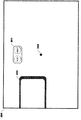
既に述べたように、図2は、ウィジェット201とカーソル202の位置の初期状態の一例について示す図である。
図2に示す一例では、ウィジェット201は、初期状態として、左右方向(X方向)は視野のほぼ中央に位置するが、上下方向(Y方向)は視野の中央より上側に位置している。この初期状態の位置を視野に対する座標軸で(X fv0 ,Y fv0 )とし、仮想空間中の位置を仮想空間中の座標軸で(X vs0 ,Y vs0 ,Z vs0 )とする。
As already described, FIG. 2 is a diagram showing an example of the initial state of the positions of the
In the example shown in FIG. 2, in the initial state, the
ウィジェット201を初期状態で表示する視野の中での位置は、これに限られるものではない。ウィジェット201で視野の重要な部分がさえぎられることを回避することのみを考えれば、ウィジェット201が視野の中央から離れて表示されるほうがよく、ウィジェット201が視野の隅に表示されるものでもなんら問題はない。しかしながら、次に示すように、視野を移動させてウィジェット201を視野の中央であるカーソル202の位置に移動させ、互いに重ね合わせることによって、ウィジェット201に対して操作を行うので、ウィジェット201が視野の中央から離れた位置にあればあるほど、操作に必要な時間がかかることとなる。
The position in the field of view for displaying the
図3は、図2の状態から、視野を上にΔY(+Y方向)、および、若干右側にΔX(+X方向)に移動させたときの図である。ウィジェット201は、基本的には仮想空間に対して固定した位置で浮遊しており、図3では、仮想空間中の座標軸で(X vs0 ,Y vs0 ,Zvs0 )に留まっているが、視野を上(+Y方向)、若干右側(+X方向)に移動させることにより、ウィジェット201は視野に対する座標軸で(X fv0 −ΔX,Y fv0 −ΔY)に移動し、結局、視野の中央、若干左よりに持ってくることができる。窓203は仮想空間中で移動しないから、図2と図3を比較すれば、ウィジェット201と窓203の位置関係が変化していないことがみてとれる。
FIG. 3 is a view when the field of view is moved upward by ΔY (+ Y direction) and slightly to the right in ΔX (+ X direction) from the state of FIG.
図3に示されたものは、この時点で実際には、カーソル202がウィジェット201の右側のボタンに重なっており、ウィジェット201の右側のボタンは選択されたことを表示するために変化した表示となっている。ウィジェット201の右側のボタンに対応した操作を行うためには、この選択を確定させることが必要となる。この例でいえば、視野を固定し、カーソル202を、ウィジェット201の右側のボタンに一定時間以上重ねて表示させることによって、選択を確定させるのが自然な操作手法ではあるが、それ以外に、キーボード等による補助的な入力を用いたり、ウィジェット201上に選択の確定のためのボタンを設けたり、色々な手法を用いることができる。
What is shown in FIG. 3 is that at this point the
なお、図3では、カーソル202がウィジェット201の右側のボタンに重なったことによって、単純に、ウィジェット201の右側のボタンを選択することとしているが、既に述べたように、通常のグラフィカルユーザインターフェースのドロップダウンリスト、ポップアップメニューやコンテキストメニューと同様に、ウィジェット201がいったん選択されたことを感知して、操作対象となるボタンなどを展開して表示するものでもよい。
In FIG. 3, since the
更に、以下に説明するように、ウィジェット201が仮想空間中で移動することを考えると、ウィジェット201が選択されたかを判断するためには、ウィジェット201とカーソル202が重なっていることを条件として判断するのみならず、ウィジェット201の仮想空間中での移動速度が0である条件を加えてもよい。
Further, as described below, considering that the
次に、図4〜7を用いて、視野を左右方向(X方向)に移動させたときに、ウィジェット201がどのように表示されるかについて説明する。
図4は、図2の状態から、視野を右(+X方向)に移動させた状態で、その結果、ウィジェット201は視野の中で左(−X方向)に移動している。既に述べたように、ウィジェット201は、基本的には仮想空間に対して固定した位置で浮遊しているので、図2と図4を比較すれば、ウィジェット201と窓203の相対的な位置関係が変化していないことがみてとれる。
Next, how the
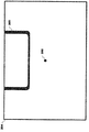
FIG. 4 shows a state in which the field of view is moved to the right (+ X direction) from the state of FIG. 2, and as a result, the
図5は、図4から更に視野を右(+X方向)に移動させた状態である。この時点では、ウィジェット201は更に左(−X方向)に移動し、その一部が視野の外に位置することとなる。この時点までは、ウィジェット201は仮想空間に対して固定した位置で浮遊しているが、ウィジェット201は左右方向(X方向)に視野の外に位置した時点で、視野の中での初期状態の位置に戻ろうと仮想空間中で移動を開始する。なお、ウィジェット201が視野の外に位置したことを判断する条件は、ウィジェット201の一部が視野の外に位置した場合、ウィジェット201の半分が視野の外に位置した場合、ウィジェット201が完全に視野の外に位置した場合などのいずれでもよい。
FIG. 5 shows a state in which the field of view is further moved to the right (+ X direction) from FIG. At this point, the
この時点で戻る視野の中での初期状態の位置は、具体的には、視野の中での左右方向(X方向)の初期状態の位置X fv0 であって、この時点で視野の中での上下方向(Y方向)にも初期状態の位置と相違している場合であっても、上下方向(Y方向)の相違を維持したままに、視野の中での左右方向(X方向)の初期状態の位置X fv0 に戻るように仮想空間中で移動するほうがよい。 The position of the initial state in the field of view returning at this point is specifically the position of the initial state X fv0 in the left-right direction (X direction) in the field of view, and is in the field of view at this point. Even if the position is different from the initial position in the vertical direction (Y direction), the initial position in the horizontal direction (X direction) in the visual field is maintained while maintaining the difference in the vertical direction (Y direction). It is better to move in the virtual space to return to the state position X fv0.
ウィジェット201が仮想空間中で実際に浮遊しているようにみせるために、この視野の中での初期状態の位置に戻ろうとする仮想空間中での移動は有限の速度Vxで行われ、視野の移動が遅い場合と速い場合で見ための追従の状況を変化させるのが望ましいが、瞬時移動であってもよい。
In order to make the
図6は、視野の中での初期状態の位置、すなわち、この場合では左右方向(X方向)で視野の初期状態の位置X fv0 に戻ったウィジェット201を示す図である。仮想空間中でウィジェット201は移動したので、この時点では、仮想空間中の座標軸で初期状態の位置である(X vs0 ,Y vs0 ,Z vs0 )とは異なる場所に位置している。図2におけるウィジェット201と窓203の位置関係と、図6におけるウィジェット201と窓203の位置関係を比較すると、図6の時点ではウィジェット201と仮想空間の位置関係が変化していることがみてとれる。
FIG. 6 is a diagram showing a
続いて、図7〜10を用いて、視野を上下(Y方向)に移動させたときに、ウィジェット201がどのように表示されるかについて説明する。
図7は、図2の状態から、視野を下(−Y方向)に移動させた状態で、その結果、ウィジェット201は視野の中で上(+Y方向)に移動している。図4と同様に、図2と図7を比較すれば、ウィジェット201と窓203の相対的な位置関係が変化していないことがみてとれる。
Subsequently, with reference to FIGS. 7 to 10, how the
FIG. 7 shows a state in which the visual field is moved downward (−Y direction) from the state of FIG. 2, and as a result, the
図8は、図7から更に視野を下(−Y方向)に移動させた状態である。この時点では、ウィジェット201は、その一部が視野の外に位置することとなる。図5のようにウィジェット201が左右方向(X方向)で視野の外に位置する場合には、ウィジェット201は視野の中での初期状態の位置に戻ろうと仮想空間中で移動を開始するが、この実施例では、上下方向(Y方向)の場合はそのような移動はおこなわない。
FIG. 8 shows a state in which the field of view is further moved downward (-Y direction) from FIG. 7. At this point, a part of the
図9は、図8から更に視野を下(−Y方向)に移動させた結果、ウィジェット201が完全に視野の外に位置し、見えなくなっていることを示す図である。
図4〜7に記載される視野を左右方向(X方向)に移動させた場合と、図7〜10に記載される視野を上下方向(Y方向)に移動させた場合で、ウィジェット201が視野の外側に位置した場合の処理を異ならせたのは以下の理由による。
FIG. 9 is a diagram showing that the
The
人間の視野が左右方向(X方向)に移動する動作、すなわち、図14におけるY軸を中心として回転するヨー角の動きは、首を左右にねじる動作の他に、体全体が左右を向く動作があり、体全体を左右に向けたりすることによって人間の視野が左右方向(X方向)に移動したあと、新たに向いた方向を中心として更に左右を向くという動作をすることができる。これに対し、視野が上下方向(Y方向)に移動する動作、すなわち、図14におけるX軸を中心として回転するピッチ角の動きは、首を前後に曲げる動作しかなく、新たに向いた位置を長い間継続するとか、新たに向いた位置を中心として更に上下方向(Y方向)に視野を移動させることは難しく、動き自体が一時的に留まるものである。すなわち、視野を上下方向(Y方向)に移動させる場合と、視野を左右方向(X方向)に移動させる場合で、人間の動作が異なることから、視野を上下方向(Y方向)に移動させる場合と、視野を左右方向(X方向)に移動させる場合で、ウィジェット201の動きを異ならせる方が自然なものとなるからである。
The movement of the human visual field to move in the left-right direction (X direction), that is, the movement of the yaw angle rotating around the Y-axis in FIG. 14, is a movement in which the entire body faces left and right in addition to the movement of twisting the neck left and right. By turning the whole body to the left or right, the human field of view moves in the left-right direction (X direction), and then the movement of turning to the left or right centering on the newly turned direction can be performed. On the other hand, the movement of the field of view in the vertical direction (Y direction), that is, the movement of the pitch angle rotating around the X axis in FIG. It is difficult to continue for a long time or to move the field of view further in the vertical direction (Y direction) around the newly oriented position, and the movement itself temporarily stops. That is, when the visual field is moved in the vertical direction (Y direction) and when the visual field is moved in the horizontal direction (X direction), the human movement is different. This is because it is more natural to make the movement of the
したがって、例えば、表示の対象となる仮想空間が無重力空間であって、図14におけるX軸を中心として回転するピッチ角の動きとして、体全体が前転や後転するような動きを許容するのであれば、図7〜10の記載にも関わらず、視野を上下方向(Y方向)に移動させウィジェット201が視野の外側に位置した場合にも、図4〜7に記載される視野を左右方向(X方向)に移動させた場合と同様にウィジェット201を視野の中での初期状態の位置に戻すように構成したほうが自然なものとなる。
Therefore, for example, the virtual space to be displayed is a zero gravity space, and the movement of the pitch angle rotating around the X axis in FIG. 14 allows the whole body to roll forward or backward. If there is, the field of view shown in FIGS. 4 to 7 is moved in the left-right direction even when the field of view is moved in the vertical direction (Y direction) and the
仮想空間中の視野の移動としては、これら、左右方向(X方向)、上下方向(Y方向)に加え、視線の方向、すなわち、図14でいう奥行き方向(Z方向)を中心として回転す
るロール角の動きがある。
As for the movement of the visual field in the virtual space, in addition to these horizontal directions (X direction) and vertical direction (Y direction), a roll that rotates around the direction of the line of sight, that is, the depth direction (Z direction) in FIG. There is a movement of the horns.
この奥行き方向(Z方向)を中心として回転するロール角の動きは、実際には左右に首を傾ける動作であって、その動きは、首を前後に曲げる動作によって、視野を上下方向(Y方向)に移動させる、ピッチ角の動きの場合と同様の制限があり、動き自体が一時的なものに留まるので、上下方向(Y方向)に視野が移動するときと同様に、Z軸を中心として回転するロール角の動きを行った結果ウィジェット201が視野の外に位置したとしても、ウィジェット201を仮想空間中で移動させる必要はない。
The movement of the roll angle that rotates around the depth direction (Z direction) is actually the movement of tilting the neck to the left and right, and the movement is the movement of bending the neck back and forth to move the field of view up and down (Y direction). ) Has the same restrictions as the movement of the pitch angle, and the movement itself is temporary, so the center of the Z-axis is the same as when the field of view moves in the vertical direction (Y direction). Even if the
これに対し、上下方向(Y方向)に視野が移動するときに議論したように、表示の対象となる仮想空間が無重力空間であって、奥行き方向(Z方向)を中心として回転するロール角の動きとして、体全体が左右に側転する動きを許容する場合には、仮想空間中での操作者とウィジェット201のZ軸を中心として回転する方向の位置が相対的に保持されるように、ウィジェット201が操作者の動きに追従して仮想空間中で動くようにすればよい。このようにウィジェット201を仮想空間中で移動させることも、結局、ウィジェット201を視野の中で固定して表示するということなので、過渡的な場合を除けば、その移動によってウィジェット201が視野の外に出ることはなく、その点について判断し特別な処理をする必要はない。
On the other hand, as discussed when the field of view moves in the vertical direction (Y direction), the virtual space to be displayed is a zero gravity space, and the roll angle that rotates around the depth direction (Z direction). When allowing the entire body to roll sideways as a movement, the position in the direction of rotation about the Z axis of the operator and the
ここまでは理解を容易とするために、視野の動きが、図14でいうヨー角、ピッチ角、ロール角の動きによるものとして説明してきたが、実際には操作者もウィジェット201も仮想空間中に存在するので、操作者が仮想空間中を動き回る場合についても考える必要がある。
Up to this point, for ease of understanding, the movement of the visual field has been described as being due to the movement of the yaw angle, pitch angle, and roll angle shown in FIG. 14, but in reality, both the operator and the
まず、操作者が仮想空間中を動き回る場合のうち、図2,14でいうZ軸方向に動くことを考える。
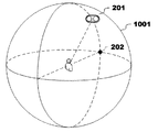
ウィジェット201が操作の対象となるものであることを考えると、ウィジェット201の見かけの大きさが変わらないほうが望ましい。それを実現するためには、仮想空間中での操作者とウィジェット201の間の距離が保持されるように、図10に示すように、ウィジェット201は、仮想空間中で操作者を中心とした仮想球体1001の上に存在させる必要がある。
First, consider that the operator moves around in the virtual space in the Z-axis direction as shown in FIGS. 2 and 14.
Considering that the
以下、説明を簡単にするために、ウィジェット201、カーソル202、操作者の位置関係は、図10に示す位置関係であるとする。このときには、操作者からは図2のような視野となっている。
Hereinafter, for the sake of simplicity, the positional relationship between the
そして、仮想空間上で操作者が、操作者とカーソル202を結ぶZ軸方向に移動した場合には、この仮想球体1001も操作者とカーソル202を結ぶZ軸方向に移動するので、ウィジェット201も仮想球体1001上に存在することを維持するために、結局、操作者のZ軸方向への移動に追従して移動するのが好ましい。この場合も、ウィジェット201が仮想空間中で実際に浮遊しているようにみせるために移動は有限の速度で行われ、操作者の移動が遅い場合と速い場合で見ための追従の状況を変化させるのが望ましいが、瞬時移動であってもよい。
Then, when the operator moves in the Z-axis direction connecting the operator and the
なお、ウィジェット201が細かい移動を繰り返すことは、見た目上煩わしいので、この追従は、操作者のZ軸方向への移動がある一定以上の大きさになってから行ってもよく、追従していない操作者の移動が残っている場合には、その後、ウィジェット201の移動が必要となった時にまとめておこなえばよい。
Since it is visually annoying for the
このようにウィジェット201を仮想空間中で移動させることとは、結局、ウィジェット201を視野の中で固定して表示するということなので、Z軸方向でウィジェット201に近づく方向の視野の移動があまりにも速くウィジェット201の仮想空間中での移動が追いつかず、過渡的に視野の外に出る場合を除けば、その移動によってウィジェット201が視野の外に出ることはない。そして、この過渡的な場合であっても、視野の移動が停止すればウィジェット201は視野の中に戻ってくるので、ウィジェット201が視野の内外のいずれに存在するかについて判断し特別な処理を行う必要はない。
Moving the
次に、操作者が図2,14でいうX軸方向、Y軸方向に移動することを考える。その場合、図10に示すような、操作者を中心とした仮想球体1001上にウィジェット201を存在させることを前提とすると、操作者自体が左右方向(X方向)、上下方向(Y方向)に移動した場合にも、仮想球体1001自体が移動し、その結果ウィジェット201が仮想球体1001上から逸脱することとなる。
Next, consider that the operator moves in the X-axis direction and the Y-axis direction as shown in FIGS. 2 and 14. In that case, assuming that the
視野が左右方向(X方向)に移動した結果、ウィジェット201が視野の外に移動した場合には、ウィジェット201が視野の中での初期状態の位置に戻ろうとする動きをすることは既に説明した。操作者自体がX軸方向、Y軸方向に移動した結果、視野が左右方向(X方向)、上下方向(Y方向)に移動する場合には、この既に説明したウィジェット201の動きに加え、ウィジェット201と移動した操作者の新たな位置を結ぶ直線を求め、その直線と移動後の仮想球体1001が交わる仮想空間中の位置にウィジェット201を移動させる必要がある。
It has already been explained that when the
この場合も、ウィジェット201が仮想空間中で実際に浮遊しているようにみせるために移動は有限の速度で行われ、操作者の移動が遅い場合と速い場合で見ための追従の状況を変化させるのが望ましいが、瞬時移動であってもよい。
In this case as well, the movement is performed at a finite speed in order to make the
なお、この場合も、操作者のZ軸方向への移動と同様に、ウィジェット201が細かい移動を繰り返すことは、見た目上煩わしいので、この追従は、操作者の移動がある一定以上の大きさになってから行ってもよく、追従していない操作者の移動が残っている場合には、その後、ウィジェット201の移動が必要となった時にまとめておこなえばよい。
In this case as well, it is visually annoying that the
図11,12は、ここまで説明したウィジェット201の動作を実現する処理を示すフローチャートである。なお、このフローチャートは基本的な処理のみ示すものであって、たとえば、Z軸方向の移動についての処理や、仮想球体1001上からのウィジェット201の逸脱を防ぐ処理は省略している。
11 and 12 are flowcharts showing the processes for realizing the operation of the
図11は、視野204の移動、および、ウィジェット201の移動についての処理を示している。
ステップS1101とステップS1102は、ウィジェット201の表示についての初期化ステップで、ウィジェット201を視野の中の初期状態の位置(X fv0 ,Y fv0 )に対応する仮想空間の位置(X vs0 ,Y vs0 ,Z vs0 )に置き、視野全体を描画するとともに、仮想空間上のウィジェット201の移動速度ベクトルVを0と初期化する。
FIG. 11 shows a process for moving the field of
Steps S1101 and S1102 are initialization steps for displaying the
ステップS1103はウィジェット201を仮想空間中で移動速度ベクトルVで移動させるウィジェット移動ステップである。この実施例では、初期状態を含むほとんどの状態で移動速度ベクトルV=0であるから、そのときは、このステップS1103はなんら動作をしない。しかしながら、移動速度ベクトルVに0以外の値が設定された時には、その値を用いて、後に述べるステップS1107、ステップS1108によって、ウィジェット201を視野の中での初期状態の位置に戻すように、VΔtだけ、仮想空間中で移動させる。
Step S1103 is a widget moving step of moving the
ステップS1104とステップS1105は、ウィジェット201が視野の中での初期状態の位置に戻ったことを検知し、移動速度ベクトルVを0と再初期化するウィジェット移動速度再初期化ステップである。
Step S1104 and step S1105 are widget movement speed reinitialization steps of detecting that the
ステップS1106は、操作者の操作に応じて視野を仮想空間内で移動させ、それに対応して視野の描画をする視野移動ステップである。なお、この視野移動ステップは、仮想空間中の視野が移動するように制御することによって、注視点を移動させるものであるが、眼球の移動を検知したり、なんらかの補助的な入力を用いたりすることによって、視野の移動とは独立して注視点を移動させることができる場合には、この視野移動ステップの中で併せてその処理をすればよい。視野移動に基づくものであれ、眼球の移動に基づくものであれ、この視野移動ステップの中の注視点移動に関する部分は、注視点移動ステップともいうことができる。 Step S1106 is a field of view moving step in which the field of view is moved in the virtual space according to the operation of the operator and the field of view is drawn correspondingly. In this visual field movement step, the gazing point is moved by controlling the visual field in the virtual space to move, but the movement of the eyeball is detected or some auxiliary input is used. As a result, if the gazing point can be moved independently of the movement of the visual field, the processing may be performed together in this visual field movement step. Regardless of whether it is based on the movement of the visual field or the movement of the eyeball, the part related to the movement of the gazing point in this moving step of the visual field can also be referred to as the moving gazing step.
この視野移動ステップは、ヘッドマウント・ディスプレイ(HMD)が計測した操作者の頭部の動きを検出し、検出した姿勢データによって、仮想空間中の視野が移動するように制御するように構成することが望ましい。 This field of view movement step is configured to detect the movement of the operator's head measured by the head mounted display (HMD) and control the field of view in the virtual space to move based on the detected posture data. Is desirable.
ステップS1107は、ウィジェット201が移動中であるかどうかを判定するステップである。ウィジェット201が移動中である場合には、移動中に視野が移動し、視野の中での初期状態の位置に対応する仮想空間中の位置が変動していることに対応するために、新たな移動速度ベクトルVを設定する必要があるので、ステップS1109に遷移する。
Step S1107 is a step of determining whether or not the
ステップS1108は、ウィジェット201の視野上の左右方向(X方向)の位置が視野の外に出ているかを判断するウィジェット視野外判定ステップである。既に述べたように、ウィジェット201が視野の外に位置したことを判断する条件は、ウィジェット201の一部が視野の外に位置した場合、ウィジェット201の半分が視野の外に位置した場合、ウィジェット201が完全に視野の外に位置した場合などのいずれでもよい。
Step S1108 is a widget out-of-field determination step for determining whether the position of the
ステップS1109は、ウィジェット201を視野の中での初期状態の位置に戻すために、移動速度ベクトルVに値を設定するウィジェット移動速度設定ステップである。既に述べたように、この移動速度ベクトルVを用いて、ステップS1103において、ウィジェット201を視野の中での初期状態の位置に戻すように、仮想空間中で移動させる。そのために、移動速度ベクトルVの方向は、ウィジェット201の現在の仮想空間中の位置から、現在の視野の中での初期状態の位置に対応する仮想空間中の位置を結ぶ方向である。そして、ウィジェット201が仮想空間中で実際に浮遊しているようにみせるために、この移動速度ベクトルVに設定される値は、ベクトルの大きさがある一定の有限の値を超えないように定められるのがよい。
Step S1109 is a widget movement speed setting step of setting a value in the movement speed vector V in order to return the
このステップS1109までが、視野204の移動、および、ウィジェット201の移動についての処理である。
次に、図12を用いて、ウィジェット201が選択されるときの処理を説明する。
Up to step S1109 is a process for moving the field of
Next, the process when the
ステップS1201では、ウィジェット201とカーソル202が重なっているかを判断している。このカーソル202は注視点にあるので、結局、ウィジェット201が注視点の位置にあるか否かを判断していることとなる。
In step S1201, it is determined whether the
ステップS1201で、ウィジェット201とカーソル202が重なっていると判断されたときは、ステップS1202でウィジェット201を選択状態の表示に変化させる。この選択状態の表示としては、ハイライト、色の変更、別の態様の表示への変化など各種考えられる。また、この時点で、通常のグラフィカルユーザインターフェースのドロップダウンリスト、ポップアップメニューやコンテキストメニューと同様に、操作対象となるボタンなどを展開して表示するものでもよい。
When it is determined in step S1201 that the
これらステップS1201、ステップS1202でウィジェット選択ステップを構成している。
ステップS1203では、ウィジェット201が一定時間以上選択状態となっているかを判断し、一定時間以上選択状態となっている場合には、ステップS1205で選択されたウィジェット201に対応した操作を実行する入力ステップである。まだ、一定時間以上選択されていない場合には、そのままステップS1103まで戻る。
These steps S1201 and S1202 constitute a widget selection step.
In step S1203, it is determined whether the
ステップS1204は、ステップS1201でウィジェット201とカーソル202が重なっていないと判断されたとき、および、ステップS1205にてウィジェット201に対応した操作を実行したときに、ウィジェット201を非選択状態の表示とするもので、その後、ステップS1103まで戻る。
In step S1204, when it is determined in step S1201 that the
次に、図13〜16を用いて、ウィジェット201を表示するためのシステムについて説明する。なお、既に述べたように、これら図13〜15は、各種センサ(例えば、加速度センサや角速度センサ)を備え、その姿勢データを計測できるヘッドマウント・ディスプレイ(HMD)を用いを前提として記述されているが、通常のディスプレイ上に仮想空間を表示し、キーボード、マウスやジョイスティックなどによる入力によって、仮想空間上の視線を移動するものに適用することもできる。
Next, a system for displaying the
図13は、ウィジェット201を表示するためのシステム1300の概要を示す図である。
図13に示すように、システム1300は、ヘッドマウント・ディスプレイ(HMD)1310、制御回路部1320、ポジション・トラッキング・カメラ(位置センサ)1330、並びに外部コントローラ1340を備える。
FIG. 13 is a diagram showing an outline of the
As shown in FIG. 13, the
ヘッドマウント・ディスプレイ(HMD)1310は、ディスプレイ1312およびセンサ1314を具備する。ディスプレイ1312は、ユーザの視野を完全に覆うよう構成された非透過型の表示装置であり、ユーザはディスプレイ1312に表示される画面のみを観察することができる。そして、非透過型のヘッドマウント・ディスプレイ(HMD)1310を装着したユーザは、外界の視野を全て失うため、制御回路部1320において実行されるアプリケーションにより表示される仮想空間に完全に没入する表示態様となる。
The head-mounted display (HMD) 1310 includes a
ヘッドマウント・ディスプレイ(HMD)1310が具備するセンサ1314は、ディスプレイ1312近辺に固定される。センサ1314は、地磁気センサ、加速度センサ、および/または傾き(角速度、ジャイロ)センサを含み、これらの1つ以上を通じて、ユーザの頭部に装着されたヘッドマウント・ディスプレイ(HMD)1310(ディスプレイ1312)の各種動きを検知することができる。特に角速度センサの場合には、図14のように、ヘッドマウント・ディスプレイ(HMD)1310の動きに応じて、ヘッドマウント・ディスプレイ(HMD)1310の3軸回りの角速度を経時的に検知し、各軸回りの角度(傾き)の時間変化を決定することができる。
The
図14を参照して傾きセンサで検知可能な角度情報データについて説明する。図示のように、ヘッドマウント・ディスプレイ(HMD)を装着したユーザの頭部を中心として、XYZ座標が規定される。ユーザが直立する垂直方向をY軸、Y軸と直交しディスプレイ1312の中心とユーザを結ぶ方向をZ軸、Y軸およびZ軸と直交する方向の軸をX軸とする。傾きセンサでは、各軸回りの角度(即ち、Y軸を軸とした回転を示すヨー角、X軸を軸とした回転を示すピッチ角、Z軸を軸とした回転を示すロール角で決定される傾き)を検知し、その経時的な変化により、動き検知部1610が視野情報として角度(傾き)情報データを決定する。
The angle information data that can be detected by the tilt sensor will be described with reference to FIG. As shown, the XYZ coordinates are defined centering on the head of the user wearing the head-mounted display (HMD). The vertical direction in which the user stands upright is defined as the Y axis, the direction orthogonal to the Y axis and the center of the
図13に戻り、システム1300が備える制御回路部1320は、ヘッドマウント・ディスプレイ(HMD)を装着したユーザを3次元仮想空間に没入させ、3次元仮想空間に基づく動作を実施させるための制御回路部1320として機能する。図13のように、制御回路部1320は、ヘッドマウント・ディスプレイ(HMD)1310とは別のハードウェアとして構成してもよい。当該ハードウェアは、パーソナルコンピュータやネットワークを通じたサーバ・コンピュータのようなコンピュータとすることができる。即ち、互いにバス接続されたCPU、主記憶、補助記憶、送受信部、表示部、および入力部を備える任意のコンピュータとすることができる。
Returning to FIG. 13, the
代替として、制御回路部1320は、オブジェクト操作装置として、ヘッドマウント・ディスプレイ(HMD)1310内部に搭載されてもよい。ここでは、制御回路部1320は、オブジェクト操作装置の全部または一部の機能のみを実装することができる。一部のみを実装した場合には、残りの機能をヘッドマウント・ディスプレイ(HMD)1310側、またはネットワークを通じたサーバ・コンピュータ(図示せず)側に実装してもよい。
Alternatively, the
システム1300が備えるポジション・トラッキング・カメラ(位置センサ)1330は、制御回路部1320に通信可能に接続され、ヘッドマウント・ディスプレイ(HMD)1310の位置追跡機能を有する。ポジション・トラッキング・カメラ(位置センサ)1330は、赤外線センサや複数の光学カメラを用いて実現される。ポジション・トラッキング・カメラ(位置センサ)1330を具備し、ユーザ頭部のヘッドマウント・ディスプレイ(HMD)の位置を検知することによって、システム1300は、3次元仮想空間における仮想カメラ/没入ユーザの仮想空間位置を正確に対応付け、特定することができる。
The position tracking camera (position sensor) 1330 included in the
より具体的には、ポジション・トラッキング・カメラ(位置センサ)1330は、図15に例示的に示すように、ヘッドマウント・ディスプレイ(HMD)1310上に仮想的に設けられ、赤外線を検知する複数の検知点の実空間位置をユーザの動きに対応して経時的に検知する。そして、ポジション・トラッキング・カメラ(位置センサ)1330により検知された実空間位置の経時的変化に基づいて、ヘッドマウント・ディスプレイ(HMD)1310の動きに応じた各軸回りの角度の時間変化を決定することができる。 More specifically, the position tracking camera (position sensor) 1330 is virtually provided on the head-mounted display (HMD) 1310 as exemplified in FIG. 15, and a plurality of positions for detecting infrared rays are detected. The real space position of the detection point is detected over time in response to the movement of the user. Then, based on the time-dependent change of the real space position detected by the position tracking camera (position sensor) 1330, the time change of the angle around each axis according to the movement of the head-mounted display (HMD) 1310 is determined. can do.
再度、図13に戻り、システム1300は外部コントローラ1340を備える。外部コントローラ1340は、一般的なユーザ端末であり、図示のようなスマートフォンとすることができるが、これに限定されない。例えば、PDA、タブレット型コンピュータ、ゲーム用コンソール、ノートPCのようなタッチ・ディスプレイを備える携帯型デバイス端末であれば如何なるデバイスにもすることができる。即ち、外部コントローラ1340は、互いにバス接続されたCPU、主記憶、補助記憶、送受信部、表示部、および入力部を備える任意の携帯型デバイス端末とすることができる。ユーザは、外部コントローラ1340のタッチ・ディスプレイに対し、タップ、スワイプおよびホールドを含む各種タッチ動作を実施可能である。
Returning to FIG. 13, the
図16のブロック図は、本発明の実施の形態による、3次元仮想空間内のオブジェクト操作を実装するために、制御回路部1320を中心にコンポーネントの主要機能の構成を示したものである。制御回路部1320では、主に、センサ1314/ポジション・トラッキング・カメラ(位置センサ)1330および外部コントローラ1340からの入力を受け、該入力を処理してディスプレイ1312への出力を行う。制御回路部1320は、主に、動き検知部1610、注視点移動部1621および視野画像生成部1630、並びにウィジェット制御部1640を含み、各種情報を処理する。
The block diagram of FIG. 16 shows the configuration of the main functions of the components centering on the
動き検知部1610では、センサ1314/ポジション・トラッキング・カメラ(位置センサ)1330からの動き情報の入力に基づいて、ユーザの頭部に装着されたヘッドマウント・ディスプレイ(HMD)1310の動きデータを測定する。本発明では、特に、傾きセンサ1314により経時的に検知される角度情報、およびポジション・トラッキング・カメラ(位置センサ)1330により経時的に検知される位置情報を決定する。
The
視野移動部1620は、空間情報格納部1650に格納された3次元仮想空間情報、並びに傾きセンサ1314に検知される角度情報、および位置センサ130に検知される位置情報に基づく仮想カメラの視野方向の検知情報に基づいて視野情報を求める。視野移動部1620に含まれる注視点移動部1621は、その視野情報に基づいて、3次元仮想空間における注視点情報を決定する。なお、眼球の移動を検知したり、なんらかの補助的な入力を用いたりすることによって、視野の移動とは独立して注視点を移動させることができる場合には、この注視点移動部1621は、それも併せて処理することとなる。
The field of
また、視野移動部1620において、ヘッドマウント・ディスプレイ(HMD)が、センサ1314/ポジション・トラッキング・カメラ(位置センサ)1330によって計測した操作者の頭部の動きを用い、仮想空間中の視野が移動するように制御するように構成することが望ましい。
Further, in the field of
視野画像生成部1630は、その視野情報と、ウィジェット制御部1640から送られてくるウィジェット201の位置に基づいて視野画像を生成する。
ウィジェット制御部1640は、図11,12で示した制御の大半をつかさどる部分である。具体的には、ウィジェット制御部1640は、ウィジェット選択部1641、入力部1642、ウィジェット移動部1643、ウィジェット移動速度再初期化部1644、ウィジェット視野外判定部1645、ウィジェット速度設定部1646を有している。ウィジェット選択部1641はウィジェット201とカーソル202が重なっているかを判断し、ウィジェット201とカーソル202が重なっていると判断されたときは、ウィジェット201を選択状態の表示に変化させる処理を行い、入力部1642はウィジェット201が一定時間以上選択状態となっているかを判断し、一定時間以上選択状態となっている場合には、選択されているウィジェット201に対応した操作を実行する。なお、ウィジェット選択部1641、入力部1642は、外部コントローラ1340からの入力を受け、それに基づいてウィジェット201が選択されたか否かを判断してもよい。ウィジェット移動部1643はウィジェット201を仮想空間上の移動速度ベクトルVで移動させる処理を行い、ウィジェット移動速度再初期化部1644はウィジェット201が視野の中での初期状態の位置に戻ったことを検知し、移動速度ベクトルVを0と再初期化する処理を行い、ウィジェット視野外判定部1645は、ウィジェット201の視野上の左右方向(X方向)の位置が視野の外に出ているかを判断する処理を行い、ウィジェット速度設定部1646はウィジェット201を視野の中での初期状態の位置に戻すために、移動速度ベクトルVに値を設定する処理を行う。
The field of view
The
初期化部1660は初期化についての処理を担う。
なお、図16において、様々な処理を行う機能ブロックとして記載される各要素は、ハードウェア的には、CPU、メモリ、その他の集積回路で構成することができ、ソフトウェア的には、メモリにロードされた各種プログラムなどによって実現される。したがって、これらの機能ブロックがハードウェア、ソフトウェア、又はそれらの組み合わせによって実現できることが当業者に理解される。
The initialization unit 1660 is in charge of processing for initialization.
In FIG. 16, each element described as a functional block that performs various processes can be configured by a CPU, a memory, and other integrated circuits in terms of hardware, and is loaded into the memory in terms of software. It is realized by various programs that have been made. Therefore, it will be understood by those skilled in the art that these functional blocks can be realized by hardware, software, or a combination thereof.
以上、本発明の実施の形態について説明したが、本発明は上記実施形態に限定されるものではない。前述の請求項に記載されるこの発明の精神及び範囲から逸脱することなく、様々な実施形態の変更がなされ得ることを当業者は理解するであろう。 Although the embodiments of the present invention have been described above, the present invention is not limited to the above embodiments. Those skilled in the art will appreciate that various embodiments can be modified without departing from the spirit and scope of the invention described in the preceding claims.
201 ウィジェット
202 カーソル
203 窓
204 視野
1001 仮想球体
1300 システム
1310 ヘッドマウント・ディスプレイ(HMD)
1312 ディスプレイ
1314 センサ
1320 制御回路部
1330 ポジション・トラッキング・カメラ(位置センサ)
1340 外部コントローラ
1610 動き検知部
1620 視野移動部
1621 注視点移動部
1630 視野画像生成部
1640 ウィジェット制御部
1641 ウィジェット選択部
1642 入力部
1643 ウィジェット移動部
1644 ウィジェット移動速度再初期化部
1645 ウィジェット視野外判定部
1646 ウィジェット速度設定部
1650 空間情報格納部
1660 初期化部
201
1312
1340
Claims (8)
前記仮想空間は、第1仮想オブジェクトと第2仮想オブジェクトとを含み、
前記仮想空間中で、前記第1仮想オブジェクトと前記第2仮想オブジェクトとを含む視野を定義するステップと、
ヘッドマウント・ディスプレイの動きを検出する検出ステップと、
検出された前記動きに基づいて前記仮想空間中で前記視野を移動させる視野移動ステップと、
前記視野の移動に基づいて、前記仮想空間中で前記第1仮想オブジェクトを基本的に固定する一方、前記仮想空間中で前記第2仮想オブジェクトを固定する仮想オブジェクト移動ステップと、を含み、
前記仮想オブジェクト移動ステップでは、前記視野の移動に伴い、前記仮想空間中で固定した前記第1仮想オブジェクトの少なくとも一部が前記視野における左右方向で前記視野の外に位置するとき、前記第1仮想オブジェクトの前記少なくとも一部が前記視野内に戻るよう前記仮想空間中で前記第1仮想オブジェクトを移動させ、前記仮想空間中で固定した前記第1仮想オブジェクトの少なくとも一部が前記視野における上下方向で前記視野の外に位置するとき、前記仮想空間中で前記第1仮想オブジェクトを固定したままとする一方、前記第2仮想オブジェクトの少なくとも一部が前記視野の外に位置するとき、前記仮想空間中で前記第2仮想オブジェクトを固定したままとする、方法。 A method of controlling virtual objects in the virtual space presented by a head-mounted display.
The virtual space includes a first virtual object and a second virtual object.
A step of defining a field of view including the first virtual object and the second virtual object in the virtual space , and
A detection step that detects the movement of the head-mounted display, and
A visual field movement step of moving the visual field in the virtual space based on the detected movement,
Based on the movement of the field of view, while basically fixing the first virtual object in the virtual space, wherein the virtual object moving step of fixing the second virtual object in the virtual space,
In the virtual object movement step, when at least a part of the first virtual object fixed in the virtual space is located outside the field of view in the left-right direction in the field of view as the field of view moves, the first virtual object The first virtual object is moved in the virtual space so that at least a part of the object returns to the field of view, and at least a part of the first virtual object fixed in the virtual space is in the vertical direction in the field of view. when located outside of the field of view, while remain fixed to the first virtual object in front SL in the virtual space, when at least a portion of said second virtual object is positioned outside of the field of view, before Symbol virtual A method of keeping the second virtual object fixed in space.
前記第1仮想オブジェクトの前記少なくとも一部が前記視野内に戻るよう前記仮想空間中で前記第1仮想オブジェクトを移動させることは、前記第1仮想オブジェクトを前記所定方向に沿って移動させることを含む、請求項1に記載の方法。 The fact that at least a part of the first virtual object is located outside the field of view includes that at least a part of the first virtual object is located outside the field of view in a predetermined direction.
Moving the first virtual object in the virtual space so that at least a part of the first virtual object returns to the field of view includes moving the first virtual object along the predetermined direction. , The method according to claim 1.
前記第1仮想オブジェクトの前記少なくとも一部が前記視野内に戻るよう前記仮想空間中で前記第1仮想オブジェクトを移動させた後、前記第1仮想オブジェクトの移動速度を再初期化する再初期化ステップと
を含む、請求項1〜3のいずれか一項に記載の方法。 An initialization step of arranging the first virtual object at a position in the virtual space corresponding to the position of the initial state in the field of view and initializing the moving speed of the first virtual object.
A reinitialization step of moving the first virtual object in the virtual space so that at least a part of the first virtual object returns to the field of view, and then reinitializing the movement speed of the first virtual object. The method according to any one of claims 1 to 3, comprising the above.
前記仮想空間は、第1仮想オブジェクトと第2仮想オブジェクトとを含み、
前記仮想空間中で、前記第1仮想オブジェクトと前記第2仮想オブジェクトとを含む視野を定義するステップと、
前記第1仮想オブジェクトを前記視野内の初期状態の位置に対応する前記仮想空間中の位置に配置し、前記仮想空間中の前記第1仮想オブジェクトの移動速度ベクトルVを0に初期化する初期化ステップと、
ヘッドマウント・ディスプレイの動きを検出するステップと、
検出された前記動きに基づいて前記仮想空間中で前記視野を移動させる視野移動ステップと、
前記視野の移動に基づいて、前記仮想空間中で前記第1仮想オブジェクトを前記移動速度ベクトルVで移動させる一方、前記仮想空間中で前記第2仮想オブジェクトを固定する仮想オブジェクト移動ステップと、を含み、
前記仮想オブジェクト移動ステップでは、前記視野の移動に伴い、前記移動速度ベクトルVを0に初期化した前記第1仮想オブジェクトの少なくとも一部が前記視野における左右方向で前記視野の外に位置するとき、前記第1仮想オブジェクトの前記少なくとも一部が前記視野内に戻るよう前記仮想空間中で前記第1仮想オブジェクトを移動させ、前記移動速度ベクトルVを0に初期化した前記第1仮想オブジェクトの少なくとも一部が前記視野における上下方向で前記視野の外に位置するとき、前記移動速度ベクトルVの値を0のままとする一方、前記第2仮想オブジェクトの少なくとも一部が前記視野の外に位置するとき、前記仮想空間中で前記第2仮想オブジェクトを固定したままとし、
前記視野内の前記第1仮想オブジェクトの位置が前記視野内の前記初期状態の位置と一致した場合、前記移動速度ベクトルVが0に再初期化され、
前記第1仮想オブジェクトの前記少なくとも一部が前記視野内に戻るよう前記仮想空間中で前記第1仮想オブジェクトを移動させることは、前記移動させられた視野の中で前記第1仮想オブジェクトが前記初期状態の位置に戻るような値を前記移動速度ベクトルVとして設定することを含む、
方法。 A method of controlling virtual objects in the virtual space presented by a head-mounted display.
The virtual space includes a first virtual object and a second virtual object.
In the virtual space, comprising the steps of defining a field of view including said second virtual object between said first virtual object,
Initialization in which the first virtual object is placed at a position in the virtual space corresponding to the position in the initial state in the field of view, and the movement speed vector V of the first virtual object in the virtual space is initialized to 0. Steps and
Steps to detect the movement of the head-mounted display,
A visual field movement step of moving the visual field in the virtual space based on the detected movement,
Based on the movement of the field of view, while moving the first virtual object in the virtual space by the moving velocity vector V, wherein the virtual object moving step of fixing the second virtual object in the virtual space ,
In the virtual object movement step, when at least a part of the first virtual object whose movement speed vector V is initialized to 0 is located outside the field in the left-right direction in the field as the field moves. At least one of the first virtual objects whose movement speed vector V is initialized to 0 by moving the first virtual object in the virtual space so that at least a part of the first virtual object returns to the field of view. When the unit is located outside the field in the vertical direction in the field, the value of the moving speed vector V remains 0, while at least a part of the second virtual object is located outside the field. in front SL in the virtual space and while fixing the second virtual object,
When the position of the first virtual object in the field of view coincides with the position of the initial state in the field of view, the moving velocity vector V is reinitialized to 0.
Moving the first virtual object in the virtual space so that at least a part of the first virtual object returns to the field of view means that the first virtual object is initially in the moved field of view. Including setting a value such as returning to the position of the state as the moving speed vector V.
Method.
Priority Applications (1)
| Application Number | Priority Date | Filing Date | Title |
|---|---|---|---|
| JP2016008456A JP6867104B2 (en) | 2016-01-20 | 2016-01-20 | Floating graphical user interface |
Applications Claiming Priority (1)
| Application Number | Priority Date | Filing Date | Title |
|---|---|---|---|
| JP2016008456A JP6867104B2 (en) | 2016-01-20 | 2016-01-20 | Floating graphical user interface |
Related Parent Applications (1)
| Application Number | Title | Priority Date | Filing Date |
|---|---|---|---|
| JP2015119252A Division JP5876607B1 (en) | 2015-06-12 | 2015-06-12 | Floating graphical user interface |
Publications (3)
| Publication Number | Publication Date |
|---|---|
| JP2017004491A JP2017004491A (en) | 2017-01-05 |
| JP2017004491A5 JP2017004491A5 (en) | 2018-07-05 |
| JP6867104B2 true JP6867104B2 (en) | 2021-04-28 |
Family
ID=57754672
Family Applications (1)
| Application Number | Title | Priority Date | Filing Date |
|---|---|---|---|
| JP2016008456A Active JP6867104B2 (en) | 2016-01-20 | 2016-01-20 | Floating graphical user interface |
Country Status (1)
| Country | Link |
|---|---|
| JP (1) | JP6867104B2 (en) |
Families Citing this family (1)
| Publication number | Priority date | Publication date | Assignee | Title |
|---|---|---|---|---|
| JP2018120521A (en) * | 2017-01-27 | 2018-08-02 | 株式会社コロプラ | Method for providing virtual space, program for causing computer to execute the method and information processing apparatus for executing program |
Family Cites Families (13)
| Publication number | Priority date | Publication date | Assignee | Title |
|---|---|---|---|---|
| JPH07244556A (en) * | 1994-03-04 | 1995-09-19 | Hitachi Ltd | Information terminal |
| JPH07271546A (en) * | 1994-03-31 | 1995-10-20 | Olympus Optical Co Ltd | Image display control method |
| JPH1069356A (en) * | 1996-06-20 | 1998-03-10 | Sharp Corp | Mouse cursor controller and recording medium where mouse cursor control program |
| JP3185795B2 (en) * | 1999-09-08 | 2001-07-11 | 株式会社ナムコ | Sports game equipment |
| JP2001337645A (en) * | 2000-05-26 | 2001-12-07 | Fujitsu Ltd | Display system and storage medium |
| JP2003296757A (en) * | 2002-03-29 | 2003-10-17 | Canon Inc | Information processing method and device |
| JP2008125617A (en) * | 2006-11-17 | 2008-06-05 | Sega Corp | Game device and game program |
| US20130117707A1 (en) * | 2011-11-08 | 2013-05-09 | Google Inc. | Velocity-Based Triggering |
| JP6099327B2 (en) * | 2012-07-26 | 2017-03-22 | 任天堂株式会社 | Information processing program, information processing apparatus, information processing method, and information processing system |
| JP2014153645A (en) * | 2013-02-13 | 2014-08-25 | Seiko Epson Corp | Image display device and display control method of image display device |
| JP5825328B2 (en) * | 2013-11-07 | 2015-12-02 | コニカミノルタ株式会社 | Information display system having transmissive HMD and display control program |
| JP2016110319A (en) * | 2014-12-04 | 2016-06-20 | ソニー株式会社 | Display control device, display control method, and program |
| KR20160096422A (en) * | 2015-02-05 | 2016-08-16 | 삼성전자주식회사 | Method for displaying screen and electronic device |
-
2016
- 2016-01-20 JP JP2016008456A patent/JP6867104B2/en active Active
Also Published As
| Publication number | Publication date |
|---|---|
| JP2017004491A (en) | 2017-01-05 |
Similar Documents
| Publication | Publication Date | Title |
|---|---|---|
| JP5876607B1 (en) | Floating graphical user interface | |
| CN108780360B (en) | Virtual reality navigation | |
| EP3542248B1 (en) | Location globe in virtual reality | |
| CN113853575A (en) | Artificial reality system with sliding menu | |
| WO2016148072A1 (en) | Computer program and computer system for controlling object manipulation in immersive virtual space | |
| JP6110893B2 (en) | Virtual space location designation method, program, recording medium recording program, and apparatus | |
| JP7274510B2 (en) | VIRTUAL OBJECT DISPLAY DEVICE AND VIRTUAL OBJECT DISPLAY METHOD | |
| JP6399692B2 (en) | Head mounted display, image display method and program | |
| JP6360509B2 (en) | Information processing program, information processing system, information processing method, and information processing apparatus | |
| US11688148B2 (en) | Methods and systems for selection of objects | |
| JP6174646B2 (en) | Computer program for 3-axis operation of objects in virtual space | |
| JP7455985B2 (en) | Body-centered content positioning for 3D containers in mixed reality environments | |
| JP6549066B2 (en) | Computer program and computer system for controlling object operation in immersive virtual space | |
| JP6867104B2 (en) | Floating graphical user interface | |
| WO2021033400A1 (en) | Information processing device, information processing method, and recording medium | |
| JP6133344B2 (en) | User interface display method and program for display on head mounted display | |
| JP6780865B2 (en) | Terminal devices and programs | |
| JP2017049960A (en) | User interface program and device using sensors of hmd device | |
| JP2017054320A (en) | User interface program, advertisements, and device that utilize sensors of hmd device | |
| JP2017037567A (en) | Method implemented by head-mounted display system, program, and head-mounted display system | |
| JP2017004539A (en) | Method of specifying position in virtual space, program, recording medium with program recorded therein, and device | |
| WO2024185451A1 (en) | Information processing device, information processing device system, information processing device control method, and program | |
| JP2016093362A (en) | Control program of virtual camera within game space, and game system |
Legal Events
| Date | Code | Title | Description |
|---|---|---|---|
| RD03 | Notification of appointment of power of attorney |
Free format text: JAPANESE INTERMEDIATE CODE: A7423 Effective date: 20180517 |
|
| A521 | Request for written amendment filed |
Free format text: JAPANESE INTERMEDIATE CODE: A523 Effective date: 20180525 |
|
| A621 | Written request for application examination |
Free format text: JAPANESE INTERMEDIATE CODE: A621 Effective date: 20180525 |
|
| A977 | Report on retrieval |
Free format text: JAPANESE INTERMEDIATE CODE: A971007 Effective date: 20190131 |
|
| A131 | Notification of reasons for refusal |
Free format text: JAPANESE INTERMEDIATE CODE: A131 Effective date: 20190225 |
|
| A521 | Request for written amendment filed |
Free format text: JAPANESE INTERMEDIATE CODE: A523 Effective date: 20190424 |
|
| A02 | Decision of refusal |
Free format text: JAPANESE INTERMEDIATE CODE: A02 Effective date: 20190927 |
|
| A521 | Request for written amendment filed |
Free format text: JAPANESE INTERMEDIATE CODE: A523 Effective date: 20191203 |
|
| C60 | Trial request (containing other claim documents, opposition documents) |
Free format text: JAPANESE INTERMEDIATE CODE: C60 Effective date: 20191203 |
|
| A911 | Transfer to examiner for re-examination before appeal (zenchi) |
Free format text: JAPANESE INTERMEDIATE CODE: A911 Effective date: 20191210 |
|
| C21 | Notice of transfer of a case for reconsideration by examiners before appeal proceedings |
Free format text: JAPANESE INTERMEDIATE CODE: C21 Effective date: 20191211 |
|
| A912 | Re-examination (zenchi) completed and case transferred to appeal board |
Free format text: JAPANESE INTERMEDIATE CODE: A912 Effective date: 20191227 |
|
| C211 | Notice of termination of reconsideration by examiners before appeal proceedings |
Free format text: JAPANESE INTERMEDIATE CODE: C211 Effective date: 20200107 |
|
| C22 | Notice of designation (change) of administrative judge |
Free format text: JAPANESE INTERMEDIATE CODE: C22 Effective date: 20200909 |
|
| C22 | Notice of designation (change) of administrative judge |
Free format text: JAPANESE INTERMEDIATE CODE: C22 Effective date: 20201028 |
|
| C13 | Notice of reasons for refusal |
Free format text: JAPANESE INTERMEDIATE CODE: C13 Effective date: 20201201 |
|
| A521 | Request for written amendment filed |
Free format text: JAPANESE INTERMEDIATE CODE: A523 Effective date: 20210107 |
|
| C23 | Notice of termination of proceedings |
Free format text: JAPANESE INTERMEDIATE CODE: C23 Effective date: 20210310 |
|
| C03 | Trial/appeal decision taken |
Free format text: JAPANESE INTERMEDIATE CODE: C03 Effective date: 20210407 |
|
| C30A | Notification sent |
Free format text: JAPANESE INTERMEDIATE CODE: C3012 Effective date: 20210407 |
|
| A61 | First payment of annual fees (during grant procedure) |
Free format text: JAPANESE INTERMEDIATE CODE: A61 Effective date: 20210408 |
|
| R150 | Certificate of patent or registration of utility model |
Ref document number: 6867104 Country of ref document: JP Free format text: JAPANESE INTERMEDIATE CODE: R150 |
|
| R250 | Receipt of annual fees |
Free format text: JAPANESE INTERMEDIATE CODE: R250 |