JP6865675B2 - Rise table and endoscope - Google Patents

Rise table and endoscope Download PDF

Info

Publication number
JP6865675B2
JP6865675B2 JP2017252163A JP2017252163A JP6865675B2 JP 6865675 B2 JP6865675 B2 JP 6865675B2 JP 2017252163 A JP2017252163 A JP 2017252163A JP 2017252163 A JP2017252163 A JP 2017252163A JP 6865675 B2 JP6865675 B2 JP 6865675B2
Authority
JP
Japan
Prior art keywords
riser
lever
connecting portion
endoscope
tip
Prior art date
Legal status (The legal status is an assumption and is not a legal conclusion. Google has not performed a legal analysis and makes no representation as to the accuracy of the status listed.)
Active
Application number
JP2017252163A
Other languages
Japanese (ja)
Other versions
JP2019115567A (en
JP2019115567A5 (en
Inventor
泰嗣 細越
泰嗣 細越
Current Assignee (The listed assignees may be inaccurate. Google has not performed a legal analysis and makes no representation or warranty as to the accuracy of the list.)
Hoya Corp
Original Assignee
Hoya Corp
Priority date (The priority date is an assumption and is not a legal conclusion. Google has not performed a legal analysis and makes no representation as to the accuracy of the date listed.)
Filing date
Publication date
Application filed by Hoya Corp filed Critical Hoya Corp
Priority to JP2017252163A priority Critical patent/JP6865675B2/en
Priority to CN201880083377.4A priority patent/CN111511262B/en
Priority to PCT/JP2018/048001 priority patent/WO2019131823A1/en
Priority to US16/957,256 priority patent/US11510555B2/en
Publication of JP2019115567A publication Critical patent/JP2019115567A/en
Publication of JP2019115567A5 publication Critical patent/JP2019115567A5/ja
Application granted granted Critical
Publication of JP6865675B2 publication Critical patent/JP6865675B2/en
Active legal-status Critical Current
Anticipated expiration legal-status Critical

Links

Images

Classifications

    • AHUMAN NECESSITIES
    • A61MEDICAL OR VETERINARY SCIENCE; HYGIENE
    • A61BDIAGNOSIS; SURGERY; IDENTIFICATION
    • A61B1/00Instruments for performing medical examinations of the interior of cavities or tubes of the body by visual or photographical inspection, e.g. endoscopes; Illuminating arrangements therefor
    • A61B1/00064Constructional details of the endoscope body
    • A61B1/00071Insertion part of the endoscope body
    • A61B1/0008Insertion part of the endoscope body characterised by distal tip features
    • A61B1/00098Deflecting means for inserted tools
    • AHUMAN NECESSITIES
    • A61MEDICAL OR VETERINARY SCIENCE; HYGIENE
    • A61BDIAGNOSIS; SURGERY; IDENTIFICATION
    • A61B1/00Instruments for performing medical examinations of the interior of cavities or tubes of the body by visual or photographical inspection, e.g. endoscopes; Illuminating arrangements therefor
    • A61B1/00064Constructional details of the endoscope body
    • A61B1/00071Insertion part of the endoscope body
    • A61B1/0008Insertion part of the endoscope body characterised by distal tip features
    • A61B1/00101Insertion part of the endoscope body characterised by distal tip features the distal tip features being detachable
    • AHUMAN NECESSITIES
    • A61MEDICAL OR VETERINARY SCIENCE; HYGIENE
    • A61BDIAGNOSIS; SURGERY; IDENTIFICATION
    • A61B1/00Instruments for performing medical examinations of the interior of cavities or tubes of the body by visual or photographical inspection, e.g. endoscopes; Illuminating arrangements therefor
    • A61B1/00112Connection or coupling means
    • A61B1/00121Connectors, fasteners and adapters, e.g. on the endoscope handle
    • AHUMAN NECESSITIES
    • A61MEDICAL OR VETERINARY SCIENCE; HYGIENE
    • A61BDIAGNOSIS; SURGERY; IDENTIFICATION
    • A61B1/00Instruments for performing medical examinations of the interior of cavities or tubes of the body by visual or photographical inspection, e.g. endoscopes; Illuminating arrangements therefor
    • A61B1/00131Accessories for endoscopes
    • A61B1/00137End pieces at either end of the endoscope, e.g. caps, seals or forceps plugs
    • AHUMAN NECESSITIES
    • A61MEDICAL OR VETERINARY SCIENCE; HYGIENE
    • A61BDIAGNOSIS; SURGERY; IDENTIFICATION
    • A61B1/00Instruments for performing medical examinations of the interior of cavities or tubes of the body by visual or photographical inspection, e.g. endoscopes; Illuminating arrangements therefor
    • A61B1/00147Holding or positioning arrangements
    • A61B1/00148Holding or positioning arrangements using anchoring means
    • AHUMAN NECESSITIES
    • A61MEDICAL OR VETERINARY SCIENCE; HYGIENE
    • A61BDIAGNOSIS; SURGERY; IDENTIFICATION
    • A61B90/00Instruments, implements or accessories specially adapted for surgery or diagnosis and not covered by any of the groups A61B1/00 - A61B50/00, e.g. for luxation treatment or for protecting wound edges
    • A61B90/70Cleaning devices specially adapted for surgical instruments
    • GPHYSICS
    • G02OPTICS
    • G02BOPTICAL ELEMENTS, SYSTEMS OR APPARATUS
    • G02B23/00Telescopes, e.g. binoculars; Periscopes; Instruments for viewing the inside of hollow bodies; Viewfinders; Optical aiming or sighting devices
    • G02B23/24Instruments or systems for viewing the inside of hollow bodies, e.g. fibrescopes
    • AHUMAN NECESSITIES
    • A61MEDICAL OR VETERINARY SCIENCE; HYGIENE
    • A61BDIAGNOSIS; SURGERY; IDENTIFICATION
    • A61B90/00Instruments, implements or accessories specially adapted for surgery or diagnosis and not covered by any of the groups A61B1/00 - A61B50/00, e.g. for luxation treatment or for protecting wound edges
    • A61B90/70Cleaning devices specially adapted for surgical instruments
    • A61B2090/701Cleaning devices specially adapted for surgical instruments for flexible tubular instruments, e.g. endoscopes

Description

本発明は、起上台および内視鏡に関する。 The present invention relates to a riser and an endoscope.

挿入部の内部を通るチャンネルの先端に起上台を有する内視鏡が使用されている。起上台は、チャンネルに通した処置具等を屈曲させて、所望の向きに誘導する際に使用される。 An endoscope having a riser at the tip of a channel passing through the inside of the insertion portion is used. The riser is used to bend the treatment tool or the like passed through the channel and guide it in a desired direction.

起上台を動かす起上ワイヤと起上台との間に壁を設けた内視鏡が開示されている(特許文献1)。 An endoscope in which a wall is provided between a riser wire for moving a riser and a riser is disclosed (Patent Document 1).

特開平8−56900号公報Japanese Unexamined Patent Publication No. 8-56900

特許文献1に開示された内視鏡では、起上台の周囲の構造が複雑なため、洗浄に手間が掛かる。 In the endoscope disclosed in Patent Document 1, since the structure around the riser is complicated, it takes time and effort to clean the endoscope.

一つの側面では、内視鏡検査後に取り外すことにより、内視鏡の洗浄を容易にする起上台等を提供することを目的とする。 On one side, it is intended to provide a riser or the like that facilitates cleaning of the endoscope by removing it after endoscopy.

起上台は、挿入部の先端に回動可能に設けられており、回動軸方向に延びる長方形柱状の起上台連結部を有するレバーと、該レバーを回動させる回動部とを備える内視鏡に着脱可能な起上台において、一面に窪み部を有する第1起上部と、前記第1起上部の端から突出する第2起上部と、前記第2起上部の端部に設けられており、前記起上台連結部の外周に接触して前記レバーに連結し、前記内視鏡の起上操作が行われた場合に前記起上台連結部からの力を受けるレバー連結部とを備え、前記レバー連結部に加わる応力による変形を抑制するための引張降伏応力が40メガパスカル以上の材料により形成されている。 The raising table is rotatably provided at the tip of the insertion portion , and includes a lever having a rectangular columnar rising table connecting portion extending in the rotation axis direction and a rotating portion for rotating the lever. In the riser table that can be attached to and detached from the mirror, the first raised portion having a recess on one surface, the second raised portion protruding from the end of the first raised portion, and the end portion of the second raised portion are provided. the contact with the outer periphery of the elevator coupling portion coupled to the lever, and a lever connecting portion for receiving a force from the elevator connecting portion when the elevator operation of the endoscope is performed, the tensile yield stress for suppressing deformation due to stress applied to the lever connecting portion is formed by 40 MPa or more materials.

一つの側面では、内視鏡検査後に取り外すことにより内視鏡の洗浄を容易にする起上台等を提供することができる。 On one side, it is possible to provide a riser or the like that facilitates cleaning of the endoscope by removing it after endoscopy.

内視鏡の外観図である。It is an external view of an endoscope. 挿入部の先端の斜視図である。It is a perspective view of the tip of the insertion part. 挿入部の先端から処置具先端部が突出した状態を示す説明図である。It is explanatory drawing which shows the state which the tip part of the treatment tool protrudes from the tip of the insertion part. 挿入部の先端の正面図である。It is a front view of the tip of the insertion part. 内視鏡用キャップおよび起上台を挿入部の先端から取り外した状態を説明する正面図である。It is a front view explaining the state which the cap for an endoscope and the riser stand were removed from the tip of the insertion part. 内視鏡用キャップおよび起上台を挿入部の先端から取り外した状態を説明する背面図である。It is a rear view explaining the state which the cap for an endoscope and the riser stand were removed from the tip of the insertion part. 内視鏡用キャップおよび起上台を取り外した挿入部の先端の斜視図である。It is a perspective view of the tip of the insertion part which removed the cap for an endoscope and the riser. 内視鏡用キャップ、起上台およびレバー室蓋を取り外した挿入部の先端の斜視図である。It is a perspective view of the tip of the insertion part which removed the cap for an endoscope, the riser stand and the lid of a lever chamber. 内視鏡用キャップを内視鏡への取付側からみた斜視図である。It is a perspective view which the cap for an endoscope is seen from the attachment side to an endoscope. 内視鏡用キャップをカバーの底側からみた斜視図である。It is a perspective view of the endoscope cap seen from the bottom side of a cover. 第1係合部の拡大斜視図である。It is an enlarged perspective view of the 1st engaging part. 起上台の斜視図である。It is a perspective view of a rising stand. 起上台の正面図である。It is a front view of a rising stand. 起上台の側面図である。It is a side view of a rising stand. 台座の斜視図である。It is a perspective view of a pedestal. 図5のXVI−XVI線による内視鏡用キャップの断面図である。FIG. 5 is a cross-sectional view of the endoscope cap taken along the line XVI-XVI of FIG. レバーの斜視図である。It is a perspective view of a lever. 内視鏡用キャップを取り外した挿入部の先端の断面図である。It is sectional drawing of the tip of the insertion part which removed the cap for an endoscope. 図4のXIX−XIX線による挿入部の断面図である。It is sectional drawing of the insertion part by XIX-XIX line of FIG. 図4のXX−XX線による挿入部の断面図である。It is sectional drawing of the insertion part by XX-XX line of FIG. 図20のXXI−XXI線による挿入部の断面図である。It is sectional drawing of the insertion part by the XXI-XXI line of FIG. 図4のXXII−XXII線による挿入部の断面図である。It is sectional drawing of the insertion part by line XXII-XXII of FIG. 起上台を起上した挿入部の断面図である。It is sectional drawing of the insertion part which raised the raising stand. 実施の形態2の内視鏡用キャップを内視鏡への取付側からみた斜視図である。FIG. 5 is a perspective view of the endoscope cap of the second embodiment as viewed from the attachment side to the endoscope. 実施の形態2の内視鏡用キャップをカバーの底側からみた斜視図である。FIG. 5 is a perspective view of the endoscope cap of the second embodiment as viewed from the bottom side of the cover. 実施の形態2の起上台の斜視図である。It is a perspective view of the riser stand of Embodiment 2. 実施の形態2の台座の斜視図である。It is a perspective view of the pedestal of Embodiment 2.

[実施の形態1]
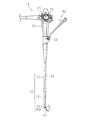
図1は、内視鏡の外観図である。本実施の形態の内視鏡10は、上部消化管向けの軟性鏡である。内視鏡10は、操作部20および挿入部30を有する。操作部20は、起上操作レバー21、チャンネル入口22および湾曲ノブ23を有する。操作部20は、図示しないビデオプロセッサ、光源装置および表示装置等に接続されている。
[Embodiment 1]
FIG. 1 is an external view of the endoscope. The endoscope 10 of the present embodiment is a flexible mirror for the upper gastrointestinal tract. The endoscope 10 has an operation unit 20 and an insertion unit 30. The operation unit 20 has a rise operation lever 21, a channel inlet 22, and a curved knob 23. The operation unit 20 is connected to a video processor, a light source device, a display device, and the like (not shown).

挿入部30は長尺であり、一端が操作部20に接続されている。挿入部30は、操作部20側から順に軟性部12、湾曲部13および内視鏡用キャップ50を有する。軟性部12は、軟性である。湾曲部13は、湾曲ノブ23の操作に応じて湾曲する。内視鏡用キャップ50は、湾曲部13に連続する硬性の先端部31(図2参照)を覆っている。 The insertion portion 30 is long, and one end thereof is connected to the operation portion 20. The insertion portion 30 has a flexible portion 12, a curved portion 13, and an endoscope cap 50 in this order from the operation portion 20 side. The soft portion 12 is soft. The curved portion 13 is curved according to the operation of the curved knob 23. The endoscope cap 50 covers a rigid tip portion 31 (see FIG. 2) continuous with the curved portion 13.

以後の説明では、挿入部30の長手方向を挿入方向と記載する。同様に、挿入方向に沿って操作部20に近い側を操作部側、操作部20から遠い側を先端側と記載する。 In the following description, the longitudinal direction of the insertion portion 30 will be referred to as the insertion direction. Similarly, the side closer to the operation unit 20 along the insertion direction is described as the operation unit side, and the side far from the operation unit 20 is described as the tip side.

図2は、挿入部30の先端の斜視図である。図3は、挿入部30の先端から処置具先端部41が突出した状態を示す説明図である。図1から図3を使用して、本実施の形態の内視鏡10の構成を説明する。 FIG. 2 is a perspective view of the tip of the insertion portion 30. FIG. 3 is an explanatory view showing a state in which the tip portion 41 of the treatment tool protrudes from the tip of the insertion portion 30. The configuration of the endoscope 10 of the present embodiment will be described with reference to FIGS. 1 to 3.

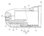
湾曲部13の先端に配置された先端部31は、一方の側に挿入方向に沿って並んだ観察窓36および照明窓37を有する。照明窓37は、観察窓36よりも先端側に配置されている。先端部31は、他方の側の操作部側に、チャンネル出口35を有する。チャンネル出口35の先端側に、起上部83が配置されている。先端部31を覆うカバー52は、観察窓36、照明窓37および起上部83に対応する部分に略長方形の窓部53を有する。窓部53の操作部側の辺は、起上部83側が操作部側に、観察窓36側が先端側にそれぞれ位置する一段の階段状である。 The tip portion 31 arranged at the tip of the curved portion 13 has an observation window 36 and an illumination window 37 arranged on one side along the insertion direction. The illumination window 37 is arranged on the tip side of the observation window 36. The tip portion 31 has a channel outlet 35 on the operation portion side on the other side. A rising portion 83 is arranged on the tip side of the channel outlet 35. The cover 52 that covers the tip portion 31 has a substantially rectangular window portion 53 at a portion corresponding to the observation window 36, the illumination window 37, and the rising portion 83. The side of the window portion 53 on the operation portion side is a one-step step shape in which the rising portion 83 side is located on the operation portion side and the observation window 36 side is located on the tip side.

照明窓37は、図示しない光源装置から出射した照明光を照射する。観察窓36を通して、照明光により照らされた範囲を光学観察することが可能である。本実施の形態の内視鏡10は、光学観察が可能な視野方向が挿入方向に対して交差する方向である、いわゆる側視型である。内視鏡10は、視野方向が若干先端側に傾いた前方斜視型、または視野方向が若干操作部側に傾いた後方斜視型であっても良い。 The illumination window 37 irradiates the illumination light emitted from a light source device (not shown). Through the observation window 36, it is possible to optically observe the range illuminated by the illumination light. The endoscope 10 of the present embodiment is a so-called averted vision type in which the visual field directions at which optical observation is possible intersect with the insertion direction. The endoscope 10 may be a front perspective type in which the visual field direction is slightly tilted toward the tip end side, or a rear perspective type in which the visual field direction is slightly tilted toward the operation unit side.

チャンネル入口22とチャンネル出口35との間は、軟性部12および湾曲部13の内部を通るチャンネル34により接続されている。チャンネル入口22から処置具40を処置具先端部41側から挿入することにより、チャンネル出口35から処置具先端部41を突出させることができる。 The channel inlet 22 and the channel outlet 35 are connected by a channel 34 passing through the inside of the flexible portion 12 and the curved portion 13. By inserting the treatment tool 40 from the channel inlet 22 from the treatment tool tip 41 side, the treatment tool tip 41 can be projected from the channel outlet 35.

図3に実線で示すように、処置具先端部41は起上部83の上で緩く曲がりながら突出する。図1に矢印で示すように、起上操作レバー21を操作すると、後述するようにレバー60(図8参照)が動き、レバー60に連動して起上台80が動く。起上台80が動くことにより、図1中および図3中に矢印および二点鎖線で示すように、起上台80の上の処置具先端部41が操作部20側に屈曲する。処置具先端部41の動きは、観察窓36を介して図示しない撮像素子等により撮影され、図示しない表示装置に表示される。 As shown by the solid line in FIG. 3, the treatment tool tip 41 projects on the rising portion 83 while being gently bent. As shown by an arrow in FIG. 1, when the raising operation lever 21 is operated, the lever 60 (see FIG. 8) moves as described later, and the raising table 80 moves in conjunction with the lever 60. As the rising table 80 moves, the treatment tool tip 41 on the rising table 80 bends toward the operation unit 20, as shown by arrows and alternate long and short dash lines in FIGS. 1 and 3. The movement of the tip portion 41 of the treatment tool is photographed by an image sensor or the like (not shown) through the observation window 36 and displayed on a display device (not shown).

処置具40は、たとえば高周波ナイフ、鉗子または造影チューブ等の処置用の機器である。なお、チャンネル34に挿入する機器は処置用の機器に限定されない。たとえば、超音波プローブ、極細内視鏡等の観察用の機器をチャンネル34に挿入して使用する場合もある。以後の説明では、観察用の機器も含めて処置具40と記載する。 The treatment tool 40 is a treatment device such as a high-frequency knife, forceps, or a contrast tube. The device to be inserted into the channel 34 is not limited to the device for treatment. For example, an observation device such as an ultrasonic probe or an ultrafine endoscope may be inserted into the channel 34 for use. In the following description, the treatment tool 40 including the observation device will be described.

以上に説明したように起上台80が動くことを、以下の説明では「起上台80が起上する」と表現する場合がある。起上した起上台80に押されて処置具先端部41が屈曲することを、以下の説明では「処置具40が起上する」と表現する場合がある。起上操作レバー21の操作により、処置具40の起上の程度を調整することができる。 The movement of the riser 80 as described above may be expressed as "the riser 80 rises" in the following description. The bending of the treatment tool tip 41 by being pushed by the rising stand 80 may be expressed as "the treatment tool 40 rises" in the following description. By operating the raising operation lever 21, the degree of raising of the treatment tool 40 can be adjusted.

図4は、挿入部30の先端の正面図である。カバー52は、開口端部56の近傍に長方形の凹部48を有する。凹部48の各辺は、カバー52の表面から略垂直に立ち下がっている。凹部48は、カバー52の周方向の他の部分に比べて薄肉であり、指で押さえる等により外力を加えると撓み易い部分である。凹部48は、本実施の形態の可撓部の一例である。 FIG. 4 is a front view of the tip of the insertion portion 30. The cover 52 has a rectangular recess 48 in the vicinity of the open end 56. Each side of the recess 48 hangs substantially perpendicular to the surface of the cover 52. The recess 48 is thinner than other parts in the circumferential direction of the cover 52, and is a portion that easily bends when an external force is applied by pressing it with a finger or the like. The recess 48 is an example of a flexible portion of the present embodiment.

本実施の形態の内視鏡10は、内視鏡用キャップ50および起上台80を挿入部30から着脱することが可能である。内視鏡用キャップ50は、外装部材であるカバー52を有する。内視鏡用キャップ50および起上台80の構成の詳細については後述する。 In the endoscope 10 of the present embodiment, the endoscope cap 50 and the raising base 80 can be attached to and detached from the insertion portion 30. The endoscope cap 50 has a cover 52 which is an exterior member. Details of the configuration of the endoscope cap 50 and the riser 80 will be described later.

図5は、内視鏡用キャップ50および起上台80を挿入部30の先端から取り外した状態を説明する正面図である。図6は、内視鏡用キャップ50および起上台80を挿入部30の先端から取り外した状態を説明する背面図である。 FIG. 5 is a front view illustrating a state in which the endoscope cap 50 and the raising base 80 are removed from the tip of the insertion portion 30. FIG. 6 is a rear view illustrating a state in which the endoscope cap 50 and the raising base 80 are removed from the tip of the insertion portion 30.

ユーザは、一方の手で湾曲部13を保持し、他方の手の二本の指でカバー52を摘む。この際、二本の指の一方で凹部48を押さえると、もう一方の指は自然に図6にPで示す領域を押さえる。ユーザは、二本の指でカバー52を押圧して、軽く変形させた後に、先端側に引っ張ることにより、後述するように挿入部30から内視鏡用キャップ50を外すことができる。その後ユーザは、指等を用いて起上台80を先端側に引っ張ることにより、挿入部30から起上台80を外すことができる。 The user holds the curved portion 13 with one hand and picks the cover 52 with two fingers of the other hand. At this time, when the concave portion 48 is pressed by one of the two fingers, the other finger naturally presses the region shown by P in FIG. The user can remove the endoscope cap 50 from the insertion portion 30 by pressing the cover 52 with two fingers, slightly deforming it, and then pulling it toward the tip side. After that, the user can remove the raising table 80 from the insertion portion 30 by pulling the raising table 80 toward the tip side using a finger or the like.

図7は、内視鏡用キャップ50および起上台80を取り外した挿入部30の先端の斜視図である。図5から図7を使用して、挿入部30の先端の構成を説明する。先端部31は、略円柱形状であり、中心からずれた位置に先端側から操作部側に向けて設けられた溝により、光学収容部33とレバー室69とに分かれている。チャンネル出口35は、溝の底に開口している。チャンネル出口35の近傍に、曲げ部27が設けられている。曲げ部27の形状については後述する。 FIG. 7 is a perspective view of the tip of the insertion portion 30 from which the endoscope cap 50 and the raising base 80 have been removed. The configuration of the tip of the insertion portion 30 will be described with reference to FIGS. 5 to 7. The tip portion 31 has a substantially cylindrical shape, and is divided into an optical accommodating portion 33 and a lever chamber 69 by a groove provided from the tip side toward the operation portion side at a position deviated from the center. The channel outlet 35 opens at the bottom of the groove. A bent portion 27 is provided in the vicinity of the channel outlet 35. The shape of the bent portion 27 will be described later.

先端部31は、周面の一部を平坦に切り欠いて形成される第1平面部321を有する。第1平面部321の、光学収容部33とレバー室69とを隔てる溝の底に沿った部分に、第3係合部29が設けてある。第3係合部29は、長円形の窪みである。先端部31は、第3係合部29の裏側に第4係合部28(図6参照)を有する。第4係合部28は、長方形の窪みである。 The tip portion 31 has a first flat portion 321 formed by cutting out a part of the peripheral surface flatly. A third engaging portion 29 is provided at a portion of the first flat surface portion 321 along the bottom of the groove that separates the optical accommodating portion 33 and the lever chamber 69. The third engaging portion 29 is an oval recess. The tip portion 31 has a fourth engaging portion 28 (see FIG. 6) on the back side of the third engaging portion 29. The fourth engaging portion 28 is a rectangular recess.

第1平面部321の光学収容部33側には、観察窓36および照明窓37が配置されている。観察窓36の操作部側には、観察窓36に水および空気を噴射して清掃するノズル38が設けられている。 An observation window 36 and an illumination window 37 are arranged on the optical accommodating portion 33 side of the first flat surface portion 321. On the operation unit side of the observation window 36, a nozzle 38 for injecting water and air into the observation window 36 for cleaning is provided.

レバー室69は中空であり、先端部31の外周面に沿った長方形の薄板状のレバー室蓋67で覆われている。レバー室蓋67は、蓋ねじ66により四隅で固定されている。蓋ねじ66は、本実施の形態の固定部材の一例である。レバー室69は、光学収容部33側に支持壁68を有する。支持壁68から光学収容部33に向けて起上台連結部61が突出する。起上台連結部61は、長方形断面の軸である。起上台連結部61については後述する。 The lever chamber 69 is hollow and is covered with a rectangular thin plate-shaped lever chamber lid 67 along the outer peripheral surface of the tip portion 31. The lever chamber lid 67 is fixed at four corners by lid screws 66. The lid screw 66 is an example of the fixing member of the present embodiment. The lever chamber 69 has a support wall 68 on the optical accommodating portion 33 side. The riser connecting portion 61 projects from the support wall 68 toward the optical accommodating portion 33. The riser connecting portion 61 is an axis having a rectangular cross section. The riser connecting portion 61 will be described later.

図8は、内視鏡用キャップ50、起上台80およびレバー室蓋67を取り外した挿入部30の先端の斜視図である。レバー室69の内部に、レバー60が設けられている。レバー60は、一端にワイヤ固定部65を有し、他端に後述するようにレバー軸63(図17参照)および起上台連結部61を有する。レバー60は、支持壁68に設けた孔に回動可能に支持されている。 FIG. 8 is a perspective view of the tip of the insertion portion 30 from which the endoscope cap 50, the riser 80, and the lever chamber lid 67 have been removed. A lever 60 is provided inside the lever chamber 69. The lever 60 has a wire fixing portion 65 at one end, and a lever shaft 63 (see FIG. 17) and a riser base connecting portion 61 at the other end, as will be described later. The lever 60 is rotatably supported by a hole provided in the support wall 68.

ワイヤ固定部65は、起上ワイヤ24の端部に連結されている。起上ワイヤ24は、挿入部30を通って起上操作レバー21(図1参照)に連結されている。さらに具体的には、起上ワイヤ24は、起上ワイヤ24の外径よりも若干太い内径を有する図示しない案内管に挿通されている。図示しない案内管は、挿入部30を長手方向に貫通する。そのため、起上操作レバー21の操作に連動して起上ワイヤ24の先端が進退する。 The wire fixing portion 65 is connected to the end portion of the rising wire 24. The raising wire 24 is connected to the raising operation lever 21 (see FIG. 1) through the insertion portion 30. More specifically, the raising wire 24 is inserted into a guide pipe (not shown) having an inner diameter slightly larger than the outer diameter of the raising wire 24. A guide tube (not shown) penetrates the insertion portion 30 in the longitudinal direction. Therefore, the tip of the raising wire 24 moves forward and backward in conjunction with the operation of the raising operation lever 21.

起上ワイヤ24の先端により押し引きされることにより、レバー60がレバー軸63を軸として回動する。起上ワイヤ24は、本実施の形態の回動部の一例である。起上ワイヤ24は、起上操作レバー21により遠隔操作される。 By being pushed and pulled by the tip of the raising wire 24, the lever 60 rotates about the lever shaft 63. The raising wire 24 is an example of the rotating portion of the present embodiment. The raising wire 24 is remotely controlled by the raising operation lever 21.

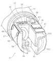
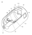
図9は、内視鏡用キャップ50を内視鏡10への取付側からみた斜視図である。図10は、内視鏡用キャップ50をカバー52の底側からみた斜視図である。内視鏡用キャップ50は、カバー52および台座70を有する。カバー52は、一端に開口部を有する有底筒型である。前述のとおり、カバー52の一端の開口部を開口端部56と記載する。 FIG. 9 is a perspective view of the endoscope cap 50 as viewed from the attachment side to the endoscope 10. FIG. 10 is a perspective view of the endoscope cap 50 as viewed from the bottom side of the cover 52. The endoscope cap 50 has a cover 52 and a pedestal 70. The cover 52 is a bottomed tubular type having an opening at one end. As described above, the opening at one end of the cover 52 is referred to as the opening end 56.

前述したようにカバー52は、筒部に窓部53を有する。窓部53は、カバー52の周面の一箇所に、略全長にわたって開口している。カバー52は、窓部53に対向する内面に、開口端部56から底に向けて延びる台座溝45を有する。台座溝45に台座70が固定されている。台座70については後述する。 As described above, the cover 52 has a window portion 53 in the tubular portion. The window portion 53 is opened at one location on the peripheral surface of the cover 52 over a substantially overall length. The cover 52 has a pedestal groove 45 extending from the open end 56 toward the bottom on the inner surface facing the window 53. The pedestal 70 is fixed to the pedestal groove 45. The pedestal 70 will be described later.

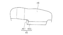
カバー52は、窓部53の開口端部56側の縁に沿って内側に向けて突出する板状の突出部49を有する。突出部49の先端の一部には、第1係合部46が内向きに突出するように設けられている。 The cover 52 has a plate-shaped protrusion 49 that projects inward along the edge of the window 53 on the side of the open end 56. A first engaging portion 46 is provided so as to project inward at a part of the tip of the protruding portion 49.

図11は、第1係合部46の拡大斜視図である。図11は、図9のA部を拡大した図である。図9から図11を使用して、第1係合部46の形状を説明する。第1係合部46は、底側の第1くさび面461と、開口端部56側の第2くさび面462とを有する。第1くさび面461は、突出部49の底側の面に連続し、窓部53の縁に沿う平面である。 FIG. 11 is an enlarged perspective view of the first engaging portion 46. FIG. 11 is an enlarged view of part A in FIG. The shape of the first engaging portion 46 will be described with reference to FIGS. 9 to 11. The first engaging portion 46 has a first wedge surface 461 on the bottom side and a second wedge surface 462 on the open end 56 side. The first wedge surface 461 is a plane that is continuous with the bottom surface of the protrusion 49 and is along the edge of the window 53.

第2くさび面462は、内側を底側に、外側を開口端部56側にして、筒部の軸長方向に対して傾斜する平面である。筒部の軸と平行な面で第1係合部46を切断すると、第1くさび面461と第2くさび面462とは、先細りのくさび形状を形成している。 The second wedge surface 462 is a flat surface that is inclined with respect to the axial length direction of the tubular portion, with the inside facing the bottom side and the outside facing the opening end portion 56 side. When the first engaging portion 46 is cut on a surface parallel to the axis of the tubular portion, the first wedge surface 461 and the second wedge surface 462 form a tapered wedge shape.

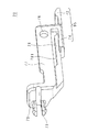
図12は、起上台80の斜視図である。図13は、起上台80の正面図である。図14は、起上台80の側面図である。図12から図14を使用して、起上台80の構成を説明する。 FIG. 12 is a perspective view of the riser 80. FIG. 13 is a front view of the riser 80. FIG. 14 is a side view of the riser 80. The configuration of the riser 80 will be described with reference to FIGS. 12 to 14.

起上台80は、略L字型の起上部83を有する。起上部83は、一面にスプーン状の窪み部84を有する第1起上部831と、第1起上部831の端から第1起上部831の窪み部84を有する面と同じ側に突出する第2起上部832とを有する。 The riser 80 has a substantially L-shaped riser 83. The raised portion 83 has a first raised portion 831 having a spoon-shaped recessed portion 84 on one surface, and a second rising portion 831 projecting from the end of the first raised upper portion 831 to the same side as the surface having the recessed portion 84 of the first raised upper portion 831. It has a raised portion 832.

第2起上部832の端部にレバー連結部81が設けられている。レバー連結部81は、第2起上部832の端部に向けて開口するU字形の溝である。レバー連結部81の開口部の縁、すなわち開口縁には、内向きに突出するレバー抜止部812が設けられている。レバー連結部81の一方は、板状のフランジ85に覆われている。フランジ85の反対側の面から起上台軸82が突出する。 A lever connecting portion 81 is provided at the end of the second rising portion 832. The lever connecting portion 81 is a U-shaped groove that opens toward the end of the second rising portion 832. An inwardly projecting lever retaining portion 812 is provided on the edge of the opening of the lever connecting portion 81, that is, the opening edge. One of the lever connecting portions 81 is covered with a plate-shaped flange 85. The raising base shaft 82 projects from the surface opposite to the flange 85.

すなわち、フランジ85の一方の面から起上台軸82が突出し、フランジ85の他方の面から起上台軸82の中心軸と交差する方向に、起上部83が突出している。起上部83の基端部側に、レバー連結部81が設けられている。 That is, the rising base shaft 82 protrudes from one surface of the flange 85, and the rising base 83 protrudes from the other surface of the flange 85 in a direction intersecting the central axis of the rising base shaft 82. A lever connecting portion 81 is provided on the base end side of the raised portion 83.

第1起上部831の外側、すなわち、窪み部84に隣接する面には、複数の浅い窪みにより形成された滑止部833が設けられている。図12においては、窪みの形状は円形であるが、溝状その他任意の形状であってもよい。 A non-slip portion 833 formed by a plurality of shallow depressions is provided on the outside of the first rising portion 831, that is, on the surface adjacent to the recess portion 84. In FIG. 12, the shape of the recess is circular, but it may be groove-shaped or any other shape.

図14に破線で示すように、レバー連結部81は、起上台軸82の中心軸を挟むように配置されている。 As shown by a broken line in FIG. 14, the lever connecting portion 81 is arranged so as to sandwich the central axis of the raising base shaft 82.

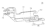
図15は、台座70の斜視図である。図15を使用して、台座70の構成を説明する。台座70は、長方形板状の土台部95と、土台部95の長手方向の中央部から立ち上がる支持足から土台部95の長手方向に沿って延びる略長方形板状の第1壁77とを有する。さらに土台部95から、略長方形板状の第2壁78が第1壁77と平行に立ち上がる。第1壁77と第2壁78とは、土台部95の幅方向に離れている。 FIG. 15 is a perspective view of the pedestal 70. The configuration of the pedestal 70 will be described with reference to FIG. The pedestal 70 has a rectangular plate-shaped base portion 95 and a substantially rectangular plate-shaped first wall 77 extending along the longitudinal direction of the base portion 95 from a support foot rising from a central portion in the longitudinal direction of the base portion 95. Further, from the base portion 95, a substantially rectangular plate-shaped second wall 78 rises in parallel with the first wall 77. The first wall 77 and the second wall 78 are separated from each other in the width direction of the base portion 95.

第1壁77の端部には、第1壁77と第2壁78とを架け渡す長方形板状の第3壁79が接続している。第3壁79には、第1壁77と反対側の面に、第1固定突起73を設けてある。第1固定突起73は、割り溝を有する円柱形の突起である。第1固定突起73は、端部に一回り太い抜け止めを有する。 A rectangular plate-shaped third wall 79 that bridges the first wall 77 and the second wall 78 is connected to the end of the first wall 77. The third wall 79 is provided with a first fixing protrusion 73 on a surface opposite to the first wall 77. The first fixing protrusion 73 is a cylindrical protrusion having a split groove. The first fixing protrusion 73 has a slightly thicker retaining protrusion at the end.

土台部95は、長手方向の第3壁79側で、幅方向の第1壁77側に、他の部分よりも厚くした厚板部741を有する。厚板部741の先端は面取りされている。土台部95は、第3壁79と反対側の端部に、全幅にわたって略半円形に盛り上がる第2係合部72を有する。土台部95の幅は、台座溝45に対応している。 The base portion 95 has a thick plate portion 741 thicker than other portions on the third wall 79 side in the longitudinal direction and on the first wall 77 side in the width direction. The tip of the plank portion 741 is chamfered. The base portion 95 has a second engaging portion 72 that rises in a substantially semicircular shape over the entire width at an end portion opposite to the third wall 79. The width of the base portion 95 corresponds to the pedestal groove 45.

第1壁77は、起上台取付溝761を有する。起上台取付溝761は、第1壁77の根元側の端部に開口を有し、土台部95と平行に伸びる略U字型の溝である。起上台取付溝761の溝幅は、起上台軸82の直径と対応している。 The first wall 77 has a riser mounting groove 761. The riser mounting groove 761 is a substantially U-shaped groove having an opening at the root side end of the first wall 77 and extending in parallel with the base portion 95. The groove width of the riser mounting groove 761 corresponds to the diameter of the riser shaft 82.

図16は、図5のXVI−XVI線による内視鏡用キャップ50の断面図である。XVI−XVI断面は、挿入部30の長手方向に沿って、第1壁77を厚さ方向に切断する断面である。図9から図11、図15および図16を使用して、内視鏡用キャップ50の構成を説明する。 FIG. 16 is a cross-sectional view of the endoscope cap 50 taken along the line XVI-XVI of FIG. The XVI-XVI cross section is a cross section that cuts the first wall 77 in the thickness direction along the longitudinal direction of the insertion portion 30. The configuration of the endoscope cap 50 will be described with reference to FIGS. 9 to 11, 15 and 16.

カバー52の底に、台座固定孔57が設けられている。台座固定孔57は、カバー52の外面の側に太径部を有する段付きの貫通孔である。台座固定孔57の細径部は、カバー52の内面に向けて拡がるテーパ形状である。台座固定孔57の内径は、第1固定突起73の外径と対応している。 A pedestal fixing hole 57 is provided at the bottom of the cover 52. The pedestal fixing hole 57 is a stepped through hole having a large diameter portion on the outer surface side of the cover 52. The small diameter portion of the pedestal fixing hole 57 has a tapered shape that expands toward the inner surface of the cover 52. The inner diameter of the pedestal fixing hole 57 corresponds to the outer diameter of the first fixing protrusion 73.

カバー52は内面に第2固定突起58を有する。第2固定突起58は、台座溝45の端から開口端部56側に向けて張り出す突起である。第2固定突起58と、台座溝45の底との間の距離は、厚板部741の厚さと対応している。 The cover 52 has a second fixing protrusion 58 on the inner surface. The second fixing protrusion 58 is a protrusion that projects from the end of the pedestal groove 45 toward the opening end 56 side. The distance between the second fixing protrusion 58 and the bottom of the pedestal groove 45 corresponds to the thickness of the plate portion 741.

内視鏡用キャップ50の組立方法の概要を説明する。台座70の第1固定突起73側を先にして、土台部95と、カバー52の台座溝45との周方向の位置を合わせる。台座70をカバー52に押し込む。 The outline of the method of assembling the endoscope cap 50 will be described. With the first fixing protrusion 73 side of the pedestal 70 first, the positions of the base portion 95 and the pedestal groove 45 of the cover 52 in the circumferential direction are aligned. Push the pedestal 70 into the cover 52.

第1固定突起73が弾性変形して、台座固定孔57の細径部を通過する。第1固定突起73の抜け止めが台座固定孔57の細径部を通過した後に、第1固定突起73が弾性復帰する。第2固定突起58と厚板部741とが係合する。以上により、台座70とカバー52とが固定される。なお、台座溝45等に接着剤を塗布し、台座70とカバー52とを接着固定しても良い。 The first fixing protrusion 73 is elastically deformed and passes through the small diameter portion of the pedestal fixing hole 57. After the retaining protrusion 73 has passed through the small diameter portion of the pedestal fixing hole 57, the first fixing protrusion 73 elastically returns. The second fixing protrusion 58 and the thick plate portion 741 engage with each other. As described above, the pedestal 70 and the cover 52 are fixed. An adhesive may be applied to the pedestal groove 45 or the like to bond and fix the pedestal 70 and the cover 52.

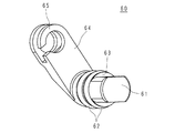
図17は、レバー60の斜視図である。レバー60は、一端にレバー軸63を有し、他端にワイヤ固定部65を有する。レバー軸63の一方の端面から、レバー軸63の中心軸と同じ方向に向けて、長方形断面の軸である起上台連結部61が突出している。以下の説明では、レバー軸63とワイヤ固定部65とを連結する板状の部分を回動連結部64と記載する。回動連結部64は、レバー軸63の起上台連結部61と反対側の端部から、レバー軸63の中心軸と交差する方向に突出している。図8に示すように、回動連結部64はレバー室69内で回動する。 FIG. 17 is a perspective view of the lever 60. The lever 60 has a lever shaft 63 at one end and a wire fixing portion 65 at the other end. A riser connecting portion 61, which is an axis having a rectangular cross section, projects from one end surface of the lever shaft 63 in the same direction as the central axis of the lever shaft 63. In the following description, the plate-shaped portion that connects the lever shaft 63 and the wire fixing portion 65 will be referred to as a rotary connecting portion 64. The rotary connecting portion 64 projects from the end of the lever shaft 63 opposite to the raising base connecting portion 61 in a direction intersecting the central axis of the lever shaft 63. As shown in FIG. 8, the rotary connecting portion 64 rotates in the lever chamber 69.

レバー軸63に、2個のOリング62が取り付けられている。図7に戻って説明を続ける。レバー60は、支持壁68に設けた孔にレバー室69側からレバー軸63が挿入され、起上台連結部61を光学収容部33に向けた状態で、回動可能に支持される。Oリング62とレバー室蓋67とにより、中空のレバー室69は水密に封止される。 Two O-rings 62 are attached to the lever shaft 63. The explanation will be continued by returning to FIG. The lever 60 is rotatably supported with the lever shaft 63 inserted into the hole provided in the support wall 68 from the lever chamber 69 side and the riser base connecting portion 61 facing the optical accommodating portion 33. The hollow lever chamber 69 is watertightly sealed by the O-ring 62 and the lever chamber lid 67.

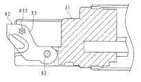
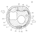
図18は、内視鏡用キャップ50を取り外した挿入部30の先端の断面図である。図18は、図16と同様に図5のXVI−XVI線による断面であり、起上台80を挿入部30の先端に取り付けた状態を示す。 FIG. 18 is a cross-sectional view of the tip of the insertion portion 30 from which the endoscope cap 50 has been removed. FIG. 18 is a cross section taken along the line XVI-XVI of FIG. 5 as in FIG. 16, and shows a state in which the riser 80 is attached to the tip of the insertion portion 30.

図7を使用して説明した起上台連結部61と、図12を使用して説明したレバー連結部81とが係合している。図16を使用して説明した内視鏡用キャップ50が図18の左側から起上台80および先端部31に被せられて、固定される。 The riser connecting portion 61 described with reference to FIG. 7 and the lever connecting portion 81 described with reference to FIG. 12 are engaged with each other. The endoscope cap 50 described with reference to FIG. 16 is placed on the riser table 80 and the tip portion 31 from the left side of FIG. 18 and fixed.

図19は、図4のXIX−XIX線による挿入部30の断面図である。XIX−XIX断面は、起上台連結部61の位置で、挿入部30を長手方向に切断する断面である。図20は、図4のXX−XX線による挿入部30の断面図である。XX−XX断面は、起上台軸82の位置で、挿入部30を長手方向に切断する断面である。図21は、図20のXXI−XXI線による挿入部30の断面図である。XXI−XXI断面は、起上台軸82の位置で、挿入部30の長手方向に対して垂直に切断する断面である。図19から図21を使用して、起上台80および内視鏡用キャップ50を挿入部30の先端に固定する構成について説明する。 FIG. 19 is a cross-sectional view of the insertion portion 30 by the XIX-XIX line of FIG. The XIX-XIX cross section is a cross section that cuts the insertion portion 30 in the longitudinal direction at the position of the riser base connecting portion 61. FIG. 20 is a cross-sectional view of the insertion portion 30 taken along the line XX-XX of FIG. The XX-XX cross section is a cross section that cuts the insertion portion 30 in the longitudinal direction at the position of the rising base shaft 82. FIG. 21 is a cross-sectional view of the insertion portion 30 taken along the line XXI-XXI of FIG. The XXI-XXI cross section is a cross section that cuts at the position of the rising base shaft 82 perpendicular to the longitudinal direction of the insertion portion 30. A configuration in which the riser 80 and the endoscope cap 50 are fixed to the tip of the insertion portion 30 will be described with reference to FIGS. 19 to 21.

内視鏡用キャップ50は、開口端部56を先端部31側に向けている。図19に示すように、内視鏡用キャップ50の内面の第1係合部46と先端部31の第3係合部29とが係合している。係合部では、第1くさび面461と第3係合部29の操作部側の面とが当接している。 The endoscope cap 50 has an open end 56 facing the tip 31 side. As shown in FIG. 19, the first engaging portion 46 on the inner surface of the endoscope cap 50 and the third engaging portion 29 of the tip portion 31 are engaged. In the engaging portion, the first wedge surface 461 and the surface of the third engaging portion 29 on the operation portion side are in contact with each other.

同様に、内視鏡用キャップ50の内面の第2係合部72と先端部31の第4係合部28とが係合している。内視鏡用キャップ50が内面の対向する2箇所で先端部31と係合していることにより、内視鏡用キャップ50が先端部31に固定されている。 Similarly, the second engaging portion 72 on the inner surface of the endoscope cap 50 and the fourth engaging portion 28 of the tip portion 31 are engaged. The endoscope cap 50 is fixed to the tip 31 by engaging the endoscope cap 50 with the tip 31 at two opposite points on the inner surface.

U字溝型のレバー連結部81に長方形断面の軸である起上台連結部61が挿入されている。これにより、レバー60と起上台80とが係合している。レバー連結部81の開口部の縁に設けられたレバー抜止部812の作用により、起上台連結部61がレバー連結部81から抜けない。レバー抜止部812は、本実施の形態の起上台固定部の一例である。 A riser base connecting portion 61, which is an axis having a rectangular cross section, is inserted into the U-shaped groove-shaped lever connecting portion 81. As a result, the lever 60 and the riser 80 are engaged with each other. Due to the action of the lever retaining portion 812 provided on the edge of the opening of the lever connecting portion 81, the riser base connecting portion 61 does not come off from the lever connecting portion 81. The lever retaining portion 812 is an example of the riser base fixing portion of the present embodiment.

図20に示すように、起上台取付溝761と起上台軸82とが係合する。起上台80は、起上台取付溝761と起上台連結部61とにより両持ち支持される。図21に示すように、レバー軸63と起上台軸82とは同軸である。起上台80は、レバー軸63および起上台軸82まわりに、滑らかに回動する。 As shown in FIG. 20, the riser base mounting groove 761 and the riser base shaft 82 are engaged with each other. The riser 80 is supported by the riser mounting groove 761 and the riser connecting portion 61. As shown in FIG. 21, the lever shaft 63 and the raising base shaft 82 are coaxial. The riser 80 smoothly rotates around the lever shaft 63 and the riser shaft 82.

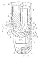
図22は、図4のXXII−XXII線による挿入部30の断面図である。光学収容部33の外側には、先端部31の周面の一部を平坦に切り欠いて形成される第2平面部322および第3平面部323が設けられている。第2平面部322と第3平面部323とは、角度をもって連続している。 FIG. 22 is a cross-sectional view of the insertion portion 30 taken along the line XXII-XXII of FIG. On the outside of the optical accommodating portion 33, a second flat surface portion 322 and a third flat surface portion 323 formed by flatly cutting out a part of the peripheral surface of the tip portion 31 are provided. The second flat surface portion 322 and the third flat surface portion 323 are continuous at an angle.

カバー52の筒部の内面と、第2平面部322および第3平面部323とが空間を隔てて対向して、第1空洞部93を形成している。凹部48は、第1空洞部93に対応する位置に配置されている。凹部48の反対側では、カバー52は筒部の内面をへこませて薄肉にされている。カバー52の薄肉な部分の内面と、レバー室蓋67とが空間を隔てて対向して、第2空洞部94を形成している。第2空洞部94内に、蓋ねじ66の頭部が配置されている。すなわち、第2空洞部94は、レバー室蓋67を固定する固定部材である蓋ねじ66の頭部を収容する空間である。 The inner surface of the tubular portion of the cover 52 and the second flat surface portion 322 and the third flat surface portion 323 face each other with a space between them to form the first cavity portion 93. The recess 48 is arranged at a position corresponding to the first cavity 93. On the opposite side of the recess 48, the cover 52 is thinned by denting the inner surface of the tubular portion. The inner surface of the thin portion of the cover 52 and the lever chamber lid 67 face each other with a space between them to form the second cavity portion 94. The head of the lid screw 66 is arranged in the second cavity portion 94. That is, the second cavity portion 94 is a space for accommodating the head of the lid screw 66, which is a fixing member for fixing the lever chamber lid 67.

内視鏡用キャップ50を取り外す場合には、図22に白抜き矢印で示すように、凹部48と、その反対側との2箇所をユーザが指で押圧する。押圧する部分の裏側に第1空洞部93および第2空洞部94が存在するため、カバー52は変形する。なお、前述のとおり凹部48は、カバー52の周方向の他の部分に比べて薄肉であり、指で押さえる等により撓み易い可撓部である。 When removing the endoscope cap 50, the user presses the recess 48 and the opposite side with a finger as shown by the white arrows in FIG. 22. Since the first cavity portion 93 and the second cavity portion 94 are present on the back side of the pressing portion, the cover 52 is deformed. As described above, the recess 48 is thinner than the other parts in the circumferential direction of the cover 52, and is a flexible portion that is easily bent by being pressed by a finger or the like.

ユーザは、指で押圧することにより、容易に内視鏡用キャップ50を変形させることができる。この変形により、第1係合部46と第3係合部29との係合、および、第2係合部72と第4係合部28との係合が外れる。 The user can easily deform the endoscope cap 50 by pressing with a finger. Due to this deformation, the engagement between the first engaging portion 46 and the third engaging portion 29 and the engagement between the second engaging portion 72 and the fourth engaging portion 28 are disengaged.

ユーザが、内視鏡用キャップ50を押圧したまま先端側に引くことにより、起上台軸82が起上台取付溝761から抜ける。以上により、ユーザは内視鏡用キャップ50を挿入部30から外すことができる。 When the user pulls the endoscope cap 50 toward the tip while pressing it, the raising base shaft 82 comes out of the raising base mounting groove 761. As described above, the user can remove the endoscope cap 50 from the insertion portion 30.

その後、ユーザは起上台80を指等により摘んで先端側に引っ張ることにより、起上台80を挿入部30から外すことができる。摘む位置には滑止部833が設けてあるので滑りにくく、ユーザは起上台80を容易に外すことができる。 After that, the user can remove the raising table 80 from the insertion portion 30 by picking the raising table 80 with a finger or the like and pulling it toward the tip end side. Since the non-slip portion 833 is provided at the picking position, it is hard to slip, and the user can easily remove the riser table 80.

起上台80および内視鏡用キャップ50を挿入部30の先端に取り付ける手順について説明する。ユーザは、起上台80の滑止部833を指等で摘む。ユーザは、起上台連結部61とレバー連結部81との向きを合わせる。 The procedure for attaching the riser 80 and the endoscope cap 50 to the tip of the insertion portion 30 will be described. The user picks the non-slip portion 833 of the riser 80 with a finger or the like. The user aligns the riser base connecting portion 61 with the lever connecting portion 81.

ユーザは、起上台80を挿入部30の先端側から差し込み、起上台連結部61に、レバー連結部81を押し当てる。起上台80が弾性変形してレバー抜止部812間の間隔が広がる。レバー抜止部812の間を通って、起上台連結部61がレバー連結部81の奥に入る。起上台80が弾性復帰して、レバー抜止部812の間隔が元に戻る。 The user inserts the riser 80 from the tip side of the insertion portion 30, and presses the lever connecting portion 81 against the riser connecting portion 61. The riser 80 is elastically deformed to widen the distance between the lever retaining portions 812. The riser base connecting portion 61 enters the back of the lever connecting portion 81 through the lever retaining portion 812. The riser 80 is elastically restored, and the distance between the lever retaining portions 812 is restored.

図19および図20を使用して説明したように、起上台連結部61とレバー連結部81とが係合し、起上台連結部61がレバー連結部81から抜けない状態になる。以上により、ユーザは起上台80を挿入部30の先端に取り付けることができる。 As described with reference to FIGS. 19 and 20, the riser base connecting portion 61 and the lever connecting portion 81 are engaged with each other, and the raising base connecting portion 61 is not disengaged from the lever connecting portion 81. As described above, the user can attach the riser 80 to the tip of the insertion portion 30.

その後ユーザは、窓部53と窪み部84とを目印として、先端部31に対して内視鏡用キャップ50の周方向の位置を合わせる。ユーザは、内視鏡用キャップ50を挿入部30の先端に押し込む。図11に示すように、第1係合部46の第2くさび面462は、前記カバー52の筒部の長手方向に対して傾斜しているので、第1係合部46が先端部31に引っ掛かりにくい。 After that, the user aligns the position of the endoscope cap 50 in the circumferential direction with respect to the tip portion 31 using the window portion 53 and the recessed portion 84 as markers. The user pushes the endoscope cap 50 into the tip of the insertion portion 30. As shown in FIG. 11, since the second wedge surface 462 of the first engaging portion 46 is inclined with respect to the longitudinal direction of the tubular portion of the cover 52, the first engaging portion 46 is attached to the tip portion 31. Hard to get caught.

第1係合部46は、弾性変形しながら第3係合部29の中に押し込まれる。第1係合部46は、第1くさび面461が第3係合部29内に入った時点で弾性復帰して第3係合部29と係合する。 The first engaging portion 46 is pushed into the third engaging portion 29 while being elastically deformed. The first engaging portion 46 elastically returns when the first wedge surface 461 enters the third engaging portion 29 and engages with the third engaging portion 29.

図19に示すように、第2係合部72は略半円形に盛り上がる突起なので第4係合部28の内部に押し込まれ易い。第2係合部72も、弾性変形しながら第4係合部28の中に押し込まれる。第2係合部72は、第4係合部28内に入った時点で弾性復帰して、第4係合部28と係合する。 As shown in FIG. 19, since the second engaging portion 72 is a protrusion that rises in a substantially semicircular shape, it is easily pushed into the inside of the fourth engaging portion 28. The second engaging portion 72 is also pushed into the fourth engaging portion 28 while being elastically deformed. The second engaging portion 72 elastically returns when it enters the fourth engaging portion 28 and engages with the fourth engaging portion 28.

以上により、ユーザは内視鏡用キャップ50を挿入部30の先端に容易に取り付けることができる。 As described above, the user can easily attach the endoscope cap 50 to the tip of the insertion portion 30.

図19に示すように、チューブ状のチャンネル34は先端部31に設けられたチャンネル出口35に接続されている。チャンネル出口35は、窓部53に向けてラッパ状に拡がっている。チャンネル出口35の第3係合部29近傍、すなわちチャンネル出口35からみて起上台80が起上する側の周縁部に、先端側に向けてゆるやかに突出する曲げ部27が設けられている。 As shown in FIG. 19, the tubular channel 34 is connected to a channel outlet 35 provided at the tip portion 31. The channel outlet 35 extends in a trumpet shape toward the window portion 53. A bent portion 27 that gently protrudes toward the tip end side is provided in the vicinity of the third engaging portion 29 of the channel outlet 35, that is, on the peripheral edge portion on the side where the raising base 80 rises when viewed from the channel outlet 35.

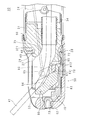
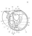
図23は、起上台80を起上した挿入部30の断面図である。図23は、図20と同一の断面を示す。図7、図8、図17、図19、図21および図23を使用して、起上台80を起上させる構成を説明する。 FIG. 23 is a cross-sectional view of the insertion portion 30 in which the raising table 80 is raised. FIG. 23 shows the same cross section as in FIG. A configuration for raising the raising table 80 will be described with reference to FIGS. 7, 8, 17, 19, 21, and 23.

レバー室69側から支持壁68に設けられた貫通孔にレバー軸63が挿通され、図7に示すように起上台連結部61が支持壁68の反対側に突出している。前述のとおり、レバー室69は、Oリング62およびレバー室蓋67により、水密に封止されている。したがって、内視鏡10の使用中にレバー室69の内部および起上ワイヤ24の経路に体液等が付着しない。 The lever shaft 63 is inserted from the lever chamber 69 side into a through hole provided in the support wall 68, and the riser base connecting portion 61 projects to the opposite side of the support wall 68 as shown in FIG. As described above, the lever chamber 69 is watertightly sealed by the O-ring 62 and the lever chamber lid 67. Therefore, during the use of the endoscope 10, body fluids and the like do not adhere to the inside of the lever chamber 69 and the path of the raising wire 24.

図19に示す状態では、起上台80はカバー52の内側に収容されている。窪み部84は、チャンネル出口35から突出した処置具先端部41を図19の上方向にゆるやかに曲げることが可能な位置に配置されている。 In the state shown in FIG. 19, the riser 80 is housed inside the cover 52. The recessed portion 84 is arranged at a position where the tip portion 41 of the treatment tool protruding from the channel outlet 35 can be gently bent upward in FIG.

前述のとおり、ユーザが起上操作レバー21を操作することにより、レバー60がレバー軸63を軸として回動する。起上台連結部61は、レバー軸63と一体に回動する。図21を使用して説明したとおり、レバー軸63と、起上台軸82とは同軸である。起上台連結部61がレバー連結部81と連結しているため、起上台80もレバー60と一体となって回動する。その結果、起上台80と窓部53との間の距離が変化する。 As described above, when the user operates the raising operation lever 21, the lever 60 rotates about the lever shaft 63. The riser base connecting portion 61 rotates integrally with the lever shaft 63. As described with reference to FIG. 21, the lever shaft 63 and the riser shaft 82 are coaxial. Since the raising table connecting portion 61 is connected to the lever connecting portion 81, the raising table 80 also rotates integrally with the lever 60. As a result, the distance between the riser 80 and the window 53 changes.

図23は、起上台80が回動して起上した状態を示す。起上台80に押されて、チャンネル出口35から突出した処置具先端部41が起上する。処置具先端部41は、曲げ部27の先端に押し付けられた状態から、さらに窪み部84の先端側の縁によって操作部側に押し込まれる。 FIG. 23 shows a state in which the raising table 80 is rotated and raised. Pushed by the riser 80, the treatment tool tip 41 protruding from the channel outlet 35 rises. The treatment tool tip 41 is further pushed toward the operation portion by the edge on the tip side of the recess 84 from the state of being pressed against the tip of the bending portion 27.

本実施の形態の内視鏡10の使用方法の概要を説明する。内視鏡10は、起上台80および内視鏡用キャップ50を外し、洗浄等を行った状態で保管されている。起上台80および内視鏡用キャップ50は、それぞれ一個ずつ、または、一組ずつ滅菌パックに封入した上で、たとえば10個単位または10組単位で紙箱に入れた後に電子線滅菌を行った状態で提供される。紙箱に入れる起上台80および内視鏡用キャップ50の数は最小販売単位、すなわち1回にユーザに販売される最小単位であることが望ましい。 An outline of how to use the endoscope 10 of the present embodiment will be described. The endoscope 10 is stored in a state where the riser 80 and the endoscope cap 50 have been removed and cleaned. The riser 80 and the endoscope cap 50 are each enclosed in a sterilization pack one by one or in pairs, and then placed in a paper box in units of 10 or 10 and then subjected to electron beam sterilization. Provided at. It is desirable that the number of the riser 80 and the endoscope cap 50 to be put in the paper box is the minimum sales unit, that is, the minimum unit sold to the user at one time.

なお、内視鏡用キャップ50の構成部品であるカバー52および台座70の材料、および、起上台80の材料は、耐放射線グレードのポリエーテルエーテルケトンまたはポリカーボネート等の、電子線滅菌への耐久性が高い材料であることが望ましい。 The materials of the cover 52 and the pedestal 70, which are the components of the endoscope cap 50, and the material of the raising pedestal 80 are made of radiation-resistant grade polyetheretherketone or polycarbonate, and have durability against electron beam sterilization. Is desirable to be a high material.

ユーザは、滅菌パックから起上台80を取り出す。ユーザは、前述の手順により起上台80を内視鏡10に取り付ける。その後、ユーザは、滅菌パックから内視鏡用キャップ50を取り出す。ユーザは前述の手順により内視鏡用キャップ50を挿入部30に取り付ける。ユーザは内視鏡用キャップ50を軽く引っ張る等して、内視鏡用キャップ50が挿入部30の先端にしっかりと固定されていることを確認する。 The user removes the riser 80 from the sterilization pack. The user attaches the riser 80 to the endoscope 10 by the above procedure. The user then removes the endoscopic cap 50 from the sterilization pack. The user attaches the endoscope cap 50 to the insertion portion 30 by the above procedure. The user confirms that the endoscope cap 50 is firmly fixed to the tip of the insertion portion 30 by lightly pulling the endoscope cap 50 or the like.

ユーザは、挿入部30を検査対象者の口から挿入する。観察窓36を介して撮影した映像を観察しながら、ユーザは挿入部30の先端を目的部位に誘導する。ユーザは、目的に応じた処置具40等をチャンネル入口22から挿入する。処置具先端部41が挿入部30の先端から突出し、目的部位の近傍に位置することを確認した後に、ユーザは起上操作レバー21を操作して、処置具先端部41を目的部位に誘導する。必要な処置等を行った後に、ユーザは処置具40をチャンネル34から抜去する。ユーザは内視鏡10を検査対象者から抜去して、検査または処置を終了する。 The user inserts the insertion unit 30 through the mouth of the person to be inspected. While observing the image taken through the observation window 36, the user guides the tip of the insertion portion 30 to the target site. The user inserts the treatment tool 40 or the like according to the purpose from the channel entrance 22. After confirming that the treatment tool tip 41 protrudes from the tip of the insertion portion 30 and is located near the target site, the user operates the raising operation lever 21 to guide the treatment tool tip 41 to the target site. .. After performing the necessary treatment and the like, the user removes the treatment tool 40 from the channel 34. The user removes the endoscope 10 from the person to be examined and ends the examination or treatment.

検査または処置の終了後、ユーザは、前述のように二本の指でカバー52を押圧しながら先端側に引っ張ることにより、内視鏡用キャップ50を内視鏡10から取り外す。起上台80は、挿入部30の先端に残る。ユーザは、残った起上台80を指等により摘んで先端側に引っ張る。レバー連結部81が弾性変形して、レバー抜止部812同士の間隔が広がることにより、起上台80が起上台連結部61から外れる。 After the examination or treatment is completed, the user removes the endoscope cap 50 from the endoscope 10 by pulling the cover 52 toward the tip side while pressing the cover 52 with two fingers as described above. The riser 80 remains at the tip of the insertion portion 30. The user picks up the remaining raising table 80 with a finger or the like and pulls it toward the tip side. The lever connecting portion 81 is elastically deformed, and the distance between the lever retaining portions 812 is widened, so that the raising base 80 is detached from the raising base connecting portion 61.

なお、内視鏡10を通常の方法で使用して、観察および処置を行う際には、カバー52の2箇所に同時に、カバー52を変形させる程度の外力が加わることは考えにくい。フランジ85が、レバー連結部81の一方の面を覆っていることにより、レバー連結部81の剛性が高められている。そのため、内視鏡10を通常の方法で使用して、観察および処置を行う際には、レバー連結部81が変形して起上台連結部61から外れる程度の外力が加わることも考えにくい。 When observing and treating the endoscope 10 by using the endoscope 10 in a usual manner, it is unlikely that an external force sufficient to deform the cover 52 is applied to the two places of the cover 52 at the same time. Since the flange 85 covers one surface of the lever connecting portion 81, the rigidity of the lever connecting portion 81 is increased. Therefore, when the endoscope 10 is used in a usual manner for observation and treatment, it is unlikely that the lever connecting portion 81 is deformed and an external force is applied to the extent that the lever connecting portion 81 is disengaged from the riser connecting portion 61.

ユーザは、内視鏡用キャップ50および起上台80を外した後の内視鏡10に対して、次回の使用に備えて洗浄等の処理を行う。起上台80を固定する際に用いる起上台連結部61は、図7に示すように、先端部31に露出している。 The user performs a process such as cleaning the endoscope 10 after removing the endoscope cap 50 and the raising table 80 in preparation for the next use. As shown in FIG. 7, the riser base connecting portion 61 used when fixing the riser base 80 is exposed to the tip portion 31.

以上により、本実施の形態の内視鏡10は、起上台80付近の複雑な構造を洗浄するための特別な洗浄作業等を必要としない。前述のように内視鏡10の使用中にレバー室69の内部および起上ワイヤ24の経路に体液等が付着しないので、これらの部分の洗浄作業等も不要である。 As described above, the endoscope 10 of the present embodiment does not require a special cleaning operation or the like for cleaning a complicated structure near the riser 80. As described above, since body fluids and the like do not adhere to the inside of the lever chamber 69 and the path of the raising wire 24 during the use of the endoscope 10, cleaning work of these parts is also unnecessary.

したがって、症例間の処理時間が短く、効率良く運用することができる、起上台付きの内視鏡10を提供することができる。本実施の形態によると、内視鏡検査手技開始時の操作性の向上、すなわち内視鏡10に起上台80および内視鏡用キャップ50を取り付ける操作を容易にすることと、内視鏡10の洗浄容易化とを両立することができる。 Therefore, it is possible to provide the endoscope 10 with a riser, which has a short processing time between cases and can be operated efficiently. According to the present embodiment, the operability at the start of the endoscopy procedure is improved, that is, the operation of attaching the riser 80 and the endoscope cap 50 to the endoscope 10 is facilitated, and the endoscope 10 It is possible to achieve both ease of cleaning.

起上台80のレバー連結部81付近の構成について説明する。図23を使用して説明したように処置具先端部41を起上した場合、処置具40自体の弾性により、起上台80には図23に白抜き矢印で示すように、押し戻す方向の力が加わる。そのため、図23中のH部、すなわち、窪み部84に近い側のレバー連結部81の縁に、引張応力が生じる。 The configuration of the riser 80 near the lever connecting portion 81 will be described. When the treatment tool tip 41 is raised as described with reference to FIG. 23, due to the elasticity of the treatment tool 40 itself, the raising table 80 is subjected to a force in the pushing-back direction as shown by the white arrow in FIG. Join. Therefore, tensile stress is generated in the H portion in FIG. 23, that is, the edge of the lever connecting portion 81 on the side close to the recessed portion 84.

H部に生じる応力が、起上台80の降伏応力を超えた場合、起上台80は大きく変形し、処置具先端部41を起上できなくなる。したがって、処置具先端部41を起上した際にH部に生じる応力が、降伏応力を超えないように、起上台80を構成する必要がある。 When the stress generated in the H portion exceeds the yield stress of the riser 80, the riser 80 is greatly deformed and the tip portion 41 of the treatment tool cannot be raised. Therefore, it is necessary to configure the raising table 80 so that the stress generated in the H portion when the tip portion 41 of the treatment tool is raised does not exceed the yield stress.

H部に生じる応力は、使用する処置具40の太さおよび硬さによって異なる。H部に生じる応力は、起上時の挿入部30の形状、および、処置具先端部41の突出長さ等の、様々な要因の影響も受ける。引張降伏応力が40メガパスカル以上の材料を用いることにより、膵胆管領域の様々な診断および治療に使用する内視鏡10に適した起上台80を提供できる。 The stress generated in the H portion depends on the thickness and hardness of the treatment tool 40 used. The stress generated in the H portion is also affected by various factors such as the shape of the insertion portion 30 at the time of rising and the protruding length of the treatment tool tip portion 41. By using a material having a tensile yield stress of 40 megapascals or more, it is possible to provide a riser 80 suitable for the endoscope 10 used for various diagnosis and treatment of the pancreatobiliary region.

起上台80には、引張降伏応力が50メガパスカル以上の材料を用いることがさらに望ましい。起上台80には、引張降伏応力が55メガパスカル以上の材料を用いることがさらに望ましい。起上台80には、引張降伏応力がさらに高い材料を用いても良い。起上台80に使用する材料の引張降伏応力の上限は、起上台80を製作可能な任意の材料の上限であり、たとえば500メガパスカルである。 It is more desirable to use a material having a tensile yield stress of 50 megapascals or more for the riser 80. It is more desirable to use a material having a tensile yield stress of 55 megapascals or more for the riser 80. A material having a higher tensile yield stress may be used for the riser 80. The upper limit of the tensile yield stress of the material used for the riser 80 is the upper limit of any material from which the riser 80 can be manufactured, for example 500 megapascals.

起上台80が樹脂製である場合には、材料の引張降伏応力は、JIS(Japan Industrial Standard)K7161−2:2014(ISO(International Standard Organization)527−2:2012)「プラスチック−引張特性の求め方−第2部:型成形,押出成形及び注型プラスチックの試験条件」に基づいて評価される。 When the riser 80 is made of resin, the tensile yield stress of the material is JIS (Japan Industrial Standard) K7161-2: 2014 (ISO (International Standard Organization) 527-2: 2012). Method-Part 2: Evaluation based on "Test conditions for mold molding, extrusion molding and casting plastic".

図14を参照して、起上台80のレバー連結部81付近の望ましい寸法について説明する。以下の説明では、U字溝型であるレバー連結部81の溝幅をK、窪み部84側の壁の厚さをL、窪み部84と反対側の壁の厚さをJで示し、JとKとLとの合計をMで示す。 With reference to FIG. 14, desirable dimensions in the vicinity of the lever connecting portion 81 of the raising table 80 will be described. In the following description, the groove width of the lever connecting portion 81, which is a U-shaped groove, is indicated by K, the thickness of the wall on the recessed portion 84 side is indicated by L, and the thickness of the wall opposite to the recessed portion 84 is indicated by J. And K and L are indicated by M.

レバー連結部81付近の形状は、(1)式から(3)式までを満たすことが望ましい。
J≧0.25M ‥‥‥ (1)
L≧0.25M ‥‥‥ (2)
0.25M≦K≦0.45M ‥‥‥ (3)
(1)式および(2)式を満たすことにより、レバー連結部81の強度を確保して、変形を防ぐことができる。(3)式を満たすことにより、内視鏡10の先端部の大径化を防ぐことができる。
It is desirable that the shape near the lever connecting portion 81 satisfies the equations (1) to (3).
J ≧ 0.25M ‥‥‥ (1)
L ≧ 0.25M ‥‥‥ (2)
0.25M ≤ K ≤ 0.45M ... (3)
By satisfying the equations (1) and (2), the strength of the lever connecting portion 81 can be ensured and deformation can be prevented. By satisfying the equation (3), it is possible to prevent the diameter of the tip of the endoscope 10 from increasing.

Mは5ミリメートル以下であることが、内視鏡10の先端部の太径化を防ぐ上で望ましい。Mは4.5ミリメートル以下であることが、さらに望ましい。 It is desirable that M is 5 mm or less in order to prevent the diameter of the tip of the endoscope 10 from increasing. It is more desirable that M is 4.5 mm or less.

起上台80が、65メガパスカル程度引張降伏応力を有するポリカーボネート製である場合には、JおよびLは1.3ミリメートル以上であることが、起上台80の破損を防止する上で望ましい。JおよびLは、1.4ミリメートル以上であることがさらに望ましい。 When the riser 80 is made of polycarbonate having a tensile yield stress of about 65 megapascals, it is desirable that J and L be 1.3 mm or more in order to prevent damage to the riser 80. It is more desirable that J and L are 1.4 mm or more.

応力集中によるレバー連結部81の破損を防止する上でレバー連結部81の内面は、図14に半径R1および半径R2で示す丸みを有することが望ましい。半径R1および半径R2は、0.7ミリメートル以上であることが望ましい。半径R1および半径R2は、0.9ミリメートル以上であることがさらに望ましい。 In order to prevent damage to the lever connecting portion 81 due to stress concentration, it is desirable that the inner surface of the lever connecting portion 81 has the roundness shown by the radius R1 and the radius R2 in FIG. The radius R1 and the radius R2 are preferably 0.7 mm or more. It is more desirable that the radius R1 and the radius R2 are 0.9 mm or more.

本実施の形態の内視鏡10は、起上台80を備えており側視型であるので、十二指腸および膵胆管領域の診断および処置用に適している。特に、ERCP(Endoscopic Retrograde Cholangio Pancreatography)、EST(Endoscopic Sphincterotomy)、EBD(Endoscopic Biliary Drainage)等の手技を実施する場合には、本実施の形態の内視鏡10が適している。これらの手技では、十二指腸壁にある十二指腸乳頭部ならびに十二指腸乳頭部に開口する膵管および総胆管等の内部に処置具40を誘導して、処置等を行うためである。 Since the endoscope 10 of the present embodiment includes a riser 80 and is a lateral view type, it is suitable for diagnosis and treatment of the duodenum and pancreatobiliary region. In particular, when performing procedures such as ERCP (Endoscopic Retrograde Cholangio Pancreatography), EST (Endoscopic Sphincterotomy), and EBD (Endoscopic Biliary Drainage), the endoscope 10 of the present embodiment is suitable. This is because in these procedures, the treatment tool 40 is guided into the duodenal papilla on the duodenal wall and the pancreatic duct and the common bile duct that open into the duodenal papilla to perform treatment and the like.

なお、側視型の内視鏡10を、側視内視鏡と呼ぶ場合がある。同様に、十二指腸および膵胆管領域の診断等に適した内視鏡10を、十二指腸内視鏡と呼ぶ場合がある。 The side-view type endoscope 10 may be referred to as a side-view endoscope. Similarly, an endoscope 10 suitable for diagnosing the duodenal and pancreatobiliary regions may be referred to as a duodenal endoscope.

本実施の形態によると、台座70と、カバー52とが別体であるので、それぞれの形状が単純である。そのため、たとえば射出成形等により安価に製造することが可能である。 According to the present embodiment, since the pedestal 70 and the cover 52 are separate bodies, the shapes of the pedestals 70 and the cover 52 are simple. Therefore, it can be manufactured at low cost by, for example, injection molding.

仕様の異なる複数の種類の内視鏡用キャップ50から、ユーザが手技に応じた仕様の内視鏡用キャップ50を選択して使用するようにしても良い。たとえば超音波プローブまたは極細内視鏡等の高価で精密な機器を組み合わせて使用する場合に、過剰な屈曲による機器の破損を防止することを目的として、起上台80の回動可能範囲を狭く制限する機能を備えた内視鏡用キャップ50が提供されても良い。 The user may select and use the endoscope cap 50 having specifications according to the procedure from a plurality of types of endoscope caps 50 having different specifications. For example, when using an expensive and precise device such as an ultrasonic probe or an ultrafine endoscope in combination, the rotatable range of the riser 80 is narrowly limited for the purpose of preventing damage to the device due to excessive bending. An endoscope cap 50 having a function of performing the function may be provided.

起上台80に設けられた窪み部84は、処置具先端部41を保持して左右にぶれにくくする機能を果たす。窪み部84の形状の異なる複数の種類の起上台80から、ユーザが手技に応じた仕様の起上台80を選択して使用するようにしても良い。たとえば、ガイドワイヤ等の細い処置具40を精密に操作することが必要な手技においては、細い処置具40に適した窪み部84を備える起上台80を使用する。 The recessed portion 84 provided in the raising table 80 functions to hold the tip portion 41 of the treatment tool and prevent it from shaking from side to side. The user may select and use the riser 80 having specifications according to the procedure from a plurality of types of risers 80 having different shapes of the recessed portion 84. For example, in a procedure that requires precise operation of a thin treatment tool 40 such as a guide wire, a raising table 80 having a recess 84 suitable for the thin treatment tool 40 is used.

このようにすることにより、用途に適した起上台80および内視鏡用キャップ50をユーザが選択して使用することが可能な内視鏡10を提供することができる。なお、用途ごとに推奨する組合せの起上台80と内視鏡用キャップ50とをセットにした状態で提供されても良い。 By doing so, it is possible to provide the endoscope 10 in which the user can select and use the riser 80 and the endoscope cap 50 suitable for the intended use. It should be noted that the rising table 80 and the endoscope cap 50 of the combination recommended for each application may be provided as a set.

内視鏡10は、先端に超音波振動子を備えるいわゆる超音波内視鏡でも良い。この場合には、内視鏡用キャップ50は、底に超音波振動子を挿通する孔を有することが望ましい。内視鏡10は、下部消化管向けの内視鏡でも良い。内視鏡10は、硬性の挿入部30を備えるいわゆる硬性鏡でも良い。内視鏡10は、エンジンおよび配管等の検査等に使用する、いわゆる工業用内視鏡でも良い。 The endoscope 10 may be a so-called ultrasonic endoscope having an ultrasonic transducer at its tip. In this case, it is desirable that the endoscope cap 50 has a hole in the bottom through which the ultrasonic vibrator is inserted. The endoscope 10 may be an endoscope for the lower gastrointestinal tract. The endoscope 10 may be a so-called rigid mirror provided with a rigid insertion portion 30. The endoscope 10 may be a so-called industrial endoscope used for inspection of an engine, piping, or the like.

本実施の形態の内視鏡用キャップ50および起上台80は、いずれもいわゆるシングルユースであり、一回使用した後に廃棄される。 The endoscope cap 50 and the riser 80 of the present embodiment are both so-called single-use, and are discarded after being used once.

内視鏡用キャップ50は、再使用可能であっても良い。このようにする場合には、挿入部30から取り外した内視鏡用キャップ50をユーザが目視で点検し、破損していない場合には洗浄等の処理を行い再使用する。内視鏡用キャップ50の開口端部56は大きく開いているため、挿入部30に取り付けられたままの状態に比べて容易に洗浄等の処理を行うことができる。内視鏡用キャップ50は小型であるので、滅菌パックに入れて、たとえばオートクレーブ滅菌等を行うことも容易である。 The endoscope cap 50 may be reusable. In this case, the user visually inspects the endoscope cap 50 removed from the insertion portion 30, and if it is not damaged, it is cleaned and reused. Since the open end 56 of the endoscope cap 50 is wide open, it is possible to easily perform a process such as cleaning as compared with the state where the cap 50 is still attached to the insertion portion 30. Since the endoscope cap 50 is small, it is easy to put it in a sterilization pack and perform, for example, autoclave sterilization.

内視鏡用キャップ50を、カバー52と台座70とに分解した後に、洗浄等の処理を行い、組み立てなおしてから再使用するようにしても良い。分解することにより、より確実に洗浄等を行える。 The endoscope cap 50 may be disassembled into a cover 52 and a pedestal 70, and then subjected to a treatment such as cleaning, reassembled, and then reused. By disassembling, cleaning and the like can be performed more reliably.

起上台80は、再使用可能であっても良い。このようにする場合には、挿入部30から取り外した起上台80をユーザが目視で点検し、破損していない場合には洗浄等の処理を行い再使用する。起上台80は小型であるので、滅菌パックに入れて、たとえばオートクレーブ滅菌等を行うことも容易である。再使用を可能にする場合には、起上台80はたとえば金属またはセラミックス等の、耐久性の高い材料製であっても良い。 The riser 80 may be reusable. In this case, the user visually inspects the riser 80 removed from the insertion portion 30, and if it is not damaged, it is cleaned and reused. Since the riser 80 is small, it is easy to put it in a sterilization pack and perform, for example, autoclave sterilization. The riser 80 may be made of a highly durable material, such as metal or ceramics, where it can be reused.

レバー連結部81の開口部の縁にレバー抜止部812を設ける代わりに、起上台取付溝761の開口部の縁に抜け止めを設けても良い。レバー抜止部812と、起上台取付溝761の開口部の縁の抜け止めとの両方を設けても良い。 Instead of providing the lever retaining portion 812 at the edge of the opening of the lever connecting portion 81, a retaining portion may be provided at the edge of the opening of the riser mounting groove 761. Both the lever retaining portion 812 and the retaining edge of the opening of the riser mounting groove 761 may be provided.

[実施の形態2]
本実施の形態は、起上台80が内視鏡用キャップ50に組み付けてある内視鏡10に関する。実施の形態1と共通する部分については、説明を省略する。
[Embodiment 2]
The present embodiment relates to an endoscope 10 in which a riser 80 is attached to an endoscope cap 50. The description of the parts common to the first embodiment will be omitted.

図24は、実施の形態2の内視鏡用キャップ50を内視鏡10への取付側からみた斜視図である。図25は、実施の形態2の内視鏡用キャップ50をカバー52の底側からみた斜視図である。図26は、実施の形態2の起上台80の斜視図である。図27は、実施の形態2の台座70の斜視図である。 FIG. 24 is a perspective view of the endoscope cap 50 of the second embodiment as viewed from the attachment side to the endoscope 10. FIG. 25 is a perspective view of the endoscope cap 50 of the second embodiment as viewed from the bottom side of the cover 52. FIG. 26 is a perspective view of the riser 80 of the second embodiment. FIG. 27 is a perspective view of the pedestal 70 of the second embodiment.

本実施の形態の内視鏡用キャップ50は、図24および図25に示すように、カバー52と台座70と起上台80とを備える。内視鏡用キャップ50は、図24および図25に示すように、起上台80を組み付けた台座70をカバー52に差し込み、固定した状態で、ユーザに供給される。 As shown in FIGS. 24 and 25, the endoscope cap 50 of the present embodiment includes a cover 52, a pedestal 70, and a rising pedestal 80. As shown in FIGS. 24 and 25, the endoscope cap 50 is supplied to the user in a state where the pedestal 70 to which the raising pedestal 80 is assembled is inserted into the cover 52 and fixed.

図26に示すように、起上台80はU字溝型のレバー連結部81の開口部の縁にレバー抜止部812を備えない。さらに起上台80は、第1起上部831に滑止部833を備えない。一方、図27に示すように、台座70は第1壁77の根元に円形の起上台取付孔76を有する。 As shown in FIG. 26, the riser 80 does not have a lever retaining portion 812 at the edge of the opening of the U-shaped groove-shaped lever connecting portion 81. Further, the riser 80 does not have a non-slip portion 833 on the first riser 831. On the other hand, as shown in FIG. 27, the pedestal 70 has a circular raising pedestal mounting hole 76 at the base of the first wall 77.

図24に示すように、起上台80は起上台取付孔76に、起上台軸82を挿入した状態で、カバー52にあらかじめ組みつけられている。起上台取付孔76が軸受けの機能を果たすことにより、起上台80は起上台軸82周りに回動可能である。 As shown in FIG. 24, the riser 80 is pre-assembled to the cover 52 with the riser shaft 82 inserted into the riser mounting hole 76. The riser mounting hole 76 functions as a bearing, so that the riser 80 can rotate around the riser shaft 82.

ユーザは、レバー連結部81と起上台連結部61の向きが合っていることを確認した上で、内視鏡用キャップ50を挿入部30の先端に押し込むことにより、内視鏡用キャップ50を挿入部30に取り付けることができる。 After confirming that the lever connecting portion 81 and the raising base connecting portion 61 are in the same direction, the user pushes the endoscope cap 50 into the tip of the insertion portion 30 to push the endoscope cap 50. It can be attached to the insertion portion 30.

内視鏡検査の終了後、ユーザは二本の指でカバー52を押圧しながら先端側に引っ張ることにより、内視鏡用キャップ50を取り外すことができる。起上台取付孔76に起上台軸82が挿入されているので、起上台80はカバー52と共に取り外され、内視鏡10の先端に残らない。 After the endoscopy is completed, the user can remove the endoscopic cap 50 by pressing the cover 52 with two fingers and pulling it toward the tip side. Since the riser shaft 82 is inserted into the riser mounting hole 76, the riser 80 is removed together with the cover 52 and does not remain at the tip of the endoscope 10.

本実施の形態によると、内視鏡用キャップ50の着脱時に、起上台80の着脱を同時に行える内視鏡10を提供できる。 According to the present embodiment, it is possible to provide the endoscope 10 that can simultaneously attach / detach the riser 80 when attaching / detaching the endoscope cap 50.

各実施例で記載されている技術的特徴(構成要件)はお互いに組合せ可能であり、組み合わせすることにより、新しい技術的特徴を形成することができる。
今回開示された実施の形態はすべての点で例示であって、制限的なものでは無いと考えられるべきである。本発明の範囲は、上記した意味では無く、特許請求の範囲によって示され、特許請求の範囲と均等の意味および範囲内でのすべての変更が含まれることが意図される。
The technical features (constituent requirements) described in each embodiment can be combined with each other, and by combining them, a new technical feature can be formed.
The embodiments disclosed this time should be considered as exemplary in all respects and not restrictive. The scope of the present invention is indicated by the scope of claims, not the above-mentioned meaning, and is intended to include all modifications within the meaning and scope equivalent to the scope of claims.

10 内視鏡
12 軟性部
13 湾曲部
20 操作部
21 起上操作レバー
22 チャンネル入口
23 湾曲ノブ
24 起上ワイヤ(回動部)
27 曲げ部
28 第4係合部
29 第3係合部
30 挿入部
31 先端部
321 第1平面部
322 第2平面部
323 第3平面部
33 光学収容部
34 チャンネル
35 チャンネル出口
36 観察窓
37 照明窓
38 ノズル
40 処置具
41 処置具先端部
45 台座溝
46 第1係合部
461 第1くさび面
462 第2くさび面
48 凹部
49 突出部
50 内視鏡用キャップ
52 カバー
53 窓部
56 開口端部
57 台座固定孔
58 第2固定突起
60 レバー
61 起上台連結部
62 Oリング
63 レバー軸
64 回動連結部
65 ワイヤ固定部
66 蓋ねじ
67 レバー室蓋
68 支持壁
69 レバー室
70 台座
72 第2係合部
73 第1固定突起
741 厚板部
76 起上台取付孔
761 起上台取付溝
77 第1壁
78 第2壁
79 第3壁
80 起上台
81 レバー連結部
812 レバー抜止部(起上台固定部)
82 起上台軸
83 起上部
831 第1起上部
832 第2起上部
833 滑止部
84 窪み部
85 フランジ
93 第1空洞部
94 第2空洞部
95 土台部
10 Endoscope 12 Flexible part 13 Curved part 20 Operation part 21 Lifting operation lever 22 Channel inlet 23 Curved knob 24 Lifting wire (rotating part)
27 Bending part 28 4th engaging part 29 3rd engaging part 30 Inserting part 31 Tip part 321 1st flat part 322 2nd flat part 323 3rd flat part 33 Optical accommodating part 34 Channel 35 Channel outlet 36 Observation window 37 Illumination Window 38 Nozzle 40 Treatment tool 41 Treatment tool tip 45 Pedestal groove 46 1st engagement part 461 1st wedge surface 462 2nd wedge surface 48 Recess 49 Protrusion 50 Endoscope cap 52 Cover 53 Window 56 Open end 57 Pedestal fixing hole 58 Second fixing protrusion 60 Lever 61 Raising pedestal connecting part 62 O ring 63 Lever shaft 64 Rotating connecting part 65 Wire fixing part 66 Lid screw 67 Lever chamber lid 68 Support wall 69 Lever chamber 70 Pedestal 72 Second engagement Joint part 73 1st fixing protrusion 741 Thick plate part 76 Raising table mounting hole 761 Raising table mounting groove 77 1st wall 78 2nd wall 79 3rd wall 80 Raising table 81 Lever connecting part 812 Lever retaining part (raising table fixing part)
82 Raising platform shaft 83 Raising top 831 1st rising 832 2nd rising 833 Non-slip part 84 Depressed part 85 Flange 93 1st cavity part 94 2nd cavity part 95 Base part

Claims (9)

挿入部の先端に回動可能に設けられており、回動軸方向に延びる長方形柱状の起上台連結部を有するレバーと、該レバーを回動させる回動部とを備える内視鏡に着脱可能な起上台において、
一面に窪み部を有する第1起上部と、
前記第1起上部の端から突出する第2起上部と、
前記第2起上部の端部に設けられており、前記起上台連結部の外周に接触して前記レバーに連結し、前記内視鏡の起上操作が行われた場合に前記起上台連結部からの力を受けるレバー連結部とを備え、
前記レバー連結部に加わる応力による変形を抑制するための引張降伏応力が40メガパスカル以上の材料により形成された起上台。
It is rotatably provided at the tip of the insertion portion, and can be attached to and detached from an endoscope having a lever having a rectangular columnar rising base connecting portion extending in the direction of the rotation axis and a rotating portion for rotating the lever. On the rising platform
The first rising part with a recess on one side,
A second rising portion protruding from the end of the first rising portion,
The riser base connecting portion is provided at the end of the second raising portion, and is connected to the lever in contact with the outer circumference of the raising base connecting portion, and when the raising operation of the endoscope is performed, the raising base connecting portion is performed. Equipped with a lever connecting part that receives the force from
Tensile yield stress for suppressing deformation due to stress applied to the lever connecting portion, elevator caused formed by 40 MPa or more materials.
引張降伏応力が55メガパスカル以上の材料により形成された、
請求項1に記載の起上台。
Formed from materials with tensile yield stresses of 55 megapascals or higher,
The riser according to claim 1.
前記レバー連結部は、U字溝型であり、
(1)式から(3)式を満たす
請求項1または請求項2に記載の起上台。
J≧0.25M ‥‥‥ (1)
L≧0.25M ‥‥‥ (2)
0.25M≦K≦0.45M ‥‥‥ (3)
Jは、レバー連結部の前記窪み部と反対側の壁の厚さである。
Kは、U字溝の溝幅である。
Lは、レバー連結部の前記窪み部側の壁の厚さである。
Mは、J、KおよびLの和である。
The lever connecting portion has a U-shaped groove shape and has a U-shaped groove shape.
The riser according to claim 1 or 2, which satisfies the equations (1) to (3).
J ≧ 0.25M ‥‥‥ (1)
L ≧ 0.25M ‥‥‥ (2)
0.25M ≤ K ≤ 0.45M ... (3)
J is the thickness of the wall of the lever connecting portion on the opposite side of the recessed portion.
K is the groove width of the U-shaped groove.
L is the thickness of the wall of the lever connecting portion on the recessed portion side.
M is the sum of J, K and L.
前記JおよびLは、1.3ミリメートル以上である
請求項3に記載の起上台。
The riser according to claim 3, wherein J and L are 1.3 mm or more.
前記レバー連結部の前記起上台連結部に接触する面は、半径0.7ミリメートル以上の丸みを有する。 The surface of the lever connecting portion that contacts the raising base connecting portion has a roundness with a radius of 0.7 mm or more.
請求項1から請求項4のいずれか一つに記載の起上台。 The riser according to any one of claims 1 to 4.
前記起上台は樹脂材料製である、請求項1から請求項4のいずれか一つに記載の起上台。 The riser according to any one of claims 1 to 4, wherein the riser is made of a resin material. 前記起上台は耐放射線グレードの樹脂材料製である、請求項6に記載の起上台。 The riser according to claim 6, wherein the riser is made of a radiation-resistant grade resin material. 前記起上台は、射出成型品である、請求項6または請求項7に記載の起上台。 The riser according to claim 6 or 7, wherein the riser is an injection-molded product. 挿入部の先端に回動可能に設けられており、回動軸方向に延びる長方形柱状の起上台連結部を有するレバーと、
一面に窪み部を有する第1起上部、前記第1起上部の端から突出する第2起上部、および、前記第2起上部の端部に設けられており前記起上台連結部の外周に接触して前記レバーに連結するレバー連結部を備え、前記レバー連結部に加わる応力による変形を抑制するための引張降伏応力が40メガパスカル以上の材料により形成された起上台と
を備える内視鏡。
A lever that is rotatably provided at the tip of the insertion portion and has a rectangular columnar rising base connecting portion that extends in the direction of the rotation axis.
It is provided at the first raised portion having a recessed portion on one surface, the second raised portion protruding from the end of the first raised portion, and the end portion of the second raised portion, and contacts the outer periphery of the raising base connecting portion. and comprising a lever connecting portion connected to the lever, the tensile yield stress for suppressing deformation due to stress applied to the lever connecting portion, the endoscope comprising a elevator Metropolitan formed by 40 MPa or more materials ..
JP2017252163A 2017-12-27 2017-12-27 Rise table and endoscope Active JP6865675B2 (en)

Priority Applications (4)

Application Number Priority Date Filing Date Title
JP2017252163A JP6865675B2 (en) 2017-12-27 2017-12-27 Rise table and endoscope
CN201880083377.4A CN111511262B (en) 2017-12-27 2018-12-27 Lifter and endoscope
PCT/JP2018/048001 WO2019131823A1 (en) 2017-12-27 2018-12-27 Raising base and endoscope
US16/957,256 US11510555B2 (en) 2017-12-27 2018-12-27 Raising base and endoscope

Applications Claiming Priority (1)

Application Number Priority Date Filing Date Title
JP2017252163A JP6865675B2 (en) 2017-12-27 2017-12-27 Rise table and endoscope

Publications (3)

Publication Number Publication Date
JP2019115567A JP2019115567A (en) 2019-07-18
JP2019115567A5 JP2019115567A5 (en) 2021-02-25
JP6865675B2 true JP6865675B2 (en) 2021-04-28

Family

ID=67067562

Family Applications (1)

Application Number Title Priority Date Filing Date
JP2017252163A Active JP6865675B2 (en) 2017-12-27 2017-12-27 Rise table and endoscope

Country Status (4)

Country Link
US (1) US11510555B2 (en)
JP (1) JP6865675B2 (en)
CN (1) CN111511262B (en)
WO (1) WO2019131823A1 (en)

Families Citing this family (2)

* Cited by examiner, † Cited by third party
Publication number Priority date Publication date Assignee Title
JP7022610B2 (en) * 2018-02-05 2022-02-18 オリンパス株式会社 Endoscope
WO2021193692A1 (en) * 2020-03-27 2021-09-30 富士フイルム株式会社 Endoscope

Family Cites Families (19)

* Cited by examiner, † Cited by third party
Publication number Priority date Publication date Assignee Title
JP2519906B2 (en) * 1986-10-13 1996-07-31 旭光学工業株式会社 Endoscope with built-in solid-state image sensor
EP0439202B1 (en) * 1989-07-24 1993-09-29 Cordis Corporation Apparatus and method for manufacturing balloons for medical devices
JPH0356900A (en) 1989-07-26 1991-03-12 Mitsubishi Heavy Ind Ltd Separation of radioactive nuclide
JP3527561B2 (en) 1994-06-13 2004-05-17 ペンタックス株式会社 Endoscope
JP3376121B2 (en) * 1994-08-30 2003-02-10 オリンパス光学工業株式会社 Cover-type endoscope
DE19624181C2 (en) * 1996-06-18 2003-07-03 Winter & Ibe Olympus Surgical shaft instrument
JP3655807B2 (en) * 2000-05-10 2005-06-02 ペンタックス株式会社 Ultrasound endoscope
US7042631B2 (en) * 2001-01-04 2006-05-09 Coherent Technologies, Inc. Power scalable optical systems for generating, transporting, and delivering high power, high quality, laser beams
US20070225555A1 (en) * 2003-05-16 2007-09-27 David Stefanchik Method for deploying a medical device
AU2004216610B2 (en) * 2003-09-30 2010-09-09 Ethicon Endo-Surgery, Inc. Low-profile, recessed stop-cock valve for trocar assembly
KR100874793B1 (en) * 2003-12-18 2008-12-18 올림푸스 가부시키가이샤 Endoscope treatment instrument stopper
CN201082155Y (en) * 2006-05-17 2008-07-09 奥林巴斯医疗株式会社 Endoscope
JP5022842B2 (en) * 2007-09-14 2012-09-12 Hoya株式会社 Endoscope
WO2009148577A1 (en) * 2008-06-04 2009-12-10 Gore Enterprise Holdings, Inc. Introducer sheath valve assembly for medical procedures with collapsible tubular diaphragm
EP2512318B1 (en) * 2009-12-18 2016-11-23 Cook Medical Technologies LLC Endoscope sheath
JP6223723B2 (en) * 2013-06-11 2017-11-01 Hoya株式会社 Ultrasound endoscope
JP2015039395A (en) * 2013-08-20 2015-03-02 住友電気工業株式会社 Medical imaging system
JP6271465B2 (en) * 2015-03-20 2018-01-31 富士フイルム株式会社 Endoscope
US11117293B2 (en) * 2017-02-03 2021-09-14 Viant As&O Holdings Llc Integral indicators for single-procedure devices

Also Published As

Publication number Publication date
WO2019131823A1 (en) 2019-07-04
CN111511262B (en) 2023-05-16
CN111511262A (en) 2020-08-07
JP2019115567A (en) 2019-07-18
US11510555B2 (en) 2022-11-29
US20200397233A1 (en) 2020-12-24

Similar Documents

Publication Publication Date Title
JP7018483B2 (en) Endoscope caps and endoscopes
JP6947740B2 (en) Rise stand
JP6689799B2 (en) Endoscope and cap for endoscope
JP6308542B1 (en) Endoscope cap, endoscope and method for manufacturing endoscope cap
WO2018070515A1 (en) Endoscopic cap, elevator, endoscope, method of removing endoscopic cap, and manufacturing method of endoscopic cap
JP6751151B2 (en) Endoscope cap, endoscope and method for removing endoscope cap
JP6837426B2 (en) How to attach the endoscope, riser, endoscope cap, endoscope cap, and how to remove the endoscope cap
JP6866283B2 (en) How to attach the riser, how to attach the riser, and how to remove the riser
JP6865675B2 (en) Rise table and endoscope
JP6994935B2 (en) Endoscope
JP2019115562A (en) Raising base, endoscope, and attachment method of raising base
JP6986439B2 (en) Endoscope and riser
JP6980000B2 (en) How to use the endoscope cap and the endoscope cap
WO2018070519A1 (en) Endoscope and endoscopic cap
JP7228331B2 (en) endoscope cap
WO2018070526A1 (en) Endoscope and endoscopic cap

Legal Events

Date Code Title Description
A621 Written request for application examination

Free format text: JAPANESE INTERMEDIATE CODE: A621

Effective date: 20201215

A521 Request for written amendment filed

Free format text: JAPANESE INTERMEDIATE CODE: A523

Effective date: 20210113

TRDD Decision of grant or rejection written
A01 Written decision to grant a patent or to grant a registration (utility model)

Free format text: JAPANESE INTERMEDIATE CODE: A01

Effective date: 20210323

A61 First payment of annual fees (during grant procedure)

Free format text: JAPANESE INTERMEDIATE CODE: A61

Effective date: 20210406

R150 Certificate of patent or registration of utility model

Ref document number: 6865675

Country of ref document: JP

Free format text: JAPANESE INTERMEDIATE CODE: R150

R250 Receipt of annual fees

Free format text: JAPANESE INTERMEDIATE CODE: R250