JP6865604B2 - Centrifugal compressor and exhaust turbine supercharger - Google Patents
Centrifugal compressor and exhaust turbine supercharger Download PDFInfo
- Publication number
- JP6865604B2 JP6865604B2 JP2017036011A JP2017036011A JP6865604B2 JP 6865604 B2 JP6865604 B2 JP 6865604B2 JP 2017036011 A JP2017036011 A JP 2017036011A JP 2017036011 A JP2017036011 A JP 2017036011A JP 6865604 B2 JP6865604 B2 JP 6865604B2
- Authority
- JP
- Japan
- Prior art keywords
- passage
- groove
- recirculation
- impeller
- air supply
- Prior art date
- Legal status (The legal status is an assumption and is not a legal conclusion. Google has not performed a legal analysis and makes no representation as to the accuracy of the status listed.)
- Active
Links
Images


Description
本発明は、遠心圧縮機および排気タービン過給機に関する。 The present invention relates to a centrifugal compressor and an exhaust turbine supercharger.
例えば、発電用、舶用エンジン向けターボチャージャの遠心圧縮機は、近年のエンジン出力増大に伴い、高圧力比の領域にて幅広い作動レンジが要求される。作動レンジ拡大のデバイスのひとつとして、循環流路を設けるケーシングトリートメントが知られている(例えば、特許文献1参照)。循環流路は、流量が少ない作動状態で、空気を再循環させることでインペラの失速を抑制し、作動レンジを拡大することが可能である。このような形状の改良により作動レンジ拡大効果が改善される。特許文献1には、非軸対称のケーシングトリートメントとして、再循環路の抽気溝(吸引リング溝)の幅を周方向で変化させた構成が示されている。
For example, a centrifugal compressor of a turbocharger for power generation and marine engines is required to have a wide operating range in a high pressure ratio region due to an increase in engine output in recent years. As one of the devices for expanding the operating range, a casing treatment that provides a circulation flow path is known (see, for example, Patent Document 1). The circulation flow path can suppress the stall of the impeller and expand the operating range by recirculating the air in the operating state where the flow rate is small. By improving the shape like this, the effect of expanding the operating range is improved.
一般的なケーシングトリートメントは、周方向に軸対称な形状で循環流路を設ける構成が多い。しかし、ケーシングのスクロール通路はインペラの回転軸に対して非軸対称に構成されているため、設計範囲を外れる小流量時では、スクロール通路の非軸対称性によって流動にひずみが生じ、スクロール舌部付近での逆圧力勾配が増大するが、周方向に軸対称な循環流路を設けたケーシングトリートメントでは、上記のような圧力勾配のひずみは考慮されない。従来のケーシングトリートメント適用時には、インペラの圧力比が増大し失速が抑制される反面、インペラ出口における半径方向動圧が減少することとなるため、上記のように逆圧力勾配が急峻となる舌部付近では局所的な失速や逆流を生じやすく、結果として作動レンジの拡大効果が得られないリスクが課題として存在する。 In general casing treatments, there are many configurations in which a circulation flow path is provided in an axisymmetric shape in the circumferential direction. However, since the scroll passage of the casing is configured to be non-axisymmetric with respect to the rotation axis of the impeller, the flow is distorted due to the non-axis symmetry of the scroll passage at a small flow rate outside the design range, and the scroll tongue portion. Although the reverse pressure gradient increases in the vicinity, the above strain of the pressure gradient is not taken into consideration in the casing treatment provided with the axisymmetric circulation flow path in the circumferential direction. When the conventional casing treatment is applied, the pressure ratio of the impeller increases and stall is suppressed, but the radial dynamic pressure at the impeller outlet decreases, so the vicinity of the tongue where the reverse pressure gradient becomes steep as described above. In this case, local stall and backflow are likely to occur, and as a result, there is a risk that the effect of expanding the operating range cannot be obtained.
本発明は、上述した課題を解決するものであり、スクロール通路の舌部付近での局所的な失速や逆流を抑えることのできる遠心圧縮機および排気タービン過給機を提供することを目的とする。 An object of the present invention is to solve the above-mentioned problems, and to provide a centrifugal compressor and an exhaust turbine supercharger capable of suppressing local stall and backflow in the vicinity of the tongue of a scroll passage. ..
本発明の一態様に係る遠心圧縮機は、回転軸と、前記回転軸に取り付けられて放射状に複数のブレードを有するインペラと、前記回転軸の延在する軸方向に沿って設けられて空気取込口から前記インペラに至る給気通路、前記インペラの外周部に沿って円環形状に形成された圧縮通路、前記圧縮通路の外周に連通する渦巻き形状のスクロール通路、および前記スクロール通路の一部から接線方向で分岐する排気通路を有し前記回転軸および前記インペラを収容するハウジングと、前記ハウジングにおいて前記給気通路の外側で円環形状に形成された空間であって前記インペラ側で前記給気通路に開口する環状の抽気溝と前記空気取込口側で前記給気通路に開口する環状の再循環溝とを有した再循環通路と、前記再循環通路の内部の空間を円環方向で仕切るように軸方向に沿って延在して設けられた複数のストラットと、を備え、前記スクロール通路から前記排気通路が分岐する舌部の前記回転軸を中心とした角度位置において、前記ストラットで仕切られた空間の断面積が前記抽気溝から前記再循環溝に向かって減少して形成されている。 The centrifugal compressor according to one aspect of the present invention is provided with a rotating shaft, an impeller attached to the rotating shaft and having a plurality of blades radially, and air intake along the extending axial direction of the rotating shaft. An air supply passage from the inlet to the impeller, a compression passage formed in a ring shape along the outer peripheral portion of the impeller, a spiral-shaped scroll passage communicating with the outer circumference of the compression passage, and a part of the scroll passage. A housing having an exhaust passage branching in a tangential direction from the rotating shaft and accommodating the impeller, and a space formed in a ring shape outside the air supply passage in the housing and supplying the impeller on the impeller side. A recirculation passage having an annular bleeding groove that opens in the air passage and an annular recirculation groove that opens in the air supply passage on the air intake side, and a space inside the recirculation passage in the annular direction. A plurality of struts extending along the axial direction so as to be partitioned by the above, and the struts at an angle position about the rotation axis of the tongue portion where the exhaust passage branches from the scroll passage. The cross-sectional area of the space partitioned by is reduced from the bleeding groove toward the recirculation groove.
また、本発明の一態様に係る遠心圧縮機では、断面積が前記抽気溝から前記再循環溝に向かって減少して形成された空間における径方向の幅が前記抽気溝から前記再循環溝に向かって縮小して形成されていることが好ましい。 Further, in the centrifugal compressor according to one aspect of the present invention, the radial width in the space formed by the cross-sectional area decreasing from the bleed groove toward the recirculation groove is increased from the bleed groove to the recirculation groove. It is preferable that it is formed so as to shrink toward it.
また、本発明の一態様に係る遠心圧縮機では、断面積が前記抽気溝から前記再循環溝に向かって減少して形成された空間における前記抽気溝の溝幅の一部が狭く形成されていることが好ましい。 Further, in the centrifugal compressor according to one aspect of the present invention, a part of the groove width of the bleeding groove is formed narrow in the space formed by the cross-sectional area decreasing from the bleeding groove toward the recirculation groove. It is preferable to have.
また、本発明の一態様に係る遠心圧縮機では、断面積が前記抽気溝から前記再循環溝に向かって減少して形成された空間における前記抽気溝の溝幅の一部を開閉するシャッタと、前記排気通路の圧力に基づいて圧力上昇時に前記シャッタを閉作動させる一方で圧力下降時に前記シャッタを開作動させる作動機構と、を備えることが好ましい。 Further, in the centrifugal compressor according to one aspect of the present invention, a shutter that opens and closes a part of the groove width of the bleeding groove in the space formed by the cross-sectional area decreasing from the bleeding groove toward the recirculation groove. It is preferable to provide an operating mechanism that closes the shutter when the pressure rises and opens the shutter when the pressure drops based on the pressure in the exhaust passage.
本発明の一態様に係る排気タービン過給機は、上述したいずれか1つに記載の遠心圧縮機を有する。 The exhaust turbine turbocharger according to one aspect of the present invention has the centrifugal compressor according to any one of the above.
一般的なケーシングトリートメントでは、インペラで加圧された圧縮空気の一部が抽気溝から再循環通路に抽気されて再循環溝から給気通路に戻されて再循環する。このため吸入される空気流量が少ない小流量時に作動流量を再循環によってを増大し失速を抑制するとともに、インペラの圧力比を上昇させることで、コンプレッサの作動レンジを拡大することができる。上記の効果に加え本発明の遠心圧縮機によれば、スクロール通路から排気通路が分岐する舌部の回転軸を中心とした角度位置において、ストラットで仕切られた再循環通路の空間の断面積が抽気溝から再循環溝に向かって減少して形成されている。このため、再循環通路で再循環された空気が舌部の角度位置に集められて大流量となり、インペラにより圧縮されてスクロール通路に排出された空気は、舌部の位置では流量が増大することによって動圧が増大する。この結果、スクロール通路の舌部付近での局所的な失速や逆流を抑えることができる。しかも、本発明によれば、再循環して排出される空気流量の周方向分布を、抽気流量ではなく再循環通路の面積分布で変更していることから、インペラにおいて抽気される流量は周方向で一様とすることができ、ある特定の周方向位置で抽気流量が極端に増大し、当該位置でのインペラ出口での半径方向動圧が過小となることを抑制できる。その結果、本発明の排気タービン過給機によれば、遠心圧縮機において、インペラの失速限界を拡大しつつ、スクロール通路の舌部付近での局所的な失速や逆流を抑えることができ、一般的なケーシングトリートメントよりも作動レンジを拡大することができる。 In a general casing treatment, a part of the compressed air pressurized by the impeller is drawn from the bleed groove into the recirculation passage and returned from the recirculation groove to the air supply passage to be recirculated. Therefore, when the flow rate of the sucked air is small, the operating flow rate is increased by recirculation to suppress stall, and the pressure ratio of the impeller is increased, so that the operating range of the compressor can be expanded. In addition to the above effects, according to the centrifugal compressor of the present invention, the cross-sectional area of the space of the recirculation passage partitioned by the strut is set at an angle position about the rotation axis of the tongue where the exhaust passage branches from the scroll passage. It is formed by decreasing from the bleeding groove toward the recirculation groove. Therefore, the air recirculated in the recirculation passage is collected at the angular position of the tongue and becomes a large flow rate, and the air compressed by the impeller and discharged to the scroll passage increases the flow rate at the position of the tongue. Increases dynamic pressure. As a result, local stall and backflow near the tongue of the scroll passage can be suppressed. Moreover, according to the present invention, since the circumferential distribution of the air flow rate recirculated and discharged is changed by the area distribution of the recirculation passage instead of the extracted air flow rate, the flow rate extracted by the impeller is the circumferential direction. It is possible to prevent the bleeding flow rate from being extremely increased at a specific circumferential position and the radial dynamic pressure at the impeller outlet at that position from becoming too small. As a result, according to the exhaust turbine supercharger of the present invention, in the centrifugal compressor, it is possible to suppress the local stall and backflow in the vicinity of the tongue of the scroll passage while expanding the stall limit of the impeller. The operating range can be expanded more than the typical casing treatment.
以下に、本発明に係る実施形態を図面に基づいて詳細に説明する。なお、この実施形態によりこの発明が限定されるものではない。また、下記実施形態における構成要素には、当業者が置換可能かつ容易なもの、あるいは実質的に同一のものが含まれる。 Hereinafter, embodiments according to the present invention will be described in detail with reference to the drawings. The present invention is not limited to this embodiment. In addition, the components in the following embodiments include those that can be easily replaced by those skilled in the art, or those that are substantially the same.
図1は、本実施形態に係る遠心圧縮機が適用される排気タービン過給機の全体構成図である。図2は、本実施形態に係る遠心圧縮機が適用される排気タービン過給機の遠心圧縮機の断面図である。図3は、本実施形態に係る遠心圧縮機の軸方向断面図である。図4は、本実施形態に係る遠心圧縮機の周方向断面展開図である。図5は、本発明の実施形態に係る遠心圧縮機の流量分布を示す図である。 FIG. 1 is an overall configuration diagram of an exhaust turbine turbocharger to which the centrifugal compressor according to the present embodiment is applied. FIG. 2 is a cross-sectional view of a centrifugal compressor of an exhaust turbine supercharger to which the centrifugal compressor according to the present embodiment is applied. FIG. 3 is an axial sectional view of the centrifugal compressor according to the present embodiment. FIG. 4 is a circumferential cross-sectional development view of the centrifugal compressor according to the present embodiment. FIG. 5 is a diagram showing a flow rate distribution of a centrifugal compressor according to an embodiment of the present invention.
図1に示す排気タービン過給機11は、主に、タービン12と、コンプレッサ(遠心圧縮機)13と、回転軸14と、により構成され、これらがハウジング15内に収容されている。
The
ハウジング15は、内部が中空に形成され、タービン12の構成を収容する第一空間部S1をなすタービンハウジング15Aと、コンプレッサ13の構成を収容する第二空間部S2をなすコンプレッサハウジング15Bと、回転軸14を収容する第三空間部S3をなすベアリングハウジング15Cと、を有する。ベアリングハウジング15Cの第三空間部S3は、タービンハウジング15Aの第一空間部S1とコンプレッサハウジング15Bの第二空間部S2との間に位置している。
The
回転軸14は、タービン12側の端部がタービン側軸受であるジャーナル軸受21により回転自在に支持され、コンプレッサ13側の端部がコンプレッサ側軸受であるジャーナル軸受22により回転自在に支持され、かつスラスト軸受23により回転軸14が延在する軸方向への移動を規制されている。回転軸14の回転の中心線Cを図中に一点鎖線にて示している。また、回転軸14は、軸方向における一端部にタービン12のタービンホイール24が固定されている。タービンホイール24は、外周部に軸流型をなす複数のタービン翼25が周方向(中心線Cを中心とした回転軸14の廻り方向)に間隔をおいて設けられている。タービンホイール24は、ハウジング15におけるタービンハウジング15Aの第一空間部S1に収容されている。さらに、回転軸14は、軸方向における他端部に、コンプレッサ13のインペラ31が固定されている。インペラ31は、回転軸14の中心線Cを中心として放射状に複数のブレード32が周方向に間隔をおいて設けられている。インペラ31は、ハウジング15におけるコンプレッサハウジング15Bの第二空間部S2に収容されている。
The end of the
また、タービンハウジング15Aは、タービンホイール24に対して排気ガスを取り込む排気ガス取込口26と、排気ガスを吐出する排気ガス吐出口27とが設けられている。そして、タービンハウジング15Aは、排気ガス取込口26とタービンホイール24との間にタービンノズル28が設けられており、このタービンノズル28により静圧膨張された軸方向の排気ガス流が複数のタービンホイール24のタービン翼25に導かれることで、タービン12を駆動回転することができる。
Further, the
また、コンプレッサハウジング15Bは、インペラ31に対して圧縮用気体を取り込む空気取込口33と、圧縮空気を吐出する圧縮空気吐出口34とが設けられている。そして、コンプレッサハウジング15Bは、インペラ31と圧縮空気吐出口34との間にディフューザ35が設けられている。インペラ31により圧縮された空気は、ディフューザ35を通って排出される。
Further, the
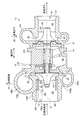
コンプレッサハウジング15Bにおいて、空気取込口33は、回転軸14の延在する軸方向に沿って設けられた給気通路15Baの端部に形成されている。給気通路15Baは、空気取込口33からインペラ31に至り設けられている。また、コンプレッサハウジング15Bにおいて、給気通路15Baに連通しつつインペラ31の外周部に沿って円環形状に形成された圧縮通路15Bbが設けられている。また、コンプレッサハウジング15Bにおいて、図1および図2に示すように、インペラ31における圧縮空気の出口側であって圧縮通路15Bbの外周に連通してディフューザ35の外側に渦巻き形状に形成されたスクロール通路15Bcが設けられている。また、コンプレッサハウジング15Bにおいて、スクロール通路15Bcの一部から接線方向に分岐する排気通路15Bdが設けられている。排気通路15Bdの開口端に圧縮空気吐出口34が形成されている。スクロール通路15Bcは、内径が最も小さい巻き始めから周方向に内径が漸次拡大して形成され周方向に1周して最も拡大された巻き終わりに接続されている。この内形が最も拡大された巻き終わりに排気通路15Bdが分岐して設けられている。このスクロール通路15Bcにおいて排気通路15Bdが分岐した部分は、上述したように巻き始めと巻き終わりとが接続される部分であり、通路の内向きに突出する舌部15Beが形成されている。そして、このような構成のコンプレッサ13では、空気取込口33から給気通路15Baに取り込まれた空気は、インペラ31により圧縮されて圧縮通路15Bbからディフューザ35にて径方向(中心軸Cに直交する方向)外側に拡散されてスクロール通路15Bcを旋回して排気通路15Bdの圧縮空気吐出口34から吐出される。
In the
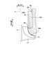
また、コンプレッサハウジング15Bにおいて、図1〜図3に示すように、給気通路15Baに再循環通路15Bfが形成されている。再循環通路15Bfは、給気通路15Baの外側で円環形状に形成された空間である。再循環通路15Bfは、給気通路15Baの内壁面と、給気通路15Baの内壁面に沿って設けられた円環形状の通路壁36との間に設けられた空間であって、軸方向においてインペラ31における給気の入口側で給気通路15Baに開口する環状の抽気溝36aと、空気取込口33側で給気通路15Baに開口する環状の再循環溝36bとを有して給気通路15Baの外側でインペラ31側と空気取込口33側とに通じて形成されている。そして、給気通路15Baの内壁面と通路壁36との間に空間を確保して再循環通路15Bfを形成するため、給気通路15Baの内壁面と通路壁36との間で軸方向に延在し再循環通路15Bfの空間を仕切るストラット36cが周方向に複数設けられている。
Further, in the
このように構成された、排気タービン過給機11は、エンジン(図示せず)から排出された排ガスによりタービン12が駆動し、タービン12の回転が回転軸14に伝達されてコンプレッサ13が駆動し、このコンプレッサ13が燃焼用気体を圧縮してエンジンに供給する。具体的に、エンジンからの排気ガスは、排気ガスの入口通路26を通り、タービンノズル28により静圧膨張され、軸方向の排気ガス流が複数のタービン翼25に導かれることで、複数のタービン翼25が固定されたタービンホイール24によりタービン12が駆動回転する。そして、複数のタービン翼25を駆動した排気ガスは、出口通路27から外部に排出される。一方、タービン12により回転軸14が回転すると、回転軸14で一体のコンプレッサ13のインペラ31が回転し、空気取込口33から給気通路15Baを通って空気が吸入される。吸入された空気は、インペラ31で加圧されて圧縮空気となり、この圧縮空気は、ディフューザ35およびスクロール通路15Bcを通り、圧縮空気吐出口34からエンジンに供給される。また、コンプレッサ13において、インペラ31で加圧された圧縮空気の一部は、抽気溝36aから再循環通路15Bfに抽気されて再循環溝36bから給気通路15Baに戻されて再循環する。このように再循環通路15Bfにて空気を再循環させることで、例えば、エンジンの低回転時において吸入される空気流量が少ない小流量時にインペラ31の圧力比を増大させてコンプレッサ13の作動レンジを拡大する。
In the
上述したコンプレッサ(遠心圧縮機)13において、再循環通路15Bfは、図2に示すように、ストラット36cが周方向に120degごとに3つ設けられている。そして、ストラット36cは、図4に示すように、スクロール通路15Bcに形成された舌部15Beの回転軸14(中心線C)を中心とした角度位置(図4において30degの位置)と、当該舌部15Beの角度位置から120degごとに設けられている。そして、少なくとも1つのストラット36cは、舌部15Beの角度位置において、当該ストラット36cで仕切られた再循環通路15Bfの空間の断面積が抽気溝36aから再循環溝36bに向かって減少して形成されるように配置されている。具体的には、図4に示すように、舌部15Beの角度位置にあるストラット36cに周方向で隣接する150degの角度位置にあるストラット36cにおいて、再循環溝36b側を舌部15Beの角度位置(30degの位置)に向けて傾けて配置されている。
In the compressor (centrifugal compressor) 13 described above, as shown in FIG. 2, the recirculation passages 15Bf are provided with three
また、図には明示しないが、150degの角度位置にあるストラット36cにおいて、再循環溝36b側を舌部15Beの角度位置(30degの位置)に向くように湾曲して形成されていてもよい。また、図には明示しないが、150degの角度位置にあるストラット36cにおいて、舌部15Beの角度位置側の側面のみが再循環溝36b側を舌部15Beの角度位置に向けて傾けたり湾曲したりして形成されていてもよい。また、図には明示しないが、ストラット36cの軸方向の途中から再循環溝36b向けて傾けたり湾曲したりして形成されていてもよい。また、図には明示しないが、舌部15Beの角度位置にあるストラット36cに周方向で隣接する−90degの角度位置にあるストラット36cにおいて、150degの角度位置にあるストラット36cと同様に再循環溝36b側を舌部15Beの角度位置に向けて配置や形成されていてもよい。また、図には明示しないが、舌部15Beの角度位置にあるストラット36cに周方向で隣接する150degの角度位置および−90degの角度位置にある各ストラット36cにおいて、再循環溝36b側を舌部15Beの角度位置に向けて配置や形成されていてもよい。また、舌部15Beの角度位置にストラット36cが一致して設けられていなくてもよく、この場合は舌部15Beの角度位置に最も近い角度位置にあるストラット36cにおいて、再循環溝36b側を舌部15Beの角度位置に向けて配置や形成されていてもよい。
Further, although not explicitly shown in the drawing, the
ところで、コンプレッサ13において、スクロール通路15Bcは、上述したように、内径が最も小さい巻き始めから周方向に内径が漸次拡大して形成され周方向に1周して最も拡大された巻き終わりに接続され、回転軸14に対して非軸対称に構成されている。このため、小流量時では、ディフューザ35の出口の空気の流動にひずみが生じ、舌部15Be付近における静圧が増大する圧力分布が形成される。そのため、ディフューザ35の出口から舌部15Beにかけての逆圧力勾配が増大することとなるため、ケーシングトリートメントによってインペラ31の出口圧力が増大すると、インペラ31の出口での動圧が減少することととなり、逆圧力勾配の急峻な舌部15Be付近で局所的な失速や逆流を生じてしまう。従来のケーシングトリートメントのように再循環通路が回転軸に対して軸対称に構成されている場合、インペラ出口での動圧は周方向に一様に減少するため、舌部付近での半径方向動圧を局所的に増大させ、逆流を抑制することは困難である。
By the way, in the
この点、本実施形態のコンプレッサ13によれば、スクロール通路15Bcから排気通路15Bdが分岐する舌部15Beの回転軸14を中心とした角度位置において、ストラット36cで仕切られた再循環通路15Bfの空間の断面積が抽気溝36aから再循環溝36bに向かって減少して形成されている。このため、図5(a)に示す再循環の流量mの分布のように、再循環通路15Bfで再循環された空気が舌部15Beの角度位置に集められて大流量となる。そして、図5(b)に示すインペラ31出口の流量mの分布のように、インペラ31により圧縮されてディフューザ35を通ってスクロール通路15Bcに排出された空気は、舌部15Beの位置では流量が増大することによって動圧が増大する。この結果、スクロール通路15Bcの舌部15Be付近での局所的な失速や逆流を抑えることができる。しかも、本実施形態のコンプレッサ13によれば、再循環通路15Bfで再循環して排出される空気の流量を変えていることから、図5(c)に示す抽気溝36aの流量mの分布のように、インペラ31における給気の入口側であって再循環通路15Bfに抽気する流量は周方向で一様とすることができ、抽気によるインペラ31の圧力比の上昇を周方向で一様にでき、ある特定の位置で極端に圧力比が増大し半径方向動圧が減少した結果逆流が発生することを抑制できる。
In this regard, according to the
図6は、本実施形態に係る遠心圧縮機の他の例の軸方向断面図である。図7は、本実施形態に係る遠心圧縮機の他の例の周方向断面展開図である。図8は、本実施形態に係る遠心圧縮機の他の例の周方向断面展開図である。図9は、本実施形態に係る遠心圧縮機の他の例の軸方向断面図である。 FIG. 6 is an axial sectional view of another example of the centrifugal compressor according to the present embodiment. FIG. 7 is a circumferential cross-sectional development view of another example of the centrifugal compressor according to the present embodiment. FIG. 8 is a circumferential cross-sectional development view of another example of the centrifugal compressor according to the present embodiment. FIG. 9 is an axial sectional view of another example of the centrifugal compressor according to the present embodiment.
本実施形態のコンプレッサ13の他の例として、図6に示すように、舌部15Beの回転軸14を中心とした角度位置(図4の30degの位置)で、断面積が抽気溝36aから再循環溝36bに向かって減少して形成された空間において径方向の幅が抽気溝36aから再循環溝36bに向かって縮小して形成されていることが好ましい。
As another example of the
図6に示す形態では、再循環通路15Bfの径方向外側の周壁(ハウジング15のコンプレッサハウジング15Bの内壁面)が径方向で狭くなるように再循環溝36bの位置に傾斜面36dが形成されている。図には明示しないが、傾斜面36dは、再循環通路15Bfの通路壁36側に設けられていてもよい。また、図には明示しないが、傾斜面36dは、抽気溝36aから再循環溝36bの全体に亘って設けられていてもよい。
In the form shown in FIG. 6, an
このような構成によれば、ストラット36cで仕切られた空間の径方向の幅が抽気溝36aから再循環溝36bに向かって縮小して形成されていることで、スクロール通路15Bcから排気通路15Bdが分岐する舌部15Beの回転軸14を中心とした角度位置において、ストラット36cで仕切られた再循環通路15Bfの空間の断面積が抽気溝36aから再循環溝36bに向かって減少して形成されている。このため、再循環流の排出側で流速を増加させ、再循環の流量分布を舌部15Beの角度位置で増大させることができるため、上述した効果を顕著に得ることができる。
According to such a configuration, the radial width of the space partitioned by the
さらに、本実施形態のコンプレッサ13の他の例として、図7に示すように、舌部15Beの回転軸14を中心とした角度位置(図6の30degの位置)で、断面積が抽気溝36aから再循環溝36bに向かって減少して形成された空間において抽気溝36aの溝幅の一部が狭く形成されていることが好ましい。
Further, as another example of the
図7に示す形態では、抽気溝36aの溝幅の一部が狭くなるように抽気溝36aのインペラ31側の溝縁に突起36eが形成されている。図には明示しないが、突起36eは、抽気溝36aの空気取込口33側の溝縁に形成されていてもよい。また、図には明示しないが、突起36eは、複数設けられていてもよい。
In the form shown in FIG. 7, a
排気通路15Bdの圧力が上昇してサージ領域となるような状況においては、再循環流の抽気流量が増加しインペラ31の仕事量が増大するため減速が強くなる傾向となる。この点、本実施形態のように、ストラット36cで仕切られた空間の抽気溝36aの溝幅の一部が狭く形成されていると、排気通路15Bdの圧力が上昇してサージ領域となるような状況において、再循環流の抽気流量を抑えることができるため、インペラ31の仕事量の増大を抑制して減速を弱めることができる。従って、再循環流の抽気流量とインペラ31への再循環流量の周方向分布をそれぞれ個別に制御することができる。
In a situation where the pressure in the exhaust passage 15Bd rises to become a surge region, the bleeding flow rate of the recirculation flow increases and the work load of the
さらに、本実施形態のコンプレッサ13の他の例として、図8および図9に示すように、舌部15Beの回転軸14を中心とした角度位置(図8の30degの位置)で、断面積が抽気溝36aから再循環溝36bに向かって減少して形成された空間において抽気溝36aの溝幅の一部を開閉するシャッタ36fと、排気通路15Bdの圧力に基づいて圧力上昇時にシャッタ36fを閉作動させる一方で圧力下降時にシャッタ36fを開作動させる作動機構37と、を備えることが好ましい。
Further, as another example of the
作動機構37は、ディフューザ35の圧力で作動する空性アクチュエータが適用される。具体的に、作動機構37は、シャッタ36fを開閉作動させる作動部材37aと、当該作動部材37aを駆動する空気圧シリンダ37bと、圧縮通路15Bbと空気圧シリンダ37bとを連通する連通管37cと、を有している。この作動機構37は、排気通路15Bdの圧力が上昇した場合に当該圧力により空気圧シリンダ37bが作動部材37aを駆動してシャッタ36fを閉作動させる。一方、作動機構37は、排気通路15Bdの圧力が下降した場合に空気圧シリンダ37bの作動部材37aの駆動を行わずシャッタ36fを開作動させる。
An empty actuator that operates under the pressure of the
上述したように、排気通路15Bdの圧力が上昇してサージ領域となるような状況においては、再循環流の抽気流量が増加しインペラ31の仕事量が増大するため減速が強くなる傾向となる。この点、本実施形態では、排気通路15Bdの圧力上昇時にシャッタ36fを閉作動させることで、再循環流の抽気流量を抑えることができるため、インペラ31の仕事量の増大を抑制して減速を弱めることができる。一方、小流量時である排気通路15Bdの圧力下降時にシャッタ36fを開作動させることで、図5(c)に示す抽気溝36aの流量分布のように、再循環通路15Bfに抽気する流量は周方向で一様とすることができ、抽気によるインペラ31の仕事量を周方向で一様にすることができる。従って、再循環流の抽気流量とインペラ31への再循環流量の周方向分布をそれぞれ個別に制御すると共に、排気通路15Bdの圧力に応じて再循環流の抽気流量を制御することができる。
As described above, in a situation where the pressure in the exhaust passage 15Bd rises to become a surge region, the bleed flow rate of the recirculation flow increases and the work load of the
また、上述したコンプレッサ13を有する排気タービン過給機11によれば、コンプレッサ13において、作動レンジを拡大しつつ、スクロール通路15Bcの舌部15Be付近での局所的な失速や逆流を抑えることができ、エンジンへの給気効率が向上するため、過給機の高効率化を図ることができる。
Further, according to the
なお、本実施形態は、遠心圧縮機として排気タービン過給機11のコンプレッサ13に適用される構成について説明したが、この限りではない。回転軸にインペラが取り付けられてハウジング内で圧縮する遠心圧縮機に好適に用いることができる。
Although the present embodiment has described the configuration applied to the
11 排気タービン過給機
13 コンプレッサ(遠心圧縮機)
14 回転軸
15 ハウジング
15B コンプレッサハウジング
15Ba 給気通路
15Bb 圧縮通路
15Bc スクロール通路
15Bd 排気通路
15Bf 再循環通路
15Be 舌部
31 インペラ
32 ブレード
33 空気取込口
34 圧縮空気吐出口
35 ディフューザ
36 通路壁
36a 抽気溝
36b 再循環溝
36c ストラット
36d 傾斜面
36e 突起
36f シャッタ
37 作動機構
37a 作動部材
37b 空気圧シリンダ
37c 連通管
11
14 Rotating
Claims (4)
前記回転軸に取り付けられて放射状に複数のブレードを有するインペラと、
前記回転軸の延在する軸方向に沿って設けられて空気取込口から前記インペラに至る給気通路、前記インペラの外周部に沿って円環形状に形成された圧縮通路、前記圧縮通路の外周に連通する渦巻き形状のスクロール通路、および前記スクロール通路の一部から接線方向で分岐する排気通路を有し前記回転軸および前記インペラを収容するハウジングと、
前記ハウジングにおいて前記給気通路の内壁面に沿って円環形状に形成され前記インペラ側で前記給気通路に開口する抽気溝と前記空気取込口側で前記給気通路に開口する再循環溝とを有して再循環通路を形成する通路壁と、
前記再循環通路の内部の空間を円環方向で仕切るように前記給気通路の内壁面と前記通路壁との間で軸方向に沿って延在して設けられた複数のストラットと、
を備え、
前記スクロール通路から前記排気通路が分岐する舌部の前記回転軸を中心とした角度位置において、前記ストラットで仕切られた空間の断面積が前記抽気溝から前記再循環溝に向かって減少して形成され、
前記給気通路の内壁面と前記通路壁との間の径方向の幅が前記抽気溝から前記再循環溝に向かって狭くなるように、前記通路壁または前記通路壁に対向する前記給気通路の内壁面に形成された傾斜面により、断面積が前記抽気溝から前記再循環溝に向かって減少して形成されている遠心圧縮機。 Rotation axis and
An impeller attached to the rotating shaft and having a plurality of blades radially
An air supply passage provided along the extending axial direction of the rotating shaft from the air intake port to the impeller, a compression passage formed in a ring shape along the outer peripheral portion of the impeller, and the compression passage of the compression passage. A spiral-shaped scroll passage communicating with the outer periphery, and a housing having an exhaust passage tangentially branching from a part of the scroll passage and accommodating the rotating shaft and the impeller.
In the housing, an air extraction groove formed in a ring shape along the inner wall surface of the air supply passage and opening to the air supply passage on the impeller side and a recirculation groove opening to the air supply passage on the air intake side. A passage wall that has and forms a recirculation passage,
A plurality of struts provided so as to extend in the axial direction between the inner wall surface of the air supply passage and the passage wall so as to partition the space inside the recirculation passage in the annular direction.
With
At an angle position about the rotation axis of the tongue portion where the exhaust passage branches from the scroll passage, the cross-sectional area of the space partitioned by the struts decreases from the bleeding groove toward the recirculation groove. It is,
The air supply passage facing the passage wall or the passage wall so that the radial width between the inner wall surface of the air supply passage and the passage wall narrows from the bleed groove to the recirculation groove. A centrifugal compressor formed by reducing the cross-sectional area from the bleeding groove toward the recirculation groove due to an inclined surface formed on the inner wall surface of the compressor.
前記回転軸に取り付けられて放射状に複数のブレードを有するインペラと、
前記回転軸の延在する軸方向に沿って設けられて空気取込口から前記インペラに至る給気通路、前記インペラの外周部に沿って円環形状に形成された圧縮通路、前記圧縮通路の外周に連通する渦巻き形状のスクロール通路、および前記スクロール通路の一部から接線方向で分岐する排気通路を有し前記回転軸および前記インペラを収容するハウジングと、
前記ハウジングにおいて前記給気通路の内壁面に沿って円環形状に形成され前記インペラ側で前記給気通路に開口する抽気溝と前記空気取込口側で前記給気通路に開口する再循環溝とを有して再循環通路を形成する通路壁と、
前記再循環通路の内部の空間を円環方向で仕切るように前記給気通路の内壁面と前記通路壁との間で軸方向に沿って延在して設けられた複数のストラットと、
を備え、
前記スクロール通路から前記排気通路が分岐する舌部の前記回転軸を中心とした角度位置において、前記ストラットで仕切られた空間の断面積が前記抽気溝から前記再循環溝に向かって減少して形成され、
断面積が前記抽気溝から前記再循環溝に向かって減少して形成された部分において、前記抽気溝の溝縁に形成された突起により、前記抽気溝の溝幅の一部が狭く形成されている遠心圧縮機。 Rotation axis and
An impeller attached to the rotating shaft and having a plurality of blades radially
An air supply passage provided along the extending axial direction of the rotating shaft from the air intake port to the impeller, a compression passage formed in a ring shape along the outer peripheral portion of the impeller, and the compression passage of the compression passage. A spiral-shaped scroll passage communicating with the outer periphery, and a housing having an exhaust passage tangentially branching from a part of the scroll passage and accommodating the rotating shaft and the impeller.
In the housing, an air extraction groove formed in a ring shape along the inner wall surface of the air supply passage and opening to the air supply passage on the impeller side and a recirculation groove opening to the air supply passage on the air intake side. A passage wall that has and forms a recirculation passage,
A plurality of struts provided so as to extend in the axial direction between the inner wall surface of the air supply passage and the passage wall so as to partition the space inside the recirculation passage in the annular direction.
With
At an angle position about the rotation axis of the tongue portion where the exhaust passage branches from the scroll passage, the cross-sectional area of the space partitioned by the struts decreases from the bleeding groove toward the recirculation groove. It is,
In the portion formed by reducing the cross-sectional area from the bleeding groove toward the recirculation groove, a part of the groove width of the bleeding groove is formed narrow by the protrusion formed on the groove edge of the bleeding groove. Centrifugal compressor.
前記排気通路の圧力に基づいて圧力上昇時に前記シャッタを閉作動させる一方で圧力下降時に前記シャッタを開作動させる作動機構と、
を備える請求項1に記載の遠心圧縮機。 A shutter that opens and closes a part of the groove width of the bleeding groove in a portion formed by reducing the cross-sectional area from the bleeding groove toward the recirculation groove.
An operating mechanism that closes the shutter when the pressure rises and opens the shutter when the pressure drops based on the pressure in the exhaust passage.
The centrifugal compressor according to claim 1.
Priority Applications (1)
| Application Number | Priority Date | Filing Date | Title |
|---|---|---|---|
| JP2017036011A JP6865604B2 (en) | 2017-02-28 | 2017-02-28 | Centrifugal compressor and exhaust turbine supercharger |
Applications Claiming Priority (1)
| Application Number | Priority Date | Filing Date | Title |
|---|---|---|---|
| JP2017036011A JP6865604B2 (en) | 2017-02-28 | 2017-02-28 | Centrifugal compressor and exhaust turbine supercharger |
Publications (3)
| Publication Number | Publication Date |
|---|---|
| JP2018141405A JP2018141405A (en) | 2018-09-13 |
| JP2018141405A5 JP2018141405A5 (en) | 2020-01-23 |
| JP6865604B2 true JP6865604B2 (en) | 2021-04-28 |
Family
ID=63527842
Family Applications (1)
| Application Number | Title | Priority Date | Filing Date |
|---|---|---|---|
| JP2017036011A Active JP6865604B2 (en) | 2017-02-28 | 2017-02-28 | Centrifugal compressor and exhaust turbine supercharger |
Country Status (1)
| Country | Link |
|---|---|
| JP (1) | JP6865604B2 (en) |
Families Citing this family (1)
| Publication number | Priority date | Publication date | Assignee | Title |
|---|---|---|---|---|
| JP7235549B2 (en) * | 2019-03-25 | 2023-03-08 | 株式会社Ihi | centrifugal compressor |
Family Cites Families (3)
| Publication number | Priority date | Publication date | Assignee | Title |
|---|---|---|---|---|
| JP2003106293A (en) * | 2001-09-28 | 2003-04-09 | Mitsubishi Heavy Ind Ltd | Fluid machinery |
| JP5351401B2 (en) * | 2007-09-28 | 2013-11-27 | 三菱重工業株式会社 | Compressor |
| WO2011099417A1 (en) * | 2010-02-09 | 2011-08-18 | 株式会社Ihi | Centrifugal compressor using an asymmetric self-recirculating casing treatment |
-
2017
- 2017-02-28 JP JP2017036011A patent/JP6865604B2/en active Active
Also Published As
| Publication number | Publication date |
|---|---|
| JP2018141405A (en) | 2018-09-13 |
Similar Documents
| Publication | Publication Date | Title |
|---|---|---|
| US4086022A (en) | Gas turbine engine with improved compressor casing for permitting higher air flow and pressure ratios before surge | |
| US7189059B2 (en) | Compressor including an enhanced vaned shroud | |
| KR101290905B1 (en) | Centrifugal compressor | |
| JP4527403B2 (en) | Recirculation structure for turbo compressor | |
| CN104141631B (en) | Turbine stator inner housing with abradable material | |
| EP3564537B1 (en) | Centrifugal compressor and turbocharger | |
| US20120272663A1 (en) | Centrifugal compressor assembly with stator vane row | |
| EP3159504B1 (en) | Radial-inflow type axial turbine and turbocharger | |
| JP6265353B2 (en) | On-off valve device and rotating machine | |
| WO2018181343A1 (en) | Centrifugal compressor | |
| US10753370B2 (en) | Variable diffuser with axially translating end wall for a centrifugal compressor | |
| JP6763804B2 (en) | Centrifugal compressor | |
| JP6865604B2 (en) | Centrifugal compressor and exhaust turbine supercharger | |
| JP2018141451A (en) | Turbine and gas turbine | |
| JP2013224627A (en) | Axial flow fan | |
| US20220372992A1 (en) | Rotating machinery | |
| JP7018932B2 (en) | Compressor scroll shape and turbocharger | |
| JP7161419B2 (en) | Method for manufacturing centrifugal rotating machine, and centrifugal rotating machine | |
| JP6935312B2 (en) | Multi-stage centrifugal compressor | |
| KR102223293B1 (en) | Rotating machine, exhaust member of rotating machine | |
| WO2016157530A1 (en) | Rotor blade and axial flow rotary machine | |
| JP6768172B1 (en) | Centrifugal compressor | |
| JP3380897B2 (en) | Compressor | |
| JP7248113B2 (en) | supercharger | |
| JP7350521B2 (en) | rotating machinery |
Legal Events
| Date | Code | Title | Description |
|---|---|---|---|
| A521 | Written amendment |
Free format text: JAPANESE INTERMEDIATE CODE: A523 Effective date: 20191206 |
|
| A621 | Written request for application examination |
Free format text: JAPANESE INTERMEDIATE CODE: A621 Effective date: 20191206 |
|
| A977 | Report on retrieval |
Free format text: JAPANESE INTERMEDIATE CODE: A971007 Effective date: 20201014 |
|
| A131 | Notification of reasons for refusal |
Free format text: JAPANESE INTERMEDIATE CODE: A131 Effective date: 20201020 |
|
| A521 | Written amendment |
Free format text: JAPANESE INTERMEDIATE CODE: A523 Effective date: 20201127 |
|
| TRDD | Decision of grant or rejection written | ||
| A01 | Written decision to grant a patent or to grant a registration (utility model) |
Free format text: JAPANESE INTERMEDIATE CODE: A01 Effective date: 20210309 |
|
| A61 | First payment of annual fees (during grant procedure) |
Free format text: JAPANESE INTERMEDIATE CODE: A61 Effective date: 20210406 |
|
| R150 | Certificate of patent or registration of utility model |
Ref document number: 6865604 Country of ref document: JP Free format text: JAPANESE INTERMEDIATE CODE: R150 |