JP6864199B2 - Excavator, rotary excavator, excavation method and excavation bit - Google Patents
Excavator, rotary excavator, excavation method and excavation bit Download PDFInfo
- Publication number
- JP6864199B2 JP6864199B2 JP2017252197A JP2017252197A JP6864199B2 JP 6864199 B2 JP6864199 B2 JP 6864199B2 JP 2017252197 A JP2017252197 A JP 2017252197A JP 2017252197 A JP2017252197 A JP 2017252197A JP 6864199 B2 JP6864199 B2 JP 6864199B2
- Authority
- JP
- Japan
- Prior art keywords
- excavation
- striking
- casing
- rotation axis
- driving force
- Prior art date
- Legal status (The legal status is an assumption and is not a legal conclusion. Google has not performed a legal analysis and makes no representation as to the accuracy of the status listed.)
- Active
Links
- 238000009412 basement excavation Methods 0.000 title claims description 478
- 238000000034 method Methods 0.000 title claims description 20
- 238000005553 drilling Methods 0.000 claims description 41
- 230000002093 peripheral effect Effects 0.000 claims description 35
- 239000011435 rock Substances 0.000 description 82
- 230000004048 modification Effects 0.000 description 36
- 238000012986 modification Methods 0.000 description 36
- 239000012530 fluid Substances 0.000 description 19
- 238000003780 insertion Methods 0.000 description 14
- 230000037431 insertion Effects 0.000 description 14
- 238000003860 storage Methods 0.000 description 14
- 230000015572 biosynthetic process Effects 0.000 description 12
- 238000005755 formation reaction Methods 0.000 description 12
- 230000000694 effects Effects 0.000 description 9
- 239000002689 soil Substances 0.000 description 7
- 230000003014 reinforcing effect Effects 0.000 description 5
- 230000033001 locomotion Effects 0.000 description 4
- 238000004519 manufacturing process Methods 0.000 description 4
- 230000009471 action Effects 0.000 description 3
- 238000009826 distribution Methods 0.000 description 3
- 230000029142 excretion Effects 0.000 description 3
- 239000000463 material Substances 0.000 description 3
- 230000004044 response Effects 0.000 description 3
- 239000004576 sand Substances 0.000 description 3
- 230000014509 gene expression Effects 0.000 description 2
- 230000007246 mechanism Effects 0.000 description 2
- 238000003825 pressing Methods 0.000 description 2
- 239000000725 suspension Substances 0.000 description 2
- 238000009423 ventilation Methods 0.000 description 2
- 239000002699 waste material Substances 0.000 description 2
- 230000005540 biological transmission Effects 0.000 description 1
- 239000012141 concentrate Substances 0.000 description 1
- 238000010276 construction Methods 0.000 description 1
- 230000007717 exclusion Effects 0.000 description 1
- 210000000887 face Anatomy 0.000 description 1
- 239000007789 gas Substances 0.000 description 1
- 239000008187 granular material Substances 0.000 description 1
- 210000003128 head Anatomy 0.000 description 1
- 230000003116 impacting effect Effects 0.000 description 1
- 239000007788 liquid Substances 0.000 description 1
- 230000007257 malfunction Effects 0.000 description 1
- 230000000149 penetrating effect Effects 0.000 description 1
- 230000008569 process Effects 0.000 description 1
- 230000009467 reduction Effects 0.000 description 1
- 230000002787 reinforcement Effects 0.000 description 1
- 210000001525 retina Anatomy 0.000 description 1
- 230000001629 suppression Effects 0.000 description 1
- XLYOFNOQVPJJNP-UHFFFAOYSA-N water Substances O XLYOFNOQVPJJNP-UHFFFAOYSA-N 0.000 description 1
Images


Description
本発明は、掘削装置、回転式掘削機、掘削方法および掘削ビットに関する。更に詳しくは、機材の入れ替えを行うことなく軟質層および硬岩系岩盤層あるいは硬岩の転石(以下「硬岩」と総称する)のいずれにも対応可能で、入れ替え作業に要する余計な手間と時間を省略することができ、加えて、硬岩掘削時にも、比較的低騒音かつ低振動で掘削作業を行うことができるものに関する。 The present invention relates to excavators, rotary excavators, excavation methods and excavation bits. More specifically, it is possible to deal with both soft layers and hard rock formations or hard rock boulders (hereinafter collectively referred to as "hard rocks") without replacing equipment, which requires extra effort for replacement work. The present invention relates to a rock that can save time and, in addition, can perform excavation work with relatively low noise and low vibration even when excavating hard rock.
近年、特に都市部の建設工事において、基礎杭の杭打等に伴う掘削作業時に発生する振動および騒音が問題となっており、この問題を解決すべく、本発明者等は、下記特許文献1に記載された回転式掘削機を提案している。図17に、この回転式掘削機の掘削装置を掘削装置9として示す。
In recent years, especially in construction work in urban areas, vibration and noise generated during excavation work associated with pile driving of foundation piles have become a problem, and in order to solve this problem, the present inventors have described the following
掘削装置9は、回転駆動装置(図示省略)によって回転運動を付与されて掘削作業(以下「回転掘削作業」という)を行うものであり、掘削装置9の掘削側端に、掘削装置9の直径よりも小さく、回転中心に配置されるビット(以下「中央ビット」という)と、この中央ビットの周辺に配置されるビット(以下「周辺ビット」という)とからなる複数のビットを有し、ビットが互いに時間をずらして打撃駆動するように構成されている。これにより、掘削穴と略同径の単一のビットを上下動させて地盤を打撃していた従来のダウンザホールハンマと比較して、ビットの打撃のサイクルを速くし、代わりにビットの一回の打撃毎に生じる地盤への衝撃が小さくなるようにして、低振動かつ低騒音での掘削作業を可能としている。
The
ところで、本発明者等が掘削装置9を使用した回転式掘削機の運用を行っていたところ、掘削装置9は、中央ビット91の打撃と周辺ビット92の打撃とが同時に行われる場合があることが判明した。なお、掘削装置9によれば、このような同時打撃が起きたとしても、掘削装置9以前からあるダウンザホールハンマよりも低振動、低騒音での掘削作業が可能であるが、本発明者等は更なる振動、騒音の低減を目指し、掘削装置9を改良した試作機93を製作した。
By the way, when the present inventors have been operating a rotary excavator using the
図18(a)に示す試作機93は、掘削面において、中央ビットを廃止すると共に、周辺ビットについて、打撃面931を掘削装置9の回転軸心方向に拡張した角部933を設け、各周辺ビットの角部933の先端角を回転軸心9Rに位置させ、各角部933を若干の隙間を以て突き合わせるように配置したものである(以下、このような構成の周辺ビットを「掘削ビット930」という)。なお、一般的に、掘削ビットの打撃面には、打撃面に対して凸部となる超硬合金製のチップが複数植設されると共に、各チップは所定間隔で分散配置されており、本試作機の掘削ビット930についても同様にチップ934を植設した構成としている。
In the
しかしながら、本発明者等が回転式掘削機9または試作機93(これらを合わせて、以下「回転式掘削機9等」という)を使用して掘削作業を行った際、土砂あるいは軟岩等からなる軟質層(以下「軟質層」という)からなると予測される地盤の掘削作業を行い、想定外の硬岩に当たった場合、回転式掘削機9等では、打撃力不足で硬岩を破砕できないか、あるいは、硬岩の破砕に時間を要する、または、破砕できずに硬岩の傾斜面等に沿って掘削方向が逸れる、という支障が生じていた。
However, when the present inventors perform excavation work using a
このような場合、いったん回転式掘削機9等を抜き取り、打撃力の大きな単ビット型ダウンザホールハンマと入れ替えて対処し、硬岩の破砕後に再度機材の入れ替えを行って掘削作業を再開していたため、余計な手間と時間が掛かっていた。そして、単ビット型ダウンザホールハンマによる作業中は、大きな振動や騒音が発生していた。
In such a case, the
本発明は、以上の点を鑑みて創案されたものであり、機材の入れ替えを行うことなく軟質層および硬岩のいずれにも対応可能で、入れ替え作業に要する余計な手間と時間を省略することができ、加えて、硬岩掘削時にも、比較的低騒音かつ低振動で掘削作業を行うことができる、掘削装置、回転式掘削機、掘削方法および掘削ビットを提供することを目的とする。 The present invention was devised in view of the above points, and can be applied to both soft layers and hard rocks without exchanging equipment, and the extra labor and time required for the excavation work can be omitted. In addition, it is an object of the present invention to provide an excavator, a rotary excavator, an excavation method and an excavation bit capable of performing excavation work with relatively low noise and low vibration even when excavating hard rock.
上記の目的を達成するために本発明の掘削装置は、軸周方向に回転可能な筒状のケーシングと、ケーシングに格納され、駆動力を供給可能な駆動ユニットと、ケーシングに設けられ、駆動力を受けてケーシングの軸方向に進退動可能な複数の掘削ビットを有し、掘削ビットは、ケーシングの回転軸心の周りに配置されると共に、一以上の掘削ビットの打撃面のケーシングの周縁部に沿う部分に、打撃面から突出する突条打撃部が形成された、掘削ビット群とを備える。 In order to achieve the above object, the excavator of the present invention is provided in a cylindrical casing that can rotate in the axial direction, a drive unit that is housed in the casing and can supply a driving force, and a driving force that is provided in the casing. It has a plurality of excavation bits that can move forward and backward in the axial direction of the casing in response to the excavation bits, which are arranged around the axis of rotation of the casing and the peripheral edge of the casing on the striking surface of one or more excavation bits. A digging bit group in which a ridge striking portion protruding from the striking surface is formed is provided in a portion along the above.
ここで、本発明の掘削装置は、軸周方向に回転可能な筒状のケーシングを備えるので、内部に駆動ユニットを格納すると共に掘削ビット群を設けることができ、回転力を付与可能な回転駆動装置と組み合わせて使用することができる。これによって、掘削ビット群が周方向に回転しながら被掘削物に打撃力を加えて行う掘削方法を実施することができる。また、この掘削装置は、前述の駆動ユニットを備えるので、掘削ビット群に駆動力を供給し、各掘削ビットが進退動することができる。 Here, since the excavation device of the present invention includes a tubular casing that can rotate in the axial direction, a drive unit can be stored inside and a group of excavation bits can be provided, and a rotational drive that can apply a rotational force. Can be used in combination with the device. This makes it possible to carry out an excavation method in which the excavation bit group rotates in the circumferential direction while applying a striking force to the object to be excavated. Further, since this excavation device includes the above-mentioned drive unit, a driving force can be supplied to the excavation bit group, and each excavation bit can move forward and backward.
更に、この掘削装置は、前述の掘削ビット群を備えるので、駆動ユニットから供給される駆動力を受けて、各掘削ビットがケーシングの軸方向に進退動作をして、打撃面によって被掘削物を打撃することができる。 Further, since this excavation device includes the above-mentioned excavation bit group, each excavation bit moves forward and backward in the axial direction of the casing in response to the driving force supplied from the drive unit, and the object to be excavated is moved by the striking surface. You can hit.
加えて、この掘削ビット群は、ケーシングに設けられ、打撃面から突出する突条打撃部がケーシングの周縁部に沿う部分に形成された複数の掘削ビットが、打撃面がケーシングの回転軸心の周りに配置されると共に、駆動力を受けてケーシングの軸方向に進退動可能に構成されていることによって、掘削対象である被掘削物(以下「被掘削物」という)に対して突条打撃部が最初の打撃を加えることができるので、仮に、被掘削物が掘削穴中の硬岩であっても、この打撃をきっかけとして硬岩を破砕するか、または、最初の打撃で硬岩に亀裂を生じさせ、続く打撃面の他の部分による打撃によって小片に粉砕することができる。 In addition, this excavation bit group is provided in the casing, and a plurality of excavation bits formed in a portion where a ridge striking portion protruding from the striking surface is formed along the peripheral edge of the casing, and the striking surface is the rotation axis of the casing. By being arranged around and being able to move forward and backward in the axial direction of the casing by receiving driving force, it hits the excavated object to be excavated (hereinafter referred to as "excavated object"). Since the part can make the first impact, even if the object to be excavated is the hard rock in the excavation hole, this impact will trigger the crushing of the hard rock, or the first impact will make the hard rock. It can be cracked and crushed into small pieces by subsequent striking by other parts of the striking surface.
例えば、前述の通り、回転式掘削機9等を使用して、軟質層からなると予測される地盤の掘削作業を行い、想定外の硬岩に当たった場合、回転式掘削機9等では、打撃力不足で硬岩を破砕できないか、あるいは、硬岩の破砕に時間を要する、または、破砕できずに硬岩の傾斜面等に沿って掘削方向が逸れる、という支障が生じていたが、本発明の掘削装置であれば、前述の突条打撃部によって硬岩に対処可能であるため、機材の入れ替えを行うことなく軟質層および硬岩のいずれにも対応することができ、これによって、機材の入れ替えによる余計な手間と時間を省略することができる。加えて、硬岩掘削時にも、比較的低騒音かつ低振動で掘削作業を行うことができる。
For example, as described above, when a
前述の各掘削ビットは、被掘削側に1つの打撃面を有するものであるが、この打撃面は、1つの平坦面のみからなるもののみならず、例えば、被掘削側となる面が段付きで複数面から構成されるもの、異なる複数の傾斜面を含むもの等の態様であってもよい。また、突条打撃部が形成された掘削ビットは、掘削ビット群を構成する掘削ビットの少なくとも一つ以上であり、掘削ビット群を構成する掘削ビットの全てに突条打撃部が形成された態様についても当然含む。なお、各掘削ビットは、側面にも掘削部分(例えば、穴の内側壁を掘削する部分を有していてもよいが、当該側面の掘削部分は、前述の打撃面には該当しない。 Each of the above-mentioned excavation bits has one striking surface on the excavated side, but the striking surface is not limited to only one flat surface, for example, the surface to be the excavated side is stepped. It may be an embodiment composed of a plurality of surfaces, a configuration including a plurality of different inclined surfaces, or the like. Further, the excavation bit on which the ridge striking portion is formed is at least one or more of the excavation bits constituting the excavation bit group, and the ridge striking portion is formed on all the excavation bits constituting the excavation bit group. Of course, it also includes. Each excavation bit may also have an excavation portion (for example, a portion for excavating the inner side wall of the hole) on the side surface, but the excavation portion on the side surface does not correspond to the above-mentioned striking surface.
また、駆動ユニットが、掘削ビット毎に相違する駆動力を付与する態様、または、一部の掘削ビットに付与する駆動力が、他の掘削ビットに付与される駆動力よりも大きくなるようにした態様、のいずれかの態様に設定されている場合は、全ての掘削ビットに付与される打撃力が均一ではなく、打撃力に差を付けることができる。これにより、例えば、回転掘削作業時に硬岩に当たった場合、他の掘削ビットよりも大きな打撃力が付与された掘削ビットが、硬岩を破砕するか、または、最初の打撃で硬岩に亀裂を生じさせ、続く他の掘削ビットの打撃によって小片に粉砕することができる。 Further, the mode in which the drive unit applies a different driving force to each excavation bit, or the driving force applied to some excavation bits is made larger than the driving force applied to other excavation bits. When set to any of the modes, the striking force applied to all the excavation bits is not uniform, and the striking force can be different. As a result, for example, when a hard rock is hit during a rotary excavation work, the excavation bit to which a larger impact force than other excavation bits is applied crushes the hard rock or cracks the hard rock at the first impact. Can be crushed into small pieces by the subsequent impact of other drilling bits.
なお、例えば、掘削ビット群を構成する掘削ビット全ての打撃力を向上させる場合、駆動ユニットの各部品(ピストン等)の大型化等の措置が必要であり、掘削力の向上と引き換えに、装置全体の重量増加または大型化、動力源(作動流体等)の消費量増加といった問題が生じるが、本発明は、少なくとも、掘削ビット群を構成する掘削ビットのいずれか1つについて打撃力を向上させる構成であるため、装置全体の重量増加、駆動流体の消費量増加を必要最小限に抑えることもできる。 For example, in order to improve the striking force of all the excavation bits constituting the excavation bit group, it is necessary to take measures such as increasing the size of each part (piston, etc.) of the drive unit. Although problems such as an increase in overall weight or size and an increase in consumption of a power source (working fluid, etc.) occur, the present invention improves the striking force of at least one of the excavation bits constituting the excavation bit group. Because of the configuration, it is possible to minimize the increase in the weight of the entire device and the increase in the consumption of the driving fluid.
掘削ビット群が、打撃面の1つのみが回転軸心と重複して配置された第1配置態様、または、打撃面の回転軸心側に角部が形成され、回転軸心を挟んで対向配置された一組の打撃面の回転軸心側の縁部のみが回転軸心と重複し、かつ、角部の先端が回転軸心と重複しないように配置された第2配置態様、のいずれかによって、各打撃面の回転軸心側の縁部が回転軸心の近傍で近接するように集合させた構成である場合は、各掘削ビットが回転軸心とその近傍において殆ど隙間を空けずに取り付けられる。この掘削ビット群の構成によれば、掘削ビット群が打撃する被掘削物をムラ無く掘削することができ、硬岩掘削時において掘削した穴(以下「掘削穴」という)の奥側中央に凸状の掘り残し部分(以下「中央凸部」という)が形成されることなく略平坦なものとなる。 The excavation bit group is arranged in the first arrangement mode in which only one of the striking surfaces overlaps the rotation axis, or a corner portion is formed on the rotation axis side of the striking surface and faces each other with the rotation axis in between. Any of the second arrangement modes in which only the edge portion of the arranged set of striking surfaces on the rotation axis side overlaps with the rotation axis and the tip of the corner portion does not overlap with the rotation axis. Therefore, when the edges of each striking surface on the rotation axis side are assembled so as to be close to each other in the vicinity of the rotation axis, each excavation bit has almost no gap between the rotation axis and its vicinity. Attached to. According to the configuration of this excavation bit group, the object to be excavated hit by the excavation bit group can be excavated evenly, and it is convex to the center of the back side of the hole excavated during hard rock excavation (hereinafter referred to as "excavation hole"). It becomes substantially flat without forming an uncut portion (hereinafter referred to as "central convex portion").
図18を参照し、詳しく説明する。過去、本発明者等が前述の試作機93を用いて掘削作業を行った際、土中の硬岩に偶然当たり、作業後に試作機93を引き抜いたところ、掘削穴H1の奥側中央に中央凸部H6が形成されており(図18(c)参照)、更に、各掘削ビット930の角部933近傍が摩滅すると共に、打撃面931自体も凹んだ状態の中央変形部H7が発生していた(図18(b)参照)。後日、硬岩に対する掘削作業を再試行したところ、やはり、中央凸部H6の形成と、試作機93の中央変形部H7の発生が確認された。
This will be described in detail with reference to FIG. In the past, when the present inventors performed excavation work using the above-mentioned
前述の中央凸部H6形成と中央変形部H7発生の原因は必ずしも明らかではないが、以下のような理由によるのではないかと推察される。
(a)試作機93の稼働時において、掘削装置9の掘削側端に配置された掘削ビット930の各々は、個別に異なるタイミングで進退動作をする。つまり、退入状態と進出状態の各掘削ビット930が混在しており、その結果、各掘削ビット930に加わる荷重(自重による軸荷重、打撃による衝撃荷重)は、等分布せずに、進出状態の掘削ビット930に集中することになり、
(b)また、進出状態の掘削ビット930の打撃面931の縁、あるいは縁に近い部分が、平坦な他の部分より擦り減りやすく、特に角部933は先細りになっているので、先端に行くほど強度が弱い。加えて、角部とその近傍は、先細りになって他の部分よりも面積が狭いため、チップ934を他の部分と同様の密度で配置すると、植設可能なチップ934の数が少なく、
(c)前述の通り、進出状態の掘削ビット930に荷重が集中し、更に、進出状態の掘削ビット930のなかでも角部933に荷重が集中しやすいことを鑑みると、角部933に植設された少数のチップ934には、他の部分のチップより大きな負荷が加わり、これによって、他の部分よりも早い段階でチップ934が摩滅するか、あるいはチップ934の脱落といった破損が生じ、
(d)チップ934の破損で角部933近傍の掘削力が著しく低下したことで、打撃面931の他の部分との掘削力に差が生じると共に、チップ934よりも強度が劣るベース部分で直接掘削する状態になって、角部933とその近傍はベース部分ごと摩損または塑性変形して更に掘削力が低下し、
(e)この結果、打撃面931の中で回転軸心9R近傍とその他の部分の掘削力の違いから、掘削穴H1の穴底面H3において外周よりも中央部が盛り上がった形状の中央凸部H6が形成され、
(f)更に、掘削作業中の試作機93の被掘削物側端には、自機の重量あるいは機外からの荷重による強い押圧力が生じており、この押圧状態下で、中央凸部H6に対し、前述の角部933近傍の打撃面931が当たりながら試作機93が回転し続けたことで、塑性変形あるいは偏摩耗が起き、打撃面931に中央変形部H7が発生した、と考えられる。
The cause of the formation of the central convex portion H6 and the occurrence of the central deformed portion H7 is not always clear, but it is presumed that the cause is as follows.
(A) When the
(B) Further, the edge of the
(C) As described above, considering that the load is concentrated on the
(D) Since the excavation force near the
(E) As a result, due to the difference in excavation force between the vicinity of the
(F) Further, a strong pressing force is generated at the end of the
しかしながら、本発明の掘削装置によれば、掘削ビット群が、前述の第1配置態様または第2配置態様のいずれかによって、各打撃面の回転軸心側の縁部が回転軸心の近傍で近接するように集合させた構成であることによって、硬岩に対しても低振動、低騒音での掘削作業が可能であると共に、掘削穴の奥側中央における中央凸部形成を抑制することができ、この中央凸部の形成に伴って生じる掘削ビットの変形や偏摩耗を抑制する(以下「中央変形部発生抑制」という場合がある)ことができる。 However, according to the excavation apparatus of the present invention, the excavation bit group has an edge on the rotation axis side of each striking surface in the vicinity of the rotation axis according to either the first arrangement mode or the second arrangement mode described above. By arranging them so that they are close to each other, it is possible to perform excavation work with low vibration and low noise even for hard rock, and it is possible to suppress the formation of a central convex part in the center of the back side of the excavation hole. It is possible to suppress the deformation and uneven wear of the excavation bit caused by the formation of the central convex portion (hereinafter, may be referred to as "suppression of the occurrence of the central deformed portion").
即ち、掘削ビット群が第1配置態様で構成されている場合、打撃面の1つのみが回転軸心と重複して配置(以下「回転軸心重複配置」という)されるので、打撃面が回転軸心とその近傍に常時重複した状態にすることができる。この回転軸心重複配置によれば、回転掘削作業時に、前述の打撃面の一部が回転軸心とその近傍に確実に常時重複し通過する状態で掘削されるので、被掘削面の中央を常時掘削できると共に、角部への負荷集中が緩和される。この結果、硬岩掘削時においても中央凸部形成が抑制され、これに伴って中央変形部の発生も抑制される。 That is, when the excavation bit group is configured in the first arrangement mode, only one of the striking surfaces is arranged so as to overlap the rotation axis (hereinafter referred to as "rotation axis overlapping arrangement"), so that the striking surface is arranged. It is possible to always overlap the rotation axis and its vicinity. According to this rotation axis overlapping arrangement, during the rotary excavation work, a part of the above-mentioned striking surface is excavated in a state where it always overlaps and passes through the rotary axis and its vicinity, so that the center of the excavated surface is excavated. It can be excavated at all times and the load concentration on the corners is eased. As a result, the formation of the central convex portion is suppressed even during the excavation of hard rock, and the occurrence of the central deformed portion is also suppressed accordingly.
そして、掘削ビット群が第2配置態様で構成されている場合、打撃面の回転軸心側に角部が形成され、回転軸心を挟んで対向配置された一組の打撃面の回転軸心側の縁部のみが回転軸心と重複し、かつ、角部の先端が回転軸心と重複しないように配置されるので、回転掘削作業時に、掘削ビットの角部先端が回転軸心と重複しない配置(以下「打撃面への回転軸心非重複配置」という)となって、角部先端ではなく、長尺な縁部を、回転軸心とその近傍を断続的または略連続的に通過させることができる。これにより、被掘削面の中央を、対向配置された一組の打撃面の回転軸心側の縁部とこれに沿う部分の打撃面で掘削することになり、打撃面に集中する負荷を複数(少なくとも2つ)の打撃面で分散させることができると共に、角部への負荷集中も緩和され、この結果、硬岩掘削時においても中央凸部形成が抑制され、これに伴って中央変形部の発生が抑制される。 When the excavation bit group is configured in the second arrangement mode, a corner portion is formed on the rotation axis side of the striking surface, and the rotation axis of a set of striking surfaces arranged opposite to each other with the rotation axis in between. Since only the side edge overlaps with the rotation axis and the tip of the corner does not overlap with the rotation axis, the tip of the corner of the excavation bit overlaps with the rotation axis during rotary excavation work. No arrangement (hereinafter referred to as "non-overlapping arrangement of the rotation axis on the striking surface"), passing the long edge instead of the tip of the corner intermittently or substantially continuously through the rotation axis and its vicinity. Can be made to. As a result, the center of the surface to be excavated is excavated at the edge of the pair of striking surfaces arranged opposite to each other on the rotation axis side and the striking surface along the same, and a plurality of loads concentrated on the striking surface are applied. It can be dispersed on (at least two) striking surfaces, and the load concentration on the corners is also relaxed. As a result, the formation of the central convex part is suppressed even during hard rock excavation, and the central deformed part is accompanied by this. Is suppressed.
また、駆動ユニットが、第1配置態様において、打撃面が回転軸心と重複して配置された掘削ビット、または、第2配置態様において、打撃面が回転軸心側縁部のみ回転軸心と重複して配置された掘削ビットのいずれかに対し、掘削ビット群を構成する各掘削ビット中で最大の打撃力を付与するように設定されている場合には、回転軸心に重複して配置された掘削ビットの打撃力が特に強化される。例えば、回転掘削作業時に硬岩に当たった場合、最大の打撃力が付与された掘削ビットが硬岩を破砕するか、または、最初の打撃で硬岩に亀裂を生じさせ、続く他の掘削ビットの打撃によって小片に粉砕することができ、これによって、硬岩掘削時における中央凸部の形成抑止および中央変形部の発生抑制の各効果を更に高めることができる。 Further, in the first arrangement mode, the drive unit is an excavation bit in which the striking surface overlaps the rotation axis, or in the second arrangement mode, the striking surface is the rotation axis only at the side edge of the rotation axis. If any of the excavation bits arranged in an overlapping manner is set to give the maximum striking force among the excavation bits constituting the excavation bit group, the excavation bits are arranged overlapping in the rotation axis. The striking force of the drilled bit is especially enhanced. For example, if a hard rock is hit during a rotary excavation operation, the drilling bit with the maximum impact force will either crush the hard rock or crack the hard rock with the first impact, followed by another drilling bit. It can be crushed into small pieces by the impact of the above, which can further enhance the effects of suppressing the formation of the central convex portion and suppressing the generation of the central deformed portion during hard rock excavation.
なお、前述の駆動ユニットが掘削ビット毎に相違する駆動力を付与する態様等と同様に、本発明も、少なくとも、掘削ビット群を構成する掘削ビットのいずれか1つについて打撃力を向上させる構成であるため、装置全体の重量増加、駆動流体の消費量増加を必要最小限に抑えることもできる。 Similar to the above-described mode in which the drive unit applies a different driving force to each excavation bit, the present invention also has a configuration for improving the striking force for at least one of the excavation bits constituting the excavation bit group. Therefore, the increase in the weight of the entire device and the increase in the consumption of the driving fluid can be suppressed to the minimum necessary.
また、駆動ユニットが作動流体により作動する構造であり、ケーシングの被掘削物側とは反対側に接続された作動流体を貯留可能な貯留タンクを備える場合には、外部から導入した作動流体を一時貯留して駆動ユニットに供給することができ、例えば、作動流体が圧縮空気(以下「エア」という)の場合、エアを高圧状態で一時貯留することもできる。 Further, when the drive unit has a structure in which the working fluid is operated and a storage tank capable of storing the working fluid connected to the side opposite to the object to be excavated side of the casing is provided, the working fluid introduced from the outside is temporarily stored. It can be stored and supplied to the drive unit. For example, when the working fluid is compressed air (hereinafter referred to as "air"), the air can be temporarily stored in a high pressure state.
また、貯留タンクが、駆動ユニットによる掘削ビットへの駆動力供給のタイミングが各々相違するように作動流体を適宜分配する作動流体分配部を有する場合は、この作動流体分配部によって駆動ユニットへの作動流体の供給タイミングに変化をつけることができ、例えば、駆動ユニットがピストンを内蔵する複数のピストン部材からなるものである場合、ピストン部材毎の作動タイミングを変化させることができる。 Further, when the storage tank has a working fluid distribution unit that appropriately distributes the working fluid so that the timing of supplying the driving force to the excavation bit by the driving unit is different, the working fluid distribution unit operates the working fluid to the driving unit. The fluid supply timing can be changed. For example, when the drive unit is composed of a plurality of piston members having a built-in piston, the operation timing of each piston member can be changed.
上記の目的を達成するために本発明の回転式掘削機は、軸周方向に回転可能な筒状のケーシング、ケーシングに格納され、駆動力を供給可能な駆動ユニット、および、ケーシングに設けられ、駆動力を受けてケーシングの軸方向に進退動可能な複数の掘削ビットを含み、掘削ビットは、ケーシングの回転軸心の周りに配置されると共に、一以上の掘削ビットの打撃面のケーシングの周縁部に沿う部分に、打撃面から突出する突条打撃部が形成された、掘削ビット群を有する掘削装置と、掘削装置に回転力を付与する回転駆動装置とを備える。 In order to achieve the above object, the rotary excavator of the present invention is provided in a cylindrical casing that can rotate in the axial direction, a drive unit that is housed in the casing and can supply a driving force, and a casing. It contains a plurality of drilling bits that can move forward and backward in the axial direction of the casing under a driving force, and the drilling bits are arranged around the rotation axis of the casing and the peripheral edge of the casing on the striking surface of one or more drilling bits. An excavation device having an excavation bit group in which a ridge striking portion projecting from the striking surface is formed in a portion along the portion, and a rotation driving device for applying a rotational force to the excavation device are provided.
ここで、本発明の回転式掘削機は、掘削装置が軸周方向に回転可能な筒状のケーシングを有するので、内部に駆動ユニットを格納すると共に掘削ビット群を設けることができ、回転駆動装置と組み合わせて回転力が付与される。これによって、掘削ビット群が周方向に回転しながら被掘削物に打撃力を加えて行う掘削方法を実施することができる。 Here, in the rotary excavator of the present invention, since the excavator has a cylindrical casing that can rotate in the axial direction, a drive unit can be stored inside and an excavation bit group can be provided, and the rotary drive device can be provided. In combination with, rotational force is given. This makes it possible to carry out an excavation method in which the excavation bit group rotates in the circumferential direction while applying a striking force to the object to be excavated.
更に、本発明の回転式掘削機は、掘削装置が前述の駆動ユニットを有するので、掘削ビット群に駆動力を供給し、各掘削ビットが進退動することができる。加えて、掘削装置が前述の掘削ビット群を有するので、駆動ユニットから供給される駆動力を受けて、各掘削ビットがケーシングの軸方向に進退動作をして、打撃面によって被掘削物を打撃することができる。 Further, in the rotary excavator of the present invention, since the excavator has the above-mentioned drive unit, a driving force can be supplied to the excavation bit group, and each excavation bit can move forward and backward. In addition, since the excavator has the above-mentioned excavation bit group, each excavation bit moves forward and backward in the axial direction of the casing in response to the driving force supplied from the drive unit, and hits the object to be excavated by the striking surface. can do.
加えて、本発明の回転式掘削機は、掘削装置が前述の構成による掘削ビット群を有することによって、被掘削物に対して突条打撃部が最初の打撃を加えることができるので、仮に、被掘削物が掘削穴中の硬岩であっても、この打撃をきっかけとして硬岩を破砕するか、または、最初の打撃で硬岩に亀裂を生じさせ、続く打撃面の他の部分による打撃によって小片に粉砕することができる。 In addition, in the rotary excavator of the present invention, since the excavator has the excavation bit group having the above-described configuration, the ridge striking portion can make the first impact on the object to be excavated. Even if the object to be excavated is hard rock in the excavation hole, this blow will trigger the crushing of the hard rock, or the first blow will cause a crack in the hard rock, followed by another part of the hitting surface. Can be crushed into small pieces.
更に、本発明の回転式掘削機は、前述の回転駆動装置を備えるので、回転駆動装置と組み合わせて掘削装置を回転させることができ、これによって、掘削ビット群が周方向に回転しながら被掘削物に打撃力を加えて行う掘削方法を実施することができる。 Further, since the rotary excavator of the present invention includes the above-mentioned rotary drive device, the excavator can be rotated in combination with the rotary drive device, whereby the excavation bit group is rotated in the circumferential direction to be excavated. It is possible to carry out an excavation method in which a striking force is applied to an object.
そして、本発明の回転式掘削機によれば、前述の回転式掘削機9等を使用した場合と比較して、突条打撃部によって硬岩に対処可能であるため、機材の入れ替えを行うことなく軟質層および硬岩のいずれにも対応することができ、これによって、機材の入れ替えによる余計な手間と時間を省略することができる。加えて、硬岩掘削時にも、比較的低騒音かつ低振動で掘削作業を行うことができる。
Then, according to the rotary excavator of the present invention, since it is possible to deal with hard rock by the ridge striking portion as compared with the case where the above-mentioned
上記の目的を達成するために本発明の掘削方法は、ケーシング、ケーシングに格納された駆動ユニット、および、ケーシングに設けられ、駆動ユニットからの駆動力を受けてケーシングの軸方向に進退動可能な複数の掘削ビットを有し、掘削ビットは、ケーシングの回転軸心の周りに配置されると共に、一以上の掘削ビットの打撃面のケーシングの周縁部に沿う部分に、打撃面から突出する突条打撃部が形成された、掘削ビット群を有する掘削装置と、掘削装置に回転力を付与可能な回転駆動装置とからなる回転式掘削機を組み立て、被掘削物上に設置する第1工程と、第1工程により設置された回転駆動装置によって掘削装置を回転させながら、掘削装置の掘削ビットを進退させ、打撃面によって被掘削物を打撃することで被掘削物を掘削する第2工程とを備える。 In order to achieve the above object, the excavation method of the present invention is provided in the casing, the drive unit housed in the casing, and the casing, and can move forward and backward in the axial direction of the casing by receiving the driving force from the drive unit. It has a plurality of excavation bits, the excavation bits are arranged around the axis of rotation of the casing, and a protrusion protruding from the striking surface along the peripheral edge of the casing of the striking surface of one or more excavation bits. The first step of assembling a rotary excavator consisting of an excavator having an excavation bit group on which a striking portion is formed and a rotary drive device capable of applying a rotational force to the excavator and installing the excavator on the object to be excavated. It is provided with a second step of excavating the excavated object by moving the excavating bit of the excavating device forward and backward and striking the excavated object with the striking surface while rotating the excavating device by the rotary drive device installed in the first step. ..
ここで、本発明の掘削方法の第1工程によれば、前述の構成の掘削装置および回転駆動装置とからなる回転式掘削機を、地面等の被掘削物に向けて設置することができる。 Here, according to the first step of the excavation method of the present invention, a rotary excavator including the excavator and the rotary drive device having the above-described configuration can be installed toward an object to be excavated such as the ground.
そして、本発明の掘削方法の第2工程によれば、回転式掘削機が回転駆動装置によって掘削装置を回転させることができるものであり、これによって、掘削ビット群が周方向に回転しながら被掘削物に打撃力を加えて行う掘削方法を実施することができる。更に、この第2工程によれば、前述の回転式掘削機9等を使用した場合と比較して、突条打撃部によって硬岩に対処可能であるため、機材の入れ替えを行うことなく軟質層および硬岩のいずれにも対応することができ、これによって、機材の入れ替えによる余計な手間と時間を省略することができる。加えて、硬岩掘削時にも、比較的低騒音かつ低振動で掘削作業を行うことができる。
Then, according to the second step of the excavation method of the present invention, the rotary excavator can rotate the excavator by the rotary drive device, whereby the excavation bit group is covered while rotating in the circumferential direction. It is possible to carry out an excavation method in which a striking force is applied to an excavated object. Further, according to this second step, since it is possible to deal with hard rock by the ridge striking portion as compared with the case where the above-mentioned
上記の目的を達成するために本発明の掘削ビットは、掘削装置のケーシングに取り付け可能で、ケーシングに格納された駆動ユニットから供給される駆動力を受ける接続軸部と、接続軸部とは反対側に打撃面が設けられ、掘削装置への取着状態で、ケーシングの周縁部に沿う部分に、打撃面から突出する突条打撃部が形成されたヘッド部とを備える。 In order to achieve the above object, the excavation bit of the present invention can be attached to the casing of the excavator, and the connection shaft portion that receives the driving force supplied from the drive unit stored in the casing is opposite to the connection shaft portion. A striking surface is provided on the side, and a head portion having a ridge striking portion protruding from the striking surface is provided in a portion along the peripheral edge portion of the casing in a state of being attached to the excavator.
ここで、本発明の掘削ビットは、前述の接続軸部を備えることによって、掘削装置の駆動ユニットから供給される駆動力を受けると共に、接続軸部を介してヘッド部へ駆動力を供給することができる。更に、本発明の掘削ビットは、前述のヘッド部を備えることによって、接続軸部とは反対側に設けられた打撃面で被掘削物を打撃し、被掘削物を掘削することができる。 Here, the excavation bit of the present invention receives the driving force supplied from the driving unit of the excavating device by providing the above-mentioned connecting shaft portion, and also supplies the driving force to the head portion via the connecting shaft portion. Can be done. Further, the excavation bit of the present invention can excavate the excavated object by striking the excavated object with the striking surface provided on the side opposite to the connecting shaft portion by providing the above-mentioned head portion.
そして、この掘削ビットは、駆動力を受けて接続軸部の軸方向に進退動作し、被掘削物に対して突条打撃部が最初の打撃を加えることができるので、仮に、被掘削物が掘削穴中の硬岩であっても、この打撃をきっかけとして硬岩を破砕するか、または、最初の打撃で硬岩に亀裂を生じさせ、続く打撃面の他の部分による打撃によって小片に粉砕することができる。 Then, this excavation bit receives a driving force and moves back and forth in the axial direction of the connecting shaft portion, and the ridge striking portion can give the first impact to the excavated object. Even the hard rock in the excavation hole is crushed by this impact, or the hard rock is cracked by the first impact and then crushed into small pieces by the impact by other parts of the impact surface. can do.
このように、本発明の掘削ビットによれば、前述の掘削装置、回転式掘削機の掘削装置、および、掘削方法で使用される掘削装置に複数を取り付けることで、複数の打撃面からなる掘削ビット群となり、同掘削ビットを取着した掘削装置等によって掘削作業を行う際に、被掘削物に対して突条打撃部が最初の打撃を加えることができるので、仮に、被掘削物が掘削穴中の硬岩であっても、この打撃をきっかけとして硬岩を破砕するか、または、最初の打撃で硬岩に亀裂を生じさせ、続く打撃面の他の部分による打撃によって小片に粉砕することができる。 As described above, according to the excavation bit of the present invention, by attaching a plurality of excavators to the above-mentioned excavator, the excavator of the rotary excavator, and the excavator used in the excavation method, excavation composed of a plurality of striking surfaces When excavation work is performed by a bit group and an excavation device or the like to which the excavation bit is attached, the ridge striking part can apply the first impact to the excavated object, so that the excavated object is excavated. Even the hard rock in the hole is crushed by this impact, or the hard rock is cracked by the first impact and then crushed into small pieces by the impact by other parts of the impact surface. be able to.
そして、本発明の掘削ビットによれば、取着される掘削装置を、機材の入れ替えを行うことなく軟質層および硬岩のいずれにも対応可能なものにすることができ、これによって、機材の入れ替えによる余計な手間と時間を省略することができ、加えて、硬岩掘削時にも比較的低騒音かつ低振動で掘削作業を行うことができるものとすることができる。 Then, according to the excavation bit of the present invention, the excavator to be attached can be made compatible with both a soft layer and a hard rock without exchanging the equipment, whereby the equipment can be used. It is possible to omit extra labor and time due to replacement, and in addition, it is possible to perform excavation work with relatively low noise and low vibration even when excavating hard rock.
本発明の掘削装置、回転式掘削機、掘削方法および掘削ビットによれば、機材の入れ替えを行うことなく軟質層および硬岩のいずれにも対応可能で、入れ替え作業に要する余計な手間と時間を省略することができ、加えて、硬岩掘削時にも、比較的低騒音かつ低振動で掘削作業を行うことができる。 According to the excavator, the rotary excavator, the excavation method and the excavation bit of the present invention, it is possible to deal with both soft layers and hard rocks without exchanging the equipment, and the extra labor and time required for the excavation work can be saved. It can be omitted, and in addition, even when excavating hard rock, the excavation work can be performed with relatively low noise and low vibration.
図1ないし図16を参照して、本発明の実施の形態を更に詳細に説明する。なお、以下の説明は、
〔第1実施形態〕(掘削ビット群が第2配置態様である掘削装置2a)、
〔第2実施形態〕(掘削ビット群が第1配置態様である掘削装置2b)、
〔変形例1〕−〔変形例6〕、
の順序により行う。また、図面各図における符号は、煩雑さを軽減し理解を容易にする範囲内で付しており、同一符号が付される複数の同等物についてはその一部にのみ符号を付す場合がある。そして、後述する各実施形態および各変形例においては、作動流体としてエアを採用しているが、これに限定するものではなく、例えば、各種気体、水やオイル等の液体等の他の流体を除外するものではない。
Embodiments of the present invention will be described in more detail with reference to FIGS. 1 to 16. The following explanation is
[First Embodiment] (
[Second Embodiment] (
[Modification 1]-[Modification 6],
It is done in the order of. In addition, the reference numerals in each drawing are attached within a range that reduces complexity and facilitates understanding, and a plurality of equivalents having the same reference numerals may be assigned only a part thereof. .. And, in each embodiment and each modification described later, air is adopted as a working fluid, but the present invention is not limited to this, and for example, various gases, other fluids such as liquids such as water and oil can be used. It is not an exclusion.
〔第1実施形態〕
図1に示す回転式掘削機1は、掘削装置2aと、掘削装置2aに回転運動を付与可能な回転駆動装置8を備える。各部については以下で詳述する。そして、回転式掘削機1を使用して行う掘削方法は、
(第1工程)複数の掘削ビットからなる掘削ビット群5aを有する掘削装置2aと、回転駆動装置8とからなる回転式掘削機1を組み立て、被掘削物H上に設置し、
(第2工程)第1工程で設置された回転駆動装置8によって掘削装置2aを回転させながら、掘削装置2aの各掘削ビットを進退させ、打撃面65dによって被掘削物Hを打撃することで、被掘削物Hを掘削する、
ことにより行われる。
[First Embodiment]
The
(First step) An
(Second step) While rotating the
It is done by.
この掘削方法によれば、回転式掘削機1が回転駆動装置8によって掘削装置2aを回転させ、掘削ビット群5aが周方向に回転しながら被掘削物Hに打撃力を加えて行う掘削方法を実施することができる(図1参照)。更に、この掘削方法によれば、前述の回転式掘削機9等を使用した場合と比較して、突条打撃部655によって硬岩H4に対処可能であるため、機材の入れ替えを行うことなく軟質層H5および硬岩H4のいずれにも対応することができ(図10参照)、これによって、機材の入れ替えによる余計な手間と時間を省略することができる。加えて、硬岩掘削時にも、比較的低騒音かつ低振動で掘削作業を行うことができる。
According to this excavation method, the
(掘削装置2a)
図1〜図10を参照する。掘削装置2aは、ケーシング3、ケーシング3に格納された駆動ユニット4、および、複数の掘削ビット6A1、6A2、6B1、6B2(以下、これら全ての説明の際には「6A1〜6B2」という)で構成された第2配置態様52である掘削ビット群5aを備えている。そして、掘削装置2aでは、エアタンク7(前述の貯留タンクに相当する)が、ケーシング3の掘削ビット群5aとは反対側となる位置に連設されている。
(
See FIGS. 1 to 10. The
<ケーシング3>
ケーシング3は、回転軸心3Rの軸周方向に回転可能に形成され、内部に駆動ユニット4を格納すると共に掘削ビット群5aを設けることができ、組み合わせて使用する回転駆動装置8が掘削装置2aの全体を回転させ、これによって、掘削ビット群5aが周方向3Cに回転しながら被掘削物H(本実施形態では地面)に打撃力を加えて行う掘削方法を実施することができる(図1参照)。
<
The
本実施の形態において、ケーシング3は中空円筒体であり、ケーシング3のエアタンク7側にはエアタンク側蓋体33が、ケーシング3の被掘削物側には被掘削物側蓋体34が、各々着脱可能に取り付けられている。エアタンク側蓋体33および被掘削物側蓋体34は所要の厚みを有し、ピストン部材41の各端部を嵌挿するための挿入穴331、341が各々形成されている(図4、図6参照)。
In the present embodiment, the
エアタンク側蓋体33の挿通穴331は、嵌挿されるピストン部材41の一端側の通気穴(図示省略)と連通している。そして、被掘削物側蓋体34の挿入穴341は、嵌挿されるピストン部材41の他端側の通気穴(符号省略)と連通している(図4、図6参照)。
The
被掘削物側蓋体34の外面(図4では底面)には、着脱可能なチャックガイド35およびドライブチャック36が取り付けられている。なお、掘削ビット群5aは、チャックガイド35およびドライブチャック36を介して、ケーシング3の被掘削側に取り付けられることとなる(図4、図6参照)。
A
チャックガイド35は、ケーシング3にボルト370とナット371からなる締着具を用いて取り付けられている。そして、チャックガイド35は、被掘削側に切欠が形成された平面視略円形状で所定の厚みを有し、掘削ビット6A1〜6B2を嵌挿可能な複数の貫通穴351(掘削ビット6A1〜6B2と対応する数で、本実施形態では合計4つ)が周方向に略等間隔で形成されている(図4、図6参照)。
The
ドライブチャック36は、筒状体であり、チャックガイド35とケーシング3の間に挟まれて取り付けられている。そして、ドライブチャック36は、長手方向一端側が被掘削物側蓋体34の挿入穴341に嵌入し、長手方向他端側がチャックガイド35の貫通穴351に嵌入するように取り付けられる(図4、図6参照)。ドライブチャック36は、少なくとも長手方向他端側近傍の内径が断面視六角形に形成されており(図示省略)、後述する各掘削ビット6A1〜6B2の接続軸部61を嵌挿可能な大きさに設定されている。
The
また、このケーシング3は、その胴部外面31において長手方向中間となる領域に、スクリュー部32が設けられている(図3、図5等参照)。このスクリュー部32によれば、掘削作業の際に発生する粉砕した岩盤や土砂(スライム)を掘削穴の穴口H2に向かって(例えば、竪穴であれば地表方向)へより効率的に送り出すこと(以下「排土」という)ができる(図10(c)参照)。
Further, the
そして、前述のスクリュー部32は、設けられた領域が、胴部外面31の長手方向の両端(図5において上部あるいは下部)よりも径小に設定され、この径小部分に設けられた螺旋羽根321と、この螺旋羽根321と交差すると共に胴部外面31の長手方向に延設された補強リブ322からなる。更に、螺旋羽根321と補強リブ322は、外周方向への突出した先端の位置が前述の胴部外面31の長手方向の両端を結ぶ仮想面3Vと略同じ高さに設定されている。そして、螺旋羽根321には周方向に等間隔で係合凹部324が形成されている。
The area of the
前述のスクリュー部32は、この突出高さに設定されていることにより、掘削作業の際に、掘削穴H1を当初設定値よりも拡張することなく、排土を可能にしている。また、このスクリュー部32は、胴部外面31の上部あるいは下部よりも突出しないので、例えば、掘削装置2aを横臥させて運搬する際に、螺旋羽根321先端が破損するといった事故の発生可能性を抑制できる。更に、このスクリュー部32は、補強リブ322を有しているので、螺旋羽根321の板厚方向から加わる外力による螺旋羽根321の変形事故の発生可能性を抑制できる。
Since the
<駆動ユニット4>
図1、図4および図6を主に参照する。駆動ユニット4は、ケーシング3に格納されており、掘削ビット群5aに駆動力を供給し、各掘削ビット6A1〜6B2を進退動させることができる。
<Drive
FIG. 1, FIG. 4 and FIG. 6 are mainly referred to. The
本実施形態において、駆動ユニット4は、ケーシング3内に格納された4本のピストン部材41により構成される。各ピストン部材41は、ピストン411の他、シリンダー412、チェックバルブ(符号省略)、エアディストリビュータ(符号省略)、バルブスプリング(符号省略)、メイクアップリング(符号省略)、O−リング(符号省略)、ピストンリタイナーリング(符号省略)、ビットリティーナリング(符号省略)等を有する構造であり、公知のダウンザホールハンマの駆動機構(例えば、特開昭61−92288号公報記載)とほぼ同様の構造である。そして、各ピストン部材41は、ケーシング3内において、前述の被掘削物側蓋体34とチャックガイド35によって挟まれた状態で固定されている。
In the present embodiment, the
この駆動ユニット4の作用を簡単に説明する。エアタンク7からピストン部材41に流入したエアは、まず、ピストン411側面を通過して掘削ビット6A1〜6B2側に回り、これにより、ピストン411がエアタンク7側へ移動する。次に、このピストン411の移動に伴ってエアがピストン411のエアタンク7側に回ると共に、後述する掘削ビット6A1〜6B2の接続軸部61の開口部611から打撃面65の開口部653へエアが排出され、これにより、エアタンク7側から掘削ビット6A1〜6B2側へピストン411が移動する。この動作の繰り返しによりピストン411が進退動し、ピストン411が掘削ビット6A1〜6B2側へ移動した際に掘削ビット6へ衝撃力(前述の駆動力に相当する)が加わり、この衝撃力によって掘削ビット6A1〜6B2が駆動する。
The operation of the
また、この駆動ユニット4は、後述するエアタンク7内に設けられたエア流通制御部材73(前述の「作動流体分配部」に相当する)によって、エアEの流入タイミングが調節され、ピストン411が各々異なるタイミングで進退するように設定されている。
Further, in the
更にまた、この駆動ユニット4は、ピストン部材41が各々異径で、内蔵するピストン411の重量が相違するように設定してある(図7参照)。具体的に、本実施形態では、時計回り周方向の順で、後述する一の掘削ビット6A1に連結されるピストン部材41のピストン411は、直径が10インチ(254mm)で重量が46kgであり、この掘削ビット6A1に隣接する一の掘削ビット6B1に連結されるピストン部材41のピストン411は、直径が6インチ(152.4mm)で重量が23kgであり、この掘削ビット6B1に隣接する(即ち一の掘削ビット6A1の対向位置にある)他の掘削ビット6A2に連結されるピストン部材41のピストン411は、直径が8インチ(203.8mm)で重量が31kgであり、この掘削ビット6A2に隣接する(即ち一の掘削ビット6B1の対向位置にある)他の掘削ビット6B2に連結されるピストン部材41のピストン411は、直径が5インチ(127mm)で重量が9.4kgに、設定されている。
Furthermore, the
このように、掘削ビット群5aを構成する掘削ビット6A1〜6B2中で、最大の打撃面(掘削ビット6A1の打撃面65a)に対して最大のピストン411により生じる最大の打撃力が付与されるので、回転掘削作業時に、最大の打撃力が付与された掘削ビット6A1が硬岩H4を破砕するか、または、硬岩H4に亀裂を生じさせ、続く他の掘削ビット6A2、6B1、6B2の打撃によって小片に粉砕することができ、これによって、装置全体の重量増加、作動流体(エア)の消費量増加を必要最小限に抑えつつも、硬岩掘削時における中央凸部H6の形成抑止および中央変形部H7の発生抑制の各効果を更に高めることができる。
In this way, among the excavation bits 6A1 to 6B2 constituting the
<掘削ビット、掘削ビット群>
図5および図7を参照する。掘削ビット群5aは、ケーシング3の被掘削物側に設けられ、駆動力を受けてケーシング3の軸方向に進退動可能な4つの掘削ビット6A1〜6B2で構成され、掘削ビット6A1〜6B2の各打撃面65がケーシング3の回転軸心3Rの周りに配置されている。
<Excavation bit, excavation bit group>
See FIGS. 5 and 7. The
掘削ビット群5aは、ケーシング3に設けられ、打撃面65から打撃方向に突出する突条打撃部655がケーシング3の周縁部に沿う部分に形成された複数の掘削ビット6A1〜6B2が、被掘削物Hに対して突条打撃部655によって、最初の打撃を加えることができるように構成されている。これにより、仮に、被掘削物が掘削穴H1中の硬岩H4であっても、この打撃をきっかけとして硬岩H4を破砕するか、または、最初の打撃で硬岩H4に亀裂を生じさせ、続く打撃面の他の部分による打撃によって小片に粉砕することができる。つまり、軟質層H5のみならず硬岩H4に対処可能であるため、機材の入れ替えを行うことなく軟質層H5および硬岩H4のいずれにも対応することができ、これによって、機材の入れ替えによる余計な手間と時間を省略することができる。加えて、硬岩掘削時にも、比較的低騒音かつ低振動で掘削作業を行うことができる。
The
加えて、掘削ビット群5aは、掘削ビット群5aを構成する掘削ビット6A1〜6B2に、各打撃面65の回転軸心3R側に角部67が形成されている。そして、掘削ビット群5aは、回転軸心3Rを挟んで対向配置された一組の打撃面65(掘削ビット6A1、6A2の打撃面)の回転軸心3R側の縁部661のみが回転軸心3Rと重複し、かつ、角部67の先端が回転軸心3Rと重複しないように配置された第2配置態様51で、各打撃面65の回転軸心3R側の縁部が回転軸心3Rの近傍で近接するように集合させてある(図7参照)。各打撃面65は、ケーシング3の回転軸心3Rの略直交面上6Cにあって(図5参照)、被掘削物Hを打撃することができる。
In addition, in the
この掘削ビット群5aは、掘削ビット6A1〜6B2の各打撃面65がケーシング3の回転軸心3Rの周りに配置され、前述の第2配置態様51によって、各打撃面65の回転軸心3R側の縁部が回転軸心3Rの近傍で近接するように集合させてあるので、各掘削ビット6A1〜6B2が回転軸心3Rとその近傍において殆ど隙間を空けずに取り付けられる。この掘削ビット群5aの構成によれば、掘削ビット群5aが打撃する被掘削物Hをムラ無く掘削することができ、掘削作業によって形成された掘削穴H1は、内底に中央凸部が形成されることなく略平坦なものとなる。
In the
そして、掘削ビット群5aは、第2配置態様51で構成されているので、回転掘削作業時に、回転軸心方向視で、打撃面65への回転軸心非重複配置となって、角部67先端よりも長尺な縁部611が回転軸心3Rとその近傍を断続的または略連続的に通過させることができる。これにより、被掘削面の中央を対向配置された掘削ビット6A1、6A2の打撃面65の回転軸心側の回転軸心側の縁部661とこれに沿う部分の打撃面65で掘削することになり、打撃面65に集中する負荷を複数(本実施形態では2つ)の打撃面65で分散させることができると共に、角部67への負荷集中も緩和され、この結果、硬岩掘削時においても中央凸部H6形成が抑制され、これに伴って中央変形部H7の発生も抑制される。
Since the
詳しくは、この掘削ビット群5aは、同一形状の一組(2つ)の掘削ビット6A1、6A2と、同一形状の一組(2つ)の掘削ビット6B1、6B2(合計4つ)を十字状に組み合わせて構成されている。ここで、掘削ビット6A1、6A2は、回転軸心3Rを挟んで対向配置されると共に、掘削ビット6B1、6B2は、周方向において掘削ビット6A1、6A2の間となる箇所に、回転軸心3Rを挟んで対向配置されている。
Specifically, in this
そして、掘削ビット6A1、6A2と掘削ビット6B1、6B2は、後述するように打撃面等の形状および大きさが相違しており(掘削ビット6A1、6A2よりも掘削ビット6B1、6B2の方が小さく設定されている)、これによって、回転軸心方向視で、第2配置態様51は、掘削ビット6A1、6A2の辺部66のみが回転軸心3Rに近接配置されると共に、掘削ビット6B1、6B2は、辺部66および角部67のいずれもが回転軸心3Rに近接配置されない(換言すると、回転軸心3Rから離隔配置される)構成となっている。更に、掘削ビット6A1、6A2と掘削ビット6B1、6B2の角部67は、ケーシング3の回転軸心3Rを基準として、回転軸心3Rからケーシング3の外周端までの距離の約6%となる箇所に配置されている。
The excavation bits 6A1 and 6A2 and the excavation bits 6B1 and 6B2 are different in shape and size of the striking surface and the like as described later (the excavation bits 6B1 and 6B2 are set smaller than the excavation bits 6A1 and 6A2). As a result, in the
図8、図10を参照する。本実施形態における掘削ビット6A1(6A2も同形状)は、駆動ユニット4から供給される駆動力を受ける接続軸部61と、接続軸部61とは反対側に打撃面65が設けられ、各辺部66で囲まれた打撃面65が、掘削装置2aへの取着状態で回転軸心3R側となる箇所に角部67を有し、かつ、角部67を挟む両縁が異なる長さに設定されており、取着状態で角部67の先端が回転軸心3Rと重複しないように構成されたヘッド部62とを備える(図8参照)。そして、掘削ビット6A1内には、接続軸部61の開口部611から打撃面65の開口部653に至るエアの流路621が形成されている(図10参照)。
See FIGS. 8 and 10. The excavation bit 6A1 (same shape as 6A2) in the present embodiment is provided with a connecting
この接続軸部61は、ピストン411への連結手段であり、筒状で先端に開口部611が形成された自由端であると共に、基端がヘッド部62に接合され、前述のドライブチャック36内に嵌挿可能な外径に形成されている。加えて、接続軸部61は、外周面の軸線方向中間からヘッド部62側の領域が、断面視六角形に形成されており、ドライブチャック36への嵌挿時において、当該部分はスプライン軸としての機能を発揮すると共に、周方向への回転を防止し、進退方向への進退動作をガイドすることができる。また、接続軸部61における前述のエアの流路621には、ヘッド部62方向に流通するエアの逆流を防止可能な逆止弁(図示省略)を設けてある。なお、接続軸部61は、前述したハンマビットリティーナリングとOリングにより、ドライブチャック側から外れないように装着される。
The
掘削ビット6A1のヘッド部62は、略五角柱状であり、接続軸部61の基端と接合する接合部622、接合部622と接続し接続軸部61の反対側に向かって延設された第1側壁面623a、第2側壁面623b、第3側壁面623c、第4側壁面623dおよび第5側壁面623e(以下、これら全ての説明の際には「623a〜e」という)、側壁部623a〜eと接続し面形状が略五角形である打撃面65により構成されている。そして、掘削ビット6A1は、打撃面65全域と側壁部623の一部(後述する第1側壁面623aの打撃面寄りの箇所のみ)に、ボタン状の超硬合金製のチップ651が所定間隔で植設(分散配置)されている。
The
掘削ビット6A1は、チャックガイド35への取着状態(以下、本段落中で単に「取着状態」という)においてケーシング3の胴部外面31の一部に沿う形状で配置される端面視円弧状の第1側壁面623aと、第1側壁面623aの一の側縁(「側縁」とは接合部622側と打撃面65側を除く意味で使用し、本段落中で以下同じ)と接続し、取着状態においてケーシング3の回転軸心3R側(以下、本段落中で単に「回転軸心側」という)に向かって延設された第2側壁面623bと、第1側壁面623aの他の側縁と接続し、取着状態において回転軸心3R側に向かって延設された第3側壁面623cと、第2側壁面623bの第1側壁面623aと反対側縁と接続し、回転軸心3R側かつヘッド部62の水平長軸方向に向けて延設された第4側壁面623dと、第3側壁面623cの第1側壁面623aと反対側端と接続し、ケーシング3の回転軸心3R側かつヘッド部62の水平長軸方向に向けて延設されて第4側壁面623dの第2側壁面623bと反対側端に接続して鋭角な角部67を構成すると共に、第4側壁面623dよりも水平長軸方向に長尺な第5側壁面623eと、からなる。つまり、打撃面65において第4側壁面623dと第5側壁面623eに対応する辺部の長さが相違する(不等辺)構成となっている。
The excavation bit 6A1 has an arcuate end face shape arranged along a part of the
掘削ビット6A1の打撃面65は、略平坦な平坦打撃部652と、回転軸心方向視で、掘削ビット群5aの外周縁に沿う縁部に沿って(即ち、掘削ビット6A1〜6B2の打撃面65のケーシング3の周縁部に沿う部分に)、円弧状に形成された突条打撃部655により構成されている(図8参照)。
The
平坦打撃部652は、略中央には開口部653が形成されており、この開口部653から掘削ビット6A1内に形成されたエアの流路621を通過したエアが排出される。また、この開口部653は、開口部653の口縁から第2側壁面623bと第3側壁面623cに向かう2条の排気ガイド溝654が形成されている。この排気ガイド溝654は、掘削穴H1内において、開口部653から排出されるエアが穴底面H3との間でケーシング3の胴部外面31方向にガイドし、穴内でエアを効率良く拡散させることができる(図10(c)参照)。
An
突条打撃部655は、平坦打撃部652との間に傾斜面656が形成され、この傾斜面656は、平坦打撃部652から突条打撃部655に向かう傾斜角度65Aが35°の逆テーパ状であり、突条打撃部656の突出高さ65Hは平坦打撃部652から3cmに設定されている(図8(e)参照)。本構成の突条打撃部656によれば、前述の作用効果を奏すると共に、欠けにくく優れた耐久性を発揮する。
The
ここまで主に図8を参照して掘削ビット6A1について説明したが、前述の通り掘削ビット6A2も掘削ビット6A1と同じ構造であるため、同じ作用効果を奏するので、その説明を省略する。 Up to this point, the excavation bit 6A1 has been mainly described with reference to FIG. 8, but as described above, since the excavation bit 6A2 has the same structure as the excavation bit 6A1, it has the same effect and effect, and thus the description thereof will be omitted.
なお、掘削ビット6B1、6B2は、前述の第1側壁面、第2側壁面および第3側壁面に対応する側壁面については掘削ビット6A1と同様の構成であるが、第4側壁面と第5側壁面に対応する側壁面の幅が同じであり、打撃面65において第4側壁面と第5側壁面に対応する辺部が等辺である点で掘削ビット6A1と相違する。また、掘削ビット6B1、6B2は、前述の点および大きさを除いて、掘削ビット6A1と基本構成が略同じであるため、個別の図示、および構造と作用効果の説明を省略する。
The excavation bits 6B1 and 6B2 have the same configuration as the excavation bit 6A1 for the side wall surfaces corresponding to the first side wall surface, the second side wall surface, and the third side wall surface, but the fourth side wall surface and the fifth side wall surface have the same configuration. The width of the side wall surface corresponding to the side wall surface is the same, and the
掘削ビット6A1〜6B2を前述の構成とすることにより、突条打撃部655が形成された掘削ビット6A1〜6B2の各打撃面65を、ケーシング3の回転軸心3Rにおいて殆ど隙間が空かないように配置することができると共に、掘削ビット群5aを、前述の打撃面への回転軸心非重複配置である第2配置態様51にすることができる。
By adopting the excavation bits 6A1 to 6B2 as described above, the striking surfaces 65 of the excavation bits 6A1 to 6B2 on which the
(エアタンク)
図2、図3、図5、図6、図9、図10を主に参照する。本実施形態において、掘削装置2aは、駆動ユニット4に供給される作動流体(エア)を貯留するエアタンク7を設けている。エアタンク7は、外部から導入したエアを一時貯留して駆動ユニット4に供給することができる。
(Air tank)
2, FIG. 3, FIG. 5, FIG. 6, FIG. 9, and FIG. 10 are mainly referred to. In the present embodiment, the
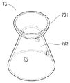
本実施形態において、エアタンク7は、ケーシング3の掘削部側(即ち、掘削ビット群5aがある側)とは反対側に連設されている。このエアタンク7は、ケーシング3よりも径小かつ気密に構成された有蓋円筒形状の胴部70と、胴部70の一端側に設けられた連結ジョイント71と、胴部70の他端側に設けられた連結体72と、胴部70内に設けられたエア流通制御部材73とを有する。また、エアタンク7には、円筒形状のアタッチメント74が外嵌めして取り付けられており、このアタッチメント74はエアタンク7に着脱可能な構造である(図3(b)参照)。
In the present embodiment, the
胴部70は、ケーシング3よりも径小であることにより、アタッチメント74取着時において、アタッチメントの最大径部分74Mとケーシングの最大径部分3Mとが同一ないしアタッチメント74の方が僅かに径小(以下「略同一」という)となるように設定されており(図5参照)、これにより、掘削作業の際に、ケーシングの最大径部分3Mから設定した当初設定値よりも掘削穴H1の穴径が拡張することなく、排土を可能にしている(図10参照)。また、胴部70は、気密に構成されていることにより、外部から供給されたエアを高圧状態で一時貯留することができる。
Since the
連結ジョイント71は、その回転軸心71Rとエアタンクの回転軸心7Rとが一致する六角柱状であって、基端がエアタンク7に取り付けられていると共に、先端が自由端で開口した開口部711が形成されており、この開口部711からエアタンク7内に連通した流通路712が形成されている(図6参照。回転軸心71Rと回転軸心7Rは図6にのみ記載している)。この連結ジョイント71により、エアタンク7と後述する吊下軸体84とが回転可能に接続されると共に、吊下軸体84に接続されたエア供給管841を介して外部のエア供給源からエアタンク7へエアが供給される(図1、図6参照)。
The connecting joint 71 has a hexagonal columnar shape in which the
連結体72は、掘削装置2aと連結するための部材であり、一端がエアタンク7側に開口すると共に、他端が接続されるピストン部材41側に開口した貫通穴721が、周方向に略等間隔で複数(本実施形態においては合計4つ)形成されている。この連結体72により、エアタンク7と掘削装置2aが連結でき、各貫通穴721を介して、エアタンク7内のエアを対応する各ピストン部材41に供給することができる(図6参照。なお、図6中でエアの流れ方向を矢印AFとして示している)。
The connecting
エア流通制御部材73は、エアタンク7内において連結体72表面に配置された盃(さかずき)状の部材であり、ボウル状の受部731と、受部731を支える略円錐台状の支持体732を有する。このエア流通制御部材73により、エアタンク7内で連結ジョイント71を通じて供給されるエアの流れ方向を(図6で示す矢印方向のように)制御することができる。詳しくは、最初に、受部731が連結ジョイント側71から供給されるエアを直接受け、その後、エアは、受部731に当たって跳ね返ると共にエアタンク7内で旋回し、各々異なるタイミングで連結体72の貫通穴721に流入することで、エアの流通が制御される。このように、エアタンク7内のエアの流れを変えることにより、エアタンク7からピストン部材41に導入されるエアの到達時間を変えることができる(図6、図9参照)。
The air
アタッチメント74は、その胴部外周面740に螺旋羽根741が設けられており、螺旋羽根741には周方向に等間隔で係合凹部742が形成されている(図3参照)。なお、この螺旋羽根741の螺旋方向は、ケーシング3に設けられた螺旋羽根321と同じである。この螺旋羽根741は、掘削作業の際に掘削装置2aの回転に伴って作用し、これによって、掘削穴H1の奥から掘削穴の穴口H2方向に送られてエアタンク7の位置まで至った排土を、掘削穴の穴口H2へ更に送ることができる(図10参照)。
The
そして、アタッチメント74は、エアタンク7に着脱可能な構造であることにより、掘削作業によって螺旋羽根741が破損した場合であっても、アタッチメント74を入れ替えるだけで済むため、作業コスト低減に寄与する。但し、前述の構成に限定するものではなく、例えば、エアタンク7の胴部70に螺旋羽根を直に設ける等の態様を除外するものではない。
Since the
なお、螺旋羽根741は、エアタンク7への取り付け時において、アタッチメントの最大径部分74M(即ち、螺旋羽根741の突出先端の位置)がケーシングの最大径部分3Mと略同一(同一ないし僅かに径小)となるように設定されており、これにより、掘削作業の際に、掘削穴H1を当初設定値よりも拡張することなく、排土を可能にしている(図5、図10参照)。
When the
また、この係合凹部742は、後述する回転駆動装置8の係止凸条部(図示省略)と嵌合し、回転駆動装置8からの駆動力をエアタンク7に伝達し、エアタンク7を含む掘削装置2aを回転させることができる。なお、エアタンク7とアタッチメント74との間には係合構造部(図示省略)が設けられており、この係合構造部によって、取り付けたアタッチメント74がエアタンク7の周りを空転しないで一体となって軸周方向に回転するようにしてある。この係合構造部は、例えば、凹部と凸部、固定ピンとピン穴等の公知の係合構造を採用することができる。
Further, the engaging recess 742 is fitted with a locking convex portion (not shown) of the rotary drive device 8 described later, transmits the driving force from the rotary drive device 8 to the
<回転駆動装置>
本実施の形態において、回転駆動装置8は、上下方向に貫通した挿通穴811が形成された回転テーブル81を有する本体部80と、本体部80を支持するアウトリガー構造の支持脚82を備えている。回転テーブル81は、油圧モータ、ギヤ装置等で構成される駆動部(図示省略)を有する。また、回転テーブル80の挿通穴811の内壁には、係止凸条部(図示省略)が挿通穴811の中心軸線に沿う方向に形成されている。
<Rotation drive device>
In the present embodiment, the rotation driving device 8 includes a
この回転駆動装置8は、前述の構成を備えることにより、掘削装置2aを回転テーブル81の挿通穴811に通した際に、本装置に設けた係止凸条部と、掘削装置2aの螺旋羽根321、741に形成された係止凹部324、742とがスライド可能に係止され、これによって、回転駆動装置8に取り付けられた掘削装置2aは、その自重により下降可能な状態となる。そして、係止凸条部と係止凹部324、742とが係止状態にあるため、回転駆動装置8からの駆動力が掘削装置2aに付与され、掘削装置2aを水平方向に回転駆動させることができる。なお、回転駆動装置8は、例えば、特開2011−26955に開示されているような公知構造を有しているので、構造および作用の説明は上記概略の説明に止め、詳細については省略する。
By providing the above-mentioned configuration, the rotary drive device 8 has a locking ridge provided in the device and a spiral blade of the
〔第2実施形態〕
図11および図12に示す掘削装置2bは、前述の掘削装置2aに第1配置態様52である掘削ビット群5bを適用したものである。また、エアタンク7bは、胴部70の外面において、螺旋羽根に代えてフラットバー743を適用している。なお、掘削装置2bについても、前述の回転式掘削機1aにおける回転駆動装置8を使用可能であるが説明を省略する。加えて、回転式掘削機1aで説明した部分(ケーシング、駆動ユニット、掘削ビット)との共通部分には同じ符号を付してその構造および作用の説明を省略し、相違する点のみ説明する。
[Second Embodiment]
The
(掘削装置)
掘削装置2bは、ケーシング3b、ケーシング3bに搭載された駆動ユニット4、および、複数の掘削ビット6D1、6E1、6E2(以下、これら全ての説明の際には「6D1〜6E2」という)により構成された第1配置態様52を有する掘削ビット群5bを備えている。
(Drilling equipment)
The
<ケーシング、駆動ユニット、エアタンク>
本実施形態において、ケーシング3bのチャックガイド36に形成された掘削ビット嵌挿用の貫通穴は、周方向に略等間隔で合計3つ形成され、また、駆動ユニット4は、ケーシング3b内に格納された3本のピストン部材41により構成されている(図示省略)。なお、ピストン部材41は、各々異径で、内蔵するピストン(図示省略)の重量が相違するように設定してある(図12参照)。
<Casing, drive unit, air tank>
In the present embodiment, a total of three through holes for inserting the excavation bit formed in the
具体的に、本実施形態の駆動ユニット4では、時計回り周方向の順で、後述する掘削ビット6D1に連結されるピストン部材41のピストンは、直径が10インチ(254mm)で重量が46kgであり、この掘削ビット6D1の時計回り側に隣接する掘削ビット6E1に連結されるピストン部材41のピストンは、直径が8インチ(203.8mm)で重量が31kgであり、この掘削ビット6E1の時計回り側に隣接する掘削ビット6E2に連結されるピストン部材41のピストンは、直径が6インチ(152.4mm)で重量が23kgに設定されており、この駆動ユニット4によれば、掘削装置2aと同様に、装置全体の重量増加、作動流体(エア)の消費量増加を必要最小限に抑えつつも、硬岩掘削時における中央凸部H6の形成抑止および中央変形部H7の発生抑制の各効果を更に高めることができる。
Specifically, in the
フラットバー743は、エアタンク7bの胴部70に設けられた断面略四角形状でエアタンク7bの長軸方向に沿って延びた凸条であり、エアタンク7bの軸周方向に所要の間隔で複数(本実施形態では4箇所。図11参照)設けられている。
The
フラットバーが設けられた掘削装置2bを使用する場合、回転駆動装置は、回転テーブルを、第1実施形態の説明で述べた挿通穴の内壁に係止凸条部が形成されたものに代えて、係止凹部が挿通穴の中心軸線に沿う方向に形成されたものにする。この場合、回転駆動装置は、前述の構成を備えることにより、掘削装置2bを回転テーブルの挿通穴に通した際に、本装置に設けた係止凹部と、掘削装置2bのフラットバー743とがスライド可能に係止され、これによって、回転駆動装置に取り付けられた掘削装置2bは、その自重により下降可能な状態となる。そして、フラットバー743と係止凹部とが係止状態にあるため、回転駆動装置からの駆動力が掘削装置2bに付与され、掘削装置2bを水平方向に回転駆動させることができる。
When using an
<掘削ビット、掘削ビット群>
図12を参照する。掘削ビット群5bは、ケーシング3bの被掘削物側に設けられ、駆動力を受けてケーシング3bの軸方向に進退動可能な複数の掘削ビット6D1〜6E2で構成され、各打撃面65bがケーシング3bの回転軸心3Rの周りに配置されている。
<Excavation bit, excavation bit group>
See FIG. The
掘削ビット群5bは、ケーシング3bに設けられ、打撃面65bから打撃方向に突出する突条打撃部655がケーシング3bの周縁部に沿う部分に形成された複数の掘削ビット6D1〜6E2が、被掘削物Hに対して突条打撃部655によって、最初の打撃を加えることができるように構成されている。これにより、掘削装置2bは、掘削装置2aと同様、軟質層H5のみならず硬岩H4に対処可能であるため、機材の入れ替えを行うことなく軟質層H5および硬岩H4のいずれにも対応することができ、機材の入れ替えによる余計な手間と時間を省略することができる。加えて、硬岩掘削時にも、比較的低騒音かつ低振動で掘削作業を行うことができる。
The
掘削ビット6D1〜6E2は、各打撃面65bの回転軸心3R側に角部67bが形成されている。そして、掘削ビット群5bは、打撃面65の1つ(掘削ビット6D1の打撃面)のみが回転軸心3Rと重複して配置された第1配置態様52で、各打撃面65bの回転軸心3R側の縁部が回転軸心3Rの近傍で近接するように集合させてある。各打撃面65bは、ケーシング3の回転軸心3Rの略直交面上にあって、被掘削物Hを打撃することができる。
The excavation bits 6D1 to 6E2 have
そして、掘削ビット6D1〜6E2は、掘削装置2aと同様に、ケーシングの回転軸心3Rとその近傍に殆ど隙間が空かないように各掘削ビット6D1〜6E2を配置することができると共に、掘削ビット群5bを、前述の回転軸心重複配置である第1配置態様52にすることができる。
As for the excavation bits 6D1 to 6E2, like the
この回転軸心重複配置によれば、掘削ビット6D1の打撃面65bを回転軸心3Rとその近傍に常時重複した状態にすることができ、掘削ビット6D1の回転方向への移動の際に、角部67bよりも広い領域である掘削ビット6D1の打撃面65bが、回転軸心3Rとその近傍を常時通過しながら掘削するので、角部67bおよび角部67bにある少数のチップ651への負荷集中を緩和することができ、これによって、硬岩掘削時における中央凸部H6形成を抑制し、中央変形部H7の発生も抑制することができる。
According to this rotation axis overlapping arrangement, the
更に、本実施形態において、前述の第2配置態様52が、回転軸心方向視で、掘削ビット6D1において回転外周から回転軸心3Rに向かって延出する角部67bの近傍にある打撃面65bの一部が、回転軸心3Rと重複して配置されている。この構成により、前述の打撃面65bと回転軸心3Rとが十分な余裕を持って重複した態様の回転軸心重複配置にすることができ、回転掘削作業時に、打撃面65bの一部が回転軸心3Rとその近傍に確実に常時重複した状態で掘削するので、これによって、硬岩掘削時における中央凸部H6の形成抑止および中央変形部H7の発生抑制の各効果を更に高めることができる。
Further, in the present embodiment, the above-mentioned
更に詳しくは、この掘削ビット群5bは、掘削ビット6D1が1つと、同一形状である一組の掘削ビット6E1、6E2の2つの、合計3つを三叉状に組み合わせて構成されており、掘削ビット6D1の角部近傍の打撃面65bが回転軸心3Rを越えて(回転軸心3Rを含んで、とも換言できる)配置されると共に、各掘削ビット6E1、6E2は、各々が回転軸心3Rを通過する掘削部の直径線L2を挟んで隣接配置されている。
More specifically, the
そして、掘削ビット6D1と掘削ビット6E1、6E2は、後述するように打撃面65b等の形状および大きさが相違しており(掘削ビット6D1よりも掘削ビット6E1、6E2の方が小さく設定されている)、これによって、回転軸心方向視で、掘削ビット6D1の打撃面65bのみが回転軸心3Rと重複すると共に、掘削ビット6E1、6E2は、辺部66bおよび角部67bのいずれもが回転軸心3Rと重複しない構成となっている。更に、掘削ビット6D1と掘削ビット6E1、6E2の角部67bは、回転軸心3Rを基準として、回転軸心3Rからケーシング3bの外周縁までの距離の約5.4%となる箇所に配置されている。
The excavation bit 6D1 and the excavation bits 6E1 and 6E2 are different in shape and size such as the
掘削ビット6D1は、チャックガイドへの取着状態においてケーシング3bの胴部外面31の一部に沿う形状で配置される端面視円弧状の第1側壁面624aと、第1側壁面624aの一の側縁と接続し、取着状態において回転軸心3R側に延設された第2側壁面624bと、第1側壁面624aの他の側縁に接続し、取着状態において回転軸心3R側に延設された第3側壁面624cと、第2側壁面624bの第1側壁面624aと反対側縁に接続し、回転軸心3R側かつヘッド部(符号省略)の水平長軸方向に向けて延設された第4側壁面624dと、第3側壁面624cの第1側壁面624aと反対側端に接続し、ケーシング3bの回転軸心3R側かつヘッド部の水平長軸方向に向けて延設されて第4側壁面624dの第2側壁面624bと反対側端に接続して鋭角な角部67bを構成する第5側壁面624eと、からなる。そして、打撃面65bにおいて第4側壁面624dと第5側壁面624eに対応する辺部66bの長さが等辺であり、第2側壁面624bと第3側壁面624cに対応する辺部66bの長さが等辺となる構成となっている(図12参照)。
The excavation bit 6D1 is one of a first
一方、掘削ビット6E1、6E2は、第1側壁面624aについては掘削ビット6D1と同様の構成であるが、第2側壁面624bに対応する辺部66bの方が第3側壁面624cに対応する辺部66bよりも長い不等辺であり、かつ、第5側壁面624eに対応する辺部66bの方が第4側壁面624dに対応する辺部66bよりも長い不等辺である点で掘削ビット6D1と相違する。
On the other hand, the excavation bits 6E1 and 6E2 have the same configuration as the excavation bit 6D1 for the first
掘削ビット6D1と掘削ビット6E1、6E2の打撃面65bを前述の形状にすることで、各掘削ビット6D1〜6E2を、ケーシング3bの回転軸心3Rに殆ど隙間が空かないように配置することができると共に、掘削ビット群5bを、前述の回転軸心重複配置である第1配置態様52にすることができる。
By forming the
〔変形例〕
なお、本発明には、第1実施形態および第2実施形態(以下「第1・第2実施形態」と省略する)において説明した態様のほか、以下の変形例に記載した態様も含まれる。
[Modification example]
In addition to the embodiments described in the first embodiment and the second embodiment (hereinafter abbreviated as "first and second embodiments"), the present invention also includes the embodiments described in the following modifications.
<掘削ビット群および掘削ビット>
(変形例1、変形例2)
図13(a)は図7に示した掘削ビット群5aの他の態様である変形例1、図13(b)は図12に示した掘削ビット群5bの他の態様である変形例2である。図13を参照して変形例1〜2について説明する。なお、掘削ビット群5cおよび掘削ビット群5dは、後述する相違点を除き、第1・第2実施形態と同様であるため、その構造および作用効果の説明は省略する。
<Excavation bit group and excavation bit>
(Modification example 1, modification 2)
13 (a) is a
変形例1である掘削ビット群5cは、図7に示す掘削ビット群5aと同様に4つの掘削ビット6F1、6F2、6F3、6F4(以下「6F1〜6F4」という)からなる点において同様であるが、前述の第2配置態様51を適用せず、各掘削ビット6F1〜6F4の先端に位置する角部67cが回転軸心3Rに非重複配置であり、角部67cを挟む各辺部の長さが同一である(等辺)構成となっており、かつ、各掘削ビット6F1〜6F4が、打撃面の形状を含む構造が同一である点で、掘削ビット群5aと異なる。
The
掘削ビット群5cによれば、各掘削ビット6F1〜6F4が同一構造であるため、掘削ビット群5aのように2種類の掘削ビットを製造、購入あるいは保管する必要がなく、一種類のみの調達で済む。これにより、例えば、交換部品または予備部品として使用する際に、どの掘削ビットが欠損しても1種類の掘削ビットを準備するだけでよいので、一方の種類の掘削ビットが余るといった無駄を減らすことができ、また、保管の際の省スペース化を図ることができ、更には、現場に搬入する交換部品等の点数を減らすこともできる。
According to the
変形例2である掘削ビット群5dは、図12に示す掘削ビット群5bと同様に3つの掘削ビット6G1、6G2、6G3(以下「6G1〜6G3」という)からなる点において同様であるが、前述の第1配置態様52を適用せず、各掘削ビット6G1〜6G3の先端に位置する角部67dが回転軸心3Rに非重複配置であり、角部67dを挟む各辺部の長さが同一である(等辺)構成となっており、かつ、各掘削ビット6G1〜6G3が、打撃面の形状を含む構造が同一である点で、掘削ビット群5bと異なる。
The
掘削ビット群5dによれば、各掘削ビット6G1〜6G3が同一構造であるため、掘削ビット群5bのように2種類の掘削ビットを製造、購入あるいは保管する必要がなく、一種類のみの調達で済む。これにより、例えば、交換部品または予備部品として使用する際に、どの掘削ビットが欠損しても1種類の掘削ビットを準備するだけでよいので、一方の種類の掘削ビットが余るといった無駄を減らすことができ、また、保管の際の省スペース化を図ることができ、更には、現場に搬入する交換部品等の点数を減らすこともできる。
According to the
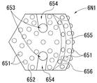
(変形例3、変形例4)
第1・第2実施形態において、平坦打撃部652の開口部653は各掘削ビットに1つであるが、これに限定するものではなく、例えば、図14に示す変形例3の掘削ビット6P1、あるいは、図15に示す変形例4の掘削ビット6N1のように、エアの流路をヘッド部内で分岐させ、平坦打撃部652に形成される開口部653を2以上にすることもできる。
(
In the first and second embodiments, the
また、第1・第2実施形態において、排気ガイド溝654は、開口部653の口縁から異なる向きで2条(開口部653を中心に2条が合流するので、1条とも表現可能)形成されているが、これに限定するものではなく、例えば、形成される排気ガイド溝が1条または3条以上であってもよいし、また、例えば第1側壁面等の同一方向に向けて形成する態様等であってもよい。例えば、図14に示す変形例3の掘削ビット6P1の排気ガイド溝654は、2つの開口部653の口縁から異なる向きで4条(開口部653を中心に2条が合流するので、2条とも表現可能)形成されており、図15に示す変形例4の掘削ビット6N1の排気ガイド溝654は、2つの開口部653の口縁から異なる向きで2条形成されている。
Further, in the first and second embodiments, the
前述の各実施形態および各変形例において、掘削ビット6A1等にはチップ651を植設して分散配置されているが、これに限定するものではなく、例えば、打撃面に凹溝を複数条形成し、平坦面と凹部が連続した結果、平坦面が実質的に凸部としてチップの機能を代替するようにした態様等であってもよい。
In each of the above-described embodiments and modifications,
前述の各実施形態または各変形例における掘削ビット群を構成する配置態様において、各掘削ビットの角部は、その先端が、ケーシングの回転軸心を基準として、回転軸心からケーシングの外周端までの距離の5%〜30%の半径領域の内側に収まるように設定されていることが好ましい。5%未満であると角部が回転軸心に寄り過ぎ、硬岩掘削時において掘削穴の奥側中央に、図18(c)に示すような中央凸部H6が形成され、これに伴う掘削ビットに中央変形部H7が発生するおそれがあるため、好ましくなく、一方、30%を超えると、ピストン部材の直径よりも小さくなる掘削ビットが生じ、打撃力の伝達効率が低下するおそれがあるため、やはり好ましくない。 In the arrangement mode constituting the excavation bit group in each of the above-described embodiments or modifications, the tip of each excavation bit is from the rotation axis to the outer peripheral edge of the casing with reference to the rotation axis of the casing. It is preferable that it is set so as to fit inside a radius region of 5% to 30% of the distance. If it is less than 5%, the corners are too close to the center of rotation, and a central convex portion H6 as shown in FIG. 18C is formed in the center of the back side of the excavation hole during hard rock excavation. It is not preferable because the central deformed portion H7 may be generated in the bit. On the other hand, if it exceeds 30%, an excavation bit smaller than the diameter of the piston member is generated, and the transmission efficiency of the striking force may decrease. After all, it is not preferable.
前述の各実施形態または各変形例において、ヘッド部62は、打撃面65の面形状が五角形に形成されているが、これに限定するものではなく、例えば、打撃面の面形状は、半円形や、扇形、略三角形または略方形の四角形等であってもよく、掘削装置へ複数の掘削ビットを装着した状態において、一の掘削ビットの回転軸心側に向いた側壁部が、対向位置または隣接位置にある他の掘削ビットの回転軸心側に向いた側壁部と、互いに殆ど隙間が空かないように突き合わせることが可能な形状であればよい。また、ヘッド部は、角柱状のみならず、底面が打撃面となる錐台状等であってもよい。
In each of the above-described embodiments or modifications, the
前述の各実施形態または各変形例において、突条打撃部655は、傾斜面656の傾斜角度65Aが35°に設定されているが、これに限定するものではなく、例えば、同傾斜角度は20°〜60°の範囲内に設定されることが好ましく、更に好ましくは30°〜50°である。この傾斜角度が20°未満では打撃面全体における傾斜面が広くなり過ぎて全体的に平坦となり、硬岩に食い込ませるような打撃力が発揮しにくくなり、更に、掘削穴に中央凸部が発生するおそれがあるため、好ましくなく、一方、この傾斜角度が60°を超えると、突条打撃部が尖鋭に突出し過ぎて、硬岩打撃時に突条打撃部が欠けやすくなり、やはり好ましくないためである。
In each of the above-described embodiments or modifications, the
前述の各実施形態または各変形例において、突条打撃部655は、その突出高さ65Hが平坦打撃部652から3cmに設定されているが、これに限定するものではなく、例えば、この高さは平坦打撃部から2cm〜6cmの高さであることが好ましく、更に好ましくは3〜5cmである。突出高さが2cm未満では平坦打撃部からの突出高さが低いため、硬岩に食い込ませるような打撃力が発揮しにくいため、好ましくなく、一方、6cmを超えると突条打撃部が突出し過ぎて、硬岩を打撃した際に突条打撃部が欠けやすくなり、やはり好ましくないためである。
In each of the above-described embodiments or modifications, the
<ケーシング>
(変形例5、変形例6)
第1・第2実施形態において、ケーシング3の胴部外面31に螺旋羽根321および補強リブ322を設けているが、これに限定するものではなく、例えば、図16(a)に示す変形例5の掘削装置2cのように、ケーシング3cの胴部外周の長手方向に亘って螺旋羽根321aを設ける態様、図16(b)に示す変形例6の掘削装置2dのように、ケーシング3bの胴部外周の長手方向に亘るケーシングの回転軸心と平行なフラットバー325を設ける態様、等の各種変形を除外するものではない。
<Casing>
(Modification 5 and Modification 6)
In the first and second embodiments, the
なお、ケーシング3内において、ケーシング3内壁と駆動ユニット4の間に形成された空隙には、防振材または防音材として砂等の粒状物を充填してもよい(図示省略)。また、駆動ユニット4を構成する各ピストン部材41のピストン411の重量を不均一に設定している場合、作動不良を防止すべく、この空隙にカウンターウェイトを配置しても良い(図示省略)。
In the
また、前述の各実施形態または各変形例における掘削装置2a等は、ケーシング3とエアタンク7が着脱可能な構造であるが、これに限定するものではなく、例えば、ケーシングとエアタンクが着脱不能に一体となった構造を除外するものではない。また、この着脱不能型の掘削装置では外周を面一とし、長軸方向に亘る螺旋羽根またはフラットバーを設けてもよい。
Further, the
<駆動ユニット>
第1・第2実施形態において、駆動ユニット4は、前述の通りケーシング内の3本又は4本のピストン部材41により構成されるが、これに限定するものではなく、例えば、掘削ビット毎に少なくとも1本のピストン部材が充てられることが好ましい。
<Drive unit>
In the first and second embodiments, the
前述の各実施形態または各変形例において、駆動ユニット4は、ピストン部材41が各々異径で、内蔵するピストン411の重量が相違するように設定された態様(全部相違態様)であるが、これに限定するものではなく、例えば、各ピストン部材の管径が全て同径でピストンも同重量のものとする態様(全部共通態様)、最大面積を有する打撃面にのみ最大打撃力のピストン部材をあて、その他の打撃面については最大打撃力のピストン部材よりも打撃力の弱い共通のピストン部材をあてる態様(一部共通態様)等であってもよい。また、ピストン部材の管径は共通で、内蔵するピストンの長短により重量(打撃力)に変化をつける態様であってもよい。
In each of the above-described embodiments or modifications, the
駆動ユニットが前述の全部共通態様の場合、打撃力に差を付けることはできないが、部品を共通化することにより、製造時および運用時のコスト抑制を図ることができる。 When the drive unit has the above-mentioned all common modes, it is not possible to make a difference in the striking force, but by sharing the parts, it is possible to reduce the cost during manufacturing and operation.
また、駆動ユニットが一部共通態様の場合、例えば、駆動ユニットがピストン部材4本組みの場合、ピストンの重量が相違する2種類のピストン部材を2組組み合わせる態様、駆動ユニットがピストン部材3本組みの場合、最大面積を有する打撃面1つにのみ最大打撃力のピストン部材をあて、その他の打撃面2つについてはやや打撃力の弱い共通のピストン部材をあてる態様としてもよく、この態様によれば、掘削ビット毎に打撃力に差を付けることができると共に、全部相違態様よりも部品点数を少なく(一部部品を共通化)することができ、製造時および運用時のコスト抑制を図ることができる。 Further, when the drive unit has a partially common mode, for example, when the drive unit is a set of four piston members, a mode in which two sets of two types of piston members having different piston weights are combined, and a drive unit is a set of three piston members. In the case of, the piston member having the maximum striking force may be applied to only one striking surface having the maximum area, and the common piston member having a slightly weak striking force may be applied to the other two striking surfaces. For example, it is possible to make a difference in striking force for each excavation bit, and it is possible to reduce the number of parts (some parts are shared) compared to all different modes, and to reduce costs during manufacturing and operation. Can be done.
更に、駆動ユニットは、前述の構造に限定されるものではなく、例えば、複数のスリーブが形成された一機のピストン部材であって、各スリーブにピストンが進退可能に収容された態様等、複数のピストンが個別に進退可能な構造であれば特に限定されない。なお、この場合についても、前述の通り、各ピストンの重量が相違するように設定することもできる。 Further, the drive unit is not limited to the above-mentioned structure, for example, a single piston member in which a plurality of sleeves are formed, and a plurality of modes such that the piston is accommodated in each sleeve so as to be able to advance and retreat. There is no particular limitation as long as the pistons have a structure that allows them to move forward and backward individually. Also in this case, as described above, the weight of each piston can be set to be different.
<貯留タンク>
前述の各実施形態または各変形例において、エア流通制御部材73は盃形状であるが、これに限定するものではなく、例えば、円周方向に所定間隔で穴が開いたディスク状の板体を貯留タンク内側の連結面表面沿って回動可能に取り付け、回転に伴って連結体に形成された前述の貫通穴を断続的に塞ぐようにした構造のもの、貯留タンクからピストン部材に至る各々の経路の長さに長短を設ける構造のもの等、貯留タンク内のエアが各ピストン部材に同じタイミングで流れ込まない形状又は構造であれば、特に限定されるものではない。
<Storage tank>
In each of the above-described embodiments or modifications, the air
また、貯留タンクの連結ジョイントに形成される開口部および流通路は他にも複数形成されていてもよく(本段落において便宜上これらを「他の流通路」という)、この場合、例えば、土質補強材等の流体を他の流通路に流し、貯留タンク内を通過する供給管を介して、掘削装置の被掘削物側から掘削穴内に排出することができる。 In addition, a plurality of other openings and flow passages formed in the connecting joint of the storage tank may be formed (these are referred to as "other flow passages" for convenience in this paragraph), and in this case, for example, soil reinforcement. A fluid such as a material can flow into another flow path and be discharged into the excavation hole from the excavated object side of the excavator through a supply pipe passing through the storage tank.
<回転駆動装置>
第1実施形態で示した回転駆動装置8は、掘削装置2aの自重により下降可能な状態で掘削装置2aに回転力を付与する態様であるが、これに限定するものではなく、例えば、回転駆動装置は取り付けた掘削装置を被掘削物側へ押し出す機構を有する態様であってもよく、その場合、特に岩壁等の壁状の被掘削物に対して好適に使用することができる。また、第1実施形態で示した回転駆動装置8は、テーブル状に設けられた態様であるが、これに限定するものではなく、例えば、掘削装置の胴部に取り付ける抱持部を有し、抱持部を介して掘削装置に回転力を付与する態様の回転駆動装置等、掘削装置に回転力を付与可能な装置であれば、特に限定されるものではない。
<Rotation drive device>
The rotary drive device 8 shown in the first embodiment is a mode in which a rotational force is applied to the
本明細書および特許請求の範囲で使用している用語と表現は、あくまでも説明上のものであって、なんら限定的なものではなく、本明細書および特許請求の範囲に記述された特徴およびその一部と等価の用語や表現を除外する意図はない。また、本発明の技術思想の範囲内で、種々の変形態様が可能であるということは言うまでもない。また、第一、第二などの言葉は、等級や重要度を意味するものではなく、一つの要素を他の要素から区別するために使用したものである。 The terms and expressions used in the present specification and the claims are for explanatory purposes only and are not limited in any way. The features described in the present specification and the claims and the features thereof and the like thereof. There is no intention to exclude terms or expressions that are equivalent to some. Further, it goes without saying that various modifications are possible within the scope of the technical idea of the present invention. In addition, words such as first and second do not mean grade or importance, but are used to distinguish one element from another.
1 回転式掘削機
2a、2b、2c、2d 掘削装置
3、3b、3c、3d ケーシング
3R 回転軸心
3C 周方向
31 胴部外面
32 スクリュー部
321、321a 螺旋羽根
322 補強リブ
324 係合凹部
325 フラットバー
33 貯留タンク側蓋体
331 挿入穴
34 被掘削物側蓋体
341 挿入穴
35 チャックガイド
351 貫通穴
36 ドライブチャック
370 ボルト
371 ナット
3V 仮想面
3M ケーシングの最大径部分
4 駆動ユニット
41 ピストン部材
411 ピストン
412 シリンダー
5a、5b、5c、5d 掘削ビット群
51 第2配置態様
52 第1配置態様
6A1、6A2、6B1、6B2、6D1、6E1、6E2、6F1、6F2、6F3、6F4、6G1、6G2、6G3、6N1、6P1 掘削ビット
6C ケーシングの回転軸心の略直交面
61 接続軸部
611 開口部
62 ヘッド部
621 エアの流路
622 接合部
623a、624a 第1側壁面
623b、624b 第2側壁面
623c、624c 第3側壁面
623d、624c 第4側壁面
623e、624e 第5側壁面
65、65b、65c、65d 打撃面
651 チップ
652 平坦打撃部
653 開口部
654 排気ガイド溝
66、66b 辺部
67、67b、67c、67d 角部
655 突条打撃部
656 傾斜面
65A 傾斜角度
65H 突出高さ
661 縁部
7、7b 貯留タンク
7R 貯留タンクの回転軸心
70 胴部
71 連結ジョイント
71R 連結ジョイントの回転軸心
711 開口部
712 流通路
72 連結体
721 貫通穴
73 エア流通制御部材
731 受部
732 支持体
AF エアの流れ方向
74 アタッチメント
740 胴部外周面
741 螺旋羽根
742 係合凹部
743 フラットバー
74M アタッチメントの最大径部分
8 回転駆動装置
80 本体部
81 回転テーブル
811 挿通穴
82 支持脚
84 吊下軸体
841 エア供給管
H 被掘削物
H1 掘削穴
H2 掘削穴の穴口
H3 穴底面
H4 硬岩
H5 軟質層
H6 中央凸部
H7 中央変形部
L2 直径線
9 掘削装置
91 中央ビット
92 周辺ビット
93 試作機
930 掘削ビット
931 打撃面
933 角部
934 チップ
9R 回転軸心
1 Rotary excavator 2a, 2b, 2c, 2d excavator 3, 3b, 3c, 3d Casing 3R Rotating axis 3C Circumferential direction 31 Body outer surface 32 Screw part 321, 321a Spiral blade 322 Reinforcing rib 324 Engagement recess 325 Flat Bar 33 Storage tank side lid 331 Insertion hole 34 Excavated side lid 341 Insertion hole 35 Chuck guide 351 Through hole 36 Drive chuck 370 Bolt 371 Nut 3V Virtual surface 3M Maximum diameter part of casing 4 Drive unit 41 Piston member 411 Piston 412 Cylinder 5a, 5b, 5c, 5d Drilling Bit Group 51 Second Arrangement 52 First Arrangement 6A1, 6A2, 6B1, 6B2, 6D1, 6E1, 6E2, 6F1, 6F2, 6F3, 6F4, 6G1, 6G2, 6G3, 6N1, 6P1 Excavation bit 6C Approximately orthogonal surface of the rotation axis of the casing 61 Connection shaft part 611 Opening 62 Head part 621 Air flow path 622 Joint part 623a, 624a First side wall surface 623b, 624b Second side wall surface 623c, 624c 3rd side wall surface 623d, 624c 4th side wall surface 623e, 624e 5th side wall surface 65, 65b, 65c, 65d Strike surface 651 Chip 652 Flat striking part 653 Opening 654 Exhaust guide groove 66, 66b Side parts 67, 67b, 67c , 67d Square 655 Ripped striking part 656 Slope 65A Slope 65H Protrusion height 661 Edge 7, 7b Storage tank 7R Storage tank rotation axis 70 Body 71 Connection joint 71R Connection joint rotation axis 711 Opening 712 Flow passage 72 Connection body 721 Through hole 73 Air flow control member 731 Receiving part 732 Support AF Air flow direction 74 Attachment 740 Body outer circumference 741 Spiral blade 742 Engagement recess 743 Flat bar 74M Maximum diameter part of attachment 8 rotations Drive device 80 Main body 81 Rotating table 811 Insertion hole 82 Support leg 84 Suspended shaft body 841 Air supply pipe H Excavated object H1 Excavated hole H2 Excavated hole hole H3 Hole bottom H4 Hard rock H5 Soft layer H6 Central convex part H7 Center Deformation part L2 Diameter line 9 Excavator 91 Central bit 92 Peripheral bit 93 Prototype 930 Drilling Bit 931 Strike Surface 933 Corner 934 Chip 9R Rotation Axis
Claims (12)
該ケーシングに格納され、駆動力を供給可能な駆動ユニットと、
前記ケーシングに接続され、前記駆動力を受けて同ケーシングの軸方向に進退動可能な複数の掘削ビットを有し、該各掘削ビットが同ケーシングの回転軸心の周りに配置されてなる掘削ビット群と、を備え、
前記各掘削ビットは、前記駆動ユニットから供給される駆動力を受ける接続軸部、及び、該接続軸部と接続されて同接続軸部とは反対側に打撃面部が設けられたヘッド部を有し、該打撃面部は、略平坦な平坦打撃部、及び、該平坦打撃部よりも高く突出した突条打撃部を含み、該突条打撃部が前記ケーシングの回転軸心方向視で、前記掘削ビット群の外周縁に沿う縁部に沿って円弧状に形成されており、
前記駆動ユニットが、前記掘削ビット毎に相違する駆動力を付与する態様、または、一部の掘削ビットに付与する駆動力が、他の掘削ビットに付与される駆動力よりも大きくなるようにした態様、のいずれかの態様に設定されている
掘削装置。 A tubular casing that can rotate in the circumferential direction,
A drive unit that is stored in the casing and can supply driving force,
An excavation bit that is connected to the casing and has a plurality of excavation bits that can move forward and backward in the axial direction of the casing by receiving the driving force, and each excavation bit is arranged around the rotation axis of the casing. With a group,
Each of the excavation bits has a connecting shaft portion that receives a driving force supplied from the driving unit, and a head portion that is connected to the connecting shaft portion and has a striking surface portion on the opposite side of the connecting shaft portion. However, the striking surface portion includes a substantially flat flat striking portion and a ridge striking portion protruding higher than the flat striking portion, and the ridge striking portion is the excavation in the direction of the rotation axis of the casing. It is formed in an arc shape along the edge along the outer peripheral edge of the bit group.
The mode in which the drive unit applies a different driving force to each of the excavation bits, or the driving force applied to some of the excavation bits is made larger than the driving force applied to the other excavation bits. An excavator set in any of the embodiments.
該ケーシングに格納され、駆動力を供給可能な駆動ユニットと、A drive unit that is stored in the casing and can supply driving force,
前記ケーシングに接続され、前記駆動力を受けて同ケーシングの軸方向に進退動可能な複数の掘削ビットを有し、該各掘削ビットが同ケーシングの回転軸心の周りに配置されてなる掘削ビット群と、を備え、An excavation bit that is connected to the casing and has a plurality of excavation bits that can move forward and backward in the axial direction of the casing by receiving the driving force, and each excavation bit is arranged around the rotation axis of the casing. With a group,
前記各掘削ビットは、前記駆動ユニットから供給される駆動力を受ける接続軸部、及び、該接続軸部と接続されて同接続軸部とは反対側に打撃面部が設けられたヘッド部を有し、該打撃面部は、略平坦な平坦打撃部、及び、該平坦打撃部よりも高く突出した突条打撃部を含み、該突条打撃部が前記ケーシングの回転軸心方向視で、前記掘削ビット群の外周縁に沿う縁部に沿って円弧状に形成されており、Each of the excavation bits has a connecting shaft portion that receives a driving force supplied from the driving unit, and a head portion that is connected to the connecting shaft portion and has a striking surface portion on the opposite side of the connecting shaft portion. However, the striking surface portion includes a substantially flat flat striking portion and a ridge striking portion protruding higher than the flat striking portion, and the ridge striking portion is the excavation in the direction of the rotation axis of the casing. It is formed in an arc shape along the edge along the outer peripheral edge of the bit group.
前記掘削ビット群が、前記打撃面の1つのみが前記回転軸心と重複して配置された第1配置態様、または、前記打撃面の前記回転軸心側に角部が形成され、同回転軸心を挟んで対向配置された一組の同打撃面の前記回転軸心側の縁部のみが同回転軸心と重複し、かつ、前記角部の先端が同回転軸心と重複しないように配置された第2配置態様、のいずれかによって、前記各打撃面の前記回転軸心側の縁部が同回転軸心の近傍で近接するように集合させた構成であるIn the first arrangement mode in which only one of the striking surfaces of the excavation bit group is arranged so as to overlap the rotation axis, or a corner portion is formed on the rotation axis side of the striking surface and the rotation is the same. Only the edge of the set of the same striking surfaces arranged so as to face each other across the axis on the rotation axis side overlaps with the rotation axis, and the tip of the corner does not overlap with the rotation axis. According to any of the second arrangement modes arranged in the above, the edges of each striking surface on the rotation axis side are assembled so as to be close to each other in the vicinity of the rotation axis.
掘削装置。Drilling equipment.
請求項2に記載の掘削装置。The excavator according to claim 2.
前記各掘削ビットは、前記駆動ユニットから供給される駆動力を受ける接続軸部、及び、該接続軸部と接続されて同接続軸部とは反対側に打撃面部が設けられたヘッド部を有し、該打撃面部は、略平坦な平坦打撃部、及び、該平坦打撃部よりも高く突出した突条打撃部を含み、該突条打撃部が前記ケーシングの回転軸心方向視で、前記掘削ビット群の外周縁に沿う縁部に沿って円弧状に形成されており、Each of the excavation bits has a connecting shaft portion that receives a driving force supplied from the driving unit, and a head portion that is connected to the connecting shaft portion and has a striking surface portion on the opposite side of the connecting shaft portion. However, the striking surface portion includes a substantially flat flat striking portion and a ridge striking portion protruding higher than the flat striking portion, and the ridge striking portion is the excavation in the direction of the rotation axis of the casing. It is formed in an arc shape along the edge along the outer peripheral edge of the bit group.
前記駆動ユニットが、前記掘削ビット毎に相違する駆動力を付与する態様、または、一部の掘削ビットに付与する駆動力が、他の掘削ビットに付与される駆動力よりも大きくなるようにした態様、のいずれかの態様に設定されている掘削装置と、The mode in which the drive unit applies a different driving force to each of the excavation bits, or the driving force applied to some of the excavation bits is made larger than the driving force applied to the other excavation bits. An excavator set in any of the modes,
該掘削装置に回転力を付与する回転駆動装置と、を備えるA rotary drive device for applying a rotational force to the drilling device is provided.
回転式掘削機。Rotary excavator.
前記各掘削ビットは、前記駆動ユニットから供給される駆動力を受ける接続軸部、及び、該接続軸部と接続されて同接続軸部とは反対側に打撃面部が設けられたヘッド部を有し、該打撃面部は、略平坦な平坦打撃部、及び、該平坦打撃部よりも高く突出した突条打撃部を含み、該突条打撃部が前記ケーシングの回転軸心方向視で、前記掘削ビット群の外周縁に沿う縁部に沿って円弧状に形成されており、Each of the excavation bits has a connecting shaft portion that receives a driving force supplied from the driving unit, and a head portion that is connected to the connecting shaft portion and has a striking surface portion on the opposite side of the connecting shaft portion. However, the striking surface portion includes a substantially flat flat striking portion and a ridge striking portion protruding higher than the flat striking portion, and the ridge striking portion is the excavation in the direction of the rotation axis of the casing. It is formed in an arc shape along the edge along the outer peripheral edge of the bit group.
前記掘削ビット群が、前記打撃面の1つのみが前記回転軸心と重複して配置された第1配置態様、または、前記打撃面の前記回転軸心側に角部が形成され、同回転軸心を挟んで対向配置された一組の同打撃面の前記回転軸心側の縁部のみが同回転軸心と重複し、かつ、前記角部の先端が同回転軸心と重複しないように配置された第2配置態様、のいずれかによって、前記各打撃面の前記回転軸心側の縁部が同回転軸心の近傍で近接するように集合させた構成である掘削装置と、In the first arrangement mode in which only one of the striking surfaces of the excavation bit group is arranged so as to overlap the rotation axis, or a corner portion is formed on the rotation axis side of the striking surface and the rotation is the same. Only the edge of the set of the same striking surfaces arranged so as to face each other across the axis on the rotation axis side overlaps with the rotation axis, and the tip of the corner does not overlap with the rotation axis. According to any of the second arrangement modes arranged in the above, an excavator having a configuration in which the edges of each striking surface on the rotation axis side are assembled so as to be close to each other in the vicinity of the rotation axis.
該掘削装置に回転力を付与する回転駆動装置と、を備えるA rotary drive device for applying a rotational force to the drilling device is provided.
回転式掘削機。Rotary excavator.
該第1工程により設置された前記回転駆動装置によって掘削装置を回転させながら、該掘削装置の前記掘削ビットを進退させ、前記打撃面によって前記被掘削物を打撃することで同被掘削物を掘削する第2工程と、を備えるWhile rotating the excavating device by the rotary drive device installed in the first step, the excavating bit of the excavating device is moved forward and backward, and the excavated object is impacted by the striking surface to excavate the excavated object. The second step to be done
掘削方法。Excavation method.
前記ケーシングに取り付け可能で、前記駆動ユニットから供給される駆動力を受ける接続軸部と、該接続軸部と接続されて同接続軸部とは反対側に打撃面部が設けられたヘッド部とを備え、A connection shaft portion that can be attached to the casing and receives a driving force supplied from the drive unit, and a head portion that is connected to the connection shaft portion and has a striking surface portion on the opposite side of the connection shaft portion. Prepare,
前記打撃面部は、略平坦な平坦打撃部、該平坦打撃部よりも高く突出した突条打撃部、及び、該突条打撃部と前記平坦打撃部との間に形成された傾斜面を有し、The striking surface portion has a substantially flat flat striking portion, a ridge striking portion protruding higher than the flat striking portion, and an inclined surface formed between the ridge striking portion and the flat striking portion. ,
該傾斜面は、同平坦打撃部から同突条打撃部に向かう傾斜角度が20°以上60°以下の逆テーパ状であり、The inclined surface has a reverse taper shape in which the inclination angle from the flat striking portion to the strut striking portion is 20 ° or more and 60 ° or less.
前記突条打撃部は、前記ケーシングへの取着状態において、同ケーシングの回転軸心方向視で、前記掘削ビット群の外周縁に沿う縁部に沿って円弧状に形成されているThe ridge striking portion is formed in an arc shape along the edge portion along the outer peripheral edge of the excavation bit group in the state of attachment to the casing in the direction of the rotation axis of the casing.
掘削ビット。Drilling bit.
前記ケーシングに取り付け可能で、前記駆動ユニットから供給される駆動力を受ける接続軸部と、該接続軸部と接続されて同接続軸部とは反対側に打撃面部が設けられたヘッド部とを備え、A connection shaft portion that can be attached to the casing and receives a driving force supplied from the drive unit, and a head portion that is connected to the connection shaft portion and has a striking surface portion on the opposite side of the connection shaft portion. Prepare,
前記打撃面部は、略平坦な平坦打撃部、及び、該平坦打撃部よりも2cm以上6cm以下の高さで突出した突条打撃部を有し、該突条打撃部が前記ケーシングの回転軸心方向視で、前記掘削ビット群の外周縁に沿う縁部に沿って円弧状に形成されているThe striking surface portion has a substantially flat flat striking portion and a ridge striking portion protruding at a height of 2 cm or more and 6 cm or less from the flat striking portion, and the ridge striking portion is the rotation axis of the casing. In directional view, it is formed in an arc shape along the edge along the outer peripheral edge of the excavation bit group.
掘削ビット。Drilling bit.
前記各掘削ビットは、前記駆動ユニットから供給される駆動力を受ける接続軸部、及び、該接続軸部と接続されて同接続軸部とは反対側に打撃面部が設けられたヘッド部を有し、Each of the excavation bits has a connecting shaft portion that receives a driving force supplied from the driving unit, and a head portion that is connected to the connecting shaft portion and has a striking surface portion on the opposite side of the connecting shaft portion. And
該打撃面部が、The striking surface portion
略平坦な平坦打撃部、該平坦打撃部よりも高く突出した突条打撃部、及び、該突条打撃部と前記平坦打撃部との間に形成され、同平坦打撃部から同突条打撃部に向かう傾斜角度が20°以上60°以下の逆テーパ状である傾斜面を含み、前記突条打撃部が前記ケーシングの回転軸心方向視で、前記掘削ビット群の外周縁に沿う縁部に沿って円弧状に形成されている態様、A substantially flat flat striking portion, a ridge striking portion protruding higher than the flat striking portion, and a ridge striking portion formed between the ridge striking portion and the flat striking portion, and the flat striking portion to the ridge striking portion. Including an inclined surface having a reverse taper shape having an inclination angle of 20 ° or more and 60 ° or less, the ridge striking portion is on the edge along the outer peripheral edge of the excavation bit group in the direction of the rotation axis of the casing. Aspects formed in an arc along the
または、Or
略平坦な平坦打撃部、及び、該平坦打撃部よりも2cm以上6cm以下の高さで突出した突条打撃部を含み、該突条打撃部が前記ケーシングの回転軸心方向視で、前記掘削ビット群の外周縁に沿う縁部に沿って円弧状に形成されている態様、The excavation includes a substantially flat flat striking portion and a ridge striking portion protruding at a height of 2 cm or more and 6 cm or less from the flat striking portion, and the ridge striking portion is viewed in the direction of the rotation axis of the casing. A mode formed in an arc shape along the edge along the outer peripheral edge of the bit group,
のいずれかであるIs one of
掘削装置。Drilling equipment.
該掘削装置に回転力を付与する回転駆動装置と、を備えるA rotary drive device for applying a rotational force to the drilling device is provided.
回転式掘削機。Rotary excavator.
該第1工程により設置された前記回転駆動装置によって掘削装置を回転させながら、該掘削装置の前記掘削ビットを進退させ、前記打撃面によって前記被掘削物を打撃することで同被掘削物を掘削する第2工程と、を備えるWhile rotating the excavating device by the rotary drive device installed in the first step, the excavating bit of the excavating device is moved forward and backward, and the excavated object is impacted by the striking surface to excavate the excavated object. The second step to be done
掘削方法。Excavation method.
Priority Applications (1)
| Application Number | Priority Date | Filing Date | Title |
|---|---|---|---|
| JP2017252197A JP6864199B2 (en) | 2017-12-27 | 2017-12-27 | Excavator, rotary excavator, excavation method and excavation bit |
Applications Claiming Priority (1)
| Application Number | Priority Date | Filing Date | Title |
|---|---|---|---|
| JP2017252197A JP6864199B2 (en) | 2017-12-27 | 2017-12-27 | Excavator, rotary excavator, excavation method and excavation bit |
Publications (2)
| Publication Number | Publication Date |
|---|---|
| JP2019116808A JP2019116808A (en) | 2019-07-18 |
| JP6864199B2 true JP6864199B2 (en) | 2021-04-28 |
Family
ID=67304199
Family Applications (1)
| Application Number | Title | Priority Date | Filing Date |
|---|---|---|---|
| JP2017252197A Active JP6864199B2 (en) | 2017-12-27 | 2017-12-27 | Excavator, rotary excavator, excavation method and excavation bit |
Country Status (1)
| Country | Link |
|---|---|
| JP (1) | JP6864199B2 (en) |
Families Citing this family (2)
| Publication number | Priority date | Publication date | Assignee | Title |
|---|---|---|---|---|
| JP2019124009A (en) * | 2018-01-12 | 2019-07-25 | 大智株式会社 | Drilling machine, rotational drilling machine, drilling method and drilling bit |
| CN116255095B (en) * | 2023-02-09 | 2023-11-17 | 泰安中联水泥有限公司 | Equipment for accurately positioning surface mine drilling and use method |
Family Cites Families (8)
| Publication number | Priority date | Publication date | Assignee | Title |
|---|---|---|---|---|
| JPS6126796U (en) * | 1984-07-23 | 1986-02-18 | 三和機材株式会社 | Excavation head of buried pipe propulsion device |
| JPH0434231Y2 (en) * | 1986-06-06 | 1992-08-14 | ||
| JP3248091B2 (en) * | 1995-10-09 | 2002-01-21 | 東洋企画株式会社 | Double pipe perforator |
| JP2001003669A (en) * | 1999-06-23 | 2001-01-09 | Tone Corp | Multiple air hammer device and method for correcting drilling direction thereof |
| JP4318603B2 (en) * | 2004-06-30 | 2009-08-26 | 株式会社奥村組 | Drilling bit in a steel pipe for ground reinforcement |
| JP4076565B1 (en) * | 2006-12-04 | 2008-04-16 | 一功 古木 | Excavator for underground excavation, rotary excavator and underground excavation method |
| WO2008069089A1 (en) * | 2006-12-04 | 2008-06-12 | Kazunori Furuki | Excavator for underground excavating, rotary excavator and underground excavating method |
| JP5330977B2 (en) * | 2009-12-09 | 2013-10-30 | Jfeシビル株式会社 | Drilling bit, rotary percussion drilling device, and drilling bottom test method |
-
2017
- 2017-12-27 JP JP2017252197A patent/JP6864199B2/en active Active
Also Published As
| Publication number | Publication date |
|---|---|
| JP2019116808A (en) | 2019-07-18 |
Similar Documents
| Publication | Publication Date | Title |
|---|---|---|
| JP2019124009A (en) | Drilling machine, rotational drilling machine, drilling method and drilling bit | |
| JP4076554B2 (en) | Excavator, rotary excavator equipped with excavator and underground excavation method | |
| TWI407006B (en) | Drilling equipment for ground drilling, rotary drilling machines and ground drilling | |
| US9322216B2 (en) | Annulus ring hole drill | |
| JP6864199B2 (en) | Excavator, rotary excavator, excavation method and excavation bit | |
| JP2011026955A (en) | Earth excavating hammer and rotary excavator with the same | |
| JP6429098B2 (en) | Excavator using excavator | |
| JP4076551B2 (en) | Rotary excavator | |
| JP4628413B2 (en) | Underground excavation hammer and rotary excavator provided with the same | |
| JP3721381B1 (en) | Drilling device and underground excavation method | |
| JP2019132031A (en) | Casing for drilling rig, and drilling rig | |
| JP4076564B1 (en) | Excavator for underground excavation, rotary excavator and underground excavation method | |
| KR20140039409A (en) | Machine boring rock large diameter rotation type | |
| JP3234114U (en) | Excavator and rotary excavator | |
| JP6716085B2 (en) | Excavator, rotary excavator, excavation method and excavation bit | |
| JP3234002U (en) | Drilling equipment casing and drilling equipment | |
| JP7111356B2 (en) | Drilling rigs and rotary excavators | |
| KR102209256B1 (en) | Cluster drilling hammer and manufacturing method thereof | |
| JP7177471B2 (en) | Drilling rigs and rotary excavators | |
| KR101258506B1 (en) | Hammer bit structure of ground boring apparatus | |
| KR20050011865A (en) | Multi drill for excavate | |
| KR20110007344A (en) | Hammer for digging | |
| KR102566443B1 (en) | Vibration-Free Rock Crushing with 3 Free-face Excavation Method | |
| JPH0931980A (en) | Method for pressing in sheet pile | |
| JP3457238B2 (en) | Drilling mechanism of blasting rock drill |
Legal Events
| Date | Code | Title | Description |
|---|---|---|---|
| A521 | Request for written amendment filed |
Free format text: JAPANESE INTERMEDIATE CODE: A523 Effective date: 20181219 |
|
| RD05 | Notification of revocation of power of attorney |
Free format text: JAPANESE INTERMEDIATE CODE: A7425 Effective date: 20190816 |
|
| A521 | Request for written amendment filed |
Free format text: JAPANESE INTERMEDIATE CODE: A821 Effective date: 20190817 |
|
| A621 | Written request for application examination |
Free format text: JAPANESE INTERMEDIATE CODE: A621 Effective date: 20200713 |
|
| A871 | Explanation of circumstances concerning accelerated examination |
Free format text: JAPANESE INTERMEDIATE CODE: A871 Effective date: 20200713 |
|
| A871 | Explanation of circumstances concerning accelerated examination |
Free format text: JAPANESE INTERMEDIATE CODE: A871 Effective date: 20200721 |
|
| A975 | Report on accelerated examination |
Free format text: JAPANESE INTERMEDIATE CODE: A971005 Effective date: 20201009 |
|
| A977 | Report on retrieval |
Free format text: JAPANESE INTERMEDIATE CODE: A971007 Effective date: 20201016 |
|
| A131 | Notification of reasons for refusal |
Free format text: JAPANESE INTERMEDIATE CODE: A131 Effective date: 20201020 |
|
| A521 | Request for written amendment filed |
Free format text: JAPANESE INTERMEDIATE CODE: A523 Effective date: 20201203 |
|
| TRDD | Decision of grant or rejection written | ||
| A01 | Written decision to grant a patent or to grant a registration (utility model) |
Free format text: JAPANESE INTERMEDIATE CODE: A01 Effective date: 20210302 |
|
| A61 | First payment of annual fees (during grant procedure) |
Free format text: JAPANESE INTERMEDIATE CODE: A61 Effective date: 20210308 |
|
| R150 | Certificate of patent or registration of utility model |
Ref document number: 6864199 Country of ref document: JP Free format text: JAPANESE INTERMEDIATE CODE: R150 |
|
| R250 | Receipt of annual fees |
Free format text: JAPANESE INTERMEDIATE CODE: R250 |