JP6863268B2 - Different voltage motor drive system - Google Patents
Different voltage motor drive system Download PDFInfo
- Publication number
- JP6863268B2 JP6863268B2 JP2017246396A JP2017246396A JP6863268B2 JP 6863268 B2 JP6863268 B2 JP 6863268B2 JP 2017246396 A JP2017246396 A JP 2017246396A JP 2017246396 A JP2017246396 A JP 2017246396A JP 6863268 B2 JP6863268 B2 JP 6863268B2
- Authority
- JP
- Japan
- Prior art keywords
- voltage
- electric motor
- type inverter
- output
- drive system
- Prior art date
- Legal status (The legal status is an assumption and is not a legal conclusion. Google has not performed a legal analysis and makes no representation as to the accuracy of the status listed.)
- Active
Links
- 238000004804 winding Methods 0.000 claims description 10
- 238000010586 diagram Methods 0.000 description 4
- 230000005856 abnormality Effects 0.000 description 1
- 230000005347 demagnetization Effects 0.000 description 1
Images

Description
本発明は、1つの電圧型インバータで複数の異なる定格電圧の電動機を駆動する異電圧電動機駆動システムに関する。 The present invention relates to a different voltage motor drive system in which one voltage type inverter drives a plurality of motors having different rated voltages.
図3は、従来使用されている異電圧電動機駆動システムの構成を示す図である。異電圧電動機駆動システムは、1つの電圧型インバータで複数の異なる定格電圧の電動機を駆動するシステムである。 FIG. 3 is a diagram showing a configuration of a conventionally used different-voltage electric motor drive system. The different voltage electric motor drive system is a system for driving a plurality of electric motors having different rated voltages with one voltage type inverter.
図3に示すシステムでは、定格電圧6.6kVの電圧型インバータ10を用いて、定格電圧3.3kVの低電圧電動機1と定格電圧6.6kVの高電圧電動機2とが駆動される。電圧型インバータ10は、入力変圧器20と多数のセルインバータ11とを内蔵している。入力変圧器20は、上位遮断器3を介して定格電圧6.6kVの電力系統100に接続されている。電圧型インバータ10と接続するインバータを、低電圧電動機1と高電圧電動機2とで切り替えるため、電圧型インバータ10と各電圧電動機1,2との間には、それぞれ切替遮断器4,5が設けられている。さらに、電圧型インバータ10の出力電圧は6.6kVにしか対応していないため、電圧型インバータ10と低電圧電動機1との間には、出力電圧を6.6kVから3.3kVに変圧する出力変圧器6が設けられている。
In the system shown in FIG. 3, a
上記のように、従来使用されている異電圧電動機駆動システムでは、電圧型インバータの出力電圧と異なる定格電圧の電動機を駆動するには出力変圧器を必要とする。出力変圧器を必要とすることでシステム全体が高コスト化し、また、システムの構成機器数が増えることでシステム全体の信頼性は低下する。しかも、この出力変圧器は、電圧型インバータの高調波電圧を受けるために直流偏磁対策を考慮した変圧器とする必要が有り、通常の変圧器よりもサイズやコストが大きいという問題もあった。 As described above, in the conventionally used different voltage electric motor drive system, an output transformer is required to drive an electric motor having a rated voltage different from the output voltage of the voltage type inverter. The need for an output transformer increases the cost of the entire system, and the increase in the number of components of the system reduces the reliability of the entire system. Moreover, this output transformer needs to be a transformer that takes measures against DC demagnetization in order to receive the harmonic voltage of the voltage-type inverter, and there is also a problem that the size and cost are larger than those of a normal transformer. ..
なお、下記の特許文献1には、インバータと電源との間に出力電圧可変機能付変圧器を設け、出力電圧可変機能付変圧器によってインバータに供給する2次側電圧を可変にすることが記載されている。しかし、この公報に記載されたシステムは、定格電圧が等しい複数の電動機のそれぞれにインバータを接続し、1台のインバータで1台の電動機を駆動するシステムであって、異電圧電動機駆動システムとは異なる。また、この公報に記載された出力電圧可変機能付変圧器は、二次側巻線のタップを切り替えて二次側電圧を可変にするものであるため、入力変圧器が一体化された電圧型インバータへの適用は困難である。 It should be noted that Patent Document 1 below describes that a transformer with a variable output voltage function is provided between the inverter and the power supply, and the secondary voltage supplied to the inverter is made variable by the transformer with a variable output voltage function. Has been done. However, the system described in this publication is a system in which an inverter is connected to each of a plurality of electric motors having the same rated voltage, and one electric motor is driven by one inverter. different. Further, since the transformer with a variable output voltage function described in this publication is for switching the tap of the secondary winding to make the secondary voltage variable, it is a voltage type in which the input transformer is integrated. It is difficult to apply to inverters.
本発明は、上述のような課題に鑑みてなされたものであり、出力変圧器を用いることなく1つの電圧型インバータで異なる定格電圧の電動機を駆動することができる異電圧電動機駆動システムを提供することを目的とする。 The present invention has been made in view of the above-mentioned problems, and provides a different-voltage motor drive system capable of driving electric motors having different rated voltages with one voltage-type inverter without using an output transformer. The purpose is.
本発明に係る異電圧電動機駆動システムは、定格電圧が異なる複数の電動機と、入力変圧器が一体化された電圧型インバータと、前記入力変圧器の一次巻線において前記複数の電動機のそれぞれの定格電圧に応じた位置に設けられた複数個のタップと、前記電圧型インバータと接続する電動機を前記複数の電動機の間で切り替える電動機切替装置と、電力系統と接続するタップを前記複数のタップの間で切り替えるタップ切替装置とを備えることを特徴とする。前記電動機切替装置による電動機の切り替えと前記タップ切替装置によるタップの切り替えとを連動させてもよい。 The different-voltage motor drive system according to the present invention includes a plurality of electric motors having different rated voltages, a voltage-type inverter in which an input transformer is integrated, and the respective ratings of the plurality of electric motors in the primary winding of the input transformer. A plurality of taps provided at positions according to the voltage, an electric motor switching device that switches the electric motor connected to the voltage type transformer between the plurality of electric motors, and a tap connected to the power system between the plurality of taps. It is characterized by being provided with a tap switching device for switching with. The switching of the electric motor by the electric motor switching device and the switching of the tap by the tap switching device may be linked.
本発明に係る異電圧電動機駆動システムによれば、電圧型インバータと接続する電動機を切り替える際、電力系統と接続するタップを電動機の定格電圧に合ったタップに切り替えることにより、1台の電圧型インバータで出力変圧器を用いずに異なる定格電圧の電動機を切り替えて駆動することができる。また、入力変圧器の一次巻線に設けるタップを増やすことで、駆動可能な電動機の定格電圧の種類を増やすことができる。このため、本発明に係る異電圧電動機駆動システムによれば、出力変圧器分のコストが不要となり、部品点数削減によるシステム信頼性の向上が望める。 According to the different voltage motor drive system according to the present invention, when switching the electric motor connected to the voltage type inverter, one voltage type inverter is obtained by switching the tap connected to the power system to a tap matching the rated voltage of the electric motor. It is possible to switch and drive electric motors with different rated voltages without using an output transformer. Further, by increasing the number of taps provided on the primary winding of the input transformer, the types of rated voltage of the driveable electric motor can be increased. Therefore, according to the different voltage motor drive system according to the present invention, the cost for the output transformer is not required, and the system reliability can be expected to be improved by reducing the number of parts.
以下、図面を参照して本発明の実施の形態について説明する。 Hereinafter, embodiments of the present invention will be described with reference to the drawings.
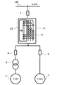
図1は、本発明の実施の形態に係る異電圧電動機駆動システムの構成を示す図である。本実施の形態に係る異電圧電動機駆動システムは、定格電圧6.6kVの電圧型インバータ10と、それにより駆動される定格電圧3.3kVの低電圧電動機1及び定格電圧6.6kVの高電圧電動機2とを備える。電圧型インバータ10は入力変圧器一体型であり、入力変圧器20と多数のセルインバータ11とを内蔵している。低電圧電動機1と高電圧電動機2とは、電圧型インバータ10に並列に接続されている。
FIG. 1 is a diagram showing a configuration of a different voltage electric motor drive system according to an embodiment of the present invention. The different voltage motor drive system according to the present embodiment includes a
本実施の形態では、電圧型インバータ10と、低電圧電動機1及び高電圧電動機2とは、電動機切替装置40を介して接続されている。電動機切替装置40は、電圧型インバータ10と低電圧電動機1との間に設けられた切替遮断器41と、電圧型インバータ10と高電圧電動機2との間に設けられた切替遮断器42とを備える。電動機切替装置40は、2つの切替遮断器41,42の何れか一方を投入しているときには他方を遮断するインターロック機構(図示略)を備えている。本実施の形態では、電圧型インバータ10と低電圧電動機1との間に出力変圧器は設けられていない。
In the present embodiment, the
本実施の形態では、電圧型インバータ10の入力変圧器20と電力系統100とを接続するラインは2つ設けられ、それぞれのラインに上位遮断器31,32が設けられている。2つの上位遮断器31,32はタップ切替装置30を構成する。タップ切替装置30は、2つの上位遮断器31,32の何れか一方を投入しているときには他方を遮断するインターロック機構(図示略)を備えている。電動機切替装置40とタップ切替装置30とは、その切替動作を連動させることができる。
In the present embodiment, two lines connecting the
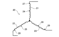
図2は、入力変圧器20の一次巻線結線図である。入力変圧器20は3つの一次巻線21,22,23を備える。各一次巻線21,22,23の中央部付近には高電圧出力用タップ24,25,26が設けられている。上位遮断器32が投入されたときには、高電圧出力用タップ24,25,26に電力系統100が接続される。また、各一次巻線21,22,23の端部には低電圧出力用タップ27,28,29が設けられている。上位遮断器31が投入されたときには、低電圧出力用タップ27,28,29に電力系統100が接続される。本実施の形態では、高電圧出力用タップ24,25,26に電力系統100が接続されたときには電圧型インバータ10の出力電圧は6.6kVとなり、低電圧出力用タップ27,28,29に電力系統100が接続されたときには電圧型インバータ10の出力電圧は3.3kVとなるように、入力変圧器20の巻数比が設計されている。
FIG. 2 is a primary winding connection diagram of the
上記の構成によれば、上位遮断器31を開いて上位遮断器32を投入し、且つ、切替遮断器41を開いて切替遮断器42を投入することで、電圧型インバータ10から高電圧電動機2へ、その定格電圧である6.6kVの電圧を供給することができる。また、上位遮断器32開いて上位遮断器31を投入し、且つ、切替遮断器42を開いて切替遮断器41を投入することで、電圧型インバータ10から低電圧電動機1へ、その定格電圧である3.3kVの電圧を供給することができる。つまり、本実施の形態に係る異電圧電動機駆動システムによれば、出力変圧器を用いることなく、1つの電圧型インバータ10で異なる定格電圧の電動機1,2を駆動することができる。
According to the above configuration, the
なお、電圧型インバータ10の出力電圧を3.3kVに切り替えた場合、電圧型インバータ10の内部の直流電圧も半分となる。この場合、不足電圧の保護設定によっては電圧型インバータ10がトリップすることもある。ゆえに、出力電圧を切り替えるときには、異常と誤判断されないように不足電圧の保護設定を変更することを併せて実施する。
When the output voltage of the
以上、本発明の実施の形態について説明したが、本発明は上記の実施形態に限定されず、本発明の趣旨を逸脱しない範囲において変形して実施することもできる。例えば、入力変圧器20のタップ位置や電圧型インバータ10の定格出力電圧を変更する事により、3.3kVや6.6kVだけでなく10kVや11kVなどの他の電圧も出力可能となる。また、タップ切替装置は、1つの上位遮断器と、その上位遮断器と接続するタップを高電圧出力用タップと低電圧出力用タップとで切り替える切替器とで構成してもよい。
Although the embodiments of the present invention have been described above, the present invention is not limited to the above-described embodiments, and can be modified and implemented without departing from the spirit of the present invention. For example, by changing the tap position of the
1 低電圧電動機
2 高電圧電動機
3 上位遮断器
4,5 切替遮断器
6 出力変圧器
10 電圧型インバータ
11 セルインバータ
20 入力変圧器
21,22,23 一次巻線
24,25,26 高電圧出力用タップ
27,28,29 低電圧出力用タップ
30 タップ切替装置
31,32 上位遮断器
40 電動機切替装置
41,42 切替遮断器
100 電力系統
1 Low-voltage
Claims (2)
入力変圧器が一体化された電圧型インバータと、
前記入力変圧器の一次巻線において前記複数の電動機のそれぞれの定格電圧に応じた位置に設けられた複数個のタップと、
前記電圧型インバータと接続する電動機を前記複数の電動機の間で切り替える電動機切替装置と、
電力系統と接続するタップを前記複数のタップの間で切り替えるタップ切替装置と、
を備えることを特徴とする異電圧電動機駆動システム。 With multiple motors with different rated voltages,
A voltage-type inverter with an integrated input transformer and
A plurality of taps provided at positions corresponding to the rated voltages of the plurality of electric motors in the primary winding of the input transformer, and
An electric motor switching device that switches the electric motor connected to the voltage type inverter between the plurality of electric motors, and an electric motor switching device.
A tap changer that switches the taps connected to the power system between the multiple taps, and
A different voltage electric motor drive system characterized by being equipped with.
Priority Applications (1)
| Application Number | Priority Date | Filing Date | Title |
|---|---|---|---|
| JP2017246396A JP6863268B2 (en) | 2017-12-22 | 2017-12-22 | Different voltage motor drive system |
Applications Claiming Priority (1)
| Application Number | Priority Date | Filing Date | Title |
|---|---|---|---|
| JP2017246396A JP6863268B2 (en) | 2017-12-22 | 2017-12-22 | Different voltage motor drive system |
Publications (2)
| Publication Number | Publication Date |
|---|---|
| JP2019115155A JP2019115155A (en) | 2019-07-11 |
| JP6863268B2 true JP6863268B2 (en) | 2021-04-21 |
Family
ID=67223844
Family Applications (1)
| Application Number | Title | Priority Date | Filing Date |
|---|---|---|---|
| JP2017246396A Active JP6863268B2 (en) | 2017-12-22 | 2017-12-22 | Different voltage motor drive system |
Country Status (1)
| Country | Link |
|---|---|
| JP (1) | JP6863268B2 (en) |
Family Cites Families (8)
| Publication number | Priority date | Publication date | Assignee | Title |
|---|---|---|---|---|
| JPS526927A (en) * | 1975-07-04 | 1977-01-19 | Hitachi Ltd | Transformer control device |
| JPS57153572A (en) * | 1981-03-18 | 1982-09-22 | Mitsubishi Electric Corp | Inverter device with transformer tap changer |
| JP3402949B2 (en) * | 1996-08-23 | 2003-05-06 | 三菱重工業株式会社 | Motor start / stop method by motor drive inverter device |
| JP2000172350A (en) * | 1998-12-08 | 2000-06-23 | Hitachi Ltd | Uninterruptible power supply unit and its control method |
| JP2009171684A (en) * | 2008-01-11 | 2009-07-30 | Daihen Corp | Power supply device and power supply device for arc processing |
| US8299732B2 (en) * | 2009-01-15 | 2012-10-30 | Rockwell Automation Technologies, Inc. | Power conversion system and method |
| CN106104996B (en) * | 2014-02-03 | 2019-07-05 | 约翰逊控制技术公司 | Multiple-pulse constant-voltage transformer for the variable speed drive in chiller applications |
| JP6568809B2 (en) * | 2016-01-29 | 2019-08-28 | 東芝三菱電機産業システム株式会社 | Inverter device, motor drive device, and motor drive system |
-
2017
- 2017-12-22 JP JP2017246396A patent/JP6863268B2/en active Active
Also Published As
| Publication number | Publication date |
|---|---|
| JP2019115155A (en) | 2019-07-11 |
Similar Documents
| Publication | Publication Date | Title |
|---|---|---|
| US8294408B2 (en) | Power supply with two series inverters for a polyphase electromechanical actuator | |
| US7568931B2 (en) | Integrated power cell bypass assembly and power supply including same | |
| US9220179B2 (en) | Pluggable power cell for an inverter | |
| WO2014084010A1 (en) | Power conversion device | |
| CN107921880B (en) | Vehicle-side power circuit for supplying power in an electric vehicle | |
| US20110044010A1 (en) | Pluggable power cell for an inverter | |
| US20090251009A1 (en) | Drive Isolation Transformer Controller and Method | |
| RU2007143590A (en) | PANEL CONVERTER BUILT INTO THE DISTRIBUTION BOARD | |
| JP2011193589A (en) | Power converter | |
| US9882371B2 (en) | Direct current voltage switch for switching a direct current in a branch of a direct current voltage network node | |
| US9774187B2 (en) | Coupling-in and coupling-out of power in a branch of a DC voltage network node comprising a longitudinal voltage source | |
| JP2015510268A (en) | Transformer with tap changer | |
| WO2017213030A1 (en) | Power conversion device | |
| CN110651407A (en) | Power conversion device | |
| AU2014252950B2 (en) | Transformer provided with means for adjusting the in-load transformation ratio | |
| JP6863268B2 (en) | Different voltage motor drive system | |
| CN105684115B (en) | Switchgear with pre-selector | |
| JP6889013B2 (en) | Power converters and distributed power systems | |
| DK2994984T3 (en) | The three-point converter | |
| US20160380570A1 (en) | Motor control center including an integrated dual bus configuration | |
| US7573153B2 (en) | Power supply apparatus for field devices | |
| US2245342A (en) | Electric control system | |
| WO2011024668A1 (en) | Engine system | |
| JP5575424B2 (en) | Synchronous generator | |
| JP2008043017A (en) | Kondorfer starting device for electric motor |
Legal Events
| Date | Code | Title | Description |
|---|---|---|---|
| A621 | Written request for application examination |
Free format text: JAPANESE INTERMEDIATE CODE: A621 Effective date: 20191209 |
|
| A977 | Report on retrieval |
Free format text: JAPANESE INTERMEDIATE CODE: A971007 Effective date: 20201028 |
|
| A131 | Notification of reasons for refusal |
Free format text: JAPANESE INTERMEDIATE CODE: A131 Effective date: 20201104 |
|
| TRDD | Decision of grant or rejection written | ||
| A01 | Written decision to grant a patent or to grant a registration (utility model) |
Free format text: JAPANESE INTERMEDIATE CODE: A01 Effective date: 20210302 |
|
| A61 | First payment of annual fees (during grant procedure) |
Free format text: JAPANESE INTERMEDIATE CODE: A61 Effective date: 20210315 |
|
| R150 | Certificate of patent or registration of utility model |
Ref document number: 6863268 Country of ref document: JP Free format text: JAPANESE INTERMEDIATE CODE: R150 |
|
| R250 | Receipt of annual fees |
Free format text: JAPANESE INTERMEDIATE CODE: R250 |