JP6861435B2 - Water stop device - Google Patents
Water stop device Download PDFInfo
- Publication number
- JP6861435B2 JP6861435B2 JP2018072170A JP2018072170A JP6861435B2 JP 6861435 B2 JP6861435 B2 JP 6861435B2 JP 2018072170 A JP2018072170 A JP 2018072170A JP 2018072170 A JP2018072170 A JP 2018072170A JP 6861435 B2 JP6861435 B2 JP 6861435B2
- Authority
- JP
- Japan
- Prior art keywords
- balloon
- end portion
- central axis
- core rod
- fixture
- Prior art date
- Legal status (The legal status is an assumption and is not a legal conclusion. Google has not performed a legal analysis and makes no representation as to the accuracy of the status listed.)
- Active
Links
Images


Landscapes
- Pipe Accessories (AREA)
- Sealing Devices (AREA)
Description
本発明は、管体内に挿入されて当該管体の途中を閉塞するために用いられる止水装置に関する。 The present invention relates to a water blocking device that is inserted into a tube and used to block the middle of the tube.
例えば特許文献1には、配管工事用バルーンが記載されている。このバルーンは、管状芯金の外周にゴム材からなるバルーン本体を取り付け、このバルーン本体内に給気管から圧力空気を送入してバルーン本体を膨張させることにより、配管内を2つに隔絶するようになっている。
For example,
また、特許文献2には、水路管の流水を止める止水具が記載されている。この止水具は、弾性袋状体の中心に排水管が挿通されており、前記弾性袋状体内に給排弁から空気を充填して膨張させることにより、当該弾性袋状体の外周の円弧状外面を前記水路管の内周面に弾接させて、前記水路管を閉塞するようになっている。
Further,
さらに、特許文献3には、ガス工事用の耐熱性パッカーが記載されている。このパッカーは、パッカー本体に挿通される案内部材の内部から供給される冷却水または圧縮空気をパッカー本体内部に充填することにより、ガス管の途中を閉塞するようになっている。
Further,
上記特許文献1〜3では、前記バルーン本体、前記弾性袋状体ならびに前記パッカー本体がゴム等の弾性体で形成されているだけであるために、使用環境によっては耐圧性が不足することが懸念される。
In
また、上記特許文献1〜3では、前記バルーン本体、前記弾性袋状体ならびに前記パッカー本体を膨張させる際、それらの両端がそれらの中心に配置される部材(前記管状芯金、前記排水管ならびに前記案内部材)の軸方向に膨らまないように規制されている関係より、非膨張時の径方向寸法が大きく設定されている。
Further, in
そのために、非膨張時には前記バルーン本体、前記弾性袋状体ならびに前記パッカー本体をその使用対象となる管体(前記配管、前記水路管ならびに前記ガス管)の内部に挿入可能とするように径方向内向きにコンパクトに折り畳む必要があり、また、その際に膨張しやすくするように折り畳み形態を工夫する必要がある。 Therefore, in the radial direction, the balloon body, the elastic bag-like body, and the packer body can be inserted into the pipe body (the pipe, the water channel pipe, and the gas pipe) to be used when not inflated. It is necessary to fold it compactly inward, and it is necessary to devise a folding form so that it can be easily expanded at that time.
このような事情に鑑み、本発明は、管体内に挿入されて当該管体の途中を閉塞するために用いられる止水装置において、耐圧性に優れかつ非膨張時に前記管体へ挿入しやすくしたうえでバルーンをスムースに膨張可能とすることを目的としている。 In view of such circumstances, the present invention makes it easy to insert into the pipe body when it is not inflated and has excellent pressure resistance in a water stop device which is inserted into the pipe body and used to close the middle of the pipe body. The purpose is to make the balloon inflatable smoothly.
本発明は、管体内に挿入されて当該管体の途中を閉塞するために用いられる止水装置であって、筒状で中心軸線方向の中間部分が一端部分および他端部分よりも大径とされた弾性伸縮可能なバルーンと、このバルーンの中心軸線方向全域に挿入されかつ内部に前記バルーン内に加圧気体を供給するための給気路を有する芯棒と、前記バルーンの一端部分の外径側に嵌合されることにより当該一端部分を前記芯棒の外周面における中心軸線方向の一端側に圧接させて中心軸線方向に不動に固定するための第1固定具と、前記芯棒の外周面における中心軸線方向の他端側に中心軸線方向に摺動変位可能に嵌合されるスライドスリーブと、このスライドスリーブと前記芯棒との嵌め合い面を気密にするシールリングと、前記バルーンの他端部分の外径側に嵌合されることにより当該他端部分を前記スライドスリーブの外周面に圧接させてその中心軸線方向に不動に固定するための第2固定具と、を備え、前記第1、第2固定具の外径は、止水対象となる管体に対する止水装置の出し入れ口の内径よりも小さく設定されており、前記バルーンの中心軸線方向の中間部分の非膨張時における外径は、前記第1、第2固定具の外径と同等以下に設定されており、前記バルーンの内部には、その中心軸線方向に沿って延在するとともに円周方向の複数ヶ所に補強線材が埋設されている、ことを特徴としている。 The present invention is a water blocking device that is inserted into a tube and used to close the middle of the tube, and has a tubular shape with an intermediate portion in the central axis direction having a larger diameter than one end portion and the other end portion. An elastically stretchable balloon, a core rod inserted in the entire central axis direction of the balloon and having an air supply path inside for supplying pressurized gas into the balloon, and outside one end portion of the balloon. A first fixture for pressing one end portion of the outer peripheral surface of the core rod to one end side in the central axis direction and immovably fixing the core rod in the direction of the central axis by being fitted on the diameter side, and the core rod. A slide sleeve that is slidably and displaceably fitted to the other end side of the outer peripheral surface in the central axis direction, a seal ring that makes the fitting surface between the slide sleeve and the core rod airtight, and the balloon. A second fixture for pressing the other end portion against the outer peripheral surface of the slide sleeve and immovably fixing the other end portion in the central axis direction by being fitted to the outer diameter side of the other end portion of the slide sleeve is provided. The outer diameter of the first and second fixtures is set to be smaller than the inner diameter of the entrance / exit of the water stop device with respect to the pipe body to be stopped, and when the intermediate portion in the central axis direction of the balloon is not inflated. The outer diameter of the first and second fixtures is set to be equal to or less than the outer diameter of the first and second fixtures, and the inside of the balloon extends along the central axis direction and is located at a plurality of locations in the circumferential direction. reinforcement wires are embedded, it is characterized in that.
この構成では、バルーンの膨張前の径方向寸法を過剰に大きくすることなく、止水装置を前記止水対象となる管体内へ比較的容易に挿入することが可能になる。 In this configuration, the water blocking device can be relatively easily inserted into the tube body to be water-stopped without excessively increasing the radial dimension of the balloon before expansion.
しかも、上記構成では、前記バルーンを補強線材で補強しているから、当該バルーンの肉厚を薄くしながらも耐圧性を確保することが可能になる。そのため、本発明に係る止水装置は止水対象となる管体(水等の液体を貯留するタンクの排水管等)を一時的に閉塞する際に好適に利用できるようになる。 Moreover, in the above configuration, since the balloon is reinforced with a reinforcing wire, it is possible to secure pressure resistance while reducing the wall thickness of the balloon. Therefore, the water stop device according to the present invention can be suitably used when temporarily closing a pipe body (such as a drain pipe of a tank for storing a liquid such as water) to be stopped.
また、本発明に係る止水装置では、前記バルーン内に加圧気体を供給する過程において、前記スライドスリーブに固定される他端部分が前記第1固定具により前記芯棒に対して固定される一端部分へ向けて摺動変位することになって、前記バルーンの中間部分がスムースに径方向外向きに膨らむことになる。 Further, in the water stop device according to the present invention, in the process of supplying the pressurized gas into the balloon, the other end portion fixed to the slide sleeve is fixed to the core rod by the first fixture. The sliding displacement toward one end portion causes the intermediate portion of the balloon to smoothly bulge outward in the radial direction.
これにより、前記一端部分および前記他端部分に応力が集中しにくくなる他、前記中間部分の伸張量が軽減されることになるので、前記バルーンの耐久性が向上する。 As a result, stress is less likely to be concentrated on the one end portion and the other end portion, and the amount of extension of the intermediate portion is reduced, so that the durability of the balloon is improved.
また、上記止水装置は、前記止水対象となる管体の上向き開口内に前記第2固定具を下にするとともに前記第1固定具を上にした姿勢で吊り下げて挿入されることにより使用されるものであって、前記第1固定具には、前記止水対象となる管体の上向き開口の周縁に上側から引っ掛けられるストッパ部材が取り付けられている、ことが好ましい。 Further, the water stop device is inserted by suspending and inserting the second fixture in an upward opening of the pipe body to be stopped, with the second fixture facing down and the first fixture facing up. It is preferable that the first fixture is attached with a stopper member that is hooked from above on the peripheral edge of the upward opening of the pipe body to be water-stopped.
この構成では、本発明に係る止水装置を前記止水対象となる管体に対して簡易に使用できるようになる。 With this configuration, the water stop device according to the present invention can be easily used for the pipe body to be stopped.
また、上記止水装置において、前記バルーンは、径方向に積層される二層構造とされ、その内径側の層がガス非透過性に優れた材料とされ、外径側の層が耐候性に優れた材料とされている、ことが好ましい。 Further, in the water blocking device, the balloon has a two-layer structure in which the balloons are laminated in the radial direction, the inner diameter side layer is made of a material having excellent gas impermeable property, and the outer diameter side layer is weather resistant. It is preferable that it is an excellent material.
このように、本発明の前記二層構造のバルーンによれば、前記加圧気体の透過を防止できるようになって、しかも前記管体の内周面に圧接することによって当該内周面を経時的に汚染することを防止できるようになる。 As described above, according to the balloon having the two-layer structure of the present invention, the permeation of the pressurized gas can be prevented, and the inner peripheral surface is pressed against the inner peripheral surface of the tubular body over time. It becomes possible to prevent the contamination.
また、上記止水装置において、前記バルーンの中間部分の肉厚は、他領域に比べて薄く設定されている、ことが好ましい。 Further, in the water blocking device, it is preferable that the wall thickness of the intermediate portion of the balloon is set thinner than that of other regions.
この構成では、前記バルーン内に供給される加圧気体の圧力を可及的に低くしても前記バルーンの中間部分が膨張しやすくなる。これにより、前記バルーンの膨張時における作動性が良好になる。 In this configuration, even if the pressure of the pressurized gas supplied into the balloon is lowered as much as possible, the intermediate portion of the balloon is likely to expand. This improves the operability of the balloon when it is inflated.
さらに、上記止水装置において、前記バルーンの一端部分および他端部分の肉厚は、それぞれ端縁へ向けて漸次厚くされている、ことが好ましい。 Further, in the water blocking device, it is preferable that the wall thickness of one end portion and the other end portion of the balloon is gradually increased toward the end edge, respectively.
この構成では、前記バルーンの膨張時において前記芯棒に対する固定強度が向上することになる。これにより、前記バルーンの膨張時の耐圧性が向上する。 In this configuration, the fixing strength to the core rod is improved when the balloon is inflated. This improves the pressure resistance of the balloon when it is inflated.
本発明に係る止水装置は、耐圧性に優れかつ非膨張時に止水対象となる管体へ挿入しやすくしたうえでバルーンをスムースに膨張することが可能になる。 The water blocking device according to the present invention has excellent pressure resistance and can easily inflate the balloon after being easily inserted into the pipe body to be stopped when not inflated.
以下、本発明を実施するための最良の実施形態について添付図面を参照して詳細に説明する。 Hereinafter, the best embodiment for carrying out the present invention will be described in detail with reference to the accompanying drawings.
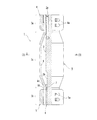
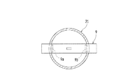
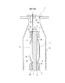
図1から図11に本発明の一実施形態を示している。図中、1は止水装置の全体を示している。 1 to 11 show an embodiment of the present invention. In the figure, 1 indicates the entire water stop device.
止水装置1は、芯棒2、バルーン3、第1固定具4、第2固定具5、スライドスリーブ6等を備えている。
The
芯棒2は、中実の丸棒部材とされている。この芯棒2の内部には、バルーン3内に加圧気体(例えば空気)を供給するための給気路2aが設けられている。この給気路2aは、芯棒2の軸方向一端側から軸方向中間部分の所定位置で径方向外向きに開放するように設けられている。
The
この芯棒2の軸方向他端側は他の領域よりも小径に形成されている。この小径部に符号2bを付している。また、芯棒2の軸方向一端側の所定位置には、径方向外向きに突出するとともに円周方向に連続する輪状凸部2cが設けられている。この輪状凸部2cは、下記するバルーン3の一端部分3aを第1固定具4で固定する際に当該固定強度を高めるために設けられている。
The other end side of the
このような芯棒2は、例えば適宜の金属材あるいは所定の強度を有する合成樹脂等で形成されている。
Such a
バルーン3は、弾性伸縮可能な弾性材料で形成されていて、膨張前の形状が円筒状とされかつその中心軸線方向の中間部分3cが一端部分3aおよび他端部分3bよりも大径とされている。
The
このバルーン3は、例えば単一の弾性材料で形成されている。この弾性材料としては、例えばクロロプレンゴム(CR)、スチレンブタジエンゴム(SBR)、ニトリルブタジエンゴム(NBR)等、あるいはエチレン・プロピレンコゴム(EPDM)、シリコンゴム(SI)等が挙げられる。
The
このバルーン3の内部には、その中心軸線方向に沿って延在するとともに円周方向の複数ヶ所に補強部材8が埋設されている。
Inside the
この補強線材8としては、適宜の金属材料あるいは化学繊維(ポリアミド系、ポリエステル系)等が挙げられる。この補強線材8は、バルーン3の成形時に金型内にインサートして成形する形態とすることが好ましい。この成形時には、多数の補強線材8の相対的な位置決めとばらけ防止とを図るために、図示していないが、当該多数の補強線材8を円周方向に沿う横線でもって束ねるようにすることが好ましい。
Examples of the reinforcing
第1固定具4は、バルーン3の一端部分3aの外径側に嵌合されることにより当該一端部分3aを芯棒2の外周面における中心軸線方向の一端側に圧接させて中心軸線方向に不動に固定する。
The
第2固定具5は、バルーン3の他端部分3bの外径側に嵌合されることにより当該他端部分3bをスライドスリーブ6の外周面に圧接させてその中心軸線方向に不動に固定する。
The
スライドスリーブ6は、芯棒2の外周面における中心軸線方向の他端側の小径部2bに摺動変位可能となるように嵌合(例えばすきま嵌め)されている。このスライドスリーブ6の外径側には、前記したように第2固定具5を用いることによりバルーン3の他端側が嵌合されて固定されるようになっている。
The
なお、スライドスリーブ6の肉厚は、芯棒2における小径部2bとその他の部分との外径寸法の差と同一あるいは略同一に設定されている。これにより、芯棒2の小径部2bにスライドスリーブ6を嵌合した状態においてスライドスリーブ6の外周面が芯棒2において小径部2b以外の部分の外周面に面一あるいは略面一になる。
The wall thickness of the
また、スライドスリーブ6の軸方向一端側(内端側)には、径方向外向きに張り出す輪状凸部6aが設けられている。
Further, on one end side (inner end side) of the
この輪状凸部6aは、バルーン3を膨張させる際にスライドスリーブ6の最大スライド位置を規制するためと、バルーン3の位置決めおよび抜け止めのために設けられている。つまり、スライドスリーブ6がスライドさせられる過程において、輪状凸部6aが芯棒2において小径部2bとその他の領域との間の段壁面に当接すると、当該スライドスリーブ6のスライドが強制的に停止されることになる。また、輪状凸部6aと第2固定具5とでバルーン3の他端部分3aの位置決めと抜け止めとを行うことによって固定強度を高めることができるようになる。
The ring-shaped
さらに、スライドスリーブ6の内周面において軸方向一端側(内端側)には、周溝6bが形成されている。この周溝6b内には、Oリング等のシールリング7が径方向内向きにはみ出すような状態で装着されている。このシールリング7は、スライドスリーブ6と芯棒2との嵌め合い面を気密にする。
Further, on the inner peripheral surface of the
このスライドスリーブ6を例えば摩擦抵抗を軽減する材料で形成するか、あるいはスライドスリーブ6を適宜の金属材料あるいは所定の強度を有する合成樹脂で形成し、その内周面に摩擦抵抗を軽減する材料をコーティングすることが好ましい。
The
そのようにすれば、バルーン3を膨張させる際、バルーン3が膨張するに従い当該バルーン3の他端部分3bがスライドスリーブ6と共に芯棒2に対して一端部分3aへ向けてスムースに摺動変位するようになるので、バルーン3を容易に膨張させることが可能になる。
Then, when the
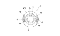
ところで、第1、第2固定具4,5は、二分割構造とされていて、その片方半円部材には連結ボルト4a,5aの挿通孔4b,5bが設けられており、他方半円部材には連結ボルト4a,5aが螺合されるねじ孔4c,5cが設けられている。
By the way, the first and
つまり、第1、第2固定具4,5は、バルーン3の一端部分3aと他端部分3bとに径方向外側から径方向内向きに締め付けられることによってバルーン3の一端部分3aを芯棒2に、また、バルーン3の他端部分3bをスライドスリーブ6にそれぞれ固定するために用いられる。
That is, the first and
また、第1、第2固定具4,5の外径は、止水対象となる管体(例えば図5の第1配管21、第2配管22)の上向き開口(タンク20に対する接続端部)の内径よりも小さく設定されていて、バルーン3において中心軸線方向の中間部分3cの非膨張時における外径は、第1、第2固定具4,5の外径と同等以下に設定されている。なお、前記第1配管21、第2配管22)の上向き開口は、止水装置1の出し入れ口に相当する。
Further, the outer diameters of the first and
さらに、バルーン3において中心軸線方向の中間部分3cの膨張時における外径は、止水対象となる管体(例えば図5の第1配管21、第2配管22)の内径よりも大きくなるように設定されている。
Further, in the
次に、上記構成の止水装置1の使用形態について説明する。
Next, a usage mode of the
止水装置1の使用対象としては、例えば図5に示すような適宜のプラントのタンク20が挙げられる。
Examples of the target of use of the
このタンク20の底部には、2つの管体(第1配管21、第2配管22)が接続されている。第1、第2配管21,22の先端側には、図示していないが、タンク20内の液体が供給される適宜の機器が接続されている。第1配管21の途中には、その内部通路の開度を制御するためのバルブ23が設けられている。
Two pipe bodies (
ここで、タンク20内の液体を抜かずに第1配管21のバルブ23を交換または補修する際、あるいはタンク20内の液体を抜かずに第2配管22を交換または補修する際に、止水装置1を用いる。
Here, when replacing or repairing the
具体的に、例えば図1または図10に示すように、第1、第2配管21,22の上向き開口(タンク20に対する接続端部)から止水装置1を挿入する。
Specifically, for example, as shown in FIG. 1 or FIG. 10, the
このとき、止水装置1の芯棒2の軸方向一端側にワイヤ10および取付具11を介してストッパ部材9を取り付ける。
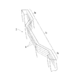
At this time, the
このストッパ部材9は、図7に示すように、帯板状に形成されており、この全長寸法が第1、第2配管21,22の上向き開口の内径寸法よりも大きく設定されている。このストッパ部材9を第1、第2配管21,22の上向き開口に引っ掛けた状態で位置ずれを防止するために、ストッパ部材9の片面において長手方向両端には突片9a,9bが設けられている。なお、このストッパ部材9は、予め止水装置1の芯棒2に取り付けておくことも可能である。
As shown in FIG. 7, the
つまり、この止水装置1を挿入する際には第2固定具5を下にするとともに第1固定具4を上にした姿勢で挿入し、ストッパ部材9を第1、第2配管21,22の上向き開口に引っ掛けるようにすれば、止水装置1を吊り下げた状態に保持できるようになる。
That is, when inserting the
ところで、第1配管21の上向き開口は内径寸法が均一な直管形状になっているが、第2配管22の上向き開口は内径寸法が端縁から離れるに従い漸次拡径するようなテーパ形状になっている。
By the way, the upward opening of the
このような第2配管22に挿入する止水装置1については、その外径寸法を第2配管22の上向き開口の端縁の内径寸法よりも僅かに小さく設定することが好ましい。さらに、例えば第1、第2配管21,22に止水装置1を挿入する過程でタンク内の水圧によってバルーン3が縮径して芯棒2の外周面に密着することがあるが、その際に当該縮径した部分の外径寸法が第1、第2配管21,22の上向き開口の内径寸法よりも僅かに小さくなるように設定することが好ましい。
It is preferable that the outer diameter of the
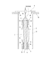
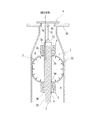
そして、前記のように第1、第2配管21,22の上向き開口に止水装置1を挿入した後、止水装置1のバルーン3に給気路2aから加圧気体(空気)を供給することにより、図8、図9ならびに図11に示すように、バルーン3を膨張させて当該バルーン3の外周面を第1、第2配管21,22の内周面に圧接させるようにする。
Then, after inserting the
これにより、第1、第2配管21,22の上向き開口が閉塞されることになり、タンク20内の液体が外に漏れ出ることが防止される。そのため、バルブ23の交換または補修等を含む保守点検作業や、第2配管22の交換または補修等を含む保守点検作業を容易に行えるようになる。
As a result, the upward openings of the first and
以上説明したように本発明を適用した実施形態によれば、バルーン3の膨張前の径方向寸法を過剰に大きくすることなく、止水装置1を止水対象となる管体(第1配管21、第2配管22)内へ比較的容易に挿入することが可能になる。
As described above, according to the embodiment to which the present invention is applied, the
また、バルーン3を補強線材8で補強しているから、当該バルーン3の肉厚を薄くしながらも耐圧性を確保することが可能になる。そのため、本発明に係る止水装置1は止水対象となる管体(第1配管21、第2配管22)を一時的に閉塞する際に好適に利用できるようになる。
Further, since the
また、本発明に係る止水装置1では、バルーン3内に加圧気体を供給する過程において、スライドスリーブ6に固定されるバルーン3の他端部分3bが第1固定具4により芯棒2に対して固定されるバルーン3の一端部分3aへ向けて摺動変位することになって、バルーン3の中間部分3cがスムースに径方向外向きに膨らむことになる。
Further, in the
これにより、バルーン3の一端部分3aおよび他端部分3bに応力が集中しにくくなる他、バルーン3の中間部分3cの伸張量が軽減されることになるので、バルーン3の耐久性が向上する。
As a result, stress is less likely to be concentrated on one
なお、本発明は、上記実施形態のみに限定されるものではなく、特許請求の範囲内および当該範囲と均等の範囲内で適宜に変更することが可能である。 The present invention is not limited to the above embodiment, and can be appropriately modified within the scope of claims and within the scope equivalent to the scope.
(1)上記実施形態では、バルーン3の肉厚をその中心軸線方向全域にわたって均一に設定した例を挙げているが、本発明はこれのみに限定されるものではない。
(1) In the above embodiment, an example in which the wall thickness of the
例えば図示していないが、バルーン3の中間部分3cの肉厚を他領域に比べて薄く設定することが可能である。
For example, although not shown, the wall thickness of the
この場合、バルーン3内に供給される加圧気体の圧力を可及的に低くしてもバルーン3の中間部分3cが膨張しやすくなる。これにより、バルーン3の膨張時における作動性が良好になる。
In this case, even if the pressure of the pressurized gas supplied into the
また、例えば図示していないが、バルーン3の一端部分3aおよび他端部分3bの肉厚をそれぞれ端縁へ向けて漸次厚くすることが可能である。
Further, for example, although not shown, the wall thickness of one
この場合、バルーン3の膨張時において芯棒2に対する固定強度が向上することになる。これにより、バルーン3の膨張時の耐圧性が向上する。
In this case, the fixing strength to the
(2)上記実施形態では、バルーン3を一層構造とした例を挙げているが、本発明はこれのみに限定されるものではなく、例えばバルーン3を二層構造とすることが可能である。
(2) In the above embodiment, an example in which the
具体的に、バルーン3を二層構造とする場合には、その内径側の層をガス非透過性に優れた材料(例えば前記CR、SBR、NBR等の汎用ゴム類)とし、外径側の層を耐候性に優れた材料(例えば前記EPDM、SI等)とすることが好ましい。
Specifically, when the
このようにバルーン3を二層構造にすれば、バルーン3の前記内径側の層が当該バルーン3内に供給する加圧気体が外側に透過することを防止し、また、バルーン3の前記外径側の層が第1、第2配管21,22の内周面に圧接することによって当該内周面を経時的に汚染することを防止する。これにより、バルーン3の使用環境が制限されずに済む等、使い勝手が向上する。
When the
(3)上記実施形態において、バルーン3の内部において補強線材8を径方向に2つあるいはそれ以上離隔して埋設することが可能である。
(3) In the above embodiment, it is possible to bury two or more reinforcing
この場合には、バルーン3の一端部分3aおよび他端部分3bの剛性がさらに向上することになり、バルーン3の耐圧性のさらなる向上に貢献できる。
In this case, the rigidity of one
(4)上記実施形態では、バルーン3を膨張前の形状を円筒状とした例を挙げているが、本発明はこれのみに限定されるものではなく、例えば図示していないが、バルーン3の膨張前の形状は角筒状あるいは楕円筒状等とすることが可能である。
(4) In the above embodiment, an example in which the shape of the
(5)上記実施形態では、止水装置1の芯棒2の軸方向一端側にワイヤ10および取付具11を介してストッパ部材9を取り付けるようにして第1固定具4を上にするとともに第2固定具5を下にした姿勢で第1、第2配管21,22内に挿入する形態とする例を挙げているが、本発明はこれのみに限定されるものではない。
(5) In the above embodiment, the
例えば図示していないが、止水装置1の芯棒2の軸方向他端側にワイヤ10および取付具11を介してストッパ部材9を取り付けるようにして第2固定具5を上にするとともに第1固定具4を下にした姿勢で第1、第2配管21,22内に挿入する形態とすることも可能である。
For example, although not shown, the
(6)上記実施形態では、芯棒2を中実にした例を挙げているが、本発明はこれのみに限定されるものではなく、例えば図12に示すように、芯棒2の中心に中空部分を形成することも可能である。
(6) In the above embodiment, an example in which the
(7)上記実施形態では、芯棒2の外形を円形にした例を挙げているが、本発明はこれのみに限定されるものではなく、例えば図示していないが芯棒2の外形を多角形あるいは楕円形等とすることも可能である。
(7) In the above embodiment, an example in which the outer shape of the
(8)上記実施形態では、芯棒2の軸方向一端側から軸方向中間部分までの領域の外径を一定にした例を挙げているが、本発明はこれのみに限定されるものではない。
(8) In the above embodiment, an example in which the outer diameter of the region from one end side in the axial direction of the
例えば図13に示すように、芯棒2の軸方向中間部分の外径寸法を軸方向一端側および軸方向他端側の外形寸法よりも小さく設定することが可能である。
For example, as shown in FIG. 13, the outer diameter dimension of the axially intermediate portion of the
(9)上記実施形態では、芯棒2をワンピース構造にした例を挙げているが、本発明はこれのみに限定されるものではない。
(9) In the above embodiment, an example in which the
また、例えば図14に示すように、芯棒2を任意数(例えば3つ)の部材(第1短尺丸棒部材2A,第2短尺丸棒部材2B,連結シャフト2C、固定ナット2D)を組み合わせた構成することが可能である。
Further, for example, as shown in FIG. 14, the
なお、第1短尺丸棒部材2Aの軸方向途中には、第1固定具4によるバルーン3の固定強度を高めるために輪状凸部2cが設けられている。第2短尺丸棒部材2Bの内端には、バルーン3の膨張時においてスライドスリーブ6のスライドストロークを規制するため、
ならびに第2固定具5によるバルーン3の固定強度を高めるために輪状凸部2Eが設けられている。第2短尺丸棒部材2Bの外径寸法は第1短尺丸棒部材2Aの外径寸法よりも適宜小さく設定されている。
A ring-shaped
Further, a ring-shaped
本発明は、管体内に挿入されて当該管体の途中を閉塞するために用いられる止水装置に好適に利用することが可能である。 INDUSTRIAL APPLICABILITY The present invention can be suitably used for a water stop device which is inserted into a pipe body and used to close the middle of the pipe body.
1 止水装置
2 芯棒
2a 給気路
3 バルーン
3a 一端部分
3b 他端部分
3c 中間部分
4 第1固定具
5 第2固定具
6 スライドスリーブ
7 シールリング
8 補強線材
9 ストッパ部材
10 ワイヤ
11 取付具
20 タンク
21 第1配管
22 第2配管
23 バルブ
1 Water stop
2a
3a One end
3b The other end
Claims (5)
筒状で中心軸線方向の中間部分が一端部分および他端部分よりも大径とされた弾性伸縮可能なバルーンと、
このバルーンの中心軸線方向全域に挿入されかつ内部に前記バルーン内に加圧気体を供給するための給気路を有する芯棒と、
前記バルーンの一端部分の外径側に嵌合されることにより当該一端部分を前記芯棒の外周面における中心軸線方向の一端側に圧接させて中心軸線方向に不動に固定するための第1固定具と、
前記芯棒の外周面における中心軸線方向の他端側に中心軸線方向に摺動変位可能に嵌合されるスライドスリーブと、
このスライドスリーブと前記芯棒との嵌め合い面を気密にするシールリングと、
前記バルーンの他端部分の外径側に嵌合されることにより当該他端部分を前記スライドスリーブの外周面に圧接させてその中心軸線方向に不動に固定するための第2固定具と、を備え、
前記第1、第2固定具の外径は、止水対象となる管体に対する止水装置の出し入れ口の内径よりも小さく設定されており、
前記バルーンの中心軸線方向の中間部分の非膨張時における外径は、前記第1、第2固定具の外径と同等以下に設定されており、
前記バルーンの内部には、その中心軸線方向に沿って延在するとともに円周方向の複数ヶ所に補強線材が埋設されている、ことを特徴とする止水装置。 A water stop device that is inserted into the tube and used to block the middle of the tube.
An elastically stretchable balloon with a tubular shape and an intermediate portion in the central axis direction having a diameter larger than that of one end portion and the other end portion.
A core rod inserted in the entire central axis direction of the balloon and having an air supply passage for supplying pressurized gas into the balloon inside.
First fixing for immovably fixing the one end portion in the central axis direction by being fitted to the outer diameter side of the one end portion of the balloon so that the one end portion is pressed against one end side in the central axis direction on the outer peripheral surface of the core rod. Ingredients and
A slide sleeve that is fitted to the other end side of the outer peripheral surface of the core rod in the direction of the central axis so as to be slidable and displaceable in the direction of the central axis.
A seal ring that makes the fitting surface between the slide sleeve and the core rod airtight,
A second fixture for pressing the other end portion against the outer peripheral surface of the slide sleeve and immovably fixing the other end portion in the central axis direction by being fitted to the outer diameter side of the other end portion of the balloon. Prepare,
The outer diameter of the first and second fixtures is set to be smaller than the inner diameter of the inlet / outlet of the water stop device for the pipe body to be stopped.
The outer diameter of the middle portion in the central axis direction of the balloon when not inflated is set to be equal to or less than the outer diameter of the first and second fixtures.
Inside of the balloon, waterproofing device for its well as extending along the central axis line direction reinforcement wires in several places in the circumferential direction are embedded, the said.
前記第1固定具には、前記止水対象となる管体の上向き開口の周縁に上側から引っ掛けられるストッパ部材が取り付けられている、ことを特徴とする止水装置。 The water blocking device according to claim 1 is inserted by suspending and inserting the second fixture in an upward opening of the pipe body to be water-stopped with the second fixture facing down and the first fixture facing up. It is used by
The first fixture is characterized in that a stopper member hooked from above is attached to the peripheral edge of the upward opening of the pipe body to be water-stopped.
前記バルーンは、径方向に積層される二層構造とされ、その内径側の層がガス非透過性に優れた材料とされ、外径側の層が耐候性に優れた材料とされている、ことを特徴とする止水装置。 In the water blocking device according to claim 1 or 2.
The balloon has a two-layer structure laminated in the radial direction, the inner diameter side layer is made of a material having excellent gas impermeable properties, and the outer diameter side layer is made of a material having excellent weather resistance. A water stop device characterized by that.
前記バルーンの中間部分の肉厚は、他領域に比べて薄く設定されている、ことを特徴とする止水装置。 In the water blocking device according to any one of claims 1 to 3.
A water blocking device characterized in that the wall thickness of the intermediate portion of the balloon is set thinner than that of other regions.
前記バルーンの一端部分および他端部分の肉厚は、それぞれ端縁へ向けて漸次厚くされている、ことを特徴とする止水装置。 In the water blocking device according to any one of claims 1 to 4.
A water blocking device characterized in that the wall thickness of one end portion and the other end portion of the balloon is gradually increased toward the end edge, respectively.
Priority Applications (1)
| Application Number | Priority Date | Filing Date | Title |
|---|---|---|---|
| JP2018072170A JP6861435B2 (en) | 2018-04-04 | 2018-04-04 | Water stop device |
Applications Claiming Priority (1)
| Application Number | Priority Date | Filing Date | Title |
|---|---|---|---|
| JP2018072170A JP6861435B2 (en) | 2018-04-04 | 2018-04-04 | Water stop device |
Publications (2)
| Publication Number | Publication Date |
|---|---|
| JP2019183886A JP2019183886A (en) | 2019-10-24 |
| JP6861435B2 true JP6861435B2 (en) | 2021-04-21 |
Family
ID=68340409
Family Applications (1)
| Application Number | Title | Priority Date | Filing Date |
|---|---|---|---|
| JP2018072170A Active JP6861435B2 (en) | 2018-04-04 | 2018-04-04 | Water stop device |
Country Status (1)
| Country | Link |
|---|---|
| JP (1) | JP6861435B2 (en) |
Families Citing this family (4)
| Publication number | Priority date | Publication date | Assignee | Title |
|---|---|---|---|---|
| CN111395497A (en) * | 2020-03-25 | 2020-07-10 | 中国建筑第八工程局有限公司 | Temporary flow guiding method and structure for existing drainage pipe in case of damage of excavated groove |
| CN114412995A (en) * | 2021-12-17 | 2022-04-29 | 南京博丞橡塑有限公司 | Rubber seal and method for manufacturing same |
| CN114232995B (en) * | 2021-12-31 | 2023-05-05 | 歌山建设集团有限公司 | Water stop screw rod assembly and construction method thereof |
| CN119572860A (en) * | 2025-02-08 | 2025-03-07 | 济南汇通热力有限公司 | A waterproof and dustproof quick plugging device for the port of a direct-buried prefabricated thermal insulation pipe |
Family Cites Families (5)
| Publication number | Priority date | Publication date | Assignee | Title |
|---|---|---|---|---|
| NL9101900A (en) * | 1991-11-14 | 1993-06-01 | Beugen J Van Beheer Bv | METHOD FOR MANUFACTURING AN INFLATABLE CONNECTION PLUG FOR PIPES |
| JP2578479Y2 (en) * | 1993-03-11 | 1998-08-13 | 大阪瓦斯株式会社 | Fluid isolation bag |
| JP2004068843A (en) * | 2002-08-01 | 2004-03-04 | Tokai Rubber Ind Ltd | Packer for pipe channel |
| JP2005240848A (en) * | 2004-02-24 | 2005-09-08 | Osaka Gas Co Ltd | Gas purge method |
| JP2018004015A (en) * | 2016-07-06 | 2018-01-11 | 株式会社Ihi | Ice removal method and ice removal device |
-
2018
- 2018-04-04 JP JP2018072170A patent/JP6861435B2/en active Active
Also Published As
| Publication number | Publication date |
|---|---|
| JP2019183886A (en) | 2019-10-24 |
Similar Documents
| Publication | Publication Date | Title |
|---|---|---|
| JP6861435B2 (en) | Water stop device | |
| JP5341882B2 (en) | Small safety device that automatically activates to control fluid flow | |
| PL2047169T3 (en) | Integral pipe and fitting assembly of polymer material, and method of making same | |
| CA2927341C (en) | Pneumatic pressure relief test plug | |
| WO2004023010A1 (en) | In-line check valve assembly | |
| JP5588668B2 (en) | Still water packer | |
| JP2009528902A5 (en) | ||
| US12516766B2 (en) | Device and method for sealing or repairing a leaking and/or damaged location on an inner wall of a pipe | |
| US9074720B2 (en) | Apparatus and method for repairing pipes | |
| US9115841B2 (en) | Apparatus for sealing a conduit | |
| KR20150063407A (en) | Flow control valve for a hand held bidet shower | |
| JP6885952B2 (en) | How to install and hold the bellows | |
| JP6853823B2 (en) | Reciprocating pump | |
| JP6980204B2 (en) | Sewage bypass device for manholes | |
| US20150369416A1 (en) | Line Stop Adapter For Mechanical Joint Outlet | |
| JP2022110386A (en) | Cut-off plug for manhole sewage bypass device | |
| US20170145672A1 (en) | Vacuum Breaker | |
| KR102760768B1 (en) | One-touch pipe connector | |
| JP2024060856A (en) | Water stop plug | |
| JP4711996B2 (en) | Anticorrosion coating method for cut tube end face | |
| KR102226048B1 (en) | Connector assembly for piping | |
| US20220196198A1 (en) | A liner arrangement for installing in a pipe structure, and a method for relining a pipe structure | |
| JP2021127829A (en) | Repair cylindrical body and insertion method thereof | |
| ITMI20081452A1 (en) | RAPID CONNECTION FOR THE JOINT BETWEEN TWO PIPES OR BETWEEN A TUBE AND A COMPONENT OF A TRANSPORTATION AND / OR DISTRIBUTION OF FLUIDS, PARTICULARLY FOR TUBES IN SYNTHETIC MATERIAL. | |
| CN102439340A (en) | Apparatus for introducing a blocking device into a pipeline |
Legal Events
| Date | Code | Title | Description |
|---|---|---|---|
| A621 | Written request for application examination |
Free format text: JAPANESE INTERMEDIATE CODE: A621 Effective date: 20191105 |
|
| A977 | Report on retrieval |
Free format text: JAPANESE INTERMEDIATE CODE: A971007 Effective date: 20200908 |
|
| A131 | Notification of reasons for refusal |
Free format text: JAPANESE INTERMEDIATE CODE: A131 Effective date: 20201006 |
|
| A521 | Request for written amendment filed |
Free format text: JAPANESE INTERMEDIATE CODE: A523 Effective date: 20201116 |
|
| TRDD | Decision of grant or rejection written | ||
| A01 | Written decision to grant a patent or to grant a registration (utility model) |
Free format text: JAPANESE INTERMEDIATE CODE: A01 Effective date: 20210316 |
|
| A61 | First payment of annual fees (during grant procedure) |
Free format text: JAPANESE INTERMEDIATE CODE: A61 Effective date: 20210323 |
|
| R150 | Certificate of patent or registration of utility model |
Ref document number: 6861435 Country of ref document: JP Free format text: JAPANESE INTERMEDIATE CODE: R150 |
|
| R250 | Receipt of annual fees |
Free format text: JAPANESE INTERMEDIATE CODE: R250 |
|
| R250 | Receipt of annual fees |
Free format text: JAPANESE INTERMEDIATE CODE: R250 |
|
| R250 | Receipt of annual fees |
Free format text: JAPANESE INTERMEDIATE CODE: R250 |