JP6861411B2 - tool - Google Patents

tool Download PDF

Info

Publication number
JP6861411B2
JP6861411B2 JP2017017142A JP2017017142A JP6861411B2 JP 6861411 B2 JP6861411 B2 JP 6861411B2 JP 2017017142 A JP2017017142 A JP 2017017142A JP 2017017142 A JP2017017142 A JP 2017017142A JP 6861411 B2 JP6861411 B2 JP 6861411B2
Authority
JP
Japan
Prior art keywords
tag
reader
core wire
tool
communication unit
Prior art date
Legal status (The legal status is an assumption and is not a legal conclusion. Google has not performed a legal analysis and makes no representation as to the accuracy of the status listed.)
Active
Application number
JP2017017142A
Other languages
Japanese (ja)
Other versions
JP2018124840A (en
Inventor
久仁浩 井上
久仁浩 井上
正晃 西岡
正晃 西岡
祥吾 中田
祥吾 中田
繁 山内
繁 山内
Current Assignee (The listed assignees may be inaccurate. Google has not performed a legal analysis and makes no representation or warranty as to the accuracy of the list.)
IRO CO., LTD.
Kyoto Tool Co Ltd
Hitachi Systems Ltd
Original Assignee
IRO CO., LTD.
Kyoto Tool Co Ltd
Hitachi Systems Ltd
Priority date (The priority date is an assumption and is not a legal conclusion. Google has not performed a legal analysis and makes no representation as to the accuracy of the date listed.)
Filing date
Publication date
Application filed by IRO CO., LTD., Kyoto Tool Co Ltd, Hitachi Systems Ltd filed Critical IRO CO., LTD.
Priority to JP2017017142A priority Critical patent/JP6861411B2/en
Publication of JP2018124840A publication Critical patent/JP2018124840A/en
Application granted granted Critical
Publication of JP6861411B2 publication Critical patent/JP6861411B2/en
Active legal-status Critical Current
Anticipated expiration legal-status Critical

Links

Images

Landscapes

  • Near-Field Transmission Systems (AREA)

Description

本発明は、工具に関する。 The present invention relates to a tool.

さまざまな装置等を組み立てる、解体する、または、点検する現場においては、モンキーレンチ(モンキレンチと称される場合もある)、スパナ、ドライバー、ボックスレンチ等の多種にわたる工具を利用して、さまざまな種類や大きさのネジ・ボルト等を、対象の装置に取り付ける、または、対象の装置から取り外す作業が行われる。 At the site of assembling, disassembling, or inspecting various devices, various types of tools such as monkey wrenches (sometimes called monkey wrenches), spanners, screwdrivers, and box wrenches are used. The work of attaching or removing screws, bolts, etc. of the same size to or from the target device is performed.

このように、多種多様な工具のうちの適切なものを用いてネジ・ボルト等を、装置の正しい位置に装着することは必要不可欠であるが、ネジ・ボルト等の装着または取り外しの作業を行う場合の部品または工具の選定を目視による確認に頼ってしまうと、ヒューマンエラーを防止するのは非常に困難である。 In this way, it is indispensable to install screws, bolts, etc. in the correct position of the device using an appropriate tool among a wide variety of tools, but the work of installing or removing screws, bolts, etc. is performed. It is very difficult to prevent human error if we rely on visual confirmation to select the parts or tools in the case.

これに対して、従来のネジ・ボルト類や、それらを装着する装置にICタグを取り付けることにより、固体確認を確実にできるようにした技術がある(例えば、特許文献1)。ICタグには、ネジ・ボルト類や、それらを装着する装置を固体認識するために必要な情報や、保守管理等に必要な情報が記録されており、作業時にICタグリーダを用いて、ネジ・ボルト類、または、装置を確認することにより、多種多様な工具のうちの適切なものを用いてネジ・ボルト等を、装置の正しい位置に装着または取り外す場合のヒューマンエラーを防止することができるようになされている。 On the other hand, there is a technique that enables reliable solidarity confirmation by attaching an IC tag to conventional screws and bolts and a device for mounting them (for example, Patent Document 1). The IC tag records information necessary for individual recognition of screws and bolts and the device to which they are attached, information necessary for maintenance, etc., and screws and bolts are used during work using an IC tag reader. By checking the bolts or the device, it is possible to prevent human errors when installing or removing screws, bolts, etc. in the correct position of the device using the appropriate one of a wide variety of tools. Has been done.

しかしながら、ネジ・ボルト類や、それらを装着する装置にICタグを取り付け、作業時にICタグリーダを用いて、ネジ・ボルト類、または、装置を確認するようにした場合、作業者は、工具以外に、更にICタグリーダを保有する必要がある。また、さまざまな種類や大きさのネジ・ボルト等の取付け、または、取り外し作業中に、その都度、ICタグの読み取り操作を行うために、工具とICタグリーダを持ち替える必要がある。そのため、工数が増え、作業にかかる時間が増加してしまう。 However, if an IC tag is attached to screws / bolts or a device to which they are attached and an IC tag reader is used to check the screws / bolts or the device during work, the operator can check the screws / bolts or the device in addition to the tools. In addition, it is necessary to have an IC tag reader. In addition, it is necessary to change the tool and the IC tag reader in order to perform the IC tag reading operation each time during the installation or removal work of screws, bolts, etc. of various types and sizes. Therefore, the man-hours increase and the time required for the work increases.

例えば、工具と、ICタグの読み取りのためのアンテナおよびリーダ装置を一体化した装置を用いて、ネジ等を取り付けることができるようにした技術がある(例えば、特許文献2)。 For example, there is a technique in which a screw or the like can be attached by using a device in which a tool, an antenna for reading an IC tag, and a reader device are integrated (for example, Patent Document 2).

特開2016−95730号公報Japanese Unexamined Patent Publication No. 2016-95730 US2013/0186951号公報US2013 / 0186951

しかしながら、特許文献2に記載の技術では、ネジ・ボルト類を取り付けるための装置に、アンテナやリーダライタ端末が含まれてしまうため、装置が大型化してしまい、作業者が手に持って作業するための工具に適用することは困難である。あるいは、従来の電子回路や電源が内蔵されていない工具に、新たに電子回路や電源を内蔵すると、取り扱い上の制約が増え、コスト高になるだけでなく、従来の使い勝手が失われてしまう恐れがある。 However, in the technique described in Patent Document 2, since the device for attaching screws and bolts includes an antenna and a reader / writer terminal, the device becomes large and the operator holds it in his / her hand for work. It is difficult to apply to tools for. Alternatively, if a new electronic circuit or power supply is built into a tool that does not have a built-in conventional electronic circuit or power supply, there is a risk that handling restrictions will increase, resulting in higher costs and loss of conventional usability. There is.

そこで、本発明は、上記課題を解決すること、すなわち、作業者が手に持って作業するための工具を、ICタグの読み取り時に持ち替える必要をなくすことにより、作業に必要な時間を大幅に増やすことなく、ICタグを読み取ることができる工具を提供することを目的とする。 Therefore, the present invention significantly increases the time required for the work by solving the above-mentioned problems, that is, eliminating the need to change the tool for the worker to hold and work when reading the IC tag. It is an object of the present invention to provide a tool capable of reading an IC tag without any problems.

上記課題を解決するために、本発明の工具の第1の側面は、ICタグを検出するICタグ検出部と、リーダ/ライタ端末と通信するリーダ/ライタ通信部と、ICタグ検出部とリーダ/ライタ通信部とを接続するタグ情報伝送部とを備え、タグ情報伝送部は、ICタグから読みこまれた、または、ICタグに書き込まれる情報を伝送するための芯線を含み、ICタグ検出部は、金属の一部が切り欠かれることにより構成される内部空間を含み、内部空間には、芯線の一部が露出し、当該芯線の内部空間における露出部分は直線状に形成されている、または内部空間を平面視したときに露出部分同士に重なり部分が形成されない状態の曲線状に露出部分が形成されていて、芯線の端部は、内部空間を構成する金属に電気的に接続されている
In order to solve the above problems, the first aspect of the tool of the present invention is an IC tag detection unit that detects an IC tag, a reader / writer communication unit that communicates with a reader / writer terminal, and an IC tag detection unit and a reader. / A tag information transmission unit for connecting to a writer communication unit is provided, and the tag information transmission unit includes a core wire for transmitting information read from or written in the IC tag, and IC tag detection is provided. The portion includes an internal space formed by cutting out a part of metal, a part of the core wire is exposed in the internal space, and the exposed part in the internal space of the core wire is formed in a linear shape. Or, when the internal space is viewed in a plan view, the exposed portion is formed in a curved shape in a state where the exposed portion does not overlap with each other, and the end portion of the core wire is electrically connected to the metal constituting the internal space. Is .

本発明の工具の他の側面は、ICタグ検出部の前記芯線の少なくとも一部は、内部空間の中心部からオフセットされた位置に露出されることを特徴とする。 Another aspect of the tool of the present invention is characterized in that at least a part of the core wire of the IC tag detection unit is exposed at a position offset from the central portion of the internal space.

本発明の工具の他の側面は、ICタグ検出部の内部空間は、工具の端部を、側面を含んで上面と下面を貫通するように切り欠くことによって構成されることを特徴とする。 Another side surface of the tool of the present invention is characterized in that the internal space of the IC tag detection unit is formed by cutting out the end portion of the tool so as to penetrate the upper surface and the lower surface including the side surface.

本発明の工具の他の側面は、ICタグ検出部の内部空間は、工具の端部であって、ICタグの検出面を、当該工具の下面と側面の間の角部分を含み、かつ貫通しない形状で切り欠くことによって構成されることを特徴とする。 In another aspect of the tool of the present invention, the internal space of the IC tag detector is the end of the tool, including and penetrating the detection surface of the IC tag, including the corner between the lower surface and the side surface of the tool. It is characterized in that it is constructed by notching in a shape that does not.

本発明の工具の他の側面は、ICタグ検出部の内部空間は、工具の端部であって、ICタグの検出面を、当該工具の下面と側面の間の角部分を含み、かつ貫通しない形状で、角部分の稜線の延伸方向に対して斜めとなる方向に切り欠くことによって構成されることを特徴とする。 In another aspect of the tool of the present invention, the internal space of the IC tag detector is the end of the tool, including and penetrating the detection surface of the IC tag, including the corner between the lower surface and the side surface of the tool. It is characterized in that it is not shaped and is formed by notching in a direction diagonal to the extending direction of the ridgeline of the corner portion.

本発明の工具の他の側面は、ICタグ検出部の内部空間は、ICタグの検出面から、当該検出面とは反対となる面へ貫通するように切り欠くことによって構成されることを特徴とする。 Another aspect of the tool of the present invention is characterized in that the internal space of the IC tag detection unit is formed by cutting out from the detection surface of the IC tag so as to penetrate the surface opposite to the detection surface. And.

本発明の工具の他の側面は、ICタグ検出部の内部空間は、ICタグの検出面の一部をくり貫くことによって構成されることを特徴とする。 Another aspect of the tool of the present invention is characterized in that the internal space of the IC tag detection unit is formed by hollowing out a part of the detection surface of the IC tag.

本発明の工具の他の側面は、ICタグの検出面と反対となる面上であって、ICタグ検出部の内部空間に対応し、かつ、芯線とは異なる位置に設けられる目印をさらに含むことを特徴とする。 The other side surface of the tool of the present invention is on a surface opposite to the detection surface of the IC tag, and further includes a mark provided at a position different from the core wire and corresponding to the internal space of the IC tag detection unit. It is characterized by that.

本発明の工具の他の側面は、タグ情報伝送部は、工具の外周面に設けられた溝内に配置され、芯線は、絶縁物により、工具の金属部分から絶縁されていることを特徴とする。 Another aspect of the tool of the present invention is characterized in that the tag information transmission unit is arranged in a groove provided on the outer peripheral surface of the tool, and the core wire is insulated from the metal part of the tool by an insulator. To do.

本発明の工具の他の側面は、工具が2つ以上に分割可能である場合に、タグ情報伝送部は、工具の分割とともに、2つ以上に分割され、その接続点において静電誘導結合されることを特徴とする。 On the other side of the tool of the present invention, when the tool can be divided into two or more, the tag information transmission unit is divided into two or more together with the division of the tool, and is electrostatically induced and coupled at the connection point. It is characterized by that.

本発明の工具の他の側面は、リーダ/ライタ通信部は、工具の金属部分の一部に形成されたスリットと、スリットの端部に露出した芯線の一部により構成されたスリットアンテナであり、スリットに露出した芯線はスリット内の金属部分に電気的に接続されていることを特徴とする。 Another aspect of the tool of the present invention is that the reader / writer communication unit is a slit antenna composed of a slit formed in a part of a metal part of the tool and a part of a core wire exposed at the end of the slit. The core wire exposed in the slit is electrically connected to a metal portion in the slit.

本発明の工具の他の側面は、リーダ/ライタ通信部のスリットの内周を一巡する長さは、リーダ/ライタ端末との通信波長と同程度であることを特徴とする。 Another aspect of the tool of the present invention is characterized in that the length of the inner circumference of the slit of the reader / writer communication unit is about the same as the communication wavelength with the reader / writer terminal.

本発明の工具の他の側面は、リーダ/ライタ通信部のスリットには、媒質定数が1より高い充填材が充填されていることを特徴とする。 Another aspect of the tool of the present invention is characterized in that the slit of the reader / writer communication unit is filled with a filler having a medium constant higher than 1.

本発明の工具の他の側面は、リーダ/ライタ通信部のスリットの中央部を少なくとも覆い、電気伝導性を有さず、磁界を透過する材質により構成されたグリップをさらに備えることを特徴とする。 Another aspect of the tool of the present invention is characterized in that it covers at least the central portion of the slit of the reader / writer communication unit and further includes a grip made of a material that does not have electrical conductivity and transmits a magnetic field. ..

本発明の工具の他の側面は、電気伝導性を有せず、磁界を透過する素材により構成された紐状部を更に備え、リーダ/ライタ通信部は、紐状部の内部に設けられ、芯線に接続されたダイポールアンテナであることを特徴とする。 The other side of the tool of the present invention further comprises a string-like portion made of a material that does not have electrical conductivity and is transparent to a magnetic field, and a reader / writer communication unit is provided inside the string-like portion. It is characterized by being a dipole antenna connected to a core wire.

本発明の工具の他の側面は、電気伝導性を有せず、磁界を透過する素材により構成された紐状部を更に備え、リーダ/ライタ通信部は、紐状部の内部に設けられ、芯線に接続されたモノポールアンテナであることを特徴とする。 The other side of the tool of the present invention further comprises a string-like portion made of a material that does not have electrical conductivity and is transparent to a magnetic field, and a reader / writer communication unit is provided inside the string-like portion. It is characterized by being a monopole antenna connected to a core wire.

また、本発明の工具の第2の側面は、ICタグを検出するICタグ検出部と、リーダ/ライタ端末と通信するリーダ/ライタ通信部と、ICタグ検出部とリーダ/ライタ通信部とを接続するタグ情報伝送部とを備え、タグ情報伝送部は、ICタグから読みこまれた、または、ICタグに書き込まれる情報を伝送するための芯線を含み、リーダ/ライタ通信部は、工具の金属部分の一部に形成されたスリットと、スリットの端部に露出した芯線の一部により構成されたスリットアンテナであり、スリットに露出した芯線はスリット内の金属部分に電気的に接続されていることを特徴とする。 Further, the second aspect of the tool of the present invention includes an IC tag detection unit that detects an IC tag, a reader / writer communication unit that communicates with a reader / writer terminal, and an IC tag detection unit and a reader / writer communication unit. The tag information transmission unit is provided with a tag information transmission unit to be connected, the tag information transmission unit includes a core wire for transmitting information read from the IC tag or written in the IC tag, and the reader / writer communication unit is a tool. It is a slit antenna composed of a slit formed in a part of a metal part and a part of a core wire exposed at the end of the slit, and the core wire exposed in the slit is electrically connected to the metal part in the slit. It is characterized by being.

本発明の工具の他の側面は、リーダ/ライタ通信部のスリットの内周を一巡する長さは、リーダ/ライタ端末との通信波長と同程度であることを特徴とする。 Another aspect of the tool of the present invention is characterized in that the length of the inner circumference of the slit of the reader / writer communication unit is about the same as the communication wavelength with the reader / writer terminal.

本発明の工具の他の側面は、リーダ/ライタ通信部のスリットには、媒質定数が1より大きい充填材が充填されていることを特徴とする。 Another aspect of the tool of the present invention is characterized in that the slit of the reader / writer communication unit is filled with a filler having a medium constant greater than 1.

本発明の工具の他の側面は、リーダ/ライタ通信部のスリットの中央部を少なくとも覆い、電気伝導性を有さず、磁界を透過する材質により構成されたグリップをさらに備えることを特徴とする。 Another aspect of the tool of the present invention is characterized in that it covers at least the central portion of the slit of the reader / writer communication unit and further includes a grip made of a material that does not have electrical conductivity and transmits a magnetic field. ..

また、本発明の工具の第3の側面は、少なくとも一部が金属により構成され、作業者が把持することにより利用される工具において、ICタグを検出するICタグ検出部と、リーダ/ライタ端末と通信するリーダ/ライタ通信部と、ICタグ検出部とリーダ/ライタ通信部とを接続するタグ情報伝送部と、電気伝導性を有せず、磁界を透過する素材により構成された紐状部とを備え、リーダ/ライタ通信部は、紐状部の内部に設けられ、リーダ/ライタ通信部は、ICタグから読みこまれた、または、ICタグに書き込まれる情報を伝送する芯線の一部を含み、その芯線の一部はタグ情報伝送部に含まれる芯線の他の部分と連続していて、さらにリーダ/ライタ通信部は、芯線の一部に連続すると共に芯線の一部とは反対側に延伸する伝導体を含み、該伝導体は芯線の一部と共にダイポールアンテナを構成することを特徴とする。 Further, the third side surface of the tool of the present invention includes an IC tag detection unit for detecting an IC tag and a reader / writer terminal in a tool whose at least a part is made of metal and is used by being gripped by an operator. A reader / writer communication unit that communicates with, a tag information transmission unit that connects the IC tag detection unit and the reader / writer communication unit, and a string-shaped portion made of a material that does not have electrical conductivity and transmits a magnetic field. The reader / writer communication unit is provided inside the string-shaped portion, and the reader / writer communication unit is a part of a core wire that transmits information read from the IC tag or written to the IC tag. Is included, a part of the core wire is continuous with the other part of the core wire included in the tag information transmission unit, and the reader / writer communication unit is continuous with a part of the core wire and opposite to a part of the core wire. It comprises a conductor extending to the side, which is characterized by forming a dipole antenna together with a part of a core wire.

また、本発明の工具の第4の側面は、少なくとも一部が金属により構成され、作業者が把持することにより利用される工具において、ICタグを検出するICタグ検出部と、リーダ/ライタ端末と通信するリーダ/ライタ通信部と、ICタグ検出部とリーダ/ライタ通信部とを接続するタグ情報伝送部と、電気伝導性を有せず、磁界を透過する素材により構成された紐状部とを備え、リーダ/ライタ通信部は、紐状部の内部に設けられ、リーダ/ライタ通信部は、ICタグから読みこまれた、または、ICタグに書き込まれる情報を伝送する芯線の一部を含み、その芯線の一部はタグ情報伝送部に含まれる芯線の他の部分と連続していて、記芯線の一部はモノポールアンテナを構成することを特徴とする。
Further, the fourth side surface of the tool of the present invention includes an IC tag detection unit for detecting an IC tag and a reader / writer terminal in a tool whose at least a part is made of metal and is used by being gripped by an operator. A reader / writer communication unit that communicates with, a tag information transmission unit that connects the IC tag detection unit and the reader / writer communication unit, and a string-shaped portion made of a material that does not have electrical conductivity and transmits a magnetic field. The reader / writer communication unit is provided inside the string-shaped unit, and the reader / writer communication unit is a part of a core wire that transmits information read from the IC tag or written to the IC tag. A part of the core wire is continuous with another part of the core wire included in the tag information transmission unit, and a part of the core wire constitutes a monopole antenna .

本発明によれば、ICタグを読み取るときに、作業者が手に持って作業するための工具を持ち替える必要がなくなるので、作業に必要な時間の大幅な増加を防ぐことができる。 According to the present invention, when the IC tag is read, it is not necessary for the operator to change the tool for holding the work in his / her hand, so that it is possible to prevent a significant increase in the time required for the work.

モンキーレンチ1を示す図である。It is a figure which shows the monkey wrench 1. ICタグ3の例について説明するための図である。It is a figure for demonstrating the example of IC tag 3. ICタグ3の例について説明するための図である。It is a figure for demonstrating the example of IC tag 3. ICタグ検出部21aの拡大斜視図である。It is an enlarged perspective view of the IC tag detection unit 21a. ICタグ検出部21aとコイルアンテナ33との電磁誘導結合の等価回路について説明するための図である。It is a figure for demonstrating the equivalent circuit of the electromagnetic induction coupling of an IC tag detection part 21a and a coil antenna 33. トランスモデルの等価回路を示す図である。It is a figure which shows the equivalent circuit of a transformer model. 発生する電流と磁界について説明するための図である。It is a figure for demonstrating the generated current and a magnetic field. 発生する電流と磁界について説明するための図である。It is a figure for demonstrating the generated current and a magnetic field. ICタグ検出部21aおよびICタグ3aの拡大図である。It is an enlarged view of the IC tag detection unit 21a and the IC tag 3a. 図9のA−A断面図である。9 is a cross-sectional view taken along the line AA of FIG. ICタグ検出部21bの拡大斜視図である。It is an enlarged perspective view of the IC tag detection unit 21b. ICタグ検出部21bおよびICタグ3aの拡大図である。It is an enlarged view of the IC tag detection unit 21b and the IC tag 3a. 目印61について説明するための図である。It is a figure for demonstrating the mark 61. ICタグ検出部21cの拡大斜視図である。It is an enlarged perspective view of the IC tag detection unit 21c. ICタグ検出部21dの拡大斜視図である。It is an enlarged perspective view of the IC tag detection unit 21d. ICタグ検出部21eの拡大斜視図である。It is an enlarged perspective view of the IC tag detection unit 21e. ICタグ検出部21eにより発生される磁界について説明するための図である。It is a figure for demonstrating the magnetic field generated by the IC tag detection part 21e. 目印61について説明するための図である。It is a figure for demonstrating the mark 61. タグ情報伝送部22aについて説明するための図である。It is a figure for demonstrating the tag information transmission part 22a. タグ情報伝送部22aについて説明するための図である。It is a figure for demonstrating the tag information transmission part 22a. タグ情報伝送部22aについて説明するための図である。It is a figure for demonstrating the tag information transmission part 22a. 情報伝送部22bについて説明するための図である。It is a figure for demonstrating the information transmission part 22b. 情報伝送部22cについて説明するための図である。It is a figure for demonstrating the information transmission part 22c. リーダ/ライタ通信部23aについて説明するための図である。It is a figure for demonstrating the reader / writer communication part 23a. リーダ/ライタ通信部23aについて説明するための図である。It is a figure for demonstrating the reader / writer communication part 23a. リーダ/ライタ通信部23aについて説明するための図である。It is a figure for demonstrating the reader / writer communication part 23a. リーダ/ライタ通信部23aについて説明するための図である。It is a figure for demonstrating the reader / writer communication part 23a. リーダ/ライタ通信部23bについて説明するための図である。It is a figure for demonstrating the reader / writer communication part 23b. リーダ/ライタ通信部23cについて説明するための図である。It is a figure for demonstrating the reader / writer communication part 23c. リーダ/ライタ通信部23dについて説明するための図である。It is a figure for demonstrating the reader / writer communication part 23d. リーダ/ライタ通信部23eおよびリーダ/ライタ通信部23fについて説明するための図である。It is a figure for demonstrating the reader / writer communication part 23e and the reader / writer communication part 23f. リーダ/ライタ通信部23eについて説明するための図である。It is a figure for demonstrating the reader / writer communication part 23e. リーダ/ライタ通信部23fについて説明するための図である。It is a figure for demonstrating the reader / writer communication part 23f. リーダ/ライタ通信部23gについて説明するための図である。It is a figure for demonstrating the reader / writer communication part 23g. 本発明を適用した例であるメガネレンチ125のICタグ検出部21fの拡大斜視図である。It is an enlarged perspective view of the IC tag detection part 21f of the spectacle wrench 125 which is an example to which this invention is applied. 本発明を適用した例であるソケットレンチ131について説明するための図である。It is a figure for demonstrating the socket wrench 131 which is an example to which this invention is applied. 本発明を適用した例であるソケットレンチ131について説明するための図である。It is a figure for demonstrating the socket wrench 131 which is an example to which this invention is applied. 図36および図37の先端部141と把持部142との接続部分の拡大図である。36 is an enlarged view of a connection portion between the tip portion 141 and the grip portion 142 of FIGS. 36 and 37.

以下、本発明の一実施の形態の情報送受信システムについて、図1〜図38を参照しながら説明する。 Hereinafter, the information transmission / reception system according to the embodiment of the present invention will be described with reference to FIGS. 1 to 38.

図1〜図34を参照して、本発明の工具の一例であるモンキーレンチ(モンキレンチと称される場合もある)について説明する。 A monkey wrench (sometimes referred to as a monkey wrench), which is an example of the tool of the present invention, will be described with reference to FIGS. 1 to 34.

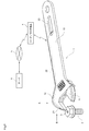
図1のモンキーレンチ1は、ボルト2をつかむ部分の幅、すなわち、上アゴ(固定ジョーと称される場合もある)12と下アゴ(可動ジョーと称される場合もある)11との間の幅を、ウォームギヤによって、ボルト2の頭部分の大きさに合わせて変更可能なレンチである。すなわち、モンキーレンチ1は、さまざまな種類のボルト2や図示を省略するナットの取付けに利用可能な工具である。モンキーレンチ1は、その全体、または、少なくともその一部が金属製であり、ここでは、少なくとも上アゴ12および把持部13が金属製であるものとする。モンキーレンチ1は、工具に対応する。 The monkey wrench 1 in FIG. 1 has the width of the portion that grips the bolt 2, that is, between the upper jaw (sometimes referred to as a fixed jaw) 12 and the lower jaw (sometimes referred to as a movable jaw) 11. It is a wrench whose width can be changed by a worm gear according to the size of the head portion of the bolt 2. That is, the monkey wrench 1 is a tool that can be used for attaching various types of bolts 2 and nuts (not shown). It is assumed that the monkey wrench 1 is made of metal in whole or at least a part thereof, and here, at least the upper jaw 12 and the grip portion 13 are made of metal. The monkey wrench 1 corresponds to a tool.

ボルト2には、ICタグ3が取り付けられている。ICタグ3には、ボルト2の種類やボルト2を取り付ける装置または部品や取付け個所などの固有の情報が記録されている。ICタグ3についての詳細は、図2および図3を用いて後述する。 An IC tag 3 is attached to the bolt 2. The IC tag 3 records unique information such as the type of the bolt 2 and the device or component for attaching the bolt 2 and the attachment location. Details of the IC tag 3 will be described later with reference to FIGS. 2 and 3.

モンキーレンチ1は、ボルト2等の取付け作業を妨げない上アゴ12の先端部分(例えば、作業時にボルトに当たらない部分)に、ICタグ検出部21を有する。ICタグ検出部21は、ボルト2に取り付けられたICタグ3を検出し、ICチップ32に記憶されている情報を読み取る。モンキーレンチ1の上アゴ12の先端部分にICタグ検出部21が設けられていることにより、ICタグ検出部21をICタグ3に近接させて検出させる動作と、モンキーレンチ1によりボルト2を取り付ける、または、取り外す動作との移行距離が短くスムーズになり好適である。 The monkey wrench 1 has an IC tag detection unit 21 at a tip portion (for example, a portion that does not hit the bolt during work) of the upper jaw 12 that does not interfere with the attachment work of the bolt 2 and the like. The IC tag detection unit 21 detects the IC tag 3 attached to the bolt 2 and reads the information stored in the IC chip 32. Since the IC tag detection unit 21 is provided at the tip of the upper jaw 12 of the monkey wrench 1, the operation of causing the IC tag detection unit 21 to be detected close to the IC tag 3 and the bolt 2 being attached by the monkey wrench 1. Or, the transition distance from the removal operation is short and smooth, which is preferable.

ICタグ3とICタグ検出部21とのICタグ通信には、例えば、周波数920MHzの電波を用いることが可能である。図1においては、ICタグ検出部21の第1の例であるICタグ検出部21aが図示されている。ICタグ検出部21の詳細については、図4〜図18を用いて後述する。 For the IC tag communication between the IC tag 3 and the IC tag detection unit 21, for example, a radio wave having a frequency of 920 MHz can be used. In FIG. 1, an IC tag detection unit 21a, which is a first example of the IC tag detection unit 21, is shown. Details of the IC tag detection unit 21 will be described later with reference to FIGS. 4 to 18.

ICタグ検出部21に読み取られた情報は、タグ情報伝送部22を介して、リーダ/ライタ通信部23に供給される。(図1においては、リーダ/ライタ通信部23の第1の例である、後述するリーダ/ライタ通信部23aが図示されている。)換言すれば、リーダ/ライタ端末4がICタグ3とモンキーレンチ1を介して情報を授受する場合、タグ情報伝送部22には、高周波(例えば920MHz)の電流や電圧が供給される(この詳細については、図26にてスロットアンテナの説明として後述する)。タグ情報伝送部22には、電気伝導性を有する芯線(詳細は後述する)が含まれ、高周波の電流は芯線を流れる。タグ情報伝送部22の詳細については、図19〜図23を用いて後述する。なお、リーダ/ライタ端末4は不図示の作業者が作業する腕などの近隣に所持するのが望ましい。 The information read by the IC tag detection unit 21 is supplied to the reader / writer communication unit 23 via the tag information transmission unit 22. (In FIG. 1, a reader / writer communication unit 23a, which is a first example of the reader / writer communication unit 23, is shown.) In other words, the reader / writer terminal 4 has an IC tag 3 and a monkey. When information is exchanged via the wrench 1, a high-frequency (for example, 920 MHz) current or voltage is supplied to the tag information transmission unit 22 (details of this will be described later as a description of the slot antenna in FIG. 26). .. The tag information transmission unit 22 includes a core wire having electrical conductivity (details will be described later), and a high-frequency current flows through the core wire. Details of the tag information transmission unit 22 will be described later with reference to FIGS. 19 to 23. It is desirable that the reader / writer terminal 4 be carried in the vicinity of an arm or the like on which an unillustrated worker works.

リーダ/ライタ通信部23は、リーダ/ライタ端末4と情報を授受するものである。リーダ/ライタ通信部23は、タグ情報伝送部22を介して供給された情報を、リーダ/ライタ端末4に送信する。リーダ/ライタ通信部23の詳細については、図24〜図34を用いて後述する。 The reader / writer communication unit 23 exchanges information with the reader / writer terminal 4. The reader / writer communication unit 23 transmits the information supplied via the tag information transmission unit 22 to the reader / writer terminal 4. Details of the reader / writer communication unit 23 will be described later with reference to FIGS. 24 to 34.

リーダ/ライタ端末4は、受信した情報を、ネットワーク5を介して、サーバ6に送信する。あるいは、リーダ/ライタ端末4がネットワーク5やサーバ6の役割を内蔵していてもよい。ここではそれぞれの役割が分離されている場合を代表として示している。サーバ6には、ボルト2に関する情報が記録され、工程に必要な管理に関する処理が実行される。これにより、モンキーレンチ1により所定の箇所に取り付けられたボルト2の固有情報が、サーバ6により管理可能となる。 The reader / writer terminal 4 transmits the received information to the server 6 via the network 5. Alternatively, the reader / writer terminal 4 may have a built-in role of the network 5 or the server 6. Here, the case where each role is separated is shown as a representative. Information about the bolt 2 is recorded in the server 6, and processing related to management necessary for the process is executed. As a result, the unique information of the bolt 2 attached to the predetermined position by the monkey wrench 1 can be managed by the server 6.

例えば、サーバ6に、ボルト2の在庫数が記録されていた場合、サーバ6は、受信された情報に基づいて、在庫数を把握することが可能であり、必要に応じて、ボルト2の発注処理を行うことが可能である。 For example, when the stock quantity of the bolt 2 is recorded in the server 6, the server 6 can grasp the stock quantity based on the received information, and orders the bolt 2 as needed. It is possible to perform processing.

また、例えば、サーバ6には、ボルト2と、そのボルト2を取り付けるべき部品等の情報を記録するようにしてもよい。例えば、ボルト2を取り付けるべき部品(図示せず)等の所定の場所に、その部品の固有情報が記録されたICタグ3を取り付けておき、部品に取り付けられたICタグ3と、ボルト2に取り付けられたICタグ3とを連続してICタグ検出部21を用いて読み取り、タグ情報伝送部22およびリーダ/ライタ通信部23を介して、リーダ/ライタ端末4に送信し、サーバ6により管理することができるようにしてもよい。これにより、いずれの部品のいずれの箇所に特定のボルト2が取り付けられたかを、サーバ6により管理することが可能となる。 Further, for example, the server 6 may record information such as the bolt 2 and the parts to which the bolt 2 is to be attached. For example, an IC tag 3 in which unique information of the part is recorded is attached to a predetermined place such as a part (not shown) to which the bolt 2 is to be attached, and the IC tag 3 and the bolt 2 attached to the part are attached. The attached IC tag 3 is continuously read by the IC tag detection unit 21, transmitted to the reader / writer terminal 4 via the tag information transmission unit 22 and the reader / writer communication unit 23, and managed by the server 6. You may be able to do it. As a result, the server 6 can manage which part of which part the specific bolt 2 is attached to.

また、サーバ6は、誤ったボルト2が取り付けられた場合、エラーメッセージを送信し、ネットワーク5を介して、例えば、作業者が所持しているリーダ/ライタ端末4に送信するものとしてもよい。リーダ/ライタ端末4は、受信したエラーメッセージを出力し、作業者に、部品が誤っていることを通知することが可能である。これにより、部品の取り付けの不具合を防止することが可能となる。 Further, when the wrong bolt 2 is attached, the server 6 may transmit an error message and transmit it to, for example, a reader / writer terminal 4 owned by the operator via the network 5. The reader / writer terminal 4 can output the received error message and notify the operator that the component is incorrect. This makes it possible to prevent defects in the attachment of parts.

また、必要に応じて、ICタグ3に記録したい情報を、サーバ6から送信し、ネットワーク5を介して、リーダ/ライタ端末4に送信するようにしてもよい。リーダ/ライタ通信部23は、リーダ/ライタ端末4から供給された情報を、タグ情報伝送部22を介して、ICタグ検出部21に供給する。ICタグ検出部21は、供給された情報を、ICタグ3に記録させることができる。 Further, if necessary, the information to be recorded in the IC tag 3 may be transmitted from the server 6 and transmitted to the reader / writer terminal 4 via the network 5. The reader / writer communication unit 23 supplies the information supplied from the reader / writer terminal 4 to the IC tag detection unit 21 via the tag information transmission unit 22. The IC tag detection unit 21 can record the supplied information in the IC tag 3.

次に、図2および図3を参照して、ICタグ3の例について説明する。 Next, an example of the IC tag 3 will be described with reference to FIGS. 2 and 3.

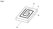
ICタグ3には、例えば、図2に示される小型のコイルアンテナ型のICタグ3aを用いることが可能である。ICタグ3aとしては、例えば、日立化成IM5−PK2525などの小型タグ(サイズ2.5mm×2.5mm×0.4mm)などを用いると好適である。ICタグ3aには、基板31上に、保守管理に必要な固有情報が記録されたICチップ32、および、外部と通信を行うためのコイルアンテナ33が搭載されている。 For the IC tag 3, for example, a small coil antenna type IC tag 3a shown in FIG. 2 can be used. As the IC tag 3a, for example, it is preferable to use a small tag (size 2.5 mm × 2.5 mm × 0.4 mm) such as Hitachi Kasei IM5-PK2525. The IC tag 3a has an IC chip 32 on which unique information necessary for maintenance management is recorded and a coil antenna 33 for communicating with the outside on a substrate 31.

また、ICタグ3には、例えば、図3に示されるように、小型の放射アンテナ型のICタグ3bを用いることが可能である。ICタグ3bには、シール基板34上に、保守管理に必要な固有情報が記録されたICチップ32、および、外部と通信を行うための放射型のアンテナ35が搭載されている。アンテナ35は、コイルアンテナ部分と放射アンテナ部分とで構成されている事例を示している。 Further, as the IC tag 3, for example, as shown in FIG. 3, a small radiation antenna type IC tag 3b can be used. The IC tag 3b has an IC chip 32 on which unique information necessary for maintenance management is recorded on a seal substrate 34, and a radial antenna 35 for communicating with the outside. The antenna 35 shows an example composed of a coil antenna portion and a radiation antenna portion.

次に、図4〜図10を参照して、ICタグ検出部21の第1の例であるICタグ検出部21aについて説明する。 Next, the IC tag detection unit 21a, which is the first example of the IC tag detection unit 21, will be described with reference to FIGS. 4 to 10.

図4は、図1における矢印Bの方向から見たICタグ検出部21aの拡大斜視図である。ICタグ検出部21aは、上アゴ12の端部を、側面を含んで上面と下面(ICタグ3の検出面)を貫通するように切り欠くことによって生成される空間に形成される。この切り欠きは、モンキーレンチ1の強度を損なうことのない、十分小さなものであり、例えば、切り欠きの幅を1.3mm程度、切り欠きの奥行きを4.0mm程度とすることができる。なお、ICタグ検出部21aは、図1に示す構成では、ボルト2が当たって損傷を受けないように、上アゴ12のうち、下アゴ11と対向する開口部側には位置しておらず、それとは反対の上アゴ12の外周側に位置している事例を示している。 FIG. 4 is an enlarged perspective view of the IC tag detection unit 21a seen from the direction of the arrow B in FIG. The IC tag detection unit 21a is formed in a space created by cutting out the end portion of the upper jaw 12 so as to penetrate the upper surface and the lower surface (detection surface of the IC tag 3) including the side surface. This notch is sufficiently small without impairing the strength of the monkey wrench 1. For example, the width of the notch can be about 1.3 mm and the depth of the notch can be about 4.0 mm. In the configuration shown in FIG. 1, the IC tag detection unit 21a is not located on the opening side of the upper jaw 12 facing the lower jaw 11 so as not to be damaged by the bolt 2. , On the contrary, the case where it is located on the outer peripheral side of the upper jaw 12 is shown.

これ以降、切り欠きにより生成される空間を内部空間S1、その外部の空間を外部空間と称する。内部空間S1には、タグ情報伝送部22の芯線41が突出し、接続点42によって、切り欠き内部の金属部分、すなわち、アースとして機能している部分に、例えば、ハンダ付けなどにより電気的に接続されている。内部空間S1に露出している芯線41は、図4のように直線状でなくてもよく、内部空間S1内で曲線状に湾曲していてもよいが、芯線41同士が延伸して内部空間S1内を1周以上してからアースに接続するような、芯線41を延ばして巻くループアンテナとする場合に生じる芯線41同士が交差してしまう部分を有さないことが望ましい。これは、ICタグ検出部21a内の内部構造が複雑であるほど工具に加わる衝撃に対して不利になるためである。換言すれば、芯線41は、直線状、または、平面視したとき(平面に投影したとき)に周方向における角度が同じ角度となるような重なり部分を有さない。すなわち、芯線41は、直線状、またはそれに近い形であり、ループアンテナの形状を有していない。 Hereinafter, the space created by the notch is referred to as an internal space S1, and the space outside the space is referred to as an external space. The core wire 41 of the tag information transmission unit 22 projects into the internal space S1, and is electrically connected to the metal portion inside the notch, that is, the portion functioning as a ground by soldering, for example, by the connection point 42. Has been done. The core wire 41 exposed in the internal space S1 does not have to be linear as shown in FIG. 4, and may be curved in a curved shape in the internal space S1, but the core wires 41 are extended to each other to form an internal space. It is desirable that there is no portion where the core wires 41 intersect with each other, which occurs when the loop antenna is formed by extending and winding the core wires 41, such as connecting to the ground after making one or more turns in S1. This is because the more complicated the internal structure inside the IC tag detection unit 21a, the more disadvantageous it is against the impact applied to the tool. In other words, the core wire 41 does not have a linear or overlapping portion such that the angles in the circumferential direction are the same when viewed in a plane (projected on a plane). That is, the core wire 41 has a linear shape or a shape close to it, and does not have the shape of a loop antenna.

内部空間S1は、例えば、樹脂等の、電気伝導性を有さず、磁界を透過する充填材43により充填される。充填材43がその周辺の金属部分とは異なる色である場合、右利きの作業者が図1のモンキーレンチを用いて作業を行う状態で、作業者が、ICタグ検出部21aの位置を確認しやすいため、ICタグ3にICタグ検出部21aを容易に近接させることができる。 The internal space S1 is filled with a filler 43 that does not have electrical conductivity and transmits a magnetic field, such as a resin. When the filler 43 has a color different from that of the metal parts around it, the worker confirms the position of the IC tag detection unit 21a while the right-handed worker is working with the monkey wrench shown in FIG. Therefore, the IC tag detection unit 21a can be easily brought close to the IC tag 3.

なお、不透明な充填材43を内部空間S1に充填した場合、芯線41および接続点42は外部空間から見えなくなるが、その位置などを説明するため、各図面においては、充填材43を透過して芯線41および接続点42を図示し、説明するものとする。 When the opaque filler 43 is filled in the internal space S1, the core wire 41 and the connection point 42 are invisible from the external space, but in order to explain the positions and the like, the filler 43 is transmitted through the filler 43 in each drawing. The core wire 41 and the connection point 42 will be illustrated and described.

リーダ/ライタ端末4がモンキーレンチ1を介してICタグ3と通信する場合、タグ情報伝送部22には、高周波の電流や電圧が供給される。すなわち、ICタグ検出部21aの芯線41には、高周波の電流や電圧が供給される(この詳細については、図5〜8等を用いて後述する)。上アゴ12の金属部分はアースとして機能するため、電気伝導性を有する芯線41は、接続点42の地点でショートされた状態となり、芯線41には、短絡状態にみられる大きな電流が発生する。したがって、芯線41を流れる高周波電流により発生する磁界φは大きくなり、金属部分で囲まれた内部空間S1内の充填材43が充填された部分を透過して、外部空間にまで広がることが可能となる。 When the reader / writer terminal 4 communicates with the IC tag 3 via the monkey wrench 1, a high-frequency current or voltage is supplied to the tag information transmission unit 22. That is, a high-frequency current or voltage is supplied to the core wire 41 of the IC tag detection unit 21a (details of this will be described later with reference to FIGS. 5 to 8 and the like). Since the metal portion of the upper jaw 12 functions as a ground, the core wire 41 having electrical conductivity is in a short-circuited state at the connection point 42, and a large current seen in the short-circuited state is generated in the core wire 41. Therefore, the magnetic field φ generated by the high-frequency current flowing through the core wire 41 becomes large, and it is possible to pass through the portion filled with the filler 43 in the internal space S1 surrounded by the metal portion and spread to the external space. Become.

次に、図5〜図10を用いて、ICタグ検出部21aとICタグ3aとの情報の授受について説明する。 Next, the exchange of information between the IC tag detection unit 21a and the IC tag 3a will be described with reference to FIGS. 5 to 10.

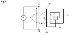
図5に、芯線41とICタグ3aのコイルアンテナ33との電磁誘導結合を示す等価回路を示す。 FIG. 5 shows an equivalent circuit showing an electromagnetic induction coupling between the core wire 41 and the coil antenna 33 of the IC tag 3a.

芯線41がICタグ検出部21aの内部空間S1に突出する点(内部空間S1において接続点42とは反対側の点)と接続点42を、それぞれP1およびQ1とすると、高周波電流が供給されたICタグ検出部21aの芯線41には大きな短絡電流iが流れる。この電流iにより発生する磁界φの一部、つまり、磁界φ1が、コイルアンテナ33を貫通する(図中磁界φ2で示される漏れ磁界も存在する)ことにより、コイルアンテナ33に電流iが流れ、ICチップ32が動作するために必要な電圧が発生する。この電磁誘導により、ICチップ32が動作する。 Assuming that the point where the core wire 41 protrudes into the internal space S1 of the IC tag detection unit 21a (the point opposite to the connection point 42 in the internal space S1) and the connection point 42 are P1 and Q1, respectively, a high frequency current is supplied. flowing a large short circuit current i 1 is the core wire 41 of the IC tag detecting section 21a. A part of the magnetic field φ generated by the current i 1 , that is, the magnetic field φ 1 penetrates the coil antenna 33 (there is also a leakage magnetic field indicated by the magnetic field φ 2 in the figure), so that the current i 2 is generated in the coil antenna 33. The current flows and the voltage required for the IC chip 32 to operate is generated. The IC chip 32 operates by this electromagnetic induction.

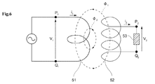
図6〜図8を参照し、この電磁誘導結合をトランス結合として説明する。 This electromagnetic induction coupling will be described as a transformer coupling with reference to FIGS. 6 to 8.

図6に、トランスモデルの等価回路を示す。トランスの1次側の両端P1およびQ1間の電圧をV、巻き数をNとし、トランスの2次側の負荷53の両端P2およびQ2間に発生する電圧をV、巻き数をNとしたとき、結合係数をkとして、次の数式(1)が成り立つ。結合係数kは、主に芯線41とコイルアンテナ33との距離によって決まる0〜1の値である。 FIG. 6 shows an equivalent circuit of the transformer model. The voltage between both ends P1 and Q1 on the primary side of the transformer is V 1 , the number of turns is N 1 , the voltage generated between both ends P2 and Q2 of the load 53 on the secondary side of the transformer is V 2 , and the number of turns is N. When it is 2 , the following formula (1) holds, where k is the coupling coefficient. The coupling coefficient k is a value of 0 to 1 mainly determined by the distance between the core wire 41 and the coil antenna 33.

数式(1)
/N=kV/V・・・(1)
Formula (1)
N 1 / N 2 = kV 1 / V 2 ... (1)

結合係数kは、主に芯線41とコイルアンテナ33との距離によって決まる0〜1の値である。すなわち、結合係数kは、一次側コイルに流れる電流iにより発生する磁界のうち、トランス結合の有効成分となる磁界φ1と、トランス結合に寄与しない漏れ成分φ2との割合で決まるものである。 The coupling coefficient k is a value of 0 to 1 mainly determined by the distance between the core wire 41 and the coil antenna 33. That is, the coupling coefficient k, of the magnetic field generated by the current i 1 flowing through the primary coil, the magnetic field φ1 as the active ingredient of the transformer coupling, but determined by the ratio of the leakage component φ2 which does not contribute to the transformer coupling.

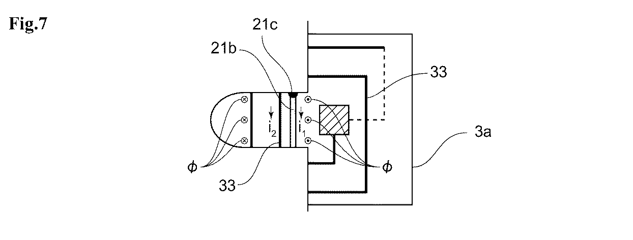
図7に、ICタグ検出部21aとICタグ3aとが接近した場合の電流の方向と発生する磁界φの概略図を示す。図7においては、丸の中に×の記号で、図の紙面の手前側から向こう側に向けて突き抜ける磁界φが、丸の中に黒点の記号で、図の紙面の向こう側から手前側に向けて突き抜ける磁界φが、それぞれ示されている。図6の一次側コイルは、図7のICタグ検出部21aの芯線41が対応し、図6の二次側コイルは、図7のICタグ3aのコイルアンテナ33が対応する。また、図6の負荷53は、図7のICチップ32が対応する。そして、一次側コイルに流れる電流iには、芯線41が接続点42によりショートすることにより流れる短絡電流に対応する。すなわち、ICタグ検出部21aとICタグ3aとが接近した場合に発生するICチップ32が動作するための電圧は、式(1)を用いて求めることができる。 FIG. 7 shows a schematic view of the direction of the current and the generated magnetic field φ when the IC tag detection unit 21a and the IC tag 3a are close to each other. In FIG. 7, the magnetic field φ that penetrates from the front side to the other side of the paper surface in the figure with the symbol × in the circle is the symbol of the black dot in the circle, from the other side to the front side of the paper surface in the figure. The magnetic field φ that penetrates toward each other is shown. The primary side coil of FIG. 6 corresponds to the core wire 41 of the IC tag detection unit 21a of FIG. 7, and the secondary side coil of FIG. 6 corresponds to the coil antenna 33 of the IC tag 3a of FIG. Further, the load 53 in FIG. 6 corresponds to the IC chip 32 in FIG. 7. The current i 1 flowing through the primary coil corresponds to the short-circuit current that flows when the core wire 41 is short-circuited by the connection point 42. That is, the voltage for operating the IC chip 32, which is generated when the IC tag detection unit 21a and the IC tag 3a are close to each other, can be obtained by using the equation (1).

図6の一次側コイルに対応する芯線41は、平面視したとき(平面に投影したとき)に芯線41同士が交差しない、すなわち、ループコイルを形成しないため、1回巻き以下で、かつ、短い伝導体である。そのため、図6の一次側のコイルに相当する巻き数N1を求める必要がある。そこで、コイルアンテナ33を正方形のコイルとした場合、トランス結合に加わる磁界φの発生区間が、正方形の四辺のどの区間を占めるか、その割合で置き換えて考えると、正方形の四辺のうちの一辺に対応している。すなわち、一次側コイルを1/4回巻きであるものとみなすことができる。 The core wires 41 corresponding to the primary coil in FIG. 6 do not intersect with each other when viewed in a plane (projected on a plane), that is, do not form a loop coil, so that the core wires 41 are wound once or less and are short. It is a conductor. Therefore, it is necessary to obtain the number of turns N1 corresponding to the coil on the primary side of FIG. Therefore, when the coil antenna 33 is a square coil, one of the four sides of the square is considered by substituting the ratio of which section of the four sides of the square the generation section of the magnetic field φ1 applied to the transformer coupling occupies. It corresponds to. That is, the primary coil can be regarded as being wound 1/4 times.

そして、ICタグ3aのコイルアンテナ33の巻き数を、例えば、2.5とし、トランス結合の有効成分となる磁界φと、トランス結合に寄与しない漏れ成分φとの割合が同じ、すなわち、結合係数kを0.5とした場合、ICチップ32が動作するための電圧Vは、次の数式(2)で求められる。 Then, the number of turns of the coil antenna 33 of the IC tag 3a is set to, for example, 2.5, and the ratio of the magnetic field φ 1 which is the active component of the transformer coupling and the leakage component φ 2 which does not contribute to the transformer coupling is the same, that is, When the coupling coefficient k is 0.5, the voltage V 2 for operating the IC chip 32 can be obtained by the following mathematical formula (2).

数式(2)
=0.5×V×2.5/0.25=5V・・・(2)
Formula (2)
V 2 = 0.5 x V 1 x 2.5 / 0.25 = 5 V 1 ... (2)

すなわち、図8に示されるように、芯線41が接続点42に接続されることによるショート電流iにより発生する磁界φの少なくとも一部がICタグ3aのコイルアンテナ33を貫通することにより、電磁誘導結合が発生し、コイルアンテナ33に電流が流れ、ICチップ32が動作するために必要な電圧が発生する。発生する電圧は、コイルアンテナ33の巻き数に比例する。このため、ICタグ検出部21aの芯線41が、平面視したとき(平面に投影したとき)に芯線41同士が交差していない、すなわち、コイルの形状のアンテナを有していないのにもかかわらず、ICチップ32が動作する。これにより、ICタグ検出部21aは、ある程度の大きさを必要とする1回巻き以上のコイルアンテナを含むことなく、ICタグ3を検出し、情報を授受することができる。これにより、モンキーレンチ1に、十分な強度が必要な場合や小型化が必要な場合においても、ICタグ検出部21aを微小なスペースに設けることが可能となる。 That is, as shown in FIG. 8, at least a part of the magnetic field generated by the short circuit current i 1 due to the core wire 41 is connected to the connection point 42 phi penetrates the coil antenna 33 of the IC tag 3a, electromagnetic Inductive coupling occurs, current flows through the coil antenna 33, and the voltage required for the IC chip 32 to operate is generated. The generated voltage is proportional to the number of turns of the coil antenna 33. Therefore, even though the core wires 41 of the IC tag detection unit 21a do not intersect with each other when viewed in a plane (projected on a plane), that is, they do not have an antenna in the shape of a coil. Instead, the IC chip 32 operates. As a result, the IC tag detection unit 21a can detect the IC tag 3 and exchange information without including a coil antenna having one or more turns, which requires a certain size. As a result, the IC tag detection unit 21a can be provided in a minute space even when the monkey wrench 1 needs to have sufficient strength or miniaturization.

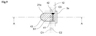
次に、図9に、図1を用いて説明したモンキーレンチ1のICタグ検出部21aを、作業者がICタグ3aに近接させた場合の拡大図を示す。図9に示される一点鎖線C1は、ICタグ検出部21aの切り欠き部分の長手方向における中心線(換言すれば、内部空間S1の長手方向の中心線)であり、一点鎖線C2は、ICタグ3aの中心線である。ICタグ検出部21aの充填材43が不透明であった場合、芯線41と接続点42は作業者から確認することはできず、また、充填材43に透明な材質を用いたとしても、作業者から確認が容易な内部空間S1を形成する切り欠き部分の体積に対して、芯線41と接続点42は非常に小さい。このため、図9に示すように、ICタグ検出部21aをICタグ3aに接近させる場合、作業者には、ICタグ3aの中心線C2に対して、ICタグ検出部21aの切り欠き部分の長手方向の中心線C1を合わせようとすると考えられる。 Next, FIG. 9 shows an enlarged view when the operator brings the IC tag detection unit 21a of the monkey wrench 1 described with reference to FIG. 1 close to the IC tag 3a. The alternate long and short dash line C1 shown in FIG. 9 is the center line in the longitudinal direction of the cutout portion of the IC tag detection unit 21a (in other words, the center line in the longitudinal direction of the internal space S1), and the alternate long and short dash line C2 is the IC tag. It is the center line of 3a. When the filler 43 of the IC tag detection unit 21a is opaque, the core wire 41 and the connection point 42 cannot be confirmed by the operator, and even if a transparent material is used for the filler 43, the operator cannot confirm it. The core wire 41 and the connection point 42 are very small with respect to the volume of the notched portion forming the internal space S1 which can be easily confirmed from the above. Therefore, as shown in FIG. 9, when the IC tag detection unit 21a is brought close to the IC tag 3a, the operator is asked to the notched portion of the IC tag detection unit 21a with respect to the center line C2 of the IC tag 3a. It is considered that the center line C1 in the longitudinal direction is to be aligned.

ここで、芯線41の位置が、ICタグ3aのICチップ32の真上に位置した場合、芯線41に流れる電流により発生する磁界φによりコイルアンテナ33に発生する電流が、ICチップ32を挟んだ両側において打ち消し合ってしまうため、ICタグ検出部21aはICタグ3aを検出することができない。これを防ぐため、芯線41の少なくとも一部は、ICタグ検出部21aの切り欠き部分の中心からオフセットされた位置(たとえば、図9に示されるように、切り欠き部分の長手方向の中心線C1から所定の距離だけオフセットされた位置C3)に配置されるようにすると好適である。なお、ICタグ検出部21aは、切り欠き部分の長手方向の中心からオフセットされた位置としても良いが、短手方向の中心からオフセットされた位置とすることもできる。また、内部空間S1のうち、芯線41が露出している部分が磁界の発生場所となり、芯線41から接続点42までの内部空間S1の距離が短くなると、磁界の発生が少なくなってしまう。しかしながら、芯線41から接続点42までの内部空間S1の距離が長いと、内部空間S1から外部空間に出て行く磁界が多くなり検出感度は高くなる一方、機械的強度が低下する。このため、芯線41が内部空間S1に突出する位置(内部空間S1において接続点42とは反対側の点)、および、接続点42の位置は、工具の所定強度を保ちつつ一定の検出感度を確保することができる所定の距離(長さ)を保つ(内部空間S1内で芯線41が所定以上の長さを有する)とともに、ICタグ3aの検出面に近くなるようにすると好適である。 Here, when the position of the core wire 41 is located directly above the IC chip 32 of the IC tag 3a, the current generated in the coil antenna 33 due to the magnetic field φ generated by the current flowing in the core wire 41 sandwiches the IC chip 32. The IC tag detection unit 21a cannot detect the IC tag 3a because they cancel each other out on both sides. In order to prevent this, at least a part of the core wire 41 is offset from the center of the notched portion of the IC tag detection unit 21a (for example, as shown in FIG. 9, the center line C1 in the longitudinal direction of the notched portion). It is preferable that the position C3) is offset from the position C3) by a predetermined distance. The IC tag detection unit 21a may be at a position offset from the center in the longitudinal direction of the cutout portion, but may also be at a position offset from the center in the lateral direction. Further, in the internal space S1, the portion where the core wire 41 is exposed becomes the place where the magnetic field is generated, and when the distance of the internal space S1 from the core wire 41 to the connection point 42 is shortened, the generation of the magnetic field is reduced. However, if the distance of the internal space S1 from the core wire 41 to the connection point 42 is long, the magnetic field that goes out from the internal space S1 to the external space increases, the detection sensitivity increases, and the mechanical strength decreases. Therefore, the position where the core wire 41 protrudes into the internal space S1 (the point opposite to the connection point 42 in the internal space S1) and the position of the connection point 42 provide a constant detection sensitivity while maintaining a predetermined strength of the tool. It is preferable to maintain a predetermined distance (length) that can be secured (the core wire 41 has a length equal to or longer than a predetermined length in the internal space S1) and to be close to the detection surface of the IC tag 3a.

図10は、図9のA−A断面図である。芯線41の少なくとも一部をICタグ検出部21aの切り欠き部分の中心からオフセットされた位置に配置することにより、芯線41を流れるショート電流iにより発生する磁界φは、正方形のコイルアンテナ33の四辺のうちの一辺を貫通するので、コイルアンテナ33に発生する電流iは打ち消し合うことなく、ICタグ3aが起動する。したがって、ICタグ検出部21aはICタグ3aを検出することが可能となる。 FIG. 10 is a cross-sectional view taken along the line AA of FIG. By placing at least a portion of which is offset from the center of the notch portion of the IC tag detecting section 21a positions of the core wire 41, the magnetic field φ generated by the short circuit current i 1 flowing through the core 41, the square of the coil antenna 33 Since it penetrates one of the four sides, the current i 2 generated in the coil antenna 33 does not cancel each other out, and the IC tag 3a is activated. Therefore, the IC tag detection unit 21a can detect the IC tag 3a.

次に、図11〜図14を参照して、ICタグ検出部21の他の構成例のうち、上述したICタグ検出部21aと同様に、上アゴ12の角部分を含む切り欠きにより形成された内部空間S1を有するICタグ検出部21bおよびICタグ検出部21cについて説明する。 Next, with reference to FIGS. 11 to 14, among the other configuration examples of the IC tag detection unit 21, the IC tag detection unit 21a is formed by a notch including a corner portion of the upper jaw 12, similarly to the IC tag detection unit 21a described above. The IC tag detection unit 21b and the IC tag detection unit 21c having the internal space S1 will be described.

図11は、他の構成例に係り、モンキーレンチ1を図1に示す状態とは反対の裏返しにし、かつ図1における矢印Bの方向から見たときのICタグ検出部21bの拡大斜視図である。 FIG. 11 is an enlarged perspective view of the IC tag detection unit 21b when the monkey wrench 1 is turned upside down in the opposite direction to the state shown in FIG. 1 and viewed from the direction of arrow B in FIG. 1, according to another configuration example. is there.

ICタグ検出部21bは、上アゴ12の端部の裏面(ICタグ3と近接対向する面;図1では上アゴ12の下面)を、上アゴ12のうち裏面と側面の間の角部分を含みつつ、表面には貫通させない形状で切り欠いて形成される内部空間S1に形成される。この切り欠きは、モンキーレンチ1の強度を損なうことのない、十分小さなものであり、例えば、ICタグ3aの一例として、UHF帯(860〜960MHz)で通信する、日立化成IM5−PK2525型を検出する場合、切り欠きの幅および高さ(検出面からの深さ)を2.5mm程度、切り欠きの奥行き(裏面に沿った長手方向の寸法)を5.0mm程度とすることができる。上述したICタグ検出部21aと同様に、ICタグ検出部21bの内部空間S1には、タグ情報伝送部22の芯線41が突出し、接続点42によって、切り欠き内部の金属部分に、例えば、ハンダ付けなどにより電気的に接続されている。内部空間S1は、例えば、樹脂等の、電気伝導性を有さず、磁界を透過する充填材43により充填される。 The IC tag detection unit 21b uses the back surface of the end portion of the upper jaw 12 (the surface adjacent to the IC tag 3; the lower surface of the upper jaw 12 in FIG. 1) and the corner portion between the back surface and the side surface of the upper jaw 12. It is formed in the internal space S1 which is cut out in a shape that does not penetrate the surface while being included. This notch is sufficiently small that does not impair the strength of the monkey wrench 1. For example, as an example of the IC tag 3a, Hitachi Kasei IM5-PK2525 type that communicates in the UHF band (860 to 960 MHz) is detected. In this case, the width and height of the notch (depth from the detection surface) can be about 2.5 mm, and the depth of the notch (dimension in the longitudinal direction along the back surface) can be about 5.0 mm. Similar to the IC tag detection unit 21a described above, the core wire 41 of the tag information transmission unit 22 protrudes into the internal space S1 of the IC tag detection unit 21b, and the connection point 42 allows the metal portion inside the notch to be soldered, for example. It is electrically connected by soldering. The internal space S1 is filled with a filler 43 that does not have electrical conductivity and transmits a magnetic field, such as a resin.

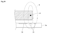
図12に、ICタグ検出部21bを備えたモンキーレンチ1の作業者が、ICタグ検出部21bをICタグ3aに近接させた場合のICタグ検出部21bおよびICタグ3aの拡大図を示す。上述したICタグ検出部21aと同様に、ICタグ検出部21bに位置する芯線41には、短絡状態にみられる大きな電流iが発生する。したがって、芯線41を流れる高周波電流iにより発生する磁界φは、図12に示されるように、金属部分で囲まれた内部空間S1内の充填材43が充填された部分を透過して、外部空間に広がり、そのうちの少なくとも一部がコイルアンテナ33を貫通することにより、コイルアンテナ33に電流iが流れる。これにより、ICチップ32が動作するために必要な誘導電圧が発生し、ICチップ32が動作する。したがって、ICタグ検出部21bは、ICタグ3を検出し、情報を授受することができる。また、内部空間S1のうち、芯線41が露出している部分が磁界の発生場所となり、芯線41から接続点42までの内部空間S1の距離が短くなると、磁界の発生が少なくなってしまう。しかしながら、芯線41から接続点42までの内部空間S1の距離が長いと、内部空間S1から外部空間に出て行く磁界が多くなり検出感度は高くなる一方、機械的強度が低下する。このため、芯線41が内部空間S1に突出する位置(内部空間S1において接続点42とは反対側の点)、および、接続点42の位置は、工具の所定強度を保ちつつ一定の検出感度を確保することができる所定の距離(長さ)を保つ(内部空間S1内で芯線41が所定以上の長さを有する)と共に、ICタグ3aの検出面に近くなるようにすると好適である。 FIG. 12 shows an enlarged view of the IC tag detection unit 21b and the IC tag 3a when the operator of the monkey wrench 1 provided with the IC tag detection unit 21b brings the IC tag detection unit 21b close to the IC tag 3a. Like the IC tag detecting section 21a as described above, the core wire 41 located in the IC tag detecting section 21b, a large current i 1 seen in a short-circuit condition occurs. Thus, the magnetic field φ generated by the high frequency current i 1 flowing through the core wire 41, as shown in FIG. 12, passes through the portion filled with the filler 43 in the internal space S1 surrounded by the metal part, the outside The current i 2 flows through the coil antenna 33 by spreading in the space and penetrating at least a part of the coil antenna 33. As a result, the induced voltage required for the IC chip 32 to operate is generated, and the IC chip 32 operates. Therefore, the IC tag detection unit 21b can detect the IC tag 3 and exchange information. Further, in the internal space S1, the portion where the core wire 41 is exposed becomes the place where the magnetic field is generated, and when the distance of the internal space S1 from the core wire 41 to the connection point 42 is shortened, the generation of the magnetic field is reduced. However, if the distance of the internal space S1 from the core wire 41 to the connection point 42 is long, the magnetic field that goes out from the internal space S1 to the external space increases, the detection sensitivity increases, and the mechanical strength decreases. Therefore, the position where the core wire 41 protrudes into the internal space S1 (the point opposite to the connection point 42 in the internal space S1) and the position of the connection point 42 provide a constant detection sensitivity while maintaining a predetermined strength of the tool. It is preferable to maintain a predetermined distance (length) that can be secured (the core wire 41 has a length equal to or longer than a predetermined length in the internal space S1) and to be close to the detection surface of the IC tag 3a.

また、ICタグ検出部21bを備えたモンキーレンチ1を右利きの作業者が使用している状態においては、作業者がICタグ検出部21bを目視することはできないため、作業者がICタグ検出部21bの位置を把握し、ICタグ3に正しく近接させることが困難となる。そこで、作業者が使用している状態で、ICタグ検出部21bの位置を把握することができるような目印をつけると好適である。図13は、ICタグ検出部21bを備えたモンキーレンチ1を右利きの作業者が使用している状態の、上アゴ12先端部分の拡大図である。図13に示されるように、目印61を、ICタグ検出部21bの芯線41の位置から少し離れた内部空間S1上に対応する位置に付ける。作業者が、目印61をICタグ3aの中央部分に合わせることにより、図10を用いて説明したように、芯線41を流れるショート電流iにより発生する磁界φは、正方形のコイルアンテナ33の四辺のうちの一辺を貫通する。したがって、コイルアンテナ33に発生する電流iが打ち消し合うことを防ぐことができ、ICタグ3の検出を確実に行うことが可能となる。 Further, when a right-handed worker is using the monkey wrench 1 provided with the IC tag detection unit 21b, the worker cannot visually check the IC tag detection unit 21b, so that the worker can detect the IC tag. It becomes difficult to grasp the position of the portion 21b and bring it close to the IC tag 3 correctly. Therefore, it is preferable to add a mark so that the position of the IC tag detection unit 21b can be grasped while the operator is using it. FIG. 13 is an enlarged view of the tip portion of the upper jaw 12 in a state where a right-handed worker is using the monkey wrench 1 provided with the IC tag detection unit 21b. As shown in FIG. 13, the mark 61 is attached to the position corresponding to the internal space S1 slightly away from the position of the core wire 41 of the IC tag detection unit 21b. Worker, by matching the marks 61 in the central portion of the IC tag 3a, as described with reference to FIG. 10, the magnetic field φ generated by the short circuit current i 1 flowing through the core 41, the four sides of the square of the coil antenna 33 Penetrate one side of. Therefore, it is possible to prevent the currents i 2 generated in the coil antenna 33 from canceling each other out, and it is possible to reliably detect the IC tag 3.

図14は、図1のモンキーレンチ1を裏返しにし、図1における矢印Bの方向から見たICタグ検出部21cの拡大斜視図である。 FIG. 14 is an enlarged perspective view of the IC tag detection unit 21c seen from the direction of the arrow B in FIG. 1 with the monkey wrench 1 of FIG. 1 turned inside out.

ICタグ検出部21cは、上アゴ12の端部の裏面(ICタグ3と近接対向する面;図1では上アゴ12の下面)を、上アゴ12のうち裏面と側面の間の角部分を含みつつ、表面には貫通させしない形状で、角部分の延伸方向に対して斜め方向に切り欠くことによって生成される内部空間S1に形成される。この切り欠きは、モンキーレンチ1の強度を損なうことのない、十分小さなものである。上述したICタグ検出部21aおよびICタグ検出部21bと同様に、ICタグ検出部21cの内部空間S1には、タグ情報伝送部22の芯線41が突出し、接続点42によって、切り欠き内部の金属部分に、例えば、ハンダ付けなどにより電気的に接続されている。内部空間S1は、例えば、樹脂等の、電気伝導性を有さず、磁界を透過する充填材43により充填される。ICタグ検出部21cの構造は、上アゴ12のうち裏面と側面の間の角部分の延伸方向に対して斜めに切り欠くことで、角部分の切り欠き残部が、芯線41を外部からの衝撃に対して保護する役割を果たすという特徴がある。 The IC tag detection unit 21c uses the back surface of the end portion of the upper jaw 12 (the surface facing the IC tag 3; the lower surface of the upper jaw 12 in FIG. 1) and the corner portion between the back surface and the side surface of the upper jaw 12. It is formed in the internal space S1 which is formed by cutting out the corner portion in an oblique direction with respect to the stretching direction so as to include the shape but not to penetrate the surface. This notch is small enough without compromising the strength of the monkey wrench 1. Similar to the IC tag detection unit 21a and the IC tag detection unit 21b described above, the core wire 41 of the tag information transmission unit 22 protrudes into the internal space S1 of the IC tag detection unit 21c, and the metal inside the notch is formed by the connection point 42. It is electrically connected to the portion by, for example, soldering. The internal space S1 is filled with a filler 43 that does not have electrical conductivity and transmits a magnetic field, such as a resin. The structure of the IC tag detection unit 21c is such that the corner portion between the back surface and the side surface of the upper jaw 12 is cut out diagonally with respect to the extending direction, so that the notched portion of the corner portion impacts the core wire 41 from the outside. It has the characteristic of playing a protective role against.

ICタグ検出部21cにおいても、上述したICタグ検出部21aおよびICタグ検出部21bと同様に、芯線41には、短絡状態にみられる大きな電流iが発生する。したがって、芯線41を流れる高周波電流iにより発生する磁界φは、金属部分で囲まれた内部空間S1内の充填材43が充填された部分を透過して、外部空間に広がり、そのうちの少なくとも一部がコイルアンテナ33を貫通する。それにより、コイルアンテナ33に電流iが流れる。これにより、ICチップ32が動作するために必要な誘導電圧が発生し、ICチップ32が動作する。したがって、ICタグ検出部21cは、ICタグ3を検出し、情報を授受することができる。また、内部空間S1のうち、芯線41が露出している部分が磁界の発生場所となり、芯線41から接続点42までの距離が短くなると、磁界の発生が少なくなってしまう。しかしながら、芯線41から接続点42までの内部空間S1の距離が長いと、内部空間S1から外部空間に出て行く磁界が多くなり検出感度は高くなる一方、機械的強度が低下する。このため、芯線41が内部空間S1に突出する位置(内部空間S1において接続点42とは反対側の点)、および、接続点42の位置は、工具の所定強度を保ちつつ一定の検出感度を確保することができる所定の距離(長さ)を保つ(内部空間S1内で芯線41が所定以上の長さを有する)とともに、ICタグ3aの検出面に近くなるようにすると好適である。 Also in the IC tag detecting section 21c, similarly to the IC tag detecting section 21a and the IC tag detecting section 21b described above, the core wire 41, a large current i 1 seen in a short-circuit condition occurs. Thus, the magnetic field φ generated by the high frequency current i 1 flowing through the core 41, filler 43 in the interior space S1, which is surrounded by the metal part passes through the portion filled, spreading to the external space, at least one of which The portion penetrates the coil antenna 33. As a result, the current i 2 flows through the coil antenna 33. As a result, the induced voltage required for the IC chip 32 to operate is generated, and the IC chip 32 operates. Therefore, the IC tag detection unit 21c can detect the IC tag 3 and exchange information. Further, in the internal space S1, the portion where the core wire 41 is exposed becomes the place where the magnetic field is generated, and when the distance from the core wire 41 to the connection point 42 is shortened, the generation of the magnetic field is reduced. However, if the distance of the internal space S1 from the core wire 41 to the connection point 42 is long, the magnetic field that goes out from the internal space S1 to the external space increases, the detection sensitivity increases, and the mechanical strength decreases. Therefore, the position where the core wire 41 protrudes into the internal space S1 (the point opposite to the connection point 42 in the internal space S1) and the position of the connection point 42 provide a constant detection sensitivity while maintaining a predetermined strength of the tool. It is preferable to maintain a predetermined distance (length) that can be secured (the core wire 41 has a length equal to or longer than a predetermined length in the internal space S1) and to be close to the detection surface of the IC tag 3a.

また、ICタグ検出部21cを備えたモンキーレンチ1を右利きの作業者が使用している状態においても、作業者がICタグ検出部21cの位置を把握することは困難である。そこで、作業者が使用している状態で、ICタグ検出部21cの位置を把握することができるような目印をつけると好適である。ICタグ検出部21cにおいても、ICタグ検出部21bと同様に、目印61を、平面視したときに、ICタグ検出部21cの芯線41の位置から少し離れた位置に付ける。それにより、図10を用いて説明したように、芯線41を流れるショート電流iにより発生する磁界φは、正方形のコイルアンテナ33の四辺のうちの一辺を貫通する。したがって、コイルアンテナ33に発生する電流iが打ち消し合うことを防ぐことができ、ICタグ3の検出を確実に行うことが可能となる。 Further, even when a right-handed worker is using the monkey wrench 1 provided with the IC tag detection unit 21c, it is difficult for the worker to grasp the position of the IC tag detection unit 21c. Therefore, it is preferable to add a mark so that the position of the IC tag detection unit 21c can be grasped while the operator is using it. Similarly to the IC tag detection unit 21b, the IC tag detection unit 21c also attaches the mark 61 to a position slightly distant from the position of the core wire 41 of the IC tag detection unit 21c when viewed in a plan view. Thereby, as explained with reference to FIG. 10, the magnetic field φ generated by the short circuit current i 1 flowing through the core wire 41, through the side of the four sides of the square of the coil antenna 33. Therefore, it is possible to prevent the currents i 2 generated in the coil antenna 33 from canceling each other, and it is possible to reliably detect the IC tag 3.

ICタグ検出部21a〜21cにおいては、その内部空間S1の大きさおよび形状によって、通信感度が異なるとともに、モンキーレンチ1の対応する部分の強度も異なるものとなる。ICタグ検出部21a〜21cにおいて、その通信感度が最もよいのは、ICタグ検出部21cであり、次いで、ICタグ検出部21aの通信感度がよく、ICタグ検出部21bの通信感度が最も低い。しかしながら、モンキーレンチ1の対応する部分の強度は、ICタグ検出部21bを用いた場合が最も強く、次いで、ICタグ検出部21aを用いた場合が強く、ICタグ検出部21cを用いた場合が最も弱い。すなわち、ICタグ検出部21a〜cの内のいずれをモンキーレンチ1に設けるかは、必要とされる通信感度と強度により定められるものとすることができる。 In the IC tag detection units 21a to 21c, the communication sensitivity differs depending on the size and shape of the internal space S1, and the strength of the corresponding portion of the monkey wrench 1 also differs. Among the IC tag detection units 21a to 21c, the IC tag detection unit 21c has the highest communication sensitivity, followed by the IC tag detection unit 21a having the highest communication sensitivity and the IC tag detection unit 21b having the lowest communication sensitivity. .. However, the strength of the corresponding portion of the monkey wrench 1 is strongest when the IC tag detection unit 21b is used, then is strong when the IC tag detection unit 21a is used, and when the IC tag detection unit 21c is used. The weakest. That is, which of the IC tag detection units 21a to 21c is provided on the monkey wrench 1 can be determined by the required communication sensitivity and strength.

次に、図15〜図17を参照して、ICタグ検出部21の他の構成例のうち、上アゴ12の角部分を含まない、いずれかの平面に対する切り欠きにより形成された内部空間S1を有するICタグ検出部21d、および、ICタグ検出部21eについて説明する。 Next, with reference to FIGS. 15 to 17, among the other configuration examples of the IC tag detection unit 21, the internal space S1 formed by a notch on any plane that does not include the corner portion of the upper jaw 12. The IC tag detection unit 21d and the IC tag detection unit 21e having the above will be described.

図15は、図1のモンキーレンチ1を裏返しにした(モンキーレンチ1を右利きの作業者が使用している状態において裏となる面を上面とした)場合のICタグ検出部21dの拡大斜視図である。 FIG. 15 shows an enlarged perspective view of the IC tag detection unit 21d when the monkey wrench 1 of FIG. 1 is turned inside out (the back surface is the upper surface when the monkey wrench 1 is used by a right-handed worker). It is a figure.

ICタグ検出部21dは、上アゴ12の一部がICタグ3の検出面を含んで貫通するよう(穴を形成するように)に円筒状に切り欠くことによって生成される内部空間S1に形成される。この切り欠きは、モンキーレンチ1の強度を損なうことのない、十分小さなものであり、例えば、切り欠きの円筒の径を5.0mm程度とすることができる。上述したICタグ検出部21a〜cと同様に、ICタグ検出部21dの内部空間S1には、タグ情報伝送部22の芯線41が突出し、接続点42によって、切り欠き内部の金属部分に、例えば、ハンダ付けなどにより電気的に接続されている。内部空間S1は、例えば、樹脂等の、電気伝導性を有さず、磁界を透過する充填材43により充填される。充填材43がその周辺の金属部分とは異なる色である場合、右利きの作業者が図1のモンキーレンチを用いて作業を行う状態で、作業者が、ICタグ検出部21dの位置を確認しやすいため、ICタグ3にICタグ検出部21dを容易に近接させることができる。 The IC tag detection unit 21d is formed in the internal space S1 created by cutting out a part of the upper jaw 12 in a cylindrical shape so as to include the detection surface of the IC tag 3 and penetrate (so as to form a hole). Will be done. This notch is sufficiently small without impairing the strength of the monkey wrench 1, and for example, the diameter of the notch cylinder can be about 5.0 mm. Similar to the IC tag detection units 21a to 21c described above, the core wire 41 of the tag information transmission unit 22 protrudes into the internal space S1 of the IC tag detection unit 21d, and the connection point 42 allows the metal portion inside the notch to be formed, for example. , It is electrically connected by soldering. The internal space S1 is filled with a filler 43 that does not have electrical conductivity and transmits a magnetic field, such as a resin. When the filler 43 has a color different from that of the metal parts around it, the worker confirms the position of the IC tag detection unit 21d while the right-handed worker is working with the monkey wrench shown in FIG. Therefore, the IC tag detection unit 21d can be easily brought close to the IC tag 3.

ICタグ検出部21dにおいても、ICタグ検出部21a〜21cと同様に、芯線41には、短絡状態にみられる大きな電流iが発生する。したがって、芯線41を流れる高周波電流iにより発生する磁界φは、金属部分で囲まれた内部空間S1内の充填材43が充填された部分を透過して、外部空間に広がり、そのうちの少なくとも一部がコイルアンテナ33を貫通する。それにより、コイルアンテナ33に電流iが流れ、ICチップ32が動作するために必要な誘導電圧が発生し、ICチップ32が動作する。したがって、ICタグ検出部21dは、ICタグ3を検出し、情報を授受することができる。 Also in the IC tag detecting section 21d, like the IC tag detecting section 21 a - 21 c, the core wire 41, a large current i 1 seen in a short-circuit condition occurs. Thus, the magnetic field φ generated by the high frequency current i 1 flowing through the core 41, filler 43 in the interior space S1, which is surrounded by the metal part passes through the portion filled, spreading to the external space, at least one of which The portion penetrates the coil antenna 33. As a result, the current i 2 flows through the coil antenna 33, the induced voltage required for the IC chip 32 to operate is generated, and the IC chip 32 operates. Therefore, the IC tag detection unit 21d can detect the IC tag 3 and exchange information.

また、ICタグ検出部21dの充填材43が不透明であった場合、芯線41と接続点42は作業者から確認することはできず、また、充填材43に透明な材質を用いたとしても、作業者から確認が容易な内部空間S1を形成する切り欠き部分の体積に対して、芯線41と接続点42は非常に小さい。このため、ICタグ検出部21dをICタグ3に接近させる場合、作業者には、ICタグ3の中心に対して、ICタグ検出部21dを平面視した場合の貫通孔部分の円中心を合わせようとすると考えられる。 Further, when the filler 43 of the IC tag detection unit 21d is opaque, the core wire 41 and the connection point 42 cannot be confirmed by the operator, and even if a transparent material is used for the filler 43, the core wire 41 and the connection point 42 cannot be confirmed. The core wire 41 and the connection point 42 are very small with respect to the volume of the notched portion forming the internal space S1 that can be easily confirmed by the operator. Therefore, when the IC tag detection unit 21d is brought close to the IC tag 3, the operator aligns the circular center of the through hole portion when the IC tag detection unit 21d is viewed in a plan view with respect to the center of the IC tag 3. It is thought that it will try.

ここで、芯線41の位置が、ICタグ3のICチップ32の真上に位置した場合、上述したように、磁界φによりコイルアンテナ33に発生する電流が、ICチップ32を挟んだ両側において打ち消し合ってしまうため、ICタグ検出部21dはICタグ3を検出することができない。これを防ぐため、芯線41の少なくとも一部は、上述した場合と同様に、ICタグ検出部21dの貫通孔を平面視した場合の円中心を通る中心線C1から所定の距離だけオフセットされた位置C3に配置されるようにすると好適である。 Here, when the position of the core wire 41 is located directly above the IC chip 32 of the IC tag 3, as described above, the current generated in the coil antenna 33 due to the magnetic field φ cancels out on both sides of the IC chip 32. The IC tag detection unit 21d cannot detect the IC tag 3 because it matches. In order to prevent this, at least a part of the core wire 41 is offset by a predetermined distance from the center line C1 passing through the center of the circle when the through hole of the IC tag detection unit 21d is viewed in a plane, as in the case described above. It is preferable to arrange it at C3.

また、内部空間S1を形成するための切り欠きは、円筒状でなくても構わなく、モンキーレンチ1の強度を損なうことのない大きさであれば、いずれの形状であってもよいことは言うまでもない。 Further, it goes without saying that the notch for forming the internal space S1 does not have to be cylindrical and may have any shape as long as it does not impair the strength of the monkey wrench 1. No.

次に、図16は、図1のモンキーレンチ1を裏返しにした(モンキーレンチ1を右利きの作業者が使用している状態において裏となる面を上面とした)場合の、ICタグ検出部21eの拡大斜視図である。 Next, FIG. 16 shows an IC tag detection unit when the monkey wrench 1 of FIG. 1 is turned inside out (the back surface is the upper surface when the monkey wrench 1 is used by a right-handed worker). It is an enlarged perspective view of 21e.

ICタグ検出部21eは、上アゴ12のいずれかの平面(図16においては、図1のモンキーレンチ1を裏返しにした場合に上側になる平面)を、貫通させることなく、くり貫くように(へこみを形成するように)切り欠くことによって生成される内部空間S1に形成される。この切り欠きは、モンキーレンチ1の強度を損なうことのない、十分小さなものであり、例えば、切り欠きの径を5.0mm程度、高さ(検出面からの深さ)を3.0mm程度とすることができる。上述したICタグ検出部21a〜21dと同様に、ICタグ検出部21eの内部空間S1には、タグ情報伝送部22の芯線41が突出し、接続点42によって、切り欠き内部の金属部分に、例えば、ハンダ付けなどにより電気的に接続されている。内部空間S1は、例えば、樹脂等の、電気伝導性を有さず、磁界を透過する充填材43により充填される。なお、芯線41の少なくとも1部は、上述した場合と同様に、内部空間S1の中心線C1から所定の距離だけオフセットされた位置C3に配置されることが好適である。 The IC tag detection unit 21e cuts through any plane of the upper jaw 12 (in FIG. 16, the plane that becomes the upper side when the monkey wrench 1 of FIG. 1 is turned inside out) without penetrating it (in FIG. 16). It is formed in the interior space S1 created by the notch (so as to form a dent). This notch is sufficiently small so as not to impair the strength of the monkey wrench 1. For example, the diameter of the notch is about 5.0 mm and the height (depth from the detection surface) is about 3.0 mm. can do. Similar to the IC tag detection units 21a to 21d described above, the core wire 41 of the tag information transmission unit 22 projects into the internal space S1 of the IC tag detection unit 21e, and the connection point 42 extends the core wire 41 to the metal portion inside the notch, for example. , It is electrically connected by soldering. The internal space S1 is filled with a filler 43 that does not have electrical conductivity and transmits a magnetic field, such as a resin. It is preferable that at least one part of the core wire 41 is arranged at a position C3 offset by a predetermined distance from the center line C1 of the internal space S1 as in the case described above.

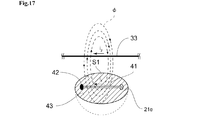
ICタグ検出部21eにおいても、ICタグ検出部21a〜21dと同様に、芯線41には、短絡状態にみられる大きな電流iが発生する。したがって、芯線41を流れる高周波電流iにより発生する磁界φは、図17に示されるように、金属部分で囲まれた内部空間S1内の充填材43が充填された部分を透過して、外部空間に広がる。図17に示されるように、ICタグ検出部21eの内部空間S1はモンキーレンチ1を貫通していない。そのため、くり貫かれた開口部分の方向にのみ、磁界φが広がる。そして、その磁界φのうちの少なくとも一部がコイルアンテナ33を貫通することにより、コイルアンテナ33に電流iが流れ、ICチップ32が動作するために必要な誘導電圧が発生し、ICチップ32が動作する。したがって、ICタグ検出部21eは、ICタグ3を検出し、情報を授受することができる。 Also in the IC tag detecting section 21e, as with the IC tag detecting section 21a to 21d, the core wire 41, a large current i 1 seen in a short-circuit condition occurs. Thus, the magnetic field φ generated by the high frequency current i 1 flowing through the core wire 41, as shown in FIG. 17, passes through the portion filled with the filler 43 in the internal space S1 surrounded by the metal part, the outside Spread in space. As shown in FIG. 17, the internal space S1 of the IC tag detection unit 21e does not penetrate the monkey wrench 1. Therefore, the magnetic field φ spreads only in the direction of the hollowed-out opening portion. Then, when at least a part of the magnetic field φ penetrates the coil antenna 33, a current i 2 flows through the coil antenna 33, an induced voltage required for the IC chip 32 to operate is generated, and the IC chip 32 is generated. Works. Therefore, the IC tag detection unit 21e can detect the IC tag 3 and exchange information.

また、ICタグ検出部21eを備えたモンキーレンチ1を右利きの作業者が使用している状態においては、作業者がICタグ検出部21eの位置を把握することは困難である。そこで、作業者が使用している状態で、ICタグ検出部21eの位置を把握することができるような目印をつけると好適である。図18に示されるように、ICタグ検出部21eにおいても、ICタグ検出部21bと同様に、目印61を、ICタグ検出部21cの芯線41の位置から少し離れた内部空間S1上に対応する位置に付けることにより、図10を用いて説明したように、ICタグ3の検出を確実に行うことが可能となる。 Further, when a right-handed worker is using the monkey wrench 1 provided with the IC tag detection unit 21e, it is difficult for the worker to grasp the position of the IC tag detection unit 21e. Therefore, it is preferable to add a mark so that the position of the IC tag detection unit 21e can be grasped while the operator is using it. As shown in FIG. 18, in the IC tag detection unit 21e as well, the mark 61 corresponds to the internal space S1 slightly separated from the position of the core wire 41 of the IC tag detection unit 21c, similarly to the IC tag detection unit 21b. By attaching it to the position, it is possible to reliably detect the IC tag 3 as described with reference to FIG.

ICタグ検出部21dとICタグ検出部21eにおいては、その内部空間S1の大きさおよび形状によって、通信感度が異なるとともに、モンキーレンチ1の対応する部分の強度も異なるものとなる。ICタグ検出部21dとICタグ検出部21eとを比較した場合、その通信感度は、ICタグ検出部21dの形状の方が優れている。しかしながら、モンキーレンチ1の対応する部分の強度は、ICタグ検出部21eの形状を用いた方が優れている。すなわち、ICタグ検出部21dとICタグ検出部21eのいずれをモンキーレンチ1に設けるかは、必要とされる通信感度と強度により定められるものとすることができる。 In the IC tag detection unit 21d and the IC tag detection unit 21e, the communication sensitivity differs depending on the size and shape of the internal space S1, and the strength of the corresponding portion of the monkey wrench 1 also differs. When the IC tag detection unit 21d and the IC tag detection unit 21e are compared, the communication sensitivity thereof is better in the shape of the IC tag detection unit 21d. However, the strength of the corresponding portion of the monkey wrench 1 is superior when the shape of the IC tag detection unit 21e is used. That is, which of the IC tag detection unit 21d and the IC tag detection unit 21e is provided on the monkey wrench 1 can be determined by the required communication sensitivity and strength.

なお、ICタグ検出部21a〜21eは、モンキーレンチ1に複数備えられていてもよいことは言うまでもない。 Needless to say, a plurality of IC tag detection units 21a to 21e may be provided in the monkey wrench 1.

次に、図19〜図23を参照して、タグ情報伝送部22について説明する。 Next, the tag information transmission unit 22 will be described with reference to FIGS. 19 to 23.

図19〜図21を参照して、タグ情報伝送部22の第1の例であるタグ情報伝送部22aについて説明する。 The tag information transmission unit 22a, which is a first example of the tag information transmission unit 22, will be described with reference to FIGS. 19 to 21.

図19は、図1における矢印Aの方向から見たモンキーレンチ1の上アゴ12の拡大斜視図である。モンキーレンチ1の上アゴ12から把持部13にかけての側面には、芯線41よりも太い溝65が形成されている。タグ情報伝送部22aにおいて、芯線41は、溝65内部であり、かつ、溝65の金属部分に接触しないように、リーダ/ライタ通信部23(図1参照)まで伸びている。 FIG. 19 is an enlarged perspective view of the upper jaw 12 of the monkey wrench 1 as viewed from the direction of the arrow A in FIG. A groove 65 thicker than the core wire 41 is formed on the side surface of the monkey wrench 1 from the upper jaw 12 to the grip portion 13. In the tag information transmission unit 22a, the core wire 41 extends to the reader / writer communication unit 23 (see FIG. 1) so as to be inside the groove 65 and not to come into contact with the metal portion of the groove 65.

タグ情報伝送部22aにおいては、図19に示されるように、工具の構造上、芯線41をICタグ検出部21の内部空間S1に突出させるために必要な部分のみ、金属内部をトンネル状に貫通して配線され、それ以外の多くの部分においては、モンキーレンチ1の上アゴ12から把持部13にかけての側面に沿って形成された溝65内部を配線されるように構成されている。モンキーレンチ1の側面に形成された溝65部分においては、図20に示されるように、芯線41が溝65の金属部分に接触しないように、樹脂等の絶縁物70が充填されている。(この構造を半同軸ケーブルと呼ぶこともある)また、その溝65の絶縁物がモンキーレンチ1の表面に露出している部分を、図21に示されるように、例えば、アルミなどの金属薄膜71で覆うことにより、すなわち、半同軸ケーブルを金属薄膜71で塞ぐことでよく知られた同軸ケーブルと同等の形状を形成することにより、タグ情報伝送部22aに対して外部からの電波雑音を遮断することができるようにすると好適である。 In the tag information transmission unit 22a, as shown in FIG. 19, only a portion necessary for projecting the core wire 41 into the internal space S1 of the IC tag detection unit 21 due to the structure of the tool penetrates the inside of the metal in a tunnel shape. In many other parts, the inside of the groove 65 formed along the side surface from the upper jaw 12 to the grip portion 13 of the monkey wrench 1 is configured to be wired. As shown in FIG. 20, the groove 65 portion formed on the side surface of the monkey wrench 1 is filled with an insulating material 70 such as resin so that the core wire 41 does not come into contact with the metal portion of the groove 65. (This structure is sometimes called a semi-coaxial cable.) Further, as shown in FIG. 21, the portion where the insulator of the groove 65 is exposed on the surface of the monkey wrench 1 is a metal thin film such as aluminum. By covering with 71, that is, by forming a shape equivalent to a well-known coaxial cable by covering the semi-coaxial cable with a metal thin film 71, the tag information transmission unit 22a is blocked from external radio noise. It is preferable to be able to do so.

次に、図22を参照して、タグ情報伝送部22の第2の例であるタグ情報伝送部22bについて説明する。 Next, the tag information transmission unit 22b, which is a second example of the tag information transmission unit 22, will be described with reference to FIG. 22.

タグ情報伝送部22bは、同軸ケーブルであり、芯線41が絶縁被覆81により覆われ、その外部が、外部導体82により覆われている。タグ情報伝送部22bがタグ情報伝送部22aと同様にモンキーレンチ1の側面に形成された溝65に配置される場合、溝65の金属部分に外部導体82が接することにより、アースを取ることが可能となるが、必要に応じて、外部導体82をモンキーレンチ1の金属部分のいずれかの位置に接続するようにしてもよい。 The tag information transmission unit 22b is a coaxial cable, the core wire 41 is covered with an insulating coating 81, and the outside thereof is covered with an outer conductor 82. When the tag information transmission unit 22b is arranged in the groove 65 formed on the side surface of the monkey wrench 1 like the tag information transmission unit 22a, the outer conductor 82 can be brought into contact with the metal portion of the groove 65 to be grounded. Although it is possible, if necessary, the outer conductor 82 may be connected to any position of the metal portion of the monkey wrench 1.

次に、図23を参照して、タグ情報伝送部22の第3の例であるタグ情報伝送部22cについて説明する。 Next, the tag information transmission unit 22c, which is a third example of the tag information transmission unit 22, will be described with reference to FIG. 23.

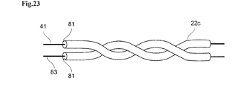
タグ情報伝送部22cは、導線を絶縁被覆で覆ったケーブルが2本縒り合されたツイストペアケーブルであり、その一方が、芯線41を絶縁被覆81で覆ったものであり、他方の導線83は、モンキーレンチ1の金属部分のいずれかの位置に接続される。タグ情報伝送部22cも、タグ情報伝送部22aおよびタグ情報伝送部22bと同様に、モンキーレンチ1の側面に形成された溝65に配置される。 The tag information transmission unit 22c is a twisted pair cable in which two cables whose lead wires are covered with an insulating coating are twisted together, one of which is a core wire 41 covered with an insulating coating 81, and the other lead wire 83 is a twisted pair cable. It is connected to any position on the metal part of the monkey wrench 1. The tag information transmission unit 22c is also arranged in the groove 65 formed on the side surface of the monkey wrench 1 in the same manner as the tag information transmission unit 22a and the tag information transmission unit 22b.

なお、タグ情報伝送部22cには、上述した以外にも、例えば、ストリップ経路(ストリップラインとも称される)や、リボンケーブルなどの、各種平行ケーブルを利用することが可能である。 In addition to the above, various parallel cables such as a strip path (also referred to as a strip line) and a ribbon cable can be used for the tag information transmission unit 22c.

なお、ここでは、モンキーレンチ1の上アゴ12から把持部13にかけての側面には、芯線41よりも太い溝65が形成され、その溝65内に、タグ情報伝送部22の多くの部分が配線されるものとして説明した。しかしながら、溝65の位置は、側面でなくともよく、モンキーレンチ1のいずれかの外周面に設けられていればよい。また、タグ情報伝送部22は、その全体、または、多くの部分が、モンキーレンチ1の上アゴ12から把持部13にかけての金属部分内部に形成されたトンネル状の貫通孔内を配線されるものとしてもよいし、その全体または多くの部分が、モンキーレンチ1の上アゴ12から把持部13にかけての外部側面に沿って配線されるものとしてもよい。 Here, a groove 65 thicker than the core wire 41 is formed on the side surface of the monkey wrench 1 from the upper jaw 12 to the grip portion 13, and many parts of the tag information transmission portion 22 are wired in the groove 65. Explained as being done. However, the position of the groove 65 does not have to be on the side surface, and may be provided on any outer peripheral surface of the monkey wrench 1. Further, the tag information transmission unit 22 is entirely or a large part of the tag information transmission unit 22 is wired in a tunnel-shaped through hole formed inside a metal portion from the upper jaw 12 to the grip portion 13 of the monkey wrench 1. However, the whole or many parts thereof may be wired along the outer side surface from the upper jaw 12 to the grip portion 13 of the monkey wrench 1.

なお、モンキーレンチ1は、多くの場合、その全体が金属製である。金属製の工具は、鍛造プレス形成により製造されることが多く、その側面または外周面に溝65を形成することは容易である。したがって、モンキーレンチ1の上アゴ12から把持部13にかけての側面に芯線41よりも太い溝65を形成し、その溝65内にタグ情報伝送部22を配置する形状は、タグ情報伝送部22の一部または全体を、モンキーレンチ1の上アゴ12から把持部13にかけての金属部分内部を通る場合と比較して、容易に製造可能であり、また、モンキーレンチ1の上アゴ12から把持部13にかけての外部側面に沿って配置される場合と比較して、利用者の作業の妨げにならないため好適である。 In many cases, the monkey wrench 1 is entirely made of metal. Metal tools are often manufactured by forging press forming, and it is easy to form a groove 65 on the side surface or the outer peripheral surface thereof. Therefore, the shape of the tag information transmission unit 22 is such that a groove 65 thicker than the core wire 41 is formed on the side surface of the monkey wrench 1 from the upper jaw 12 to the grip portion 13 and the tag information transmission unit 22 is arranged in the groove 65. A part or the whole can be easily manufactured as compared with the case where a part or the whole is passed through the inside of the metal portion from the upper jaw 12 to the grip portion 13 of the monkey wrench 1, and the upper jaw 12 to the grip portion 13 of the monkey wrench 1 can be manufactured. It is preferable because it does not interfere with the work of the user as compared with the case where it is arranged along the outer side surface of the wrench.

なお、ICタグ検出部21がモンキーレンチ1に複数備えられている場合、タグ情報伝送部22もICタグ検出部21と同数備えられることは言うまでもない。 When a plurality of IC tag detection units 21 are provided in the monkey wrench 1, it goes without saying that the same number of tag information transmission units 22 as the IC tag detection units 21 are provided.

次に、図24〜図34を参照して、リーダ/ライタ通信部23の詳細について説明する。 Next, the details of the reader / writer communication unit 23 will be described with reference to FIGS. 24 to 34.

図24〜図27を参照して、リーダ/ライタ通信部23の第1の例であるリーダ/ライタ通信部23aについて説明する。 The reader / writer communication unit 23a, which is a first example of the reader / writer communication unit 23, will be described with reference to FIGS. 24 to 27.

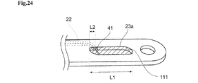
リーダ/ライタ通信部23aは、スロットアンテナ(スリットアンテナと称される場合もある)であり、モンキーレンチ1の金属製の把持部13に設けられた、通信波長の半波長の長さL1を有する細長いスリット状の貫通孔である。すなわち、この貫通孔は、スリットを形成する金属表面の内周を一巡する内周長が共振状態になるように形成されるのが好ましく、リーダ/ライタ通信部23aは、その内周長が通信波長とほぼ同じであるため、半波長共振する。リーダ/ライタ通信部23aにおいては、スリットのいずれかの端部から距離L2だけ離れた位置に、ICタグ検出部21およびタグ情報伝送部22の芯線41が突出し、芯線41の端部が、スリット内の金属部分の接続点101に、例えば、ハンダ付けなどにより電気的に接続されている。すなわち、芯線41の一端は接続点42に接続され、芯線41の他端は接続点101に接続されている。リーダ/ライタ端末4とリーダ/ライタ通信部23aとが通信するとき、リーダ/ライタ通信部23aのスリットは半波長共振するが、このとき、M点から距離L2だけ離れた芯線41とその接続点101は、スロットアンテナの給電部となる。そして、タグ情報伝送部22に高周波電流が供給されるとともに、スリット内周の金属部に高周波の電流が流れる。 The reader / writer communication unit 23a is a slot antenna (sometimes referred to as a slit antenna), and has a length L1 of a half wavelength of the communication wavelength provided in the metal grip portion 13 of the monkey wrench 1. It is an elongated slit-shaped through hole. That is, it is preferable that the through hole is formed so that the inner peripheral length that goes around the inner circumference of the metal surface forming the slit is in a resonance state, and the inner peripheral length of the reader / writer communication unit 23a communicates. Since it is almost the same as the wavelength, it resonates half a wavelength. In the reader / writer communication unit 23a, the core wire 41 of the IC tag detection unit 21 and the tag information transmission unit 22 protrudes at a position separated by a distance L2 from any end of the slit, and the end of the core wire 41 is a slit. It is electrically connected to the connection point 101 of the metal portion inside by, for example, soldering. That is, one end of the core wire 41 is connected to the connection point 42, and the other end of the core wire 41 is connected to the connection point 101. When the reader / writer terminal 4 and the reader / writer communication unit 23a communicate with each other, the slit of the reader / writer communication unit 23a resonates by half a wavelength. At this time, the core wire 41 separated from the point M by a distance L2 and its connection point. Reference numeral 101 denotes a feeding portion of the slot antenna. Then, a high-frequency current is supplied to the tag information transmission unit 22, and a high-frequency current flows through the metal portion on the inner circumference of the slit.

なお、リーダ/ライタ通信部23aのスリット長L1は通信波長のほぼ半波長と厳密に同じではなくても、同程度の長さであればよい。すなわち、リーダ/ライタ通信部23aのスリットの内周長も、通信波長と厳密に同じではなくても、同程度の長さであればよい。同程度の寸法には、多少の寸法的なばらつきが含まれるが、リーダ/ライタ通信部23aがスロットアンテナとして十分機能することができる範囲内であればよい。 The slit length L1 of the reader / writer communication unit 23a does not have to be exactly the same as the half wavelength of the communication wavelength, but may be the same length. That is, the inner peripheral length of the slit of the reader / writer communication unit 23a may not be exactly the same as the communication wavelength, but may be about the same length. The similar dimensions include some dimensional variations, but may be within a range in which the reader / writer communication unit 23a can sufficiently function as a slot antenna.

通信状態のリーダ/ライタ通信部23aにおいて、図26のM点およびN点では、半波長共振による定在波の電圧値は0である。そして、図26に示される方向で高周波電流iが流れている場合、K点の電圧値が最小(マイナスの値)となるときに、L点の電圧値は最大(プラスの値)となる。そして、高周波電流iの向きが逆転した時、K点の電圧値は最大(プラスの値)となり、L点の電圧値は最小(マイナスの値)となる。これにより磁界φが発生し、リーダ/ライタ端末4との情報の授受が可能となる。 In the reader / writer communication unit 23a in the communication state, the voltage value of the standing wave due to the half-wave resonance is 0 at the points M and N in FIG. When the high-frequency current i is flowing in the direction shown in FIG. 26, the voltage value at the L point becomes the maximum (plus value) when the voltage value at the K point becomes the minimum (minus value). Then, when the direction of the high frequency current i is reversed, the voltage value at the K point becomes the maximum (plus value), and the voltage value at the L point becomes the minimum (minus value). As a result, a magnetic field φ is generated, and information can be exchanged with the reader / writer terminal 4.

リーダ/ライタ通信部23aとリーダ/ライタ端末4とは、例えば、UHF帯の周波数920MHzの電波を用いて無線で通信することが可能である。この場合、リーダ/ライタ通信部23aのスリット長L1は16cmとなる。また、スリット幅は、例えば、通信波長の1/10程度であると好適であるが、把持部13に求められる強度等によりこの限りではなく、スリット長L1より充分小さい値、例えば、5mm〜1cm程度で、十分狭いことが望ましい。しかしながら、スリット幅が極端に細い場合、磁界の発生量が減少するため、通信精度が劣化してしまう恐れがある。スリット幅は工具の設計事情で決めることが望ましい。 The reader / writer communication unit 23a and the reader / writer terminal 4 can wirelessly communicate with each other using, for example, a radio wave having a frequency of 920 MHz in the UHF band. In this case, the slit length L1 of the reader / writer communication unit 23a is 16 cm. Further, the slit width is preferably about 1/10 of the communication wavelength, but is not limited to this depending on the strength required for the grip portion 13, and is a value sufficiently smaller than the slit length L1, for example, 5 mm to 1 cm. It is desirable that it is narrow enough. However, when the slit width is extremely narrow, the amount of magnetic field generated is reduced, which may deteriorate the communication accuracy. It is desirable to determine the slit width according to the design circumstances of the tool.

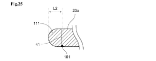
また、図25の拡大図に示されるように、給電部となる芯線41とスリット端部との距離L2は、電磁気学的に、リーダ/ライタ端末4によるICタグ3の検出感度が最大となるように調整整合することが望ましい。L2は、例えば、スリット幅と同程度としてもよい。 Further, as shown in the enlarged view of FIG. 25, the distance L2 between the core wire 41 serving as the power feeding portion and the slit end portion electromagnetically maximizes the detection sensitivity of the IC tag 3 by the reader / writer terminal 4. It is desirable to adjust and align as such. L2 may be, for example, about the same as the slit width.

また、リーダ/ライタ通信部23aのスリット部に、ゴミ等が入り込むと、最悪の場合、図26を用いて説明した、スリット内周を流れる高周波電流がショートしてしまい、それによって通信精度が劣化してしまう虞がある。かかるショートを防止するため、例えば、樹脂等の、電気伝導性を有さず、磁界を透過する材質による充填材111を充填すると好適である。 Further, if dust or the like enters the slit portion of the reader / writer communication unit 23a, in the worst case, the high frequency current flowing through the inner circumference of the slit described with reference to FIG. 26 is short-circuited, which deteriorates the communication accuracy. There is a risk of doing so. In order to prevent such a short circuit, it is preferable to fill the filler 111 with a material that does not have electrical conductivity and transmits a magnetic field, such as resin.

なお、不透明な充填材111を充填した場合、芯線41および接続点101は外部空間から見えなくなるが、その位置などを説明するため、各図面においては、充填材111を透過して芯線41および接続点101を図示し、説明するものとする。 When the opaque filler 111 is filled, the core wire 41 and the connection point 101 cannot be seen from the external space, but in order to explain the positions and the like, in each drawing, the core wire 41 and the connection point 101 are connected through the filler 111. Point 101 shall be illustrated and described.

また、上述したように、リーダ/ライタ通信部23aにおいては、図26を用いて説明したK点およびL点における電圧の絶対値は最大となるので、モンキーレンチ1の把持部13の対応する部分を作業者が把持することによって、作業者の手により、スリット内周を流れる高周波電流がショートしてしまうことを防止することが望ましい。したがって、図27に示されるように、例えば、樹脂等の、電気伝導性を有さず、磁界を透過する材質により構成されたグリップ112を設けるようにすると、スロットアンテナの感度も高く、好適である。なお、グリップ112は、スリットの全体を覆うように構成することもできる。グリップ112の材質には、媒質定数が1に近い物質を選定すると好適である。このグリップ112は、リーダ/ライタ通信部23aのスリット部に、ゴミ等が入り込むことを防いで、スリット内周を流れる高周波電流がショートしてしまうことなどによって通信精度が劣化してしまうことを防止することができるとともに、把持部13の滑り止めにもなり、作業者の使用感の向上にもつながる。 Further, as described above, in the reader / writer communication unit 23a, since the absolute value of the voltage at the points K and L described with reference to FIG. 26 is the maximum, the corresponding portion of the grip portion 13 of the monkey wrench 1 is obtained. It is desirable to prevent the high-frequency current flowing through the inner circumference of the slit from being short-circuited by the operator's hand by grasping the above. Therefore, as shown in FIG. 27, it is preferable to provide the grip 112 made of a material that does not have electrical conductivity and transmits a magnetic field, such as resin, because the sensitivity of the slot antenna is high. is there. The grip 112 can also be configured to cover the entire slit. It is preferable to select a substance having a medium constant close to 1 as the material of the grip 112. This grip 112 prevents dust and the like from entering the slit portion of the reader / writer communication unit 23a, and prevents the communication accuracy from deteriorating due to a short circuit of the high frequency current flowing through the inner circumference of the slit. In addition to this, the grip portion 13 can be prevented from slipping, which leads to an improvement in the usability of the operator.

また、モンキーレンチ1の把持部13の大きさや必要とされる強度によっては、通信波長の半波長の長さL1を有するスリット状の貫通孔を設けることが困難な場合もある。以下に、そのような場合についての構成例を説明する。 Further, depending on the size of the grip portion 13 of the monkey wrench 1 and the required strength, it may be difficult to provide a slit-shaped through hole having a length L1 of a half wavelength of the communication wavelength. A configuration example for such a case will be described below.

図28を参照して、リーダ/ライタ通信部23の第2の例であるリーダ/ライタ通信部23bについて説明する。また、図29を参照して、リーダ/ライタ通信部23の第3の例であるリーダ/ライタ通信部23cについて説明する。 The reader / writer communication unit 23b, which is a second example of the reader / writer communication unit 23, will be described with reference to FIG. 28. Further, the reader / writer communication unit 23c, which is a third example of the reader / writer communication unit 23, will be described with reference to FIG. 29.

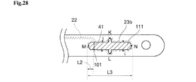
図28に示されるリーダ/ライタ通信部23b、および、図29に示されるリーダ/ライタ通信部23cは、リーダ/ライタ通信部23aと同様のスロットアンテナであるが、モンキーレンチ1の金属製の把持部13に設けられる貫通孔は直線状のスリットではなく、貫通孔の側面の少なくとも一部に凹凸を有する形状であって、そのスリットを形成する金属表面の内周を一巡する内周長が、通信波長の半波長の長さL1の2倍(換言すれば、通信波長)と同程度の長さを有するため、スロットアンテナと同様の半波長共振の条件を維持することが可能となる。 The reader / writer communication unit 23b shown in FIG. 28 and the reader / writer communication unit 23c shown in FIG. 29 are slot antennas similar to the reader / writer communication unit 23a, but grip the monkey wrench 1 made of metal. The through hole provided in the portion 13 is not a straight slit, but has a shape having irregularities on at least a part of the side surface of the through hole, and the inner circumference length that goes around the inner circumference of the metal surface forming the slit is determined. Since the length is about twice the length L1 of the half wavelength of the communication wavelength (in other words, the communication wavelength), it is possible to maintain the same half-wavelength resonance condition as that of the slot antenna.

図28に示されるリーダ/ライタ通信部23bは、把持部13に設けられる貫通孔を、十字型としている。この場合、図24を用いて説明したリーダ/ライタ通信部23aに対して、通信感度が劣ってしまうが、把持部13の長さ方向の端点Mと端点Nとの距離を、スリット長L1よりも短いL3とすることが可能である。リーダ/ライタ通信部23bは、いずれかの端部(長手方向の端部)から距離L2だけ離れた位置に、ICタグ検出部21およびタグ情報伝送部22の芯線41が突出し、芯線41の端部が、スリット内の金属部分の接続点101に、例えば、ハンダ付けなどにより電気的に接続されている。 The reader / writer communication unit 23b shown in FIG. 28 has a cross-shaped through hole provided in the grip portion 13. In this case, the communication sensitivity is inferior to that of the reader / writer communication unit 23a described with reference to FIG. 24, but the distance between the end point M and the end point N in the length direction of the grip portion 13 is set from the slit length L1. Can also be a short L3. In the reader / writer communication unit 23b, the core wire 41 of the IC tag detection unit 21 and the tag information transmission unit 22 protrudes from one of the ends (end in the longitudinal direction) by a distance L2, and the end of the core wire 41 The portion is electrically connected to the connection point 101 of the metal portion in the slit by, for example, soldering.

リーダ/ライタ端末4とリーダ/ライタ通信部23bとが通信するとき、芯線41は、スロットアンテナの給電部となり、タグ情報伝送部22に高周波電流が供給されるとともに、スリット内周の金属部に高周波の電流が流れる。通信状態のリーダ/ライタ通信部23bにおいて、図28のM点およびN点では、電圧値は0である。そして、図28に示される方向で高周波電流iが流れている場合、K点の電圧値が最小(マイナスの値)となるときに、L点の電圧値は最大(プラスの値)となる。そして、高周波電流iの向きが逆転した時、K点の電圧値は最大(プラスの値)となり、L点の電圧値は最小(マイナスの値)となる。 When the reader / writer terminal 4 and the reader / writer communication unit 23b communicate with each other, the core wire 41 serves as a power supply unit for the slot antenna, a high-frequency current is supplied to the tag information transmission unit 22, and a metal portion on the inner circumference of the slit is supplied. High frequency current flows. In the reader / writer communication unit 23b in the communication state, the voltage value is 0 at the points M and N in FIG. 28. When the high-frequency current i is flowing in the direction shown in FIG. 28, the voltage value at the L point becomes the maximum (plus value) when the voltage value at the K point becomes the minimum (minus value). Then, when the direction of the high frequency current i is reversed, the voltage value at the K point becomes the maximum (plus value), and the voltage value at the L point becomes the minimum (minus value).

リーダ/ライタ通信部23bとリーダ/ライタ端末4とは、例えば、周波数920MHzの電波を用いて無線で通信することが可能である。この場合、リーダ/ライタ通信部23bの十字型スリットの内周を一巡する長さは32cmとなり、リーダ/ライタ通信部23aのスリットの内周を一巡する長さと等しい。 The reader / writer communication unit 23b and the reader / writer terminal 4 can communicate wirelessly using, for example, a radio wave having a frequency of 920 MHz. In this case, the length that goes around the inner circumference of the cross-shaped slit of the reader / writer communication unit 23b is 32 cm, which is equal to the length that goes around the inner circumference of the slit of the reader / writer communication unit 23a.

なお、リーダ/ライタ通信部23bのスリットの内周長は、通信波長と厳密に同じではなくても、同程度の長さであればよい。同程度の寸法には、多少の寸法的なばらつきが含まれるが、リーダ/ライタ通信部23bがスロットアンテナとして十分機能することができる範囲内であればよい。 The inner peripheral length of the slit of the reader / writer communication unit 23b may not be exactly the same as the communication wavelength, but may be about the same length. The similar dimensions include some dimensional variations, but may be within a range in which the reader / writer communication unit 23b can sufficiently function as a slot antenna.

また、リーダ/ライタ通信部23bにおいても、そのスリット部に、ゴミ等が入り込まないように、例えば、樹脂等の、電気伝導性を有さず、磁界を透過する充填材111により、スリット内部を充填すると好適である。さらに、モンキーレンチ1を作業者が把持することによって、作業者の手により高周波電流がショートしてしまうことがないように、図27を用いて説明した場合と同様のグリップ112を設けると好適である。 Further, also in the reader / writer communication unit 23b, the inside of the slit is filled with a filler 111 such as resin, which does not have electrical conductivity and transmits a magnetic field, so that dust or the like does not enter the slit portion. It is suitable to fill. Further, it is preferable to provide a grip 112 similar to the case described with reference to FIG. 27 so that the operator does not short-circuit the high-frequency current by the operator's hand when the monkey wrench 1 is gripped by the operator. is there.

また、モンキーレンチ1の把持部13の大きさや必要とされる強度によっては、図28を用いて説明したリーダ/ライタ通信部23bよりも、更に、短いスリット長とすることを求められる場合もある。 Further, depending on the size of the grip portion 13 of the monkey wrench 1 and the required strength, it may be required to have a slit length shorter than that of the reader / writer communication portion 23b described with reference to FIG. 28. ..

図29に示されるリーダ/ライタ通信部23cは、把持部13に設けられる貫通孔の凹部分を2か所としている(キの字型としている)。それにより、図28を用いて説明したリーダ/ライタ通信部23bに対して、さらに通信感度が劣ってしまうが、把持部13の長さ方向の端点Mと端点Nとの距離を、スリット長L3よりも更に短いL4とすることができる。図29に示されるリーダ/ライタ通信部23cは、M点またはN点のいずれかの端部(長手方向の端部)から距離L2だけ離れた位置に、ICタグ検出部21およびタグ情報伝送部22の芯線41が突出し、芯線41の端部が、スリット内の金属部分の接続点101に、例えば、ハンダ付けなどにより電気的に接続されている。 The reader / writer communication unit 23c shown in FIG. 29 has two recessed portions of the through holes provided in the grip portion 13 (in a K-shape). As a result, the communication sensitivity is further inferior to that of the reader / writer communication unit 23b described with reference to FIG. 28, but the distance between the end point M and the end point N in the length direction of the grip portion 13 is set to the slit length L3. It can be L4, which is even shorter than that. The reader / writer communication unit 23c shown in FIG. 29 is located at a position separated by a distance L2 from the end (end in the longitudinal direction) of either the M point or the N point, and is the IC tag detection unit 21 and the tag information transmission unit. The core wire 41 of 22 protrudes, and the end portion of the core wire 41 is electrically connected to the connection point 101 of the metal portion in the slit by, for example, soldering.

リーダ/ライタ端末4とリーダ/ライタ通信部23とが通信するとき、M点から距離L2だけ離れた芯線41とその接続点101は、スロットアンテナの給電部となり、タグ情報伝送部22に高周波電流が供給されるとともに、スリット内周の金属部に高周波の電流が流れる。通信状態のリーダ/ライタ通信部23cにおいて、図29のM点およびN点では、電圧値は0である。そして、図29に示される方向で高周波電流iが流れている場合、K点の電圧値が最小(マイナスの値)となるときに、L点の電圧値は最大(プラスの値)となる。そして、高周波電流iの向きが逆転した時、K点の電圧値は最大(プラスの値)となり、L点の電圧値は最小(マイナスの値)となる。 When the reader / writer terminal 4 and the reader / writer communication unit 23 communicate with each other, the core wire 41 and its connection point 101, which are separated from the M point by a distance L2, serve as a feeding unit for the slot antenna, and a high-frequency current is applied to the tag information transmission unit 22. Is supplied, and a high-frequency current flows through the metal part on the inner circumference of the slit. In the reader / writer communication unit 23c in the communication state, the voltage value is 0 at the points M and N in FIG. 29. When the high-frequency current i is flowing in the direction shown in FIG. 29, the voltage value at the L point becomes the maximum (plus value) when the voltage value at the K point becomes the minimum (minus value). Then, when the direction of the high frequency current i is reversed, the voltage value at the K point becomes the maximum (plus value), and the voltage value at the L point becomes the minimum (minus value).

リーダ/ライタ通信部23cとリーダ/ライタ端末4とは、例えば、周波数920MHzの電波を用いて無線で通信することが可能である。この場合も、リーダ/ライタ通信部23cのスリットの内周を一巡する長さは32cmとなる。 The reader / writer communication unit 23c and the reader / writer terminal 4 can communicate wirelessly using, for example, a radio wave having a frequency of 920 MHz. Also in this case, the length that goes around the inner circumference of the slit of the reader / writer communication unit 23c is 32 cm.

なお、リーダ/ライタ通信部23cのスリットの内周長は、通信波長と厳密に同じではなくても、同程度の長さであればよい。同程度の寸法には、多少の寸法的なばらつきが含まれるが、リーダ/ライタ通信部23cがスロットアンテナとして十分機能することができる範囲内であればよい。 The inner peripheral length of the slit of the reader / writer communication unit 23c does not have to be exactly the same as the communication wavelength, but may be about the same length. The similar dimensions include some dimensional variations, but may be within a range in which the reader / writer communication unit 23c can sufficiently function as a slot antenna.

また、リーダ/ライタ通信部23cにおいても、そのスリット部に、ゴミ等が入り込まないように、例えば、樹脂等の、電気伝導性を有さず、磁界を透過する充填材111により、スリット内部を充填すると好適である。さらに、モンキーレンチ1を作業者が把持することによって、作業者の手により高周波電流がショートしてしまうことがないように、図27を用いて説明した場合と同様のグリップ112を設けると好適である。 Further, also in the reader / writer communication unit 23c, the inside of the slit is filled with a filler 111 such as resin, which does not have electrical conductivity and transmits a magnetic field, so that dust or the like does not enter the slit portion. It is suitable to fill. Further, it is preferable to provide a grip 112 similar to the case described with reference to FIG. 27 so that the operator does not short-circuit the high-frequency current by the operator's hand when the monkey wrench 1 is gripped by the operator. is there.

また、モンキーレンチ1の把持部13の大きさや必要とされる強度によっては、上述したリーダ/ライタ通信部23a〜cよりも、更に、短いスリット長とすることを求められる場合もある。 Further, depending on the size of the grip portion 13 of the monkey wrench 1 and the required strength, it may be required to have a slit length shorter than that of the reader / writer communication portions 23a to 23c described above.

次に、図30を参照して、リーダ/ライタ通信部23の第4の例であるリーダ/ライタ通信部23dについて説明する。 Next, the reader / writer communication unit 23d, which is a fourth example of the reader / writer communication unit 23, will be described with reference to FIG.

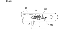
図30に示されるリーダ/ライタ通信部23dは、図29を用いて説明したリーダ/ライタ通信部23cと同様に、把持部13に設けられる貫通孔の凹部分を2か所としている。これとともに、スリットの内部に、媒質定数が真空や空気と比較して高い値の絶縁物の充填材115を充填することにより、把持部13の長さ方向の端点Mと端点Nとの距離を、図29を用いて説明したリーダ/ライタ通信部23cのスリット長L4よりも更に短いL5としている。図30に示されるリーダ/ライタ通信部23dにおいても、いずれかの端部(長手方向の端部)から距離L2だけ離れた位置に、ICタグ検出部21およびタグ情報伝送部22の芯線41が突出し、芯線41の端部が、スリット内の金属部分の接続点101に、例えば、ハンダ付けなどにより電気的に接続されている。 The reader / writer communication unit 23d shown in FIG. 30 has two recessed portions of the through holes provided in the grip portion 13, similarly to the reader / writer communication unit 23c described with reference to FIG. 29. At the same time, by filling the inside of the slit with a filler 115, which is an insulator having a medium constant higher than that of vacuum or air, the distance between the end point M and the end point N in the length direction of the grip portion 13 can be increased. , L5 is shorter than the slit length L4 of the reader / writer communication unit 23c described with reference to FIG. 29. Also in the reader / writer communication unit 23d shown in FIG. 30, the core wire 41 of the IC tag detection unit 21 and the tag information transmission unit 22 is located at a position separated by a distance L2 from any end (end in the longitudinal direction). The protruding end of the core wire 41 is electrically connected to the connection point 101 of the metal portion in the slit, for example, by soldering.

通信状態のリーダ/ライタ通信部23dにおいても、図30のM点およびN点では、電圧値は0である。そして、図30に示される方向で高周波電流iが流れている場合、K点の電圧値が最小(マイナスの値)となるときに、L点の電圧値は最大(プラスの値)となる。そして、高周波電流iの向きが逆転した時、K点の電圧値は最大(プラスの値)となり、L点の電圧値は最小(マイナスの値)となる。 Even in the reader / writer communication unit 23d in the communication state, the voltage value is 0 at the points M and N in FIG. When the high-frequency current i is flowing in the direction shown in FIG. 30, the voltage value at the L point becomes the maximum (plus value) when the voltage value at the K point becomes the minimum (minus value). Then, when the direction of the high frequency current i is reversed, the voltage value at the K point becomes the maximum (plus value), and the voltage value at the L point becomes the minimum (minus value).

媒質定数は、比誘電率と比透磁率との積で表される。真空中の比誘電率εは1.0であり、比透磁率μは1.0であるため、真空中の媒質定数は1.0となる。また、空気中の媒質定数も、ほぼ1.0である。充填材115の媒質定数は、その材質の比誘電率と比透磁率とが、真空に対してそれぞれ何倍であるかにより求められる。すなわち、充填材115の材質の比誘電率が真空のn倍であり、比透磁率が真空のm倍である場合、充填材115の媒質定数は、mnεμで表される。したがって、スリットの内部が充填材115で充填されている場合の波長には、次の数式(3)で示される値が積算される。 The medium constant is represented by the product of the relative permittivity and the relative magnetic permeability. Since the relative permittivity ε in vacuum is 1.0 and the relative permeability μ is 1.0, the medium constant in vacuum is 1.0. The medium constant in air is also approximately 1.0. The medium constant of the filler 115 is determined by how many times the relative permittivity and the relative magnetic permeability of the material are with respect to vacuum. That is, when the relative permittivity of the material of the filler 115 is n times the vacuum and the relative magnetic permeability is m times the vacuum, the medium constant of the filler 115 is represented by mnεμ. Therefore, the value represented by the following mathematical formula (3) is integrated into the wavelength when the inside of the slit is filled with the filler 115.

数式(3)

Figure 0006861411
Formula (3)
Figure 0006861411

充填材115の材質は、抵抗ロスなどによりアンテナ感度を下げることのない物質が望ましく、例えば、空気を多く含むウレタン材やフッ素樹脂などの他に、塩化樹脂や高分子樹脂などを用いることができる。これらの樹脂は、nが2〜5、mがほぼ1であり、例えば、m×nが4である物質を充填材115として用いた場合、スリットの内周を一巡する長さは、リーダ/ライタ通信部23a〜cの半分でよい。例えば、リーダ/ライタ通信部23dとリーダ/ライタ端末4とが、UHF帯の周波数920MHzの電波を用いて通信した場合、リーダ/ライタ通信部23dのスリットの内周を一巡する長さは、16cmとなる。 The material of the filler 115 is preferably a substance that does not lower the antenna sensitivity due to resistance loss or the like. For example, in addition to urethane material and fluororesin containing a large amount of air, chloride resin and polymer resin can be used. .. In these resins, n is 2 to 5 and m is approximately 1, for example, when a substance having m × n of 4 is used as the filler 115, the length of one round of the inner circumference of the slit is determined by the reader /. Half of the writer communication units 23a to 23c may be used. For example, when the reader / writer communication unit 23d and the reader / writer terminal 4 communicate using radio waves having a frequency of 920 MHz in the UHF band, the length of the inner circumference of the slit of the reader / writer communication unit 23d is 16 cm. It becomes.

なお、リーダ/ライタ通信部23aまたはリーダ/ライタ通信部23bと同様の形状のスリットに対して、スリット内を充填材115により充填することにより把持部13の長さ方向のスリット長を短くすることができるのは言うまでもない。リーダ/ライタ通信部23aと同様の形状のスリットに対して、スリット内を、m×nが4である物質の充填材115により充填した場合、そのスロット長は8cmとなり、リーダ/ライタ通信部23bと同様の形状のスリットに対して、スリット内を、m×nが4である物質の充填材115により充填した場合、そのスリットの内周を一巡する長さは、16cmとなる。 For a slit having the same shape as the reader / writer communication unit 23a or the reader / writer communication unit 23b, the slit length in the length direction of the grip portion 13 is shortened by filling the inside of the slit with the filler 115. Needless to say, you can do it. When the inside of the slit is filled with a filler 115 of a substance having m × n of 4 for a slit having the same shape as the reader / writer communication unit 23a, the slot length is 8 cm, and the reader / writer communication unit 23b When the inside of the slit is filled with a filler 115 made of a substance having m × n of 4, the length of the slit that goes around the inner circumference of the slit is 16 cm.

また、リーダ/ライタ通信部23dにおいても、モンキーレンチ1を作業者が把持することによって、作業者の手により高周波電流がショートしてしまうことがないように、図27を用いて説明した場合と同様のグリップ112を設けると好適である。 Further, also in the reader / writer communication unit 23d, the case where the high frequency current is not short-circuited by the operator's hand when the monkey wrench 1 is gripped by the operator is described with reference to FIG. 27. It is preferable to provide a similar grip 112.

以上説明したリーダ/ライタ通信部23a〜23dにおいては、スリットのいずれか一端に芯線41を突出させ、接続部101を用いてスリット壁面の金属部分に短絡させることにより給電部を一か所構成し、リーダ/ライタ端末4と通信するものとして説明した。しかしながら、リーダ/ライタ通信部23a〜23dは、そのスリットの両端(M点側とN点側)において、給電部を形成することが可能である。このような構成にした場合、一つのスリットで2つの給電部を構成することが可能となり、2つのICタグ検出部21を1つのリーダ/ライタ通信部23に集約して接続することが可能である。 In the reader / writer communication units 23a to 23d described above, the core wire 41 is projected from one end of the slit, and the connection portion 101 is used to short-circuit the metal portion on the wall surface of the slit to form one power supply unit. , It has been described as communicating with the reader / writer terminal 4. However, the reader / writer communication units 23a to 23d can form power feeding units at both ends (M point side and N point side) of the slit. With such a configuration, it is possible to configure two power feeding units with one slit, and it is possible to collectively connect the two IC tag detection units 21 to one reader / writer communication unit 23. is there.

次に、図31〜図33を参照して、リーダ/ライタ通信部23の第5の例であるリーダ/ライタ通信部23e、および、リーダ/ライタ通信部23の第6の例であるリーダ/ライタ通信部23fについて説明する。 Next, with reference to FIGS. 31 to 33, the reader / writer communication unit 23e, which is a fifth example of the reader / writer communication unit 23, and the reader / writer communication unit 23, which is a sixth example of the reader / writer communication unit 23. The writer communication unit 23f will be described.

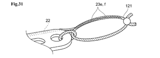
モンキーレンチ1等の工具は、例えば、工具の落下防止や、工具を吊り下げて収納するためなどに、その一部に紐(ストラップ)がつけられる場合がある。そこで、図31に示されるように、モンキーレンチ1にあらかじめ紐121を備え付け、タグ情報伝送部22を、その紐121の内部まで伸ばし、リーダ/ライタ通信部23e、および、リーダ/ライタ通信部23fを、紐121内に設けるものとする。紐121は、電気伝導性を有さず、磁界を透過させることができる素材で構成される。 A string (strap) may be attached to a part of a tool such as a monkey wrench 1 in order to prevent the tool from falling or to suspend and store the tool. Therefore, as shown in FIG. 31, a string 121 is provided in advance on the monkey wrench 1, the tag information transmission unit 22 is extended to the inside of the string 121, and the reader / writer communication unit 23e and the reader / writer communication unit 23f are extended. Is provided in the string 121. The string 121 is made of a material that does not have electrical conductivity and is capable of transmitting a magnetic field.

図32を用いてリーダ/ライタ通信部23eについて説明する。リーダ/ライタ通信部23eは、ダイポールアンテナであり、紐121内のタグ情報伝送部22の、例えば、図22の芯線41および外部導体82、または、図23の芯線41および導線83の先端部分から、それぞれ連続的に、線状、または、細長い板状で、その長さがそれぞれ通信波長のλ/4となる伝導体を両方向に伸ばしたものである。 The reader / writer communication unit 23e will be described with reference to FIG. 32. The reader / writer communication unit 23e is a dipole antenna, and is from the tip portion of the tag information transmission unit 22 in the string 121, for example, the core wire 41 and the outer conductor 82 in FIG. 22 or the core wire 41 and the conductor wire 83 in FIG. 23. , Each of which is a continuous linear or elongated plate-shaped conductor whose length is λ / 4 of the communication wavelength and is extended in both directions.

図33を参照して、リーダ/ライタ通信部23fについて説明する。リーダ/ライタ通信部23fは、モノポールアンテナであり、紐121内のタグ情報伝送部22の先端部分の芯線41のみを、線状、または、細長い板状で、その長さが通信波長のλ/4となる伝導体を一方向に伸ばしたものである。 The reader / writer communication unit 23f will be described with reference to FIG. 33. The reader / writer communication unit 23f is a monopole antenna, and only the core wire 41 at the tip of the tag information transmission unit 22 in the string 121 is linear or elongated plate-shaped, and the length thereof is λ of the communication wavelength. It is a conductor that becomes 4/4 extended in one direction.

このように、リーダ/ライタ通信部23がリーダ/ライタ端末4と無線で通信を行う場合、リーダ/ライタ端末4に対してモンキーレンチ1を独立して使用することができるため、作業性を向上させることが可能となる。 In this way, when the reader / writer communication unit 23 wirelessly communicates with the reader / writer terminal 4, the monkey wrench 1 can be used independently for the reader / writer terminal 4, thus improving workability. It becomes possible to make it.

また、リーダ/ライタ通信部23は、有線による通信を行うものであってもよいことは言うまでもない。図34を用いて、リーダ/ライタ通信部23の第7の例であるリーダ/ライタ通信部23gについて説明する。図34に示されるように、タグ情報伝送部22の端部と、同軸ケーブルやツイストペアケーブル等のケーブルにより構成されるリーダライタ通信部23gの端部を電気的に接続し、リーダ/ライタ端末4の所定のポートに接続することにより、情報を授受するものとしてもよい。リーダ/ライタ通信部23gを用いて、有線でリーダ/ライタ端末4と通信を行う場合、無線で通信を行う場合と比較して、通信を安定して行うことが可能となる。 Needless to say, the reader / writer communication unit 23 may perform wired communication. The reader / writer communication unit 23g, which is a seventh example of the reader / writer communication unit 23, will be described with reference to FIG. 34. As shown in FIG. 34, the end of the tag information transmission unit 22 and the end of the reader / writer communication unit 23g composed of a cable such as a coaxial cable or a twisted pair cable are electrically connected, and the reader / writer terminal 4 Information may be exchanged by connecting to a predetermined port of. When communicating with the reader / writer terminal 4 by wire using the reader / writer communication unit 23g, it is possible to perform stable communication as compared with the case of wireless communication.

なお、ICタグ検出部21およびタグ情報伝送部22がモンキーレンチ1に複数備えられている場合、リーダ/ライタ通信部23もICタグ検出部21と同数備えられることは言うまでもない。また、ICタグ検出部21およびタグ情報伝送部22がモンキーレンチ1に複数備えられている場合、少なくとも1つのリーダ/ライタ通信部23のスリットの両端(M点側とN点側)に給電部を形成することにより、2つのICタグ検出部21を1つのリーダ/ライタ通信部23に集約して接続する構成とすると好適である。 When a plurality of IC tag detection units 21 and tag information transmission units 22 are provided in the monkey wrench 1, it goes without saying that the same number of reader / writer communication units 23 as those of the IC tag detection units 21 are provided. When the monkey wrench 1 is provided with a plurality of IC tag detection units 21 and tag information transmission units 22, power supply units are supplied to both ends (M point side and N point side) of slits of at least one reader / writer communication unit 23. It is preferable that the two IC tag detection units 21 are aggregated and connected to one reader / writer communication unit 23 by forming the above.

このような構成を有すモンキーレンチ1を用いることにより、ICタグ3を検出する動作と、モンキーレンチ1によりボルト2を取り付ける、または、取り外す動作との間に、モンキーレンチ1とリーダ/ライタ端末4とを持ち替える必要がなくなるため、作業が煩雑になることなく、モンキーレンチ1により取り付けられるまたは取り外されるボルト2を管理することが可能となる。 By using the monkey wrench 1 having such a configuration, the monkey wrench 1 and the reader / writer terminal can be inserted between the operation of detecting the IC tag 3 and the operation of attaching or removing the bolt 2 by the monkey wrench 1. Since it is not necessary to change the position with 4, it is possible to manage the bolt 2 attached or detached by the monkey wrench 1 without complicating the work.

以上の説明においては、モンキーレンチ1の上アゴ12が金属製であるものとして説明したが、例えば、他の部分が金属製であってもよく、その場合は、金属製である部分にICタグ検出部21を設けるものとする。また、以上の説明においては、モンキーレンチ1の把持部13が金属製であるものとして説明したが、例えば、他の部分が金属製であってもよく、その場合は、金属製である部分にリーダライタ通信部23を設けるものとする。 In the above description, the upper jaw 12 of the monkey wrench 1 has been described as being made of metal. However, for example, the other part may be made of metal. In that case, the IC tag is attached to the part made of metal. The detection unit 21 shall be provided. Further, in the above description, the grip portion 13 of the monkey wrench 1 has been described as being made of metal, but for example, the other portion may be made of metal, and in that case, the portion made of metal is used. A reader / writer communication unit 23 shall be provided.

また、以上においては、工具に対応するものとして、モンキーレンチを例として説明したが、本発明は、モンキーレンチ以外にも、例えば、メガネレンチ、トルクレンチ、ドライバー、ボックスドライバー、ペンチ、ニッパー、ワイヤーストリッパー、その他の、少なくとも一部に金属を有する工具に適用することができる。 Further, in the above, the monkey wrench has been described as an example as corresponding to the tool, but the present invention includes, for example, a box wrench, a torque wrench, a screwdriver, a box driver, pliers, a nipper, and a wire in addition to the monkey wrench. It can be applied to strippers and other tools that have metal at least in part.

例えば、ワイヤーハーネスの被覆の先端部分を削除するワイヤーストリッパーは、対象となるワイヤーハーネスの太さや被覆の材質によって、使用するものが異なる場合がある。このような場合に、ワイヤーハーネスが撒きつけられたリール等に、ワイヤーハーネスの長さや被覆の材質などを示す情報が記録されたICタグ3を取り付け、ワイヤーストリッパーに、上述したICタグ検出部21、タグ情報伝送部22、および、リーダ/ライタ通信部23を設ける。そして、作業前に、ICタグ3に記録された情報を読み取り、使用するワイヤーストリッパーの種類と適合しているか否かを判断することができるようにした場合、ワイヤーハーネスの太さや被覆の材質に合致しないワイヤーストリッパーで被覆を削除してしまい、被覆が削除しきれずに残ってしまったり、芯線部分を削ってしまうことを防止することが可能となる。 For example, the wire stripper that removes the tip portion of the coating of the wire harness may be used differently depending on the thickness of the target wire harness and the material of the coating. In such a case, an IC tag 3 in which information indicating the length of the wire harness and the material of the coating is recorded is attached to a reel or the like on which the wire harness is sprinkled, and the IC tag detection unit 21 described above is attached to the wire stripper. , The tag information transmission unit 22 and the reader / writer communication unit 23 are provided. Then, before starting work, if the information recorded on the IC tag 3 can be read and it can be determined whether or not the wire stripper is compatible with the type of wire stripper to be used, the thickness of the wire harness and the material of the coating can be used. It is possible to prevent the coating from being removed by a wire stripper that does not match, and the coating cannot be completely removed and remains, or the core wire portion is scraped.

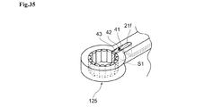
また、例えば、メガネレンチなど、工具の構成上、金属部分で囲まれた貫通孔をあらかじめ有している工具に対しては、その貫通孔の内側に対して、更に切り欠きを加えることにより、内部空間S1を形成するものとしてもよい。そこで、ICタグ検出部21を備える他の工具として、図35のメガネレンチ125について説明する。メガネレンチ125は工具に対応する。図35は、メガネレンチ125を裏返しにした(メガネレンチ125を右利きの作業者が使用している状態において裏となる面を上面とした)場合のICタグ検出部21fの拡大斜視図である。 Further, for a tool such as a box wrench that has a through hole surrounded by a metal portion in advance due to the structure of the tool, a notch is further added to the inside of the through hole. It may form the internal space S1. Therefore, as another tool including the IC tag detection unit 21, the box wrench 125 of FIG. 35 will be described. The box wrench 125 corresponds to a tool. FIG. 35 is an enlarged perspective view of the IC tag detection unit 21f when the spectacle wrench 125 is turned inside out (the back surface is the upper surface when the spectacle wrench 125 is used by a right-handed worker). ..

メガネレンチ125は、ボルト等を把持する部分として円筒に近い形状の貫通孔をあらかじめ有しており、その貫通孔とつながるように、更に細い切り欠き部分が内部空間S1として形成される。すなわち、メガネレンチ125には、全体として、鍵穴のような形状の貫通孔が形成される。そして、その内部空間S1を利用してICタグ検出部21fが形成される。内部空間S1を構成する切り欠きは、メガネレンチ125の強度を損なうことのない、十分小さなものである。上述したICタグ検出部21a〜eと同様に、ICタグ検出部21fの内部空間S1には、タグ情報伝送部22の芯線41が突出し、接続点42によって、切り欠き内部の金属部分に、例えば、ハンダ付けなどにより電気的に接続されている。内部空間S1は、例えば、樹脂等の、電気伝導性を有さず、磁界を透過する充填材43により充填される。充填材43がその周辺の金属部分とは異なる色である場合、右利きの作業者がメガネレンチ125を用いて作業を行う状態で、作業者が、ICタグ検出部21fの位置を確認しやすい。そのため、ICタグ3にICタグ検出部21fを容易に近接させることができる。 The box wrench 125 has a through hole having a shape close to a cylinder as a portion for gripping a bolt or the like, and a finer notched portion is formed as an internal space S1 so as to be connected to the through hole. That is, the box wrench 125 is formed with a through hole shaped like a keyhole as a whole. Then, the IC tag detection unit 21f is formed using the internal space S1. The notch constituting the internal space S1 is sufficiently small so as not to impair the strength of the spectacle wrench 125. Similar to the IC tag detection units 21a to 21e described above, the core wire 41 of the tag information transmission unit 22 projects into the internal space S1 of the IC tag detection unit 21f, and the connection point 42 allows the metal portion inside the notch to be formed, for example. , It is electrically connected by soldering. The internal space S1 is filled with a filler 43 that does not have electrical conductivity and transmits a magnetic field, such as a resin. When the filler 43 has a color different from that of the metal part around it, it is easy for the worker to confirm the position of the IC tag detection unit 21f while the right-handed worker is working with the spectacle wrench 125. .. Therefore, the IC tag detection unit 21f can be easily brought close to the IC tag 3.

ICタグ検出部21fにおいても、ICタグ検出部21a〜21eと同様に、芯線41には、短絡状態にみられる大きな電流iが発生する。したがって、芯線41を流れる高周波電流iにより発生する磁界φは、金属部分で囲まれた内部空間S1内の充填材43が充填された部分を透過して、外部空間に広がり、そのうちの少なくとも一部がコイルアンテナ33を貫通する。それにより、コイルアンテナ33に電流iが流れ、ICチップ32が動作するために必要な誘導電圧が発生し、ICチップ32が動作する。したがって、ICタグ検出部21fは、ICタグ3を検出し、情報を授受することができる。 Also in the IC tag detecting section 21f, similarly to the IC tag detecting section 21 a to 21 e, the core wire 41, a large current i 1 seen in a short-circuit condition occurs. Thus, the magnetic field φ generated by the high frequency current i 1 flowing through the core 41, filler 43 in the interior space S1, which is surrounded by the metal part passes through the portion filled, spreading to the external space, at least one of which The portion penetrates the coil antenna 33. As a result, the current i 2 flows through the coil antenna 33, the induced voltage required for the IC chip 32 to operate is generated, and the IC chip 32 operates. Therefore, the IC tag detection unit 21f can detect the IC tag 3 and exchange information.

また、ICタグ検出部21fにおいては、ボルト等を把持する部分が金属により構成されていた場合、内部空間S1に続いて、ループのように1周する金属部分が存在することになる。内部空間S1に続く金属ループに流れる電流により、ICタグ検出部21fの通信感度は助長される。この金属ループのループ長がICタグ3との通信に用いられる波長の1波長分となるとき、ICタグ検出部21fの感度は最大となるが、ループ長がこれとは異なる場合であっても、ICタグ検出部21fの通信感度は助長される。 Further, in the IC tag detection unit 21f, when the portion that grips the bolt or the like is made of metal, there is a metal portion that makes one round like a loop following the internal space S1. The communication sensitivity of the IC tag detection unit 21f is promoted by the current flowing through the metal loop following the internal space S1. When the loop length of this metal loop is one wavelength of the wavelength used for communication with the IC tag 3, the sensitivity of the IC tag detection unit 21f is maximized, but even if the loop length is different from this, the sensitivity is maximized. , The communication sensitivity of the IC tag detection unit 21f is promoted.

また、内部空間S1のうち、芯線41が露出している部分が磁界の発生場所となり、芯線41から接続点42までの内部空間S1の距離が短くなると、磁界の発生が少なくなってしまう。しかしながら、芯線41から接続点42までの内部空間S1の距離が長いと、内部空間S1から外部空間に出て行く磁界が多くなり検出感度は高くなる一方、機械的強度が低下する。このため、芯線41が内部空間S1に突出する位置(内部空間S1において接続点42とは反対側の点)、および、接続点42の位置は、工具の所定強度を保ちつつ一定の検出感度を確保することができる所定の距離(長さ)を保つ(内部空間S1内で芯線41が所定以上の長さを有する)と共に、ICタグ3の検出面に近くなるようにすると好適である。 Further, in the internal space S1, the portion where the core wire 41 is exposed becomes the place where the magnetic field is generated, and when the distance of the internal space S1 from the core wire 41 to the connection point 42 is shortened, the generation of the magnetic field is reduced. However, if the distance of the internal space S1 from the core wire 41 to the connection point 42 is long, the magnetic field that goes out from the internal space S1 to the external space increases, the detection sensitivity increases, and the mechanical strength decreases. Therefore, the position where the core wire 41 protrudes into the internal space S1 (the point opposite to the connection point 42 in the internal space S1) and the position of the connection point 42 provide a constant detection sensitivity while maintaining a predetermined strength of the tool. It is preferable to maintain a predetermined distance (length) that can be secured (the core wire 41 has a length equal to or longer than a predetermined length in the internal space S1) and to be close to the detection surface of the IC tag 3.

また、ICタグ検出部21fの充填材43が不透明であった場合、芯線41と接続点42は作業者から確認することはできず、また、充填材43に透明な材質を用いたとしても、作業者から確認が容易な内部空間S1を形成する切り欠き部分の体積に対して、芯線41と接続点42は非常に小さい。そのため、ICタグ検出部21fをICタグ3に接近させる場合、作業者には、ICタグ3の中心に対して、ICタグ検出部21fの内部空間S1の中心を合わせようとすると考えられる。ここで、芯線41の位置が、ICタグ3のICチップ32の真上に位置した場合、上述したように、磁界φによりコイルアンテナ33に発生する電流が、ICチップ32を挟んだ両側において打ち消し合ってしまうため、ICタグ検出部21fはICタグ3を検出することができない。これを防ぐため、芯線41の少なくとも一部は、ICタグ検出部21fの内部空間1の中心からオフセットされた位置に配置されるようにすると好適である。 Further, when the filler 43 of the IC tag detection unit 21f is opaque, the core wire 41 and the connection point 42 cannot be confirmed by the operator, and even if a transparent material is used for the filler 43, the core wire 41 and the connection point 42 cannot be confirmed. The core wire 41 and the connection point 42 are very small with respect to the volume of the notched portion forming the internal space S1 that can be easily confirmed by the operator. Therefore, when the IC tag detection unit 21f is brought close to the IC tag 3, it is considered that the operator tries to align the center of the internal space S1 of the IC tag detection unit 21f with the center of the IC tag 3. Here, when the position of the core wire 41 is located directly above the IC chip 32 of the IC tag 3, as described above, the current generated in the coil antenna 33 due to the magnetic field φ cancels out on both sides of the IC chip 32. The IC tag detection unit 21f cannot detect the IC tag 3 because it matches. In order to prevent this, it is preferable that at least a part of the core wire 41 is arranged at a position offset from the center of the internal space 1 of the IC tag detection unit 21f.

また、工具の中には、たとえばソケットレンチのように、その一部を把持部13から取り外して交換することができるものがある。その交換される部分にICタグ検出部21を設けたほうが、作業上、ICタグ3の検出と、ボルトやネジの取付けまたは取り外し作業などとの移行がスムーズに行えるような場合がある。 Further, some tools, such as a socket wrench, can be partially removed from the grip portion 13 and replaced. If the IC tag detection unit 21 is provided in the replaced portion, the detection of the IC tag 3 and the work of attaching or detaching bolts or screws may be smoothly performed in terms of work.

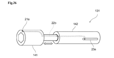
本発明を適用した例である六角穴付きのソケットレンチとして、図36に、ソケットレンチ131を、図37にソケットレンチ132を、それぞれ示す。ソケットレンチ131および132は、工具に対応する。 As an example of applying the present invention, a socket wrench 131 with a hexagonal hole is shown in FIG. 36, and a socket wrench 132 is shown in FIG. 37, respectively. Socket wrenches 131 and 132 correspond to tools.

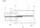
図36のソケットレンチ131は、その先端部141が、把持部142から取り外しが可能なように、先端部141の一部が把持部142の内部に嵌め込まれ、着脱可能な構成を有している。ソケットレンチ131の先端部141の端部には、ICタグ検出部21のうちのいずれか(図36においては、ICタグ検出部21a)が設けられている。把持部142にはリーダ/ライタ通信部23(図36においては、リーダ/ライタ通信部23a)が設けられている。タグ情報伝送部22(図36においては、タグ情報伝送部22b)は、先端部141および把持部142にかけて設けられ、その一部が切り離し可能なようになされている。 The socket wrench 131 of FIG. 36 has a structure in which a part of the tip portion 141 is fitted inside the grip portion 142 and is detachable so that the tip portion 141 can be removed from the grip portion 142. .. One of the IC tag detection units 21 (IC tag detection unit 21a in FIG. 36) is provided at the end of the tip portion 141 of the socket wrench 131. The grip portion 142 is provided with a reader / writer communication unit 23 (reader / writer communication unit 23a in FIG. 36). The tag information transmission unit 22 (tag information transmission unit 22b in FIG. 36) is provided over the tip portion 141 and the grip portion 142 so that a part thereof can be separated.

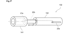
また、図37のソケットレンチ132おいても、その先端部141が、把持部142から取り外しが可能なように、先端部141の一部が把持部142の内部に嵌め込まれ、着脱可能な構成を有している。ソケットレンチ132においては、ボルト2をソケットレンチ132に挿入した状態で、ボルト2の頭部中央に設けられたICタグ3を検出することが可能なように、先端部141内のボルト2の挿入穴の対応する位置に、ICタグ検出部21eが設けられている。 Further, also in the socket wrench 132 of FIG. 37, a part of the tip portion 141 is fitted inside the grip portion 142 so that the tip portion 141 can be removed from the grip portion 142, so that the socket wrench 132 can be attached and detached. Have. In the socket wrench 132, the bolt 2 in the tip portion 141 is inserted so that the IC tag 3 provided in the center of the head of the bolt 2 can be detected with the bolt 2 inserted in the socket wrench 132. An IC tag detection unit 21e is provided at a corresponding position of the hole.

図38は、先端部141と把持部142との接続部分の拡大図である。図38を参照して、先端部141と把持部142との接続部分のタグ情報伝送部22の構造について説明する。 FIG. 38 is an enlarged view of a connecting portion between the tip portion 141 and the grip portion 142. With reference to FIG. 38, the structure of the tag information transmission unit 22 of the connection portion between the tip portion 141 and the grip portion 142 will be described.

先端部141側のタグ情報伝送部22bをタグ情報伝送部22b−1とし、把持部142側のタグ情報伝送部22bをタグ情報伝送部22b−2とする。タグ情報伝送部22b−1は、先端部141の内部に埋め込まれ、外部導体82は先端部141の金属部分と電気的に接続されている。また、先端部141側の把持部142との接続部分に対応するタグ情報伝送部22b−1の端部は、絶縁被覆81が取り除かれ、芯線41のみが露出した十分に小さい空洞となっている。また、タグ情報伝送部22b−2は、把持部142に埋め込まれ、外部導体82は把持部142の金属部分と電気的に接続されている。また、把持部142側の先端部141との接続部分に対応する空洞には、タグ情報伝送部22b−2端部が、絶縁被覆81が取り除かれ、芯線41のみが露出した状態となっている。タグ情報伝送部22b−2の芯線41の露出位置は、先端部141と把持部142とが接続された場合に、タグ情報伝送部22b−1端部の芯線41のみが露出した十分に小さい空洞内に挿入されるようになっている。 The tag information transmission unit 22b on the tip portion 141 side is referred to as a tag information transmission unit 22b-1, and the tag information transmission unit 22b on the grip portion 142 side is referred to as a tag information transmission unit 22b-2. The tag information transmission unit 22b-1 is embedded inside the tip portion 141, and the outer conductor 82 is electrically connected to the metal portion of the tip portion 141. Further, the end portion of the tag information transmission portion 22b-1 corresponding to the connection portion with the grip portion 142 on the tip portion 141 side is a sufficiently small cavity in which the insulating coating 81 is removed and only the core wire 41 is exposed. .. Further, the tag information transmission unit 22b-2 is embedded in the grip portion 142, and the outer conductor 82 is electrically connected to the metal portion of the grip portion 142. Further, in the cavity corresponding to the connection portion with the tip portion 141 on the grip portion 142 side, the insulating coating 81 is removed from the tag information transmission portion 22b-2 end portion, and only the core wire 41 is exposed. .. The exposed position of the core wire 41 of the tag information transmission unit 22b-2 is a sufficiently small cavity in which only the core wire 41 at the end of the tag information transmission unit 22b-1 is exposed when the tip portion 141 and the grip portion 142 are connected. It is designed to be inserted inside.

すなわち、先端部141と把持部142とが接続された場合、タグ情報伝送部22b−1端部の芯線41と、タグ情報伝送部22b−2端部の芯線41とは、接触、または静電誘導結合可能な距離に近接する。したがって、ICタグ検出部21とリーダ/ライタ通信部23とは、タグ情報伝送部22bにより電気的にも電磁気的にも接続された状態となる。 That is, when the tip portion 141 and the grip portion 142 are connected, the core wire 41 at the end of the tag information transmission unit 22b-1 and the core wire 41 at the end of the tag information transmission unit 22b-2 are in contact with each other or electrostatically charged. Close to the inductively coupled distance. Therefore, the IC tag detection unit 21 and the reader / writer communication unit 23 are in a state of being electrically and electromagnetically connected by the tag information transmission unit 22b.

なお、先端部141と把持部142とが接続された状態において、タグ情報伝送部22b−1端部の芯線41と、タグ情報伝送部22b−2端部の芯線41とが必ず静電誘電結合可能な距離となる場合、絶縁被覆81は取り除かれていなくてもよい。 In the state where the tip portion 141 and the grip portion 142 are connected, the core wire 41 at the end of the tag information transmission unit 22b-1 and the core wire 41 at the end of the tag information transmission unit 22b-2 are always electrostatically coupled. The insulation coating 81 may not be removed if the distance is possible.

ここでは、先端部141と把持部142との2つに分割可能なソケットレンチ131を例に挙げて説明したが、2つ以上の複数に分割可能な工具においても、上述した技術を適用可能であることは言うまでもない。 Here, the socket wrench 131 that can be divided into two, the tip portion 141 and the grip portion 142, has been described as an example, but the above-mentioned technique can also be applied to a tool that can be divided into two or more. Needless to say, there is.

以上説明したモンキーレンチ1、メガネレンチ125、ソケットレンチ131、または、ソケットレンチ132を用いた場合、ICタグ3の読み取り時に、モンキーレンチ1、メガネレンチ125、ソケットレンチ131、または、ソケットレンチ132から、リーダ/ライタ端末4へ、道具を持ち替える必要がない。したがって、作業に必要な時間を大幅に増やすことなく、作業者が手に持って作業するための工具を利用してICタグを読み取ることができるので、ボルト2等を適切に管理したり、装置の正しい位置に装着または取り外す場合のヒューマンエラーを防止することができる。さらに、モンキーレンチ1、メガネレンチ125、ソケットレンチ131、または、ソケットレンチ132を用いた場合、これらの内部には、リーダ/ライタ端末4の内部にあるような電源や電子回路が一切無いため、これらに起因する故障原因がなく、従来の工具と同等な取り扱いを可能とすることができる。 When the monkey wrench 1, the box wrench 125, the socket wrench 131, or the socket wrench 132 described above is used, the monkey wrench 1, the box wrench 125, the socket wrench 131, or the socket wrench 132 is used when reading the IC tag 3. , There is no need to switch tools to the reader / writer terminal 4. Therefore, the IC tag can be read by using a tool for the operator to hold and work without significantly increasing the time required for the work, so that the bolt 2 and the like can be properly managed and the device can be used. It is possible to prevent human error when mounting or removing the device in the correct position. Further, when a monkey wrench 1, a box wrench 125, a socket wrench 131, or a socket wrench 132 is used, there is no power supply or electronic circuit inside these, as in the reader / writer terminal 4. There is no cause of failure due to these, and it is possible to handle the same as a conventional tool.

上述した技術は、モンキーレンチ、メガネレンチ、ソケットレンチ以外にも、例えば、トルクレンチ、ドライバー、ボックスドライバー、ペンチ、ニッパー、ワイヤーストリッパー、その他の、少なくとも一部に金属を有する工具に適用することができる。これにより、多種多様な工具のうちの適切なものを用いて、ネジ・ボルト等を、装置の正しい位置に装着または取り外す工程を適切に管理することができる。 In addition to monkey wrenches, box wrenches, and socket wrenches, the techniques described above can be applied to, for example, torque wrenches, screwdrivers, box drivers, pliers, nippers, wire strippers, and other tools that have at least a portion of metal. it can. This makes it possible to properly manage the process of mounting or removing screws, bolts, etc. at the correct position of the device by using an appropriate tool among a wide variety of tools.

また、本発明の実施の形態は、上述した実施の形態に限定されるものではなく、本発明の要旨を逸脱しない範囲において種々の変更が可能である。 Further, the embodiment of the present invention is not limited to the above-described embodiment, and various modifications can be made without departing from the gist of the present invention.

1…モンキーレンチ(工具に対応する)、 2…ボルト、 3、3a、3b…ICタグ、 4…リーダ/ライタ端末、 12…上アゴ(金属に対応する)、 13…把持部(金属に対応する)、 21、21a〜f…ICタグ検出部、 22、22a〜c…タグ情報伝送部、 23、23a〜g…リーダ/ライタ通信部、 32…ICチップ、 33…コイルアンテナ、 35…アンテナ、 41…芯線、 42…接続点、 43…充填材、 61…目印、 65…溝、 70…絶縁物、 81…絶縁被覆(絶縁物に対応する)、 101…接続点、 111…充填材、 112…グリップ、 115…充填材、 121…紐(紐状部に対応する)、 125 メガネレンチ(工具に対応する) 131,132…ソケットレンチ(工具に対応する) 1 ... Monkey wrench (corresponding to tools), 2 ... Bolt, 3, 3a, 3b ... IC tag, 4 ... Reader / writer terminal, 12 ... Upper jaw (corresponding to metal), 13 ... Gripping part (corresponding to metal) , 21, 21a to f ... IC tag detection unit, 22, 22a to c ... tag information transmission unit, 23, 23a to g ... reader / writer communication unit, 32 ... IC chip, 33 ... coil antenna, 35 ... antenna , 41 ... Core wire, 42 ... Connection point, 43 ... Filler, 61 ... Mark, 65 ... Groove, 70 ... Insulation, 81 ... Insulation coating (corresponding to insulation), 101 ... Connection point, 111 ... Filler, 112 ... Grip, 115 ... Filling material, 121 ... String (corresponding to string-shaped part), 125 Adjustable wrench (corresponding to tool) 131, 132 ... Socket wrench (corresponding to tool)

Claims (22)

少なくとも一部が金属により構成され、作業者が把持することにより利用される工具において、
ICタグを検出するICタグ検出部と、
リーダ/ライタ端末と通信するリーダ/ライタ通信部と、
前記ICタグ検出部と前記リーダ/ライタ通信部とを接続するタグ情報伝送部とを備え、
前記タグ情報伝送部は、前記ICタグから読みこまれた、または、前記ICタグに書き込まれる情報を伝送するための芯線を含み、
前記ICタグ検出部は、前記金属の一部が切り欠かれることにより構成される内部空間を含み、
前記内部空間には、前記芯線の一部が露出し、当該芯線の前記内部空間における露出部分は直線状に形成されている、または前記内部空間を平面視したときに前記露出部分同士に重なり部分が形成されない状態の曲線状に前記露出部分が形成されていて、
前記芯線の端部は、前記内部空間を構成する前記金属に電気的に接続されている
ことを特徴とする工具。
In tools that are at least partially made of metal and are used by the operator to grip
IC tag detector that detects IC tags and
A reader / writer communication unit that communicates with a reader / writer terminal,
A tag information transmission unit for connecting the IC tag detection unit and the reader / writer communication unit is provided.
The tag information transmission unit includes a core wire for transmitting information read from the IC tag or written to the IC tag.
The IC tag detection unit includes an internal space formed by cutting out a part of the metal.
A part of the core wire is exposed in the internal space, and the exposed portion of the core wire in the internal space is formed in a straight line, or a portion overlapping the exposed portions when the internal space is viewed in a plan view. The exposed portion is formed in a curved shape in a state where
A tool characterized in that the end portion of the core wire is electrically connected to the metal constituting the internal space.
請求項1に記載の工具において、
前記ICタグ検出部の前記芯線の少なくとも一部は、前記内部空間の中心部からオフセットされた位置に露出される
ことを特徴とする工具。
In the tool according to claim 1,
A tool characterized in that at least a part of the core wire of the IC tag detection unit is exposed at a position offset from the central portion of the internal space.
請求項1または2に記載の工具において、
前記ICタグ検出部の前記内部空間は、前記工具の端部を、側面を含んで上面と下面を貫通するように切り欠くことによって構成される
ことを特徴とする工具。
In the tool according to claim 1 or 2.
A tool characterized in that the internal space of the IC tag detection unit is formed by cutting out an end portion of the tool so as to penetrate the upper surface and the lower surface including the side surface.
請求項1または2に記載の工具において、
前記ICタグ検出部の前記内部空間は、前記工具の端部であって、前記ICタグの検出面を、当該工具の下面と側面の間の角部分を含み、かつ貫通しない形状で切り欠くことによって構成される
ことを特徴とする工具。
In the tool according to claim 1 or 2.
The internal space of the IC tag detection unit is an end portion of the tool, and the detection surface of the IC tag is cut out in a shape that includes a corner portion between the lower surface and the side surface of the tool and does not penetrate. A tool characterized by being composed of.
請求項1または2に記載の工具において、
前記ICタグ検出部の前記内部空間は、前記工具の端部であって、前記ICタグの検出面を、当該工具の下面と側面の間の角部分を含み、かつ貫通しない形状で、角部分の稜線の延伸方向に対して斜めとなる方向に切り欠くことによって構成される
ことを特徴とする工具。
In the tool according to claim 1 or 2.
The internal space of the IC tag detection unit is an end portion of the tool, and has a shape that includes a corner portion between the lower surface and the side surface of the tool and does not penetrate the detection surface of the IC tag. A tool characterized in that it is constructed by cutting out in a direction diagonal to the extending direction of the ridgeline of.
請求項1または2に記載の工具において、
前記ICタグ検出部の前記内部空間は、前記ICタグの検出面から、当該検出面とは反対となる面へ貫通するように切り欠くことによって構成される
ことを特徴とする工具。
In the tool according to claim 1 or 2.
A tool characterized in that the internal space of the IC tag detection unit is formed by cutting out from the detection surface of the IC tag so as to penetrate to a surface opposite to the detection surface.
請求項1または2に記載の工具において、
前記ICタグ検出部の前記内部空間は、前記ICタグの検出面の一部をくり貫くことによって構成される
ことを特徴とする工具。
In the tool according to claim 1 or 2.
A tool characterized in that the internal space of the IC tag detection unit is formed by hollowing out a part of the detection surface of the IC tag.
請求項4、5、または7のいずれか1項に記載の工具において、
前記ICタグの検出面と反対となる面上であって、前記ICタグ検出部の前記内部空間に対応し、かつ、前記芯線とは異なる位置に設けられる目印をさらに含む
ことを特徴とする工具。
In tool according to any one of claims 4, 5 or 7,
A tool that is on a surface opposite to the detection surface of the IC tag, corresponds to the internal space of the IC tag detection unit, and further includes a mark provided at a position different from the core wire. ..
請求項1〜8のいずれか1項に記載の工具において、
前記タグ情報伝送部は、前記工具の外周面に設けられた溝内に配置され、
前記芯線は、絶縁物により、前記工具の金属部分から絶縁されている
ことを特徴とする工具。
In tool according to any one of claims 1 to 8,
The tag information transmission unit is arranged in a groove provided on the outer peripheral surface of the tool.
A tool characterized in that the core wire is insulated from a metal portion of the tool by an insulating material.
請求項1〜9のいずれか1項に記載の工具において、
前記工具は、2つ以上に分割可能であり、
前記タグ情報伝送部は、前記工具の分割とともに、2つ以上に分割され、その接続点において静電誘導結合される
ことを特徴とする工具。
In tool according to any one of claims 1-9,
The tool can be divided into two or more
A tool characterized in that the tag information transmission unit is divided into two or more at the same time as the tool is divided, and electrostatically inducedly coupled at the connection point thereof.
請求項1〜10のいずれか1項に記載の工具において、
前記リーダ/ライタ通信部は、前記工具の金属部分の一部に形成されたスリットと、前記スリットの端部に露出した前記芯線の一部により構成されたスリットアンテナであり、
前記スリットに露出した前記芯線は前記スリット内の前記金属部分に電気的に接続されている
ことを特徴とする工具。
In tool according to any one of claims 1 to 10,
The reader / writer communication unit is a slit antenna composed of a slit formed in a part of a metal portion of the tool and a part of the core wire exposed at the end of the slit.
A tool characterized in that the core wire exposed in the slit is electrically connected to the metal portion in the slit.
請求項11に記載の工具であって、
前記リーダ/ライタ通信部の前記スリットの内周を一巡する長さは、前記リーダ/ライタ端末との通信波長と同程度である
ことを特徴とする工具。
The tool according to claim 11.
A tool characterized in that the length of the reader / writer communication unit that goes around the inner circumference of the slit is about the same as the communication wavelength with the reader / writer terminal.
請求項11に記載の工具であって、
前記リーダ/ライタ通信部の前記スリットには、媒質定数が1より大きい充填材が充填されている
ことを特徴とする工具。
The tool according to claim 11.
A tool characterized in that the slit of the reader / writer communication unit is filled with a filler having a medium constant greater than 1.
請求項11〜13のいずれか1項に記載の工具であって、
前記リーダ/ライタ通信部の前記スリットの中央部を少なくとも覆い、電気伝導性を有さず、磁界を透過する材質により構成されたグリップをさらに備える
ことを特徴とする工具。
The tool according to any one of claims 11 to 13.
A tool characterized in that it covers at least the central portion of the slit of the reader / writer communication unit, and further includes a grip made of a material that does not have electrical conductivity and transmits a magnetic field.
請求項1〜10のいずれか1項に記載の工具において、
電気伝導性を有せず、磁界を透過する素材により構成された紐状部を更に備え、
前記リーダ/ライタ通信部は、前記紐状部の内部に設けられ、前記芯線に接続されたダイポールアンテナである
ことを特徴とする工具。
In tool according to any one of claims 1 to 10,
It also has a string-like part made of a material that does not have electrical conductivity and transmits a magnetic field.
The reader / writer communication unit is a tool provided inside the string-shaped portion and is a dipole antenna connected to the core wire.
請求項1〜10のいずれか1項に記載の工具において、
電気伝導性を有せず、磁界を透過する素材により構成された紐状部を更に備え、
前記リーダ/ライタ通信部は、前記紐状部の内部に設けられ、前記芯線に接続されたモノポールアンテナである
ことを特徴とする工具。
In tool according to any one of claims 1 to 10,
It also has a string-like part made of a material that does not have electrical conductivity and transmits a magnetic field.
The reader / writer communication unit is a tool provided inside the string-shaped portion and is a monopole antenna connected to the core wire.
少なくとも一部が金属により構成され、作業者が把持することにより利用される工具において、
ICタグを検出するICタグ検出部と、
リーダ/ライタ端末と通信するリーダ/ライタ通信部と、
前記ICタグ検出部と前記リーダ/ライタ通信部とを接続するタグ情報伝送部とを備え、
前記タグ情報伝送部は、前記ICタグから読みこまれた、または、前記ICタグに書き込まれる情報を伝送するための芯線を含み、
前記リーダ/ライタ通信部は、前記工具の金属部分の一部に形成されたスリットと、前記スリットの端部に露出した前記芯線の一部により構成されたスリットアンテナであり、
前記スリットに露出した前記芯線は前記スリット内の前記金属部分に電気的に接続されている
ことを特徴とする工具。
In tools that are at least partially made of metal and are used by the operator to grip
IC tag detector that detects IC tags and
A reader / writer communication unit that communicates with a reader / writer terminal,
A tag information transmission unit for connecting the IC tag detection unit and the reader / writer communication unit is provided.
The tag information transmission unit includes a core wire for transmitting information read from the IC tag or written to the IC tag.
The reader / writer communication unit is a slit antenna composed of a slit formed in a part of a metal portion of the tool and a part of the core wire exposed at the end of the slit.
A tool characterized in that the core wire exposed in the slit is electrically connected to the metal portion in the slit.
請求項17に記載の工具であって、
前記リーダ/ライタ通信部の前記スリットの内周を一巡する長さは、前記リーダ/ライタ端末との通信波長と同程度である
ことを特徴とする工具。
The tool according to claim 17.
A tool characterized in that the length of the reader / writer communication unit that goes around the inner circumference of the slit is about the same as the communication wavelength with the reader / writer terminal.
請求項17に記載の工具であって、
前記リーダ/ライタ通信部の前記スリットには、媒質定数が1より大きい値の充填材が充填されている
ことを特徴とする工具。
The tool according to claim 17.
A tool characterized in that the slit of the reader / writer communication unit is filled with a filler having a medium constant of more than 1.
請求項17〜19のいずれか1項に記載の工具であって、
前記リーダ/ライタ通信部の前記スリットの中央部を少なくとも覆い、電気伝導性を有さず、磁界を透過する材質により構成されたグリップをさらに備える
ことを特徴とする工具。
The tool according to any one of claims 17 to 19.
A tool characterized in that it covers at least the central portion of the slit of the reader / writer communication unit, and further includes a grip made of a material that does not have electrical conductivity and transmits a magnetic field.
少なくとも一部が金属により構成され、作業者が把持することにより利用される工具において、
ICタグを検出するICタグ検出部と、
リーダ/ライタ端末と通信するリーダ/ライタ通信部と、
前記ICタグ検出部と前記リーダ/ライタ通信部とを接続するタグ情報伝送部と、
電気伝導性を有せず、磁界を透過する素材により構成された紐状部と
を備え、
前記リーダ/ライタ通信部は、前記紐状部の内部に設けられ、
前記リーダ/ライタ通信部は、前記ICタグから読みこまれた、または、前記ICタグに書き込まれる情報を伝送する芯線の一部を含み、その芯線の一部は前記タグ情報伝送部に含まれる芯線の他の部分と連続していて、
さらに前記リーダ/ライタ通信部は、前記芯線の一部に連続すると共に前記芯線の一部とは反対側に延伸する伝導体を含み、該伝導体は前記芯線の一部と共にダイポールアンテナを構成する
ことを特徴とする工具。
In tools that are at least partially made of metal and are used by the operator to grip
IC tag detector that detects IC tags and
A reader / writer communication unit that communicates with a reader / writer terminal,
A tag information transmission unit that connects the IC tag detection unit and the reader / writer communication unit,
It has a string-like part made of a material that does not have electrical conductivity and transmits a magnetic field.
The reader / writer communication unit is provided inside the string-shaped portion.
The reader / writer communication unit includes a part of a core wire for transmitting information read from the IC tag or written in the IC tag, and a part of the core wire is included in the tag information transmission unit. It is continuous with the other parts of the core wire
Further, the reader / writer communication unit includes a conductor that is continuous with a part of the core wire and extends to the side opposite to the part of the core wire, and the conductor constitutes a dipole antenna together with the part of the core wire. A tool characterized by that.
少なくとも一部が金属により構成され、作業者が把持することにより利用される工具において、
ICタグを検出するICタグ検出部と、
リーダ/ライタ端末と通信するリーダ/ライタ通信部と、
前記ICタグ検出部と前記リーダ/ライタ通信部とを接続するタグ情報伝送部と、
電気伝導性を有せず、磁界を透過する素材により構成された紐状部と
を備え、
前記リーダ/ライタ通信部は、前記紐状部の内部に設けられ、
前記リーダ/ライタ通信部は、前記ICタグから読みこまれた、または、前記ICタグに書き込まれる情報を伝送する芯線の一部を含み、その芯線の一部は前記タグ情報伝送部に含まれる芯線の他の部分と連続していて、
前記芯線の一部はモノポールアンテナを構成する
ことを特徴とする工具。
In tools that are at least partially made of metal and are used by the operator to grip
IC tag detector that detects IC tags and
A reader / writer communication unit that communicates with a reader / writer terminal,
A tag information transmission unit that connects the IC tag detection unit and the reader / writer communication unit,
It has a string-like part made of a material that does not have electrical conductivity and transmits a magnetic field.
The reader / writer communication unit is provided inside the string-shaped portion.
The reader / writer communication unit includes a part of a core wire for transmitting information read from the IC tag or written in the IC tag, and a part of the core wire is included in the tag information transmission unit. It is continuous with the other parts of the core wire
A tool characterized in that a part of the core wire constitutes a monopole antenna.
JP2017017142A 2017-02-01 2017-02-01 tool Active JP6861411B2 (en)

Priority Applications (1)

Application Number Priority Date Filing Date Title
JP2017017142A JP6861411B2 (en) 2017-02-01 2017-02-01 tool

Applications Claiming Priority (1)

Application Number Priority Date Filing Date Title
JP2017017142A JP6861411B2 (en) 2017-02-01 2017-02-01 tool

Publications (2)

Publication Number Publication Date
JP2018124840A JP2018124840A (en) 2018-08-09
JP6861411B2 true JP6861411B2 (en) 2021-04-21

Family

ID=63110358

Family Applications (1)

Application Number Title Priority Date Filing Date
JP2017017142A Active JP6861411B2 (en) 2017-02-01 2017-02-01 tool

Country Status (1)

Country Link
JP (1) JP6861411B2 (en)

Families Citing this family (1)

* Cited by examiner, † Cited by third party
Publication number Priority date Publication date Assignee Title
JP2021194765A (en) * 2020-06-11 2021-12-27 東京エレクトロン株式会社 Fastening control device and fastening control method

Family Cites Families (5)

* Cited by examiner, † Cited by third party
Publication number Priority date Publication date Assignee Title
JP2916474B1 (en) * 1998-06-03 1999-07-05 八木アンテナ株式会社 Label writing head
JP2008123231A (en) * 2006-11-10 2008-05-29 Hitachi Ltd RFID tag reading system and RFID tag reading method
JP6018462B2 (en) * 2012-09-14 2016-11-02 株式会社リコー Antenna and wireless communication device
JP6225004B2 (en) * 2013-12-03 2017-11-01 株式会社Iro Socket fitting for valve opening / closing, valve, valve switch, valve information reader
JP5909572B1 (en) * 2015-03-17 2016-04-26 株式会社Iro Detection instrument

Also Published As

Publication number Publication date
JP2018124840A (en) 2018-08-09

Similar Documents

Publication Publication Date Title
EP3051297B1 (en) Electrical conductor testing device
US8912888B2 (en) Information storage medium, object of management and management system
CN110165363B (en) Omnidirectional Antenna for Cylindrical Body
US9600759B2 (en) RFID identification of metal interchangeable parts for machine tools
CA2499832A1 (en) Ruggedized multi-layer printed circuit board based downhole antenna
KR20200108448A (en) Metal fastener with embedded RFID tag and manufacturing method
TW202025578A (en) Presswerkzeug-netzwerk und verfahren zum verpressen eines werkstuecks
US20130140371A1 (en) Non-contact ic label and nameplate
JP2016093873A (en) Torque wrench and automatic recognition system
JP6861411B2 (en) tool
US20180323499A1 (en) An antenna device for hf and lf operation
JP5261994B2 (en) Identification tag and cable identification system
CN105470648B (en) Frequency characteristic alignment jig, antenna measurement apparatus and method and loop antenna
JP6650641B2 (en) Director
US11616285B2 (en) Measuring device with near field antenna
JP5909572B1 (en) Detection instrument
JP2016095730A (en) IC tag mounting structure
TWI556505B (en) Improve the communication chip and information memory media
JP7178451B1 (en) flexible antenna
JP4542472B2 (en) Cable tie with wireless IC tag
US20070052609A1 (en) Dual-band or single-band dipole antenna
JP6576541B2 (en) Detection device, rotary switch mechanism
JP6793399B2 (en) Torque measuring device
TW202419225A (en) tool
JP6857462B2 (en) Replacement socket adapter with rotary relay antenna, fixed relay antenna member, replacement socket adapter with bolt detection function with IC tag, and powered driver

Legal Events

Date Code Title Description
A621 Written request for application examination

Free format text: JAPANESE INTERMEDIATE CODE: A621

Effective date: 20200130

A977 Report on retrieval

Free format text: JAPANESE INTERMEDIATE CODE: A971007

Effective date: 20201130

A131 Notification of reasons for refusal

Free format text: JAPANESE INTERMEDIATE CODE: A131

Effective date: 20201215

A521 Request for written amendment filed

Free format text: JAPANESE INTERMEDIATE CODE: A523

Effective date: 20210215

TRDD Decision of grant or rejection written
A01 Written decision to grant a patent or to grant a registration (utility model)

Free format text: JAPANESE INTERMEDIATE CODE: A01

Effective date: 20210302

A61 First payment of annual fees (during grant procedure)

Free format text: JAPANESE INTERMEDIATE CODE: A61

Effective date: 20210322

R150 Certificate of patent or registration of utility model

Ref document number: 6861411

Country of ref document: JP

Free format text: JAPANESE INTERMEDIATE CODE: R150

R250 Receipt of annual fees

Free format text: JAPANESE INTERMEDIATE CODE: R250

S111 Request for change of ownership or part of ownership

Free format text: JAPANESE INTERMEDIATE CODE: R313117

R250 Receipt of annual fees

Free format text: JAPANESE INTERMEDIATE CODE: R250

R350 Written notification of registration of transfer

Free format text: JAPANESE INTERMEDIATE CODE: R350