JP6860809B2 - Stamp unit - Google Patents
Stamp unit Download PDFInfo
- Publication number
- JP6860809B2 JP6860809B2 JP2016192369A JP2016192369A JP6860809B2 JP 6860809 B2 JP6860809 B2 JP 6860809B2 JP 2016192369 A JP2016192369 A JP 2016192369A JP 2016192369 A JP2016192369 A JP 2016192369A JP 6860809 B2 JP6860809 B2 JP 6860809B2
- Authority
- JP
- Japan
- Prior art keywords
- ink storage
- frame
- stamp
- printing
- elastic
- Prior art date
- Legal status (The legal status is an assumption and is not a legal conclusion. Google has not performed a legal analysis and makes no representation as to the accuracy of the status listed.)
- Active
Links
- 238000003860 storage Methods 0.000 claims description 42
- 239000011148 porous material Substances 0.000 description 7
- 239000012466 permeate Substances 0.000 description 5
- 239000011347 resin Substances 0.000 description 5
- 229920005989 resin Polymers 0.000 description 5
- 210000000078 claw Anatomy 0.000 description 4
- 238000000034 method Methods 0.000 description 4
- 230000035515 penetration Effects 0.000 description 4
- 238000002844 melting Methods 0.000 description 3
- 230000008018 melting Effects 0.000 description 3
- 230000000149 penetrating effect Effects 0.000 description 3
- -1 polyethylene Polymers 0.000 description 3
- 239000002994 raw material Substances 0.000 description 3
- VTYYLEPIZMXCLO-UHFFFAOYSA-L Calcium carbonate Chemical compound [Ca+2].[O-]C([O-])=O VTYYLEPIZMXCLO-UHFFFAOYSA-L 0.000 description 2
- 239000004698 Polyethylene Substances 0.000 description 2
- 239000004743 Polypropylene Substances 0.000 description 2
- PPBRXRYQALVLMV-UHFFFAOYSA-N Styrene Chemical compound C=CC1=CC=CC=C1 PPBRXRYQALVLMV-UHFFFAOYSA-N 0.000 description 2
- 230000007547 defect Effects 0.000 description 2
- 238000009826 distribution Methods 0.000 description 2
- 239000000945 filler Substances 0.000 description 2
- 238000010438 heat treatment Methods 0.000 description 2
- 238000009434 installation Methods 0.000 description 2
- VWDWKYIASSYTQR-UHFFFAOYSA-N sodium nitrate Chemical compound [Na+].[O-][N+]([O-])=O VWDWKYIASSYTQR-UHFFFAOYSA-N 0.000 description 2
- 239000000126 substance Substances 0.000 description 2
- XLYOFNOQVPJJNP-UHFFFAOYSA-N water Substances O XLYOFNOQVPJJNP-UHFFFAOYSA-N 0.000 description 2
- JOYRKODLDBILNP-UHFFFAOYSA-N Ethyl urethane Chemical compound CCOC(N)=O JOYRKODLDBILNP-UHFFFAOYSA-N 0.000 description 1
- 229920000459 Nitrile rubber Polymers 0.000 description 1
- 229920002472 Starch Polymers 0.000 description 1
- BZHJMEDXRYGGRV-UHFFFAOYSA-N Vinyl chloride Chemical compound ClC=C BZHJMEDXRYGGRV-UHFFFAOYSA-N 0.000 description 1
- 239000002253 acid Substances 0.000 description 1
- 239000000853 adhesive Substances 0.000 description 1
- 230000001070 adhesive effect Effects 0.000 description 1
- 150000001336 alkenes Chemical class 0.000 description 1
- 229910000019 calcium carbonate Inorganic materials 0.000 description 1
- 235000010216 calcium carbonate Nutrition 0.000 description 1
- 239000000975 dye Substances 0.000 description 1
- 239000000835 fiber Substances 0.000 description 1
- 239000006260 foam Substances 0.000 description 1
- 230000004927 fusion Effects 0.000 description 1
- 238000004519 manufacturing process Methods 0.000 description 1
- 239000000463 material Substances 0.000 description 1
- 239000004745 nonwoven fabric Substances 0.000 description 1
- JRZJOMJEPLMPRA-UHFFFAOYSA-N olefin Natural products CCCCCCCC=C JRZJOMJEPLMPRA-UHFFFAOYSA-N 0.000 description 1
- 239000002245 particle Substances 0.000 description 1
- 239000000049 pigment Substances 0.000 description 1
- 229920002647 polyamide Polymers 0.000 description 1
- 229920000728 polyester Polymers 0.000 description 1
- 229920000573 polyethylene Polymers 0.000 description 1
- 229920000139 polyethylene terephthalate Polymers 0.000 description 1
- 239000005020 polyethylene terephthalate Substances 0.000 description 1
- 229920000098 polyolefin Polymers 0.000 description 1
- 229920001155 polypropylene Polymers 0.000 description 1
- 239000004814 polyurethane Substances 0.000 description 1
- 229920003225 polyurethane elastomer Polymers 0.000 description 1
- 239000000047 product Substances 0.000 description 1
- 150000003839 salts Chemical class 0.000 description 1
- 238000004904 shortening Methods 0.000 description 1
- 235000002639 sodium chloride Nutrition 0.000 description 1
- 235000010344 sodium nitrate Nutrition 0.000 description 1
- 239000004317 sodium nitrate Substances 0.000 description 1
- 239000008107 starch Substances 0.000 description 1
- 235000019698 starch Nutrition 0.000 description 1
- 229920002725 thermoplastic elastomer Polymers 0.000 description 1
Images


Classifications
-
- B—PERFORMING OPERATIONS; TRANSPORTING
- B41—PRINTING; LINING MACHINES; TYPEWRITERS; STAMPS
- B41K—STAMPS; STAMPING OR NUMBERING APPARATUS OR DEVICES
- B41K1/00—Portable hand-operated devices without means for supporting or locating the articles to be stamped, i.e. hand stamps; Inking devices or other accessories therefor
- B41K1/36—Details
- B41K1/38—Inking devices; Stamping surfaces
- B41K1/40—Inking devices operated by stamping movement
-
- B—PERFORMING OPERATIONS; TRANSPORTING
- B41—PRINTING; LINING MACHINES; TYPEWRITERS; STAMPS
- B41K—STAMPS; STAMPING OR NUMBERING APPARATUS OR DEVICES
- B41K1/00—Portable hand-operated devices without means for supporting or locating the articles to be stamped, i.e. hand stamps; Inking devices or other accessories therefor
- B41K1/36—Details
- B41K1/38—Inking devices; Stamping surfaces
- B41K1/50—Stamping surfaces impregnated with ink, or made of material leaving a mark after stamping contact
-
- B—PERFORMING OPERATIONS; TRANSPORTING
- B41—PRINTING; LINING MACHINES; TYPEWRITERS; STAMPS
- B41D—APPARATUS FOR THE MECHANICAL REPRODUCTION OF PRINTING SURFACES FOR STEREOTYPE PRINTING; SHAPING ELASTIC OR DEFORMABLE MATERIAL TO FORM PRINTING SURFACES
- B41D7/00—Shaping elastic or deformable material, e.g. rubber, plastics material, to form printing surfaces
-
- B—PERFORMING OPERATIONS; TRANSPORTING
- B41—PRINTING; LINING MACHINES; TYPEWRITERS; STAMPS
- B41K—STAMPS; STAMPING OR NUMBERING APPARATUS OR DEVICES
- B41K1/00—Portable hand-operated devices without means for supporting or locating the articles to be stamped, i.e. hand stamps; Inking devices or other accessories therefor
- B41K1/02—Portable hand-operated devices without means for supporting or locating the articles to be stamped, i.e. hand stamps; Inking devices or other accessories therefor with one or more flat stamping surfaces having fixed images
- B41K1/04—Portable hand-operated devices without means for supporting or locating the articles to be stamped, i.e. hand stamps; Inking devices or other accessories therefor with one or more flat stamping surfaces having fixed images with multiple stamping surfaces; with stamping surfaces replaceable as a whole
-
- B—PERFORMING OPERATIONS; TRANSPORTING
- B41—PRINTING; LINING MACHINES; TYPEWRITERS; STAMPS
- B41K—STAMPS; STAMPING OR NUMBERING APPARATUS OR DEVICES
- B41K1/00—Portable hand-operated devices without means for supporting or locating the articles to be stamped, i.e. hand stamps; Inking devices or other accessories therefor
- B41K1/36—Details
- B41K1/38—Inking devices; Stamping surfaces
- B41K1/44—Inking devices; Stamping surfaces for offset, intaglio, or stencil stamping
-
- B—PERFORMING OPERATIONS; TRANSPORTING
- B41—PRINTING; LINING MACHINES; TYPEWRITERS; STAMPS
- B41K—STAMPS; STAMPING OR NUMBERING APPARATUS OR DEVICES
- B41K1/00—Portable hand-operated devices without means for supporting or locating the articles to be stamped, i.e. hand stamps; Inking devices or other accessories therefor
- B41K1/36—Details
- B41K1/38—Inking devices; Stamping surfaces
- B41K1/52—Ink reservoirs, e.g. integral with stamp handles
Description
本発明は、多孔質膜の印字体とインキ吸蔵体とを有する印体ユニット及びそれを備える印判に関する。 The present invention relates to a stamp unit having a printed body of a porous film and an ink storage body, and a stamp including the stamp unit.
近年、印判を販売する店頭などに設置したサーマル加工機を用いて、顧客がデザインした印面パターンをその場で加工し、これによりオリジナルの印判を手軽に受け取ることができるサービスが提供され評判を呼んでいる(例えば特許文献1参照)。 In recent years, a service that allows customers to easily receive original stamps by processing the stamp pattern designed by the customer on the spot using a thermal processing machine installed at a store that sells stamps has gained a reputation. (See, for example, Patent Document 1).
この種の印判は、印字体(ステンシル)が多孔質膜で形成される。印字体には、加工機のサーマルヘッドにより、インキ浸透率が大きい捺印部と、インキ浸透率が小さい非捺印部とが高精度に加工される。印字体の背面には、ケース体内のインキ吸蔵体が当接し、これにより印字体にインキが供給される。 In this type of stamp, the printed body (stencil) is formed of a porous film. On the printed matter, the thermal head of the processing machine processes the stamped portion having a high ink penetration rate and the non-stamped portion having a low ink penetration rate with high accuracy. The ink storage body inside the case comes into contact with the back surface of the printing body, whereby ink is supplied to the printing body.
ところで、未加工の印字体にインキが含浸した状態では、熱加工制御が困難であるとともに、加工時にサーマルヘッドやフィルム等の部材を汚損する等の不具合が生じるおそれがある。このような不具合を防ぐため、例えば特許文献2及び3には、印字体とインキ吸蔵体とが当接しない位置に保持され、印字体の枠に外力を加えこれらを嵌合させることで、印字体とインキ吸蔵体とを当接させるようにした印判及びその製造方法が開示されている。 By the way, when the unprocessed printed matter is impregnated with ink, it is difficult to control the thermal processing, and there is a possibility that problems such as stains on members such as a thermal head and a film during processing may occur. In order to prevent such a problem, for example, in Patent Documents 2 and 3, the printed body and the ink storage body are held at positions where they do not come into contact with each other, and an external force is applied to the frame of the printed body to fit them. A stamp in which a font and an ink storage body are brought into contact with each other and a method for manufacturing the stamp are disclosed.
しかし、特許文献2及び3に記載の印判は、印字体をケース体に嵌合する構成であるため、市場での流通時に不測の外力が加えられると、印字体とケース体とが嵌合し、その結果印字体へのインキの浸透が開始してしまう場合があった。 However, since the stamps described in Patent Documents 2 and 3 have a configuration in which the printed body is fitted to the case body, the printed body and the case body are fitted to each other when an unexpected external force is applied during distribution in the market. As a result, the ink may start to permeate the printed matter.
そこで、本発明は、枠体やケース体に不測の外力が加えられたとしても、印字体へのインキの浸透を防ぐことで、印面の熱加工制御性を十分確保することができる等の印体ユニット又はそれを備える印判を提供することを目的としている。 Therefore, according to the present invention, even if an unexpected external force is applied to the frame body or the case body, it is possible to sufficiently secure the thermal processing controllability of the stamp surface by preventing the ink from penetrating into the printed body. It is intended to provide a body unit or a stamp with it.
上述した課題を解決するため、本発明は、ケース体にインキ吸蔵体を収容し、枠体に張設した多孔質膜の印字体を前記インキ吸蔵体に対向して形成した印体ユニットであって、前記印字体と前記インキ吸蔵体とを離隔させる弾性体を備えたことを特徴とする。 In order to solve the above-mentioned problems, the present invention is a stamping unit in which an ink storage body is housed in a case body and a printed body of a porous film stretched on a frame body is formed so as to face the ink storage body. It is characterized by having an elastic body that separates the printing body and the ink storage body.
上記構成の印体ユニットにおいて、前記弾性体が、前記インキ吸蔵体と前記印字体とを常時離隔する方向に付勢する弾性反発体であること、更には、前記弾性体が、前記ケース体と前記枠体との間に介装した弧状の板バネであることが好ましい。 In the stamp unit having the above configuration, the elastic body is an elastic rebound body that urges the ink storage body and the printing body in a direction that constantly separates them, and further, the elastic body is the case body. It is preferable that the leaf spring has an arc shape interposed between the frame and the frame.
また、上記構成の印体ユニットにおいて、前記弾性体を圧縮させることで、前記インキ吸蔵体と前記印字体とが接触する位置に前記枠体が移動可能であることが好ましい。 Further, in the stamp unit having the above configuration, it is preferable that the frame body can be moved to a position where the ink storage body and the printing body come into contact with each other by compressing the elastic body.
また、上記構成の印体ユニットにおいて、前記ケース体にホルダを取り付けたときに、前記弾性体が圧縮し、前記印字体を前記インキ吸蔵体に接触させた状態で前記枠体を保持することが好ましい。 Further, in the stamp unit having the above configuration, when the holder is attached to the case body, the elastic body is compressed and the frame body is held in a state where the printed body is in contact with the ink storage body. preferable.
本発明によれば、ケース体にインキ吸蔵体を収容し、枠体に張設した多孔質膜の印字体を前記インキ吸蔵体に対向して形成した印体ユニットが、印字体とインキ吸蔵体とを離隔させる弾性体を備えるようにした。そのため、枠体やケース体に不測の外力が加えられたとしても、印字体とインキ吸蔵体とが接触せず、印字体へのインキの浸透を未然に防ぐことができる。また、ケース体と枠体だけではホルダと枠体とが最終嵌合した状態にならず、ケース体にホルダを取り付けた場合に弾性体が圧縮し、印字体をインキ吸蔵体に接触させた状態で枠体を保持することができるようにした。したがって、印字体にインキが浸透しない状態で印面の熱加工を確実に行うことができ、印面加工時の不具合を引き起こす要因を排除して、印面の熱加工制御性を十分確保することができる。 According to the present invention, a stamp unit in which an ink storage body is housed in a case body and a printed body of a porous film stretched on a frame body is formed so as to face the ink storage body is a printing body and an ink storage body. It is provided with an elastic body that separates the and. Therefore, even if an unexpected external force is applied to the frame body or the case body, the printed body and the ink storage body do not come into contact with each other, and the ink can be prevented from permeating into the printed body. Further, the case body and the frame body alone do not make the holder and the frame body finally fit, and when the holder is attached to the case body, the elastic body is compressed and the printed body is brought into contact with the ink storage body. The frame can be held with. Therefore, the thermal processing of the stamp surface can be reliably performed in a state where the ink does not penetrate into the printed body, and the factors that cause defects during the stamp surface processing can be eliminated, and the thermal processing controllability of the stamp surface can be sufficiently ensured.
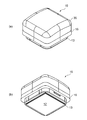
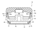
以下、多孔質印判を構成する印体ユニットの好適な実施形態を説明する。ここで、図1は、本発明の一実施形態による、ホルダ30と枠体13とが嵌合した最終嵌合状態の印体ユニット10の外観斜視図である。図2は、ホルダ30と枠体13とが嵌合した最終嵌合状態の印体ユニット10の断面図である。なお、図2は、ホルダ30がケース体16に嵌合した最終嵌合状態が図示されている。
Hereinafter, preferred embodiments of the stamp unit constituting the porous stamp will be described. Here, FIG. 1 is an external perspective view of the
本実施形態による印体ユニット10は、印判を販売する店頭などに設置される専用のサーマル加工機50(図8及び9参照)を用いて、例えば顧客が注文又はデザインした印面のデータに基づいて印面パターンを精度良く加工することができる、というものである。そのために、印体ユニット10は、多孔質膜で形成される印字体12と、印字体12の背面に接触してインキを浸透させて供給するインキ吸蔵体15とを備えている。後述する加工機50のサーマルヘッドを駆動制御することで、多孔質膜の印字体12には、インキの浸透率が大きい捺印部とインキの浸透率が小さい非捺印部とが加工され、これにより高精度の印面パターンが形成される。
The
印字体12である多硬質膜は、サーマルヘッドにより表面が加熱溶融し固化できる多孔質材であれば特に限定されない。この多孔質材の原材料として、例えばスチレン系、塩化ビニル系、オレフィン系、ポリエステル系、ポリアミド系、ウレタン系等の熱可塑性エラストマーを用いることができる。多孔性を得るためには、加熱加圧ニーダー、加熱ロール等により、デンプン、食塩、硝酸ナトリウム、炭酸カルシウム等の充填材と原材料樹脂とを混練し、シート状にして冷却後、水又は希酸水にて前記充填材を溶出する。この方法により作製される多孔質材の溶融温度は原材料樹脂と同じである。また、顔料、染料、無機質等の副成分を樹脂に添加することで、多孔質材の溶融温度の調整が可能である。本実施形態による多孔質材の溶融温度は70℃〜120℃である。
The multi-hard film as the
印字体12を構成する多硬質膜の気孔率及び気孔径は、混練される溶解物質の粒径やそれらの含有量により調整することができる。本実施形態による多硬質膜の気孔率は50%〜80%であり、気孔径は1μm〜20μmである。多硬質膜を2層構造にし、インキ吸蔵体15側の気孔率を50μm〜100μmとしてもよい。
The porosity and pore diameter of the multi-hard film constituting the printed
本実施形態による印体ユニット10は、上述の印字体12を設ける枠体13と、インキ吸蔵体15を収容するケース体16とを備えて構成される。
The
図3に枠体13の斜視図を示す。枠体13は、例えば樹脂により一体成型される部材である。図1(a)に図示したように、多孔質膜から形成される印字体12は、略四角形の枠体13の開口部13aを閉塞するように張設される。例えば、印字体12の外縁部が枠体13の開口端の前面に接着され、好ましくは融着されている。また、枠体13には、後述するホルダ30に係合する例えば4本の係合肢14が、印面とは反対側に延びて一体形成されている。
FIG. 3 shows a perspective view of the
図4にケース体16の斜視図を示す。ケース体16は、上述の枠体13と略同形で同寸法の外形を有するフランジ部16aを備える概ね厚板状の樹脂部材からなる。図2の断面図に示したように、インキ吸蔵体15は、フランジ部16aの内側の壁17で囲われる中央に面接着される。また、壁17とフランジ部16aとの境界付近に、上述した枠体13の係合肢14を通すための孔18が4か所に貫通形成されている。
FIG. 4 shows a perspective view of the
なお、インキ吸蔵体15の材質としては、例えば、ポリエチレン、ポリプロピレン、ポリエチレンテレフタレート、ポリウレタン、アクリルニトリルブタジエンゴム等の弾力性のある発泡体又は不織布を採用することができる。
As the material of the
インキ吸蔵体15においては、時間が経つと、例えばインキの粘性が高まる等の理由により、印字体12へのインキ浸透効率が落ちる傾向にある。そのため、インキ吸蔵体15を目付量の異なる2層で形成することが好ましい。例えば、ポリオレフィン系繊維(PP+PE)でインキ吸蔵体を形成した場合、ケース体16側の第一層の目付量を0.1〜0.15g/cm2とし、印字体12側の第二層の目付量を0.2〜0.3g/cm2とすることが好ましい。つまり、印字体12側の密度を高くすることにより、毛細管力の差によるインキの流れを作ることができ、これにより多孔質膜(印字体12)へのインキの浸透時間を安定的に短くすることができる。
In the
なお、インキ吸蔵体15が2層の場合、第一層と第二層を熱融着により接着することが好ましい。また、接着剤により2層を部分的に接着してもよい。また、これらを接着せず、各層の接合面に凹凸を設ける等の加工を施して、位置ずれを防止するようにしてもよい。
When the
印体ユニット10は、予めインキを含浸させたインキ吸蔵体15を収容するケース体16に、印字体12を有する枠体13を嵌合させた状態で市場に流通し顧客に提供される商品である。しかし、印体ユニット10が顧客に提供される前に、例えば何らかの不測の外力によりインキ吸蔵体15と印字体12とが接触すると、インキ吸蔵体15から印字体12へのインキの浸透が開始し、印面加工時に不具合を生じさせるおそれがある。そのため、本実施形態の印体ユニット10は、印字体12とインキ吸蔵体15との不測の接触を防ぎ、仮に接触したとしてもこれらを離隔させる方向に付勢力を常時作用させる反発弾性体を備えている。ここで、ホルダ30がケース体16と予め嵌合した状態であると、不測の外力が加えられた時にノッチ30aと爪部14aとが嵌合し、印字体12へインキの浸透が開始してしまう可能性があるため、ホルダ30とケース体16は別体であることが好ましい。
The
このような反発弾性体は、ケース体16と枠体13との間に介装される、例えば図4に示す円弧状の板バネ20とすることができる。板バネ20を圧縮させることで、インキ吸蔵体15と印字体12とが接触する位置に枠体13を移動させることができる。
Such a repulsive elastic body can be, for example, an arc-shaped
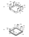
本実施形態による印体ユニット10は、ホルダ30を枠体13に最終嵌合させることで組み立てられる構造を有している。ここで、図5(a)及び図6(a)に、ケース体16と枠体13とが嵌合した状態の斜視図と側面図を示す(流通時)。図5(b)及び図6(b)に、ホルダ30と枠体13とが嵌合した最終嵌合状態の斜視図と側面図を示す(使用時)。
The
図5(a)及び図6(a)に示すように、ケース体16と枠体13とが嵌合しているだけの状態では、板バネ20の弾性反発力がケース体16と枠体13との間に作用し、インキ吸蔵体15と印字体12とは接触していない。
As shown in FIGS. 5 (a) and 6 (a), when the
ケース体16と枠体13とが嵌合した状態から、板バネ20の弾性反発力に抗して、枠体13をケース体16側に押し込むと、図5(b)及び図6(b)に示すように、ホルダ30と枠体13とが嵌合した最終嵌合状態にさせることができる。この最終嵌合した状態では、図2に図示したように、枠体13から延びる係合肢14先端の爪部14aが、ホルダ30の内部でノッチ30aに係合する。このとき、印字体12がインキ吸蔵体15に接触し、インキの浸透を開始させることができる。更に、圧縮した板バネ20の弾性反発力が、枠体13の爪部14aでホルダ30をケース体16側に引き付ける方向に作用している。そのため、ホルダ30を一旦、枠体13に嵌合した最終嵌合状態にさせると、ケース体16と印字体12とは不可逆的に外れない状態となる。
When the
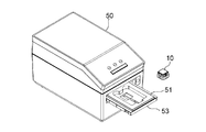
以上のように構成した印体ユニット10に、サーマル加工機50を使用して印面加工を行う手順について説明する。図7に示すように、ホルダ30と枠体13とが嵌合した最終嵌合状態にさせた印体ユニット10を、アタッチメント51の収納部52内に嵌め込んで確実にセットする。このアタッチメント51は長方形の板状のものであり、サーマル加工機50のトレー53に収納可能な構造となっている。
A procedure for performing stamp surface processing on the
次いで、図8に示すように、アタッチメント51をサーマル加工機50のトレー53内に収納すると、その後はサーマル加工機50の中でプログラムの指示に従い、サーマルヘッドにより印字体12に印面が形成されることとなる。このサーマルヘッドによる印面加工においては、入力したデータに基づいて高精度に印面パターンが作成されることとなる。
なお、図9に示すように、サーマル加工機50に予め収納したアタッチメント51に、ホルダ30と枠体13とが嵌合した最終嵌合状態にさせた印体ユニット10をセットしてから加工を行うこともできる。
Next, as shown in FIG. 8, when the
As shown in FIG. 9, the
そして、印面の加工が終了した後は、サーマル加工機50からアタッチメント51を引き出して、ホルダ30と枠体13とが嵌合した最終嵌合状態の印体ユニット10を取り出すことができる。
Then, after the processing of the stamp surface is completed, the
以上説明した実施形態の印体ユニット10によれば、ケース体16と枠体13との間に弾性体を備えたことにより、印字体12とインキ吸蔵体15とを、弾性体の変形距離だけ離隔させることができる。そのため、未加工の印体ユニット10に不測の外力が加えられたとしても、印字体12とインキ吸蔵体15とが接触せず、印字体12へのインキの浸透を未然に防ぐことができる。これにより、印面加工時の不具合を引き起こす要因を排除し、印面の熱加工制御性を十分確保することができる。
According to the
また、弾性体が、インキ吸蔵体15と印字体12とを常時離隔する方向に付勢する弾性反発体であること、そして好ましくは弧状の板バネ20であることにより、仮に、弾性反発力よりも強い外力が一時的に作用して印字体12とインキ吸蔵体15とが接触したとしても、その反発力によってこれらが押し戻すことができるので、印字体12へのインキの浸透開始をより確実に防ぐことができる。
Further, since the elastic body is an elastic repulsive body that always urges the
10 印体ユニット 12 印字体
13 枠体 14 係合肢
14a 爪部 15 インキ吸蔵体
16 ケース体 16a フランジ部
17 壁 18 孔
20 板バネ(弾性反発体) 30 ホルダ
30a ノッチ 40 キャップ
50 サーマル加工機 51 アタッチメント
10
Claims (5)
Priority Applications (4)
| Application Number | Priority Date | Filing Date | Title |
|---|---|---|---|
| JP2016192369A JP6860809B2 (en) | 2016-09-29 | 2016-09-29 | Stamp unit |
| US15/701,693 US20180086124A1 (en) | 2016-09-29 | 2017-09-12 | Stamp unit |
| CN201710856003.9A CN107878052B (en) | 2016-09-29 | 2017-09-21 | Stamp body unit and stamp having the same |
| EP17192876.5A EP3300914B1 (en) | 2016-09-29 | 2017-09-25 | Stamp unit |
Applications Claiming Priority (1)
| Application Number | Priority Date | Filing Date | Title |
|---|---|---|---|
| JP2016192369A JP6860809B2 (en) | 2016-09-29 | 2016-09-29 | Stamp unit |
Publications (2)
| Publication Number | Publication Date |
|---|---|
| JP2018051997A JP2018051997A (en) | 2018-04-05 |
| JP6860809B2 true JP6860809B2 (en) | 2021-04-21 |
Family
ID=59966633
Family Applications (1)
| Application Number | Title | Priority Date | Filing Date |
|---|---|---|---|
| JP2016192369A Active JP6860809B2 (en) | 2016-09-29 | 2016-09-29 | Stamp unit |
Country Status (4)
| Country | Link |
|---|---|
| US (1) | US20180086124A1 (en) |
| EP (1) | EP3300914B1 (en) |
| JP (1) | JP6860809B2 (en) |
| CN (1) | CN107878052B (en) |
Family Cites Families (22)
| Publication number | Priority date | Publication date | Assignee | Title |
|---|---|---|---|---|
| US2040940A (en) * | 1935-06-14 | 1936-05-19 | Austin C Johnson | Stamp support and pad |
| US2623460A (en) * | 1950-02-06 | 1952-12-30 | Brenner | Pocket name imprinter |
| US2778306A (en) * | 1953-08-28 | 1957-01-22 | Carl C Harris | Sealed stamp pad |
| US3035516A (en) * | 1958-08-18 | 1962-05-22 | Lee Brothers Company | Stencil device |
| US3442209A (en) * | 1966-10-04 | 1969-05-06 | Takaji Funahashi | Rubber stamp |
| US4172419A (en) * | 1977-12-05 | 1979-10-30 | Munyon Gary D | Pre-linked stamp construction |
| US4289070A (en) * | 1979-06-26 | 1981-09-15 | Cosco Industries, Inc. | Rubber stamp |
| CN2062279U (en) * | 1990-03-16 | 1990-09-19 | 高锋 | Continuously automatic ink-feeding seal |
| CN2122416U (en) * | 1990-11-18 | 1992-11-18 | 阎滇亮 | Rolling seal |
| JP3028359B2 (en) * | 1993-10-29 | 2000-04-04 | サンビー株式会社 | Penetrated rubber stamp |
| JP3008344U (en) * | 1994-08-29 | 1995-03-14 | 谷川商事株式会社 | Liquid penetration stamp spring |
| US7334342B1 (en) * | 1998-02-27 | 2008-02-26 | William Ack Barr | Marking device having marking members |
| US6226882B1 (en) * | 1998-02-27 | 2001-05-08 | William A. Barr | Cutout marking device for marking sheet material |
| US6892637B2 (en) * | 2003-02-28 | 2005-05-17 | Craig J. Petersen | Self-inking stamp with ink cartridge barrier |
| US6945172B1 (en) * | 2004-06-10 | 2005-09-20 | Shiny Shih | Housing assembly for a self-inking stamp |
| EE200400117A (en) * | 2004-10-19 | 2006-06-15 | Humal Leo-Henn | A method for making an ink-stamp and a stamping body |
| US8006615B1 (en) * | 2007-12-05 | 2011-08-30 | Zoya, Inc. | Stencil stamp set |
| AT507833A3 (en) * | 2009-01-30 | 2013-06-15 | Trodat Gmbh | STAMP AND PUNCH CUSHION FOR A SELF-STAINED STAMP |
| AT509375A1 (en) * | 2010-01-27 | 2011-08-15 | Colop Stempelerzeugung Skopek | COLOR STORAGE UNIT FOR HAND STAMP |
| CN102922888A (en) * | 2012-11-15 | 2013-02-13 | 苏州合亚信息技术有限公司 | Self-balancing constant-pressure seal seat used for high-speed automatic stamping machine |
| JP2016139205A (en) | 2015-01-26 | 2016-08-04 | シヤチハタ株式会社 | Stamp order placement/reception system |
| JP6593203B2 (en) * | 2016-01-29 | 2019-10-23 | シヤチハタ株式会社 | Stamping machine |
-
2016
- 2016-09-29 JP JP2016192369A patent/JP6860809B2/en active Active
-
2017
- 2017-09-12 US US15/701,693 patent/US20180086124A1/en not_active Abandoned
- 2017-09-21 CN CN201710856003.9A patent/CN107878052B/en active Active
- 2017-09-25 EP EP17192876.5A patent/EP3300914B1/en active Active
Also Published As
| Publication number | Publication date |
|---|---|
| CN107878052A (en) | 2018-04-06 |
| EP3300914B1 (en) | 2019-05-15 |
| EP3300914A1 (en) | 2018-04-04 |
| JP2018051997A (en) | 2018-04-05 |
| US20180086124A1 (en) | 2018-03-29 |
| CN107878052B (en) | 2021-10-26 |
Similar Documents
| Publication | Publication Date | Title |
|---|---|---|
| US11651709B2 (en) | Multilayered sheet assembly and a method for forming a sign | |
| JP6860809B2 (en) | Stamp unit | |
| JP2008273114A (en) | Liquid container, reproduction method of liquid container, use method of reproduction liquid container, and sealing method in liquid container | |
| US10220740B2 (en) | Vehicle seat and manufacturing method therefor | |
| JP2015193965A5 (en) | Sheet manufacturing apparatus and sheet | |
| JP2012153102A (en) | Method for manufacturing porous stamp | |
| US20160166722A1 (en) | Scented Lenticular Air Freshener | |
| KR101768406B1 (en) | Block printing method | |
| US10336457B2 (en) | Seat rail cover for covering a seat rail in a vehicle floor and method for manufacturing a seat rail cover | |
| JP6372312B2 (en) | Porous stamp unit | |
| JP2011101753A (en) | Jigsaw puzzle and method for manufacturing the same | |
| JP3218594U (en) | accessory | |
| JP2016190702A (en) | Thermal transfer sheet with lead film, and combination of thermal transfer sheet with lead film and winding bobbin | |
| JP6508613B2 (en) | Porous seal | |
| JP6401661B2 (en) | Paper craft | |
| JP5640177B2 (en) | Jigsaw puzzle and its manufacturing method | |
| US1136591A (en) | Method of forming stencil-sheets. | |
| JP2016124112A (en) | Porous stamp | |
| JP3199052U (en) | Car with wheels | |
| JP3202094U (en) | Assembly figure | |
| JP5799945B2 (en) | Stamp and plate | |
| US1350993A (en) | Address-stencil | |
| JP2001212925A5 (en) | ||
| US565327A (en) | Printing-stamp | |
| US1167795A (en) | Photographic-printing apparatus. |
Legal Events
| Date | Code | Title | Description |
|---|---|---|---|
| A621 | Written request for application examination |
Free format text: JAPANESE INTERMEDIATE CODE: A621 Effective date: 20190717 |
|
| A977 | Report on retrieval |
Free format text: JAPANESE INTERMEDIATE CODE: A971007 Effective date: 20200630 |
|
| A131 | Notification of reasons for refusal |
Free format text: JAPANESE INTERMEDIATE CODE: A131 Effective date: 20200721 |
|
| A521 | Request for written amendment filed |
Free format text: JAPANESE INTERMEDIATE CODE: A523 Effective date: 20200914 |
|
| TRDD | Decision of grant or rejection written | ||
| A01 | Written decision to grant a patent or to grant a registration (utility model) |
Free format text: JAPANESE INTERMEDIATE CODE: A01 Effective date: 20210225 |
|
| A61 | First payment of annual fees (during grant procedure) |
Free format text: JAPANESE INTERMEDIATE CODE: A61 Effective date: 20210310 |
|
| R150 | Certificate of patent or registration of utility model |
Ref document number: 6860809 Country of ref document: JP Free format text: JAPANESE INTERMEDIATE CODE: R150 |
|
| R250 | Receipt of annual fees |
Free format text: JAPANESE INTERMEDIATE CODE: R250 |