JP6859832B2 - Fluid bearing equipment, motors and disk drives - Google Patents
Fluid bearing equipment, motors and disk drives Download PDFInfo
- Publication number
- JP6859832B2 JP6859832B2 JP2017088596A JP2017088596A JP6859832B2 JP 6859832 B2 JP6859832 B2 JP 6859832B2 JP 2017088596 A JP2017088596 A JP 2017088596A JP 2017088596 A JP2017088596 A JP 2017088596A JP 6859832 B2 JP6859832 B2 JP 6859832B2
- Authority
- JP
- Japan
- Prior art keywords
- dynamic pressure
- fluid bearing
- pressure groove
- grooves
- bearing device
- Prior art date
- Legal status (The legal status is an assumption and is not a legal conclusion. Google has not performed a legal analysis and makes no representation as to the accuracy of the status listed.)
- Active
Links
- 239000012530 fluid Substances 0.000 title claims description 51
- 230000002093 peripheral effect Effects 0.000 claims description 50
- 230000001788 irregular Effects 0.000 claims description 5
- 239000010687 lubricating oil Substances 0.000 claims description 2
- 230000005291 magnetic effect Effects 0.000 description 19
- 238000010586 diagram Methods 0.000 description 8
- 230000004907 flux Effects 0.000 description 3
- 239000007789 gas Substances 0.000 description 3
- 239000001307 helium Substances 0.000 description 2
- 229910052734 helium Inorganic materials 0.000 description 2
- SWQJXJOGLNCZEY-UHFFFAOYSA-N helium atom Chemical compound [He] SWQJXJOGLNCZEY-UHFFFAOYSA-N 0.000 description 2
- 229910052751 metal Inorganic materials 0.000 description 2
- 239000002184 metal Substances 0.000 description 2
- 230000004048 modification Effects 0.000 description 2
- 238000012986 modification Methods 0.000 description 2
- 125000006850 spacer group Chemical group 0.000 description 2
- 239000010935 stainless steel Substances 0.000 description 2
- 229910001220 stainless steel Inorganic materials 0.000 description 2
- 229910000838 Al alloy Inorganic materials 0.000 description 1
- UFHFLCQGNIYNRP-UHFFFAOYSA-N Hydrogen Chemical compound [H][H] UFHFLCQGNIYNRP-UHFFFAOYSA-N 0.000 description 1
- 229910052782 aluminium Inorganic materials 0.000 description 1
- XAGFODPZIPBFFR-UHFFFAOYSA-N aluminium Chemical compound [Al] XAGFODPZIPBFFR-UHFFFAOYSA-N 0.000 description 1
- 238000013459 approach Methods 0.000 description 1
- 238000005266 casting Methods 0.000 description 1
- 230000005294 ferromagnetic effect Effects 0.000 description 1
- WABPQHHGFIMREM-UHFFFAOYSA-N lead(0) Chemical compound [Pb] WABPQHHGFIMREM-UHFFFAOYSA-N 0.000 description 1
- 239000000696 magnetic material Substances 0.000 description 1
- 239000000463 material Substances 0.000 description 1
- 238000007789 sealing Methods 0.000 description 1
- 230000000087 stabilizing effect Effects 0.000 description 1
Images


Classifications
-
- F—MECHANICAL ENGINEERING; LIGHTING; HEATING; WEAPONS; BLASTING
- F16—ENGINEERING ELEMENTS AND UNITS; GENERAL MEASURES FOR PRODUCING AND MAINTAINING EFFECTIVE FUNCTIONING OF MACHINES OR INSTALLATIONS; THERMAL INSULATION IN GENERAL
- F16C—SHAFTS; FLEXIBLE SHAFTS; ELEMENTS OR CRANKSHAFT MECHANISMS; ROTARY BODIES OTHER THAN GEARING ELEMENTS; BEARINGS
- F16C17/00—Sliding-contact bearings for exclusively rotary movement
- F16C17/12—Sliding-contact bearings for exclusively rotary movement characterised by features not related to the direction of the load
-
- G—PHYSICS
- G11—INFORMATION STORAGE
- G11B—INFORMATION STORAGE BASED ON RELATIVE MOVEMENT BETWEEN RECORD CARRIER AND TRANSDUCER
- G11B19/00—Driving, starting, stopping record carriers not specifically of filamentary or web form, or of supports therefor; Control thereof; Control of operating function ; Driving both disc and head
- G11B19/20—Driving; Starting; Stopping; Control thereof
- G11B19/2009—Turntables, hubs and motors for disk drives; Mounting of motors in the drive
- G11B19/2036—Motors characterized by fluid-dynamic bearings
-
- F—MECHANICAL ENGINEERING; LIGHTING; HEATING; WEAPONS; BLASTING
- F16—ENGINEERING ELEMENTS AND UNITS; GENERAL MEASURES FOR PRODUCING AND MAINTAINING EFFECTIVE FUNCTIONING OF MACHINES OR INSTALLATIONS; THERMAL INSULATION IN GENERAL
- F16C—SHAFTS; FLEXIBLE SHAFTS; ELEMENTS OR CRANKSHAFT MECHANISMS; ROTARY BODIES OTHER THAN GEARING ELEMENTS; BEARINGS
- F16C17/00—Sliding-contact bearings for exclusively rotary movement
- F16C17/10—Sliding-contact bearings for exclusively rotary movement for both radial and axial load
- F16C17/102—Sliding-contact bearings for exclusively rotary movement for both radial and axial load with grooves in the bearing surface to generate hydrodynamic pressure
-
- F—MECHANICAL ENGINEERING; LIGHTING; HEATING; WEAPONS; BLASTING
- F16—ENGINEERING ELEMENTS AND UNITS; GENERAL MEASURES FOR PRODUCING AND MAINTAINING EFFECTIVE FUNCTIONING OF MACHINES OR INSTALLATIONS; THERMAL INSULATION IN GENERAL
- F16C—SHAFTS; FLEXIBLE SHAFTS; ELEMENTS OR CRANKSHAFT MECHANISMS; ROTARY BODIES OTHER THAN GEARING ELEMENTS; BEARINGS
- F16C33/00—Parts of bearings; Special methods for making bearings or parts thereof
- F16C33/02—Parts of sliding-contact bearings
- F16C33/04—Brasses; Bushes; Linings
- F16C33/06—Sliding surface mainly made of metal
- F16C33/10—Construction relative to lubrication
- F16C33/1025—Construction relative to lubrication with liquid, e.g. oil, as lubricant
- F16C33/106—Details of distribution or circulation inside the bearings, e.g. details of the bearing surfaces to affect flow or pressure of the liquid
- F16C33/107—Grooves for generating pressure
-
- H—ELECTRICITY
- H02—GENERATION; CONVERSION OR DISTRIBUTION OF ELECTRIC POWER
- H02K—DYNAMO-ELECTRIC MACHINES
- H02K7/00—Arrangements for handling mechanical energy structurally associated with dynamo-electric machines, e.g. structural association with mechanical driving motors or auxiliary dynamo-electric machines
- H02K7/08—Structural association with bearings
-
- F—MECHANICAL ENGINEERING; LIGHTING; HEATING; WEAPONS; BLASTING
- F16—ENGINEERING ELEMENTS AND UNITS; GENERAL MEASURES FOR PRODUCING AND MAINTAINING EFFECTIVE FUNCTIONING OF MACHINES OR INSTALLATIONS; THERMAL INSULATION IN GENERAL
- F16C—SHAFTS; FLEXIBLE SHAFTS; ELEMENTS OR CRANKSHAFT MECHANISMS; ROTARY BODIES OTHER THAN GEARING ELEMENTS; BEARINGS
- F16C2240/00—Specified values or numerical ranges of parameters; Relations between them
-
- F—MECHANICAL ENGINEERING; LIGHTING; HEATING; WEAPONS; BLASTING
- F16—ENGINEERING ELEMENTS AND UNITS; GENERAL MEASURES FOR PRODUCING AND MAINTAINING EFFECTIVE FUNCTIONING OF MACHINES OR INSTALLATIONS; THERMAL INSULATION IN GENERAL
- F16C—SHAFTS; FLEXIBLE SHAFTS; ELEMENTS OR CRANKSHAFT MECHANISMS; ROTARY BODIES OTHER THAN GEARING ELEMENTS; BEARINGS
- F16C2370/00—Apparatus relating to physics, e.g. instruments
- F16C2370/12—Hard disk drives or the like
-
- F—MECHANICAL ENGINEERING; LIGHTING; HEATING; WEAPONS; BLASTING
- F16—ENGINEERING ELEMENTS AND UNITS; GENERAL MEASURES FOR PRODUCING AND MAINTAINING EFFECTIVE FUNCTIONING OF MACHINES OR INSTALLATIONS; THERMAL INSULATION IN GENERAL
- F16C—SHAFTS; FLEXIBLE SHAFTS; ELEMENTS OR CRANKSHAFT MECHANISMS; ROTARY BODIES OTHER THAN GEARING ELEMENTS; BEARINGS
- F16C2380/00—Electrical apparatus
- F16C2380/26—Dynamo-electric machines or combinations therewith, e.g. electro-motors and generators
Landscapes
- Engineering & Computer Science (AREA)
- General Engineering & Computer Science (AREA)
- Mechanical Engineering (AREA)
- Physics & Mathematics (AREA)
- Fluid Mechanics (AREA)
- Chemical & Material Sciences (AREA)
- Oil, Petroleum & Natural Gas (AREA)
- Power Engineering (AREA)
- Connection Of Motors, Electrical Generators, Mechanical Devices, And The Like (AREA)
- Sliding-Contact Bearings (AREA)
- Rotational Drive Of Disk (AREA)
Description
本発明は、流体軸受装置、モータおよびディスク駆動装置に関する。 The present invention relates to a fluid bearing device, a motor and a disk drive device.
従来、ハードディスクドライブ等のディスク駆動装置が知られている。ディスク駆動装置には、ディスクを回転させるためのモータが搭載されている。モータは、回転体と非回転体との間に動圧軸受を設けて、高速回転を行う。従来の回転装置については、例えば、特開2000−199520号公報に記載されている。当該公報の回転装置は、ラジアル固定部材と、ラジアル固定部材に対して回転可能な回転ユニットとを備える。ラジアル固定部材と回転ユニットとに対向する動圧軸受部には、複数の動圧発生溝が等間隔に形成されている。複数の動圧発生溝それぞれは、溝の長さ、または、溝の深さが異なる。これにより、高速回転で安定した回転性能が得られる回転装置を実現している。
特開2000−199520号公報に記載の回転装置では、動圧発生溝は、回転軸の周方向に等間隔に形成されている。動圧発生溝を等間隔に形成すると、その間隔に合った特定周波数の騒音が顕著に現れることがある。この場合、特開2000−199520号公報に記載の回転装置では、特定周波数の騒音を抑制できない。 In the rotating device described in JP-A-2000-199520, the dynamic pressure generating grooves are formed at equal intervals in the circumferential direction of the rotating shaft. When the dynamic pressure generating grooves are formed at equal intervals, noise of a specific frequency corresponding to the intervals may remarkably appear. In this case, the rotating device described in Japanese Patent Application Laid-Open No. 2000-199520 cannot suppress noise of a specific frequency.
このような問題を鑑みて、本発明の目的は、回転部材の回転時に、特定周波数の騒音の発生を抑制する流体軸受装置、モータおよびディスク駆動装置を提供することである。 In view of such a problem, an object of the present invention is to provide a fluid bearing device, a motor and a disk drive device that suppress the generation of noise of a specific frequency when the rotating member rotates.
上記課題を解決するため、本発明は、流体軸受装置であって、静止部材と、前記静止部材に対して回転軸を中心に回転する回転部材と、を備え、前記静止部材の軸受面および前記回転部材の軸受面は、流体が充填された微小間隙を介して対向し、前記軸受面の少なくとも一方は、第1動圧溝列を有し、前記第1動圧溝列は、周方向に沿って、全て異なる間隔で配列された複数の第1動圧溝を有し、隣接する前記第1動圧溝の周方向の間隔は、不定である。 In order to solve the above problems, the present invention is a fluid bearing device, comprising a stationary member and a rotating member that rotates about a rotation axis with respect to the stationary member, the bearing surface of the stationary member, and the above. The bearing surfaces of the rotating member face each other through a small gap filled with fluid, and at least one of the bearing surfaces has a first dynamic pressure groove row, and the first dynamic pressure groove row is in the circumferential direction. along, have a plurality of first dynamic pressure grooves that are arranged in all different intervals in the circumferential direction of the spacing of adjacent said first dynamic pressure groove is indeterminate.
本発明によれば、回転部材の回転時に、特定周波数の騒音の発生を抑制する。 According to the present invention, the generation of noise of a specific frequency is suppressed when the rotating member is rotated.
以下、本願の例示的な実施形態について、図面を参照しながら説明する。なお、本願では、「流体軸受装置」を備える「モータ」の一例として、スピンドルモータを例に挙げて説明する。また、モータの中心軸と平行な方向を「軸方向」、モータの中心軸に直交する方向を「径方向」、モータの中心軸を中心とする円弧に沿う方向を「周方向」、とそれぞれ称する。また、本願では、軸方向を上下方向とし、ベース部に対してステータユニット側を上として、各部の形状や位置関係を説明する。ただし、この上下方向の定義により、本願に係るモータ、およびディスク駆動装置の使用時の向きを限定する意図はない。 Hereinafter, exemplary embodiments of the present application will be described with reference to the drawings. In this application, a spindle motor will be described as an example of a "motor" including a "fluid bearing device". In addition, the direction parallel to the central axis of the motor is the "axial direction", the direction orthogonal to the central axis of the motor is the "radial direction", and the direction along the arc centered on the central axis of the motor is the "circumferential direction". Refer to. Further, in the present application, the shape and positional relationship of each part will be described with the axial direction in the vertical direction and the stator unit side facing up with respect to the base part. However, this definition of the vertical direction does not intend to limit the orientation of the motor and the disk drive device according to the present application when used.
また、本願において「平行な方向」とは、略平行な方向も含む。また、本願において「直交する方向」とは、略直交する方向も含む。 Further, in the present application, the "parallel direction" includes a substantially parallel direction. Further, in the present application, the "orthogonal direction" includes a direction substantially orthogonal to each other.
<1.ディスク駆動装置の構成>
図1は、本願の例示的な実施形態に係るディスク駆動装置100の断面図である。
<1. Disk drive configuration>
FIG. 1 is a cross-sectional view of a
ディスク駆動装置100は、3枚の磁気ディスク101を回転させつつ、磁気ディスク101からの情報の読み出し、磁気ディスク101への情報の書き込みを行うハードディスク装置である。ディスク駆動装置100は、スピンドルモータ1と、3枚の磁気ディスク101と、3つのアクセス部102と、これらを収容するハウジング103とを備える。
The
ハウジング103は、ベース部40と、カバー部材104と、を有する。ベース部40は、後述のスピンドルモータ1の一部でもある。ベース部40は、例えば、鋳造にて成型される。ベース部40は、アルミダイキャストである。ベース部40は開口を有する。カバー部材104は、ベース部40の開口に嵌められる。これにより、ハウジング103が構成される。ハウジング103の内部空間には、後述するスピンドルモータ1のシャフト10、回転部20、およびステータユニット30、が収容される。ベース部40とカバー部材104とは、ハウジング103内の気密性が損なわれないように、組み合わされる。
The
ハウジング103の内部空間には、空気よりも低密度の気体、例えば、ヘリウムガスが充填されている。ヘリウムガスが充填されることで、磁気ディスク101の回転時の風切り音等が低減する。なお、ハウジング103の内部空間には、水素ガス、空気等が充填されていてもよい。
The internal space of the
複数の磁気ディスク101は、情報が記録される媒体である。複数の磁気ディスク101は、間に、スペーサ105と、スペーサ106とが配置され、上下方向に延びる回転軸9に沿って積層される。そして、複数の磁気ディスク101は、後に詳述するスピンドルモータ1に支持される。複数の磁気ディスク101は、スピンドルモータ1により、回転軸9を中心として回転する。
The plurality of
アクセス部102は、ヘッド107と、アーム108と、ヘッド移動機構109とを有する。ヘッド107は、磁気ディスク101の表面に接近して、磁気ディスク101に記録された情報の読み出し、および、磁気ディスク101への情報の書き込み、の少なくともいずれか一方を磁気的に行う。ヘッド107は、アーム108に支持される。アーム108は、ヘッド移動機構109に支持される。
The
<2.スピンドルモータの構成>
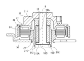
図2は、図1のスピンドルモータ1の拡大図である。
<2. Spindle motor configuration>
FIG. 2 is an enlarged view of the
スピンドルモータ1は、シャフト10と、環状部材11と、回転部20と、ステータユニット30と、ベース部40と、を有する。本願の例示的な各実施形態にかかるスピンドルモータ1は、三相モータである。
The
シャフト10は、回転軸9に沿って配置された、略円柱形状の部材である。シャフト10は、回転部20を、回転軸9を中心として回転可能に支持する。シャフト10は、例えば、ステンレス等の金属により形成される。シャフト10の上端部は、ハウジング103のカバー部材104に固定される。シャフト10の下端部は、ベース部40に固定される。
The
シャフト10の外周面には、2つの環状部材11が設けられる。2つの環状部材11は、軸方向に間隔を空けて、シャフト10の上下に設けられる。環状部材11は、シャフト10の外周面から径方向外側に突出し、シャフト10に固定され、または、シャフト10と一体成形される部材である。なお、以下の説明では、シャフト10の軸方向上側に固定された環状部材11について説明する。
Two
環状部材11の外周面において、軸方向の略中央から上部の外周面11Aは、上向きに漸次小径となる。また、環状部材11の外周面において、軸方向の略中央から下部の外周面11Bは、下向きに漸次小径となる。シャフト10と、環状部材11と、により、本願の例示的な実施形態にかかる「静止部材」が構成される。
On the outer peripheral surface of the
回転部20は、シャフト10および環状部材11に対して、回転軸9を中心に回転する回転部材である。回転部20は、スリーブ21と、ロータハブ22と、クランプ部材23(図1参照)と、ロータマグネット24と、ヨーク25とを備える。
The rotating
スリーブ21は、回転軸9を中心として、シャフト10および環状部材11に対して、回転可能である。スリーブ21は、環状部材11の外周面11Bと対向する第1内周面21Aと、シャフト10の外周面と対向する第2内周面21Bと、を有する。スリーブ21の第1内周面21Aおよび第2内周面21Bと、シャフト10の外周面、および、環状部材11の外周面11Bとは、潤滑オイル等の流体が充填された微小間隙を介し対向する。第2内周面21Bは、径方向外側に窪む溝21Cを有する。溝21Cは、流体の界面安定用のための空気循環用の溝である。
The
第1内周面21Aは、環状部材11の外周面11Bに対向するスラスト軸受面である。第2内周面21Bは、シャフト10の外周面に対向するラジアル軸受面である。第1内周面21Aおよび第2内周面21Bそれぞれには、流体の動圧を発生させるための動圧溝列が設けられる。動圧溝列は、後に詳述する。シャフト10と、環状部材11と、スリーブ21とで、本発明の「流体軸受装置」が構成される。
The first inner
スリーブ21の軸方向上側および軸方向下側それぞれには、スピンドルモータ1の外部への流体の漏洩を防ぐためにシール部材210が設けられる。シール部材210は、環状部材11、および、スリーブ21の上面および下面を覆い、スリーブ12に固定される。
ロータハブ22は円筒状である。ロータハブ22は、スリーブ21に支持される。そして、ロータハブ22は、スリーブ21と共に、回転軸9を中心として回転する。スリーブ21とロータハブ22とは、一繋がりの部材で形成されてもよいし、別部材であってもよい。スリーブ21およびロータハブ22の材料には、例えば、アルミニウム合金または強磁性ステンレス鋼等の金属が使用される。
The
クランプ部材23は、ロータハブ22に支持される。図1に示すように、クランプ部材23は、ロータハブ22との間に、複数の磁気ディスク101を支持する。これにより、複数の磁気ディスク101は、回転部20に支持され、回転軸9を中心として回転する。
The
ロータマグネット24は、ヨーク25を介して、ロータハブ22の内周面に固定される。ロータマグネット24は、回転軸9を中心とする円環形状をなす。ロータマグネット24の内周面は、周方向に沿ってN極とS極とが交互に配列された磁極面である。
The
ステータユニット30は、ロータハブ22の径方向内側に配置される。ステータユニット30は、回転部20を回転させるトルクを発生させる。ステータユニット30は、複数のコイル31と、ステータコア32とを有する。
The
ステータコア32は、回転軸9を中心とする円環状の磁性体が、複数積層された積層構造体である。ステータコア32は、ベース部40に固定される。ステータコア32は、径方向外側に突出する複数のティースを有する。
The
複数のコイル31は、複数のティースに巻かれ、回転軸9を中心として環状に配置される。複数のコイル31は、3つのコイル群により構成される。3つのコイル群は、それぞれU相用、V相用、W相用である。各コイル群は、1つの導線により構成される。コイル31およびステータコア32と、ロータマグネット33とは、径方向に対向する。コイル31に駆動電流が与えられると、径方向の磁束が発生する。発生した磁束は、ロータマグネット33の磁束と互いに作用し、回転軸9を中心として回転部20を回転させるためのトルクを発生させる。
The plurality of
<3.動圧溝について>
<3.1.第1内周面21Aの動圧溝について>
<3. About dynamic pressure groove >
<3.1. About the dynamic pressure groove of the first inner
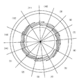
図3は、回転軸9の上側から視た、スリーブ21の第1内周面21Aの平面図である。
FIG. 3 is a plan view of the first inner
第1内周面21Aには、第1動圧溝列51と、第2動圧溝列52とが設けられる。なお、第1動圧溝列51と第2動圧溝列52とは、同一の第1内周面21A上に設けられるが、説明の便宜上、図3では、第2動圧溝列52は、破線で示す。
The first inner
第1動圧溝列51は、複数(この例では、14本)の第1動圧溝511を有する。第1動圧溝511は、第1端と、第2端とを繋ぐ線が曲線状となる三日月形状である。第1動圧溝511は、第1端が第2端よりも、径方向の内側に配置される。複数の第1動圧溝511は、周方向に沿って、不定な間隔で不均等に配列される。また、複数の第1動圧溝511それぞれは、図3に示す線分(A)に示すように、径方向において、一の第1動圧溝511の第1端と、他の少なくとも二つの第1動圧溝511とが重なって配置される。
The first dynamic
ここで、「不定な間隔」とは、隣接する第1動圧溝511の周方向の間隔が一定でないことを言う。より詳しくは、隣接する第1動圧溝511の第1端近傍の間隔と、第2端近傍の間隔とが異なる。また、「不均等」とは、14本の第1動圧溝511がすべて異なる間隔で周方向に配列されることを言う。「不均等」については、後に詳述する。
Here, the "indefinite interval" means that the interval in the circumferential direction of the adjacent first
第2動圧溝列52は、複数(この例では、20本)の第2動圧溝521を有する。第2動圧溝521は、第1端と、第2端とを繋ぐ線が曲線状となる三日月形状である。第2動圧溝521は、第2端が第1端よりも、径方向の外側に配置される。複数の第2動圧溝521は、第1動圧溝511よりも径方向外側において、周方向に沿って、不定な間隔で不均等に配列される。複数の第2動圧溝521それぞれは、複数の第1動圧溝511それぞれと不連続である。また、複数の第2動圧溝521それぞれは、図3に示す線分(B)に示すように、径方向において、一の第1動圧溝511の第2端と、少なくとも三つ(図3では4つ)の第2動圧溝521とが重なって配置される。
The second dynamic
なお、スリーブ21の下側の第1内周面21Aにも、図3と同様に、第1動圧溝列、および、第2動圧溝列が設けられている。
The first inner
図4は、不均等に配列した複数の第1動圧溝511を説明するための図である。図5は、不均等に配列した複数の第2動圧溝521を説明するための図である。図6は、回転軸9を中心とした、第1動圧溝511および第2動圧溝521それぞれの配置角度を数値で表した図である。なお、図4では、第2動圧溝521の図示は省略している。また、図5では、第1動圧溝511の図示は省略している。
FIG. 4 is a diagram for explaining a plurality of first
図6のカッコ書きの数値、例えば(1)等は、図4および図5のカッコ書きの数値に対応している。例えば、図4に示す(1)における角度は、25.20°である。また、図5に示す(1)における角度は、21.84°である。 The numbers in parentheses in FIG. 6, for example (1), correspond to the numbers in parentheses in FIGS. 4 and 5. For example, the angle in (1) shown in FIG. 4 is 25.20 °. The angle in (1) shown in FIG. 5 is 21.84 °.
14本の第1動圧溝511は、回転軸9から特定の径方向を開始位置として、周方向に沿って、25.20°、29.63°、21.32°、21.18°、33.12°、33.80°、22.56°、19.08°、22.42°、24.23°、29.69°、34.00°、25.69°、18.07°の間隔で配列される。本実施形態では、複数の第1動圧溝511の第1端が、上記間隔となっている。ただし、複数の第1動圧溝511の第2端が、上記間隔となっていてもよい。また、複数の第1動圧溝511の中心部が、上記間隔となっていてもよい。
The 14 first
同様に、20本の第2動圧溝521は、回転軸9から特定の径方向を開始位置として、周方向に沿って、21.84°、21.67°、19.77°、16.78°、14.27°、14.19°、16.88°、20.09°、20.83°、18.65°、16.26°、16.60°、19.38°、21.39°、20.08°、16.41°、13.68°、14.10°、17.00°、20.13°の間隔で配列される。本実施形態では、複数の第2動圧溝521の第2端が、上記間隔となっている。ただし、複数の第2動圧溝521の第1端が、上記間隔となっていてもよい。また、複数の第2動圧溝521の中心部が、上記間隔となっていてもよい。
Similarly, the 20 second
<3.2.第2内周面21Bの動圧溝について>
図7は、径方向内側から視た、スリーブ21の第1内周面21Aおよび第2内周面21Bの平面図である。図7では、シャフト10を破線で示す。また、第1動圧溝511および第2動圧溝521は、三日月形状であるが、図7では、直線状で示す。
<3.2. About the dynamic pressure groove of the second inner
FIG. 7 is a plan view of the first inner
第2内周面21Bには、第3動圧溝列53が設けられる。第3動圧溝列53は、複数の第3動圧溝531が、周方向に沿って配列される。第3動圧溝531は、等間隔に配列されてもよいし、不等間隔に設けられてもよい。また、第3動圧溝531の形状は特に限定されない。また、第3動圧溝531の総数は、適宜変更可能であるが、第1動圧溝511の総数をN1、第2動圧溝521の総数をN2、第3動圧溝531の総数をN3で表すと、N1<N3<N2を満たすことが好ましい。例えば、前記のように、第1動圧溝の総数が14本、第2動圧溝521の総数が20本である場合、第3動圧溝531の総数は、例えば15本である。
A third dynamic
以上のように、スリーブ21の第1内周面21Aおよび第2内周面21Bに、動圧溝を設けることで、スリーブ21とシャフト10および環状部材11とが微小間隙を介して接触することを抑制可能である。そして、スラスト軸受面である第1内周面21Aに、不定な間隔で不等配に複数の第1動圧溝511を設けることで、特定周波数の騒音の発生を抑制できる。また、スラスト軸受面である第1内周面21Aに、複数の第2動圧溝521を不定な間隔で不均等にさらに設けることで、第1動圧溝列51および第2動圧溝列52の双方について、特定周波数の騒音の発生を抑制できる。
As described above, by providing the dynamic pressure grooves on the first inner
<4.変形例>
以上、本発明の実施形態について説明したが、本発明は、上記の実施形態に限定されるものではない。
<4. Modification example>
Although the embodiments of the present invention have been described above, the present invention is not limited to the above embodiments.
第1動圧溝511の数、および、第2動圧溝521の数は、実施形態の数値に限定されない。第1動圧溝511の数、および、第2動圧溝521の数は、スピンドルモータ1の回転数に応じて、適宜変更可能である。例えば、第1動圧溝511の総数をN、スピンドルモータ1の回転数をRで表すと、総数Nは、500<(R/60)*N<5000を満たすことが好ましい。第2動圧溝521についても同様である。
The number of the first
また、複数の第1動圧溝511を配列する間隔は、実施形態の数値に限定されない。複数の第1動圧溝511は、第1動圧溝511の総数をNで表すと、(360°/N)±10°、または、(360°/N)±(150°/N)の間隔で、周方向に沿って配列されていればよい。第2動圧溝521についても同様である。
Further, the interval for arranging the plurality of first
上記の実施形態では、第1動圧溝列51および第2動圧溝列52は、スリーブ21の第1内周面21Aに設けられているが、環状部材11の外周面11Bに設けられてもよい。また、第3動圧溝列53は、スリーブ21の第2内周面21Bに設けられているが、シャフト10の外周面に設けられてもよい。
In the above embodiment, the first dynamic
また、流体軸受装置の構成は、上記の実施形態に限定されない。例えば、流体軸受装置は、シャフト10が、回転軸9を中心として回転する構成であってもよい。以下に、流体軸受装置の2つの例を挙げる。図8および図9は、流体軸受装置の別の構成例を示す図である。
Further, the configuration of the fluid bearing device is not limited to the above embodiment. For example, the fluid bearing device may have a configuration in which the
図8に示す流体軸受装置では、シャフト10の径方向外側に、微小間隙を介して、スリーブ211が配置される。また、シャフト10の下側に、キャップ212が配置される。シャフト10は、スリーブ211およびキャップ212により、回転可能に支持される。シャフト10の上側端部には、ロータハブ22が固定される。そして、シャフト10と、ロータハブ22とは共に回転する。対向する、シャフト10の外周面10Aと、スリーブ211の内周面211Aの一方には、第3動圧溝列が設けられる。第3動圧溝列は、軸方向において、間隔を空けた二か所に、設けられてもよいし、一か所にのみ設けられてもよい。
In the fluid bearing device shown in FIG. 8, the
シャフト10の下側端部には、環状部材111が固定される。シャフト10と、環状部材111とは、別部材であってもよいし、単一の部材であってもよい。環状部材111の軸方向の上面111Aは、スリーブ211の下面211Bと微小間隙を介して対向する。また、環状部材111の軸方向の下面111Bが、キャップ212の上面212Aと微小間隙を介して対向する。環状部材111の上面111Aと、スリーブ211の下面211Bとの一方には、第1動圧溝列および第2動圧溝列が設けられる。また、環状部材111の下面111Bと、キャップ212の上面212Aとの一方にも、第1動圧溝列および第2動圧溝列が設けられる。
An
図9に示す流体軸受装置では、シャフト10の径方向外側に、微小間隙を介して、軸受ハウジング211およびスリーブ21が配置される。また、シャフト10の下側に、キャップ212が配置される。シャフト10は、スリーブ21、軸受ハウジング211およびキャップ212により、回転可能に支持される。対向するシャフト10の外周面10Aと、スリーブ21の内周面21Dの一方には、第3動圧溝列が設けられる。
In the fluid bearing device shown in FIG. 9, the bearing
シャフト10の下端部は、径方向に突出する。突出した部分の上面10Bは、スリーブ21の下面21Eと、微小間隙を介して軸方向に対向する。また、シャフト10の下面10Cと、キャップ212の上面212Aとは、微小間隙を介して軸方向に対向する。シャフト10の下端部上面10Bと、スリーブ21の下面21Eとの一方には、第1動圧溝列および第2動圧溝列が設けられる。また、シャフト10の下面10Cと、キャップ212の上面212Aとの一方にも、第1動圧溝列および第2動圧溝列が設けられる。
The lower end of the
上記の実施形態および変形例に登場した各要素を、矛盾が生じない範囲で、適宜に組み合わせてもよい。 Each element appearing in the above-described embodiment and modification may be appropriately combined as long as there is no contradiction.
本願は、流体軸受装置、モータおよびディスク駆動装置に利用できる。 The present application can be used for fluid bearing devices, motors and disk drive devices.
1 :スピンドルモータ
9 :回転軸
10 :シャフト
11 :環状部材
20 :回転部
21 :スリーブ
21A :第1内周面
21B :第2内周面
21C :溝
30 :ステータユニット
51 :第1動圧溝列
52 :第2動圧溝列
53 :第3動圧溝列
100 :ディスク駆動装置
511 :第1動圧溝
521 :第2動圧溝
531 :第3動圧溝
1: Spindle motor 9: Rotating shaft 10: Shaft 11: Annular member 20: Rotating part 21:
Claims (16)
静止部材と、
前記静止部材に対して回転軸を中心に回転する回転部材と、
を備え、
前記静止部材の軸受面および前記回転部材の軸受面は、流体が充填された微小間隙を介して対向し、
前記軸受面の少なくとも一方は、第1動圧溝列を有し、
前記第1動圧溝列は、周方向に沿って、全て異なる間隔で配列された複数の第1動圧溝を有し、
隣接する前記第1動圧溝の周方向の間隔は、不定である、
流体軸受装置。 It is a fluid bearing device
With stationary members
A rotating member that rotates about a rotation axis with respect to the stationary member,
With
The bearing surface of the stationary member and the bearing surface of the rotating member face each other through a minute gap filled with fluid.
At least one of the bearing surfaces has a first dynamic groove row.
The first dynamic pressure groove array along the circumferential direction, have a plurality of first dynamic pressure grooves that are arranged in all different intervals,
The distance between the adjacent first dynamic pressure grooves in the circumferential direction is indefinite.
Fluid bearing equipment.
前記軸受面の少なくとも一方は、第2動圧溝列を有し、
前記第2動圧溝列は、前記第1動圧溝列よりも径方向外側に、前記周方向に沿って、不定な間隔で不均等に配列された複数の第2動圧溝を有する、
流体軸受装置。 The fluid bearing device according to claim 1.
At least one of the bearing surfaces has a second dynamic groove row.
The second dynamic pressure groove array has a plurality of second dynamic pressure grooves arranged unevenly at irregular intervals along the circumferential direction on the radial outer side of the first dynamic pressure groove array.
Fluid bearing equipment.
複数の前記第1動圧溝それぞれと、複数の前記第2動圧溝それぞれとは、不連続である、
流体軸受装置。 The fluid bearing device according to claim 2.
Each of the plurality of the first dynamic pressure grooves and each of the plurality of the second dynamic pressure grooves are discontinuous.
Fluid bearing equipment.
前記第1動圧溝および前記第2動圧溝は、それぞれ、前記周方向の一端である第1端と、前記周方向の他端である第2端とを有し、
第1端が、第2端よりも前記径方向の内側に配置されている、
流体軸受装置。 The fluid bearing device according to claim 2 or 3.
The first dynamic pressure groove and the second dynamic pressure groove each have a first end which is one end in the circumferential direction and a second end which is the other end in the circumferential direction.
The first end is arranged inside the radial direction from the second end,
Fluid bearing equipment.
前記複数の第1動圧溝のうちの一の第1動圧溝の第1端は、前記径方向において、他の少なくとも二つの第1動圧溝と重なっている、
流体軸受装置。 The fluid bearing device according to claim 4.
The first end of the first dynamic groove of one of the plurality of first dynamic grooves overlaps with at least two other first dynamic grooves in the radial direction.
Fluid bearing equipment.
前記複数の第1動圧溝のうちの一の第1動圧溝の第2端は、前記径方向において、少なくとも三つの第2動圧溝と重なっている、
流体軸受装置。 The fluid bearing device according to claim 4 or 5.
The second end of the first dynamic pressure groove of one of the plurality of first dynamic pressure grooves overlaps with at least three second dynamic pressure grooves in the radial direction.
Fluid bearing equipment.
前記第1動圧溝または前記第2動圧溝は、
総数Nで表すと、(360°/N)±10°の間隔で、前記周方向に沿って配列されている、
流体軸受装置。 The fluid bearing device according to any one of claims 2 to 6.
The first dynamic pressure groove or the second dynamic pressure groove is
Expressed by the total number N, they are arranged along the circumferential direction at intervals of (360 ° / N) ± 10 °.
Fluid bearing equipment.
前記第1動圧溝または前記第2動圧溝は、
総数Nで表すと、(360°/N)±(150°/N)の間隔で、前記周方向に沿って配列されている、
流体軸受装置。 The fluid bearing device according to any one of claims 2 to 6.
The first dynamic pressure groove or the second dynamic pressure groove is
Expressed by the total number N, they are arranged along the circumferential direction at intervals of (360 ° / N) ± (150 ° / N).
Fluid bearing equipment.
前記第1動圧溝または前記第2動圧溝の総数N、前記流体動圧軸受部の回転数Rで表すと、
500<(R/60)*N<5000を満たす、
流体軸受装置。 The fluid bearing device according to any one of claims 2 to 6.
Expressed by the total number N of the first dynamic pressure groove or the second dynamic pressure groove and the rotation speed R of the fluid dynamic pressure bearing portion,
Satisfy 500 <(R / 60) * N <5000,
Fluid bearing equipment.
前記静止部材は、
前記中心軸に沿って延びるシャフトと、
前記シャフトの軸方向に間隔をおいて上下それぞれに、前記シャフトの外周面に設けられる環状部材と、
を有し、
前記回転部は、前記シャフトおよび前記環状部材に対して、潤滑オイルを介して、前記中心軸を中心として回転可能に支持され、前記シャフトに対向するラジアル軸受面と、前記ラジアル軸受面の少なくとも一方端に設けられ、前記環状部材に対向するスラスト軸受面と、を有し、
前記スラスト軸受面は、前記第1動圧溝列および前記第2動圧溝列を有し、
前記ラジアル軸受面は、前記周方向に沿って配列された複数の第3動圧溝を含む、第3動圧溝列を有する、
流体軸受装置。 The fluid bearing device according to any one of claims 2 to 9.
The stationary member is
A shaft extending along the central axis and
An annular member provided on the outer peripheral surface of the shaft, respectively, at intervals in the axial direction of the shaft.
Have,
The rotating portion is rotatably supported by the shaft and the annular member via lubricating oil about the central axis, and the radial bearing surface facing the shaft and at least one of the radial bearing surfaces. It has a thrust bearing surface provided at the end and facing the annular member.
The thrust bearing surface has the first dynamic pressure groove row and the second dynamic pressure groove row.
The radial bearing surface has a third dynamic pressure groove row including a plurality of third dynamic pressure grooves arranged along the circumferential direction.
Fluid bearing equipment.
前記第1動圧溝の総数N1、前記第2動圧溝の総数N2、前記第3動圧溝の総数N3で表すと、N1<N3<N2である、
流体軸受装置。 The fluid bearing device according to claim 10.
Expressed as the total number N1 of the first dynamic pressure grooves, the total number N2 of the second dynamic pressure grooves, and the total number N3 of the third dynamic pressure grooves, N1 <N3 <N2.
Fluid bearing equipment.
前記第1動圧溝列は、14本の前記第1動圧溝を有し、
前記第2動圧溝列は、20本の前記第2動圧溝を有し、
前記第3動圧溝列は、15本の前記第3動圧溝を有する、
流体軸受装置。 The fluid bearing device according to claim 10 or 11.
The first dynamic pressure groove row has 14 of the first dynamic pressure grooves.
The second dynamic pressure groove row has 20 said second dynamic pressure grooves.
The third dynamic pressure groove row has 15 said third dynamic pressure grooves.
Fluid bearing equipment.
前記複数の第1動圧溝は、前記中心軸から特定の径方向を開始位置として、前記周方向に沿って、25.20°、29.63°、21.32°、21.18°、33.12°、33.80°、22.56°、19.08°、22.42°、24.23°、29.69°、34.00°、25.69°、18.07°の間隔で配列されている、
流体軸受装置。 The fluid bearing device according to claim 12.
The plurality of first dynamic pressure grooves are 25.20 °, 29.63 °, 21.32 °, 21.18 °, along the circumferential direction, starting from the central axis in a specific radial direction. 33.12 °, 33.80 °, 22.56 °, 19.08 °, 22.42 °, 24.23 °, 29.69 °, 34.00 °, 25.69 °, 18.07 ° Arranged at intervals,
Fluid bearing equipment.
前記複数の第2動圧溝は、前記中心軸から特定の径方向を開始位置として、前記周方向に沿って、21.84°、21.67°、19.77°、16.78°、14.27°、14.19°、16.88°、20.09°、20.83°、18.65°、16.26°、16.60°、19.38°、21.39°、20.08°、16.41°、13.68°、14.10°、17.00°、20.13°の間隔で配列されている、
流体軸受装置。 The fluid bearing device according to claim 12 or 13.
The plurality of second dynamic pressure grooves are 21.84 °, 21.67 °, 19.77 °, 16.78 °, along the circumferential direction, starting from the central axis in a specific radial direction. 14.27 °, 14.19 °, 16.88 °, 20.09 °, 20.83 °, 18.65 °, 16.26 °, 16.60 °, 19.38 °, 21.39 °, They are arranged at intervals of 20.08 °, 16.41 °, 13.68 °, 14.10 °, 17.00 °, 20.13 °,
Fluid bearing equipment.
を備えるモータ。 A motor including the fluid bearing device according to any one of claims 1 to 14.
前記モータを収容する内部空間を有するハウジングと、
前記ハウジングの前記内部空間において、前記モータに支持されるディスクと、
前記ディスクに対して情報の読み出しおよび書き込みの少なくとも一方を行うアクセス部と、
を備える、ディスク駆動装置。 The motor according to claim 15,
A housing having an internal space for accommodating the motor and
In the internal space of the housing, a disk supported by the motor and
An access unit that reads and writes information to the disk, and
A disk drive.
Priority Applications (3)
| Application Number | Priority Date | Filing Date | Title |
|---|---|---|---|
| JP2017088596A JP6859832B2 (en) | 2017-04-27 | 2017-04-27 | Fluid bearing equipment, motors and disk drives |
| US15/928,184 US10290317B2 (en) | 2017-04-27 | 2018-03-22 | Fluid bearing apparatus, motor, and disk drive apparatus |
| CN201810324303.7A CN108799324B (en) | 2017-04-27 | 2018-04-12 | Fluid bearing device, motor, and disk drive device |
Applications Claiming Priority (1)
| Application Number | Priority Date | Filing Date | Title |
|---|---|---|---|
| JP2017088596A JP6859832B2 (en) | 2017-04-27 | 2017-04-27 | Fluid bearing equipment, motors and disk drives |
Publications (2)
| Publication Number | Publication Date |
|---|---|
| JP2018185027A JP2018185027A (en) | 2018-11-22 |
| JP6859832B2 true JP6859832B2 (en) | 2021-04-14 |
Family
ID=63917444
Family Applications (1)
| Application Number | Title | Priority Date | Filing Date |
|---|---|---|---|
| JP2017088596A Active JP6859832B2 (en) | 2017-04-27 | 2017-04-27 | Fluid bearing equipment, motors and disk drives |
Country Status (3)
| Country | Link |
|---|---|
| US (1) | US10290317B2 (en) |
| JP (1) | JP6859832B2 (en) |
| CN (1) | CN108799324B (en) |
Families Citing this family (1)
| Publication number | Priority date | Publication date | Assignee | Title |
|---|---|---|---|---|
| JP7391487B2 (en) * | 2019-09-02 | 2023-12-05 | イーグル工業株式会社 | sliding parts |
Family Cites Families (38)
| Publication number | Priority date | Publication date | Assignee | Title |
|---|---|---|---|---|
| NL7213192A (en) * | 1972-09-29 | 1974-04-02 | ||
| JP2902262B2 (en) * | 1993-03-29 | 1999-06-07 | 光洋精工株式会社 | Hydrodynamic bearing |
| JPH06333331A (en) * | 1993-05-20 | 1994-12-02 | Matsushita Electric Ind Co Ltd | Disk rotating device |
| US5977674A (en) * | 1994-07-22 | 1999-11-02 | Seagate Technology, Inc. | Single plate hydrodynamic bearing with self-balancing fluid level |
| JP3514958B2 (en) * | 1996-12-13 | 2004-04-05 | 三星電子株式会社 | Fluid bearing device |
| KR19990020696A (en) * | 1997-08-30 | 1999-03-25 | 이형도 | Sealing device for spindle motor for digital video disc |
| US6456458B1 (en) * | 1998-08-08 | 2002-09-24 | Nidec Corporation | Disk-drive motor rotating on a magnetically counterbalanced single hydrodynamic thrust bearing |
| JP2000199520A (en) * | 1999-01-06 | 2000-07-18 | Konica Corp | Rotary device |
| JP3665549B2 (en) * | 2000-09-01 | 2005-06-29 | 日本電産株式会社 | Thrust dynamic pressure bearing and spindle motor provided with the same |
| JP4581283B2 (en) | 2001-03-30 | 2010-11-17 | 日本電産株式会社 | DYNAMIC PRESSURE BEARING DEVICE, ROTARY DRIVE DEVICE, AND RECORDING DEVICE |
| JP3942482B2 (en) * | 2001-06-27 | 2007-07-11 | 日本電産株式会社 | DYNAMIC PRESSURE BEARING DEVICE AND MOTOR HAVING THE SAME |
| JP2003028147A (en) * | 2001-07-19 | 2003-01-29 | Sankyo Seiki Mfg Co Ltd | Fluid dynamic pressure bearing device |
| JP3984449B2 (en) | 2001-10-22 | 2007-10-03 | 日本電産株式会社 | Fluid dynamic bearing, spindle motor using the same, and disk drive using the spindle motor |
| JP3745675B2 (en) | 2001-11-01 | 2006-02-15 | 日本電産株式会社 | DYNAMIC PRESSURE BEARING DEVICE, MOTOR HAVING THE DEVICE, AND DISC DEVICE USING THE MOTOR |
| JP4175834B2 (en) * | 2002-06-10 | 2008-11-05 | 株式会社大阪真空機器製作所 | Turbo molecular pump seal structure |
| US7201517B2 (en) * | 2003-06-23 | 2007-04-10 | Nidec Corporation | Hydrodynamic bearing device and a recording disk drive equipped with it |
| CN100416119C (en) * | 2004-02-09 | 2008-09-03 | 美蓓亚株式会社 | Fluid bearing mechanism for motor |
| CN101103205A (en) * | 2004-05-12 | 2008-01-09 | 美蓓亚株式会社 | Fluid dynamic bearing and a storage disk drive with a spindle motor having the fluid dynamic bearing |
| JP2006002937A (en) * | 2004-05-20 | 2006-01-05 | Minebea Co Ltd | Fluid dynamic pressure bearing device, its manufacturing method, spindle motor and recording disk drive |
| CN100357620C (en) * | 2004-08-14 | 2007-12-26 | 鸿富锦精密工业(深圳)有限公司 | Hydrodynamic bearing |
| DE102004040295B9 (en) | 2004-08-19 | 2017-07-13 | Minebea Co., Ltd. | Hydrodynamic bearing arrangement for an electric motor |
| JP4418531B2 (en) * | 2004-09-09 | 2010-02-17 | 日本電産株式会社 | Fluid dynamic bearing device and spindle motor |
| JP2006147129A (en) * | 2004-10-20 | 2006-06-08 | Nippon Densan Corp | Spindle motor and recording disk driving device having the same |
| KR100630709B1 (en) * | 2004-11-03 | 2006-10-02 | 삼성전자주식회사 | Hydro dynamic bearing and hard disk drive employing the same |
| JP2007043887A (en) * | 2005-07-06 | 2007-02-15 | Nippon Densan Corp | Motor and disc drive |
| US7473034B2 (en) * | 2005-07-28 | 2009-01-06 | Panasonic Corporation | Hydrodynamic bearing device, motor, and disk driving apparatus |
| US8215843B2 (en) * | 2006-03-24 | 2012-07-10 | Ntn Corporation | Fluid dynamic bearing device |
| JP4948908B2 (en) * | 2006-06-08 | 2012-06-06 | Ntn株式会社 | Hydrodynamic bearing device |
| JP2008121849A (en) * | 2006-11-15 | 2008-05-29 | Matsushita Electric Ind Co Ltd | Dynamic pressure fluid bearing device, spindle motor and record reproduction device |
| US20090168639A1 (en) * | 2007-12-26 | 2009-07-02 | Nidec Corporation | Spindle motor and disk drive apparatus provided with the same |
| US8157447B2 (en) * | 2008-04-13 | 2012-04-17 | Seagate Technology Llc | Groove configuration for a fluid dynamic bearing |
| DE102009019749A1 (en) * | 2009-05-02 | 2011-04-14 | Minebea Co., Ltd. | Fluid dynamic storage system |
| KR101148242B1 (en) * | 2010-08-26 | 2012-07-03 | 삼성전기주식회사 | Spindle Motor |
| JP2013172569A (en) * | 2012-02-21 | 2013-09-02 | Samsung Electromechanics Japan Advanced Technology Co Ltd | Rotary apparatus |
| WO2013141205A1 (en) * | 2012-03-19 | 2013-09-26 | Ntn株式会社 | Sintered metal bearing |
| US8926184B2 (en) * | 2012-11-22 | 2015-01-06 | Seagate Technology Llc | Fluid bearing with non-uniform grooves |
| US10161405B2 (en) * | 2013-10-18 | 2018-12-25 | Nidec Corporation | Cooling apparatus |
| JP2016044673A (en) * | 2014-08-22 | 2016-04-04 | 日本電産株式会社 | Dynamic pressure bearing pump |
-
2017
- 2017-04-27 JP JP2017088596A patent/JP6859832B2/en active Active
-
2018
- 2018-03-22 US US15/928,184 patent/US10290317B2/en active Active
- 2018-04-12 CN CN201810324303.7A patent/CN108799324B/en active Active
Also Published As
| Publication number | Publication date |
|---|---|
| CN108799324B (en) | 2020-07-10 |
| US10290317B2 (en) | 2019-05-14 |
| JP2018185027A (en) | 2018-11-22 |
| US20180315450A1 (en) | 2018-11-01 |
| CN108799324A (en) | 2018-11-13 |
Similar Documents
| Publication | Publication Date | Title |
|---|---|---|
| US9842620B2 (en) | Spindle motor including sealing member and shaft portion, and disk drive apparatus provided with same | |
| JP6774600B2 (en) | Motor and disk drive | |
| US8737017B1 (en) | Spindle motor and disk drive apparatus | |
| JP2011099518A (en) | Fluid dynamic pressure bearing, spindle motor, and disk drive device | |
| JP6939079B2 (en) | Motor and disk drive | |
| JP5553621B2 (en) | Disk drive | |
| JP2012050298A (en) | Spindle motor and disc driving device | |
| JP5958037B2 (en) | Spindle motor and disk drive | |
| JP6859832B2 (en) | Fluid bearing equipment, motors and disk drives | |
| US20060103248A1 (en) | Spindle Motor and Recording Disk Driving Device Including the Same | |
| US8941946B2 (en) | Motor including dynamic bearing with seal portion and disk drive apparatus including the same | |
| JP2014216040A (en) | Spindle motor and disk drive device | |
| US10320258B2 (en) | Stator, motor, disk drive apparatus, and method of manufacturing stator | |
| JP2019097344A (en) | motor | |
| KR20150089337A (en) | Stator Core and Spindle Motor Including the Same | |
| JP2016163510A (en) | Motor and disk driving device | |
| JP2013094044A (en) | Stator core and spindle motor including the same | |
| JP2020054118A (en) | Motor and disk drive | |
| US10199065B2 (en) | Fluid bearing apparatus, motor, and disk drive apparatus | |
| JP4648654B2 (en) | Motor and recording medium driving device | |
| JP2008187844A (en) | Spindle motor and recording/reproducing device therewith | |
| US10612584B2 (en) | Fluid dynamic bearing device, motor, and disk drive device | |
| JP2013070588A (en) | Base assembly for motor and motor including the same | |
| JP2019097328A (en) | motor | |
| JP2000253632A (en) | Spindle motor |
Legal Events
| Date | Code | Title | Description |
|---|---|---|---|
| A621 | Written request for application examination |
Free format text: JAPANESE INTERMEDIATE CODE: A621 Effective date: 20200325 |
|
| A977 | Report on retrieval |
Free format text: JAPANESE INTERMEDIATE CODE: A971007 Effective date: 20201210 |
|
| A131 | Notification of reasons for refusal |
Free format text: JAPANESE INTERMEDIATE CODE: A131 Effective date: 20201215 |
|
| A521 | Request for written amendment filed |
Free format text: JAPANESE INTERMEDIATE CODE: A523 Effective date: 20210106 |
|
| TRDD | Decision of grant or rejection written | ||
| A01 | Written decision to grant a patent or to grant a registration (utility model) |
Free format text: JAPANESE INTERMEDIATE CODE: A01 Effective date: 20210224 |
|
| A61 | First payment of annual fees (during grant procedure) |
Free format text: JAPANESE INTERMEDIATE CODE: A61 Effective date: 20210309 |
|
| R151 | Written notification of patent or utility model registration |
Ref document number: 6859832 Country of ref document: JP Free format text: JAPANESE INTERMEDIATE CODE: R151 |
|
| R250 | Receipt of annual fees |
Free format text: JAPANESE INTERMEDIATE CODE: R250 |