JP6859195B2 - Information processing system, control method and its program - Google Patents
Information processing system, control method and its program Download PDFInfo
- Publication number
- JP6859195B2 JP6859195B2 JP2017098378A JP2017098378A JP6859195B2 JP 6859195 B2 JP6859195 B2 JP 6859195B2 JP 2017098378 A JP2017098378 A JP 2017098378A JP 2017098378 A JP2017098378 A JP 2017098378A JP 6859195 B2 JP6859195 B2 JP 6859195B2
- Authority
- JP
- Japan
- Prior art keywords
- information
- cloud
- user
- authentication
- request
- Prior art date
- Legal status (The legal status is an assumption and is not a legal conclusion. Google has not performed a legal analysis and makes no representation as to the accuracy of the status listed.)
- Active
Links
Images


Classifications
-
- G—PHYSICS
- G06—COMPUTING; CALCULATING OR COUNTING
- G06F—ELECTRIC DIGITAL DATA PROCESSING
- G06F3/00—Input arrangements for transferring data to be processed into a form capable of being handled by the computer; Output arrangements for transferring data from processing unit to output unit, e.g. interface arrangements
- G06F3/12—Digital output to print unit, e.g. line printer, chain printer
- G06F3/1201—Dedicated interfaces to print systems
- G06F3/1223—Dedicated interfaces to print systems specifically adapted to use a particular technique
- G06F3/1237—Print job management
- G06F3/1238—Secure printing, e.g. user identification, user rights for device usage, unallowed content, blanking portions or fields of a page, releasing held jobs
-
- H—ELECTRICITY
- H04—ELECTRIC COMMUNICATION TECHNIQUE
- H04L—TRANSMISSION OF DIGITAL INFORMATION, e.g. TELEGRAPHIC COMMUNICATION
- H04L63/00—Network architectures or network communication protocols for network security
- H04L63/08—Network architectures or network communication protocols for network security for authentication of entities
- H04L63/083—Network architectures or network communication protocols for network security for authentication of entities using passwords
-
- H—ELECTRICITY
- H04—ELECTRIC COMMUNICATION TECHNIQUE
- H04L—TRANSMISSION OF DIGITAL INFORMATION, e.g. TELEGRAPHIC COMMUNICATION
- H04L63/00—Network architectures or network communication protocols for network security
- H04L63/08—Network architectures or network communication protocols for network security for authentication of entities
- H04L63/0876—Network architectures or network communication protocols for network security for authentication of entities based on the identity of the terminal or configuration, e.g. MAC address, hardware or software configuration or device fingerprint
-
- G—PHYSICS
- G06—COMPUTING; CALCULATING OR COUNTING
- G06F—ELECTRIC DIGITAL DATA PROCESSING
- G06F21/00—Security arrangements for protecting computers, components thereof, programs or data against unauthorised activity
- G06F21/60—Protecting data
- G06F21/606—Protecting data by securing the transmission between two devices or processes
- G06F21/608—Secure printing
-
- G—PHYSICS
- G06—COMPUTING; CALCULATING OR COUNTING
- G06F—ELECTRIC DIGITAL DATA PROCESSING
- G06F3/00—Input arrangements for transferring data to be processed into a form capable of being handled by the computer; Output arrangements for transferring data from processing unit to output unit, e.g. interface arrangements
- G06F3/12—Digital output to print unit, e.g. line printer, chain printer
- G06F3/1201—Dedicated interfaces to print systems
- G06F3/1202—Dedicated interfaces to print systems specifically adapted to achieve a particular effect
- G06F3/1222—Increasing security of the print job
-
- G—PHYSICS
- G06—COMPUTING; CALCULATING OR COUNTING
- G06F—ELECTRIC DIGITAL DATA PROCESSING
- G06F3/00—Input arrangements for transferring data to be processed into a form capable of being handled by the computer; Output arrangements for transferring data from processing unit to output unit, e.g. interface arrangements
- G06F3/12—Digital output to print unit, e.g. line printer, chain printer
- G06F3/1201—Dedicated interfaces to print systems
- G06F3/1278—Dedicated interfaces to print systems specifically adapted to adopt a particular infrastructure
- G06F3/1285—Remote printer device, e.g. being remote from client or server
- G06F3/1288—Remote printer device, e.g. being remote from client or server in client-server-printer device configuration
-
- H—ELECTRICITY
- H04—ELECTRIC COMMUNICATION TECHNIQUE
- H04L—TRANSMISSION OF DIGITAL INFORMATION, e.g. TELEGRAPHIC COMMUNICATION
- H04L63/00—Network architectures or network communication protocols for network security
- H04L63/08—Network architectures or network communication protocols for network security for authentication of entities
- H04L63/0861—Network architectures or network communication protocols for network security for authentication of entities using biometrical features, e.g. fingerprint, retina-scan
-
- H—ELECTRICITY
- H04—ELECTRIC COMMUNICATION TECHNIQUE
- H04L—TRANSMISSION OF DIGITAL INFORMATION, e.g. TELEGRAPHIC COMMUNICATION
- H04L63/00—Network architectures or network communication protocols for network security
- H04L63/20—Network architectures or network communication protocols for network security for managing network security; network security policies in general
-
- H—ELECTRICITY
- H04—ELECTRIC COMMUNICATION TECHNIQUE
- H04N—PICTORIAL COMMUNICATION, e.g. TELEVISION
- H04N1/00—Scanning, transmission or reproduction of documents or the like, e.g. facsimile transmission; Details thereof
- H04N1/00127—Connection or combination of a still picture apparatus with another apparatus, e.g. for storage, processing or transmission of still picture signals or of information associated with a still picture
- H04N1/00204—Connection or combination of a still picture apparatus with another apparatus, e.g. for storage, processing or transmission of still picture signals or of information associated with a still picture with a digital computer or a digital computer system, e.g. an internet server
- H04N1/00209—Transmitting or receiving image data, e.g. facsimile data, via a computer, e.g. using e-mail, a computer network, the internet, I-fax
- H04N1/00222—Transmitting or receiving image data, e.g. facsimile data, via a computer, e.g. using e-mail, a computer network, the internet, I-fax details of image data generation or reproduction, e.g. scan-to-email or network printing
- H04N1/0023—Image pull arrangements, e.g. to a multifunctional peripheral from a networked computer
-
- H—ELECTRICITY
- H04—ELECTRIC COMMUNICATION TECHNIQUE
- H04N—PICTORIAL COMMUNICATION, e.g. TELEVISION
- H04N1/00—Scanning, transmission or reproduction of documents or the like, e.g. facsimile transmission; Details thereof
- H04N1/44—Secrecy systems
- H04N1/4406—Restricting access, e.g. according to user identity
- H04N1/4413—Restricting access, e.g. according to user identity involving the use of passwords, ID codes or the like, e.g. PIN
-
- H—ELECTRICITY
- H04—ELECTRIC COMMUNICATION TECHNIQUE
- H04N—PICTORIAL COMMUNICATION, e.g. TELEVISION
- H04N2201/00—Indexing scheme relating to scanning, transmission or reproduction of documents or the like, and to details thereof
- H04N2201/0008—Connection or combination of a still picture apparatus with another apparatus
- H04N2201/0015—Control of image communication with the connected apparatus, e.g. signalling capability
- H04N2201/0017—Notifying a communication result
- H04N2201/0018—Notifying a communication result via a non-image communication channel, e.g. via a computer network
-
- H—ELECTRICITY
- H04—ELECTRIC COMMUNICATION TECHNIQUE
- H04N—PICTORIAL COMMUNICATION, e.g. TELEVISION
- H04N2201/00—Indexing scheme relating to scanning, transmission or reproduction of documents or the like, and to details thereof
- H04N2201/0077—Types of the still picture apparatus
- H04N2201/0082—Image hardcopy reproducer
-
- H—ELECTRICITY
- H04—ELECTRIC COMMUNICATION TECHNIQUE
- H04N—PICTORIAL COMMUNICATION, e.g. TELEVISION
- H04N2201/00—Indexing scheme relating to scanning, transmission or reproduction of documents or the like, and to details thereof
- H04N2201/0077—Types of the still picture apparatus
- H04N2201/0094—Multifunctional device, i.e. a device capable of all of reading, reproducing, copying, facsimile transception, file transception
Description
本発明は、クラウドシステムを介してデバイスの機能を実行する情報処理システム、制御方法及びそのプログラムに関するものである。 The present invention relates to an information processing system, a control method, and a program thereof that execute device functions via a cloud system.
クライアントデバイスからクラウドシステムを介して他のデバイスにデータを送信するようなサービスが出てきている。また、デバイスの機能を利用するユーザー(以下、ローカルユーザー)を識別し、そのユーザーが利用できるデバイスの機能を制限するために、ローカルユーザーアカウントを設けるデバイスがある。このようなデバイスにおいてデバイスの機能を実行するためには、ローカルユーザーアカウントが必要となる。一方、クラウドシステムにおいてクラウドサービスを利用するユーザー(以下、クラウドユーザー)を識別し、そのユーザーが利用できるクラウドサービスを制限するために、クラウドユーザーアカウントを設けるクラウドシステムがある。このようなクラウドシステムにおいてクラウドサービスを実行するためには、クラウドユーザーアカウントが必要となる。 There are services that send data from client devices to other devices via cloud systems. In addition, there are devices that set up a local user account in order to identify a user who uses the function of the device (hereinafter referred to as a local user) and limit the function of the device that can be used by the user. A local user account is required to perform device functions on such devices. On the other hand, there is a cloud system in which a cloud user account is provided in order to identify a user who uses a cloud service in a cloud system (hereinafter referred to as a cloud user) and limit the cloud services that can be used by that user. A cloud user account is required to execute cloud services in such a cloud system.
特許文献1には、ユーザーアカウント情報によってユーザーが認証された場合に、印刷ジョブの印刷を実行する印刷システムについて開示している。 Patent Document 1 discloses a printing system that executes printing of a print job when a user is authenticated by user account information.
一人のユーザーが、デバイスにおいてデバイスの機能を利用するためにローカルユーザーアカウントを登録し、クラウドシステムにおいてクラウドサービスを利用するためにクラウドユーザーアカウントを登録しているものとする。両方のユーザーアカウントを用いて、クラウドサービスの一つであるMFP等のマルチユーザーデバイスの機能の実行を要求し、要求された機能がマルチユーザーデバイスにおいて実行され、その実行結果がマルチユーザーデバイスからクラウドシステムに送信される形態が考えられる。ここでマルチユーザーデバイスとは、複数のローカルユーザーを管理する機能を有し、デバイスの機能を用いる際にログイン操作を必要とするデバイスのことである。 It is assumed that one user has registered a local user account to use the device functions on the device and a cloud user account to use the cloud service on the cloud system. Using both user accounts, request the execution of the function of a multi-user device such as MFP, which is one of the cloud services, the requested function is executed on the multi-user device, and the execution result is executed from the multi-user device to the cloud. The form of transmission to the system is conceivable. Here, the multi-user device is a device that has a function of managing a plurality of local users and requires a login operation when using the function of the device.
ローカルユーザーアカウントとクラウドユーザーアカウントとを用いて、マルチユーザーデバイスの機能の実行を要求し、その実行要求に対する実行結果がクラウドシステムに送信される形態において、マルチユーザーデバイスがクラウドシステムから実行要求をpull型通信によって取得し、その実行要求に対する実行結果をマルチユーザーデバイスがクラウドシステムに対し送信する場合がある。pull型通信は、マルチユーザーデバイスがクラウドシステムに対して実行要求の取得をリクエストし、そのレスポンスとしてマルチユーザーデバイスが実行要求をクラウドシステムから受信することで通信が終了する。そのため、その実行結果をマルチユーザーデバイスからクラウドシステムに送信しても、実行要求を取得したpull型通信と実行結果を送信する通信は互いに独立した非同期通信であるため、どの実行要求に対してどのような実行結果が得られたのかをクラウドシステムでは判断できない。つまり、どのリクエスト(実行要求)に対するレスポンス(実行結果)なのかを知るために、リクエストとレスポンスとを紐付ける手段が必要となる。 A multi-user device uses a local user account and a cloud user account to request execution of a function of a multi-user device, and the execution result for the execution request is sent to the cloud system. The multi-user device pulls the execution request from the cloud system. The multi-user device may send the execution result for the execution request to the cloud system by acquiring it by type communication. In pull-type communication, the multi-user device requests the cloud system to acquire an execution request, and the multi-user device receives the execution request from the cloud system as a response, and the communication ends. Therefore, even if the execution result is transmitted from the multi-user device to the cloud system, the pull-type communication that acquired the execution request and the communication that transmits the execution result are asynchronous communications that are independent of each other. It is not possible for the cloud system to determine whether such an execution result has been obtained. That is, in order to know which request (execution request) is the response (execution result), a means for associating the request and the response is required.
本発明では、クラウドシステムを介してマルチユーザーデバイスの機能を実行する際に、その機能を実行するために必要なローカルユーザーアカウントをマルチユーザーデバイスで特定し、その実行結果がどのクラウドユーザーアカウントに対するものなのかをクラウドシステムで特定し、リクエストとレスポンスとを紐付けることを目的とする。 In the present invention, when executing a function of a multi-user device via a cloud system, the local user account required to execute the function is specified by the multi-user device, and the execution result is for which cloud user account. The purpose is to identify what is happening in the cloud system and link the request and response.
クラウドサービスを利用するクラウドユーザーを一意に識別するためのクラウドユーザー認証情報と、デバイスの機能を利用するローカルユーザーを一意に識別するためのローカルユーザー認証情報と、を管理するクラウドシステムと、前記クラウドユーザー認証情報と前記ローカルユーザー認証情報とを管理する前記デバイスと、リクエストを前記クラウドシステムに送信するクライアントデバイスと、を含む情報処理システムであって、前記クラウドシステムは、前記クライアントデバイスからリクエストを受信したことに応じて、前記デバイスの機能を利用するための実行要求、および前記リクエストを送信したユーザーの前記ローカルユーザー認証情報を前記デバイスに送信し、前記デバイスは、前記実行要求に基づく処理の実行結果、および前記ローカルユーザー認証情報に対応する前記クラウドユーザー認証情報を前記クラウドシステムに送信することを特徴とする。A cloud system that manages cloud user credentials for uniquely identifying cloud users who use cloud services and local user credentials for uniquely identifying local users who use device functions, and the cloud. An information processing system including the device that manages user authentication information and the local user authentication information, and a client device that transmits a request to the cloud system, and the cloud system receives a request from the client device. In response to this, an execution request for using the function of the device and the local user authentication information of the user who sent the request are transmitted to the device, and the device executes a process based on the execution request. The result and the cloud user authentication information corresponding to the local user authentication information are transmitted to the cloud system.
本発明により、クラウドシステムを介してマルチユーザーデバイスの機能を実行する際に、その機能を実行するために必要なローカルユーザーアカウントをマルチユーザーデバイスで特定し、その実行結果がどのクラウドユーザーアカウントに対するものなのかをクラウドシステムで特定し、リクエストとレスポンスとを紐付けることができる。 According to the present invention, when executing a function of a multi-user device via a cloud system, the local user account required to execute the function is specified on the multi-user device, and the execution result is for which cloud user account. It is possible to identify what is happening with the cloud system and link the request and response.
以下、本発明を実施するための最良の形態について実施例を用いて説明する。 Hereinafter, the best mode for carrying out the present invention will be described with reference to Examples.
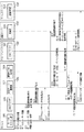
図1を用いて、本発明の実施形態に係る情報処理システム107を構成するデバイス105とクラウドシステム106、さらに情報処理システム107に接続するクライアントデバイス102について説明する。図1では、WAN(Wide Area Network)100を経由してクライアントデバイス102が、情報処理システム107を構築するサーバーコンピューター群とデバイス105とを接続している状態が示されている。WAN 100はLAN(Local Area Network)101によって各デバイスと接続されている。
The
クライアントデバイス102はPCやスマードフォン、タブレット、画像形成装置等の情報処理装置である。認証サーバー103は、クラウドユーザーやローカルユーザー等のユーザーや、MFP等のデバイス105を認証し、その認証情報を登録する。
The
サービスサーバー104は、WAN100を経由してクライアントデバイス102とデバイス105と通信可能であり、Message Queuing Telemetry Transport (MQTT) Brokerによるメッセージ通信を行うサーバー等が挙げられる。MQTTとはpublish/subscribeモデルのメッセージ通信プロトコルである。publish/subscribeモデルは、メッセージ送信者(以下、publisher)からメッセージ受信者(以下、subscriber)に対して、メッセージ仲介者であるMQTT brokerを介してメッセージを配信する。実施例では、サービスサーバー104がMQTT brokerの機能を有するものとして説明する。subscriberは、メッセージの送信先(以下、トピック)としてsubscriber自身を指定してメッセージをサービスサーバー104に送信し、そのトピックと一致したメッセージをサービスサーバー104から受信できるように予約する(以下、subscribe)。subscribeするためにsubscriberがサービスサーバー104に送信するメッセージをsubscribeメッセージと呼ぶ。
The
publisherは、サービスサーバー104に対してトピックを指定したメッセージを送信する。サービスサーバー104は、そのトピックと同じトピックをsubscribeしているsubscriberに対してメッセージを配信する(以下、publish)。publisherがpublishするためにトピックを指定してサービスサーバー104に送信するメッセージ、およびsubscriberに送信されるメッセージを、publishメッセージを呼ぶ。
The publisher sends a topic-specified message to the
トピックは「/」で区切られた階層構造(例:/A/BC/D/E)になっており、トピックの完全一致または一部一致をsubscriber側で指定することで、指定した条件に合ったトピックのメッセージをsubscriberが受信できる。MQTT brokerは、受信したpublishメッセージのトピックとsubscribeメッセージのトピックとの一致不一致を確認しており、一致した場合はpublishメッセージをsubscriberに送信する。これにより、ファイヤーウォールでサービスサーバー104からデバイス105への通信が遮断されていても、MQTTを用いることでデバイス105への通信が可能となる。
Topics have a hierarchical structure separated by "/" (example: / A / BC / D / E), and by specifying an exact match or a partial match on the subscriber side, the specified conditions are met. The subscriber can receive the message of the topic. The MQTT breaker confirms the match / mismatch between the topic of the received public message and the topic of the subscribing message, and if they match, sends the public message to the subscriber. As a result, even if the communication from the
後述の実施例は、サービスサーバー104がMQTT brokerの機能を有するものとして説明するが、デバイス105がサービスサーバー104からリクエストを取得できれば、他のプロトコルを用いた形態でもよい。例えば、デバイス105がサービスサーバー104に対して定期的に情報取得のためのリクエストを行い、そのレスポンスでサービスサーバー104からのリクエストを受信する形態も考えられる。
In the examples described later, the
さらに、サービスサーバー104はクライアントデバイス102に対して、設定変更サービス等のサービスを提供する。設定変更サービスでは、デバイス105における設定変更を受け付けるための画面やクラウドユーザーが要求した設定変更結果を確認する画面をクライアントデバイス102に提供する。クライアントデバイス102上でのユーザー操作に従って発行される設定変更のリクエストは、サービスサーバー104を経由してデバイス105に届く。また、サービスサーバー104は、設定変更サービスを提供するための機能呼び出し制御サービスも提供する。機能呼び出し制御サービスでは、設定変更サービスを提供するためにクライアントデバイス102から要求されたリクエストの受付やデバイス105から受信した実行結果を、指示したクラウドユーザーにのみ表示させるための制御を行う。後述の実施例では、サービスサーバー104がデバイス105の設定変更サービスを提供する例で説明するが、印刷サービスなどの他のサービスでも良く、また印刷サービスと設定変更サービスなどの複数のサービスを提供する形態であっても良い。
Further, the
デバイス105は、画像形成装置、PC、スマートフォン等の情報処理装置であり、複数のローカルユーザーに関する情報を管理する機能を有するデバイスである。デバイス105は、MQTT Brokerであるサービスサーバー104に対してトピックを指定したsubscribeメッセージを送信することで、そのトピックと一致したpublishメッセージを受信することができる。
The
また、本発明の認証サーバー103やサービスサーバー104等の各サーバーコンピューターは複数台で構成されていてもよく、または、ひとつのコンピューターサーバーが認証サーバー103やサービスサーバー104の機能を兼ね備えていても良い。例えば、サービスサーバー104は、MQTT Brokerと機能呼び出し制御サービスを提供する機能呼び出し制御サーバーとに分割することもできる。
Further, each server computer such as the
図2は、図1に示したクラウドシステム106を構成するサーバーコンピューターである情報処理装置200の内部構成について示したブロック図である。なお、図2に示されるブロック図は、クライアントデバイス102およびデバイス105も情報処理装置200と同様の内部構造を有しているものとする。
FIG. 2 is a block diagram showing an internal configuration of an information processing device 200 which is a server computer constituting the cloud system 106 shown in FIG. In the block diagram shown in FIG. 2, it is assumed that the
情報処理装置200において、CPU202、ROM203、RAM204、HDD205が内部バス201を介して接続されている。CPU202は、ROM203のブートプログラムを実行してHDD205に記憶されているOSや制御プログラムをRAM204に展開し、そのプログラムに基づいて、情報処理装置200の制御を行うユニットである。
In the information processing apparatus 200, the
ROM203は、情報処理装置200のブートプログラムや各種データ等が格納されている記憶装置である。
The
RAM204は、CPU202が命令を実行する際に使用するワークメモリである。ROM203に保存されていたプログラムがRAM204へとロードされ、そのプログラムの命令をCPU202が順次読みだし命令を実行する。
The
HDD205は外部記憶装置であり、OSや各種プログラムを格納している。
The
ネットワークI/F206は、内部バス201を介してCPU202、ROM203、RAM204、HDD205と接続されており、LAN100等のネットワークを介して情報処理装置200への情報の入出力を行う。
The network I /
尚、後述の全ての説明においては、特に断りのない限りコンピューターサーバーやデバイス等のハード上の主体はCPU202であり、ソフトウェア上の主体はHDD205にインストールされたアプリケーションプログラムである。
In all the explanations described later, unless otherwise specified, the main body on the hardware such as a computer server and the device is the
図3を用いて、クライアントデバイス102と認証サーバー103、サービスサーバー104、デバイス105が有する機能について説明する。クライアントデバイス102が有するWebブラウザ300を含め、本実施例における情報処理システム107内の装置が有する機能は、各装置のCPU202がRAM204にロードされたアプリケーションプログラムを実行することで実現される。機能の中でも特に、認証サーバー103やサービスサーバー104等のサーバーコンピューター上で実現される機能または機能群のことをクラウドサービスという。
The functions of the
クライアントデバイス102はWebブラウザ300を備え、Webブラウザ300は認証サーバー103やサービスサーバー104との通信を行う。Webブラウザ300は、WWW(World Wide Web)を利用するためのユーザーエージェントによって実現する機能であり、後述のWebブラウザ305も同様の機能である。
The
認証サーバー103は通信部301と認証部302とを備える。認証部302は、通信部301を介してクライアントデバイス102やサービスサーバー104、デバイス105との通信を行う機能である。
The
サービスサーバー104は通信制御部303と設定管理部304とを備える。通信制御部303は、MQTTにおけるsubscribeメッセージの受信やpublishメッセージの送信を行う機能である。また、設定管理部304は通信制御部303を介して、クライアントデバイス102の設定画面を介した要求の受付や、クライアントデバイス102で実行結果画面を表示するための設定情報を管理する機能である。
The
デバイス105は、Webブラウザ305とローカルログイン部306、認証サーバー連携部307、機能呼び出し制御部308とを備える。Webブラウザ305は、認証サーバー103やサービスサーバー104と通信を行う機能である。ローカルログイン部306は、デバイス105の利用者であるローカルユーザーを認証するための機能である。なお、このローカルログイン部306は、不図示の認証サーバーと通信することでローカルユーザーを認証するように構成することもできる。
The
認証サーバー連携部307は認証連携情報の発行要求を行う。また、クラウドシステム106の利用者であるクラウドユーザーを一意に識別するための情報であるクラウドユーザー認証情報と、ローカルユーザーを一意に識別するための情報であるローカルユーザー認証情報とを紐付ける機能でもある。
The authentication
認証連携情報とはクラウドユーザー認証情報とローカルユーザー認証情報とを紐付けるために用いられる認証情報である。認証連携情報の一例として、パスコード等が挙げられる。クラウドユーザー認証情報は、クラウドユーザーがクラウドシステム106にログインした時に生成される認証情報の総称であり、クラウドユーザーIDやクラウドユーザーUUID(Universally Unique Identifier)等のクラウドユーザーを一意に識別するための情報が含まれる。UUIDとはユーザーを一意に識別するための識別子であり、IDとは違って他のユーザーと重複しないことを前提に作られているものである。つまり、クラウドユーザーUUIDを用いることで、マルチテナントシステムにおいてテナントごとに設定されたユーザー情報も全て識別できるものとする。後述の例ではクラウドユーザー認証情報としてトークンの形態を用いて説明しているが、クラウドユーザーを識別できる情報であればどのような形態でもよい。一方、ローカルユーザー認証情報とは、ローカルユーザーがデバイス105にログインした時に生成される認証情報の総称であり、ローカルユーザーIDやローカルユーザーUUID等のローカルユーザーを一意に識別するための情報が含まれる。後述の例では、ローカルユーザー認証情報としてトークンの形態を用いて説明しているが、ローカルユーザーを識別できる情報であればどのような形態でもよい。後述では、認証連携情報を用いてクラウドユーザーUUIDとローカルユーザーUUIDとを紐付けた紐付け情報を例に説明する。
The authentication linkage information is the authentication information used for associating the cloud user authentication information with the local user authentication information. An example of authentication cooperation information is a passcode or the like. Cloud user authentication information is a general term for authentication information generated when a cloud user logs in to the cloud system 106, and is information for uniquely identifying a cloud user such as a cloud user ID or a cloud user UUID (Universally UUID). Is included. The UUID is an identifier for uniquely identifying a user, and unlike an ID, it is created on the premise that it does not overlap with other users. That is, by using the cloud user UUID, all the user information set for each tenant in the multi-tenant system can be identified. In the example described later, the form of the token is used as the cloud user authentication information, but any form can be used as long as the information can identify the cloud user. On the other hand, the local user authentication information is a general term for authentication information generated when a local user logs in to the
機能呼び出し制御部308は、クラウドユーザーUUIDとローカルユーザーUUIDとを紐付けるユーザー紐付け処理において、subscribeメッセージをサービスサーバー104に送信し、サービスサーバー104からの処理要求を待つ。
The function
図4を用いて、認証サーバー103がデバイス105を認証する過程を説明する。この過程は、デバイス105において認証サーバー連携部307がインストールされ、初めて認証サーバー連携部307が起動したタイミングで開始されるものとする。認証サーバー103の通信部301はデバイス105の認証が必要になるように構成されている。
The process in which the
S1.1にて、認証サーバー連携部307が通信部301に対してデバイス登録要求を送信する。認証サーバー連携部307からデバイス登録要求を受信した通信部301は、SSL/TLS通信のネゴシエーションを開始する。その際、通信部301は認証サーバー連携部307に対してデバイス認証情報を要求して受信する。デバイス認証情報とは、デバイス105を特定するためにSSL/TLS通信に用いられる証明書である。S1.2において、通信部301は不図示の証明書ストアにて設定されている証明書を用いて、S1.1で取得したデバイス認証情報を検証し、認証サーバー連携部307をデバイス105の登録要求元として認証する。S1.3にて、通信部301が認証部302に対して、認証サーバー連携部307から受信したデバイス登録要求とデバイス認証情報とを送信する。S1.4において認証部302は、S1.3で取得したデバイス認証情報を基に、デバイス105を一意に識別するためのデバイス識別情報を発行する。以降の実施例では、デバイス識別情報は証明書の形態を持つものとして説明するが、認証部302がデバイス105を一意に識別できさえすれば、デバイス識別情報は証明書の形態や数値文字列の形態などでも良い。S1.5にて、認証部302は通信部301を介して認証サーバー連携部307に対して、デバイス登録要求に対する応答としてデバイス識別情報を送信する。
In S1.1, the authentication
以上が、認証サーバー103がデバイス105を認証する過程である。この過程により、認証部302が発行したデバイス識別情報を用いることで、認証サーバー連携部307はデバイス105を特定することが可能となる。また、本実施例の事前設定は、認証サーバー連携部307を認証部302への登録する登録処理としているが、その処理には必ずしも限定されない。例えば、認証部302が発行したデバイス識別情報を認証サーバー連携部307へ手動で登録しても良い。また、出荷時に認証サーバー連携部307へ埋め込まれているデバイス認証情報をそのまま利用しても良い。また、以降の実施例では、「外部から通信部301を介して認証部302への通信」を、「外部から認証部302への通信」と記載する。
The above is the process in which the
[実施例1]
デバイス105がマルチユーザーデバイスである場合、ローカルユーザーUUIDに対して複数のクラウドユーザーUUIDの紐付けを許容する。実行結果がどのクラウドユーザーUUIDに対するものなのかをクラウドシステム106で特定し、リクエストとレスポンスとを紐付ける形態を実施例1で説明する。デバイス105の登録処理が成された状態(図4)で、認証部302が管理するクラウドユーザーUUIDとローカルログイン部306が管理するローカルユーザーUUIDとを紐付けるための認証連携情報を発行する過程を図5で説明する。
[Example 1]
When the
S2.1においてローカルログイン部306は、ローカルログイン部306において定められている認証方法によってユーザーのログイン処理を受信する。認証方法としては例えば、ユーザーIDとパスワードとの組み合わせを検証する方法、指紋等の生体情報を検証する方法、非接触型のICカードを利用する方法、更には複数の認証方法を組み合わせる多要素認証方法等が考えられる。また、不図示の認証サーバーと通信することでユーザーを認証するように構成することもできる。実施例1では、ローカルユーザーIDとパスワードとの組み合わせを検証する認証方法を用いた場合を例として説明する。表1は、ローカルログイン部306が管理するユーザー情報の一例である。
In S2.1, the

S2.2にて、ローカルログイン部306はローカルユーザーIDとパスワードの組を用いてローカルユーザー認証を行う。具体的には、ローカルログイン部306は表1のユーザー情報を参照してローカルユーザー認証を行う。例えば、ユーザーがローカルユーザーID「admin」とパスワード「admin」を入力した場合、ローカルログイン部306はローカルユーザーID「admin」のローカルユーザーとしてユーザーを認証する。
In S2.2, the
S2.3でローカルログイン部306は、S2.2で認証されたユーザーのローカルユーザー認証情報を生成し保存する。このローカルユーザー認証情報は、ユーザーが不図示のログアウト操作を実施するか、設定された時刻が経過するまで有力な状態で保存される。ローカルユーザー認証情報には、認証したユーザーのローカルユーザーID、ローカルユーザーUUID及び権限情報等が格納されている。つまり、表1で示したユーザー情報とほとんど同じ情報をローカルユーザー認証情報は含む。なお、ローカルログイン部306がローカルユーザー認証情報を直接格納する形態に限らない。ローカルユーザー認証情報と紐付けられたトークンをローカルログイン部306が格納し、そのトークンを参照することでローカルログイン部306とは別の場所に格納されたローカルユーザー認証情報を用いる形態でもよい。
In S2.3, the
S2.4において、Webブラウザ305はユーザーの操作により認証連携情報の発行要求を受け付ける。受信した発行要求に応じて、Webブラウザ305は認証サーバー連携部307に対して認証連携情報の発行要求を送信する(S2.5)。S2.6で認証サーバー連携部307はローカルログイン部306に対してローカルユーザーUUIDの取得要求を行う。S2.6の要求に対して、ローカルログイン部306は認証サーバー連携部307にローカルユーザーUUIDを応答する(S2.7)。S2.8にて、認証サーバー連携部307は認証部302に認証連携情報の発行要求を送信する。その際、S2.7で受信したローカルユーザーUUIDとS1.5で受信したデバイス識別情報とを認証部302に送信する。
In S2.4, the
S2.9で認証部302は認証連携情報を発行する。発行した認証連携情報とその有効期限の一例を表2に示す。実施例1では認証連携情報を文字列としているが、後述するようにQRコード(登録商標)などの形態の情報であっても構わない。また、実施例1では認証連携情報に有効期限が定められているが、無期限の認証連携情報でも良い。
In S2.9, the
S2.10において、認証部302はS2.9で発行された認証連携情報とS2.8で受信したローカルユーザーUUID及びデバイス識別情報とを紐付けた紐付け情報を管理する。紐付け情報の例を表3に示す。
In S2.10, the
S2.11にて、認証部302が認証サーバー連携部307に対して認証連携情報を応答する。認証サーバー連携部307は、ローカルユーザーUUIDとS2.11で受信した認証連携情報とを紐付ける(S2.12)。その際に生成されるマッピングテーブルの例を表4に示す。
In S2.11, the
S2.13において、S2.5における認証連携情報の発行要求に対して応答する。具体的には、S2.11で応答された認証連携情報をWebブラウザ305に送信し、Webブラウザ305は認証連携情報を表示する。これにより、ユーザーは認証連携情報を入手できる。S2.14で、subscribeメッセージの送信を依頼する。具体的には、後述するユーザー紐付け処理のために、認証サーバー連携部307は機能呼び出し制御部308に対して、通信制御部303へのsubscribeメッセージの送信を依頼する。S2.15にて、機能呼び出し制御部308が通信制御部303に対してsubscribeメッセージを送信する。subscribeメッセージのトピックは、デバイス識別情報で指定する。具体的には、トピックは「/」で区切られた階層構造(例:/A/BC/D/E)となっており、subscriberが受信したい情報の分類を定義できるので、「(デバイス105が設置されている場所)/(デバイス識別情報)」というように、メッセージの送信先を指定する。これによりデバイス105のデバイス識別情報をトピックとするpublishメッセージを、機能呼び出し制御部308が受信することができる。また、機能呼び出し制御部308は通信制御部303との通信を維持するために、通信の切断を検知する度に通信制御部303対してsubscribeメッセージを送信する。
In S2.13, it responds to the request for issuing the authentication cooperation information in S2.5. Specifically, the authentication cooperation information returned in S2.11 is transmitted to the
以上が認証連携情報を発行する過程である。これにより、認証サーバー103とデバイス105は、認証連携情報を用いたマッピングテーブル(表3、表4)を所有できる。また、ユーザーも認証連携情報を入手できる。
The above is the process of issuing authentication cooperation information. As a result, the
次に、認証サーバー103においてローカルユーザーUUIDとクラウドユーザーUUIDとを紐付けるユーザー紐付け処理について、図6を用いて説明する。S3.1でWebブラウザ300はユーザーからログイン操作を受け付け、S3.2でWebブラウザ300は認証部302に対してログイン処理を要求する。このログイン処理は認証部302において定められている認証方法によって行われる。認証方法としては例えば、ユーザーIDとパスワードの組み合わせを検証する方法を利用する方法等がある。実施例1では、クラウドユーザーIDとパスワードの組み合わせを例として説明する。表5に認証部302が管理するユーザー情報の一例を示す。
Next, the user associating process for associating the local user UUID and the cloud user UUID on the
S3.3において認証部302はクラウドユーザー認証を行い、S3.4で認証したクラウドユーザーのクラウドユーザー認証情報を生成し保存する。クラウドユーザー認証情報は、ユーザーが不図示のログアウト操作を実施するか、設定された時刻が経過するまで有力な状態で保存される。クラウドユーザー認証情報には、認証したクラウドユーザーのクラウドユーザーID、クラウドユーザーUUIDが格納されている。つまり、表5で示したユーザー情報とほとんど同じ情報をクラウドユーザー認証情報は含む。なお、認証部302が各認証情報を直接格納する形態のみならず、各認証情報が参照可能に紐付けられたトークンを認証部302が格納し、そのトークンを参照することで認証部302とは別の場所に格納された認証情報を用いるようにした形態でもよい。
In S3.3, the
S3.5において、認証部302がWebブラウザ300にログイン処理に対する応答を行う。その際、S3.4において生成されたクラウドユーザーUUIDと紐付くセッションIDがWebブラウザ300に送信される。セッションIDとは、ログインしたユーザーを識別するための識別子であり、本実施例ではS3.4において生成されたクラウドユーザーUUIDと紐付いて認証部302で管理されている。S3.5においてセッションIDをWebブラウザ300が受信することで、Webブラウザ300のCookie(不図示)にセッションIDが管理される。後述の実施例では特に断りがない限り、Webブラウザ300と認証部302における通信では、このセッションIDの受送信が行われる。
In S3.5, the
S3.6で、Webブラウザ300は認証連携情報の入力要求をユーザーから受信し、S3.7でWebブラウザ300は認証部302に対して認証連携情報の入力要求を行う。認証部302はWebブラウザ300からの認証連携情報入力要求に対して入力画面を応答する(S3.8)。S3.9にてWebブラウザ300はユーザーによる認証連携情報の入力操作を受け付け、S3.10において、受け付けた認証連携情報を認証部302に送信し、認証連携情報を用いた紐付け処理を要求する。S3.11において、S3.10で受信した認証連携情報と認証部302が管理しているクラウドユーザーUUIDとを紐付ける。具体的には、認証部302が管理しているクラウドユーザーUUIDと、S3.10で受信したセッションIDとを照合し、そのセッションIDを介してクラウドユーザーUUIDと認証連携情報とを紐付ける。その際に生成される紐付け情報の例を表6に示す。
In S3.6, the
S3.12において認証部302は、S2.10で作成したマッピングテーブル(表3)とS3.11で作成したマッピングテーブル(表6)とを一つのマッピングテーブルにまとめ、ローカルユーザーUUIDとクラウドユーザーUUIDとを紐付ける。具体的には、表3と表6とが共通の認証連携情報を有するのでその認証連携情報を介して、ローカルユーザーUUIDとクラウドユーザーUUIDとを紐付ける。その際のマッピングテーブルの例を表7に示す。表7の紐付け情報には、S3.10で受信したセッションIDも紐付いているものとする。
In S3.12, the
以上が、認証サーバー103においてローカルユーザーUUIDとクラウドユーザーUUIDとが紐付けるユーザー紐付け処理である。また、表7のようなマッピングテーブルを作成する際に認証連携情報が有効期限を迎え無効化されていれば、マッピングテーブル作成に失敗し、このユーザー紐付け処理を終了する。この際、マッピングテーブル作成に失敗した旨をWebブラウザ300に通知しても良い。
The above is the user linking process in which the local user UUID and the cloud user UUID are linked on the
次に、デバイス105においてローカルユーザーUUIDとクラウドユーザーUUIDとを紐付けるユーザー紐付け処理について、図7を用いて説明する。S4.1において、クラウドユーザーUUIDの紐付け依頼を送信する。具体的には、認証部302は通信制御部303に対して、S3.9で入力された認証連携情報とともにpublishメッセージを送信する。publishメッセージを送信する際のトピックはデバイス識別情報とする。これにより、S2.15で機能呼び出し制御部308が送信したsubscribeメッセージ(トピックはデバイス105のデバイス識別情報)と同じトピックのpublishメッセージを送信することができる。認証部302が送るメッセージは、通信制御部303がMQTTと他のプロトコルとの変換機能を備えていれば、MQTTのpublishメッセージでなくても構わない。
Next, the user associating process for associating the local user UUID and the cloud user UUID on the
S4.2において、クラウドユーザーUUIDの紐付け依頼を送信する。具体的には、subscribeメッセージを送信した機能呼び出し制御部308に対して、クラウドユーザーUUIDの紐付け依頼としてpublishメッセージを送る。その際、クラウドユーザーUUIDと認証連携情報も送信される。subscribeメッセージは、S4.1で受信したpublishメッセージと同じトピックなので、機能呼び出し制御部308にpublish メッセージが送信される。S4.3にて、機能呼び出し制御部308が認証サーバー連携部307に対して、クラウドユーザーUUIDの紐付け要求を行う。その際、S4.2で受信した認証連携情報とクラウドユーザーUUIDも同時に通知する。S4.4では、認証サーバー連携部307が、S4.3で受信したクラウドユーザーUUIDと認証連携情報とを用いて、ローカルユーザーUUIDとクラウドユーザーUUIDとの紐付け処理を行う。認証サーバー連携部307では、S2.12においてローカルユーザーUUIDと認証連携情報とが紐付けているため、認証連携情報を介してローカルユーザーUUIDとクラウドユーザーUUIDとを紐付けることができる。S4.4において生成されるマッピングテーブルの例を表8に示す。
In S4.2, the cloud user UUID association request is transmitted. Specifically, a public message is sent to the function
以上が、デバイス105におけるローカルユーザーUUIDとクラウドユーザーUUIDとを紐付けるユーザー紐付け処理である。図6のユーザー紐付け処理により認証サーバー103ではローカルユーザーUUIDとクラウドユーザーUUIDとが紐づき、図7のユーザー紐付け処理によりデバイス105ではローカルユーザーUUIDとクラウドユーザーUUIDとが紐付いた。
The above is the user linking process for linking the local user UUID and the cloud user UUID on the
次にデバイス105における機能呼び出し処理を、図8を用いて説明する。今回は、デバイス105の設定を例に機能呼び出し処理を説明するが、設定要求以外にもデバイス105の機能を利用するための実行要求なども考えられる。実施例1において、既に説明しているステップと同じステップには同じ符番をふり、詳細な説明は省略する。他の実施例の場合も同様である。
Next, the function call process in the
S5.1において、Webブラウザ300はユーザーから設定画面の要求を受信する。このとき、デバイス識別情報も同時に受信する。S5.2でWebブラウザ300は設定管理部304に設定画面を要求し、S5.3で設定管理部304はそれに対して応答する。今回、Webブラウザ300とサービスサーバー104間のメッセージ通信プロトコルがHTTP(Hypertext Transfer Protocol)だとすると、S5.2でWebブラウザ300から送信される設定要求は、HTTPの方式に従ったリクエストメッセージである。以降のWebブラウザ300とサービスサーバー104間のやり取りも同様である。設定管理部304が応答した設定画面の例を図9に示す。図9の設定画面はデバイス識別情報と、設定項目テーブル、入力完了ボタンを保有する。設定項目テーブルにおいて、設定値列に新しく設定したい設定値を入力する。さらに、ユーザーの操作により設定画面上の入力完了ボタンが押下されると、後述のS5.5のステップが開始される。
In S5.1, the
S5.4においてWebブラウザ300はユーザーから設定情報入力操作を受信する。具体的には、Webブラウザ300は表示している設定画面(図9)において設定情報の入力操作を受信し、「入力完了」ボタンが押下される。その際、「オートスリープ移行時間」の「設定値」欄に「5分」とユーザーが入力し、その設定情報をWebブラウザ300が受信したものとする。オートスリープ移行時間とは、オートスリープ(起動中のデバイス105が消費電力を抑えるために一定時間ユーザーによる操作がなければ停止する)が起こるまでの時間のことをいう。S5.5で、Webブラウザ300は設定管理部304に設定要求を送信する。その際Webブラウザ300は、S3.5で受信したセッションIDを設定管理部304に対して送信する。具体的には、オートスリープ移行時間を5分にするための設定要求が設定管理部304に送信される。
In S5.4, the
S5.6において設定管理部304が通信制御部303に対して、Webブラウザ300から受信した設定要求を送信する。その際、S5.1においてユーザーによって指定されたデバイス識別情報も送信される。S5.7において、通信制御部303は認証部302に対してローカルユーザーUUIDの取得要求を行う。その際、ローカルユーザーUUIDの取得要求とともにセッションIDが認証部302に送信される。認証部302において紐付いているローカルユーザーUUIDとクラウドユーザーUUIDとセッションIDとの紐付け情報(表7)を用いて、通信制御部303から受信したセッションIDと紐付くローカルユーザーUUIDを特定し、通信制御部303からの取得要求に対して送信すべきローカルユーザーUUIDを特定することができる。S5.8において、認証部302が通信制御部303に対してローカルユーザーUUIDを送信することで、ローカルユーザーUUIDの取得応答を行う。
In S5.6, the
S5.9において、通信制御部303が、S5.8で取得したローカルユーザーUUIDとS5.6で受信した設定要求とを機能呼び出し制御部308に対して送信する。具体的には、オートスリープ移行時間を5分にするための設定要求が機能呼び出し制御部308に送信される。実施例1では、サービスサーバー104がMQTTによるメッセージ通信を行うサーバーである場合を例に説明しているので、設定要求を機能呼び出し制御部308にpublishメッセージを送信する。その際のトピックはデバイス識別情報である。これにより、S2.15で機能呼び出し制御部308が送信したsubscribeメッセージ(トピックはデバイス105のデバイス識別情報)と同じトピックのpublishメッセージを送信することができる。
In S5.9, the
S5.10において機能呼び出し制御部308は、S5.9で受信したpublishメッセージの内容に応じて設定要求を実行する。その際、設定要求とともに受信したローカルユーザーUUIDで特定されるローカルユーザーとして設定要求を実行する。具体的には、機能呼び出し制御部308がローカルユーザーUUID「AAA1」を受信した場合、デバイス105が保有するユーザー情報(表1)より、ローカルユーザーID「admin」としてオートスリープ移行時間が5分に設定される。
In S5.10, the function
S5.11において、通信制御部303から受信したローカルユーザーUUIDと紐づくクラウドユーザーUUIDの取得要求を、機能呼び出し制御部308が認証サーバー連携部307に対して行う。S5.12において、認証サーバー連携部307が管理しているマッピングテーブル(表8)を用いて、ローカルユーザーUUIDと紐づくクラウドユーザーUUIDを機能呼び出し制御部308に応答する。S5.13において機能呼び出し制御部308は、S5.12で取得したクラウドユーザーUUIDとともに実行結果を通信制御部303に対して応答する。ここで、実行結果とともにクラウドユーザーUUIDを送信する理由は、通信制御部303において1つのローカルユーザーUUIDに対し複数のクラウドユーザーUUIDが紐付いている場合があるため、通信制御部303において一意に特定されるクラウドユーザーUUIDを送信する必要がある。
In S5.11, the function
実施例1では設定要求として、「オートスリープ移行時間を5分」にするデバイス105の設定変更をWebブラウザ300から受信した例として説明しているため、S5.13における実行結果の応答には設定変更後の値が含まれる。デバイス105がMFP等の印刷機能を有している場合、設定要求としては印刷機能の利用なども考えられる。その場合は結果応答としてステータス情報を通信制御部303に送信するなど、設定要求の内容に応じて実行結果の応答に含まれる情報は変わる。また、デバイス105の設定が失敗したときや機能の実行が失敗したときは、応答される実行結果にはエラーに関する情報が含まれる。
In the first embodiment, as a setting request, the setting change of the
S5.14において、通信制御部303は設定管理部304に対してクラウドユーザーUUIDとともに設定要求の実行結果を送信する。設定管理部304はS5.14で受信したクラウドユーザーUUIDを用いることで、どのクラウドユーザーによる設定要求に対して結果が応答されたのかを特定することができる。また、設定管理部304が認証部302から、クラウドユーザーUUIDと紐付くローカルユーザーUUIDを取得することで、どのローカルユーザーによる設定要求に対して結果が応答されたのかも特定することができる。実行結果とそれを実行した際に用いたローカルユーザーUUIDとクラウドユーザーUUIDは、最終的には設定管理部304で管理される。
In S5.14, the
以上が、デバイス105における機能呼び出し処理である。これにより、ユーザーはクライアントデバイス102のWebブラウザ300を介して、デバイス105が公開している機能を利用することができ、その機能を利用したことによる実行結果を確認することができる。
The above is the function call process in the
デバイス105の機能を実行した後、クライアントデバイス102のWebブラウザ300は不図示の実行結果画面の要求をユーザーから受信し、実行結果画面を表示することができる。その実行結果画面の例を図10に示す。図10には、設定変更を行ったデバイス105のデバイス識別情報とその設定変更の前後の値が格納されている。また、各設定項目に対して設定変更ステータスを格納することも可能である。
After executing the function of the
また、その実行結果画面を表示するための、結果取得処理のフローの一例を図12に示す。本フローの起動は、ユーザーが実行結果画面を要求したときである。その際、実行結果を要求するデバイス105のデバイス識別情報とレスポンス識別情報とが、Webブラウザ300において選択される。選択する際にWebブラウザ300に表示される実行結果選択画面の一例を図11に示す。図11では「内容概要」の欄内の各項目に対してリンクがあり、そのリンクが選択されることでレスポンス識別情報が選択され、実行結果画面が要求される。また、実施例1ではリクエストとレスポンスが直接紐付くわけではないため、図11ではリクエストとレスポンスを分割して記載しているが、この形態に限定されるわけではない。実行結果選択画面上でクラウドユーザーの実行履歴を管理することも可能である。図11の画面でデバイス識別情報とレスポンス識別情報が選択された後、S6.1で設定管理部304が認証部302から、ログインしているクラウドユーザーのクラウドユーザーUUIDを取得する。S6.2にて、設定管理部304はS6.1で取得したクラウドユーザーUUIDと、選択されたデバイス識別情報とレスポンス識別情報を用いて、デバイス105の実行結果に関する情報を格納する不図示のデータベースから取得する。
Further, FIG. 12 shows an example of the flow of the result acquisition process for displaying the execution result screen. This flow is started when the user requests the execution result screen. At that time, the device identification information and the response identification information of the
以上が、実行結果画面を表示するための結果取得処理のフローである。これにより、ユーザーは自身が要求したリクエストに対するデバイス105の実行結果を参照することが可能となる。結果取得処理のフローは、図11や図12の形態に限らない。例えば、ユーザーは結果画面要求時にリクエストの選択を行わず、これまでの実行結果から最新の情報のみを閲覧するような形態等も考えられる。また、ユーザーの実行結果画面要求に応じて実行結果を取得するのではなく、S5.14で設定管理部304が実行結果を取得した際に実行結果画面を作成しておくことも考えられる。
The above is the flow of the result acquisition process for displaying the execution result screen. As a result, the user can refer to the execution result of the
[実施例2]
デバイス105が保有するローカルユーザーUUIDと認証サーバー103で保有するクラウドユーザーUUIDが漏洩することで、ユーザーのなりすましが行われる可能性がある。そのため、ユーザー紐付け処理において共通鍵を発行し、機能呼び出し処理において署名情報を付与することでデバイス105への設定要求の改竄を検知することができる。設定要求の改竄で例えば、デバイス105への設定要求が「オートスリープ移行時間を5分にする」ための設定要求だとすると、この設定要求が改竄されて「オートスリープ移行時間を1分にする」など、ユーザーが意図していない設定要求がデバイス105で実行されてしまう。実施例2では、共通鍵を利用した場合のユーザー紐付け処理と機能呼び出し処理について説明する。実施例1のユーザー紐付け処理(図6、図7)と、機能呼び出し処理(図8)とで同様のステップについては詳細な説明は省略する。
[Example 2]
By leaking the local user UUID held by the
まず、共通鍵を用いた場合の、認証サーバー103におけるローカルユーザーUUIDとクラウドユーザーUUIDとのユーザー紐付け処理について図6を用いて説明する。S3.11を後述のS7.1、S3.12を後述のS7.2に置き換えることで、共通鍵を用いた場合のユーザー紐付け処理が実現する。
First, the user association process between the local user UUID and the cloud user UUID on the
Webブラウザ300はユーザーから認証連携情報の入力要求を受信し(S3.6)、認証部302に対して認証連携情報の入力要求を行う(S3.7)。S3.7の入力要求に対して、認証部302は認証連携情報の入力画面を応答する(S3.8)。Webブラウザ300は、応答された入力画面を用いて認証連携情報の入力操作をユーザーから受け付け(S3.9)、認証部302に対して紐付け処理を要求する(S3.10)。S7.1において、認証部302でクラウドユーザーUUIDと認証連携情報との紐付け処理を行い、その紐付け情報に対して共通鍵を発行する。S7.1で発行された共通鍵を用いて、認証部302はクラウドユーザーUUIDとローカルユーザーUUIDとデバイス識別情報との紐付け情報(表7)と共通鍵とを紐付ける(S7.2)。
The
以上が、共通鍵を用いた場合の、認証サーバー103におけるローカルユーザーUUIDとクラウドユーザーUUIDとのユーザー紐付け処理である。これにより認証部302は、ローカルユーザーUUIDとクラウドユーザーUUIDと紐づいた共通鍵を保持できる。
The above is the user association process between the local user UUID and the cloud user UUID on the
次に、共通鍵を用いた場合の、デバイス105におけるローカルユーザーUUIDとクラウドUUIDとのユーザー紐付け処理について図13を用いて説明する。S7.3において、認証連携情報とクラウドユーザーUUIDと共通鍵の紐付け依頼を送信する。具体的には、認証部302がS3.9において入力された認証連携情報とS7.1において発行された共通鍵ともに通信制御部303に対してpublishメッセージを送信する。publishメッセージを送信する際のトピックはデバイス識別情報とする。これにより、S2.15において機能呼び出し制御部308が送信したsubscribeメッセージ(トピックはデバイス105のデバイス識別情報)と同じトピックのpublishメッセージを送信することができる。この際に認証部302が送るメッセージは、通信制御部303がMQTTと他のプロトコルとの変換機能を備えていれば、MQTTのpublishメッセージでなくても構わない。
Next, the user association process between the local user UUID and the cloud UUID on the
S7.4において、クラウドユーザーUUIDと共通鍵の紐付け依頼を送信する。今回は、subscribeメッセージを送信した機能呼び出し制御部308に対して、クラウドユーザーUUIDの紐付け依頼としてpublishメッセージを送る。そのメッセージとともに、クラウドユーザーUUIDと認証連携情報と共通鍵が送信される。subscribeメッセージには、S7.3で受信したpublishメッセージと同じトピックなので、機能呼び出し制御部308にpublishメッセージが送信される。S7.5にて、機能呼び出し制御部308は認証サーバー連携部307に対して、クラウドユーザーUUIDの紐付け要求を行う。その際、S7.4で受信した認証連携情報とクラウドユーザーUUID、共通鍵も同時に通知する。S7.6では、ローカルユーザーUUIDとクラウドユーザーUUIDと共通鍵とを紐付ける紐付け処理を行う。具体的には認証サーバー連携部307が、S4.3で受信したクラウドユーザーUUIDと認証連携情報と共通鍵とを用いて、紐付け処理を行う。
In S7.4, the cloud user UUID and the common key association request are transmitted. This time, a public message is sent to the function
以上が、共通鍵を用いた場合の、デバイス105におけるローカルユーザーUUIDとクラウドユーザーUUIDとのユーザー紐付け処理である。これにより認証サーバー連携部307は、ローカルユーザーUUIDとクラウドユーザーUUIDと紐づいた共通鍵を保持できる。
The above is the user association process between the local user UUID and the cloud user UUID on the
上記した内容では、対称鍵暗号の共通鍵基盤を前提として鍵交換を行った。しかしこれに限定されることはなく、例えば非対称鍵暗号の公開鍵基盤を用いても良い。その場合、S7.1において認証部302で非対称鍵ペア(公開鍵、秘密鍵)を発行し、S7.4において公開鍵を機能呼び出し制御部308に送信する。その後さらに、認証サーバー連携部307で非対称鍵ペアを発行し、その公開鍵を認証部302に送信することが考えられる。デバイス105が鍵発行機能を備えていない場合は、認証部302が代行して非対称鍵ペアを2ペア発行しても良い。
In the above contents, the key exchange was performed on the premise of the common key infrastructure of symmetric key cryptography. However, the present invention is not limited to this, and for example, a public key infrastructure of asymmetric key cryptography may be used. In that case, the
次に、共通鍵を用いた場合の機能呼び出し処理を図14で説明する。図8の機能呼び出し処理のときと同じステップには同じ符番をふり、詳細な説明は省略する。S5.1において、Webブラウザ300はユーザーからデバイス識別情報とともに設定画面要求操作を受信する。受信した設定画面要求操作に応じてWebブラウザ300は、設定管理部304に対して設定画面を要求し(S5.2)、設定管理部304は設定画面をWebブラウザ300に応答する(S5.3)。応答された設定画面の例は図9に示した通りである。Webブラウザ300はユーザーから設定情報入力操作を受信し(S5.4)、受信した設定要求を設定管理部304に送信する(S5.5)。今回も実施例1のときと同様に、「オートスリープ移行時間」の「設定値」欄に「5分」とユーザーが入力し、S5.4においてその設定要求をWebブラウザ300が受信したものとする。オートスリープ移行時間を5分にするための設定要求がWebブラウザ300から設定管理部304に送信される(S5.5)。設定管理部304は受信した設定要求を送信する(S5.6)。
Next, the function call process when the common key is used will be described with reference to FIG. The same number is assigned to the same step as in the function call process of FIG. 8, and detailed description thereof will be omitted. In S5.1, the
S7.7において、通信制御部303は認証部302にローカルユーザーUUIDと共通鍵の取得要求を行う。S7.1でクラウドユーザーUUIDと認証連携情報との紐付け情報に対して共通鍵が発行されているので、S7.7で通信制御部303が認証部302にセッションIDを送信することで、要求されている共通鍵を特定できる。具体的には、S7.2においてローカルユーザーUUIDとクラウドユーザーUUIDとセッションIDとの紐付け情報と共通鍵とが紐付いているので、通信制御部303から受信したセッションIDを用いて、要求されている共通鍵を特定する。S7.8において、認証部302が通信制御部303に対してローカルユーザーUUIDと共通鍵を送信する。その結果、サービスサーバー104において共通鍵とローカルユーザーUUIDとクラウドユーザーUUIDとが紐付く。S7.9において、共通鍵を用いて設定要求に対して署名情報を付与する。送信されるリクエストはJWT(JSON Web Token)形式の文字列として生成され、更にJWS(JSON Web Signature)で定義される署名情報が付与される。署名情報の形式は、必ずしもJWT、JWAに限定されるわけではない。後述の署名情報についても同様である。
In S7.7, the
S7.10において通信制御部303は機能呼び出し制御部308に、S7.8で取得したローカルユーザーUUIDとともにS7.9において署名情報を付与した設定要求をpublishメッセージとして送信する。その際のトピックはデバイス105のデバイス識別情報である。これにより、S2.15で機能呼び出し制御部308が送信したsubscribeメッセージ(トピックはデバイス105のデバイス識別情報)と同じトピックのpublishメッセージを送信することができる。設定要求の具体例として今回は、オートスリープ移行時間を5分にするための設定要求が機能呼び出し制御部308に送信される。
In S7.10, the
S7.11において、機能呼び出し制御部308は認証サーバー連携部307にクラウドユーザーUUIDと共通鍵の取得要求を行う。S7.11の取得要求に対して、認証サーバー連携部307はクラウドユーザーUUIDと共通鍵とを応答する(S7.12)。S7.6で、認証サーバー連携部307においてローカルユーザーUUIDとクラウドユーザーUUIDと共通鍵とが紐付けた。そのため、認証サーバー連携部307は、S7.12で機能呼び出し制御部308に応答すべきクラウドユーザーUUIDと共通鍵を特定することができる。
In S7.11, the function
S7.13において、機能呼び出し制御部308がS7.12において受信した共通鍵を用いて、設定要求に付与された署名情報を検証した後、S7.10で受信したpublishメッセージの内容に応じて、オートスリープ移行時間を5分にするための設定機能を実行する。S7.14において、機能呼び出し制御部308は通信制御部303に設定要求の実行結果を応答すると同時に、送信するメッセージに対して署名情報を付与する。S7.14において、機能呼び出し制御部308はS7.8において受信した共通鍵を用いて、実行結果に付与された署名情報を検証する。署名情報の検証後、通信制御部303は設定管理部304に対して、クラウドユーザーUUIDとともに設定要求の実行結果を送信する(S5.14)。
In S7.13, the function
以上が、共通鍵を用いた場合の機能呼び出し処理である。これにより、Webブラウザ300を介してデバイス105が公開している機能を利用でき、さらにデバイス105への設定要求の改竄検知を行うことができる。
The above is the function call processing when the common key is used. As a result, the function disclosed by the
[実施例3]
実施例1、2では、デバイス105がマルチユーザーデバイスである形態を説明した。実施例3では、デバイス105がシングルユーザーデバイスである形態を図15、図16を用いて説明する。ただし、マルチユーザーデバイスである場合と同じ過程については、同じステップの番号を用いて詳細の説明を省略する。ここで、シングルユーザーデバイスとは、デバイスの機能を用いる際にログイン操作を必要とせず、複数のローカルユーザーを管理する機能を有さないデバイスのことである。そのため、実施例1や実施例2とは異なり、実施例3でのデバイス105はローカルログイン部306を備えていない。
[Example 3]
In Examples 1 and 2, the embodiment in which the
図15を用いて、デバイス105がシングルユーザーデバイスの場合の認証連携情報を発行する過程を説明する。マルチユーザーデバイスの場合(図5)との相違点はデバイス105がローカルログイン部306を備えていないため、ログイン処理によりローカルユーザーを認証する過程(S2.1〜S2.3)が図15には存在しない。まず、S2.4においてWebブラウザ305が認証連携情報の発行要求を受信した後、S2.5で認証サーバー連携部307に認証連携情報の発行要求を送信する。
The process of issuing the authentication cooperation information when the
S8.1にて、認証サーバー連携部307が認証部302に対して認証連携情報の発行要求とともに、デバイス識別情報を送信する。S2.9で、認証部302は認証連携情報を発行する。発行された認証連携情報の一例は表2に示した通りである。S8.2において、認証部302が認証連携情報とデバイス識別情報との紐付け情報を管理する。S2.11にて、認証部302は認証サーバー連携部307に対して認証連携情報の応答を行う。S8.3において、認証サーバー連携部307はS2.11において受信した認証連携情報とデバイス識別情報とを紐づけて保存する。S2.13で、その認証連携情報をWebブラウザ305に応答し、ユーザーはWebブラウザ305を介して認証連携情報を入手する。S2.14で、後述のユーザー情報紐付け処理のために、認証サーバー連携部307が機能呼び出し制御部308に対して、通信制御部303へのsubscribeメッセージの送信を依頼する。S2.15で、機能呼び出し制御部308は通信制御部303に対して、subscribeメッセージを送信する。subscribeメッセージを送信する際のトピックはデバイス識別情報である。
In S8.1, the authentication
以上が、デバイス105がシングルユーザーデバイスの場合の認証連携情報を発行する過程となる。これにより、認証連携情報とデバイス識別情報とが紐づいた紐付け情報を認証部302と認証サーバー連携部307とで管理することができ、ユーザーは認証連携情報を入手することができる。
The above is the process of issuing the authentication cooperation information when the
デバイス105がシングルユーザーデバイスの場合の、認証サーバー103におけるユーザー情報紐付け処理について図6を用いて説明する。図6におけるS3.12を後述のS9.1に置き換えることで本処理は実現する。それ以外のステップについてはマルチユーザーデバイスの場合と同じなので、詳細な説明は省略する。
When the
Webブラウザ300はユーザーから認証連携情報の入力要求を受信し(S3.6)、認証連携情報の入力要求を認証部302に対して送信する(S3.7)。認証部302は受信した入力要求に対して、認証連携情報の入力画面をWebブラウザ300に応答する(S3.8)。Webブラウザ300はその入力画面を介して認証連携情報の入力操作をユーザーから受け付け(S3.9)、認証部302に対して紐付け処理の要求とともに、受け付けた認証連携情報を送信する(S3.10)。認証部302は受信した認証連携情報を用いてクラウドユーザーUUIDと認証連携情報との紐付け処理を行う(S3.11)。紐付け処理によって得られた紐付け情報の例は表6に示した通りである。
The
S9.1では、認証部302はクラウドユーザーUUIDとデバイス識別情報とが紐づいたマッピングテーブルを生成する。具体的には、S3.11で作成した紐付け情報と、S8.2で作成した紐付け情報とを用いて、認証連携情報を介してクラウドユーザーUUIDとデバイス識別情報とを紐付ける。以上がシングルユーザーデバイスの場合の、認証サーバー103におけるユーザー紐付け処理である。これにより、認証部302はクラウドユーザーUUIDとデバイス識別情報との紐付け情報を管理することができる。
In S9.1, the
次に、デバイス105がシングルユーザーデバイスの場合の、デバイス105におけるユーザー紐付け処理について図7を用いて説明する。図7のS4.4を後述のS9.2に置きかえることで本処理は実現する。それ以外のマルチユーザーデバイスの場合と同じステップに関しては、同じ符番をふり詳細な説明は省略する。
Next, when the
認証部302は通信制御部303に対してクラウドユーザーUUIDの紐付け依頼を送信する(S4.1)。通信制御部303は機能呼び出し制御部308に対してクラウドユーザーUUIDの紐付け依頼を送信する(S4.2)。機能呼び出し制御部308は認証サーバー連携部307に対して、クラウドユーザーUUIDの紐付け要求を送信する(S4.3)。その際、S4.2で受信した認証連携情報とクラウドユーザーUUIDも同時に通知する。S9.2において、クラウドユーザーUUIDとデバイス識別情報とを紐付けた紐付け情報を管理する。認証サーバー連携部307はデバイス識別情報と認証連携情報との紐付け情報を管理している(S8.3)ので、S9.2ではその紐付け情報とS4.3で受信した情報を用いて、クラウドユーザーUUIDとデバイス識別情報とを紐付けることができる。
The
以上が、シングルユーザーデバイスの場合の、デバイス105におけるユーザー紐付け処理である。これにより、認証サーバー連携部307において、デバイス識別情報とクラウドユーザーUUIDとの紐付け情報を管理することができる。また、本処理においても、デバイス105がマルチユーザーデバイスの場合と同様に、暗号鍵を用いることが可能である。この際、S9.2にて共通鍵を発行し、クラウドユーザーUUIDとデバイス識別情報との紐付け情報に対して紐付ける。
The above is the user association process in the
次にシングルユーザーデバイスの場合の機能呼び出し処理について、図16を用いて説明する。マルチユーザーデバイスの場合と同じステップに関しては、同じ符番をふり詳細な説明は省略する。まず、Webブラウザ300はユーザーからデバイス識別情報とともに設定画面要求操作を受信する(S5.1)。Webブラウザ300は設定管理部304に設定画面を要求し(S5.2)、設定管理部304はWebブラウザ300に対して応答する(S5.3)。その際の設定画面の例は図9に示した通りである。Webブラウザ300は設定情報入力操作をユーザーから受信し(S5.4)、設定要求を設定管理部304に送信する(S5.5)。設定管理部304は通信制御部303に対して設定要求を送信する(S5.6)。
Next, the function call process in the case of a single user device will be described with reference to FIG. For the same steps as in the case of a multi-user device, the same number is used and detailed explanation is omitted. First, the
S9.3において、通信制御部303は認証部302に対してクラウドユーザーUUIDの取得要求を行う。具体的には、S5.5においてWebブラウザ300が設定管理部304に送信したセッションIDを、設定管理部304が通信管理部303に送信することで、S9.3においてクラウドユーザーUUIDの取得要求とともにセッションIDが送信される。認証部302は、受信したセッションIDと紐付くクラウドユーザーUUIDを特定し、S9.4において通信制御部303にクラウドユーザーUUIDの取得応答を行う。
In S9.3, the
S9.5にて通信制御部303は機能呼び出し制御部308に対し、設定要求としてpublishメッセージを送信し、それと同時にクラウドユーザーUUIDを送信する。これにより、S2.15で機能呼び出し制御部308が送信したsubscribeメッセージ(トピックはデバイス識別情報)と同じトピックのpublishメッセージを送信することができる。S5.4において、オートスリープ移行時間を5分にするための設定要求をWebブラウザ300が受け付けたものとすると、S9.5で送信した設定要求は、オートスリープ移行時間を5分にするための設定要求である。
In S9.5, the
S9.6において、機能呼び出し制御部308はS5.9で受信したpublishメッセージの内容に応じて設定要求を実行する。その際、設定要求とともに受信したクラウドユーザーUUIDで特定されるクラウドユーザーとして設定要求を実行する。具体的には、機能呼び出し制御部308がクラウドユーザーUUID「CCC1」を受信した場合、クラウドユーザーID「se001」としてオートスリープ移行時間を5分にするための設定が実行される。
In S9.6, the function
S5.13において機能呼び出し制御部308は、S5.12で取得したクラウドユーザーUUIDとともに実行結果を通信制御部303に対して応答する。S5.14において、通信制御部303は設定管理部304に対してクラウドユーザーUUIDとともに実行結果を送信する。以上が、デバイス105がシングルユーザーデバイスである場合の機能呼び出し処理である。これにより、デバイス105がシングルユーザーデバイスの場合でも、ユーザーはクライアントデバイス102のWebブラウザ300を介して、デバイス105が公開している機能を利用することができ、その機能を利用したことによる実行結果を確認することができる。
In S5.13, the function
また、ユーザー情報紐付け処理において暗号鍵を用いて紐付けを行う場合についても説明する。その場合、S9.4において認証部302はクラウドユーザーUUIDと同時に共通鍵を取得する。S9.5において、リクエストするメッセージに取得した共通鍵を用いて署名情報を付与する。機能呼び出し制御部308が共通鍵を用いて署名情報を検証した後、S9.6で設定要求を実行する。
In addition, a case where linking is performed using an encryption key in the user information linking process will also be described. In that case, in S9.4, the
S5.13で実行結果を送信する前に、認証サーバー連携部307にS9.5で受信したクラウドユーザーUUIDと紐付く共通鍵を取得し、実行結果に署名情報を付与する。実行結果を受信した通信制御部303は、共通鍵を用いて実行結果に付与されている署名情報を検証する。検証後、S5.14において通信制御部303は設定管理部304に対してクラウドユーザーUUIDとともに実行結果を応答する。デバイス105がマルチユーザーデバイスである場合と同様に、共通鍵に限定されるわけではなく、例えば公開鍵でも同様に署名情報を付与できる。
Before transmitting the execution result in S5.13, the authentication
実施例3より、クラウドシステムを介してシングルユーザーデバイスの機能を実行する際に、その実行結果がどのクラウドユーザーUUIDに対するものなのかをクラウドシステム106で特定し、リクエストとレスポンスとを紐付けることができる。 From the third embodiment, when the function of the single user device is executed via the cloud system, the cloud system 106 can specify which cloud user UUID the execution result is for, and the request and the response can be linked. it can.
また、実施例1と実施例3より、デバイス105がシングルユーザーデバイスかマルチユーザーデバイスかによって、認証連携情報を発行する過程やユーザーUUIDの紐付け処理等のシーケンスが異なる。そのためには、デバイス105がマルチユーザーデバイスかシングルユーザーデバイスかを予め判定する必要がある。
Further, from the first embodiment and the third embodiment, the process of issuing the authentication linkage information and the sequence of the user UUID linking process are different depending on whether the
その判定方法の一つとして、デバイス105のデバイス識別情報を用いる方法がある。デバイス識別情報に予め、デバイス105を一意に識別する情報以外にも、デバイス105がシングルユーザーデバイスなのか、マルチユーザーデバイスなのかを示す情報が含まれている。その一例を表9に示す。
As one of the determination methods, there is a method of using the device identification information of the
表9では、デバイス識別情報の末尾の数字が「00」の場合はシングルユーザーデバイスであり、「01」の場合はマルチユーザーデバイスである例を示している。ただし、デバイス識別情報に、デバイス105に関する情報を含める形態は表9の形態に限らない。
In Table 9, when the number at the end of the device identification information is "00", it is a single user device, and when it is "01", it is a multi-user device. However, the form in which the device identification information includes the information about the
S1.3において、通信部301は認証部302にデバイス登録要求を送信すると同時に、認証サーバー連携部307から受信したデバイス識別情報を通知する。このデバイス識別情報(表9)により、デバイス105がマルチユーザーデバイスであるか否かを判定することができる。
In S1.3, the
判断方法の二つ目は、認証部302がテーブル(表10)を予め保持している方法である。認証部302には予め、デバイス105がシングルユーザーデバイスなのかマルチユーザーデバイスなのかを示す情報を管理するテーブルがあり、そのテーブルを参考にしてデバイス105の判定を行うことができる。そのテーブルの一例を表10に示す。
The second determination method is a method in which the
今回はデバイス識別情報として数字を例に説明したが、デバイス105を一意に識別する情報であれば何でもよい。また、デバイス105がマルチユーザーデバイスかシングルユーザーデバイスかの判定は、通信部301や認証部302、通信制御部303が実行してもよく、認証連携情報を発行する過程やユーザーUUIDの紐付け処理等のシーケンスが開始される前であれば、どのタイミングで行ってもよい。
This time, a number has been described as an example of the device identification information, but any information that uniquely identifies the
実施例3より、デバイス105がシングルユーザーデバイスの場合でも、ユーザーはクライアントデバイス102のクラウドシステム106を介して、デバイス105が公開している機能を利用することができ、その機能を利用したことによる実行結果を確認できる。さらに、デバイス105がマルチユーザーデバイスなのかどうかを判断することにより、実施例1と実施例3のどちらのシーケンスを実行すべきかを判断できる。
From the third embodiment, even when the
[実施形4]
実施例1では、ユーザーがデバイス105において認証連携情報を取得し、取得した認証連携情報をクライアントデバイス102に入力し、ローカルユーザーUUIDとクラウドユーザーUUIDを紐付けた。実施例4ではクライアントデバイス102で認証連携情報を取得し、取得した認証連携情報をデバイス105に入力し、ローカルユーザーUUIDとクラウドユーザーUUIDとを紐付ける形態を説明する。
[Implementation 4]
In the first embodiment, the user acquires the authentication cooperation information on the
まず、クライアントデバイス102における認証連携情報の発行処理を、図17を用いて説明する。S10.1において、Webブラウザ300が認証連携情報の発行要求を受信し、S10.2において、認証部302に対して認証連携情報の発行要求を行う。S10.2の発行要求に対して、S10.3において認証部302が認証連携情報を発行する。表2に示した通り、認証連携情報は文字列としているが、それに限定されるわけではない。S10.4にて認証部302は、S10.3で発行された認証連携情報と現在ログインしているクラウドユーザーのクラウドユーザーUUIDとを紐付ける。具体的には、S10.2において認証部302は認証連携情報の発行要求とともにセッションIDを受信するため、そのセッションIDを介してS10.3において発行された認証連携情報とクラウドユーザーUUIDとを紐付ける。その際に生成される紐付け情報の例は表11のとおりである。
First, the process of issuing the authentication cooperation information in the
S10.5にて、認証部302はWebブラウザ300に対して認証連携情報を応答する。受信した認証連携情報をWebブラウザ300が表示することで、ユーザーは認証連携情報を入手することができる。以上が、クライアントデバイス102における認証連携情報の発行処理である。
In S10.5, the
次に、図18を用いて、デバイス105においてローカルユーザーUUIDと認証連携情報とを紐付けるユーザー紐付け処理を説明する。ただし、既に説明した過程と同じものについては、同じステップの番号を用いて詳細な説明を省略する。S2.1において、ローカルログイン部306はユーザーのログイン処理を受信する。ローカルログイン部306が管理するユーザー情報の一例は表1に示した通りである。S2.2にて、ローカルログイン部306は表1のユーザー情報を参照し、ローカルユーザーIDとパスワードの組を用いてローカルユーザー認証を行う。S2.3では、ローカルログイン部306は認証したユーザーのローカルユーザー認証情報を生成し保存する。
Next, a user linking process for linking the local user UUID and the authentication linkage information on the
S11.1において、Webブラウザ305は認証連携情報の入力操作をユーザーから受け付け、認証連携情報の入力完了後にS11.2で認証サーバー連携部307に対して認証連携情報の紐付け処理を要求する。S2.6とS2.7により、認証サーバー連携部307はローカルログイン部306からローカルユーザーUUIDを取得する。S11.3にて、認証サーバー連携部307は認証サーバー連携部307においてローカルユーザーUUIDと認証連携情報とを紐付ける。この際にできる紐付け情報の例を表12に示す。
In S11.1, the
以上が、デバイス105におけるローカルユーザーUUIDと認証連携情報とを紐付けるユーザー紐付け処理である。
The above is the user linking process for linking the local user UUID and the authentication linkage information on the
次に、認証サーバー103におけるローカルユーザーUUIDとクラウドユーザーUUIDとを紐付けるユーザー紐付け処理について図19を用いて説明する。S12.1において、認証サーバー連携部307は認証部302に対して認証連携情報とローカルユーザーUUIDとデバイス識別情報とを同時に送り、認証連携情報の紐付け要求を行う。S12.2にて認証部302は、S12.1で受信した認証連携情報とローカルユーザー認証連携情報とデバイス識別情報とを紐付ける。その際にできるマッピングテーブルの例は表3に示した通りである。S12.3で認証部302は、紐付け情報(表3、表11)を用いて、クラウドユーザーUUIDとローカルユーザーUUIDとデバイス識別情報とを紐付ける。その際にできるマッピングテーブルの例は表7に示した通りである。S12.4にて、認証部302は認証サーバー連携部307に対してクラウドユーザーUUIDと認証連携情報とを送信し、紐付け要求に対して応答する。S12.5において、認証サーバー連携部307はS12.4で受信した認証連携情報とクラウドユーザーUUIDとを紐付ける。S12.6で、認証サーバー連携部307はS12.5で紐付けた紐付け情報と、S11.3で紐付けた紐付け情報とを用いて、クラウドユーザーUUIDとローカルユーザーUUIDとを紐付ける。この際にできるマッピングテーブルの例は、表8に示した通りである。S12.7にて、S11.2の紐付け処理の要求に対する応答として、認証サーバー連携部307はWebブラウザ305に対して紐付け処理が完了したことを応答する。これにより、ユーザーに紐付け処理が完了したことが通知される。
Next, the user associating process for associating the local user UUID and the cloud user UUID on the
以上が、認証サーバー103におけるローカルユーザーUUIDとクラウドユーザーUUIDとを紐付けるユーザー紐付け処理である。ローカルユーザーUUIDとクラウドユーザーUUIDとのユーザー紐付け処理後の機能呼び出し処理は実施例1(図8)と同様なので省略する。
The above is the user linking process for linking the local user UUID and the cloud user UUID on the
実施例4でも、デバイス105がシングルユーザーデバイスの場合が考えられる。マルチユーザーデバイスの場合との相違点は、認証部302と認証サーバー連携部307において、ユーザーマッピングテーブル生成時にローカルユーザー認証情報が存在しないことである。また、実施例4でも実施例2と同様に暗号鍵の交換も行える。
Also in the fourth embodiment, the case where the
実施例1と実施例4の過程の使い分けは、デバイス105やクライアントデバイス102のデバイス特性やユースケースに依存する。例えば実施例1の場合、デバイス105がSFPなどのユーザー入力が不向きな装置であり、クライアントデバイス102がスマートフォンなどのカメラ搭載端末であれば、認証連携情報としてQRコード(登録商標)をデバイス105のWebブラウザ305に表示し、クライアントデバイス102が搭載するカメラでQRコード(登録商標)を読み取り、認証部302に対して紐付け要求を行うことができる。
The proper use of the processes of the first embodiment and the fourth embodiment depends on the device characteristics and use cases of the
また、実施例4の場合、例えばデバイス105がMFPなどのユーザー入力を受け付け可能のデバイスであり、クライアントデバイス102がPCなどのカメラ非搭載端末であれば、認証連携情報として文字列をWebブラウザ300に表示することでユーザーはその認証連携情報を入手し、デバイス105にその認証連携情報を入力することで認証部302に対して紐付け要求を行うことができる。つまり、実施例1と実施例4の過程を使い分けることで、クライアントデバイス102やデバイス105の形態に応じて、ユーザー紐付け処理の手順を変えることができる。
Further, in the case of the fourth embodiment, for example, if the
[他の実施例]
上記の実施例で示したステップにおいて受送信される情報は、上記で例として示した情報のみならず、その情報を含みさえすればどのような情報を受送信しても良い。例えば、クラウドユーザーIDなどの他のクラウドユーザー認証情報とともにクラウドユーザーUUIDを送信する形態等も考えられる。ローカルユーザーUUIDの場合も同様である。
[Other Examples]
The information sent / received in the step shown in the above embodiment is not limited to the information shown as an example above, and any information may be sent / received as long as the information is included. For example, a form in which the cloud user UUID is transmitted together with other cloud user authentication information such as the cloud user ID can be considered. The same applies to the local user UUID.
また、本発明の目的は以下の処理を実行することによっても達成される。即ち、上述した実施例の機能を実現するソフトウェアのプログラムコードを記録した記憶媒体を、システム或いは装置に供給し、そのシステム或いは装置のコンピュータ(またはCPUやMPU等)が記憶媒体に格納されたプログラムコードを読み出す処理である。この場合、記憶媒体から読み出されたプログラムコード自体が前述した実施例の機能を実現することになり、そのプログラムコード及び該プログラムコードを記憶した記憶媒体は本発明を構成することになる。 The object of the present invention is also achieved by carrying out the following processing. That is, a program in which a storage medium in which a program code of software that realizes the functions of the above-described embodiment is recorded is supplied to a system or device, and a computer (or CPU, MPU, etc.) of the system or device is stored in the storage medium. This is the process of reading the code. In this case, the program code itself read from the storage medium realizes the functions of the above-described embodiment, and the program code and the storage medium storing the program code constitute the present invention.
上述した各実施例によれば、クライアントデバイス102からクラウドシステム106経由でデバイス105の機能を実行する際に、クラウドユーザーUUIDと紐づくローカルユーザーUUIDを用いて実行することができる。さらには、クラウドシステム106及びデバイス105間の非同期処理において、リクエストとレスポンスを紐付けるための識別子を用いること無く、クラウドユーザーに対してデバイス105の機能の実行結果を通知することができる。
According to each of the above-described embodiments, when the function of the
以上で本発明の好ましい形態について詳述したが、本実施例は係る特定の実施形態に限定されるものではなく、特許請求の範囲に記載された本発明の要旨の範囲内において、種々の変形・変更が可能である。 Although the preferred embodiment of the present invention has been described in detail above, the present embodiment is not limited to the specific embodiment, and various modifications are made within the scope of the gist of the present invention described in the claims.・ Can be changed.
102 クライアントデバイス
103 認証サーバー
104 サービスサーバー
105 デバイス
300、305 Webブラウザ
301 通信部
302 認証部
303 通信制御部
304 設定管理部
306 ローカルログイン部
307 認証サーバー連携部
308 機能呼び出し制御部
102
Claims (9)
前記クラウドユーザー認証情報と前記ローカルユーザー認証情報とを管理する前記デバイスと、The device that manages the cloud user authentication information and the local user authentication information,
リクエストを前記クラウドシステムに送信するクライアントデバイスと、A client device that sends a request to the cloud system,
を含む情報処理システムであって、Is an information processing system that includes
前記クラウドシステムは、The cloud system
前記クライアントデバイスからリクエストを受信したことに応じて、前記デバイスの機能を利用するための実行要求、および前記リクエストを送信したユーザーの前記ローカルユーザー認証情報を前記デバイスに送信し、In response to receiving the request from the client device, the execution request for using the function of the device and the local user authentication information of the user who sent the request are transmitted to the device.
前記デバイスは、The device
前記実行要求に基づく処理の実行結果、および前記ローカルユーザー認証情報に対応する前記クラウドユーザー認証情報を前記クラウドシステムに送信することを特徴とする情報処理システム。An information processing system characterized in that an execution result of a process based on the execution request and the cloud user authentication information corresponding to the local user authentication information are transmitted to the cloud system.
前記クラウドユーザーを一意に識別し、他のクラウドユーザー認証情報と重複することのないクラウドユーザーUUIDであり、A cloud user UUID that uniquely identifies the cloud user and does not overlap with other cloud user authentication information.
前記ローカルユーザー認証情報は、The local user authentication information is
前記ローカルユーザーを一意に識別し、他のローカルユーザー認証情報と重複することのないローカルユーザーUUIDであることを特徴とする請求項1記載の情報処理システム。The information processing system according to claim 1, wherein the local user is uniquely identified and is a local user UUID that does not overlap with other local user authentication information.
前記クラウドユーザー認証情報と前記クラウドユーザー認証情報とを紐付けるための認証連携情報を介して前記クラウドユーザー認証情報と前記ローカルユーザー認証情報とを紐付けたクラウド紐付け情報を管理し、The cloud linking information that links the cloud user authentication information and the local user authentication information is managed via the authentication linkage information for linking the cloud user authentication information and the cloud user authentication information.
前記デバイスは、The device
前記認証連携情報を介して前記クラウドユーザー認証情報と前記ローカルユーザー認証情報とを紐付けたデバイス紐付け情報を管理することを特徴とする請求項1から請求項2のいずれか一つに記載の情報処理システム。The invention according to any one of claims 1 to 2, wherein the device association information in which the cloud user authentication information and the local user authentication information are associated is managed via the authentication cooperation information. Information processing system.
ユーザーが前記クライアントデバイスにログインし、前記認証連携情報を発行するための発行要求が前記クラウドシステムに送信されたことで、前記クラウドシステムが前記認証連携情報を発行することを特徴とする請求項3に記載の情報処理システム。3. The third aspect of the present invention is that the cloud system issues the authentication linkage information when a user logs in to the client device and an issuance request for issuing the authentication linkage information is transmitted to the cloud system. Information processing system described in.
前記ユーザーが前記デバイスにログインし、前記認証連携情報を発行するための発行要求が前記クラウドシステムに送信されたことで、前記クラウドシステムが前記認証連携情報を発行されることを特徴とする請求項3に記載の情報処理システム。A claim characterized in that the cloud system issues the authentication linkage information when the user logs in to the device and an issuance request for issuing the authentication linkage information is transmitted to the cloud system. The information processing system according to 3.
前記クラウド紐付け情報に対して紐付けられた暗号鍵を用いて、前記デバイスの機能を実行するための実行要求に署名情報を付与して前記デバイスに送信し、前記デバイスにおいて該署名情報が検証されることを特徴とする請求項3から請求項5のいずれか一つに記載の情報処理システム。Using the encryption key linked to the cloud-linked information, the signature information is added to the execution request for executing the function of the device and transmitted to the device, and the signature information is verified on the device. The information processing system according to any one of claims 3 to 5, wherein the information processing system is characterized.
前記デバイス紐付け情報に対して紐付けられた暗号鍵を用いて、前記実行結果に前記署名情報を付与して前記クラウドシステムに送信し、前記クラウドシステムにおいて該署名情報が検証されることを特徴とする請求項6に記載の情報処理システム。Using the encryption key associated with the device association information, the signature information is added to the execution result and transmitted to the cloud system, and the signature information is verified in the cloud system. The information processing system according to claim 6.
前記デバイスが、前記ユーザーによるログイン操作を必要とするマルチユーザーデバイスか、前記ログイン操作を必要としないシングルユーザーデバイスであるかを判定する判定手段をさらに有し、Further having a determination means for determining whether the device is a multi-user device that requires a login operation by the user or a single-user device that does not require the login operation.
前記判定手段によって前記デバイスが前記シングルユーザーデバイスと判定された場合、When the device is determined to be the single user device by the determination means,
前記クラウドシステムは、The cloud system
前記クラウドユーザー認証情報と前記実行要求とを前記デバイスに送信し、The cloud user authentication information and the execution request are transmitted to the device,
前記デバイスは、The device
前記実行要求を実行したことで得られた前記実行結果と、前記実行要求とともに受信したクラウドユーザー認証情報とを前記クラウドシステムに送信することを特徴とする請求項1から請求項7のいずれか一つに記載の情報処理システム。Any one of claims 1 to 7, wherein the execution result obtained by executing the execution request and the cloud user authentication information received together with the execution request are transmitted to the cloud system. The information processing system described in 1.
前記クラウドユーザー認証情報と前記ローカルユーザー認証情報とを管理する前記デバイスと、The device that manages the cloud user authentication information and the local user authentication information,
リクエストを前記クラウドシステムに送信するクライアントデバイスと、A client device that sends a request to the cloud system,
を含む情報処理システムの制御方法であって、It is a control method of an information processing system including
前記クラウドシステムは、The cloud system
前記クライアントデバイスからリクエストを受信したことに応じて、前記デバイスの機能を利用するための実行要求、および前記リクエストを送信したユーザーの前記ローカルユーザー認証情報を前記デバイスに送信し、In response to receiving the request from the client device, the execution request for using the function of the device and the local user authentication information of the user who sent the request are transmitted to the device.
前記デバイスは、The device
前記実行要求に基づく処理の実行結果、および前記ローカルユーザー認証情報に対応する前記クラウドユーザー認証情報を前記クラウドシステムに送信することを特徴とする情報処理システムの制御方法。A control method of an information processing system, characterized in that an execution result of a process based on the execution request and the cloud user authentication information corresponding to the local user authentication information are transmitted to the cloud system.
Priority Applications (4)
| Application Number | Priority Date | Filing Date | Title |
|---|---|---|---|
| JP2017098378A JP6859195B2 (en) | 2017-05-17 | 2017-05-17 | Information processing system, control method and its program |
| EP18167905.1A EP3404528B1 (en) | 2017-05-17 | 2018-04-18 | Information processing system, control method, and storage medium therefor |
| US15/975,665 US11108765B2 (en) | 2017-05-17 | 2018-05-09 | Information processing system, control method, and storage medium therefor |
| CN201810466018.9A CN108965232B (en) | 2017-05-17 | 2018-05-16 | Information processing system, control method and storage medium thereof |
Applications Claiming Priority (1)
| Application Number | Priority Date | Filing Date | Title |
|---|---|---|---|
| JP2017098378A JP6859195B2 (en) | 2017-05-17 | 2017-05-17 | Information processing system, control method and its program |
Publications (3)
| Publication Number | Publication Date |
|---|---|
| JP2018195080A JP2018195080A (en) | 2018-12-06 |
| JP2018195080A5 JP2018195080A5 (en) | 2020-07-02 |
| JP6859195B2 true JP6859195B2 (en) | 2021-04-14 |
Family
ID=62027802
Family Applications (1)
| Application Number | Title | Priority Date | Filing Date |
|---|---|---|---|
| JP2017098378A Active JP6859195B2 (en) | 2017-05-17 | 2017-05-17 | Information processing system, control method and its program |
Country Status (4)
| Country | Link |
|---|---|
| US (1) | US11108765B2 (en) |
| EP (1) | EP3404528B1 (en) |
| JP (1) | JP6859195B2 (en) |
| CN (1) | CN108965232B (en) |
Families Citing this family (4)
| Publication number | Priority date | Publication date | Assignee | Title |
|---|---|---|---|---|
| CN109873805B (en) * | 2019-01-02 | 2021-06-25 | 平安科技(深圳)有限公司 | Cloud desktop login method, device, equipment and storage medium based on cloud security |
| WO2022154339A1 (en) * | 2021-01-13 | 2022-07-21 | 서울대학교산학협력단 | Method and device for ensuring traceability for provable data deletion in cloud |
| CN115361399B (en) * | 2022-10-24 | 2023-01-24 | 中国水利水电第七工程局有限公司 | Multi-terminal data synchronization method, device and system |
| CN115865529B (en) * | 2023-02-20 | 2023-05-12 | 深圳融安网络科技有限公司 | Control method and device of embedded communication bus, terminal equipment and storage medium |
Family Cites Families (31)
| Publication number | Priority date | Publication date | Assignee | Title |
|---|---|---|---|---|
| US8584221B2 (en) | 2009-10-23 | 2013-11-12 | Microsoft Corporation | Authenticating using cloud authentication |
| JP2012048582A (en) * | 2010-08-27 | 2012-03-08 | Canon Inc | Print job management system and method for controlling the same, information processor, print server |
| JP5653139B2 (en) * | 2010-08-31 | 2015-01-14 | キヤノン株式会社 | Network print system, client terminal, control server, printing method, and program |
| US8509431B2 (en) * | 2010-09-20 | 2013-08-13 | Interdigital Patent Holdings, Inc. | Identity management on a wireless device |
| CN102736869A (en) * | 2011-01-21 | 2012-10-17 | 精工爱普生株式会社 | Print control server, print controlling method, and print control program |
| JP5289480B2 (en) | 2011-02-15 | 2013-09-11 | キヤノン株式会社 | Information processing system, information processing apparatus control method, and program thereof |
| US8570572B2 (en) * | 2011-05-26 | 2013-10-29 | Xerox Corporation | Method and apparatus for printing web-based content via cloud print service |
| JP5970764B2 (en) | 2011-09-20 | 2016-08-17 | 富士ゼロックス株式会社 | Information processing system, registration apparatus, and program |
| JP5782970B2 (en) * | 2011-09-30 | 2015-09-24 | ブラザー工業株式会社 | Image forming system, image forming apparatus, and processing server |
| JP2013092886A (en) * | 2011-10-25 | 2013-05-16 | Canon Inc | Printer, control method, and program |
| KR101833346B1 (en) * | 2011-11-03 | 2018-03-02 | 에스프린팅솔루션 주식회사 | Electronic apparatus, cloud server and method for controlling printing thereof |
| US9330245B2 (en) * | 2011-12-01 | 2016-05-03 | Dashlane SAS | Cloud-based data backup and sync with secure local storage of access keys |
| JP5932344B2 (en) * | 2012-01-16 | 2016-06-08 | キヤノン株式会社 | Authority delegation system, access management service system, and control method for controlling authority delegation system |
| US9152366B2 (en) * | 2012-02-17 | 2015-10-06 | Google Inc. | Remote printing management for cloud printing |
| US8797580B2 (en) * | 2012-02-22 | 2014-08-05 | Canon Kabushiki Kaisha | Systems and methods for enterprise sharing of a printing device that is configured to communicate with a distributed printing service |
| JP5299534B2 (en) * | 2012-03-07 | 2013-09-25 | 富士ゼロックス株式会社 | Printing system, management apparatus, image forming apparatus, and program |
| JP5212559B1 (en) | 2012-03-14 | 2013-06-19 | 富士ゼロックス株式会社 | Information processing system and program |
| JP2014164592A (en) * | 2013-02-26 | 2014-09-08 | Canon Inc | Printing system, control method of printing system and computer program |
| JP6089932B2 (en) | 2013-04-26 | 2017-03-08 | 富士ゼロックス株式会社 | Image forming apparatus, information processing system, and program |
| JP5761256B2 (en) * | 2013-05-31 | 2015-08-12 | コニカミノルタ株式会社 | Shared data management system, shared data management device, shared data management method, and computer program |
| JP6090020B2 (en) | 2013-07-10 | 2017-03-08 | 富士ゼロックス株式会社 | Image forming system |
| WO2015059524A1 (en) * | 2013-10-25 | 2015-04-30 | Next Print Technologies Aps | Method of handling a print job submitted to a cloud printing service for processing by an authenticated printing system and system for performing the method |
| JP6320206B2 (en) * | 2014-07-07 | 2018-05-09 | キヤノン株式会社 | Printing system, image processing apparatus, information processing method, and program |
| JP6098588B2 (en) * | 2014-08-06 | 2017-03-22 | コニカミノルタ株式会社 | Printing system, portable terminal device and printing control program |
| US10193864B2 (en) * | 2014-09-19 | 2019-01-29 | Comcast Cable Communications, Llc | Cloud interface for use of cloud services |
| US10013709B2 (en) | 2015-01-14 | 2018-07-03 | International Business Machines Corporation | Transforming a base multi-tenant cloud to a white labeled reseller cloud |
| JP6202048B2 (en) * | 2015-06-15 | 2017-09-27 | コニカミノルタ株式会社 | Image processing system, cloud server, image processing apparatus, and program |
| US9736169B2 (en) * | 2015-07-02 | 2017-08-15 | International Business Machines Corporation | Managing user authentication in association with application access |
| KR20170006202A (en) * | 2015-07-07 | 2017-01-17 | 에스프린팅솔루션 주식회사 | Device and method of providing cloud print service |
| US9503452B1 (en) * | 2016-04-07 | 2016-11-22 | Automiti Llc | System and method for identity recognition and affiliation of a user in a service transaction |
| US20200382492A1 (en) * | 2017-04-26 | 2020-12-03 | Wells Fargo Bank, N.A. | Multi-factor network authentication system |
-
2017
- 2017-05-17 JP JP2017098378A patent/JP6859195B2/en active Active
-
2018
- 2018-04-18 EP EP18167905.1A patent/EP3404528B1/en active Active
- 2018-05-09 US US15/975,665 patent/US11108765B2/en active Active
- 2018-05-16 CN CN201810466018.9A patent/CN108965232B/en active Active
Also Published As
| Publication number | Publication date |
|---|---|
| CN108965232A (en) | 2018-12-07 |
| EP3404528A1 (en) | 2018-11-21 |
| JP2018195080A (en) | 2018-12-06 |
| US11108765B2 (en) | 2021-08-31 |
| CN108965232B (en) | 2021-11-09 |
| EP3404528B1 (en) | 2019-12-25 |
| US20180337912A1 (en) | 2018-11-22 |
Similar Documents
| Publication | Publication Date | Title |
|---|---|---|
| JP7058949B2 (en) | Information processing system, control method and its program | |
| US10521167B2 (en) | Communication system and relay device | |
| US9390247B2 (en) | Information processing system, information processing apparatus and information processing method | |
| JP6177020B2 (en) | Authentication system, control method therefor, service providing apparatus and computer program | |
| JP2017107396A (en) | Authority delegation system, information processing apparatus, authorization server, control method, and program | |
| JP6859195B2 (en) | Information processing system, control method and its program | |
| JP6061633B2 (en) | Device apparatus, control method, and program thereof. | |
| WO2014201636A1 (en) | Identity login method and device | |
| CN102238008A (en) | Image sending apparatus and authentication method in image sending apparatus | |
| US20140282996A1 (en) | Non-transitory computer readable medium, server and system | |
| US10630787B2 (en) | Mediation server mediating communication between service provider server and first and second communication apparatuses | |
| US20180184280A1 (en) | Information processing apparatus, information processing system, and information processing method for transmitting display information in response to a user switching from a first terminal to a second terminal | |
| JP2019086937A (en) | Image processing device, image processing device control method, program, system and system control method | |
| JP2016009466A (en) | Web service system, authentication approval device, information processing device, information processing method, and program | |
| JP6385100B2 (en) | Information processing apparatus, information processing system, information processing apparatus control method, and computer program | |
| JP5359127B2 (en) | Authentication control apparatus, authentication control method, and program | |
| JP2016085638A (en) | Server device, terminal device, system, information processing method, and program | |
| JP2018037025A (en) | Program, authentication system, and authentication cooperative system | |
| JP5610051B2 (en) | Authentication control apparatus, authentication control method, program, and recording medium | |
| JP2020086775A (en) | Terminal unit, authentication assisting apparatus, and program |
Legal Events
| Date | Code | Title | Description |
|---|---|---|---|
| A521 | Request for written amendment filed |
Free format text: JAPANESE INTERMEDIATE CODE: A523 Effective date: 20200515 |
|
| A621 | Written request for application examination |
Free format text: JAPANESE INTERMEDIATE CODE: A621 Effective date: 20200515 |
|
| A977 | Report on retrieval |
Free format text: JAPANESE INTERMEDIATE CODE: A971007 Effective date: 20210212 |
|
| TRDD | Decision of grant or rejection written | ||
| A01 | Written decision to grant a patent or to grant a registration (utility model) |
Free format text: JAPANESE INTERMEDIATE CODE: A01 Effective date: 20210224 |
|
| A61 | First payment of annual fees (during grant procedure) |
Free format text: JAPANESE INTERMEDIATE CODE: A61 Effective date: 20210325 |
|
| R151 | Written notification of patent or utility model registration |
Ref document number: 6859195 Country of ref document: JP Free format text: JAPANESE INTERMEDIATE CODE: R151 |