JP6859087B2 - Manufacturing method of composite molded product - Google Patents
Manufacturing method of composite molded product Download PDFInfo
- Publication number
- JP6859087B2 JP6859087B2 JP2016240306A JP2016240306A JP6859087B2 JP 6859087 B2 JP6859087 B2 JP 6859087B2 JP 2016240306 A JP2016240306 A JP 2016240306A JP 2016240306 A JP2016240306 A JP 2016240306A JP 6859087 B2 JP6859087 B2 JP 6859087B2
- Authority
- JP
- Japan
- Prior art keywords
- laser
- molded body
- irradiating
- molded product
- irradiation
- Prior art date
- Legal status (The legal status is an assumption and is not a legal conclusion. Google has not performed a legal analysis and makes no representation as to the accuracy of the status listed.)
- Active
Links
Images


Classifications
-
- B—PERFORMING OPERATIONS; TRANSPORTING
- B23—MACHINE TOOLS; METAL-WORKING NOT OTHERWISE PROVIDED FOR
- B23K—SOLDERING OR UNSOLDERING; WELDING; CLADDING OR PLATING BY SOLDERING OR WELDING; CUTTING BY APPLYING HEAT LOCALLY, e.g. FLAME CUTTING; WORKING BY LASER BEAM
- B23K26/00—Working by laser beam, e.g. welding, cutting or boring
- B23K26/352—Working by laser beam, e.g. welding, cutting or boring for surface treatment
- B23K26/3568—Modifying rugosity
- B23K26/3584—Increasing rugosity, e.g. roughening
-
- B—PERFORMING OPERATIONS; TRANSPORTING
- B29—WORKING OF PLASTICS; WORKING OF SUBSTANCES IN A PLASTIC STATE IN GENERAL
- B29C—SHAPING OR JOINING OF PLASTICS; SHAPING OF MATERIAL IN A PLASTIC STATE, NOT OTHERWISE PROVIDED FOR; AFTER-TREATMENT OF THE SHAPED PRODUCTS, e.g. REPAIRING
- B29C45/00—Injection moulding, i.e. forcing the required volume of moulding material through a nozzle into a closed mould; Apparatus therefor
- B29C45/14—Injection moulding, i.e. forcing the required volume of moulding material through a nozzle into a closed mould; Apparatus therefor incorporating preformed parts or layers, e.g. injection moulding around inserts or for coating articles
- B29C45/14778—Injection moulding, i.e. forcing the required volume of moulding material through a nozzle into a closed mould; Apparatus therefor incorporating preformed parts or layers, e.g. injection moulding around inserts or for coating articles the article consisting of a material with particular properties, e.g. porous, brittle
- B29C45/14795—Porous or permeable material, e.g. foam
-
- B—PERFORMING OPERATIONS; TRANSPORTING
- B29—WORKING OF PLASTICS; WORKING OF SUBSTANCES IN A PLASTIC STATE IN GENERAL
- B29C—SHAPING OR JOINING OF PLASTICS; SHAPING OF MATERIAL IN A PLASTIC STATE, NOT OTHERWISE PROVIDED FOR; AFTER-TREATMENT OF THE SHAPED PRODUCTS, e.g. REPAIRING
- B29C45/00—Injection moulding, i.e. forcing the required volume of moulding material through a nozzle into a closed mould; Apparatus therefor
- B29C45/14—Injection moulding, i.e. forcing the required volume of moulding material through a nozzle into a closed mould; Apparatus therefor incorporating preformed parts or layers, e.g. injection moulding around inserts or for coating articles
-
- B—PERFORMING OPERATIONS; TRANSPORTING
- B23—MACHINE TOOLS; METAL-WORKING NOT OTHERWISE PROVIDED FOR
- B23K—SOLDERING OR UNSOLDERING; WELDING; CLADDING OR PLATING BY SOLDERING OR WELDING; CUTTING BY APPLYING HEAT LOCALLY, e.g. FLAME CUTTING; WORKING BY LASER BEAM
- B23K26/00—Working by laser beam, e.g. welding, cutting or boring
- B23K26/352—Working by laser beam, e.g. welding, cutting or boring for surface treatment
- B23K26/354—Working by laser beam, e.g. welding, cutting or boring for surface treatment by melting
-
- B—PERFORMING OPERATIONS; TRANSPORTING
- B29—WORKING OF PLASTICS; WORKING OF SUBSTANCES IN A PLASTIC STATE IN GENERAL
- B29C—SHAPING OR JOINING OF PLASTICS; SHAPING OF MATERIAL IN A PLASTIC STATE, NOT OTHERWISE PROVIDED FOR; AFTER-TREATMENT OF THE SHAPED PRODUCTS, e.g. REPAIRING
- B29C45/00—Injection moulding, i.e. forcing the required volume of moulding material through a nozzle into a closed mould; Apparatus therefor
- B29C45/14—Injection moulding, i.e. forcing the required volume of moulding material through a nozzle into a closed mould; Apparatus therefor incorporating preformed parts or layers, e.g. injection moulding around inserts or for coating articles
- B29C45/14778—Injection moulding, i.e. forcing the required volume of moulding material through a nozzle into a closed mould; Apparatus therefor incorporating preformed parts or layers, e.g. injection moulding around inserts or for coating articles the article consisting of a material with particular properties, e.g. porous, brittle
- B29C45/14795—Porous or permeable material, e.g. foam
- B29C2045/14803—Porous or permeable material, e.g. foam the injected material entering minute pores
-
- B—PERFORMING OPERATIONS; TRANSPORTING
- B29—WORKING OF PLASTICS; WORKING OF SUBSTANCES IN A PLASTIC STATE IN GENERAL
- B29C—SHAPING OR JOINING OF PLASTICS; SHAPING OF MATERIAL IN A PLASTIC STATE, NOT OTHERWISE PROVIDED FOR; AFTER-TREATMENT OF THE SHAPED PRODUCTS, e.g. REPAIRING
- B29C45/00—Injection moulding, i.e. forcing the required volume of moulding material through a nozzle into a closed mould; Apparatus therefor
- B29C45/14—Injection moulding, i.e. forcing the required volume of moulding material through a nozzle into a closed mould; Apparatus therefor incorporating preformed parts or layers, e.g. injection moulding around inserts or for coating articles
- B29C2045/1486—Details, accessories and auxiliary operations
- B29C2045/14868—Pretreatment of the insert, e.g. etching, cleaning
-
- B—PERFORMING OPERATIONS; TRANSPORTING
- B29—WORKING OF PLASTICS; WORKING OF SUBSTANCES IN A PLASTIC STATE IN GENERAL
- B29C—SHAPING OR JOINING OF PLASTICS; SHAPING OF MATERIAL IN A PLASTIC STATE, NOT OTHERWISE PROVIDED FOR; AFTER-TREATMENT OF THE SHAPED PRODUCTS, e.g. REPAIRING
- B29C45/00—Injection moulding, i.e. forcing the required volume of moulding material through a nozzle into a closed mould; Apparatus therefor
- B29C45/14—Injection moulding, i.e. forcing the required volume of moulding material through a nozzle into a closed mould; Apparatus therefor incorporating preformed parts or layers, e.g. injection moulding around inserts or for coating articles
- B29C45/14336—Coating a portion of the article, e.g. the edge of the article
-
- B—PERFORMING OPERATIONS; TRANSPORTING
- B29—WORKING OF PLASTICS; WORKING OF SUBSTANCES IN A PLASTIC STATE IN GENERAL
- B29K—INDEXING SCHEME ASSOCIATED WITH SUBCLASSES B29B, B29C OR B29D, RELATING TO MOULDING MATERIALS OR TO MATERIALS FOR MOULDS, REINFORCEMENTS, FILLERS OR PREFORMED PARTS, e.g. INSERTS
- B29K2705/00—Use of metals, their alloys or their compounds, for preformed parts, e.g. for inserts
-
- B—PERFORMING OPERATIONS; TRANSPORTING
- B29—WORKING OF PLASTICS; WORKING OF SUBSTANCES IN A PLASTIC STATE IN GENERAL
- B29K—INDEXING SCHEME ASSOCIATED WITH SUBCLASSES B29B, B29C OR B29D, RELATING TO MOULDING MATERIALS OR TO MATERIALS FOR MOULDS, REINFORCEMENTS, FILLERS OR PREFORMED PARTS, e.g. INSERTS
- B29K2715/00—Condition, form or state of preformed parts, e.g. inserts
- B29K2715/003—Cellular or porous
-
- B—PERFORMING OPERATIONS; TRANSPORTING
- B29—WORKING OF PLASTICS; WORKING OF SUBSTANCES IN A PLASTIC STATE IN GENERAL
- B29K—INDEXING SCHEME ASSOCIATED WITH SUBCLASSES B29B, B29C OR B29D, RELATING TO MOULDING MATERIALS OR TO MATERIALS FOR MOULDS, REINFORCEMENTS, FILLERS OR PREFORMED PARTS, e.g. INSERTS
- B29K2995/00—Properties of moulding materials, reinforcements, fillers, preformed parts or moulds
- B29K2995/0037—Other properties
- B29K2995/0072—Roughness, e.g. anti-slip
-
- B—PERFORMING OPERATIONS; TRANSPORTING
- B29—WORKING OF PLASTICS; WORKING OF SUBSTANCES IN A PLASTIC STATE IN GENERAL
- B29K—INDEXING SCHEME ASSOCIATED WITH SUBCLASSES B29B, B29C OR B29D, RELATING TO MOULDING MATERIALS OR TO MATERIALS FOR MOULDS, REINFORCEMENTS, FILLERS OR PREFORMED PARTS, e.g. INSERTS
- B29K2995/00—Properties of moulding materials, reinforcements, fillers, preformed parts or moulds
- B29K2995/0037—Other properties
- B29K2995/0078—Shear strength
Description
本発明は、金属成形体と樹脂成形体からなる複合成形体の製造方法に関する。 The present invention relates to a method for producing a composite molded body composed of a metal molded body and a resin molded body.
金属成形体と樹脂成形体からなる複合成形体を製造するとき、金属成形体の表面を粗面化した後で一体化させる技術が知られている。
特許文献1には、金属成形体の表面に対して、連続波レーザーを使用して2000mm/sec以上の照射速度でレーザー光を連続照射することで前記金属成形体の表面を粗面化す
る、金属成形体の粗面化方法(請求項1)が記載されている。
特許文献1の発明の粗面化方法を実施した後、樹脂成形体と接合して得た複合成形体は、金属成形体と樹脂成形体が高い接合強度で接合されている(特許文献2)。
When producing a composite molded body composed of a metal molded body and a resin molded body, a technique is known in which the surface of the metal molded body is roughened and then integrated.
According to Patent Document 1, the surface of a metal molded product is roughened by continuously irradiating the surface of the metal molded product with a laser beam at an irradiation rate of 2000 mm / sec or more using a continuous wave laser. A method for roughening a surface of a metal molded product (claim 1) is described.
In the composite molded body obtained by joining the resin molded body after carrying out the roughening method of the invention of Patent Document 1, the metal molded body and the resin molded body are joined with high bonding strength (Patent Document 2). ..
本発明は、金属成形体と樹脂成形体の接合強度の高い複合成形体が得られる、複合成形体の製造方法を提供することを課題とする。 An object of the present invention is to provide a method for producing a composite molded body, which can obtain a composite molded body having high bonding strength between a metal molded body and a resin molded body.
本発明は、金属成形体と樹脂成形体が接合された複合成形体の製造方法であって、
前記金属成形体の前記樹脂成形体との接合面に対して、エネルギー密度1MW/cm2以上で、照射速度2000mm/sec以上でレーザー光を照射して粗面化する工程と、
前工程において粗面化された金属成形体の接合面を含む部分を金型内に配置し、樹脂を射出成形して複合成形体を得る工程を有しており、
前記粗面化された金属成形体の接合面が、表面から最大深さが500μmを超える孔を含む多孔構造を有しており、
前記金属成形体と前記樹脂成形体の接合強度が60MPa以上である、複合成形体の製造方法を提供する。
The present invention is a method for manufacturing a composite molded body in which a metal molded body and a resin molded body are joined.
A step of irradiating a joint surface of the metal molded body with the resin molded body with a laser beam at an energy density of 1 MW / cm 2 or more and an irradiation speed of 2000 mm / sec or more to roughen the surface.
It has a step of arranging a portion including a joint surface of a metal molded body roughened in the previous step in a mold and injection molding a resin to obtain a composite molded body.
The joint surface of the roughened metal molded body has a porous structure including holes having a maximum depth of more than 500 μm from the surface.
Provided is a method for producing a composite molded body, wherein the bonding strength between the metal molded body and the resin molded body is 60 MPa or more.
本発明の複合成形体の製造方法によれば、金属成形体と樹脂成形体の接合強度の高い複合成形体が得られる。 According to the method for producing a composite molded body of the present invention, a composite molded body having high bonding strength between a metal molded body and a resin molded body can be obtained.
本発明の複合成形体の製造方法は、前記金属成形体の前記樹脂成形体との接合面に対して、エネルギー密度1MW/cm2以上で、照射速度2000mm/sec以上でレーザー光を照射して粗面化する工程を有している。 In the method for producing a composite molded product of the present invention, a laser beam is applied to a joint surface of the metal molded product with the resin molded product at an energy density of 1 MW / cm 2 or more and an irradiation speed of 2000 mm / sec or more. It has a step of roughening.
本発明で使用する金属成形体の形状および大きさは特に制限されず、複合成形体の用途に応じて選択することができる。
本発明で使用する金属成形体の金属は特に制限されるものではなく、用途に応じて公知の金属から適宜選択することができる。
例えば、鉄、各種ステンレス、アルミニウム、亜鉛、チタン、銅、黄銅、クロムめっき鋼、マグネシウムおよびそれらを含む合金、タングステンカーバイド、クロミウムカーバイドなどのサーメットから選ばれるものを挙げることができ、これらの金属に対して、アルマイト処理、めっき処理などの表面処理を施したものに適用できる。
The shape and size of the metal molded body used in the present invention are not particularly limited and can be selected according to the use of the composite molded body.
The metal of the metal molded product used in the present invention is not particularly limited, and can be appropriately selected from known metals depending on the intended use.
For example, iron, various stainless steels, aluminum, zinc, titanium, copper, brass, chrome-plated steel, magnesium and alloys containing them, tungsten carbide, chromium carbide and other cermets can be selected from these metals. On the other hand, it can be applied to those subjected to surface treatment such as alumite treatment and plating treatment.
レーザー光照射して粗面化する工程におけるレーザー光の照射方法としては、
(I)粗面化対象となる金属成形体の接合面に対して直線、曲線または直線と曲線の組み合わせになるようにレーザー光を連続的に照射する方法(第1のレーザー光照射方法)と、
(II)粗面化対象となる金属成形体の表面に対して、直線、曲線または直線と曲線の組み合わせになるようにレーザー光を照射するとき、レーザー光の照射部分と非照射部分が交互に生じるように照射する方法(第2のレーザー照射方法)のいずれかのレーザー照射方法を使用することができる。
As a method of irradiating the laser beam in the process of irradiating the surface with the laser beam to roughen the surface,
(I) A method of continuously irradiating a joint surface of a metal molded body to be roughened with a laser beam so as to form a straight line, a curved line, or a combination of a straight line and a curved line (first laser light irradiation method). ,
(II) When irradiating the surface of the metal molded body to be roughened with laser light so as to form a straight line, a curved line, or a combination of a straight line and a curved surface, the irradiated part and the non-irradiated part of the laser light alternate. Any laser irradiation method of the method of irradiating so as to occur (second laser irradiation method) can be used.
<第1のレーザー照射方法>
第1のレーザー照射方法は公知であり、特許第5774246号公報、特許第5701414号公報、特許第5860190号公報、特許第5890054号公報、特許第5959689号、特開2016−43413号公報、特開2016−36884号公報、特開2016−44337号公報に記載されたレーザー光の連続照射方法と同様にして実施することができる。
<First laser irradiation method>
The first laser irradiation method is known, and Japanese Patent No. 5774246, Japanese Patent No. 5701414, Japanese Patent No. 5860190, Japanese Patent No. 5890054, Japanese Patent No. 5959689, Japanese Patent Application Laid-Open No. 2016-43413, Japanese Patent Application Laid-Open No. It can be carried out in the same manner as the continuous irradiation method of laser light described in Japanese Patent Application Laid-Open No. 2016-36884 and Japanese Patent Application Laid-Open No. 2016-44337.
但し、エネルギー密度は1MW/cm2以上にする必要がある。レーザー光の照射時のエネルギー密度は、レーザー光の出力(W)と、レーザー光(スポット面積(cm2)(π・〔スポット径/2〕2)から求められる。レーザー光の照射時のエネルギー密度は、2〜1000MW/cm2が好ましく、10〜800MW/cm2がより好ましく、10〜700MW/cm2がさらに好ましい。
レーザー光の照射速度は2,000〜20,000mm/secが好ましく、2,000〜18、000mm/secがより好ましく、3,000〜15、000mm/secがさらに好ましい。
レーザー光の出力は4〜4000Wが好ましく、50〜2500Wがより好ましく、150〜2000Wがさらに好ましい。他のレーザー光の照射条件が同一であれば、出力が大きいほど孔(溝)深さは深くなり、出力が小さいほど孔(溝)深さは浅くなる。
波長は500〜11,000nmが好ましい。
ビーム径(スポット径)は5〜80μmが好ましい。
焦点はずし距離は、-5〜+5mmが好ましく、−1〜+1mmがより好ましく、−0.5〜+0.1mmがさらに好ましい。焦点はずし距離は、設定値を一定にしてレーザー照射しても良いし、焦点はずし距離を変化させながらレーザー照射しても良い。例えば、レーザー照射時に、焦点はずし距離を小さくしていくようにしたり、周期的に大きくしたり小さくしたりしても良い。焦点はずし距離がマイナス(−)であると(金属成形体表面の内側に焦点を合わせたとき)、孔深さは深くなる。孔深さを深くするときは、焦点はずし距離は−0.5〜−0.05mmが好ましく、−0.3〜−0.05mmがより好ましく、−0.15〜−0.05mがさらに好ましい。
以上のレーザー光の照射条件によるレーザー光の照射と共に、レーザー光を照射するときの繰り返し回数を調整することで、粗面化された金属成形体の接合面が、表面からの最大深さが500μmを超える孔(溝)が形成された多孔構造を有するように調整することができる。
繰り返し回数(一つの孔または溝を形成するための合計のレーザー光の照射回数)は、10〜30回が好ましく、15〜25回がより好ましい。同一のレーザー照射条件であれば、繰り返し回数が多いほど孔(溝)深さが深くなり、繰り返し回数が少ないほど孔(溝)深さが浅くなる。
孔(溝)の表面からの最大深さは550μm以上が好ましく、600μm以上がより好ましい。
孔(溝)の表面からの平均深さは400〜700μmが好ましく、400〜600μmがより好ましい。
孔(溝)の深さ範囲は、50μm以上1000μm未満が好ましく、100〜900μmがより好ましく、100〜800μmがさらに好ましい。
However, the energy density needs to be 1 MW / cm 2 or more. The energy density at the time of laser light irradiation is obtained from the laser light output (W) and the laser light (spot area (cm 2 ) (π · [spot diameter / 2] 2 ). Energy at the time of laser light irradiation. The density is preferably 2 to 1000 MW / cm 2 , more preferably 10 to 800 MW / cm 2 , and even more preferably 10 to 700 MW / cm 2.
The irradiation speed of the laser light is preferably 2,000 to 20,000 mm / sec, more preferably 2,000 to 18,000 mm / sec, and even more preferably 3,000 to 15,000 mm / sec.
The output of the laser light is preferably 4 to 4000 W, more preferably 50 to 2500 W, and even more preferably 150 to 2000 W. If the irradiation conditions of other laser beams are the same, the larger the output, the deeper the hole (groove) depth, and the smaller the output, the shallower the hole (groove) depth.
The wavelength is preferably 500 to 11,000 nm.
The beam diameter (spot diameter) is preferably 5 to 80 μm.
The defocus distance is preferably −5 to +5 mm, more preferably −1 to + 1 mm, and even more preferably −0.5 to +0.1 mm. The defocusing distance may be laser irradiation with a constant set value, or laser irradiation may be performed while changing the defocusing distance. For example, at the time of laser irradiation, the defocusing distance may be reduced, or may be periodically increased or decreased. When the defocus distance is negative (-) (when the focus is on the inside of the surface of the metal molded body), the hole depth becomes deep. When increasing the hole depth, the defocusing distance is preferably -0.5 to -0.05 mm, more preferably -0.3 to -0.05 mm, and even more preferably -0.15 to -0.05 m. ..
By adjusting the number of repetitions when irradiating the laser light together with the irradiation of the laser light under the above irradiation conditions of the laser light, the joint surface of the roughened metal molded body has a maximum depth of 500 μm from the surface. It can be adjusted to have a porous structure in which holes (grooves) exceeding the above are formed.
The number of repetitions (total number of times of irradiation of laser light for forming one hole or groove) is preferably 10 to 30 times, more preferably 15 to 25 times. Under the same laser irradiation conditions, the hole (groove) depth becomes deeper as the number of repetitions increases, and the hole (groove) depth becomes shallower as the number of repetitions decreases.
The maximum depth from the surface of the hole (groove) is preferably 550 μm or more, more preferably 600 μm or more.
The average depth from the surface of the hole (groove) is preferably 400 to 700 μm, more preferably 400 to 600 μm.
The depth range of the holes (grooves) is preferably 50 μm or more and less than 1000 μm, more preferably 100 to 900 μm, and even more preferably 100 to 800 μm.
<第2のレーザー照射方法>
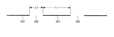
第2のレーザー照射方法において、レーザー光の照射部分と非照射部分が交互に生じるように照射するとは、図1に示すように照射する実施形態を含んでいる。
図1は、レーザー光の照射部分101と隣接するレーザー光の照射部分101の間にあるレーザー光の非照射部分102が交互に生じて、全体として点線状に形成されるように照射した状態を示している。
このとき、繰り返して照射して、図1に示すように外観上1本の点線にすることもできる。繰り返し回数は、例えば1〜20回にすることができる。
複数回照射するときは、レーザー光の照射部分を同じにしてもよいし、レーザー光の照射部分を異ならせる(レーザー光の照射部分をずらす)ことで、金属片全体が粗面化されるようにしてもよい。
レーザー光の照射部分を同じにして複数回照射したときは点線状に照射されるが、レーザー光の照射部分をずらして、即ち、最初はレーザー光の非照射部分であった部分にレーザー光の照射部分が重なるようにずらして照射することを繰り返すと、点線状に照射した場合であっても、最終的には実線状態に照射されることになる。
金属成形体に対して連続的にレーザー光を照射すると、照射面の温度が上昇することから、厚さの小さい成形体ではそりなどの変形が生じるおそれもあるため、冷却するなどの対策が必要になる場合がある。
しかし、図1に示すように点線状にレーザー照射すると、レーザー光の照射部分101とレーザー光の非照射部分102が交互に生じ、レーザー光の非照射部分102では冷却されていることになるため、レーザー光の照射を継続した場合、厚さの小さい成形体でもそりなどの変形が生じ難くなるので好ましい。このとき、上記のようにレーザー光の照射部分を異ならせた(レーザー光の照射部分をずらせた)場合でも、レーザー光の照射時には点線状に照射されているため、同様の効果が得られる。
<Second laser irradiation method>
In the second laser irradiation method, irradiating the laser beam so that the irradiated portion and the non-irradiated portion are alternately generated includes an embodiment of irradiating as shown in FIG.
FIG. 1 shows a state in which non-irradiated
At this time, it is also possible to repeatedly irradiate the line to form a single dotted line in appearance as shown in FIG. The number of repetitions can be, for example, 1 to 20 times.
When irradiating multiple times, the laser beam irradiation portion may be the same, or the laser beam irradiation portion may be different (the laser light irradiation portion is shifted) so that the entire metal piece is roughened. It may be.
When the irradiated part of the laser light is the same and irradiated multiple times, it is irradiated in a dotted line, but the irradiated part of the laser light is shifted, that is, the part that was initially the non-irradiated part of the laser light is irradiated with the laser light. When the irradiation is repeated by shifting the irradiation portions so as to overlap each other, even when the irradiation is performed in a dotted line, the irradiation is finally performed in a solid line state.
When the metal molded body is continuously irradiated with laser light, the temperature of the irradiated surface rises, which may cause deformation such as warping in the molded body with a small thickness, so measures such as cooling are required. May become.
However, when the laser is irradiated in a dotted line as shown in FIG. 1, the
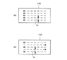
レーザー光の照射方法は、金属成形体110の表面に対して、図2(a)に示すように一方向に照射する方法、または図2(b)に示す点線のように双方向から照射する方法を使用することができる。その他、レーザー光の点線照射部分が交差するように照射する方法でもよい。
照射後の各点線の間隔b1は、金属成形体の照射対象面積などに応じて調整することができるものであるが、例えば、0.01〜5mmの範囲にすることができる。
The laser light irradiation method is a method of irradiating the surface of the metal molded
The interval b1 of each dotted line after irradiation can be adjusted according to the irradiation target area of the metal molded body and the like, and can be, for example, in the range of 0.01 to 5 mm.
図1に示すレーザー光の照射部分101の長さ(L1)とレーザー光の非照射部分102の長さ(L2)は、L1/L2=1/9〜9/1の範囲になるように調整することができる。
レーザー光の照射部分101の長さ(L1)は、複雑な多孔構造に粗面化するためには0.05mm以上であることが好ましく、0.1〜10mmがより好ましく、0.3〜7mmがさらに好ましい。
The length (L1) of the laser beam irradiated
The length (L1) of the laser
第2のレーザー照射方法では、レーザーの駆動電流を直接変換する直接変調方式の変調装置をレーザー電源に接続したファイバーレーザー装置を使用し、デューティ比(duty ratio)を調整してレーザー照射する。
レーザーの励起には、パルス励起と連続励起の2種類があり、パルス励起によるパルス波レーザーは一般にノーマルパルスと呼ばれる。
連続励起であってもパルス波レーザーを作り出すことが可能であり、ノーマルパルスよりパルス幅(パルスON時間)を短くして、その分ピークパワーの高いレーザーを発振させるQスイッチパルス発振方法、AOMやLN光強度変調機により時間的に光を切り出すことでパルス波レーザーを生成させる外部変調方式、レーザーの駆動電流を直接変調してパルス波レーザーを生成する直接変調方式によりパルス波レーザーを作り出すことができる。
上記した好ましい実施形態では、レーザーの駆動電流を直接変換する直接変調方式の変調装置をレーザー電源に接続したファイバーレーザー装置を使用することで、レーザーを連続励起させてパルス波レーザーを作り出したものであり、第1のレーザー照射方法で使用した連続波レーザーとは別のものである。
但し、エネルギー密度、レーザー光の照射速度、レーザー光の出力、波長、ビーム径(スポット径)、焦点はずし距離は、第1のレーザー照射方法と同様に実施する。
In the second laser irradiation method, a fiber laser device in which a direct modulation type modulation device that directly converts the driving current of the laser is connected to a laser power source is used, and the duty ratio is adjusted to irradiate the laser.
There are two types of laser excitation, pulse excitation and continuous excitation, and a pulse wave laser by pulse excitation is generally called a normal pulse.
It is possible to create a pulse wave laser even with continuous excitation, and a Q switch pulse oscillation method that oscillates a laser with a higher peak power by shortening the pulse width (pulse ON time) than a normal pulse, AOM, etc. It is possible to create a pulse wave laser by an external modulation method that generates a pulse wave laser by cutting out light in time with an LN light intensity modulator, and a direct modulation method that directly modulates the drive current of the laser to generate a pulse wave laser. it can.
In the preferred embodiment described above, a pulse wave laser is created by continuously exciting the laser by using a fiber laser device in which a direct modulation type modulation device that directly converts the driving current of the laser is connected to a laser power supply. Yes, it is different from the continuous wave laser used in the first laser irradiation method.
However, the energy density, the irradiation speed of the laser light, the output of the laser light, the wavelength, the beam diameter (spot diameter), and the defocusing distance are the same as those of the first laser irradiation method.
デューティ比は、レーザー光の出力のON時間とOFF時間から次式により求められる比である。
デューティ比(%)=ON時間/(ON時間+OFF時間)×100
デューティ比は、図1に示すL1/L2に対応するものであるから、10〜90%の範囲から選択することができる。
デューティ比を調整してレーザー光を照射することで、図1に示すような点線状に照射することができる。デューティ比が大きいと粗面化工程の効率は良くなるが、冷却効果は低くなり、デューティ比が小さいと冷却効果は良くなるが、粗面化効率は悪くなる。目的に応じて、デューティ比を調整する。
The duty ratio is a ratio obtained by the following equation from the ON time and the OFF time of the laser light output.
Duty ratio (%) = ON time / (ON time + OFF time) x 100
Since the duty ratio corresponds to L1 / L2 shown in FIG. 1, it can be selected from the range of 10 to 90%.
By adjusting the duty ratio and irradiating the laser beam, it is possible to irradiate in a dotted line as shown in FIG. When the duty ratio is large, the efficiency of the roughening process is improved, but the cooling effect is low, and when the duty ratio is small, the cooling effect is good, but the roughening efficiency is poor. Adjust the duty ratio according to the purpose.
第2のレーザー照射工程では、粗面化対象となる金属成形体の表面上に、間隔をおいてレーザー光を通過させないマスキング材を配置した状態でレーザーを連続照射する方法を適用できる。マスキング材は、金属成形体に直接接触しても接触していなくとも良い。複数回照射するときは、マスキング材の位置を変化させることで、金属成形体全体を粗面化させることができる。
この実施形態は、図3(a)のように金属成形体110の上に間隔をおいて複数枚のマスキング材111を配置した状態で、レーザーを連続照射する。マスキング材としては、熱伝導率の小さい金属などを使用することができる。
その後、マスキング材111を取り去ると、図3(b)に示すとおり、図1と同様にレーザー光の照射部分と非照射部分が交互に生じた点線が形成されている。
図3(a)、(b)に示す実施形態の場合にも、マスキング材111の部分では冷却されていることになるため、レーザー光の照射を継続した場合、厚さの小さい成形体でもそりなどの変形が生じ難くなるので好ましい。
In the second laser irradiation step, a method of continuously irradiating a laser can be applied in a state where a masking material that does not allow the laser beam to pass is arranged at intervals on the surface of the metal molded body to be roughened. The masking material may or may not be in direct contact with the metal molded body. When irradiating a plurality of times, the entire metal molded body can be roughened by changing the position of the masking material.
In this embodiment, as shown in FIG. 3A, a plurality of masking
After that, when the masking
Even in the case of the embodiments shown in FIGS. 3 (a) and 3 (b), the masking
レーザー光の照射部分101の長さ(L1)とレーザー光の非照射部分102の長さ(L2)は、L1/L2=1/9〜9/1の範囲になるように調整することができる。
レーザー光の照射部分101の長さ(L1)は、複雑な多孔構造に粗面化するためには0.05mm以上であることが好ましく、0.1〜10mmが好ましく、0.3〜7mmがより好ましい。
The length (L1) of the laser beam irradiated
The length (L1) of the laser
第1のレーザー照射方法と第2レーザー照射方法で使用するレーザーは公知のものを使用することができ、例えば、YVO4レーザー、ファイバーレーザー(シングルモードファイバーレーザー、マルチモードファイバーレーザー)、エキシマレーザー、炭酸ガスレーザー、紫外線レーザー、YAGレーザー、半導体レーザー、ガラスレーザー、ルビーレーザー、He−Neレーザー、窒素レーザー、キレートレーザー、色素レーザーを使用することができる。 As the laser used in the first laser irradiation method and the second laser irradiation method, known lasers can be used, for example, YVO 4 laser, fiber laser (single mode fiber laser, multi mode fiber laser), excima laser, and the like. Carbon dioxide lasers, ultraviolet lasers, YAG lasers, semiconductor lasers, glass lasers, ruby lasers, He-Ne lasers, nitrogen lasers, chelate lasers, and dye lasers can be used.
レーザー光照射して粗面化する工程において、第1のレーザー照射方法または第2レーザー照射方法を実施したときは、上記したエネルギー密度と照射速度を満たすように金属成形体にレーザー光を照射すると、金属成形体の表面は溶融しながら一部が蒸発されることから、複雑な構造の多孔構造が形成される。
このときに形成される多孔構造は、特許第5774246号公報の図7、図8、特許第5701414号公報の図7、図8に示されるものと同じ複雑な多孔構造か、類似する多孔構造である。
一方、上記したエネルギー密度と照射速度を満たさない場合には、金属成形体の表面は昇華して孔が形成されるか(通常のパルスレーザー照射により形成される孔)、または溶融(レーザー溶接)してしまい、複雑な構造の孔は形成されない。
When the first laser irradiation method or the second laser irradiation method is carried out in the step of irradiating the surface with a laser beam, the metal molded body is irradiated with the laser beam so as to satisfy the above energy density and irradiation rate. Since the surface of the metal molded body is partially evaporated while melting, a porous structure having a complicated structure is formed.
The porous structure formed at this time is the same complicated porous structure as that shown in FIGS. 7 and 8 of Japanese Patent No. 5774246 and FIGS. 7 and 8 of Japanese Patent No. 5701414, or a similar porous structure. is there.
On the other hand, when the above energy density and irradiation rate are not satisfied, the surface of the metal molded body is sublimated to form holes (holes formed by ordinary pulse laser irradiation) or melted (laser welding). Therefore, holes with a complicated structure are not formed.
次の工程にて、前工程において粗面化された金属成形体の接合面(レーザー光照射部17a、17b)を金型内に配置して、前記樹脂成形体となる樹脂を射出成形して前記開口部をシールする。
射出成形時において粗面化された接合面(レーザー光照射部17a、17b)の多孔構造内部に溶融状態の樹脂が入り込んだ後で固まることで、金属成形体の接合面(レーザー光照射部)と樹脂成形体の間が強い接合力で一体化される。
In the next step, the joint surfaces (laser light irradiation portions 17a and 17b) of the metal molded body roughened in the previous step are arranged in the mold, and the resin to be the resin molded body is injection-molded. Seal the opening.
The joint surface (laser light irradiation part) of the metal molded body is solidified after the molten resin enters the inside of the porous structure of the joint surface (laser light irradiation part 17a, 17b) that has been roughened during injection molding. And the resin molded body are integrated with a strong bonding force.
樹脂成形体に使用する樹脂は、熱可塑性樹脂、熱硬化性樹脂のほか、熱可塑性エラストマーも含まれる。
熱可塑性樹脂は、用途に応じて公知の熱可塑性樹脂から適宜選択することができる。例えば、ポリアミド系樹脂(PA6、PA66等の脂肪族ポリアミド、芳香族ポリアミド)、ポリスチレン、ABS樹脂、AS樹脂等のスチレン単位を含む共重合体、ポリエチレン、エチレン単位を含む共重合体、ポリプロピレン、プロピレン単位を含む共重合体、その他のポリオレフィン、ポリ塩化ビニル、ポリ塩化ビニリデン、ポリカーボネート系樹脂、アクリル系樹脂、メタクリル系樹脂、ポリエステル系樹脂、ポリアセタール系樹脂、ポリフェニレンスルフィド系樹脂を挙げることができる。
The resin used for the resin molded product includes a thermoplastic resin, a thermosetting resin, and a thermoplastic elastomer.
The thermoplastic resin can be appropriately selected from known thermoplastic resins according to the intended use. For example, polyamide resins (aliphatic polyamides such as PA6 and PA66, aromatic polyamides), copolymers containing styrene units such as polystyrene, ABS resin and AS resin, polyethylene and copolymers containing ethylene units, polypropylene and propylene. Examples thereof include copolymers containing units, other polyolefins, polyvinyl chloride, polyvinylidene chloride, polycarbonate resins, acrylic resins, methacrylic resins, polyester resins, polyacetal resins, and polyphenylene sulfide resins.
熱硬化性樹脂は、用途に応じて公知の熱硬化性樹脂から適宜選択することができる。例えば、尿素樹脂、メラミン樹脂、フェノール樹脂、レソルシノール樹脂、エポキシ樹脂、ポリウレタン、ビニルウレタンを挙げることができる。 The thermosetting resin can be appropriately selected from known thermosetting resins depending on the intended use. For example, urea resin, melamine resin, phenol resin, resorcinol resin, epoxy resin, polyurethane, vinyl urethane can be mentioned.
熱可塑性エラストマーは、用途に応じて公知の熱可塑性エラストマーから適宜選択することができる。例えば、スチレン系エラストマー、塩化ビニル系エラストマー、オレフィン系エラストマー、ウレタン系エラストマー、ポリエステル系エラストマー、ニトリル系エラストマー、ポリアミド系エラストマーを挙げることができる。 The thermoplastic elastomer can be appropriately selected from known thermoplastic elastomers depending on the application. For example, styrene-based elastomers, vinyl chloride-based elastomers, olefin-based elastomers, urethane-based elastomers, polyester-based elastomers, nitrile-based elastomers, and polyamide-based elastomers can be mentioned.
これらの熱可塑性樹脂、熱硬化性樹脂、熱可塑性エラストマーには、公知の繊維状充填材を配合することができる。
公知の繊維状充填材としては、炭素繊維、無機繊維、金属繊維、有機繊維等を挙げることができる。
炭素繊維は周知のものであり、PAN系、ピッチ系、レーヨン系、リグニン系等のものを用いることができる。
無機繊維としては、ガラス繊維、玄武岩繊維、シリカ繊維、シリカ・アルミナ繊維、ジルコニア繊維、窒化ホウ素繊維、窒化ケイ素繊維等を挙げることができる。
金属繊維としては、ステンレス、アルミニウム、銅等からなる繊維を挙げることができる。
有機繊維としては、ポリアミド繊維(全芳香族ポリアミド繊維、ジアミンとジカルボン酸のいずれか一方が芳香族化合物である半芳香族ポリアミド繊維、脂肪族ポリアミド繊維)、ポリビニルアルコール繊維、アクリル繊維、ポリオレフィン繊維、ポリオキシメチレン繊維、ポリテトラフルオロエチレン繊維、ポリエステル繊維(全芳香族ポリエステル繊維を含む)、ポリフェニレンスルフィド繊維、ポリイミド繊維、液晶ポリエステル繊維などの合成繊維や天然繊維(セルロース系繊維など)や再生セルロース(レーヨン)繊維などを用いることができる。
A known fibrous filler can be blended with these thermoplastic resins, thermosetting resins, and thermoplastic elastomers.
Examples of known fibrous fillers include carbon fibers, inorganic fibers, metal fibers, and organic fibers.
Carbon fibers are well known, and PAN-based, pitch-based, rayon-based, lignin-based, and the like can be used.
Examples of the inorganic fiber include glass fiber, genbuiwa fiber, silica fiber, silica / alumina fiber, zirconia fiber, boron nitride fiber, silicon nitride fiber and the like.
Examples of the metal fiber include fibers made of stainless steel, aluminum, copper and the like.
Examples of organic fibers include polyamide fibers (total aromatic polyamide fibers, semi-aromatic polyamide fibers in which one of diamine and dicarboxylic acid is an aromatic compound, aliphatic polyamide fibers), polyvinyl alcohol fibers, acrylic fibers, and polyolefin fibers. Synthetic fibers such as polyoxymethylene fiber, polytetrafluoroethylene fiber, polyester fiber (including all aromatic polyester fiber), polyphenylene sulfide fiber, polyimide fiber, liquid crystal polyester fiber, natural fiber (cellulose fiber, etc.) and regenerated cellulose (cellulosic fiber, etc.) Rayon) Fiber or the like can be used.
これらの繊維状充填材は、繊維径が3〜60μmの範囲のものを使用することができるが、これらの中でも、例えば金属成形体10の接合面12が粗面化されて形成される開放孔30などの開口径より小さな繊維径のものを使用することが好ましい。繊維径は、より望ましくは5〜30μm、さらに望ましくは7〜20μmである。
As these fibrous fillers, those having a fiber diameter in the range of 3 to 60 μm can be used. Among these, for example, open holes formed by roughening the joint surface 12 of the metal molded
本発明の製造方法では、粗面化された金属成形体の接合面が、表面から最大深さが500μmを超える孔を含む多孔構造を有しており、前記多孔構造内部に樹脂が入り込んだ状態で、金属成形体と樹脂成形体が一体化されている。
本発明の製造方法で得られた複合成形体は、前記金属成形体と前記樹脂成形体の接合強度が60MPa以上のものである。
本発明の製造方法で得られた複合成形体は、金属成形体に形成された孔(溝)の最大深さが500μmを超える深さであること、孔(溝)深さが深いと孔(溝)の開口部が大きくなって溶融状態の樹脂(繊維も含む)が入り易くなることから、接合強度が大きくなるものと考えられる。
In the production method of the present invention, the joint surface of the roughened metal molded body has a porous structure including holes having a maximum depth of more than 500 μm from the surface, and the resin has entered the inside of the porous structure. Therefore, the metal molded body and the resin molded body are integrated.
The composite molded product obtained by the production method of the present invention has a bonding strength of 60 MPa or more between the metal molded product and the resin molded product.
In the composite molded body obtained by the production method of the present invention, the maximum depth of the holes (grooves) formed in the metal molded body is more than 500 μm, and the holes (grooves) are deep. Since the opening of the groove) becomes large and the molten resin (including fibers) can easily enter, it is considered that the bonding strength is increased.
実施例1〜3、比較例1、2
実施例および比較例は、図4に示す金属成形体(アルミニウム:A5052)10の接合面11全面(40mm2の広さ範囲)に対して、表1に示す条件でレーザー光を第1のレーザー光照射方法により連続照射してレーザー光照射面を粗面化した。
なお、照射パターンは図2(b)と同じ双方向であるが、第1のレーザー光照射方法(レーザー光の連続照射)であるから、図2(b)と同じ照射パターンで、かつ実線で示される照射パターンになる。
レーザー装置は次のものを使用した。
発振機:IPG-Ybファイバー;YLR−300−SMAC
集光系:fc=80mm/fθ=100mm
Examples 1 to 3, Comparative Examples 1 and 2
In the examples and comparative examples, the first laser beam was applied to the entire surface 11 of the joint surface (area of 40 mm 2 ) of the metal molded body (aluminum: A5052) 10 shown in FIG. 4 under the conditions shown in Table 1. The surface irradiated with the laser beam was roughened by continuous irradiation by the light irradiation method.
The irradiation pattern is the same bidirectional as in FIG. 2 (b), but since it is the first laser light irradiation method (continuous irradiation of laser light), the irradiation pattern is the same as in FIG. 2 (b) and the solid line is used. The irradiation pattern shown is obtained.
The following laser devices were used.
Oscillator: IPG-Yb fiber; YLR-300-SMAC
Condensing system: fc = 80mm / fθ = 100mm
次に、処理後の金属成形体を使用して、下記の方法で射出成形して、実施例および比較例の金属成形体10と樹成形体20からなる図5に示す複合成形体1を得た。樹脂成形体20は、金属成形体10と同形状および同寸法である。
Next, using the treated metal molded body, injection molding is performed by the following method to obtain a composite molded body 1 shown in FIG. 5, which is composed of the metal molded
<射出成形>
GF30%強化PA6樹脂(プラストロンPA6-GF30-01,長さ9mm:ダイセルポリマー(株)製)
樹脂温度:280℃
金型温度:100℃
射出成形機:ファナック製ROBOSHOT S2000i100B)
<Injection molding>
GF30% reinforced PA6 resin (Plastron PA6-GF30-01, length 9 mm: manufactured by Daicel Polymer Co., Ltd.)
Resin temperature: 280 ° C
Mold temperature: 100 ° C
Injection molding machine: ROBOSHOT S2000i100B made by FANUC)
(溝深さ)
溝(孔)の最大深さは、レーザー光照射後の面(40mm2の広さ範囲)の一部(1mm×1mm=1mm2の面積)を選び、デジタルマイクロスコープM205C(ライカ・マイクロシステムズ(株))で測定した。具体的には、1mm×1mm の正方形に100μm間隔で平行に9本の直線を引き、その直線部分の断面観察から深さを測定した。この測定を10箇所の部分で測定し、その測定の中で最大の深さを最大深さとした。
平均溝(孔)深さも、上記方法で個々の深さを測定しその数平均値として評価した。
最大溝(孔)深さは、前記デジタルマイクロスコープにより測定可能な範囲を超えたときは、測定可能な範囲内を最大値とした。
(Groove depth)
For the maximum depth of the groove (hole), select a part (1 mm x 1 mm = 1 mm 2 area) of the surface (40 mm 2 area) after laser irradiation, and select the digital microscope M205C (Leica Microsystems (Leica Microsystems)). Co., Ltd.). Specifically, nine straight lines were drawn in parallel at 100 μm intervals on a 1 mm × 1 mm square, and the depth was measured by observing the cross section of the straight lines. This measurement was measured at 10 points, and the maximum depth was taken as the maximum depth.
The average groove (hole) depth was also evaluated as the average value of the individual depths measured by the above method.
When the maximum groove (hole) depth exceeds the measurable range by the digital microscope, the maximum value is within the measurable range.
〔引張試験〕
実施例および比較例の図4に示す複合成形体を用い、引張試験を行ってせん断接合強度を評価した。結果を表1に示す。
引張試験は、樹脂成形体20側の端部を固定した状態で図5に示すX方向に引っ張った場合の金属成形体10と樹脂成形体20の接合面が破壊されるまでの最大荷重を測定した。
<引張試験条件>
試験機:(株)島津製作所製のオートグラフAG-X plus(50kN)
引張速度:10mm/min
チャック間距離:50mm
[Tensile test]
Using the composite molded bodies shown in FIG. 4 of Examples and Comparative Examples, a tensile test was performed to evaluate the shear joint strength. The results are shown in Table 1.
In the tensile test, the maximum load until the joint surface between the metal molded
<Tensile test conditions>
Testing machine: Autograph AG-X plus (50kN) manufactured by Shimadzu Corporation
Tensile speed: 10 mm / min
Distance between chucks: 50 mm

実施例1〜4の対比から、焦点はずし距離をマイナス(−)にすることで最大溝深さがより深くなったことが確認できた。
実施例1、2と比較例1、2の対比から、レーザー光照射の繰り返し回数を増加させることで、平均溝深さと最大溝深さがより深くなったことが確認できた。
実施例と比較例の対比から、最大溝深さの違いにより接合強度に明確な差が生じたことが確認できた。
From the comparison of Examples 1 to 4, it was confirmed that the maximum groove depth became deeper by setting the defocusing distance to minus (-).
From the comparison between Examples 1 and 2 and Comparative Examples 1 and 2, it was confirmed that the average groove depth and the maximum groove depth became deeper by increasing the number of repetitions of laser light irradiation.
From the comparison between the examples and the comparative examples, it was confirmed that there was a clear difference in the joint strength due to the difference in the maximum groove depth.
本発明の複合成形体の製造方法は、金属製品の一部を樹脂成形体で代替して軽量化するために利用することができる。 The method for producing a composite molded product of the present invention can be used to replace a part of a metal product with a resin molded product to reduce the weight.
Claims (6)
前記金属成形体の前記繊維径5〜30μmの繊維状充填材を含有する樹脂成形体との接合面に対して、エネルギー密度1MW/cm2以上で、照射速度2000mm/sec以上、レーザー光の焦点はずし距離を−0.5〜−0.05mmでレーザー光を照射して粗面化する工程と、
前工程において粗面化された金属成形体の接合面を含む部分を金型内に配置し、繊維径5〜30μmの繊維状充填材を含有する樹脂を射出成形して複合成形体を得る工程を有しており、
前記粗面化された金属成形体の接合面が、表面から最大深さが500μmを超え、表面からの平均深さが400〜600μmの孔を含む多孔構造を有しており、
前記金属成形体と前記繊維径5〜30μmの繊維状充填材を含有する樹脂成形体の接合強度が60MPa以上である、複合成形体の製造方法。 A method for producing a composite molded body in which a metal molded body and a resin molded body containing a fibrous filler having a fiber diameter of 5 to 30 μm are joined.
With respect to the joint surface of the metal molded product with the resin molded product containing the fibrous filler having a fiber diameter of 5 to 30 μm , the energy density is 1 MW / cm 2 or more, the irradiation speed is 2000 mm / sec or more, and the focal point of the laser beam is A process of irradiating a laser beam with a removal distance of -0.5 to -0.05 mm to roughen the surface, and
A step of arranging a portion including a joint surface of a metal molded body roughened in the previous step in a mold and injection molding a resin containing a fibrous filler having a fiber diameter of 5 to 30 μm to obtain a composite molded body. Have and
The joint surface of the roughened metal molded body has a porous structure including holes having a maximum depth of more than 500 μm from the surface and an average depth of 400 to 600 μm from the surface.
A method for producing a composite molded product, wherein the bonding strength between the metal molded product and the resin molded product containing the fibrous filler having a fiber diameter of 5 to 30 μm is 60 MPa or more.
Priority Applications (7)
| Application Number | Priority Date | Filing Date | Title |
|---|---|---|---|
| JP2016240306A JP6859087B2 (en) | 2016-12-12 | 2016-12-12 | Manufacturing method of composite molded product |
| CN201780076788.6A CN110072683A (en) | 2016-12-12 | 2017-12-11 | The manufacturing method and composite shaped body of composite shaped body |
| KR1020197016664A KR20190091454A (en) | 2016-12-12 | 2017-12-11 | Manufacturing method and composite molded body |
| US16/465,901 US20190299335A1 (en) | 2016-12-12 | 2017-12-11 | Method for manufacturing composite molded body and composite molded body |
| EP17880694.9A EP3552793A4 (en) | 2016-12-12 | 2017-12-11 | Method for producing composite moulded body, and composite moulded body |
| PCT/JP2017/044388 WO2018110505A1 (en) | 2016-12-12 | 2017-12-11 | Method for producing composite moulded body, and composite moulded body |
| TW106143481A TW201834851A (en) | 2016-12-12 | 2017-12-12 | Method for producing composite moulded body, and composite moulded body |
Applications Claiming Priority (1)
| Application Number | Priority Date | Filing Date | Title |
|---|---|---|---|
| JP2016240306A JP6859087B2 (en) | 2016-12-12 | 2016-12-12 | Manufacturing method of composite molded product |
Publications (2)
| Publication Number | Publication Date |
|---|---|
| JP2018094778A JP2018094778A (en) | 2018-06-21 |
| JP6859087B2 true JP6859087B2 (en) | 2021-04-14 |
Family
ID=62559124
Family Applications (1)
| Application Number | Title | Priority Date | Filing Date |
|---|---|---|---|
| JP2016240306A Active JP6859087B2 (en) | 2016-12-12 | 2016-12-12 | Manufacturing method of composite molded product |
Country Status (7)
| Country | Link |
|---|---|
| US (1) | US20190299335A1 (en) |
| EP (1) | EP3552793A4 (en) |
| JP (1) | JP6859087B2 (en) |
| KR (1) | KR20190091454A (en) |
| CN (1) | CN110072683A (en) |
| TW (1) | TW201834851A (en) |
| WO (1) | WO2018110505A1 (en) |
Families Citing this family (1)
| Publication number | Priority date | Publication date | Assignee | Title |
|---|---|---|---|---|
| WO2020149248A1 (en) * | 2019-01-15 | 2020-07-23 | 昭和電工株式会社 | Composite laminate, method for producing same, and metal-resin joined body |
Family Cites Families (17)
| Publication number | Priority date | Publication date | Assignee | Title |
|---|---|---|---|---|
| JPS5372066A (en) | 1976-12-09 | 1978-06-27 | Sumitomo Electric Industries | Insert apparatus for injection molding machine |
| JP2002331377A (en) * | 2001-05-08 | 2002-11-19 | Koike Sanso Kogyo Co Ltd | Laser piercing method |
| US6723090B2 (en) * | 2001-07-02 | 2004-04-20 | Palomar Medical Technologies, Inc. | Fiber laser device for medical/cosmetic procedures |
| JP4750720B2 (en) * | 2004-12-08 | 2011-08-17 | 三星ダイヤモンド工業株式会社 | Method for forming split starting point in split object, splitting method for split object |
| JP2009051131A (en) * | 2007-08-28 | 2009-03-12 | Toyoda Gosei Co Ltd | Composite body of metal and resin, and method of manufacturing the same |
| JP2013052669A (en) * | 2010-12-28 | 2013-03-21 | Daicel Corp | Method for manufacturing composite molded body |
| CN102610998B (en) * | 2012-03-16 | 2013-04-24 | 中国科学院上海微系统与信息技术研究所 | Driving device for pulse laser |
| JP5774246B2 (en) | 2013-03-26 | 2015-09-09 | ダイセルポリマー株式会社 | Method of roughening a metal molded body |
| JP5701414B1 (en) * | 2013-03-26 | 2015-04-15 | ダイセルポリマー株式会社 | Method for producing composite molded body |
| KR20160034260A (en) | 2013-07-18 | 2016-03-29 | 다이셀폴리머 주식회사 | Composite moulded body |
| JP6326782B2 (en) * | 2013-11-22 | 2018-05-23 | Dic株式会社 | Metal resin joint molding |
| DE102014008815A1 (en) * | 2014-06-11 | 2016-01-21 | Albis Plastic Gmbh | Method for producing a composite material of metal and plastic to a plastic-metal hybrid component |
| JP6422701B2 (en) | 2014-08-08 | 2018-11-14 | ダイセルポリマー株式会社 | Abrasive |
| JP6510296B2 (en) | 2014-08-19 | 2019-05-08 | ダイセルポリマー株式会社 | Method of roughening metal molded body |
| JP6353320B2 (en) | 2014-08-25 | 2018-07-04 | ダイセルポリマー株式会社 | Method for producing composite molded body |
| JP6472655B2 (en) * | 2014-12-25 | 2019-02-20 | ダイセルポリマー株式会社 | Pipe joint structure and manufacturing method thereof |
| JP6685645B2 (en) * | 2015-01-08 | 2020-04-22 | ダイセルポリマー株式会社 | Method for producing metal molded body having porous structure in surface layer portion |
-
2016
- 2016-12-12 JP JP2016240306A patent/JP6859087B2/en active Active
-
2017
- 2017-12-11 CN CN201780076788.6A patent/CN110072683A/en active Pending
- 2017-12-11 WO PCT/JP2017/044388 patent/WO2018110505A1/en active Application Filing
- 2017-12-11 US US16/465,901 patent/US20190299335A1/en not_active Abandoned
- 2017-12-11 KR KR1020197016664A patent/KR20190091454A/en unknown
- 2017-12-11 EP EP17880694.9A patent/EP3552793A4/en not_active Withdrawn
- 2017-12-12 TW TW106143481A patent/TW201834851A/en unknown
Also Published As
| Publication number | Publication date |
|---|---|
| KR20190091454A (en) | 2019-08-06 |
| WO2018110505A1 (en) | 2018-06-21 |
| EP3552793A4 (en) | 2020-08-12 |
| CN110072683A (en) | 2019-07-30 |
| TW201834851A (en) | 2018-10-01 |
| JP2018094778A (en) | 2018-06-21 |
| US20190299335A1 (en) | 2019-10-03 |
| EP3552793A1 (en) | 2019-10-16 |
Similar Documents
| Publication | Publication Date | Title |
|---|---|---|
| US10434741B2 (en) | Composite molded article | |
| JP6317064B2 (en) | Composite molded body and manufacturing method thereof | |
| JP6887411B2 (en) | Roughening method of metal molded body | |
| KR20190042571A (en) | Hybrid composite between metal surface and polymer material surface and method of making same | |
| JP7161571B2 (en) | Composite molded article and its manufacturing method | |
| KR102111948B1 (en) | Different material joint body and method for manufacturing the same | |
| JP5639046B2 (en) | Laser processing apparatus and laser processing method | |
| JP2015142960A (en) | Method of producing composite molded body | |
| KR102359488B1 (en) | A method for roughening a metal molded body | |
| JP6329598B2 (en) | Method for producing composite molded body | |
| JP6859087B2 (en) | Manufacturing method of composite molded product | |
| JP6158866B2 (en) | Method for producing composite molded body | |
| JP6787648B2 (en) | How to manage the unevenness of the surface of the metal molded body | |
| JP7209153B2 (en) | Nitride-based non-magnetic ceramic compact | |
| JP7446810B2 (en) | Manufacturing method of composite molded body | |
| Jung et al. | Ultra high speed laser cutting of CFRP using a scanner head | |
| JPWO2019216439A1 (en) | Complex and method for producing complex | |
| JP2009270632A (en) | Manufacturing method of splice plate |
Legal Events
| Date | Code | Title | Description |
|---|---|---|---|
| A521 | Written amendment |
Free format text: JAPANESE INTERMEDIATE CODE: A523 Effective date: 20161213 |
|
| A625 | Written request for application examination (by other person) |
Free format text: JAPANESE INTERMEDIATE CODE: A625 Effective date: 20191003 |
|
| A131 | Notification of reasons for refusal |
Free format text: JAPANESE INTERMEDIATE CODE: A131 Effective date: 20200915 |
|
| A521 | Written amendment |
Free format text: JAPANESE INTERMEDIATE CODE: A523 Effective date: 20201027 |
|
| A02 | Decision of refusal |
Free format text: JAPANESE INTERMEDIATE CODE: A02 Effective date: 20201110 |
|
| A521 | Written amendment |
Free format text: JAPANESE INTERMEDIATE CODE: A523 Effective date: 20210205 |
|
| C60 | Trial request (containing other claim documents, opposition documents) |
Free format text: JAPANESE INTERMEDIATE CODE: C60 Effective date: 20210205 |
|
| A911 | Transfer to examiner for re-examination before appeal (zenchi) |
Free format text: JAPANESE INTERMEDIATE CODE: A911 Effective date: 20210226 |
|
| C21 | Notice of transfer of a case for reconsideration by examiners before appeal proceedings |
Free format text: JAPANESE INTERMEDIATE CODE: C21 Effective date: 20210302 |
|
| TRDD | Decision of grant or rejection written | ||
| A01 | Written decision to grant a patent or to grant a registration (utility model) |
Free format text: JAPANESE INTERMEDIATE CODE: A01 Effective date: 20210323 |
|
| A61 | First payment of annual fees (during grant procedure) |
Free format text: JAPANESE INTERMEDIATE CODE: A61 Effective date: 20210325 |
|
| R150 | Certificate of patent or registration of utility model |
Ref document number: 6859087 Country of ref document: JP Free format text: JAPANESE INTERMEDIATE CODE: R150 |