JP6858905B2 - Magnetic recording medium and magnetic recording / playback device - Google Patents
Magnetic recording medium and magnetic recording / playback device Download PDFInfo
- Publication number
- JP6858905B2 JP6858905B2 JP2020122790A JP2020122790A JP6858905B2 JP 6858905 B2 JP6858905 B2 JP 6858905B2 JP 2020122790 A JP2020122790 A JP 2020122790A JP 2020122790 A JP2020122790 A JP 2020122790A JP 6858905 B2 JP6858905 B2 JP 6858905B2
- Authority
- JP
- Japan
- Prior art keywords
- magnetic
- recording medium
- magnetic recording
- powder
- magnetic layer
- Prior art date
- Legal status (The legal status is an assumption and is not a legal conclusion. Google has not performed a legal analysis and makes no representation as to the accuracy of the status listed.)
- Active
Links
Images
Landscapes
- Magnetic Record Carriers (AREA)
Description
本発明は、磁気記録媒体および磁気記録再生装置に関する。 The present invention relates to a magnetic recording medium and a magnetic recording / playback device.
近年、各種データを記録し保管するためのデータストレージ用記録媒体として、磁気記録媒体が広く用いられている(例えば特許文献1参照)。 In recent years, a magnetic recording medium has been widely used as a data storage recording medium for recording and storing various types of data (see, for example, Patent Document 1).
磁気記録媒体に記録されたデータの再生は、通常、磁気記録媒体を磁気記録再生装置内で走行させながら、磁気ヘッドを磁性層表面と接触させ摺動させて磁性層に記録されたデータを読み取ることによって行われる。しかし、磁気記録媒体が走行安定性に劣るものであると、オフトラックにより再生出力が低下してしまう。そのため、磁気記録媒体には、走行安定性に優れることが望まれる。 To reproduce the data recorded on the magnetic recording medium, the data recorded on the magnetic layer is usually read by sliding the magnetic head in contact with the surface of the magnetic layer while running the magnetic recording medium in the magnetic recording / reproducing device. It is done by. However, if the magnetic recording medium is inferior in running stability, the reproduction output is lowered due to off-track. Therefore, it is desired that the magnetic recording medium has excellent running stability.
磁気記録媒体等の各種記録媒体に記録されるデータは、アクセス頻度(再生頻度)に応じて、ホットデータ、ウォームデータ、コールドデータと呼ばれる。アクセス頻度は、ホットデータ、ウォームデータ、コールドデータの順に低くなり、アクセス頻度が低いデータ(例えばコールドデータ)を記録し長期間保管することは、アーカイブ(archive)と呼ばれる。近年の情報量の飛躍的な増大および各種情報のデジタル化に伴い、アーカイブのために記録媒体に記録し保管されるデータ量は増大しているため、アーカイブに適した記録再生システムに対する注目が高まりつつある。 Data recorded on various recording media such as magnetic recording media are called hot data, warm data, and cold data according to the access frequency (reproduction frequency). The access frequency decreases in the order of hot data, warm data, and cold data, and recording and storing data with low access frequency (for example, cold data) for a long period of time is called an archive. With the dramatic increase in the amount of information in recent years and the digitization of various types of information, the amount of data recorded and stored on recording media for archiving is increasing, so attention is increasing to recording and playback systems suitable for archiving. It's getting better.
上記のような長期保管後、データを再生する際に優れた走行安定性を示すことができる磁気記録媒体は、アーカイブ用記録媒体として好適である。 A magnetic recording medium capable of exhibiting excellent running stability when reproducing data after long-term storage as described above is suitable as a recording medium for archiving.
以上に鑑み、本発明の一態様は、長期保管後の走行安定性に優れる磁気記録媒体を提供することを目的とする。 In view of the above, one aspect of the present invention is to provide a magnetic recording medium having excellent running stability after long-term storage.
本発明の一態様は、
非磁性支持体上に強磁性粉末を含む磁性層を有する磁気記録媒体であって、
上記非磁性支持体上の磁性層側の部分に、脂肪酸および脂肪酸アミドからなる群から選ばれる成分の一種以上を含み、
上記磁性層を70atmの圧力で押圧した後に、この磁性層の表面において光電子取り出し角10度で行われるX線光電子分光分析により得られるC1sスペクトルにおけるC−Hピーク面積率から算出されるC−H由来C濃度(以下、「押圧後C−H由来C濃度」または「C−H由来C濃度」とも記載する。)が45原子%以上である磁気記録媒体、
に関する。単位に関して、1atm=101325Pa(パスカル)=101325N(ニュートン)/m2である。
One aspect of the present invention is
A magnetic recording medium having a magnetic layer containing ferromagnetic powder on a non-magnetic support.
The portion on the non-magnetic support on the magnetic layer side contains one or more components selected from the group consisting of fatty acids and fatty acid amides.
After pressing the magnetic layer with a pressure of 70 atm, CH calculated from the CH peak area ratio in the C1s spectrum obtained by X-ray photoelectron spectroscopy performed at a photoelectron extraction angle of 10 degrees on the surface of the magnetic layer. A magnetic recording medium having a derived C concentration (hereinafter, also referred to as “CH-derived C concentration after pressing” or “CH-derived C concentration”) of 45 atomic% or more.
Regarding. Regarding the unit, 1 atm = 101325 Pa (Pascal) = 101325 N (Newton) / m 2 .
一形態では、上記押圧後C−H由来C濃度は、45原子%以上80原子%以下であることができる。 In one form, the C-H-derived C concentration after pressing can be 45 atomic% or more and 80 atomic% or less.
一形態では、上記磁性層は、無機酸化物系粒子を含むことができる。 In one form, the magnetic layer can contain inorganic oxide particles.
一形態では、上記無機酸化物系粒子は、無機酸化物とポリマーとの複合粒子であることができる。 In one form, the inorganic oxide-based particles can be composite particles of an inorganic oxide and a polymer.
一形態では、上記磁気記録媒体は、上記非磁性支持体と上記磁性層との間に、非磁性粉末を含む非磁性層を有することができる。 In one form, the magnetic recording medium can have a non-magnetic layer containing non-magnetic powder between the non-magnetic support and the magnetic layer.
一形態では、上記磁気記録媒体は、上記非磁性支持体の上記磁性層を有する表面側とは反対の表面側に、非磁性粉末を含むバックコート層を有することができる。 In one form, the magnetic recording medium may have a backcoat layer containing non-magnetic powder on the surface side of the non-magnetic support opposite to the surface side having the magnetic layer.
一形態では、上記磁気記録媒体は、磁気テープであることができる。 In one form, the magnetic recording medium can be a magnetic tape.
本発明の一態様は、上記磁気記録媒体と、磁気ヘッドと、を含む磁気記録再生装置に関する。 One aspect of the present invention relates to a magnetic recording / reproducing device including the magnetic recording medium and a magnetic head.
本発明の一態様によれば、長期保管後の走行安定性に優れる磁気記録媒体を提供することができる。また、本発明の一態様によれば、上記磁気記録媒体を含む磁気記録再生装置を提供することができる。 According to one aspect of the present invention, it is possible to provide a magnetic recording medium having excellent running stability after long-term storage. Further, according to one aspect of the present invention, it is possible to provide a magnetic recording / reproducing device including the above magnetic recording medium.
[磁気記録媒体]
本発明の一態様は、非磁性支持体上に強磁性粉末を含む磁性層を有する磁気記録媒体であって、上記非磁性支持体上の磁性層側の部分に、脂肪酸および脂肪酸アミドからなる群から選ばれる成分の一種以上を含み、上記磁性層を70atmの圧力で押圧した後に、この磁性層の表面において光電子取り出し角10度で行われるX線光電子分光分析により得られるC1sスペクトルにおけるC−Hピーク面積率から算出されるC−H由来C濃度(押圧後C−H由来C濃度)が45原子%以上である磁気記録媒体に関する。
[Magnetic recording medium]
One aspect of the present invention is a magnetic recording medium having a magnetic layer containing a ferromagnetic powder on a non-magnetic support, in which a portion of the non-magnetic support on the magnetic layer side is composed of a fatty acid and a fatty acid amide. CH in the C1s spectrum obtained by X-ray photoelectron spectroscopic analysis performed on the surface of the magnetic layer at a photoelectron extraction angle of 10 degrees after pressing the magnetic layer with a pressure of 70 atm, which contains one or more of the components selected from The present invention relates to a magnetic recording medium in which the CH-derived C concentration calculated from the peak area ratio (CH-derived C concentration after pressing) is 45 atomic% or more.
上記の磁性層を押圧する圧力70atmは、押圧により磁性層の表面に加わる面圧である。20m/minの速度で磁気記録媒体を走行させながら、2つのロール間を通過させることにより、磁性層の表面に70atmの面圧が加えられる。走行中の磁気記録媒体には、走行方向に0.5N/mの張力が加えられる。例えば、テープ状の磁気記録媒体(即ち磁気テープ)については、走行中の磁気テープの長手方向に0.5N/mの張力が加えられる。上記押圧は、磁気記録媒体を2つのロール間を合計6回通過させ、各ロール間を通過する際にそれぞれ70atmの面圧を加えて行う。上記ロールとしては、金属ロールを使用し、ロールは加熱しない。押圧を行う環境は、雰囲気温度20〜25℃、相対湿度40〜60%の環境とする。上記の押圧が行われる磁気記録媒体は、相対湿度40〜60%の室温環境下での10年以上の長期保管も、かかる長期保管に相当する保管またはかかる長期保管に相当する加速試験も行われていない磁気記録媒体とする。この点は、特記しない限り、本発明および本明細書に記載の磁気記録媒体に関する各種物性についても同様とする。
以上の押圧は、例えば、磁気記録媒体の製造のために使用されるカレンダ処理機を利用して行うことができる。例えば、磁気テープカートリッジに収容されている磁気テープを取り出し、カレンダ処理機においてカレンダロール間を通過させることにより、磁気テープを70atmの圧力で押圧することができる。
The pressure of 70 atm for pressing the magnetic layer is a surface pressure applied to the surface of the magnetic layer by pressing. A surface pressure of 70 atm is applied to the surface of the magnetic layer by passing between the two rolls while running the magnetic recording medium at a speed of 20 m / min. A tension of 0.5 N / m is applied to the traveling magnetic recording medium in the traveling direction. For example, for a tape-shaped magnetic recording medium (that is, a magnetic tape), a tension of 0.5 N / m is applied in the longitudinal direction of the running magnetic tape. The pressing is performed by passing the magnetic recording medium between the two rolls a total of 6 times, and applying a surface pressure of 70 atm when passing between the rolls. A metal roll is used as the roll, and the roll is not heated. The pressing environment is an environment having an ambient temperature of 20 to 25 ° C. and a relative humidity of 40 to 60%. The magnetic recording medium to which the above pressing is performed is subjected to long-term storage for 10 years or more in a room temperature environment of 40 to 60% relative humidity, storage corresponding to such long-term storage, or accelerated test corresponding to such long-term storage. Use a non-magnetic recording medium. Unless otherwise specified, the same applies to various physical characteristics of the magnetic recording medium described in the present invention and the present specification.
The above pressing can be performed by using, for example, a calendar processing machine used for manufacturing a magnetic recording medium. For example, the magnetic tape can be pressed at a pressure of 70 atm by taking out the magnetic tape contained in the magnetic tape cartridge and passing it between the calendar rolls in the calendar processing machine.
本発明者は、長期保管後の走行安定性に優れる磁気記録媒体を提供すべく鋭意検討を重ねる中で、アーカイブの一例に相当する加速試験としては、磁性層を70atmの圧力で押圧することが適切であるとの結論を得た。以下に、この点について更に説明する。
例えば、磁気テープは、通常、磁気テープカートリッジ内にリールに巻き取られた状態で収容される。したがって、アクセス頻度が低いデータが記録された後の磁気テープの長期間の保管も、磁気テープカートリッジに収容された状態で行われる。リールに巻き取られた磁気テープは、磁性層表面とバックコート層(バックコート層を有する場合)または非磁性支持体の磁性層側とは反対側の表面(バックコート層を有さない場合)とが接触しているため、磁気テープカートリッジ内で磁性層は押圧された状態にある。本発明者は、各種シミュレーションを行った結果、相対湿度40〜60%の室温環境下での約10年の長期保管(アーカイブの一例)に相当する加速試験としては、磁性層を70atmの圧力で押圧することが適切であると判断するに至った。なお、本発明および本明細書において、室温とは、20〜25℃の範囲の温度をいうものとする。そこで本発明者が、磁性層を70atmで押圧した後に走行安定性試験を行い、この試験の結果に基づき鋭意検討を重ねた結果、押圧後C−H由来C濃度が45原子%以上の磁気記録媒体は、磁性層を70atmで押圧した後の走行安定性、即ち上記長期保管後に相当する状態での走行安定性に優れることが判明した。この点は、先に示した特許第6378166号(特許文献1)に記載されていない、従来知られていなかった新たな知見である。
The present inventor has been diligently studying to provide a magnetic recording medium having excellent running stability after long-term storage, and as an accelerated test corresponding to an example of an archive, the magnetic layer may be pressed with a pressure of 70 atm. It was concluded that it was appropriate. This point will be further described below.
For example, a magnetic tape is usually housed in a magnetic tape cartridge in a reeled state. Therefore, long-term storage of the magnetic tape after recording infrequently accessed data is also performed in a state of being housed in the magnetic tape cartridge. The magnetic tape wound around the reel has a magnetic layer surface and a backcoat layer (when it has a backcoat layer) or a surface opposite to the magnetic layer side of the non-magnetic support (when it does not have a backcoat layer). The magnetic layer is in a pressed state in the magnetic tape cartridge because it is in contact with. As a result of various simulations, the present inventor performed an accelerated test in which the magnetic layer was subjected to a pressure of 70 atm as an accelerated test corresponding to long-term storage (an example of archiving) for about 10 years in a room temperature environment of 40 to 60% relative humidity. We have come to the conclusion that it is appropriate to press. In the present invention and the present specification, room temperature means a temperature in the range of 20 to 25 ° C. Therefore, the present inventor conducted a running stability test after pressing the magnetic layer at 70 atm, and as a result of diligent studies based on the results of this test, a magnetic recording in which the C concentration derived from CH after pressing was 45 atomic% or more. It was found that the medium was excellent in running stability after pressing the magnetic layer at 70 atm, that is, running stability in a state corresponding to the long-term storage. This point is a new finding that has not been known in the past and is not described in Japanese Patent No. 6378166 (Patent Document 1) shown above.
以下に、上記押圧後C−H由来C濃度の測定方法について説明する。なお本発明および本明細書において、「磁性層(の)表面」とは、磁気記録媒体の磁性層側表面と同義である。
「X線光電子分光分析」は、一般にESCA(Electron Spectroscopy for Chemical Analysis)またはXPS(X−ray Photoelectron Spectroscopy)とも呼ばれる分析法である。以下において、X線光電子分光分析を、ESCAとも記載する。ESCAは、測定対象試料表面にX線を照射すると光電子が放出されることを利用する分析法であり、測定対象試料の表層部の分析法として広く用いられている。ESCAによれば、測定対象の試料表面における分析により取得されるX線光電子分光スペクトルを用いて定性分析および定量分析を行うことができる。試料表面から分析位置までの深さ(以下、「検出深さ」とも記載する。)と光電子取り出し角(take−off angle)との間には、一般に次の式:検出深さ≒電子の平均自由行程×3×sinθ、が成立する。式中、検出深さは、X線光電子分光スペクトルを構成する光電子の95%が発生する深さであり、θは光電子取り出し角である。上記の式から、光電子取り出し角が小さいほど試料表面からの深さが浅い部分が分析でき、光電子取り出し角が大きいほど深い部分が分析できることがわかる。そして光電子取り出し角10度でのESCAによって行われる分析では、通常、試料表面から深さ数nm程度のごく表層部が分析位置になる。したがって、磁気記録媒体の磁性層の表面において、光電子取り出し角10度でESCAによって行われる分析によれば、磁性層の表面から深さ数nm程度のごく表層部の組成分析を行うことができる。
上記C−H由来C濃度とは、ESCAによって行われる定性分析により検出される全元素の合計(原子基準)100原子%に対して、C−H結合を構成している炭素原子Cが占める割合である。分析を行う領域は、磁気記録媒体の磁性層表面の任意の位置の300μm×700μmの面積の領域とする。ESCAによって行われるワイドスキャン測定(パスエネルギー:160eV、スキャン範囲:0〜1200eV、エネルギー分解能:1eV/step)により定性分析を実施する。次いで、定性分析により検出された全元素のスペクトルをナロースキャン測定(パスエネルギー:80eV、エネルギー分解能:0.1eV、スキャン範囲:測定するスペクトルの全体が入るように元素毎に設定。)により求める。こうして得られた各スペクトルにおけるピーク面積から、各元素の原子濃度(atomic concentration、単位:原子%)を算出する。ここでC1sスペクトルのピーク面積から炭素原子の原子濃度(C濃度)も算出される。
更に、C1sスペクトルを取得する(パスエネルギー:10eV、スキャン範囲:276〜296eV、エネルギー分解能:0.1eV/step)。取得したC1sスペクトルを、ガウス−ローレンツ複合関数(ガウス成分70%、ローレンツ成分30%)を用いる非線形最小二乗法によってフィッティング処理し、C1sスペクトルにおけるC−H結合のピークをピーク分離し、分離されたC−HピークのC1sスペクトルに占める割合(ピーク面積率)を算出する。算出されたC−Hピーク面積率を、上記のC濃度に掛けることにより、C−H由来C濃度を算出する。
以上の処理を上記押圧後の磁気記録媒体の磁性層表面の異なる位置において3回行って得られた値の算術平均を、押圧後C−H由来C濃度とする。また、以上の処理の具体的形態を、後述の実施例に示す。
The method for measuring the C-H-derived C concentration after pressing will be described below. In the present invention and the present specification, the “surface of the magnetic layer” is synonymous with the surface of the magnetic recording medium on the magnetic layer side.
"X-ray photoelectron spectroscopy" is an analysis method generally also called ESCA (Electron Spectroscopy for Chemical Analysis) or XPS (X-ray Photoelectron Spectroscopy). In the following, X-ray photoelectron spectroscopy will also be referred to as ESCA. ESCA is an analysis method that utilizes the emission of photoelectrons when the surface of a sample to be measured is irradiated with X-rays, and is widely used as an analysis method for the surface layer of the sample to be measured. According to ESCA, qualitative analysis and quantitative analysis can be performed using the X-ray photoelectron spectroscopic spectrum obtained by analysis on the surface of the sample to be measured. Between the depth from the sample surface to the analysis position (hereinafter, also referred to as "detection depth") and the photoelectron extraction angle (take-off angle), the following formula is generally used: detection depth ≒ mean of electrons. Free path x 3 x sin θ, is established. In the formula, the detection depth is the depth at which 95% of the photoelectrons constituting the X-ray photoelectron spectroscopic spectrum are generated, and θ is the photoelectron extraction angle. From the above equation, it can be seen that the smaller the photoelectron extraction angle is, the shallower the depth from the sample surface can be analyzed, and the larger the photoelectron extraction angle is, the deeper the part can be analyzed. In the analysis performed by ESCA at a photoelectron extraction angle of 10 degrees, the analysis position is usually a very surface layer portion having a depth of about several nm from the sample surface. Therefore, according to the analysis performed by ESCA at a photoelectron extraction angle of 10 degrees on the surface of the magnetic layer of the magnetic recording medium, it is possible to analyze the composition of a very surface layer portion having a depth of about several nm from the surface of the magnetic layer.
The CH-derived C concentration is the ratio of carbon atoms C constituting the CH bond to 100 atomic% of the total (atomic standard) of all elements detected by the qualitative analysis performed by ESCA. Is. The area to be analyzed is an area of 300 μm × 700 μm at an arbitrary position on the surface of the magnetic layer of the magnetic recording medium. A qualitative analysis is performed by wide scan measurements (path energy: 160 eV, scan range: 0-1200 eV, energy resolution: 1 eV / step) performed by ESCA. Next, the spectra of all the elements detected by the qualitative analysis are obtained by narrow scan measurement (path energy: 80 eV, energy resolution: 0.1 eV, scan range: set for each element so that the entire spectrum to be measured is included). From the peak area in each spectrum thus obtained, the atomic concentration (atomic concentration, unit: atomic%) of each element is calculated. Here, the atomic concentration (C concentration) of the carbon atom is also calculated from the peak area of the C1s spectrum.
Further, the C1s spectrum is acquired (path energy: 10 eV, scan range: 276 to 296 eV, energy resolution: 0.1 eV / step). The acquired C1s spectrum was fitted by a nonlinear least squares method using a Gauss-Lorentz composite function (Gaussian component 70%, Lorentz component 30%), and the peak of the CH bond in the C1s spectrum was peak-separated and separated. The ratio (peak area ratio) of the CH peak to the C1s spectrum is calculated. The C-H-derived C concentration is calculated by multiplying the calculated C-H peak area ratio by the above-mentioned C concentration.
The arithmetic mean of the values obtained by performing the above processing three times at different positions on the surface of the magnetic layer of the magnetic recording medium after pressing is taken as the C concentration derived from CH after pressing. Further, a specific embodiment of the above processing will be shown in Examples described later.
上記磁気記録媒体は、脂肪酸および脂肪酸アミドからなる群から選ばれる成分の一種以上を、非磁性支持体上の磁性層側の部分に含む。本発明および本明細書において、「非磁性支持体上の磁性層側の部分」とは、非磁性支持体上に直接磁性層を有する磁気記録媒体については磁性層であり、非磁性支持体と磁性層との間に詳細を後述する非磁性層を有する磁気記録媒体については、磁性層および/または非磁性層である。以下において、「非磁性支持体上の磁性層側の部分」を、単に「磁性層側の部分」とも記載する。
上記磁気記録媒体の磁性層側の部分に含まれる脂肪酸および脂肪酸アミドは、それぞれ磁気記録媒体において潤滑剤として機能することのできる成分である。これら成分の一種以上を非磁性支持体上の磁性層側の部分に含む磁気記録媒体の磁性層の表面において、光電子取り出し角10度でESCAによって行われる分析により得られるC−H由来C濃度は、磁性層のごく表層部における上記成分(脂肪酸および脂肪酸アミドからなる群から選ばれる成分の一種以上)の存在量の指標になると考えられる。詳しくは、次の通りである。
ESCAによって行われる分析により得られるX線光電子分光スペクトル(横軸:結合エネルギー、縦軸:強度)の中で、C1sスペクトルは、炭素原子Cの1s軌道のエネルギーピークに関する情報を含んでいる。かかるC1sスペクトルにおいて、結合エネルギー284.6eV付近に位置するピークが、C−Hピークである。このC−Hピークは、有機化合物のC−H結合の結合エネルギーに由来するピークである。脂肪酸および脂肪酸アミドからなる群から選ばれる成分の一種以上を非磁性支持体上の磁性層側の部分に含む磁気記録媒体(換言すると、脂肪酸および脂肪酸アミドからなる群から選ばれる成分の一種以上が非磁性支持体上の磁性層側の部分から検出される磁気記録媒体)では、磁性層のごく表層部では、C−Hピークの主要構成成分が脂肪酸および脂肪酸アミドからなる群から選ばれる成分であると推察される。そのため、上記のC−H由来C濃度は、先に記載したように上記成分の存在量の指標とすることができると考えられる。
そして、上記押圧後にC−H由来C濃度が45原子%以上である状態、即ち上記押圧後の磁性層のごく表層部に脂肪酸および脂肪酸アミドからなる群から選ばれる成分の一種以上が多量に存在する状態にあることが、長期保管後に磁気記録媒体に記録されたデータを再生する際に磁気ヘッドと磁性層表面との円滑な摺動を促進する(摺動性を向上させる)ことに寄与すると考えられる。この摺動性の向上によって、長期保管後の走行安定性を高めることができると推察される。
ただし以上は推察であって、かかる推察に本発明は何ら限定されない。また、本明細書に記載の他の推察にも、本発明は何ら限定されるものではない。
以下、上記磁気記録媒体について、更に詳細に説明する。
The magnetic recording medium contains one or more components selected from the group consisting of fatty acids and fatty acid amides in a portion on the non-magnetic support on the magnetic layer side. In the present invention and the present specification, the "part on the magnetic layer side on the non-magnetic support" is a magnetic layer for a magnetic recording medium having a magnetic layer directly on the non-magnetic support, and is referred to as a non-magnetic support. A magnetic recording medium having a non-magnetic layer, which will be described in detail later, between the magnetic layer and the magnetic layer is a magnetic layer and / or a non-magnetic layer. In the following, the "part on the non-magnetic support on the magnetic layer side" is also simply referred to as the "part on the magnetic layer side".
The fatty acid and fatty acid amide contained in the portion of the magnetic recording medium on the magnetic layer side are components that can each function as a lubricant in the magnetic recording medium. On the surface of the magnetic layer of a magnetic recording medium containing one or more of these components in the portion on the magnetic layer side of the non-magnetic support, the C-H-derived C concentration obtained by analysis performed by ESCA at a photoelectron extraction angle of 10 degrees is , It is considered to be an index of the abundance of the above-mentioned components (one or more of the components selected from the group consisting of fatty acids and fatty acid amides) in the very surface layer portion of the magnetic layer. The details are as follows.
In the X-ray photoelectron spectrum (horizontal axis: binding energy, vertical axis: intensity) obtained by the analysis performed by ESCA, the C1s spectrum contains information on the energy peak of the 1s orbit of the carbon atom C. In such a C1s spectrum, the peak located near the binding energy of 284.6 eV is the CH peak. This CH peak is a peak derived from the binding energy of the CH bond of the organic compound. A magnetic recording medium containing one or more components selected from the group consisting of fatty acids and fatty acid amides in a portion on the non-magnetic support on the magnetic layer side (in other words, one or more components selected from the group consisting of fatty acids and fatty acid amides). In the magnetic recording medium detected from the portion on the non-magnetic support on the magnetic layer side), in the very surface layer portion of the magnetic layer, the main constituent component of the CH peak is a component selected from the group consisting of fatty acid and fatty acid amide. It is presumed that there is. Therefore, it is considered that the C-H-derived C concentration can be used as an index of the abundance of the component as described above.
Then, after the pressing, the C-H-derived C concentration is 45 atomic% or more, that is, a large amount of one or more components selected from the group consisting of fatty acids and fatty acid amides is present on the very surface layer of the magnetic layer after the pressing. When the data recorded on the magnetic recording medium is reproduced after long-term storage, it contributes to promoting smooth sliding between the magnetic head and the surface of the magnetic layer (improving slidability). Conceivable. It is presumed that this improvement in slidability can improve running stability after long-term storage.
However, the above is a guess, and the present invention is not limited to such a guess. Further, the present invention is not limited to other inferences described in the present specification.
Hereinafter, the magnetic recording medium will be described in more detail.
<押圧後C−H由来C濃度>
上記磁気記録媒体の押圧後C−H由来C濃度は45原子%以上であり、長期保管後の走行安定性の更なる向上の観点からは、48原子%以上であることが好ましく、50原子%以上であることが更に好ましい。また、本発明者の検討によれば、表面平滑性の高い磁性層の形成容易性の観点から、C−H由来C濃度は、例えば95原子%以下、90原子%以下、85原子%以下、80原子%以下、75原子%以下または70原子%以下であることが好ましい。
<C concentration derived from CH after pressing>
The C-H-derived C concentration after pressing of the magnetic recording medium is 45 atomic% or more, and is preferably 48 atomic% or more, preferably 50 atomic% or more, from the viewpoint of further improving the running stability after long-term storage. The above is more preferable. Further, according to the study of the present inventor, from the viewpoint of easy formation of a magnetic layer having high surface smoothness, the C concentration derived from CH is, for example, 95 atomic% or less, 90 atomic% or less, 85 atomic% or less. It is preferably 80 atomic% or less, 75 atomic% or less, or 70 atomic% or less.
以上説明した押圧後C−H由来C濃度は、例えば、磁性層に使用する非磁性フィラーの種類および磁気記録媒体の製造工程によって制御することができる。詳細は後述する。 The C-H-derived C concentration after pressing described above can be controlled by, for example, the type of non-magnetic filler used for the magnetic layer and the manufacturing process of the magnetic recording medium. Details will be described later.
<脂肪酸、脂肪酸アミド>
上記磁気記録媒体は、脂肪酸および脂肪酸アミドからなる群から選ばれる成分の一種以上を非磁性支持体上の磁性層側の部分に含む。上記磁性層側の部分には、脂肪酸および脂肪酸アミドの一方のみが含まれていてもよく、両方が含まれていてもよい。
<Fatty acid, fatty acid amide>
The magnetic recording medium contains one or more components selected from the group consisting of fatty acids and fatty acid amides in a portion on the non-magnetic support on the magnetic layer side. The portion on the magnetic layer side may contain only one of the fatty acid and the fatty acid amide, or may contain both.
脂肪酸としては、例えば、ラウリン酸、ミリスチン酸、パルミチン酸、ステアリン酸、オレイン酸、リノール酸、リノレン酸、ベヘン酸、エルカ酸、エライジン酸等を挙げることができ、ステアリン酸、ミリスチン酸、パルミチン酸が好ましく、ステアリン酸がより好ましい。脂肪酸は、金属塩等の塩の形態で磁性層に含まれていてもよい。
脂肪酸アミドとしては、例示した上記各種脂肪酸のアミド、具体的には、例えば、ラウリン酸アミド、ミリスチン酸アミド、パルミチン酸アミド、ステアリン酸アミド等を挙げることができる。
脂肪酸と脂肪酸の誘導体(アミドおよび後述のエステル等)については、脂肪酸誘導体の脂肪酸由来部位は、併用される脂肪酸と同様または類似の構造を有することが好ましい。例えば、一例として、脂肪酸としてステアリン酸を用いる場合にステアリン酸アミドおよび/またはステアリン酸エステルを併用することは好ましい。
Examples of the fatty acid include lauric acid, myristic acid, palmitic acid, stearic acid, oleic acid, linoleic acid, linolenic acid, bechenic acid, erucic acid, ellagic acid and the like, and stearic acid, myristic acid, palmitic acid and the like. Is preferable, and stearic acid is more preferable. The fatty acid may be contained in the magnetic layer in the form of a salt such as a metal salt.
Examples of the fatty acid amide include amides of the above-mentioned various fatty acids exemplified above, specifically, for example, lauric acid amide, myristic acid amide, palmitate amide, stearic acid amide and the like.
For fatty acids and fatty acid derivatives (amides, esters described below, etc.), the fatty acid-derived sites of the fatty acid derivatives preferably have the same or similar structure as the fatty acids used in combination. For example, when stearic acid is used as the fatty acid, it is preferable to use stearic acid amide and / or stearic acid ester in combination.
脂肪酸および脂肪酸アミドからなる群から選ばれる成分の一種以上を磁性層側の部分に含む磁気記録媒体は、一形態では、脂肪酸および脂肪酸アミドからなる群から選ばれる成分の一種以上を含む磁性層形成用組成物を用いて磁性層を形成することによって製造することができる。また、一形態では、脂肪酸および脂肪酸アミドからなる群から選ばれる成分の一種以上を含む非磁性層形成用組成物を用いて非磁性層を形成することによって、脂肪酸および脂肪酸アミドからなる群から選ばれる成分の一種以上を磁性層側の部分に含む磁気記録媒体を製造することができる。また、一形態では、脂肪酸および脂肪酸アミドからなる群から選ばれる成分の一種以上を含む非磁性層形成用組成物を用いて非磁性層を形成し、かつ脂肪酸および脂肪酸アミドからなる群から選ばれる成分の一種以上を含む磁性層形成用組成物を用いて磁性層を形成することによって、脂肪酸および脂肪酸アミドからなる群から選ばれる成分の一種以上を磁性層側の部分に含む磁気記録媒体を製造することができる。非磁性層は、脂肪酸、脂肪酸アミド等の潤滑剤を保持し磁性層に供給する役割を果たすことができる。非磁性層に含まれる脂肪酸、脂肪酸アミド等の潤滑剤は、磁性層に移行し磁性層に存在し得る。 A magnetic recording medium containing at least one component selected from the group consisting of fatty acids and fatty acid amides in a portion on the magnetic layer side forms a magnetic layer containing at least one component selected from the group consisting of fatty acids and fatty acid amides. It can be produced by forming a magnetic layer using a composition for use. In one form, the non-magnetic layer is formed by using a composition for forming a non-magnetic layer containing one or more of the components selected from the group consisting of fatty acids and fatty acid amides, thereby selecting from the group consisting of fatty acids and fatty acid amides. It is possible to manufacture a magnetic recording medium containing one or more of these components in the portion on the magnetic layer side. Further, in one form, a non-magnetic layer is formed by using a composition for forming a non-magnetic layer containing one or more components selected from the group consisting of fatty acids and fatty acid amides, and the non-magnetic layer is formed and selected from the group consisting of fatty acids and fatty acid amides. By forming a magnetic layer using a composition for forming a magnetic layer containing one or more of the components, a magnetic recording medium containing at least one of the components selected from the group consisting of fatty acids and fatty acid amides in the portion on the magnetic layer side is produced. can do. The non-magnetic layer can play a role of holding a lubricant such as fatty acid and fatty acid amide and supplying it to the magnetic layer. Lubricants such as fatty acids and fatty acid amides contained in the non-magnetic layer can migrate to the magnetic layer and exist in the magnetic layer.
脂肪酸含有量について、磁性層(または磁性層形成用組成物;以下同様)の脂肪酸含有量は、強磁性粉末100.0質量部あたり、例えば0.1〜10.0質量部であり、好ましくは1.0〜7.0質量部である。磁性層形成用組成物に二種以上の異なる脂肪酸を添加する場合、含有量とは、それら二種以上の異なる脂肪酸の合計含有量をいうものとする。この点は、他の成分についても同様である。また、本発明および本明細書において、特記しない限り、ある成分は、一種のみ用いてもよく二種以上用いてもよい。 Regarding the fatty acid content, the fatty acid content of the magnetic layer (or the composition for forming the magnetic layer; the same applies hereinafter) is, for example, 0.1 to 10.0 parts by mass per 100.0 parts by mass of the ferromagnetic powder, preferably 0.1 to 10.0 parts by mass. It is 1.0 to 7.0 parts by mass. When two or more different fatty acids are added to the composition for forming a magnetic layer, the content means the total content of the two or more different fatty acids. This point is the same for other components. Further, in the present invention and the present specification, unless otherwise specified, a certain component may be used alone or in combination of two or more.
磁性層の脂肪酸アミド含有量は、強磁性粉末100.0質量部あたり、例えば0.1〜3.0質量部であり、好ましくは0.1〜1.0質量部である。 The fatty acid amide content of the magnetic layer is, for example, 0.1 to 3.0 parts by mass, preferably 0.1 to 1.0 parts by mass, per 100.0 parts by mass of the ferromagnetic powder.
一方、非磁性層(または非磁性層形成用組成物;以下同様)の脂肪酸含有量は、非磁性粉末100.0質量部あたり、例えば1.0〜10.0質量部であり、好ましくは1.0〜7.0質量部である。また、非磁性層の脂肪酸アミド含有量は、非磁性粉末100.0質量部あたり、例えば0.1〜3.0質量部であり、好ましくは0.1〜1.0質量部である。 On the other hand, the fatty acid content of the non-magnetic layer (or the composition for forming the non-magnetic layer; the same applies hereinafter) is, for example, 1.0 to 10.0 parts by mass per 100.0 parts by mass of the non-magnetic powder, preferably 1. .0 to 7.0 parts by mass. The fatty acid amide content of the non-magnetic layer is, for example, 0.1 to 3.0 parts by mass, preferably 0.1 to 1.0 parts by mass, per 100.0 parts by mass of the non-magnetic powder.
次に、上記磁気記録媒体に含まれる磁性層等について、更に詳細に説明する。 Next, the magnetic layer and the like included in the magnetic recording medium will be described in more detail.
<磁性層>
(強磁性粉末)
磁性層に含まれる強磁性粉末としては、各種磁気記録媒体の磁性層において用いられる強磁性粉末として公知の強磁性粉末を一種または二種以上組み合わせて使用することができる。強磁性粉末として平均粒子サイズの小さいものを使用することは記録密度向上の観点から好ましい。この点から、強磁性粉末の平均粒子サイズは50nm以下であることが好ましく、45nm以下であることがより好ましく、40nm以下であることが更に好ましく、35nm以下であることが一層好ましく、30nm以下であることがより一層好ましく、25nm以下であることが更に一層好ましく、20nm以下であることがなお一層好ましい。一方、磁化の安定性の観点からは、強磁性粉末の平均粒子サイズは5nm以上であることが好ましく、8nm以上であることがより好ましく、10nm以上であることが更に好ましく、15nm以上であることが一層好ましく、20nm以上であることがより一層好ましい。
<Magnetic layer>
(Ferromagnetic powder)
As the ferromagnetic powder contained in the magnetic layer, one or a combination of two or more types of ferromagnetic powder known as the ferromagnetic powder used in the magnetic layer of various magnetic recording media can be used. It is preferable to use a ferromagnetic powder having a small average particle size from the viewpoint of improving the recording density. From this point, the average particle size of the ferromagnetic powder is preferably 50 nm or less, more preferably 45 nm or less, further preferably 40 nm or less, further preferably 35 nm or less, and more preferably 30 nm or less. It is even more preferably 25 nm or less, and even more preferably 20 nm or less. On the other hand, from the viewpoint of magnetization stability, the average particle size of the ferromagnetic powder is preferably 5 nm or more, more preferably 8 nm or more, further preferably 10 nm or more, and further preferably 15 nm or more. Is even more preferable, and 20 nm or more is even more preferable.
六方晶フェライト粉末
強磁性粉末の好ましい具体例としては、六方晶フェライト粉末を挙げることができる。六方晶フェライト粉末の詳細については、例えば、特開2011−225417号公報の段落0012〜0030、特開2011−216149号公報の段落0134〜0136、特開2012−204726号公報の段落0013〜0030および特開2015−127985号公報の段落0029〜0084を参照できる。
Hexagonal ferrite powder As a preferable specific example of the ferromagnetic powder, hexagonal ferrite powder can be mentioned. For details of the hexagonal ferrite powder, for example, paragraphs 0012 to 0030 of JP2011-225417A, paragraphs 0134 to 0136 of JP2011-216149A, paragraphs 0013 to 0030 of JP2012-204726 and the like. References can be made to paragraphs 0029 to 0084 of JP-A-2015-127985.
本発明および本明細書において、「六方晶フェライト粉末」とは、X線回折分析によって、主相として六方晶フェライト型の結晶構造が検出される強磁性粉末をいうものとする。主相とは、X線回折分析によって得られるX線回折スペクトルにおいて最も高強度の回折ピークが帰属する構造をいう。例えば、X線回折分析によって得られるX線回折スペクトルにおいて最も高強度の回折ピークが六方晶フェライト型の結晶構造に帰属される場合、六方晶フェライト型の結晶構造が主相として検出されたと判断するものとする。X線回折分析によって単一の構造のみが検出された場合には、この検出された構造を主相とする。六方晶フェライト型の結晶構造は、構成原子として、少なくとも鉄原子、二価金属原子および酸素原子を含む。二価金属原子とは、イオンとして二価のカチオンになり得る金属原子であり、ストロンチウム原子、バリウム原子、カルシウム原子等のアルカリ土類金属原子、鉛原子等を挙げることができる。本発明および本明細書において、六方晶ストロンチウムフェライト粉末とは、この粉末に含まれる主な二価金属原子がストロンチウム原子であるものをいい、六方晶バリウムフェライト粉末とは、この粉末に含まれる主な二価金属原子がバリウム原子であるものをいう。主な二価金属原子とは、この粉末に含まれる二価金属原子の中で、原子%基準で最も多くを占める二価金属原子をいうものとする。ただし、上記の二価金属原子には、希土類原子は包含されないものとする。本発明および本明細書における「希土類原子」は、スカンジウム原子(Sc)、イットリウム原子(Y)、およびランタノイド原子からなる群から選択される。ランタノイド原子は、ランタン原子(La)、セリウム原子(Ce)、プラセオジム原子(Pr)、ネオジム原子(Nd)、プロメチウム原子(Pm)、サマリウム原子(Sm)、ユウロピウム原子(Eu)、ガドリニウム原子(Gd)、テルビウム原子(Tb)、ジスプロシウム原子(Dy)、ホルミウム原子(Ho)、エルビウム原子(Er)、ツリウム原子(Tm)、イッテルビウム原子(Yb)、およびルテチウム原子(Lu)からなる群から選択される。 In the present invention and the present specification, the "hexagonal ferrite powder" refers to a ferromagnetic powder in which a hexagonal ferrite type crystal structure is detected as the main phase by X-ray diffraction analysis. The main phase refers to a structure to which the highest intensity diffraction peak belongs in the X-ray diffraction spectrum obtained by X-ray diffraction analysis. For example, when the highest intensity diffraction peak in the X-ray diffraction spectrum obtained by X-ray diffraction analysis belongs to the hexagonal ferrite type crystal structure, it is determined that the hexagonal ferrite type crystal structure is detected as the main phase. It shall be. When only a single structure is detected by X-ray diffraction analysis, this detected structure is used as the main phase. The hexagonal ferrite type crystal structure contains at least iron atoms, divalent metal atoms and oxygen atoms as constituent atoms. The divalent metal atom is a metal atom that can be a divalent cation as an ion, and examples thereof include an alkaline earth metal atom such as a strontium atom, a barium atom, and a calcium atom, and a lead atom. In the present invention and the present specification, the hexagonal strontium ferrite powder means that the main divalent metal atom contained in this powder is a strontium atom, and the hexagonal barium ferrite powder is the main contained in this powder. A divalent metal atom is a barium atom. The main divalent metal atom is a divalent metal atom that occupies the largest amount on an atomic% basis among the divalent metal atoms contained in this powder. However, rare earth atoms are not included in the above divalent metal atoms. The "rare earth atom" in the present invention and the present specification is selected from the group consisting of a scandium atom (Sc), a yttrium atom (Y), and a lanthanoid atom. The lanthanoid atom is a lanthanum atom (La), a cerium atom (Ce), a placeodim atom (Pr), a neodymium atom (Nd), a promethium atom (Pm), a samarium atom (Sm), a gadolinium atom (Eu), and a gadolinium atom (Gd). ), Terbium atom (Tb), dysprosium atom (Dy), formium atom (Ho), erbium atom (Er), samarium atom (Tm), ytterbium atom (Yb), and lutetium atom (Lu). To.
以下に、六方晶フェライト粉末の一形態である六方晶ストロンチウムフェライト粉末について、更に詳細に説明する。 Hereinafter, the hexagonal strontium ferrite powder, which is a form of the hexagonal ferrite powder, will be described in more detail.
六方晶ストロンチウムフェライト粉末の活性化体積は、好ましくは800〜1600nm3の範囲である。上記範囲の活性化体積を示す微粒子化された六方晶ストロンチウムフェライト粉末は、優れた電磁変換特性を発揮する磁気記録媒体の作製のために好適である。六方晶ストロンチウムフェライト粉末の活性化体積は、好ましくは800nm3以上であり、例えば850nm3以上であることもできる。また、電磁変換特性の更なる向上の観点から、六方晶ストロンチウムフェライト粉末の活性化体積は、1500nm3以下であることがより好ましく、1400nm3以下であることが更に好ましく、1300nm3以下であることが一層好ましく、1200nm3以下であることがより一層好ましく、1100nm3以下であることが更により一層好ましい。六方晶バリウムフェライト粉末の活性化体積についても、同様である。 The activated volume of the hexagonal strontium ferrite powder is preferably in the range of 800 to 1600 nm 3. The finely divided hexagonal strontium ferrite powder exhibiting an activated volume in the above range is suitable for producing a magnetic recording medium exhibiting excellent electromagnetic conversion characteristics. The activated volume of the hexagonal strontium ferrite powder is preferably 800 nm 3 or more, and can be, for example, 850 nm 3 or more. Further, from the viewpoint of further improvement of the electromagnetic conversion characteristics, activation volume of hexagonal strontium ferrite powder is more preferably 1500 nm 3 or less, further preferably 1400 nm 3 or less, and 1300 nm 3 or less Is even more preferably 1200 nm 3 or less, and even more preferably 1100 nm 3 or less. The same applies to the activated volume of the hexagonal barium ferrite powder.
「活性化体積」とは、磁化反転の単位であって、粒子の磁気的な大きさを示す指標である。本発明および本明細書に記載の活性化体積および後述の異方性定数Kuは、振動試料型磁力計を用いて保磁力Hc測定部の磁場スイープ速度3分と30分とで測定し(測定温度:23℃±1℃)、以下のHcと活性化体積Vとの関係式から求められる値である。なお異方性定数Kuの単位に関して、1erg/cc=1.0×10−1J/m3である。
Hc=2Ku/Ms{1−[(kT/KuV)ln(At/0.693)]1/2}
[上記式中、Ku:異方性定数(単位:J/m3)、Ms:飽和磁化(単位:kA/m)、k:ボルツマン定数、T:絶対温度(単位:K)、V:活性化体積(単位:cm3)、A:スピン歳差周波数(単位:s−1)、t:磁界反転時間(単位:s)]
The "activated volume" is a unit of magnetization reversal and is an index indicating the magnetic size of a particle. The activated volume described in the present invention and the present specification and the anisotropic constant Ku described later are measured using a vibrating sample magnetometer at magnetic field sweep speeds of 3 minutes and 30 minutes in the coercive force Hc measuring unit (measurement). Temperature: 23 ° C ± 1 ° C), which is a value obtained from the following relational expression between Hc and activated volume V. Regarding the unit of the anisotropy constant Ku, 1 erg / cc = 1.0 × 10 -1 J / m 3 .
Hc = 2Ku / Ms {1-[(kT / KuV) ln (At / 0.693)] 1/2 }
[In the above formula, Ku: anisotropic constant (unit: J / m 3 ), Ms: saturation magnetization (unit: kA / m), k: Boltzmann constant, T: absolute temperature (unit: K), V: activity. Volume (unit: cm 3 ), A: spin lag frequency (unit: s -1 ), t: magnetic field reversal time (unit: s)]
熱揺らぎの低減、換言すれば熱的安定性の向上の指標としては、異方性定数Kuを挙げることができる。六方晶ストロンチウムフェライト粉末は、好ましくは1.8×10⁵J/m3以上のKuを有することができ、より好ましくは2.0×105J/m3以上のKuを有することができる。また、六方晶ストロンチウムフェライト粉末のKuは、例えば2.5×105J/m3以下であることができる。ただしKuが高いほど熱的安定性が高いことを意味し好ましいため、上記例示した値に限定されるものではない。 Anisotropy constant Ku can be mentioned as an index for reducing thermal fluctuation, in other words, improving thermal stability. The hexagonal strontium ferrite powder can preferably have a Ku of 1.8 × 10 5 J / m 3 or more, and more preferably a Ku of 2.0 × 10 5 J / m 3 or more. Also, Ku of hexagonal strontium ferrite powder can be, for example, not 2.5 × 10 5 J / m 3 or less. However, the higher the Ku, the higher the thermal stability, which is preferable, and therefore, the value is not limited to the above-exemplified value.
六方晶ストロンチウムフェライト粉末は、希土類原子を含んでいてもよく、含まなくてもよい。六方晶ストロンチウムフェライト粉末が希土類原子を含む場合、鉄原子100原子%に対して、0.5〜5.0原子%の含有率(バルク含有率)で希土類原子を含むことが好ましい。希土類原子を含む六方晶ストロンチウムフェライト粉末は、一形態では、希土類原子表層部偏在性を有することができる。本発明および本明細書における「希土類原子表層部偏在性」とは、六方晶ストロンチウムフェライト粉末を酸により部分溶解して得られた溶解液中の鉄原子100原子%に対する希土類原子含有率(以下、「希土類原子表層部含有率」または希土類原子に関して単に「表層部含有率」と記載する。)が、六方晶ストロンチウムフェライト粉末を酸により全溶解して得られた溶解液中の鉄原子100原子%に対する希土類原子含有率(以下、「希土類原子バルク含有率」または希土類原子に関して単に「バルク含有率」と記載する。)と、
希土類原子表層部含有率/希土類原子バルク含有率>1.0
の比率を満たすことを意味する。後述の六方晶ストロンチウムフェライト粉末の希土類原子含有率とは、希土類原子バルク含有率と同義である。これに対し、酸を用いる部分溶解は六方晶ストロンチウムフェライト粉末を構成する粒子の表層部を溶解するため、部分溶解により得られる溶解液中の希土類原子含有率とは、六方晶ストロンチウムフェライト粉末を構成する粒子の表層部における希土類原子含有率である。希土類原子表層部含有率が、「希土類原子表層部含有率/希土類原子バルク含有率>1.0」の比率を満たすことは、六方晶ストロンチウムフェライト粉末を構成する粒子において、希土類原子が表層部に偏在(即ち内部より多く存在)していることを意味する。本発明および本明細書における表層部とは、六方晶ストロンチウムフェライト粉末を構成する粒子の表面から内部に向かう一部領域を意味する。
The hexagonal strontium ferrite powder may or may not contain rare earth atoms. When the hexagonal strontium ferrite powder contains rare earth atoms, it is preferable that the hexagonal strontium ferrite powder contains rare earth atoms at a content of 0.5 to 5.0 atomic% (bulk content) with respect to 100 atomic% of iron atoms. In one form, the hexagonal strontium ferrite powder containing rare earth atoms can have uneven distribution on the surface layer of rare earth atoms. "Rare earth atom surface layer uneven distribution" in the present invention and the present specification refers to the rare earth atom content with respect to 100 atomic% of iron atoms in the solution obtained by partially dissolving hexagonal strontium ferrite powder with an acid (hereinafter referred to as "rare earth atom content"). “Rare earth atom surface layer content” or simply “surface layer content” for rare earth atoms) is 100 atomic% of iron atoms in the solution obtained by completely dissolving hexagonal strontium ferrite powder with an acid. Rare earth atom content (hereinafter referred to as "rare earth atom bulk content" or simply referred to as "bulk content" for rare earth atoms).
Rare earth atom surface layer content / Rare earth atom bulk content> 1.0
Means that the ratio of The rare earth atom content of the hexagonal strontium ferrite powder described later is synonymous with the rare earth atom bulk content. On the other hand, partial dissolution using an acid dissolves the surface layer of the particles constituting the hexagonal strontium ferrite powder. Therefore, the rare earth atom content in the solution obtained by partial dissolution is the composition of the hexagonal strontium ferrite powder. It is the rare earth atom content in the surface layer of the particles. The fact that the rare earth atom surface layer content satisfies the ratio of "rare earth atom surface layer content / rare earth atom bulk content>1.0" means that the rare earth atom is present in the surface layer of the particles constituting the hexagonal strontium ferrite powder. It means that it is unevenly distributed (that is, it exists more than inside). The surface layer portion in the present invention and the present specification means a partial region from the surface to the inside of the particles constituting the hexagonal strontium ferrite powder.
六方晶ストロンチウムフェライト粉末が希土類原子を含む場合、希土類原子含有率(バルク含有率)は、鉄原子100原子%に対して0.5〜5.0原子%の範囲であることが好ましい。上記範囲のバルク含有率で希土類原子を含み、かつ六方晶ストロンチウムフェライト粉末を構成する粒子の表層部に希土類原子が偏在していることは、繰り返し再生における再生出力の低下を抑制することに寄与すると考えられる。これは、六方晶ストロンチウムフェライト粉末が上記範囲のバルク含有率で希土類原子を含み、かつ六方晶ストロンチウムフェライト粉末を構成する粒子の表層部に希土類原子が偏在していることにより、異方性定数Kuを高めることができるためと推察される。異方性定数Kuは、この値が高いほど、いわゆる熱揺らぎと呼ばれる現象の発生を抑制すること(換言すれば熱的安定性を向上させること)ができる。熱揺らぎの発生が抑制されることにより、繰り返し再生における再生出力の低下を抑制することができる。六方晶ストロンチウムフェライト粉末の粒子表層部に希土類原子が偏在することが、表層部の結晶格子内の鉄(Fe)のサイトのスピンを安定化することに寄与し、これにより異方性定数Kuが高まるのではないかと推察される。
また、希土類原子表層部偏在性を有する六方晶ストロンチウムフェライト粉末を磁性層の強磁性粉末として用いることは、磁気ヘッドとの摺動によって磁性層表面が削れることを抑制することにも寄与すると推察される。即ち、磁気記録媒体の走行耐久性の向上にも、希土類原子表層部偏在性を有する六方晶ストロンチウムフェライト粉末が寄与し得ると推察される。これは、六方晶ストロンチウムフェライト粉末を構成する粒子の表面に希土類原子が偏在することが、粒子表面と磁性層に含まれる有機物質(例えば、結合剤および/または添加剤)との相互作用の向上に寄与し、その結果、磁性層の強度が向上するためではないかと推察される。
繰り返し再生における再生出力の低下をより一層抑制する観点および/または走行耐久性の更なる向上の観点からは、希土類原子含有率(バルク含有率)は、0.5〜4.5原子%の範囲であることがより好ましく、1.0〜4.5原子%の範囲であることが更に好ましく、1.5〜4.5原子%の範囲であることが一層好ましい。
When the hexagonal strontium ferrite powder contains rare earth atoms, the rare earth atom content (bulk content) is preferably in the range of 0.5 to 5.0 atom% with respect to 100 atom% of iron atoms. The fact that the rare earth atoms are contained in the bulk content in the above range and the rare earth atoms are unevenly distributed on the surface layer of the particles constituting the hexagonal strontium ferrite powder contributes to suppressing the decrease in the regeneration output in the repeated regeneration. Conceivable. This is because the hexagonal strontium ferrite powder contains rare earth atoms at a bulk content in the above range, and the rare earth atoms are unevenly distributed on the surface layer of the particles constituting the hexagonal strontium ferrite powder. It is presumed that this is because it can be enhanced. The higher the value of the anisotropy constant Ku, the more the occurrence of a phenomenon called thermal fluctuation can be suppressed (in other words, the thermal stability can be improved). By suppressing the occurrence of thermal fluctuation, it is possible to suppress a decrease in the reproduction output during repeated reproduction. The uneven distribution of rare earth atoms on the surface layer of the hexagonal strontium ferrite powder contributes to stabilizing the spin of iron (Fe) sites in the crystal lattice of the surface layer, which results in anisotropy constant Ku. It is speculated that it will increase.
In addition, it is presumed that the use of hexagonal strontium ferrite powder, which has uneven distribution on the surface layer of rare earth atoms, as the ferromagnetic powder of the magnetic layer also contributes to suppressing the surface of the magnetic layer from being scraped by sliding with the magnetic head. To. That is, it is presumed that the hexagonal strontium ferrite powder having uneven distribution of the rare earth atomic surface layer can also contribute to the improvement of the running durability of the magnetic recording medium. This is because the uneven distribution of rare earth atoms on the surface of the particles constituting the hexagonal strontium ferrite powder improves the interaction between the particle surface and organic substances (for example, binders and / or additives) contained in the magnetic layer. As a result, it is presumed that the strength of the magnetic layer is improved.
The rare earth atom content (bulk content) is in the range of 0.5 to 4.5 atomic% from the viewpoint of further suppressing the decrease in the reproduction output in the repeated regeneration and / or further improving the running durability. It is more preferably in the range of 1.0 to 4.5 atomic%, further preferably in the range of 1.5 to 4.5 atomic%.
上記バルク含有率は、六方晶ストロンチウムフェライト粉末を全溶解して求められる含有率である。なお本発明および本明細書において、特記しない限り、原子について含有率とは、六方晶ストロンチウムフェライト粉末を全溶解して求められるバルク含有率をいうものとする。希土類原子を含む六方晶ストロンチウムフェライト粉末は、希土類原子として一種の希土類原子のみ含んでもよく、二種以上の希土類原子を含んでもよい。二種以上の希土類原子を含む場合の上記バルク含有率とは、二種以上の希土類原子の合計について求められる。この点は、本発明および本明細書における他の成分についても同様である。即ち、特記しない限り、ある成分は、一種のみ用いてもよく、二種以上用いてもよい。二種以上用いられる場合の含有量または含有率とは、二種以上の合計についていうものとする。 The bulk content is a content obtained by completely dissolving the hexagonal strontium ferrite powder. Unless otherwise specified, in the present invention and the present specification, the content of atoms means the bulk content obtained by completely dissolving hexagonal strontium ferrite powder. The hexagonal strontium ferrite powder containing a rare earth atom may contain only one kind of rare earth atom as a rare earth atom, or may contain two or more kinds of rare earth atoms. The bulk content when two or more kinds of rare earth atoms are contained is determined for the total of two or more kinds of rare earth atoms. This point is the same for the present invention and other components in the present specification. That is, unless otherwise specified, a certain component may be used alone or in combination of two or more. The content or content rate when two or more types are used shall mean the total of two or more types.
六方晶ストロンチウムフェライト粉末が希土類原子を含む場合、含まれる希土類原子は、希土類原子のいずれか一種以上であればよい。繰り返し再生における再生出力の低下をより一層抑制する観点から好ましい希土類原子としては、ネオジム原子、サマリウム原子、イットリウム原子およびジスプロシウム原子を挙げることができ、ネオジム原子、サマリウム原子およびイットリウム原子がより好ましく、ネオジム原子が更に好ましい。 When the hexagonal strontium ferrite powder contains a rare earth atom, the rare earth atom contained may be any one or more of the rare earth atoms. Examples of the rare earth atom preferable from the viewpoint of further suppressing the decrease in the reproduction output in the repeated regeneration include a neodymium atom, a samarium atom, an ythrium atom and a disprosium atom, and a neodymium atom, a samarium atom and an yttrium atom are more preferable, and neodymium atom Atoms are more preferred.
希土類原子表層部偏在性を有する六方晶ストロンチウムフェライト粉末において、希土類原子は六方晶ストロンチウムフェライト粉末を構成する粒子の表層部に偏在していればよく、偏在の程度は限定されるものではない。例えば、希土類原子表層部偏在性を有する六方晶ストロンチウムフェライト粉末について、後述する溶解条件で部分溶解して求められた希土類原子の表層部含有率と後述する溶解条件で全溶解して求められた希土類原子のバルク含有率との比率、「表層部含有率/バルク含有率」は1.0超であり、1.5以上であることができる。「表層部含有率/バルク含有率」が1.0より大きいことは、六方晶ストロンチウムフェライト粉末を構成する粒子において、希土類原子が表層部に偏在(即ち内部より多く存在)していることを意味する。また、後述する溶解条件で部分溶解して求められた希土類原子の表層部含有率と後述する溶解条件で全溶解して求められた希土類原子のバルク含有率との比率、「表層部含有率/バルク含有率」は、例えば、10.0以下、9.0以下、8.0以下、7.0以下、6.0以下、5.0以下、または4.0以下であることができる。ただし、希土類原子表層部偏在性を有する六方晶ストロンチウムフェライト粉末において、希土類原子は六方晶ストロンチウムフェライト粉末を構成する粒子の表層部に偏在していればよく、上記の「表層部含有率/バルク含有率」は、例示した上限または下限に限定されるものではない。 In the hexagonal strontium ferrite powder having uneven distribution on the surface layer of rare earth atoms, the rare earth atoms may be unevenly distributed on the surface layer of the particles constituting the hexagonal strontium ferrite powder, and the degree of uneven distribution is not limited. For example, a hexagonal strontium ferrite powder having uneven distribution on the surface layer of a rare earth atom is partially dissolved under the dissolution conditions described later, and the content of the surface layer of the rare earth atom is completely dissolved under the dissolution conditions described later. The ratio of the atom to the bulk content, "surface layer content / bulk content" is more than 1.0, and can be 1.5 or more. When the "surface layer content / bulk content" is larger than 1.0, it means that the rare earth atoms are unevenly distributed (that is, more than the inside) in the particles constituting the hexagonal strontium ferrite powder. To do. In addition, the ratio of the surface layer content of rare earth atoms obtained by partial dissolution under the dissolution conditions described later to the bulk content of rare earth atoms obtained by total dissolution under the dissolution conditions described later, "Surface layer content / The "bulk content" can be, for example, 10.0 or less, 9.0 or less, 8.0 or less, 7.0 or less, 6.0 or less, 5.0 or less, or 4.0 or less. However, in the hexagonal strontium ferrite powder having uneven distribution on the surface layer of rare earth atoms, the rare earth atoms need only be unevenly distributed on the surface layer of the particles constituting the hexagonal strontium ferrite powder. The "rate" is not limited to the upper or lower limit illustrated.
六方晶ストロンチウムフェライト粉末の部分溶解および全溶解について、以下に説明する。粉末として存在している六方晶ストロンチウムフェライト粉末については、部分溶解および全溶解する試料粉末は、同一ロットの粉末から採取する。一方、磁気記録媒体の磁性層に含まれている六方晶ストロンチウムフェライト粉末については、磁性層から取り出した六方晶ストロンチウムフェライト粉末の一部を部分溶解に付し、他の一部を全溶解に付す。磁性層からの六方晶ストロンチウムフェライト粉末の取り出しは、例えば、特開2015−91747号公報の段落0032に記載の方法によって行うことができる。
上記部分溶解とは、溶解終了時に液中に六方晶ストロンチウムフェライト粉末の残留が目視で確認できる程度に溶解することをいう。例えば、部分溶解により、六方晶ストロンチウムフェライト粉末を構成する粒子について、粒子全体を100質量%として10〜20質量%の領域を溶解することができる。一方、上記全溶解とは、溶解終了時に液中に六方晶ストロンチウムフェライト粉末の残留が目視で確認されない状態まで溶解することをいう。
上記部分溶解および表層部含有率の測定は、例えば、以下の方法により行われる。ただし、下記の試料粉末量等の溶解条件は例示であって、部分溶解および全溶解が可能な溶解条件を任意に採用できる。
試料粉末12mgおよび1mol/L塩酸10mLを入れた容器(例えばビーカー)を、設定温度70℃のホットプレート上で1時間保持する。得られた溶解液を0.1μmのメンブレンフィルタでろ過する。こうして得られたろ液の元素分析を誘導結合プラズマ(ICP;Inductively Coupled Plasma)分析装置によって行う。こうして、鉄原子100原子%に対する希土類原子の表層部含有率を求めることができる。元素分析により複数種の希土類原子が検出された場合には、全希土類原子の合計含有率を、表層部含有率とする。この点は、バルク含有率の測定においても、同様である。
一方、上記全溶解およびバルク含有率の測定は、例えば、以下の方法により行われる。
試料粉末12mgおよび4mol/L塩酸10mLを入れた容器(例えばビーカー)を、設定温度80℃のホットプレート上で3時間保持する。その後は上記の部分溶解および表層部含有率の測定と同様に行い、鉄原子100原子%に対するバルク含有率を求めることができる。
The partial dissolution and total dissolution of the hexagonal strontium ferrite powder will be described below. For the hexagonal strontium ferrite powder that exists as a powder, the sample powder that is partially or completely dissolved is collected from the same lot of powder. On the other hand, regarding the hexagonal strontium ferrite powder contained in the magnetic layer of the magnetic recording medium, a part of the hexagonal strontium ferrite powder taken out from the magnetic layer is subjected to partial dissolution, and the other part is subjected to total dissolution. .. The hexagonal strontium ferrite powder can be taken out from the magnetic layer by, for example, the method described in paragraph 0032 of JP2015-91747A.
The above-mentioned partial dissolution means that the hexagonal strontium ferrite powder is dissolved in the liquid to the extent that the residue can be visually confirmed at the end of the dissolution. For example, by partial dissolution, 10 to 20% by mass of the particles constituting the hexagonal strontium ferrite powder can be dissolved with the whole particles as 100% by mass. On the other hand, the above-mentioned total dissolution means that the hexagonal strontium ferrite powder is dissolved in the liquid until the residue is not visually confirmed at the end of the dissolution.
The partial dissolution and the measurement of the surface layer content are carried out by, for example, the following methods. However, the following dissolution conditions such as the amount of sample powder are examples, and dissolution conditions capable of partial dissolution and total dissolution can be arbitrarily adopted.
A container (for example, a beaker) containing 12 mg of sample powder and 10 mL of 1 mol / L hydrochloric acid is held on a hot plate at a set temperature of 70 ° C. for 1 hour. The obtained solution is filtered through a 0.1 μm membrane filter. Elemental analysis of the filtrate thus obtained is performed by an inductively coupled plasma (ICP) analyzer. In this way, the surface layer content of rare earth atoms with respect to 100 atomic% of iron atoms can be determined. When a plurality of rare earth atoms are detected by elemental analysis, the total content of all rare earth atoms is defined as the surface layer content. This point is the same in the measurement of bulk content.
On the other hand, the total dissolution and the measurement of the bulk content are performed by, for example, the following methods.
A container (for example, a beaker) containing 12 mg of sample powder and 10 mL of 4 mol / L hydrochloric acid is held on a hot plate at a set temperature of 80 ° C. for 3 hours. After that, the same procedure as the above-mentioned partial dissolution and measurement of the surface layer content can be performed to determine the bulk content with respect to 100 atomic% of iron atoms.
磁気記録媒体に記録されたデータを再生する際の再生出力を高める観点から、磁気記録媒体に含まれる強磁性粉末の質量磁化σsが高いことは望ましい。この点に関して、希土類原子を含むものの希土類原子表層部偏在性を持たない六方晶ストロンチウムフェライト粉末は、希土類原子を含まない六方晶ストロンチウムフェライト粉末と比べてσsが大きく低下する傾向が見られた。これに対し、そのようなσsの大きな低下を抑制するうえでも、希土類原子表層部偏在性を有する六方晶ストロンチウムフェライト粉末は好ましいと考えられる。一形態では、六方晶ストロンチウムフェライト粉末のσsは、45A・m2/kg以上であることができ、47A・m2/kg以上であることもできる。一方、σsは、ノイズ低減の観点からは、80A・m2/kg以下であることが好ましく、60A・m2/kg以下であることがより好ましい。σsは、振動試料型磁力計等の磁気特性を測定可能な公知の測定装置を用いて測定することができる。本発明および本明細書において、特記しない限り、質量磁化σsは、磁場強度15kOeで測定される値とする。1[kOe]=106/4π[A/m]である。 From the viewpoint of increasing the reproduction output when reproducing the data recorded on the magnetic recording medium, it is desirable that the mass magnetization σs of the ferromagnetic powder contained in the magnetic recording medium is high. In this regard, the hexagonal strontium ferrite powder containing rare earth atoms but not having uneven distribution on the surface layer of rare earth atoms tended to have a significantly lower σs than the hexagonal strontium ferrite powder containing no rare earth atoms. On the other hand, hexagonal strontium ferrite powder having uneven distribution on the surface layer of rare earth atoms is considered to be preferable in order to suppress such a large decrease in σs. In one form, the σs of the hexagonal strontium ferrite powder can be 45 A · m 2 / kg or more, and can also be 47 A · m 2 / kg or more. Meanwhile, [sigma] s from the viewpoint of noise reduction, is preferably not more than 80A · m 2 / kg, more preferably not more than 60A · m 2 / kg. σs can be measured using a known measuring device capable of measuring magnetic characteristics such as a vibrating sample magnetometer. Unless otherwise specified, in the present invention and the present specification, the mass magnetization σs is a value measured at a magnetic field strength of 15 kOe. 1 [koe] = 10 6 / 4π [A / m].
六方晶ストロンチウムフェライト粉末の構成原子の含有率(バルク含有率)に関して、ストロンチウム原子含有率は、鉄原子100原子%に対して、例えば2.0〜15.0原子%の範囲であることができる。一形態では、六方晶ストロンチウムフェライト粉末は、この粉末に含まれる二価金属原子がストロンチウム原子のみであることができる。また他の一形態では、六方晶ストロンチウムフェライト粉末は、ストロンチウム原子に加えて一種以上の他の二価金属原子を含むこともできる。例えば、バリウム原子および/またはカルシウム原子を含むことができる。ストロンチウム原子以外の他の二価金属原子が含まれる場合、六方晶ストロンチウムフェライト粉末におけるバリウム原子含有率およびカルシウム原子含有率は、それぞれ、例えば、鉄原子100原子%に対して、0.05〜5.0原子%の範囲であることができる。 Regarding the content of constituent atoms (bulk content) of the hexagonal strontium ferrite powder, the strontium atom content can be in the range of, for example, 2.0 to 15.0 atom% with respect to 100 atom% of iron atoms. .. In one form, the hexagonal strontium ferrite powder can contain only strontium atoms as divalent metal atoms. In another embodiment, the hexagonal strontium ferrite powder can also contain one or more other divalent metal atoms in addition to the strontium atom. For example, it can contain barium and / or calcium atoms. When a divalent metal atom other than the strontium atom is contained, the barium atom content and the calcium atom content in the hexagonal strontium ferrite powder are, for example, 0.05 to 5 with respect to 100 atomic% of iron atoms, respectively. It can be in the range of 0.0 atomic%.
六方晶フェライトの結晶構造としては、マグネトプランバイト型(「M型」とも呼ばれる。)、W型、Y型およびZ型が知られている。六方晶ストロンチウムフェライト粉末は、いずれの結晶構造を取るものであってもよい。結晶構造は、X線回折分析によって確認することができる。六方晶ストロンチウムフェライト粉末は、X線回折分析によって、単一の結晶構造または二種以上の結晶構造が検出されるものであることができる。例えば一形態では、六方晶ストロンチウムフェライト粉末は、X線回折分析によってM型の結晶構造のみが検出されるものであることができる。例えば、M型の六方晶フェライトは、AFe12O19の組成式で表される。ここでAは二価金属原子を表し、六方晶ストロンチウムフェライト粉末がM型である場合、Aはストロンチウム原子(Sr)のみであるか、またはAとして複数の二価金属原子が含まれる場合には、上記の通り原子%基準で最も多くをストロンチウム原子(Sr)が占める。六方晶ストロンチウムフェライト粉末の二価金属原子含有率は、通常、六方晶フェライトの結晶構造の種類により定まるものであり、特に限定されるものではない。鉄原子含有率および酸素原子含有率についても、同様である。六方晶ストロンチウムフェライト粉末は、少なくとも、鉄原子、ストロンチウム原子および酸素原子を含み、更に希土類原子を含むこともできる。更に、六方晶ストロンチウムフェライト粉末は、これら原子以外の原子を含んでもよく、含まなくてもよい。一例として、六方晶ストロンチウムフェライト粉末は、アルミニウム原子(Al)を含むものであってもよい。アルミニウム原子の含有率は、鉄原子100原子%に対して、例えば0.5〜10.0原子%であることができる。繰り返し再生における再生出力低下をより一層抑制する観点からは、六方晶ストロンチウムフェライト粉末は、鉄原子、ストロンチウム原子、酸素原子および希土類原子を含み、これら原子以外の原子の含有率が、鉄原子100原子%に対して、10.0原子%以下であることが好ましく、0〜5.0原子%の範囲であることがより好ましく、0原子%であってもよい。即ち、一形態では、六方晶ストロンチウムフェライト粉末は、鉄原子、ストロンチウム原子、酸素原子および希土類原子以外の原子を含まなくてもよい。上記の原子%で表示される含有率は、六方晶ストロンチウムフェライト粉末を全溶解して求められる各原子の含有率(単位:質量%)を、各原子の原子量を用いて原子%表示の値に換算して求められる。また、本発明および本明細書において、ある原子について「含まない」とは、全溶解してICP分析装置により測定される含有率が0質量%であることをいう。ICP分析装置の検出限界は、通常、質量基準で0.01ppm(parts per million)以下である。上記の「含まない」とは、ICP分析装置の検出限界未満の量で含まれることを包含する意味で用いるものとする。六方晶ストロンチウムフェライト粉末は、一形態では、ビスマス原子(Bi)を含まないものであることができる。 As the crystal structure of hexagonal ferrite, magnetoplumbite type (also referred to as "M type"), W type, Y type and Z type are known. The hexagonal strontium ferrite powder may have any crystal structure. The crystal structure can be confirmed by X-ray diffraction analysis. The hexagonal strontium ferrite powder can be one in which a single crystal structure or two or more kinds of crystal structures are detected by X-ray diffraction analysis. For example, in one form, the hexagonal strontium ferrite powder can be such that only the M-type crystal structure is detected by X-ray diffraction analysis. For example, M-type hexagonal ferrite is represented by the composition formula of AFe 12 O 19. Here, A represents a divalent metal atom, and when the hexagonal strontium ferrite powder is M-type, A is only a strontium atom (Sr), or when A contains a plurality of divalent metal atoms. As mentioned above, the strontium atom (Sr) occupies the largest amount on the basis of atomic%. The divalent metal atom content of the hexagonal strontium ferrite powder is usually determined by the type of crystal structure of the hexagonal ferrite, and is not particularly limited. The same applies to the iron atom content and the oxygen atom content. The hexagonal strontium ferrite powder contains at least iron atoms, strontium atoms and oxygen atoms, and can also contain rare earth atoms. Further, the hexagonal strontium ferrite powder may or may not contain atoms other than these atoms. As an example, the hexagonal strontium ferrite powder may contain an aluminum atom (Al). The content of aluminum atoms can be, for example, 0.5 to 10.0 atomic% with respect to 100 atomic% of iron atoms. From the viewpoint of further suppressing the decrease in regeneration output during repeated regeneration, the hexagonal strontium ferrite powder contains iron atoms, strontium atoms, oxygen atoms and rare earth atoms, and the content of atoms other than these atoms is 100 iron atoms. % Is preferably 10.0 atomic% or less, more preferably in the range of 0 to 5.0 atomic%, and may be 0 atomic%. That is, in one form, the hexagonal strontium ferrite powder does not have to contain atoms other than iron atoms, strontium atoms, oxygen atoms and rare earth atoms. The content expressed in atomic% above is the content (unit: mass%) of each atom obtained by completely dissolving the hexagonal strontium ferrite powder, and is converted to the value expressed in atomic% using the atomic weight of each atom. Calculated by conversion. Further, in the present invention and the present specification, "not contained" for a certain atom means that the content is completely dissolved and the content measured by an ICP analyzer is 0% by mass. The detection limit of an ICP analyzer is usually 0.01 ppm (parts per million) or less on a mass basis. The above-mentioned "not included" is used in the sense of including the inclusion in an amount less than the detection limit of the ICP analyzer. The hexagonal strontium ferrite powder can, in one form, be free of bismuth atoms (Bi).
金属粉末
強磁性粉末の好ましい具体例としては、強磁性金属粉末を挙げることもできる。強磁性金属粉末の詳細については、例えば特開2011−216149号公報の段落0137〜0141および特開2005−251351号公報の段落0009〜0023を参照できる。
Metal powder A preferred specific example of the ferromagnetic powder may be a ferromagnetic metal powder. For details of the ferromagnetic metal powder, for example, paragraphs 0137 to 0141 of JP2011-216149A and paragraphs 0009 to 0023 of JP2005-251351 can be referred to.
ε−酸化鉄粉末
強磁性粉末の好ましい具体例としては、ε−酸化鉄粉末を挙げることもできる。本発明および本明細書において、「ε−酸化鉄粉末」とは、X線回折分析によって、主相としてε−酸化鉄型の結晶構造が検出される強磁性粉末をいうものとする。例えば、X線回折分析によって得られるX線回折スペクトルにおいて最も高強度の回折ピークがε−酸化鉄型の結晶構造に帰属される場合、ε−酸化鉄型の結晶構造が主相として検出されたと判断するものとする。ε−酸化鉄粉末の製造方法としては、ゲーサイトから作製する方法、逆ミセル法等が知られている。上記製造方法は、いずれも公知である。また、Feの一部がGa、Co、Ti、Al、Rh等の置換原子によって置換されたε−酸化鉄粉末を製造する方法については、例えば、J. Jpn. Soc. Powder Metallurgy Vol. 61 Supplement, No. S1, pp. S280−S284、J. Mater. Chem. C, 2013, 1, pp.5200−5206等を参照できる。ただし、上記磁気記録媒体の磁性層において強磁性粉末として使用可能なε−酸化鉄粉末の製造方法は、ここで挙げた方法に限定されない。
ε-Iron oxide powder A preferable specific example of the ferromagnetic powder is ε-iron oxide powder. In the present invention and the present specification, "ε-iron oxide powder" refers to a ferromagnetic powder in which an ε-iron oxide type crystal structure is detected as a main phase by X-ray diffraction analysis. For example, when the highest intensity diffraction peak in the X-ray diffraction spectrum obtained by X-ray diffraction analysis is assigned to the ε-iron oxide type crystal structure, the ε-iron oxide type crystal structure is detected as the main phase. Judgment shall be made. As a method for producing ε-iron oxide powder, a method for producing ε-iron oxide powder, a reverse micelle method, and the like are known. All of the above manufacturing methods are known. Regarding the method for producing ε-iron oxide powder in which a part of Fe is substituted with a substituted atom such as Ga, Co, Ti, Al, Rh, for example, J.I. Jpn. Soc. Powder Metallurgy Vol. 61 Supplement, No. S1, pp. S280-S284, J. Mol. Mater. Chem. C, 2013, 1, pp. 5200-5206 and the like can be referred to. However, the method for producing ε-iron oxide powder that can be used as the ferromagnetic powder in the magnetic layer of the magnetic recording medium is not limited to the methods described here.
ε−酸化鉄粉末の活性化体積は、好ましくは300〜1500nm3の範囲である。上記範囲の活性化体積を示す微粒子化されたε−酸化鉄粉末は、優れた電磁変換特性を発揮する磁気記録媒体の作製のために好適である。ε−酸化鉄粉末の活性化体積は、好ましくは300nm3以上であり、例えば500nm3以上であることもできる。また、電磁変換特性の更なる向上の観点から、ε−酸化鉄粉末の活性化体積は、1400nm3以下であることがより好ましく、1300nm3以下であることが更に好ましく、1200nm3以下であることが一層好ましく、1100nm3以下であることがより一層好ましい。 The activated volume of the ε-iron oxide powder is preferably in the range of 300 to 1500 nm 3. The finely divided ε-iron oxide powder exhibiting an activated volume in the above range is suitable for producing a magnetic recording medium exhibiting excellent electromagnetic conversion characteristics. The activated volume of the ε-iron oxide powder is preferably 300 nm 3 or more, and can be, for example, 500 nm 3 or more. Further, from the viewpoint further improvement of the electromagnetic conversion characteristics, .epsilon. activation volume of the iron oxide powder is more preferably 1400 nm 3 or less, further preferably 1300 nm 3 or less, and 1200 nm 3 or less Is even more preferable, and 1100 nm 3 or less is even more preferable.
熱揺らぎの低減、換言すれば熱的安定性の向上の指標としては、異方性定数Kuを挙げることができる。ε−酸化鉄粉末は、好ましくは3.0×10⁴J/m3以上のKuを有することができ、より好ましくは8.0×104J/m3以上のKuを有することができる。また、ε−酸化鉄粉末のKuは、例えば3.0×105J/m3以下であることができる。ただしKuが高いほど熱的安定性が高いことを意味し、好ましいため、上記例示した値に限定されるものではない。 Anisotropy constant Ku can be mentioned as an index for reducing thermal fluctuation, in other words, improving thermal stability. The ε-iron oxide powder can preferably have a Ku of 3.0 × 10 4 J / m 3 or more, and more preferably 8.0 × 10 4 J / m 3 or more. Further, .epsilon. Ku iron oxide powder can be, for example, not 3.0 × 10 5 J / m 3 or less. However, the higher the Ku, the higher the thermal stability, which is preferable, and therefore, the value is not limited to the above-exemplified value.
磁気記録媒体に記録されたデータを再生する際の再生出力を高める観点から、磁気記録媒体に含まれる強磁性粉末の質量磁化σsが高いことは望ましい。この点に関して、一形態では、ε−酸化鉄粉末のσsは、8A・m2/kg以上であることができ、12A・m2/kg以上であることもできる。一方、ε−酸化鉄粉末のσsは、ノイズ低減の観点からは、40A・m2/kg以下であることが好ましく、35A・m2/kg以下であることがより好ましい。 From the viewpoint of increasing the reproduction output when reproducing the data recorded on the magnetic recording medium, it is desirable that the mass magnetization σs of the ferromagnetic powder contained in the magnetic recording medium is high. In this regard, in one form, the σs of the ε-iron oxide powder can be 8 A · m 2 / kg or more, and can also be 12 A · m 2 / kg or more. On the other hand, the σs of the ε-iron oxide powder is preferably 40 A · m 2 / kg or less, and more preferably 35 A · m 2 / kg or less, from the viewpoint of noise reduction.
本発明および本明細書において、特記しない限り、強磁性粉末等の各種粉末の平均粒子サイズは、透過型電子顕微鏡を用いて、以下の方法により測定される値とする。
粉末を、透過型電子顕微鏡を用いて撮影倍率100000倍で撮影し、総倍率500000倍になるように印画紙にプリントして粉末を構成する粒子の写真を得る。得られた粒子の写真から目的の粒子を選びデジタイザーで粒子の輪郭をトレースし粒子(一次粒子)のサイズを測定する。一次粒子とは、凝集のない独立した粒子をいう。
以上の測定を、無作為に抽出した500個の粒子について行う。こうして得られた500個の粒子の粒子サイズの算術平均を、粉末の平均粒子サイズとする。上記透過型電子顕微鏡としては、例えば日立製透過型電子顕微鏡H−9000型を用いることができる。また、粒子サイズの測定は、公知の画像解析ソフト、例えばカールツァイス製画像解析ソフトKS−400を用いて行うことができる。後述の実施例に示す平均粒子サイズは、特記しない限り、透過型電子顕微鏡として日立製透過型電子顕微鏡H−9000型、画像解析ソフトとしてカールツァイス製画像解析ソフトKS−400を用いて測定された値である。本発明および本明細書において、粉末とは、複数の粒子の集合を意味する。例えば、強磁性粉末とは、複数の強磁性粒子の集合を意味する。また、複数の粒子の集合とは、集合を構成する粒子が直接接触している形態に限定されず、後述する結合剤、添加剤等が、粒子同士の間に介在している形態も包含される。粒子との語が、粉末を表すために用いられることもある。
Unless otherwise specified in the present invention and the present specification, the average particle size of various powders such as ferromagnetic powders is a value measured by the following method using a transmission electron microscope.
The powder is photographed using a transmission electron microscope at an imaging magnification of 100,000 times, and printed on photographic paper so as to have a total magnification of 500,000 times to obtain a photograph of the particles constituting the powder. Select the target particle from the obtained photograph of the particle, trace the outline of the particle with a digitizer, and measure the size of the particle (primary particle). Primary particles are independent particles without agglomeration.
The above measurements are performed on 500 randomly sampled particles. The arithmetic mean of the particle sizes of the 500 particles thus obtained is taken as the average particle size of the powder. As the transmission electron microscope, for example, Hitachi's transmission electron microscope H-9000 can be used. Further, the particle size can be measured by using a known image analysis software, for example, an image analysis software KS-400 manufactured by Carl Zeiss. Unless otherwise specified, the average particle size shown in the examples described later was measured using a transmission electron microscope H-9000 manufactured by Hitachi as a transmission electron microscope and a Carl Zeiss image analysis software KS-400 as an image analysis software. The value. In the present invention and the present specification, the powder means an aggregate of a plurality of particles. For example, a ferromagnetic powder means a collection of a plurality of ferromagnetic particles. Further, the set of a plurality of particles is not limited to a form in which the particles constituting the set are in direct contact with each other, and also includes a form in which a binder, an additive, etc., which will be described later, are interposed between the particles. To. The term particle is sometimes used to describe powder.
粒子サイズ測定のために磁気記録媒体から試料粉末を採取する方法としては、例えば特開2011−048878号公報の段落0015に記載の方法を採用することができる。 As a method for collecting sample powder from a magnetic recording medium for particle size measurement, for example, the method described in paragraph 0015 of JP2011-048878A can be adopted.
本発明および本明細書において、特記しない限り、粉末を構成する粒子のサイズ(粒子サイズ)は、上記の粒子写真において観察される粒子の形状が、
(1)針状、紡錘状、柱状(ただし、高さが底面の最大長径より大きい)等の場合は、粒子を構成する長軸の長さ、即ち長軸長で表され、
(2)板状または柱状(ただし、厚みまたは高さが板面または底面の最大長径より小さい)の場合は、その板面または底面の最大長径で表され、
(3)球形、多面体状、不定形等であって、かつ形状から粒子を構成する長軸を特定できない場合は、円相当径で表される。円相当径とは、円投影法で求められるものを言う。
Unless otherwise specified in the present invention and the present specification, the size (particle size) of the particles constituting the powder is the shape of the particles observed in the above particle photograph.
(1) In the case of needle-shaped, spindle-shaped, columnar (however, the height is larger than the maximum major axis of the bottom surface), it is represented by the length of the major axis constituting the particle, that is, the major axis length.
(2) If it is plate-shaped or columnar (however, the thickness or height is smaller than the maximum major axis of the plate surface or bottom surface), it is represented by the maximum major axis of the plate surface or bottom surface.
(3) If the particle is spherical, polyhedral, amorphous, etc., and the long axis constituting the particle cannot be specified from the shape, it is represented by the diameter equivalent to a circle. The equivalent diameter of a circle is what is obtained by the circular projection method.
また、粉末の平均針状比は、上記測定において粒子の短軸の長さ、即ち短軸長を測定し、各粒子の(長軸長/短軸長)の値を求め、上記500個の粒子について得た値の算術平均を指す。ここで、特記しない限り、短軸長とは、上記粒子サイズの定義で(1)の場合は、粒子を構成する短軸の長さを、同じく(2)の場合は、厚みまたは高さを各々指し、(3)の場合は、長軸と短軸の区別がないから、(長軸長/短軸長)は、便宜上1とみなす。
そして、特記しない限り、粒子の形状が特定の場合、例えば、上記粒子サイズの定義(1)の場合、平均粒子サイズは平均長軸長であり、同定義(2)の場合、平均粒子サイズは平均板径である。同定義(3)の場合、平均粒子サイズは、平均直径(平均粒径、平均粒子径ともいう)である。
Further, for the average needle-like ratio of the powder, the length of the minor axis of the particles, that is, the minor axis length is measured in the above measurement, and the value of (major axis length / minor axis length) of each particle is obtained. Refers to the arithmetic mean of the values obtained for a particle. Here, unless otherwise specified, the minor axis length is the length of the minor axis constituting the particle in the case of (1) in the above definition of the particle size, and the thickness or height in the case of the same (2). In the case of (3), there is no distinction between the major axis and the minor axis, so (major axis length / minor axis length) is regarded as 1 for convenience.
Unless otherwise specified, when the shape of the particles is specific, for example, in the case of the above definition of particle size (1), the average particle size is the average major axis length, and in the case of the same definition (2), the average particle size is Average plate diameter. In the case of the same definition (3), the average particle size is an average diameter (also referred to as an average particle size or an average particle size).
磁性層における強磁性粉末の含有量(充填率)は、好ましくは50〜90質量%の範囲であり、より好ましくは60〜90質量%の範囲である。磁性層において強磁性粉末の充填率が高いことは、記録密度向上の観点から好ましい。 The content (filling rate) of the ferromagnetic powder in the magnetic layer is preferably in the range of 50 to 90% by mass, and more preferably in the range of 60 to 90% by mass. A high filling rate of the ferromagnetic powder in the magnetic layer is preferable from the viewpoint of improving the recording density.
(結合剤)
上記磁気記録媒体は、塗布型磁気記録媒体であることができ、磁性層に結合剤を含むことができる。結合剤とは、一種以上の樹脂である。結合剤としては、塗布型磁気記録媒体の結合剤として通常使用される各種樹脂を用いることができる。例えば、結合剤としては、ポリウレタン樹脂、ポリエステル樹脂、ポリアミド樹脂、塩化ビニル樹脂、スチレン、アクリロニトリル、メチルメタクリレート等を共重合したアクリル樹脂、ニトロセルロース等のセルロース樹脂、エポキシ樹脂、フェノキシ樹脂、ポリビニルアセタール、ポリビニルブチラール等のポリビニルアルキラール樹脂等から選ばれる樹脂を単独で用いるか、または複数の樹脂を混合して用いることができる。これらの中で好ましいものはポリウレタン樹脂、アクリル樹脂、セルロース樹脂、および塩化ビニル樹脂である。これらの樹脂は、ホモポリマーでもよく、コポリマー(共重合体)でもよい。これらの樹脂は、後述する非磁性層および/またはバックコート層においても結合剤として使用することができる。
以上の結合剤については、特開2010−24113号公報の段落0028〜0031を参照できる。結合剤として使用される樹脂の平均分子量は、重量平均分子量として、例えば10,000以上200,000以下であることができる。本発明および本明細書における重量平均分子量とは、ゲルパーミエーションクロマトグラフィー(GPC)によって、下記測定条件により測定された値をポリスチレン換算して求められる値である。後述の実施例に示す結合剤の重量平均分子量は、下記測定条件によって測定された値をポリスチレン換算して求めた値である。結合剤は、強磁性粉末100.0質量部に対して、例えば1.0〜30.0質量部の量で使用することができる。
GPC装置:HLC−8120(東ソー社製)
カラム:TSK gel Multipore HXL−M(東ソー社製、7.8mmID(Inner Diameter)×30.0cm)
溶離液:テトラヒドロフラン(THF)
(Binder)
The magnetic recording medium can be a coating type magnetic recording medium, and the magnetic layer can contain a binder. A binder is one or more resins. As the binder, various resins usually used as a binder for a coating type magnetic recording medium can be used. For example, as the binder, polyurethane resin, polyester resin, polyamide resin, vinyl chloride resin, styrene, acrylonitrile, acrylic resin obtained by copolymerizing methyl methacrylate and the like, cellulose resin such as nitrocellulose, epoxy resin, phenoxy resin, polyvinyl acetal, etc. A resin selected from a polyvinyl alkyral resin such as polyvinyl butyral can be used alone, or a plurality of resins can be mixed and used. Of these, polyurethane resins, acrylic resins, cellulose resins, and vinyl chloride resins are preferred. These resins may be homopolymers or copolymers. These resins can also be used as binders in the non-magnetic layer and / or the backcoat layer described later.
For the above binder, paragraphs 0028 to 0031 of JP-A-2010-24113 can be referred to. The average molecular weight of the resin used as the binder can be, for example, 10,000 or more and 200,000 or less as the weight average molecular weight. The weight average molecular weight in the present invention and the present specification is a value obtained by converting a value measured by gel permeation chromatography (GPC) under the following measurement conditions into polystyrene. The weight average molecular weight of the binder shown in Examples described later is a value obtained by converting a value measured under the following measurement conditions into polystyrene. The binder can be used in an amount of, for example, 1.0 to 30.0 parts by mass with respect to 100.0 parts by mass of the ferromagnetic powder.
GPC device: HLC-8120 (manufactured by Tosoh)
Column: TSK gel Multipore HXL-M (manufactured by Tosoh Corporation, 7.8 mm ID (Inner Diameter) x 30.0 cm)
Eluent: tetrahydrofuran (THF)
また、結合剤として使用可能な樹脂とともに硬化剤を使用することもできる。硬化剤は、一形態では加熱により硬化反応(架橋反応)が進行する化合物である熱硬化性化合物であることができ、他の一形態では光照射により硬化反応(架橋反応)が進行する光硬化性化合物であることができる。硬化剤は、磁性層形成工程の中で硬化反応が進行することにより、少なくとも一部は、結合剤等の他の成分と反応(架橋)した状態で磁性層に含まれ得る。この点は、他の層を形成するために用いられる組成物が硬化剤を含む場合に、この組成物を用いて形成される層についても同様である。好ましい硬化剤は、熱硬化性化合物であり、ポリイソシアネートが好適である。ポリイソシアネートの詳細については、特開2011−216149号公報の段落0124〜0125を参照できる。硬化剤は、磁性層形成用組成物中に、結合剤100.0質量部に対して例えば0〜80.0質量部、磁性層の強度向上の観点からは好ましくは50.0〜80.0質量部の量で使用することができる。 Further, a curing agent can be used together with a resin that can be used as a binder. The curing agent can be a thermosetting compound, which is a compound in which a curing reaction (crosslinking reaction) proceeds by heating in one form, and a photocuring agent in which a curing reaction (crosslinking reaction) proceeds by light irradiation in another form. It can be a sex compound. As the curing reaction proceeds in the process of forming the magnetic layer, at least a part of the curing agent can be contained in the magnetic layer in a state of reacting (crosslinking) with other components such as a binder. This point is the same for the layer formed by using this composition when the composition used for forming another layer contains a curing agent. Preferred curing agents are thermosetting compounds, with polyisocyanates being preferred. For details of the polyisocyanate, refer to paragraphs 0124 to 0125 of JP2011-216149A. The curing agent is, for example, 0 to 80.0 parts by mass with respect to 100.0 parts by mass of the binder in the composition for forming the magnetic layer, preferably 50.0 to 80.0 from the viewpoint of improving the strength of the magnetic layer. It can be used in the amount of parts by mass.
以上の結合剤および硬化剤に関する記載は、非磁性層および/またはバックコート層についても適用することができる。その場合、含有量に関する上記記載は、強磁性粉末を非磁性粉末に読み替えて適用することができる。 The above description of the binder and the curing agent can also be applied to the non-magnetic layer and / or the backcoat layer. In that case, the above description regarding the content can be applied by replacing the ferromagnetic powder with a non-magnetic powder.
(添加剤)
磁性層には、上記の各種成分とともに、必要に応じて一種以上の添加剤が含まれていてもよい。添加剤は、所望の性質に応じて市販品を適宜選択して使用することができる。または、公知の方法で合成された化合物を添加剤として使用することもできる。添加剤の一例としては、上記の硬化剤が挙げられる。また、磁性層に含まれ得る添加剤としては、非磁性フィラー、潤滑剤、分散剤、分散助剤、防黴剤、帯電防止剤、酸化防止剤等を挙げることができる。非磁性フィラーは、非磁性粒子または非磁性粉末と同義である。非磁性フィラーとしては、突起形成剤として機能することができる非磁性フィラーおよび研磨剤として機能することができる非磁性フィラーを挙げることができる。また、添加剤としては、特開2016−051493号公報の段落0030〜0080に記載されている各種ポリマー等の公知の添加剤を用いることもできる。
(Additive)
The magnetic layer may contain one or more additives, if necessary, in addition to the above-mentioned various components. As the additive, a commercially available product can be appropriately selected and used according to the desired properties. Alternatively, a compound synthesized by a known method can also be used as an additive. An example of the additive is the above-mentioned curing agent. Examples of additives that can be contained in the magnetic layer include non-magnetic fillers, lubricants, dispersants, dispersion aids, fungicides, antistatic agents, antioxidants and the like. Non-magnetic filler is synonymous with non-magnetic particles or non-magnetic powder. Examples of the non-magnetic filler include a non-magnetic filler capable of functioning as a protrusion forming agent and a non-magnetic filler capable of functioning as an abrasive. Further, as the additive, known additives such as various polymers described in paragraphs 0030 to 0080 of JP-A-2016-051493 can also be used.
突起形成剤
非磁性フィラーの一形態である突起形成剤としては、無機物質の粒子を用いることができ、有機物質の粒子を用いることもでき、無機物質と有機物質との複合粒子を用いることもできる。無機物質としては、金属酸化物等の無機酸化物、金属炭酸塩、金属硫酸塩、金属窒化物、金属炭化物、金属硫化物等を挙げることができ、無機酸化物が好ましい。一形態では、突起形成剤は、無機酸化物系粒子であることができる。ここで「系」とは、「含む」との意味で用いられる。無機酸化物系粒子の一形態は、無機酸化物からなる粒子である。また、無機酸化物系粒子の他の一形態は、無機酸化物と有機物質との複合粒子であり、具体例としては、無機酸化物とポリマーとの複合粒子を挙げることができる。そのような粒子としては、例えば、無機酸化物の粒子の表面にポリマーが結合した粒子を挙げることができる。
Protrusion-forming agent As the protrusion-forming agent, which is a form of non-magnetic filler, particles of an inorganic substance can be used, particles of an organic substance can be used, and composite particles of an inorganic substance and an organic substance can be used. it can. Examples of the inorganic substance include inorganic oxides such as metal oxides, metal carbonates, metal sulfates, metal nitrides, metal carbides, metal sulfides and the like, and inorganic oxides are preferable. In one form, the protrusion-forming agent can be inorganic oxide-based particles. Here, "system" is used to mean "including". One form of inorganic oxide-based particles is particles composed of inorganic oxides. Further, another form of the inorganic oxide-based particles is a composite particle of an inorganic oxide and an organic substance, and specific examples thereof include a composite particle of an inorganic oxide and a polymer. Examples of such particles include particles in which a polymer is bonded to the surface of particles of an inorganic oxide.
突起形成剤の平均粒子サイズは、例えば30〜300nmであり、好ましくは40〜200nmである。粒子の形状が真球に近い粒子ほど、大きな圧力が加えられた際に働く押し込み抵抗が小さいため、磁性層内部に押し込まれやすくなる。これに対し、粒子の形状が真球から離れた形状、例えばいわゆる異形と呼ばれる形状であると、大きな圧力が加えられた際に大きな押し込み抵抗が働きやすいため、磁性層内部に押し込まれ難くなる。また、粒子表面が不均質であり表面平滑性が低い粒子も、大きな圧力が加えられた際に大きな押し込み抵抗が働きやすいため、磁性層内部に押し込まれ難くなる。磁性層内部に押し込まれ易い粒子が磁性層に含まれると、かかる粒子が押圧により磁性層内部に押し込まれることに起因して、脂肪酸および脂肪酸アミドからなる群から選択される成分を押圧前に磁性層のごく表層部に局在させたとしても、押圧後には、その局在量が減少してしまうと考えられる。これに対し、突起形成剤の粒子が押圧により磁性層内部に押し込まれ難いと、押圧後の局在量の減少を抑えることができると推察される。即ち、押圧により磁性層内部に押し込まれ難い突起形成剤を使用することは、上記の70atmの圧力での押圧後に測定されるC−H由来C濃度を45原子%以上に制御することに寄与すると推察される。 The average particle size of the protrusion forming agent is, for example, 30 to 300 nm, preferably 40 to 200 nm. The closer the particle shape is to a true sphere, the smaller the pushing resistance that acts when a large pressure is applied, so that the particles are more likely to be pushed into the magnetic layer. On the other hand, if the shape of the particles is distant from the true sphere, for example, a so-called irregular shape, a large pushing resistance is likely to act when a large pressure is applied, so that the particles are difficult to be pushed into the magnetic layer. Further, even particles having an inhomogeneous particle surface and low surface smoothness are less likely to be pushed into the magnetic layer because a large pushing resistance tends to work when a large pressure is applied. When the magnetic layer contains particles that are easily pushed into the magnetic layer, the components selected from the group consisting of fatty acids and fatty acid amides are magnetic before being pressed due to the particles being pushed into the magnetic layer by pressing. Even if it is localized on the very surface layer of the layer, it is considered that the localized amount decreases after pressing. On the other hand, if the particles of the protrusion forming agent are difficult to be pushed into the magnetic layer by pressing, it is presumed that the decrease in the localized amount after pressing can be suppressed. That is, the use of a protrusion forming agent that is difficult to be pushed into the magnetic layer by pressing contributes to controlling the CH-derived C concentration measured after pressing at the above pressure of 70 atm to 45 atomic% or more. Inferred.
研磨剤
非磁性フィラーの他の一形態である研磨剤は、好ましくはモース硬度8超の非磁性粉末であり、モース硬度9以上の非磁性粉末であることがより好ましい。これに対し、突起形成剤のモース硬度は、例えば8以下または7以下であることができる。なおモース硬度の最大値は、ダイヤモンドの10である。具体的には、アルミナ(Al2O3)、炭化ケイ素、ボロンカーバイド(B4C)、SiO2、TiC、酸化クロム(Cr2O3)、酸化セリウム、酸化ジルコニウム(ZrO2)、酸化鉄、ダイヤモンド等の粉末を挙げることができ、中でもα−アルミナ等のアルミナ粉末および炭化ケイ素粉末が好ましい。また、研磨剤の平均粒子サイズは、例えば30〜300nmの範囲であり、好ましくは50〜200nmの範囲である。
Abrasive The abrasive, which is another form of the non-magnetic filler, is preferably a non-magnetic powder having a Mohs hardness of more than 8, and more preferably a non-magnetic powder having a Mohs hardness of 9 or more. On the other hand, the Mohs hardness of the protrusion forming agent can be, for example, 8 or less or 7 or less. The maximum value of Mohs hardness is 10 for diamond. Specifically, alumina (Al 2 O 3 ), silicon carbide, boron carbide (B 4 C), SiO 2 , TiC, chromium oxide (Cr 2 O 3 ), cerium oxide, zirconium oxide (ZrO 2 ), iron oxide. , Diamond and the like, and among them, alumina powder such as α-alumina and silicon carbide powder are preferable. The average particle size of the abrasive is, for example, in the range of 30 to 300 nm, preferably in the range of 50 to 200 nm.
また、突起形成剤および研磨剤が、それらの機能をより良好に発揮することができるという観点から、磁性層における突起形成剤の含有量は、好ましくは強磁性粉末100.0質量部に対して、1.0〜4.0質量部であり、より好ましくは1.2〜3.5質量部である。一方、研磨剤については、磁性層における含有量は、好ましくは強磁性粉末100.0質量部に対して1.0〜20.0質量部であり、より好ましくは3.0〜15.0質量部であり、更に好ましくは4.0〜10.0質量部である。 Further, from the viewpoint that the protrusion-forming agent and the abrasive can exert their functions better, the content of the protrusion-forming agent in the magnetic layer is preferably 100.0 parts by mass of the ferromagnetic powder. , 1.0 to 4.0 parts by mass, more preferably 1.2 to 3.5 parts by mass. On the other hand, with respect to the abrasive, the content in the magnetic layer is preferably 1.0 to 20.0 parts by mass, more preferably 3.0 to 15.0 parts by mass with respect to 100.0 parts by mass of the ferromagnetic powder. Parts, more preferably 4.0 to 10.0 parts by mass.
研磨剤を含む磁性層に使用され得る添加剤の一例としては、特開2013−131285号公報の段落0012〜0022に記載の分散剤を、磁性層形成用組成物における研磨剤の分散性を向上させるための分散剤として挙げることができる。また、分散剤については、特開2012−133837号公報の段落0061および0071を参照できる。分散剤は、非磁性層に含まれていてもよい。非磁性層に含まれ得る分散剤については、特開2012−133837号公報の段落0061を参照できる。 As an example of an additive that can be used for a magnetic layer containing an abrasive, the dispersant described in paragraphs 0012 to 0022 of JP2013-131285 can be used to improve the dispersibility of the abrasive in the composition for forming a magnetic layer. It can be mentioned as a dispersant for making it. Further, regarding the dispersant, paragraphs 0061 and 0071 of JP2012-133387A can be referred to. The dispersant may be contained in the non-magnetic layer. For the dispersant that can be contained in the non-magnetic layer, paragraph 0061 of JP2012-133387A can be referred to.
脂肪酸エステル
磁性層および詳細を後述する非磁性層の一方または両方には、脂肪酸エステルが含まれていてもよく、含まれなくてもよい。
脂肪酸エステル、脂肪酸および脂肪酸アミドは、いずれも潤滑剤として機能し得る成分である。潤滑剤は、一般に流体潤滑剤と境界潤滑剤とに大別される。そして脂肪酸エステルは流体潤滑剤として機能し得る成分と言われているのに対し、脂肪酸および脂肪酸アミドは、境界潤滑剤として機能し得る成分と言われている。境界潤滑剤は、粉末(例えば強磁性粉末)の表面に吸着し強固な潤滑膜を形成することで接触摩擦を下げることのできる潤滑剤と考えられる。一方、流体潤滑剤は、それ自身が磁性層表面に液膜を形成し、この液膜の流動により摩擦を下げることのできる潤滑剤と考えられる。このように脂肪酸エステルは脂肪酸および脂肪酸アミドとは潤滑剤としての作用が異なると考えられる。そして本発明者は、磁性層のごく表層部における脂肪酸および脂肪酸アミドからなる群から選ばれる成分の一種以上の存在量の指標と考えられるC−H由来C濃度を押圧後の値として45原子%以上とすることが、長期保管後の走行安定性の向上に寄与すると推察している。
Fatty acid ester One or both of the magnetic layer and the non-magnetic layer described in detail later may or may not contain the fatty acid ester.
Fatty acid esters, fatty acids and fatty acid amides are all components that can function as lubricants. Lubricants are generally classified into fluid lubricants and boundary lubricants. And while fatty acid ester is said to be a component that can function as a fluid lubricant, fatty acid and fatty acid amide are said to be components that can function as a boundary lubricant. The boundary lubricant is considered to be a lubricant capable of reducing contact friction by adsorbing to the surface of powder (for example, ferromagnetic powder) and forming a strong lubricating film. On the other hand, the fluid lubricant itself is considered to be a lubricant that can form a liquid film on the surface of the magnetic layer and reduce friction by the flow of the liquid film. As described above, the fatty acid ester is considered to have a different action as a lubricant from the fatty acid and the fatty acid amide. Then, the present inventor uses the CH-derived C concentration, which is considered to be an index of the abundance of one or more components selected from the group consisting of fatty acids and fatty acid amides in the very surface layer of the magnetic layer, as a value after pressing 45 atomic%. It is presumed that the above will contribute to the improvement of running stability after long-term storage.
脂肪酸エステルとしては、脂肪酸に関して例示した上記の各種脂肪酸のエステル等を挙げることができる。具体例としては、例えば、ミリスチン酸ブチル、パルミチン酸ブチル、ステアリン酸ブチル(ブチルステアレート)、ネオペンチルグリコールジオレエート、ソルビタンモノステアレート、ソルビタンジステアレート、ソルビタントリステアレート、オレイン酸オレイル、ステアリン酸イソセチル、ステアリン酸イソトリデシル、ステアリン酸オクチル、ステアリン酸イソオクチル、ステアリン酸アミル、ステアリン酸ブトキシエチル等を挙げることができる。 Examples of the fatty acid ester include esters of the above-mentioned various fatty acids exemplified for fatty acids. Specific examples include, for example, butyl myristate, butyl palmitate, butyl stearate (butyl stearate), neopentyl glycol dioleate, sorbitan monostearate, sorbitan distearate, sorbitan tristearate, oleyl oleate, Examples thereof include isocetyl stearate, isotridecyl stearate, octyl stearate, isooctyl stearate, amyl stearate, butoxyethyl stearate and the like.
脂肪酸エステル含有量について、磁性層の脂肪酸エステル含有量は、強磁性粉末100.0質量部あたり、例えば0〜10.0質量部であり、好ましくは1.0〜7.0質量部である。
また、非磁性層の脂肪酸エステル含有量は、非磁性粉末100.0質量部あたり、例えば0〜10.0質量部であり、好ましくは1.0〜7.0質量部である。
Regarding the fatty acid ester content, the fatty acid ester content of the magnetic layer is, for example, 0 to 10.0 parts by mass, preferably 1.0 to 7.0 parts by mass, per 100.0 parts by mass of the ferromagnetic powder.
The fatty acid ester content of the non-magnetic layer is, for example, 0 to 10.0 parts by mass, preferably 1.0 to 7.0 parts by mass, per 100.0 parts by mass of the non-magnetic powder.
以上説明した磁性層は、非磁性支持体表面上に直接、または非磁性層を介して間接的に、設けることができる。 The magnetic layer described above can be provided directly on the surface of the non-magnetic support or indirectly via the non-magnetic layer.
<非磁性層>
次に非磁性層について説明する。上記磁気記録媒体は、非磁性支持体上に直接磁性層を有していてもよく、非磁性支持体と磁性層との間に非磁性粉末を含む非磁性層を有していてもよい。非磁性層に使用される非磁性粉末は、無機物質の粉末でも有機物質の粉末でもよい。また、カーボンブラック等も使用できる。無機物質としては、例えば金属、金属酸化物、金属炭酸塩、金属硫酸塩、金属窒化物、金属炭化物、金属硫化物等が挙げられる。これらの非磁性粉末は、市販品として入手可能であり、公知の方法で製造することもできる。その詳細については、特開2011−216149号公報の段落0146〜0150を参照できる。非磁性層に使用可能なカーボンブラックについては、特開2010−24113号公報の段落0040〜0041も参照できる。非磁性層における非磁性粉末の含有量(充填率)は、好ましくは50〜90質量%の範囲であり、より好ましくは60〜90質量%の範囲である。
<Non-magnetic layer>
Next, the non-magnetic layer will be described. The magnetic recording medium may have a magnetic layer directly on the non-magnetic support, or may have a non-magnetic layer containing non-magnetic powder between the non-magnetic support and the magnetic layer. The non-magnetic powder used for the non-magnetic layer may be an inorganic substance powder or an organic substance powder. In addition, carbon black or the like can also be used. Examples of the inorganic substance include metals, metal oxides, metal carbonates, metal sulfates, metal nitrides, metal carbides, metal sulfides and the like. These non-magnetic powders are commercially available and can also be produced by known methods. For details thereof, refer to paragraphs 0146 to 0150 of JP2011-216149A. For carbon black that can be used for the non-magnetic layer, paragraphs 0040 to 0041 of JP2010-24113A can also be referred to. The content (filling rate) of the non-magnetic powder in the non-magnetic layer is preferably in the range of 50 to 90% by mass, and more preferably in the range of 60 to 90% by mass.
非磁性層は、結合剤を含むことができ、添加剤を含むこともできる。非磁性層の結合剤、添加剤等のその他詳細については、非磁性層に関する公知技術を適用できる。また、例えば、結合剤の種類および含有量、添加剤の種類および含有量等に関しては、磁性層に関する公知技術も適用できる。 The non-magnetic layer can contain a binder and can also contain an additive. For other details such as binders and additives for the non-magnetic layer, known techniques relating to the non-magnetic layer can be applied. Further, for example, with respect to the type and content of the binder, the type and content of the additive, and the like, known techniques relating to the magnetic layer can also be applied.
本発明および本明細書において、非磁性層には、非磁性粉末とともに、例えば不純物として、または意図的に、少量の強磁性粉末を含む実質的に非磁性な層も包含されるものとする。ここで実質的に非磁性な層とは、この層の残留磁束密度が10mT以下であるか、保磁力が100Oe以下であるか、または、残留磁束密度が10mT以下であり、かつ保磁力が100Oe以下である層をいうものとする。非磁性層は、残留磁束密度および保磁力を持たないことが好ましい。 In the present invention and the present specification, the non-magnetic layer includes not only the non-magnetic powder but also a substantially non-magnetic layer containing a small amount of ferromagnetic powder, for example, as an impurity or intentionally. Here, the substantially non-magnetic layer means that the residual magnetic flux density of this layer is 10 mT or less, the coercive force is 100 Oe or less, or the residual magnetic flux density is 10 mT or less and the coercive force is 100 Oe. It refers to the following layers. The non-magnetic layer preferably has no residual magnetic flux density and coercive force.
<非磁性支持体>
次に、非磁性支持体について説明する。非磁性支持体(以下、単に「支持体」とも記載する。)としては、二軸延伸を行ったポリエチレンテレフタレート、ポリエチレンナフタレート、ポリアミド、ポリアミドイミド、芳香族ポリアミド等の公知のものが挙げられる。これらの中でもポリエチレンテレフタレート、ポリエチレンナフタレート、ポリアミドが好ましい。これらの支持体には、あらかじめコロナ放電、プラズマ処理、易接着処理、加熱処理等を行ってもよい。
<Non-magnetic support>
Next, the non-magnetic support will be described. Examples of the non-magnetic support (hereinafter, also simply referred to as “support”) include known biaxially stretched polyethylene terephthalates, polyethylene naphthalates, polyamides, polyamideimides, aromatic polyamides and the like. Among these, polyethylene terephthalate, polyethylene naphthalate, and polyamide are preferable. These supports may be subjected to corona discharge, plasma treatment, easy adhesion treatment, heat treatment and the like in advance.
<バックコート層>
上記磁気記録媒体は、非磁性支持体の磁性層を有する表面側とは反対の表面側に、非磁性粉末を含むバックコート層を有することもでき、有さなくてもよい。バックコート層には、カーボンブラックおよび無機粉末の一方または両方が含有されていることが好ましい。バックコート層は、結合剤を含むことができ、添加剤を含むこともできる。バックコート層の結合剤および添加剤については、バックコート層に関する公知技術を適用することができ、磁性層および/または非磁性層の処方に関する公知技術を適用することもできる。例えば、特開2006−331625号公報の段落0018〜0020および米国特許第7,029,774号明細書の第4欄65行目〜第5欄38行目の記載を、バックコート層について参照できる。
<Back coat layer>
The magnetic recording medium may or may not have a backcoat layer containing non-magnetic powder on the surface side opposite to the surface side having the magnetic layer of the non-magnetic support. The backcoat layer preferably contains one or both of carbon black and inorganic powder. The backcoat layer can contain binders and can also contain additives. For binders and additives in the backcoat layer, known techniques relating to the backcoat layer can be applied, and known techniques relating to the formulation of magnetic and / or non-magnetic layers can also be applied. For example, paragraphs 0018 to 0020 of JP-A-2006-331625 and the description of US Pat. No. 7,029,774, column 4, line 65 to column 5, line 38 can be referred to for the backcoat layer. ..
<各種厚み>
非磁性支持体の厚みは、好ましくは3.0〜6.0μmである。
磁性層の厚みは、近年求められている高密度記録化の観点からは0.15μm以下であることが好ましく、0.1μm以下であることがより好ましい。磁性層の厚みは、更に好ましくは0.01〜0.1μmの範囲である。磁性層は少なくとも一層あればよく、磁性層を異なる磁気特性を有する2層以上に分離してもかまわず、公知の重層磁性層に関する構成が適用できる。2層以上に分離する場合の磁性層の厚みとは、これらの層の合計厚みとする。
<Various thickness>
The thickness of the non-magnetic support is preferably 3.0 to 6.0 μm.
The thickness of the magnetic layer is preferably 0.15 μm or less, and more preferably 0.1 μm or less, from the viewpoint of high-density recording that has been demanded in recent years. The thickness of the magnetic layer is more preferably in the range of 0.01 to 0.1 μm. The magnetic layer may be at least one layer, and the magnetic layer may be separated into two or more layers having different magnetic characteristics, and a known configuration relating to a multi-layer magnetic layer can be applied. The thickness of the magnetic layer when separated into two or more layers is the total thickness of these layers.
非磁性層の厚みは、例えば0.1〜1.5μmであり、0.1〜1.0μmであることが好ましい。 The thickness of the non-magnetic layer is, for example, 0.1 to 1.5 μm, preferably 0.1 to 1.0 μm.
バックコート層の厚みは、0.9μm以下であることが好ましく、0.1〜0.7μmの範囲であることが更に好ましい。 The thickness of the backcoat layer is preferably 0.9 μm or less, more preferably 0.1 to 0.7 μm.
磁気記録媒体の各層および非磁性支持体の厚みは、公知の膜厚測定法により求めることができる。一例として、例えば、磁気記録媒体の厚み方向の断面を、イオンビーム、ミクロトーム等の公知の手法により露出させた後、露出した断面において走査型電子顕微鏡を用いて断面観察を行う。断面観察において1箇所において求められた厚み、または無作為に抽出した2箇所以上の複数箇所、例えば2箇所、において求められた厚みの算術平均として、各種厚みを求めることができる。または、各層の厚みは、製造条件から算出される設計厚みとして求めてもよい。 The thickness of each layer of the magnetic recording medium and the non-magnetic support can be determined by a known film thickness measuring method. As an example, for example, a cross section in the thickness direction of a magnetic recording medium is exposed by a known method such as an ion beam or a microtome, and then the cross section is observed using a scanning electron microscope in the exposed cross section. Various thicknesses can be obtained as the arithmetic mean of the thickness obtained at one location in the cross-sectional observation or at two or more randomly selected locations, for example, two locations. Alternatively, the thickness of each layer may be obtained as a design thickness calculated from the manufacturing conditions.
<製造工程>
(各層形成用組成物の調製)
磁性層、非磁性層またはバックコート層を形成するための組成物を調製する工程は、通常、少なくとも混練工程、分散工程、およびこれらの工程の前後に必要に応じて設けた混合工程を含むことができる。個々の工程はそれぞれ二段階以上に分かれていてもかまわない。各層形成用組成物の調製に用いられる成分は、どの工程の最初または途中で添加してもかまわない。溶媒としては、塗布型磁気記録媒体の製造に通常用いられる各種溶媒の一種または二種以上を用いることができる。溶媒については、例えば特開2011−216149号公報の段落0153を参照できる。また、個々の成分を2つ以上の工程で分割して添加することもできる。上記磁気記録媒体を製造するためには、従来の公知の製造技術を各種工程において用いることができる。混練工程ではオープンニーダ、連続ニーダ、加圧ニーダ、エクストルーダ等の強い混練力をもつものを使用することが好ましい。これらの混練処理の詳細については特開平1−106338号公報および特開平1−79274号公報を参照できる。分散機は公知のものを使用することができる。各層形成用組成物を、塗布工程に付す前に公知の方法によってろ過してもよい。ろ過は、例えばフィルタろ過によって行うことができる。ろ過に用いるフィルタとしては、例えば孔径0.01〜3μmのフィルタ(例えばガラス繊維製フィルタ、ポリプロピレン製フィルタ等)を用いることができる。
<Manufacturing process>
(Preparation of composition for forming each layer)
The step of preparing the composition for forming the magnetic layer, the non-magnetic layer or the backcoat layer usually includes at least a kneading step, a dispersion step, and a mixing step provided before and after these steps as necessary. Can be done. Each process may be divided into two or more stages. The components used in the preparation of each layer-forming composition may be added at the beginning or in the middle of any step. As the solvent, one or more of various solvents usually used for producing a coating type magnetic recording medium can be used. For the solvent, for example, paragraph 0153 of JP2011-216149A can be referred to. In addition, individual components can be added separately in two or more steps. In order to manufacture the magnetic recording medium, conventionally known manufacturing techniques can be used in various steps. In the kneading step, it is preferable to use an open kneader, a continuous kneader, a pressurized kneader, an extruder or the like having a strong kneading force. For details of these kneading treatments, Japanese Patent Application Laid-Open No. 1-106338 and Japanese Patent Application Laid-Open No. 1-79274 can be referred to. A known disperser can be used. Each layer-forming composition may be filtered by a known method before being subjected to the coating step. Filtration can be performed, for example, by filter filtration. As the filter used for filtration, for example, a filter having a pore size of 0.01 to 3 μm (for example, a glass fiber filter, a polypropylene filter, etc.) can be used.
一態様では、磁性層形成用組成物を調製する工程において、突起形成剤を含む分散液(以下、「突起形成剤液」と記載する。)を調製した後、この突起形成剤液を、磁性層形成用組成物のその他の成分の一種以上と混合することができる。例えば、突起形成剤液、研磨剤を含む分散液(以下、「研磨剤液」と記載する。)および強磁性粉末を含む分散液(以下、「磁性液」と記載する。)をそれぞれ別に調製した後に混合し分散させて磁性層形成用組成物を調製することができる。このように各種分散液を別に調製することは、磁性層形成用組成物における強磁性粉末、突起形成剤および研磨剤の分散性向上のために好ましい。例えば、突起形成剤液の調製は、超音波処理等の公知の分散処理によって行うことができる。超音波処理は、例えば200cc(1cc=1cm3)あたり10〜2000ワット程度の超音波出力で1〜300分間程度行うことができる。また、分散処理後にろ過を行ってもよい。ろ過に用いるフィルタについては先の記載を参照できる。 In one aspect, in the step of preparing the composition for forming a magnetic layer, after preparing a dispersion liquid containing a protrusion-forming agent (hereinafter, referred to as “projection-forming agent liquid”), the protrusion-forming agent liquid is magnetically applied. It can be mixed with one or more of the other components of the layering composition. For example, a protrusion-forming agent liquid, a dispersion liquid containing an abrasive (hereinafter, referred to as “abrasive liquid”), and a dispersion liquid containing a ferromagnetic powder (hereinafter, referred to as “magnetic liquid”) are separately prepared. After that, the composition can be mixed and dispersed to prepare a composition for forming a magnetic layer. It is preferable to prepare various dispersions separately in this way in order to improve the dispersibility of the ferromagnetic powder, the protrusion forming agent and the abrasive in the composition for forming a magnetic layer. For example, the protrusion forming agent liquid can be prepared by a known dispersion treatment such as ultrasonic treatment. The ultrasonic treatment can be performed for about 1 to 300 minutes with an ultrasonic output of about 10 to 2000 watts per 200 cc (1 cc = 1 cm 3), for example. Further, filtration may be performed after the dispersion treatment. The above description can be referred to for the filter used for filtration.
(塗布工程、冷却工程、加熱乾燥工程)
磁性層は、磁性層形成用組成物を、非磁性支持体上に直接塗布するか、または非磁性層形成用組成物と逐次もしくは同時に重層塗布することにより形成することができる。各層形成のための塗布の詳細については、特開2010−231843号公報の段落0066を参照できる。
(Coating process, cooling process, heating and drying process)
The magnetic layer can be formed by directly applying the composition for forming a magnetic layer onto a non-magnetic support, or by applying multiple layers sequentially or simultaneously with the composition for forming a non-magnetic layer. For details of the coating for forming each layer, refer to paragraph 0066 of Japanese Patent Application Laid-Open No. 2010-231843.
先に記載した通り、上記磁気記録媒体は、一形態では、非磁性支持体と磁性層との間に非磁性層を有することができる。かかる磁気記録媒体は、好ましくは、逐次重層塗布により製造することができる。逐次重層塗布を行う製造工程は、好ましくは次のように実施することができる。非磁性層を、非磁性層形成用組成物を非磁性支持体上に塗布することにより塗布層を形成する塗布工程、形成した塗布層を加熱処理により乾燥させる加熱乾燥工程を経て形成する。そして形成された非磁性層上に磁性層形成用組成物を塗布することにより塗布層を形成する塗布工程、形成した塗布層を加熱処理により乾燥させる加熱乾燥工程を経て、磁性層を形成する。 As described above, in one form, the magnetic recording medium may have a non-magnetic layer between the non-magnetic support and the magnetic layer. Such a magnetic recording medium can preferably be produced by sequential layer coating. The manufacturing process of sequentially applying multiple layers can be preferably carried out as follows. The non-magnetic layer is formed through a coating step of forming a coating layer by coating a composition for forming a non-magnetic layer on a non-magnetic support, and a heat-drying step of drying the formed coating layer by heat treatment. Then, the magnetic layer is formed through a coating step of forming a coating layer by applying the composition for forming a magnetic layer on the formed non-magnetic layer, and a heat-drying step of drying the formed coating layer by heat treatment.
かかる逐次重層塗布を行う製造方法の非磁性層形成工程において、脂肪酸および脂肪酸アミドからなる群から選ばれる成分の一種以上を含む非磁性層形成用組成物を用いて塗布工程を行い、かつ塗布工程と加熱乾燥工程との間に、塗布層を冷却する冷却工程を行うことは、脂肪酸および脂肪酸アミドからなる群から選ばれる成分の一種以上を非磁性支持体上の磁性層側の部分に含む磁気記録媒体において、C−H由来C濃度を45原子%以上に調整するために好ましい。これは、理由は明らかではないものの、加熱乾燥工程前に非磁性層形成用組成物の塗布層を冷却することにより、加熱乾燥工程における溶媒揮発時に上記成分(脂肪酸および/または脂肪酸アミド)が非磁性層表面に移行しやすくなるためではないかと推察される。更に、磁性層の突起形成剤として先に記載した突起形成剤を使用することは、押圧前に磁性層のごく表層部に局在させた上記成分の局在量が押圧後に減少することを抑制するうえで好ましいと考えられる。 In the non-magnetic layer forming step of the manufacturing method for performing the sequential layer coating, the coating step is performed using a non-magnetic layer forming composition containing at least one component selected from the group consisting of fatty acids and fatty acid amides, and the coating step is performed. Performing a cooling step of cooling the coating layer between the process and the heat-drying step means that the portion on the non-magnetic support on the magnetic layer side contains one or more components selected from the group consisting of fatty acids and fatty acid amides. In the recording medium, it is preferable to adjust the C concentration derived from CH to 45 atomic% or more. Although the reason is not clear, the above components (fatty acids and / or fatty acid amides) are not removed when the solvent is volatilized in the heat drying step by cooling the coating layer of the composition for forming a non-magnetic layer before the heating and drying step. It is presumed that this is because it is easy to move to the surface of the magnetic layer. Further, the use of the protrusion forming agent described above as the protrusion forming agent of the magnetic layer suppresses the localization amount of the above-mentioned component localized on the very surface layer portion of the magnetic layer before pressing from decreasing after pressing. It is considered preferable to do so.
また、一形態では、磁性層形成工程において、脂肪酸および脂肪酸アミドからなる群から選ばれる成分の一種以上を含む磁性層形成用組成物を非磁性層上に塗布することにより塗布層を形成する塗布工程を行い、形成された塗布層を加熱処理により乾燥させる加熱乾燥工程を行うことができる。 Further, in one form, in the magnetic layer forming step, a coating for forming a coating layer is formed by coating a composition for forming a magnetic layer containing one or more of components selected from the group consisting of fatty acids and fatty acid amides on the non-magnetic layer. A heat-drying step can be performed in which the step is performed and the formed coating layer is dried by heat treatment.
以下、上記磁気記録媒体の製造工程の一例を、図1に基づき説明する。ただし本発明は、下記の例に限定されるものではない。 Hereinafter, an example of the manufacturing process of the magnetic recording medium will be described with reference to FIG. However, the present invention is not limited to the following examples.
図1は、非磁性支持体の一方の面に非磁性層と磁性層とをこの順に有し、他方の面にバックコート層を有する磁気記録媒体を製造する工程の一例を示す工程概略図である。図1に示す例では、非磁性支持体(長尺フィルム)を、送り出し部から送り出し巻き取り部で巻き取る操作を連続的に行い、かつ図1に示されている各部または各ゾーンにおいて塗布、乾燥、配向等の各種処理を行うことにより、走行する非磁性支持体上の一方の面に非磁性層および磁性層を逐次重層塗布により形成し、他方の面にバックコート層を形成することができる。図1に示す例は、冷却ゾーンを含む点以外は、塗布型磁気記録媒体の製造のために通常行われる製造工程と同様にすることができる。 FIG. 1 is a process schematic diagram showing an example of a process of manufacturing a magnetic recording medium having a non-magnetic layer and a magnetic layer on one surface of a non-magnetic support in this order and a back coat layer on the other surface. is there. In the example shown in FIG. 1, the non-magnetic support (long film) is continuously wound from the feeding portion by the feeding winding portion, and is applied in each portion or each zone shown in FIG. By performing various treatments such as drying and orientation, a non-magnetic layer and a magnetic layer can be formed on one surface of the traveling non-magnetic support by successive layer coating, and a back coat layer can be formed on the other surface. it can. The example shown in FIG. 1 can be the same as the manufacturing process usually performed for manufacturing a coating type magnetic recording medium except that a cooling zone is included.
送り出し部から送り出された非磁性支持体上には、第一の塗布部において、非磁性層形成用組成物の塗布が行われる(非磁性層形成用組成物の塗布工程)。 The non-magnetic layer forming composition is applied on the non-magnetic support sent out from the feeding portion at the first coating portion (coating step of the non-magnetic layer forming composition).
上記塗布工程後、冷却ゾーンにおいて、塗布工程で形成された非磁性層形成用組成物の塗布層が冷却される(冷却工程)。例えば、上記塗布層を形成した非磁性支持体を冷却雰囲気中に通過させることにより、冷却工程を行うことができる。冷却雰囲気の雰囲気温度は、好ましくは−10℃〜0℃の範囲とすることができ、より好ましくは−5℃〜0℃の範囲とすることができる。冷却工程を行う時間(例えば、塗布層の任意の部分が冷却ゾーンに搬入されてから搬出されるまでの時間(以下において、「滞在時間」ともいう。))は特に限定されるものではない。滞在時間を長くするほどC−H由来C濃度が高まる傾向があるため、45原子%以上のC−H由来C濃度が実現できるように、必要に応じて予備実験を行う等して、調整することが好ましい。冷却工程では、冷却した気体を塗布層表面に吹き付けてもよい。 After the coating step, the coating layer of the non-magnetic layer forming composition formed in the coating step is cooled in the cooling zone (cooling step). For example, the cooling step can be performed by passing the non-magnetic support on which the coating layer is formed through the cooling atmosphere. The atmospheric temperature of the cooling atmosphere can be preferably in the range of −10 ° C. to 0 ° C., and more preferably in the range of −5 ° C. to 0 ° C. The time for performing the cooling step (for example, the time from when an arbitrary portion of the coating layer is carried into the cooling zone until it is carried out (hereinafter, also referred to as “stay time”)) is not particularly limited. Since the CH-derived C concentration tends to increase as the staying time is lengthened, adjustments are made by conducting preliminary experiments as necessary so that a CH-derived C concentration of 45 atomic% or more can be realized. Is preferable. In the cooling step, the cooled gas may be sprayed on the surface of the coating layer.
冷却ゾーンの後、第一の加熱処理ゾーンでは、冷却工程後の塗布層を加熱することにより、塗布層を乾燥させる(加熱乾燥工程)。加熱乾燥処理は、冷却工程後の塗布層を有する非磁性支持体を加熱雰囲気中に通過させることにより行うことができる。ここでの加熱雰囲気の雰囲気温度は、例えば60〜140℃程度である。ただし、溶媒を揮発させて塗布層を乾燥させることができる温度とすればよく、上記範囲の雰囲気温度に限定されるものではない。また任意に、加熱した気体を塗布層表面に吹き付けてもよい。以上の点は、後述する第二の加熱処理ゾーンにおける加熱乾燥工程および第三の加熱処理ゾーンにおける加熱乾燥工程についても、同様である。 After the cooling zone, in the first heat treatment zone, the coating layer is dried by heating the coating layer after the cooling step (heat drying step). The heat-drying treatment can be performed by passing a non-magnetic support having a coating layer after the cooling step into the heating atmosphere. The ambient temperature of the heating atmosphere here is, for example, about 60 to 140 ° C. However, the temperature may be set so that the solvent can be volatilized to dry the coating layer, and the temperature is not limited to the above range. Alternatively, a heated gas may be sprayed onto the surface of the coating layer. The above points are the same for the heat drying step in the second heat treatment zone and the heat drying step in the third heat treatment zone, which will be described later.
次に、第二の塗布部において、第一の加熱処理ゾーンにて加熱乾燥工程を行い形成された非磁性層上に、磁性層形成用組成物が塗布される(磁性層形成用組成物の塗布工程)。 Next, in the second coating portion, the magnetic layer forming composition is coated on the non-magnetic layer formed by performing the heat drying step in the first heat treatment zone (magnetic layer forming composition). Coating process).
その後、配向処理を行う形態では、磁性層形成用組成物の塗布層が湿潤状態にあるうちに、配向ゾーンにおいて塗布層中の強磁性粉末の配向処理が行われる。配向処理については、特開2010−231843号公報の段落0067の記載をはじめとする各種公知技術を適用することができる。例えば、垂直配向処理は、異極対向磁石を用いる方法等の公知の方法によって行うことができる。配向ゾーンでは、乾燥風の温度、風量および/または配向ゾーンにおける磁気テープの搬送速度によって塗布層の乾燥速度を制御することができる。また、配向ゾーンに搬送する前に塗布層を予備乾燥させてもよい。 After that, in the form of performing the alignment treatment, the orientation treatment of the ferromagnetic powder in the coating layer is performed in the alignment zone while the coating layer of the composition for forming the magnetic layer is in a wet state. For the orientation treatment, various known techniques such as the description in paragraph 0067 of JP-A-2010-231843 can be applied. For example, the vertical alignment treatment can be performed by a known method such as a method using a magnet opposite to the opposite pole. In the alignment zone, the drying rate of the coating layer can be controlled by the temperature of the drying air, the air volume, and / or the transport rate of the magnetic tape in the alignment zone. Alternatively, the coating layer may be pre-dried before being transported to the alignment zone.
配向処理後の塗布層は、第二の加熱処理ゾーンにおいて加熱乾燥工程に付される。 The coating layer after the orientation treatment is subjected to a heat drying step in the second heat treatment zone.
次いで、第三の塗布部において、非磁性支持体の非磁性層および磁性層が形成された面とは反対側の面に、バックコート層形成用組成物が塗布されて塗布層が形成される(バックコート層形成用組成物の塗布工程)。その後、第三の加熱処理ゾーンにおいて、上記塗布層を加熱処理し乾燥させる。 Next, in the third coating portion, the backcoat layer forming composition is applied to the surface of the non-magnetic support opposite to the surface on which the non-magnetic layer and the magnetic layer are formed to form the coating layer. (Applying step of the composition for forming a back coat layer). Then, in the third heat treatment zone, the coating layer is heat-treated and dried.
以上の工程により、非磁性支持体の一方の面に非磁性層および磁性層をこの順に有し、他方の面にバックコート層を有する磁気記録媒体を得ることができる。 Through the above steps, a magnetic recording medium having a non-magnetic layer and a magnetic layer on one surface of the non-magnetic support in this order and a back coat layer on the other surface can be obtained.
上記磁気記録媒体を製造するためには、塗布型磁気記録媒体の製造のための公知の各種処理を行うことができる。各種処理については、例えば、特開2010−231843号公報の段落0067〜0069を参照できる。 In order to manufacture the magnetic recording medium, various known processes for manufacturing the coating type magnetic recording medium can be performed. For various treatments, for example, paragraphs 0067 to 0069 of JP2010-231843A can be referred to.
以上により、上記磁気記録媒体を得ることができる。ただし上記の製造方法は例示であって、押圧後C−H由来C濃度を調整可能な任意の手段によって、押圧後C−H由来C濃度を45原子%以上に制御することができ、そのような形態も本発明に包含される。 From the above, the magnetic recording medium can be obtained. However, the above-mentioned production method is an example, and the C-H-derived C concentration after pressing can be controlled to 45 atomic% or more by any means capable of adjusting the C-H-derived C concentration after pressing. Also included in the present invention.
上記のように製造された磁気記録媒体には、磁気記録再生装置における磁気ヘッドのトラッキング制御、磁気記録媒体の走行速度の制御等を可能とするために、公知の方法によってサーボパターンを形成することができる。「サーボパターンの形成」は、「サーボ信号の記録」ということもできる。上記磁気記録媒体は、一形態ではテープ状の磁気記録媒体(磁気テープ)であることができ、他の一形態ではディスク状の磁気記録媒体(磁気ディスク)であることができる。以下では、磁気テープを例にサーボパターンの形成について説明する。 In the magnetic recording medium manufactured as described above, a servo pattern is formed by a known method in order to enable tracking control of the magnetic head in the magnetic recording / playback device, control of the traveling speed of the magnetic recording medium, and the like. Can be done. "Formation of servo pattern" can also be referred to as "recording of servo signal". The magnetic recording medium can be a tape-shaped magnetic recording medium (magnetic tape) in one form, and can be a disk-shaped magnetic recording medium (magnetic disk) in another form. In the following, the formation of a servo pattern will be described using a magnetic tape as an example.
サーボパターンは、通常、磁気テープの長手方向に沿って形成される。サーボ信号を利用する制御(サーボ制御)の方式としては、タイミングベースサーボ(TBS)、アンプリチュードサーボ、周波数サーボ等が挙げられる。 The servo pattern is usually formed along the longitudinal direction of the magnetic tape. Examples of the control (servo control) method using the servo signal include timing-based servo (TBS), amplifier servo, frequency servo, and the like.
ECMA(European Computer Manufacturers Association)―319に示される通り、LTO(Linear Tape−Open)規格に準拠した磁気テープ(一般に「LTOテープ」と呼ばれる。)では、タイミングベースサーボ方式が採用されている。このタイミングベースサーボ方式において、サーボパターンは、互いに非平行な一対の磁気ストライプ(「サーボストライプ」とも呼ばれる。)が、磁気テープの長手方向に連続的に複数配置されることによって構成されている。上記のように、サーボパターンが互いに非平行な一対の磁気ストライプにより構成される理由は、サーボパターン上を通過するサーボ信号読み取り素子に、その通過位置を教えるためである。具体的には、上記の一対の磁気ストライプは、その間隔が磁気テープの幅方向に沿って連続的に変化するように形成されており、サーボ信号読み取り素子がその間隔を読み取ることによって、サーボパターンとサーボ信号読み取り素子との相対位置を知ることができる。この相対位置の情報が、データトラックのトラッキングを可能にする。そのために、サーボパターン上には、通常、磁気テープの幅方向に沿って、複数のサーボトラックが設定されている。 As shown in ECMA (European Computer Manufacturers Association) -319, a timing-based servo system is adopted in a magnetic tape (generally called "LTO tape") conforming to the LTO (Linear Tape-Open) standard. In this timing-based servo system, the servo pattern is composed of a pair of magnetic stripes (also referred to as "servo stripes") that are non-parallel to each other and are continuously arranged in the longitudinal direction of the magnetic tape. As described above, the reason why the servo pattern is composed of a pair of magnetic stripes that are non-parallel to each other is to teach the passing position to the servo signal reading element passing on the servo pattern. Specifically, the pair of magnetic stripes are formed so that their intervals change continuously along the width direction of the magnetic tape, and the servo signal reading element reads the intervals to obtain a servo pattern. And the relative position of the servo signal reading element can be known. This relative position information allows tracking of the data track. Therefore, a plurality of servo tracks are usually set on the servo pattern along the width direction of the magnetic tape.
サーボバンドは、磁気テープの長手方向に連続するサーボ信号により構成される。このサーボバンドは、通常、磁気テープに複数本設けられる。例えば、LTOテープにおいて、その数は5本である。隣接する2本のサーボバンドに挟まれた領域は、データバンドと呼ばれる。データバンドは、複数のデータトラックで構成されており、各データトラックは、各サーボトラックに対応している。 The servo band is composed of servo signals continuous in the longitudinal direction of the magnetic tape. A plurality of these servo bands are usually provided on the magnetic tape. For example, in LTO tape, the number is five. The area sandwiched between two adjacent servo bands is called a data band. The data band is composed of a plurality of data tracks, and each data track corresponds to each servo track.
また、一形態では、特開2004−318983号公報に示されているように、各サーボバンドには、サーボバンドの番号を示す情報(「サーボバンドID(identification)」または「UDIM(Unique DataBand Identification Method)情報」とも呼ばれる。)が埋め込まれている。このサーボバンドIDは、サーボバンド中に複数ある一対のサーボストライプのうちの特定のものを、その位置が磁気テープの長手方向に相対的に変位するように、ずらすことによって記録されている。具体的には、複数ある一対のサーボストライプのうちの特定のもののずらし方を、サーボバンド毎に変えている。これにより、記録されたサーボバンドIDはサーボバンド毎にユニークなものとなるため、一つのサーボバンドをサーボ信号読み取り素子で読み取るだけで、そのサーボバンドを一意に(uniquely)特定することができる。 Further, in one form, as shown in Japanese Patent Application Laid-Open No. 2004-318983, each servo band has information indicating a servo band number (“servo band ID (identification)” or “UDIM (Unique DataBand Identification)”. Method) information ”) is embedded. The servo band ID is recorded by shifting a specific one of a plurality of pairs of servo stripes in the servo band so that the position thereof is displaced relative to the longitudinal direction of the magnetic tape. Specifically, the method of shifting a specific one of a plurality of pairs of servo stripes is changed for each servo band. As a result, the recorded servo band ID becomes unique for each servo band, so that the servo band can be uniquely identified by simply reading one servo band with the servo signal reading element.
なお、サーボバンドを一意に特定する方法には、ECMA―319に示されているようなスタッガード方式を用いたものもある。このスタッガード方式では、磁気テープの長手方向に連続的に複数配置された、互いに非平行な一対の磁気ストライプ(サーボストライプ)の群を、サーボバンド毎に磁気テープの長手方向にずらすように記録する。隣接するサーボバンド間における、このずらし方の組み合わせは、磁気テープ全体においてユニークなものとされているため、2つのサーボ信号読み取り素子によりサーボパターンを読み取る際に、サーボバンドを一意に特定することも可能となっている。 As a method for uniquely specifying the servo band, there is also a method using a staggered method as shown in ECMA-319. In this staggered method, a group of a pair of magnetic stripes (servo stripes) that are continuously arranged in the longitudinal direction of the magnetic tape and are not parallel to each other are recorded so as to be shifted in the longitudinal direction of the magnetic tape for each servo band. To do. Since this combination of shifting methods between adjacent servo bands is unique to the entire magnetic tape, it is possible to uniquely identify the servo band when reading the servo pattern by the two servo signal reading elements. It is possible.
また、各サーボバンドには、ECMA―319に示されている通り、通常、磁気テープの長手方向の位置を示す情報(「LPOS(Longitudinal Position)情報」とも呼ばれる。)も埋め込まれている。このLPOS情報も、UDIM情報と同様に、一対のサーボストライプの位置を、磁気テープの長手方向にずらすことによって記録されている。ただし、UDIM情報とは異なり、このLPOS情報では、各サーボバンドに同じ信号が記録されている。 Further, as shown in ECMA-319, information indicating the position of the magnetic tape in the longitudinal direction (also referred to as "LPOS (Longitudinal Position) information") is usually embedded in each servo band. This LPOS information, like the UDIM information, is also recorded by shifting the positions of the pair of servo stripes in the longitudinal direction of the magnetic tape. However, unlike the UDIM information, in this LPOS information, the same signal is recorded in each servo band.
上記のUDIM情報およびLPOS情報とは異なる他の情報を、サーボバンドに埋め込むことも可能である。この場合、埋め込まれる情報は、UDIM情報のようにサーボバンド毎に異なるものであってもよいし、LPOS情報のようにすべてのサーボバンドに共通のものであってもよい。
また、サーボバンドに情報を埋め込む方法としては、上記以外の方法を採用することも可能である。例えば、一対のサーボストライプの群の中から、所定の対を間引くことによって、所定のコードを記録するようにしてもよい。
It is also possible to embed other information different from the above UDIM information and LPOS information in the servo band. In this case, the embedded information may be different for each servo band such as UDIM information, or may be common to all servo bands such as LPOS information.
Further, as a method of embedding information in the servo band, a method other than the above can be adopted. For example, a predetermined code may be recorded by thinning out a predetermined pair from a group of a pair of servo stripes.
サーボパターン形成用ヘッドは、サーボライトヘッドと呼ばれる。サーボライトヘッドは、上記一対の磁気ストライプに対応した一対のギャップを、サーボバンドの数だけ有する。通常、各一対のギャップには、それぞれコアとコイルが接続されており、コイルに電流パルスを供給することによって、コアに発生した磁界が、一対のギャップに漏れ磁界を生じさせることができる。サーボパターンの形成の際には、サーボライトヘッド上に磁気テープを走行させながら電流パルスを入力することによって、一対のギャップに対応した磁気パターンを磁気テープに転写させて、サーボパターンを形成することができる。各ギャップの幅は、形成されるサーボパターンの密度に応じて適宜設定することができる。各ギャップの幅は、例えば、1μm以下、1〜10μm、10μm以上等に設定可能である。 The servo pattern forming head is called a servo light head. The servo light head has a pair of gaps corresponding to the pair of magnetic stripes as many as the number of servo bands. Normally, a core and a coil are connected to each pair of gaps, and by supplying a current pulse to the coil, a magnetic field generated in the core can generate a leakage magnetic field in the pair of gaps. When forming the servo pattern, the magnetic pattern corresponding to the pair of gaps is transferred to the magnetic tape by inputting a current pulse while running the magnetic tape on the servo light head to form the servo pattern. Can be done. The width of each gap can be appropriately set according to the density of the formed servo pattern. The width of each gap can be set to, for example, 1 μm or less, 1 to 10 μm, 10 μm or more, and the like.
磁気テープにサーボパターンを形成する前には、磁気テープに対して、通常、消磁(イレース)処理が施される。このイレース処理は、直流磁石または交流磁石を用いて、磁気テープに一様な磁界を加えることによって行うことができる。イレース処理には、DC(Direct Current)イレースとAC(Alternating Current)イレースとがある。ACイレースは、磁気テープに印加する磁界の方向を反転させながら、その磁界の強度を徐々に下げることによって行われる。一方、DCイレースは、磁気テープに一方向の磁界を加えることによって行われる。DCイレースには、更に2つの方法がある。第一の方法は、磁気テープの長手方向に沿って一方向の磁界を加える、水平DCイレースである。第二の方法は、磁気テープの厚み方向に沿って一方向の磁界を加える、垂直DCイレースである。イレース処理は、磁気テープ全体に対して行ってもよいし、磁気テープのサーボバンド毎に行ってもよい。 Before forming a servo pattern on a magnetic tape, the magnetic tape is usually demagnetized (erase). This erasing process can be performed by applying a uniform magnetic field to the magnetic tape using a DC magnet or an AC magnet. The erase processing includes DC (Direct Current) erase and AC (Alternating Current) erase. AC erasing is performed by gradually reducing the strength of the magnetic field while reversing the direction of the magnetic field applied to the magnetic tape. On the other hand, DC erasing is performed by applying a unidirectional magnetic field to the magnetic tape. There are two more methods for DC erase. The first method is horizontal DC erase, which applies a unidirectional magnetic field along the longitudinal direction of the magnetic tape. The second method is vertical DC erase, which applies a unidirectional magnetic field along the thickness direction of the magnetic tape. The erasing process may be performed on the entire magnetic tape, or may be performed on each servo band of the magnetic tape.
形成されるサーボパターンの磁界の向きは、イレースの向きに応じて決まる。例えば、磁気テープに水平DCイレースが施されている場合、サーボパターンの形成は、磁界の向きがイレースの向きと反対になるように行われる。これにより、サーボパターンが読み取られて得られるサーボ信号の出力を、大きくすることができる。なお、特開2012−53940号公報に示されている通り、垂直DCイレースされた磁気テープに、上記ギャップを用いた磁気パターンの転写を行った場合、形成されたサーボパターンが読み取られて得られるサーボ信号は、単極パルス形状となる。一方、水平DCイレースされた磁気テープに、上記ギャップを用いた磁気パターンの転写を行った場合、形成されたサーボパターンが読み取られて得られるサーボ信号は、双極パルス形状となる。 The direction of the magnetic field of the formed servo pattern is determined by the direction of erase. For example, when the magnetic tape is horizontally DC erased, the servo pattern is formed so that the direction of the magnetic field is opposite to the direction of the erase. As a result, the output of the servo signal obtained by reading the servo pattern can be increased. As shown in Japanese Patent Application Laid-Open No. 2012-53940, when the magnetic pattern is transferred to the vertically DC-erased magnetic tape using the gap, the formed servo pattern is read and obtained. The servo signal has a unipolar pulse shape. On the other hand, when the magnetic pattern is transferred to the horizontally DC-erased magnetic tape using the gap, the servo signal obtained by reading the formed servo pattern has a bipolar pulse shape.
磁気テープは、通常、磁気テープカートリッジに収容され、磁気テープカートリッジが磁気記録再生装置に装着される。 The magnetic tape is usually housed in a magnetic tape cartridge, and the magnetic tape cartridge is mounted in a magnetic recording / playback device.
磁気テープカートリッジでは、一般に、カートリッジ本体内部に磁気テープがリールに巻き取られた状態で収容されている。リールは、カートリッジ本体内部に回転可能に備えられている。磁気テープカートリッジとしては、カートリッジ本体内部にリールを1つ具備する単リール型の磁気テープカートリッジおよびカートリッジ本体内部にリールを2つ具備する双リール型の磁気テープカートリッジが広く用いられている。単リール型の磁気テープカートリッジは、磁気テープへのデータの記録および/または再生のために磁気記録再生装置に装着されると、磁気テープカートリッジから磁気テープが引き出されて磁気記録再生装置側のリールに巻き取られる。磁気テープカートリッジから巻き取りリールまでの磁気テープ搬送経路には、磁気ヘッドが配置されている。磁気テープカートリッジ側のリール(供給リール)と磁気記録再生装置側のリール(巻き取りリール)との間で、磁気テープの送り出しと巻き取りが行われる。この間、磁気ヘッドと磁気テープの磁性層表面とが接触し摺動することにより、データの記録および/または再生が行われる。これに対し、双リール型の磁気テープカートリッジは、供給リールと巻き取りリールの両リールが、磁気テープカートリッジ内部に具備されている。磁気テープカートリッジは、単リール型および双リール型のいずれの磁気テープカートリッジであってもよい。磁気テープカートリッジのその他の詳細については、公知技術を適用することができる。 In a magnetic tape cartridge, generally, the magnetic tape is housed inside the cartridge body in a state of being wound on a reel. The reel is rotatably provided inside the cartridge body. As the magnetic tape cartridge, a single reel type magnetic tape cartridge having one reel inside the cartridge main body and a twin reel type magnetic tape cartridge having two reels inside the cartridge main body are widely used. When the single reel type magnetic tape cartridge is attached to the magnetic recording / playback device for recording and / or playing back data on the magnetic tape, the magnetic tape is pulled out from the magnetic tape cartridge and the reel on the magnetic recording / playback device side. It is taken up by. A magnetic head is arranged in the magnetic tape transport path from the magnetic tape cartridge to the take-up reel. The magnetic tape is sent out and wound between the reel (supply reel) on the magnetic tape cartridge side and the reel (winding reel) on the magnetic recording / playback device side. During this time, the magnetic head and the surface of the magnetic layer of the magnetic tape come into contact with each other and slide to record and / or reproduce the data. On the other hand, in the twin reel type magnetic tape cartridge, both a supply reel and a take-up reel are provided inside the magnetic tape cartridge. The magnetic tape cartridge may be either a single reel type or a double reel type magnetic tape cartridge. Known techniques can be applied to other details of magnetic tape cartridges.
[磁気記録再生装置]
本発明の一態様は、上記磁気記録媒体と、磁気ヘッドと、を含む磁気記録再生装置に関する。
[Magnetic recording / playback device]
One aspect of the present invention relates to a magnetic recording / reproducing device including the magnetic recording medium and a magnetic head.
本発明および本明細書において、「磁気記録再生装置」とは、磁気記録媒体へのデータの記録および磁気記録媒体に記録されたデータの再生の少なくとも一方を行うことができる装置を意味するものとする。かかる装置は、一般にドライブと呼ばれる。上記磁気記録再生装置は、摺動型の磁気記録再生装置であることができる。摺動型の磁気記録再生装置とは、磁気記録媒体へのデータの記録および/または記録されたデータの再生を行う際に磁性層表面と磁気ヘッドとが接触し摺動する装置をいう。 In the present invention and the present specification, the "magnetic recording / reproducing device" means an apparatus capable of recording data on a magnetic recording medium and reproducing data recorded on the magnetic recording medium. To do. Such a device is commonly referred to as a drive. The magnetic recording / reproducing device can be a sliding type magnetic recording / reproducing device. The sliding type magnetic recording / reproducing device means a device in which the surface of the magnetic layer and the magnetic head slide in contact with each other when recording data on a magnetic recording medium and / or reproducing the recorded data.
上記磁気記録再生装置に含まれる磁気ヘッドは、磁気記録媒体へのデータの記録を行うことができる記録ヘッドであることができ、磁気記録媒体に記録されたデータの再生を行うことができる再生ヘッドであることもできる。また、上記磁気記録再生装置は、一形態では、別々の磁気ヘッドとして、記録ヘッドと再生ヘッドの両方を含むことができる。他の一形態では、上記磁気記録再生装置に含まれる磁気ヘッドは、データの記録のための素子(記録素子)とデータの再生のための素子(再生素子)の両方を1つの磁気ヘッドに備えた構成を有することもできる。以下において、データの記録のための素子および再生のための素子を、「データ用素子」と総称する。再生ヘッドとしては、磁気テープに記録されたデータを感度よく読み取ることができる磁気抵抗効果型(MR;Magnetoresistive)素子を再生素子として含む磁気ヘッド(MRヘッド)が好ましい。MRヘッドとしては、AMR(Anisotropic Magnetoresistive)ヘッド、GMR(Giant Magnetoresistive)ヘッド、TMR(Tunnel Magnetoresistive)ヘッド等の公知の各種MRヘッドを用いることができる。また、データの記録および/またはデータの再生を行う磁気ヘッドには、サーボ信号読み取り素子が含まれていてもよい。または、データの記録および/またはデータの再生を行う磁気ヘッドとは別のヘッドとして、サーボ信号読み取り素子を備えた磁気ヘッド(サーボヘッド)が上記磁気記録再生装置に含まれていてもよい。例えば、データの記録および/または記録されたデータの再生を行う磁気ヘッド(以下、「記録再生ヘッド」とも呼ぶ。)は、サーボ信号読み取り素子を2つ含むことができ、2つのサーボ信号読み取り素子のそれぞれが、隣接する2つのサーボバンドを同時に読み取ることができる。2つのサーボ信号読み取り素子の間に、1つまたは複数のデータ用素子を配置することができる。 The magnetic head included in the magnetic recording / reproducing device can be a recording head capable of recording data on a magnetic recording medium, and can reproduce data recorded on the magnetic recording medium. Can also be. Further, in one form, the magnetic recording / reproducing device can include both a recording head and a reproducing head as separate magnetic heads. In another embodiment, the magnetic head included in the magnetic recording / reproducing device includes both an element for recording data (recording element) and an element for reproducing data (reproduction element) in one magnetic head. It is also possible to have a configuration. Hereinafter, the element for recording data and the element for reproducing data are collectively referred to as "data element". As the reproduction head, a magnetic head (MR head) including a magnetoresistive (MR) element capable of reading data recorded on a magnetic tape with high sensitivity as a reproduction element is preferable. As the MR head, various known MR heads such as an AMR (Anisotropic Magnetoresistive) head, a GMR (Giant Magnetoresistive) head, and a TMR (Tunnel Magnetoresistive) head can be used. Further, the magnetic head that records data and / or reproduces data may include a servo signal reading element. Alternatively, the magnetic recording / playback device may include a magnetic head (servo head) provided with a servo signal reading element as a head separate from the magnetic head that records data and / or reproduces data. For example, a magnetic head that records data and / or reproduces recorded data (hereinafter, also referred to as “recording / reproducing head”) can include two servo signal reading elements, and two servo signal reading elements. Each of the two adjacent servo bands can be read at the same time. One or more data elements can be arranged between the two servo signal reading elements.
上記磁気記録再生装置において、磁気記録媒体へのデータの記録および/または磁気記録媒体に記録されたデータの再生は、磁気記録媒体の磁性層表面と磁気ヘッドとを接触させて摺動させることにより行うことができる。上記磁気記録再生装置は、本発明の一態様にかかる磁気記録媒体を含むものであればよく、その他については公知技術を適用することができる。 In the magnetic recording / reproducing device, recording of data on a magnetic recording medium and / or reproduction of data recorded on a magnetic recording medium is performed by bringing the surface of the magnetic layer of the magnetic recording medium and the magnetic head into contact with each other and sliding them. It can be carried out. The magnetic recording / reproducing device may include any magnetic recording medium according to one aspect of the present invention, and known techniques can be applied to others.
例えば、サーボパターンが形成された磁気記録媒体へのデータの記録および/または記録されたデータの再生の際には、まず、サーボパターンを読み取って得られるサーボ信号を用いたトラッキングが行われる。すなわち、サーボ信号読み取り素子を所定のサーボトラックに追従させることによって、データ用素子が、目的とするデータトラック上を通過するように制御される。データトラックの移動は、サーボ信号読み取り素子が読み取るサーボトラックを、テープ幅方向に変更することにより行われる。
また、記録再生ヘッドは、他のデータバンドに対する記録および/または再生を行うことも可能である。その際には、先に記載したUDIM情報を利用してサーボ信号読み取り素子を所定のサーボバンドに移動させ、そのサーボバンドに対するトラッキングを開始すればよい。
For example, when recording data on a magnetic recording medium on which a servo pattern is formed and / or reproducing the recorded data, first, tracking is performed using a servo signal obtained by reading the servo pattern. That is, by making the servo signal reading element follow a predetermined servo track, the data element is controlled to pass on the target data track. The movement of the data track is performed by changing the servo track read by the servo signal reading element in the tape width direction.
The recording / playback head can also record and / or play back to other data bands. In that case, the servo signal reading element may be moved to a predetermined servo band by using the UDIM information described above, and tracking for the servo band may be started.
以下に、本発明を実施例に基づき説明する。ただし、本発明は実施例に示す態様に限定されるものではない。以下に記載の「部」、「%」の表示は、特に断らない限り、「質量部」、「質量%」を示す。eqは当量(equivalent)であり、SI単位に換算不可の単位である。また、以下に記載の工程および評価は、特記しない限り、雰囲気温度23℃±1℃の環境において行った。 Hereinafter, the present invention will be described based on examples. However, the present invention is not limited to the embodiments shown in the examples. Unless otherwise specified, the indications of "part" and "%" described below indicate "parts by mass" and "% by mass". eq is an equivalent and is a unit that cannot be converted into SI units. Further, unless otherwise specified, the steps and evaluations described below were carried out in an environment with an ambient temperature of 23 ° C. ± 1 ° C.
[実施例1]
各層形成用組成物の処方を、下記に示す。
[Example 1]
The formulation of each layer-forming composition is shown below.
<磁性層形成用組成物の処方>
(磁性液)
強磁性粉末(表5参照):100.0部
オレイン酸:2.0部
塩化ビニル共重合体(カネカ社製MR−104):10.0部
SO3Na基含有ポリウレタン樹脂:4.0部
(重量平均分子量70000、SO3Na基:0.07meq/g)
アミン系ポリマー(ビックケミー社製DISPERBYK−102):6.0部
メチルエチルケトン:150.0部
シクロヘキサノン:150.0部
(研磨剤液)
α−アルミナ:6.0部
(BET(Brunauer−Emmett−Teller)比表面積19m2/g、モース硬度9)
SO3Na基含有ポリウレタン樹脂:0.6部
(重量平均分子量70000、SO3Na基:0.1meq/g)
2,3−ジヒドロキシナフタレン:0.6部
シクロヘキサノン:23.0部
(突起形成剤液)
突起形成剤(表5参照):1.3部
メチルエチルケトン:9.0部
シクロヘキサノン:6.0部
(潤滑剤および硬化剤液)
ステアリン酸:3.0部
ステアリン酸アミド:0.3部
ステアリン酸ブチル:6.0部
メチルエチルケトン:110.0部
シクロヘキサノン:110.0部
ポリイソシアネート(東ソー社製コロネート(登録商標)L):3.0部
<Prescription of composition for forming magnetic layer>
(Magnetic liquid)
Ferromagnetic powder (see Table 5): 10.0 parts Oleic acid: 2.0 parts Vinyl chloride copolymer (MR-104 manufactured by Kaneka): 10.0 parts SO 3 Na group-containing polyurethane resin: 4.0 parts (Weight average molecular weight 70000, SO 3 Na group: 0.07 meq / g)
Amine-based polymer (DISPERBYK-102 manufactured by Big Chemie): 6.0 parts Methyl ethyl ketone: 150.0 parts Cyclohexanone: 150.0 parts (abrasive solution)
α-Alumina: 6.0 parts (BET (Brunauer-Emmett-Teller) specific surface area 19 m 2 / g, Mohs hardness 9)
SO 3 Na group-containing polyurethane resin: 0.6 parts (weight average molecular weight 70,000, SO 3 Na group: 0.1 meq / g)
2,3-Dihydroxynaphthalene: 0.6 parts Cyclohexanone: 23.0 parts (protrusion forming agent solution)
Protrusion forming agent (see Table 5): 1.3 parts Methyl ethyl ketone: 9.0 parts Cyclohexanone: 6.0 parts (lubricant and curing agent solution)
Stearic acid: 3.0 parts Stearic acid amide: 0.3 parts Butyl stearate: 6.0 parts Methyl ethyl ketone: 110.0 parts Cyclohexanone: 110.0 parts Polyisocyanate (Tosoh Coronate (registered trademark) L): 3 .0 copies
<非磁性層形成用組成物の処方>
非磁性無機粉末 α−酸化鉄:100.0部
(平均粒子サイズ10nm、BET比表面積75m2/g)
カーボンブラック:25.0部
(平均粒子サイズ20nm)
SO3Na基含有ポリウレタン樹脂:18.0部
(重量平均分子量70000、SO3Na基:0.2meq/g)
ステアリン酸:表5参照
シクロヘキサノン:300.0部
メチルエチルケトン:300.0部
<Prescription of non-magnetic layer forming composition>
Non-magnetic inorganic powder α-iron oxide: 100.0 parts (average particle size 10 nm, BET specific surface area 75 m 2 / g)
Carbon black: 25.0 parts (average particle size 20 nm)
SO 3 Na group-containing polyurethane resin: 18.0 parts (weight average molecular weight 70,000, SO 3 Na group: 0.2 meq / g)
Stearic acid: see Table 5 Cyclohexanone: 300.0 parts Methyl ethyl ketone: 300.0 parts
<バックコート層形成用組成物の処方>
非磁性無機粉末 α−酸化鉄:80.0部
(平均粒子サイズ0.15μm、BET比表面積52m2/g)
カーボンブラック:20.0部
(平均粒子サイズ20nm)
塩化ビニル共重合体:13.0部
スルホン酸塩基含有ポリウレタン樹脂:6.0部
フェニルホスホン酸:3.0部
シクロヘキサノン:155.0部
メチルエチルケトン:155.0部
ステアリン酸:3.0部
ステアリン酸ブチル:3.0部
ポリイソシアネート:5.0部
シクロヘキサノン:200.0部
<Prescription of composition for forming backcoat layer>
Non-magnetic inorganic powder α-iron oxide: 80.0 parts (average particle size 0.15 μm, BET specific surface area 52 m 2 / g)
Carbon black: 20.0 parts (average particle size 20 nm)
Vinyl chloride copolymer: 13.0 parts Sulfonic acid base-containing polyurethane resin: 6.0 parts Phenylphosphonic acid: 3.0 parts Cyclohexanone: 155.0 parts Methyl ethyl ketone: 155.0 parts Stearic acid: 3.0 parts Stearic acid Butyl: 3.0 parts Polyisocyanate: 5.0 parts Cyclohexanone: 200.0 parts
<磁性層形成用組成物の調製>
磁性層形成用組成物を、以下の方法によって調製した。
磁性液を、上記の磁性液の各種成分をバッチ式縦型サンドミルを用いて24時間分散(ビーズ分散)することにより調製した。分散ビーズとしては、ビーズ径0.5mmのジルコニアビーズを使用した。
上記の研磨剤液の各種成分を混合してビーズ径0.3mmのジルコニアビーズとともに横型ビーズミル分散機に入れ、研磨剤液体積とビーズ体積との合計に対するビーズ体積の割合が80%になるように調整し、120分間ビーズミル分散処理を行い、処理後の液を取り出し、フロー式の超音波分散ろ過装置を用いて、超音波分散ろ過処理を施した。こうして研磨剤液を調製した。
突起形成剤液は、上記突起形成剤液の成分を混合した後に、ホーン式超音波分散機により200ccあたり500ワットの超音波出力で60分間超音波処理(分散処理)して得られた分散液を孔径0.5μmのフィルタでろ過して調製した。
上記磁性液、上記研磨剤液、上記突起形成剤液ならびに残りの成分(潤滑剤および硬化剤液)をディゾルバー撹拌機に導入し、周速10m/秒で30分間撹拌した後、フロー式超音波分散機により流量7.5kg/分で3パス処理した後に、孔径1μmのフィルタでろ過して磁性層形成用組成物を調製した。
<Preparation of composition for forming magnetic layer>
The composition for forming a magnetic layer was prepared by the following method.
The magnetic liquid was prepared by dispersing various components of the above magnetic liquid for 24 hours (bead dispersion) using a batch type vertical sand mill. As the dispersed beads, zirconia beads having a bead diameter of 0.5 mm were used.
Various components of the above abrasive liquid are mixed and placed in a horizontal bead mill disperser together with zirconia beads having a bead diameter of 0.3 mm so that the ratio of the bead volume to the total of the abrasive liquid volume and the bead volume is 80%. After adjustment, the bead mill dispersion treatment was performed for 120 minutes, the treated liquid was taken out, and the ultrasonic dispersion filtration treatment was performed using a flow-type ultrasonic dispersion filtration device. In this way, the abrasive solution was prepared.
The protrusion-forming agent liquid is a dispersion obtained by mixing the components of the protrusion-forming agent liquid and then ultrasonically treating (dispersing) the protrusion-forming agent liquid with an ultrasonic output of 500 watts per 200 cc for 60 minutes using a horn-type ultrasonic disperser. Was prepared by filtering with a filter having a pore size of 0.5 μm.
The magnetic liquid, the polishing agent liquid, the protrusion forming agent liquid and the remaining components (lubricant and curing agent liquid) are introduced into a dissolver stirrer, stirred at a peripheral speed of 10 m / sec for 30 minutes, and then flow-type ultrasonic waves. A composition for forming a magnetic layer was prepared by treating with a disperser at a flow rate of 7.5 kg / min for 3 passes and then filtering with a filter having a pore size of 1 μm.
<非磁性層形成用組成物の調製>
上記の非磁性層形成用組成物の各種成分を、バッチ式縦型サンドミルによりビーズ径0.1mmのジルコニアビーズを使用して24時間分散し、その後、0.5μmの孔径を有するフィルタを用いてろ過することにより、非磁性層形成用組成物を調製した。
<Preparation of composition for forming non-magnetic layer>
Various components of the above non-magnetic layer forming composition were dispersed by a batch type vertical sand mill using zirconia beads having a bead diameter of 0.1 mm for 24 hours, and then using a filter having a pore size of 0.5 μm. A composition for forming a non-magnetic layer was prepared by filtration.
<バックコート層形成用組成物の調製>
上記のバックコート層形成用組成物の各種成分のうち潤滑剤(ステアリン酸およびステアリン酸ブチル)、ポリイソシアネートならびにシクロヘキサノン200.0部を除いた成分をオープンニーダにより混練および希釈した後、横型ビーズミル分散機によりビーズ径1mmのジルコニアビーズを用い、ビーズ充填率80体積%、ローター先端周速10m/秒で1パスあたりの滞留時間を2分間とし、12パスの分散処理に供した。その後、上記の残りの成分を添加してディゾルバーで撹拌し、得られた分散液を1μmの孔径を有するフィルタを用いてろ過することにより、バックコート層形成用組成物を調製した。
<Preparation of composition for backcoat layer formation>
Of the various components of the backcoat layer forming composition described above, the components excluding the lubricant (stearic acid and butyl stearate), polyisocyanate and 200.0 parts of cyclohexanone are kneaded and diluted with an open kneader, and then dispersed in a horizontal bead mill. Using a zirconia bead having a bead diameter of 1 mm by a machine, the bead filling rate was 80% by volume, the rotor tip peripheral speed was 10 m / sec, the residence time per pass was set to 2 minutes, and 12 passes were subjected to the dispersion treatment. Then, the remaining components described above were added and stirred with a dissolver, and the obtained dispersion was filtered using a filter having a pore size of 1 μm to prepare a composition for forming a backcoat layer.
<磁気テープの作製>
図1に示すように磁気テープを作製した。詳しくは、次の通りとした。
厚み5.0μmのポリエチレンナフタレート製支持体を送り出し部から送り出し、一方の表面に、第一の塗布部において乾燥後の厚みが0.1μmになるように非磁性層形成用組成物を塗布して塗布層を形成した。形成した塗布層が湿潤状態にあるうちに雰囲気温度0℃に調整した冷却ゾーンに表5に示す滞在時間で通過させて冷却工程を行い、その後に雰囲気温度100℃の第一の加熱処理ゾーンを通過させ加熱乾燥工程を行い非磁性層を形成した。
その後、第二の塗布部において乾燥後の厚みが0.1μmになるように上記で調製した磁性層形成用組成物を非磁性層上に塗布し塗布層を形成した。この塗布層が湿潤状態(未乾燥状態)にあるうちに配向ゾーンにおいて磁場強度0.3Tの磁場を、磁性層形成用組成物の塗布層表面に対し垂直方向に印加し垂直配向処理を行った後、第二の加熱処理ゾーン(雰囲気温度100℃)にて乾燥させた。
その後、第三の塗布部において、上記ポリエチレンナフタレート製支持体の非磁性層および磁性層を形成した表面とは反対の表面に乾燥後の厚みが0.5μmになるように上記で調製したバックコート層形成用組成物を非磁性支持体表面に塗布して塗布層を形成し、形成した塗布層を第三の加熱処理ゾーン(雰囲気温度100℃)にて乾燥させた。
その後、金属ロールのみから構成されるカレンダロールを用いて、速度80m/分、線圧294kN/m(300kg/cm)、およびカレンダ温度(カレンダロールの表面温度)90℃でカレンダ処理(表面平滑化処理)を行った。
その後、雰囲気温度70℃の環境で36時間加熱処理を行った。加熱処理後1/2インチ(0.0127メートル)幅にスリットして磁気テープを作製した。
作製した磁気テープの磁性層を消磁した状態で、サーボライターに搭載されたサーボライトヘッドによって、LTO Ultriumフォーマットにしたがう配置および形状のサーボパターンを磁性層に形成した。これにより、磁性層に、LTO Ultriumフォーマットにしたがう配置でデータバンド、サーボバンド、およびガイドバンドを有し、かつサーボバンド上にLTO Ultriumフォーマットにしたがう配置および形状のサーボパターンを有する磁気テープを得た。
<Making magnetic tape>
A magnetic tape was produced as shown in FIG. The details are as follows.
A polyethylene naphthalate support having a thickness of 5.0 μm is sent out from a feeding portion, and a composition for forming a non-magnetic layer is applied to one surface of the first coating portion so that the thickness after drying becomes 0.1 μm. To form a coating layer. While the formed coating layer is in a wet state, it is passed through a cooling zone adjusted to an atmospheric temperature of 0 ° C. for a residence time shown in Table 5 to perform a cooling step, and then a first heat treatment zone having an atmospheric temperature of 100 ° C. is passed. A non-magnetic layer was formed by passing through and performing a heating and drying step.
Then, the composition for forming a magnetic layer prepared above was applied onto the non-magnetic layer so that the thickness after drying was 0.1 μm in the second coating portion to form a coating layer. While the coating layer was in a wet state (undried state), a magnetic field with a magnetic field strength of 0.3T was applied in the orientation zone in a direction perpendicular to the surface of the coating layer of the composition for forming a magnetic layer to perform a vertical alignment treatment. After that, it was dried in the second heat treatment zone (atmospheric temperature 100 ° C.).
Then, in the third coating portion, the bag prepared above so that the thickness after drying is 0.5 μm on the surface opposite to the surface on which the non-magnetic layer and the magnetic layer of the polyethylene naphthalate support are formed. The coating layer forming composition was applied to the surface of the non-magnetic support to form a coating layer, and the formed coating layer was dried in a third heat treatment zone (atmosphere temperature 100 ° C.).
Then, using a calendar roll composed only of a metal roll, a calendar treatment (surface smoothing) is performed at a speed of 80 m / min, a linear pressure of 294 kN / m (300 kg / cm), and a calendar temperature (surface temperature of the calendar roll) of 90 ° C. Processing) was performed.
Then, the heat treatment was performed for 36 hours in an environment having an ambient temperature of 70 ° C. After the heat treatment, a magnetic tape was prepared by slitting it to a width of 1/2 inch (0.0127 m).
In a state where the magnetic layer of the produced magnetic tape was demagnetized, a servo pattern having an arrangement and shape according to the LTO Ultra format was formed on the magnetic layer by a servo light head mounted on a servo writer. As a result, a magnetic tape having a data band, a servo band, and a guide band in an arrangement according to the LTO Ultra format on the magnetic layer and a servo pattern having an arrangement and a shape according to the LTO Ultra format on the servo band was obtained. ..
[実施例2〜18、比較例1〜23]
表5に示す各種項目を表5に示すように変更した点以外、実施例1と同様に磁気テープを得た。
表5中、冷却ゾーン滞在時間の欄に「未実施」と記載されている比較例では、非磁性層形成工程に冷却ゾーンを含まない製造工程により磁気テープを作製した。
[Examples 2 to 18, Comparative Examples 1 to 23]
A magnetic tape was obtained in the same manner as in Example 1 except that the various items shown in Table 5 were changed as shown in Table 5.
In the comparative example in which "not performed" is described in the column of the cooling zone staying time in Table 5, the magnetic tape was produced by a manufacturing process in which the cooling zone was not included in the non-magnetic layer forming step.
[突起形成剤]
実施例または比較例の磁気テープの製造のために使用した突起形成剤は、以下の通りである。突起形成剤1および突起形成剤3は、粒子表面の表面平滑性が低い粒子である。突起形成剤2の粒子形状は繭状の形状である。突起形成剤4の粒子形状はいわゆる不定形である。突起形成剤5の粒子形状は真球に近い形状である。
突起形成剤1:キャボット社製ATLAS(シリカとポリマーとの複合粒子)、平均粒子サイズ100nm
突起形成剤2:キャボット社製TGC6020N(シリカ粒子)、平均粒子サイズ140nm
突起形成剤3:日揮触媒化成社製Cataloid(シリカ粒子の水分散ゾル;突起形成剤液調製のための突起形成剤として、上記水分散ゾルを加熱して溶媒を除去して得られた乾固物を使用)、平均粒子サイズ120nm
突起形成剤4:旭カーボン社製旭#50(カーボンブラック)、平均粒子サイズ300nm
突起形成剤5:扶桑化学工業社製クォートロンPL−10L(シリカ粒子の水分散ゾル;突起形成剤液調製のための突起形成剤として、上記水分散ゾルを加熱して溶媒を除去して得られた乾固物を使用)、平均粒子サイズ130nm
[Protrusion forming agent]
The protrusion forming agents used for producing the magnetic tapes of Examples or Comparative Examples are as follows. The protrusion forming agent 1 and the protrusion forming agent 3 are particles having low surface smoothness on the particle surface. The particle shape of the protrusion forming agent 2 is a cocoon-like shape. The particle shape of the protrusion forming agent 4 is a so-called amorphous shape. The particle shape of the protrusion forming agent 5 is close to a true sphere.
Protrusion forming agent 1: ATLAS (composite particle of silica and polymer) manufactured by Cabot Corporation, average particle size 100 nm
Protrusion forming agent 2: TGC6020N (silica particles) manufactured by Cabot Corporation, average particle size 140 nm
Protrusion forming agent 3: Cataloid manufactured by JGC Catalysts and Chemicals Co., Ltd. (Aqueous dispersion sol of silica particles; a dry solid obtained by heating the above water dispersion sol to remove a solvent as a protrusion forming agent for preparing a protrusion forming agent liquid. (Uses material), average particle size 120 nm
Protrusion forming agent 4: Asahi # 50 (carbon black) manufactured by Asahi Carbon Co., Ltd., average particle size 300 nm
Protrusion forming agent 5: Quartron PL-10L manufactured by Fuso Chemical Industry Co., Ltd. (Aqueous dispersion sol of silica particles; obtained by heating the above water dispersion sol as a protrusion forming agent for preparing a protrusion forming agent liquid to remove a solvent. Uses dry material), average particle size 130 nm
[強磁性粉末]
表5中、「BaFe」は平均粒子サイズ(平均板径)21nmの六方晶バリウムフェライト粉末を示す。「SrFe1」および「SrFe2」は六方晶ストロンチウムフェライト粉末を示し、「ε−酸化鉄」はε−酸化鉄粉末を示す。
以下に記載の各種強磁性粉末の活性化体積および異方性定数Kuは、各強磁性粉末について、振動試料型磁力計(東英工業社製)を用いて、先に記載の方法により求められた値である。
また、質量磁化σsは、振動試料型磁力計(東英工業社製)を用いて磁場強度15kOeで測定された値である。
[Ferromagnetic powder]
In Table 5, "BaFe" indicates a hexagonal barium ferrite powder having an average particle size (average plate diameter) of 21 nm. “SrFe1” and “SrFe2” indicate hexagonal strontium ferrite powder, and “ε-iron oxide” indicates ε-iron oxide powder.
The activated volume and anisotropy constant Ku of the various ferromagnetic powders described below can be determined for each ferromagnetic powder by the method described above using a vibrating sample magnetometer (manufactured by Toei Kogyo Co., Ltd.). Value.
The mass magnetization σs is a value measured with a magnetic field strength of 15 kOe using a vibrating sample magnetometer (manufactured by Toei Kogyo Co., Ltd.).
<六方晶ストロンチウムフェライト粉末の作製方法1>
表5に示す「SrFe1」は、以下の方法により作製された六方晶ストロンチウムフェライト粉末である。
SrCO3を1707g、H3BO3を687g、Fe2O3を1120g、Al(OH)3を45g、BaCO3を24g、CaCO3を13g、およびNd2O3を235g秤量し、ミキサーにて混合し原料混合物を得た。
得られた原料混合物を、白金ルツボで溶融温度1390℃で溶融し、融液を撹拌しつつ白金ルツボの底に設けた出湯口を加熱し、融液を約6g/秒で棒状に出湯させた。出湯液を水冷双ローラーで圧延急冷して非晶質体を作製した。
作製した非晶質体280gを電気炉に仕込み、昇温速度3.5℃/分にて635℃(結晶化温度)まで昇温し、同温度で5時間保持して六方晶ストロンチウムフェライト粒子を析出(結晶化)させた。
次いで六方晶ストロンチウムフェライト粒子を含む上記で得られた結晶化物を乳鉢で粗粉砕し、ガラス瓶に粒径1mmのジルコニアビーズ1000gと濃度1%の酢酸水溶液を800mL加えてペイントシェーカーにて3時間分散処理を行った。その後、得られた分散液をビーズと分離させステンレスビーカーに入れた。分散液を液温100℃で3時間静置させてガラス成分の溶解処理を行った後、遠心分離器で沈澱させてデカンテーションを繰り返して洗浄し、炉内温度110℃の加熱炉内で6時間乾燥させて六方晶ストロンチウムフェライト粉末を得た。
上記で得られた六方晶ストロンチウムフェライト粉末(表5中、「SrFe1」)の平均粒子サイズは18nm、活性化体積は902nm3、異方性定数Kuは2.2×10⁵J/m3、質量磁化σsは49A・m2/kgであった。
上記で得られた六方晶ストロンチウムフェライト粉末から試料粉末を12mg採取し、この試料粉末を先に例示した溶解条件によって部分溶解して得られたろ液の元素分析をICP分析装置によって行い、ネオジム原子の表層部含有率を求めた。
別途、上記で得られた六方晶ストロンチウムフェライト粉末から試料粉末を12mg採取し、この試料粉末を先に例示した溶解条件によって全溶解して得られたろ液の元素分析をICP分析装置によって行い、ネオジム原子のバルク含有率を求めた。
上記で得られた六方晶ストロンチウムフェライト粉末の鉄原子100原子%に対するネオジム原子の含有率(バルク含有率)は、2.9原子%であった。また、ネオジム原子の表層部含有率は8.0原子%であった。表層部含有率とバルク含有率との比率、「表層部含有率/バルク含有率」は2.8であり、ネオジム原子が粒子の表層に偏在していることが確認された。
<Method 1 for producing hexagonal strontium ferrite powder>
“SrFe1” shown in Table 5 is a hexagonal strontium ferrite powder produced by the following method.
The SrCO 3 1707g, H 3 BO 3 and 687 g, Fe 2 O 3 to 1120g, Al (OH) 3 to 45 g, the BaCO 3 24 g, 13 g of CaCO 3, and Nd 2 O 3 and 235g weighed, with a mixer The mixture was mixed to obtain a raw material mixture.
The obtained raw material mixture was melted in a platinum crucible at a melting temperature of 1390 ° C., and the hot water outlet provided at the bottom of the platinum crucible was heated while stirring the melt, and the melt was discharged into a rod shape at about 6 g / sec. .. The hot water was rolled and rapidly cooled with a water-cooled twin roller to prepare an amorphous body.
280 g of the produced amorphous body was charged into an electric furnace, the temperature was raised to 635 ° C (crystallization temperature) at a heating rate of 3.5 ° C / min, and the temperature was maintained at the same temperature for 5 hours to obtain hexagonal strontium ferrite particles. It was precipitated (crystallized).
Next, the crystallized product containing hexagonal strontium ferrite particles was roughly pulverized in a dairy pot, 1000 g of zirconia beads having a particle size of 1 mm and 800 mL of an aqueous acetic acid solution having a concentration of 1% were added to a glass bottle, and dispersion treatment was performed for 3 hours with a paint shaker. Was done. Then, the obtained dispersion was separated from the beads and placed in a stainless beaker. The dispersion is allowed to stand at a liquid temperature of 100 ° C. for 3 hours to dissolve the glass components, then precipitated by a centrifuge and repeatedly decanted for cleaning, and then in a heating furnace having a furnace temperature of 110 ° C. 6 It was dried for a time to obtain a hexagonal strontium ferrite powder.
The hexagonal strontium ferrite powder (“SrFe1” in Table 5) obtained above has an average particle size of 18 nm, an activated volume of 902 nm 3 , and an anisotropy constant Ku of 2.2 × 10 5 J / m 3 . The mass magnetization σs was 49 A · m 2 / kg.
12 mg of a sample powder was collected from the hexagonal strontium ferrite powder obtained above, and the sample powder was partially dissolved under the dissolution conditions exemplified above, and the elemental analysis of the obtained filtrate was performed by an ICP analyzer to obtain neodymium atoms. The content of the surface layer was determined.
Separately, 12 mg of a sample powder was collected from the hexagonal strontium ferrite powder obtained above, and the sample powder was completely dissolved under the dissolution conditions exemplified above to perform elemental analysis of the filtrate obtained by using an ICP analyzer. The bulk content of atoms was determined.
The content of neodymium atoms (bulk content) with respect to 100 atomic% of iron atoms of the hexagonal strontium ferrite powder obtained above was 2.9 atomic%. The surface layer content of neodymium atoms was 8.0 atomic%. The ratio of the surface layer content to the bulk content, "surface layer content / bulk content" was 2.8, and it was confirmed that the neodymium atoms were unevenly distributed on the surface layer of the particles.
上記で得られた粉末が六方晶フェライトの結晶構造を示すことは、CuKα線を電圧45kVかつ強度40mAの条件で走査し、下記条件でX線回折パターンを測定すること(X線回折分析)により確認した。上記で得られた粉末は、マグネトプランバイト型(M型)の六方晶フェライトの結晶構造を示した。また、X線回折分析により検出された結晶相は、マグネトプランバイト型の単一相であった。
PANalytical X’Pert Pro回折計、PIXcel検出器
入射ビームおよび回折ビームのSollerスリット:0.017ラジアン
分散スリットの固定角:1/4度
マスク:10mm
散乱防止スリット:1/4度
測定モード:連続
1段階あたりの測定時間:3秒
測定速度:毎秒0.017度
測定ステップ:0.05度
To show the crystal structure of hexagonal ferrite in the powder obtained above, the CuKα ray is scanned under the conditions of a voltage of 45 kV and an intensity of 40 mA, and the X-ray diffraction pattern is measured under the following conditions (X-ray diffraction analysis). confirmed. The powder obtained above showed a magnetoplumbite-type (M-type) hexagonal ferrite crystal structure. The crystal phase detected by X-ray diffraction analysis was a magnetoplumbite-type single phase.
PANalytical X'Pert Pro Diffractometer, PIXcel Detector Singler slit of incident beam and diffracted beam: 0.017 Radian dispersion slit fixed angle: 1/4 degree Mask: 10 mm
Anti-scattering slit: 1/4 degree Measurement mode: Continuous Measurement time per step: 3 seconds Measurement speed: 0.017 degrees per second Measurement step: 0.05 degrees
<六方晶ストロンチウムフェライト粉末の作製方法2>
表5に示す「SrFe2」は、以下の方法により作製された六方晶ストロンチウムフェライト粉末である。
SrCO3を1725g、H3BO3を666g、Fe2O3を1332g、Al(OH)3を52g、CaCO3を34g、BaCO3を141g秤量し、ミキサーにて混合し原料混合物を得た。
得られた原料混合物を、白金ルツボで溶融温度1380℃で溶解し、融液を撹拌しつつ白金ルツボの底に設けた出湯口を加熱し、融液を約6g/秒で棒状に出湯させた。出湯液を水冷双ロールで急冷圧延して非晶質体を作製した。
得られた非晶質体280gを電気炉に仕込み、645℃(結晶化温度)まで昇温し、同温度で5時間保持し六方晶ストロンチウムフェライト粒子を析出(結晶化)させた。
次いで六方晶ストロンチウムフェライト粒子を含む上記で得られた結晶化物を乳鉢で粗粉砕し、ガラス瓶に粒径1mmのジルコニアビーズ1000gと濃度1%の酢酸水溶液を800mL加えてペイントシェーカーにて3時間分散処理を行った。その後、得られた分散液をビーズと分離させステンレスビーカーに入れた。分散液を液温100℃で3時間静置させてガラス成分の溶解処理を行った後、遠心分離器で沈澱させてデカンテーションを繰り返して洗浄し、炉内温度110℃の加熱炉内で6時間乾燥させて六方晶ストロンチウムフェライト粉末を得た。
得られた六方晶ストロンチウムフェライト粉末(表5中、「SrFe2」)の平均粒子サイズは19nm、活性化体積は1102nm3、異方性定数Kuは2.0×10⁵J/m3、質量磁化σsは50A・m2/kgであった。
<Method 2 for producing hexagonal strontium ferrite powder>
“SrFe2” shown in Table 5 is a hexagonal strontium ferrite powder produced by the following method.
The SrCO 3 1725 g, 666 g of H 3 BO 3, 1332g of Fe 2 O 3, Al (OH ) 3 to 52 g, the CaCO 3 34g, the BaCO 3 was 141g weighed to give a mixing in a mixer starting mixture.
The obtained raw material mixture was melted in a platinum crucible at a melting temperature of 1380 ° C., and the hot water outlet provided at the bottom of the platinum crucible was heated while stirring the melt, and the melt was discharged in a rod shape at about 6 g / sec. .. The hot water was rapidly cooled and rolled with a water-cooled twin roll to prepare an amorphous body.
280 g of the obtained amorphous material was charged into an electric furnace, heated to 645 ° C. (crystallization temperature), and kept at the same temperature for 5 hours to precipitate (crystallize) hexagonal strontium ferrite particles.
Next, the crystallized product obtained above containing hexagonal strontium ferrite particles was roughly pulverized in a dairy pot, 1000 g of zirconia beads having a particle size of 1 mm and 800 mL of an aqueous acetic acid solution having a concentration of 1% were added to a glass bottle, and dispersion treatment was performed for 3 hours with a paint shaker. Was done. Then, the obtained dispersion was separated from the beads and placed in a stainless beaker. The dispersion is allowed to stand at a liquid temperature of 100 ° C. for 3 hours to dissolve the glass components, then precipitated by a centrifuge and repeatedly decanted for cleaning, and then in a heating furnace having a furnace temperature of 110 ° C. 6 It was dried for a time to obtain a hexagonal strontium ferrite powder.
(In Table 5, "SrFe2") resulting hexagonal strontium ferrite powder having an average particle size of 19 nm, activation volume 1102Nm 3, the anisotropy constant Ku is 2.0 × 10 5 J / m 3 , the mass magnetization σs was 50 A · m 2 / kg.
<ε−酸化鉄粉末の作製方法>
表5に示す「ε−酸化鉄」は、以下の方法により作製されたε−酸化鉄粉末である。
純水90gに、硝酸鉄(III)9水和物8.3g、硝酸ガリウム(III)8水和物1.3g、硝酸コバルト(II)6水和物190mg、硫酸チタン(IV)150mg、およびポリビニルピロリドン(PVP)1.5gを溶解させたものを、マグネチックスターラーを用いて撹拌しながら、大気雰囲気中、雰囲気温度25℃の条件下で、濃度25%のアンモニア水溶液4.0gを添加し、雰囲気温度25℃の温度条件のまま2時間撹拌した。得られた溶液に、クエン酸1gを純水9gに溶解させて得たクエン酸水溶液を加え、1時間撹拌した。撹拌後に沈殿した粉末を遠心分離によって採集し、純水で洗浄し、炉内温度80℃の加熱炉内で乾燥させた。
乾燥させた粉末に純水800gを加えて再度粉末を水に分散させて分散液を得た。得られた分散液を液温50℃に昇温し、撹拌しながら濃度25%アンモニア水溶液を40g滴下した。50℃の温度を保ったまま1時間撹拌した後、テトラエトキシシラン(TEOS)14mLを滴下し、24時間撹拌した。得られた反応溶液に、硫酸アンモニウム50gを加え、沈殿した粉末を遠心分離によって採集し、純水で洗浄し、炉内温度80℃の加熱炉内で24時間乾燥させ、強磁性粉末の前駆体を得た。
得られた強磁性粉末の前駆体を、大気雰囲気下、炉内温度1000℃の加熱炉内に装填し、4時間の加熱処理を施した。
加熱処理した強磁性粉末の前駆体を、4mol/Lの水酸化ナトリウム(NaOH)水溶液中に投入し、液温を70℃に維持して24時間撹拌することにより、加熱処理した強磁性粉末の前駆体から不純物であるケイ酸化合物を除去した。
その後、遠心分離処理により、ケイ酸化合物を除去した強磁性粉末を採集し、純水で洗浄を行い、強磁性粉末を得た。
得られた強磁性粉末の組成を高周波誘導結合プラズマ発光分光分析(ICP−OES;Inductively Coupled Plasma−Optical Emission Spectrometry)により確認したところ、Ga、CoおよびTi置換型ε−酸化鉄(ε−Ga0.28Co0.05Ti0.05Fe1.62O3)であった。また、先に六方晶ストロンチウムフェライト粉末の作製方法1について記載した条件と同様の条件でX線回折分析を行い、X線回折パターンのピークから、得られた強磁性粉末が、α相およびγ相の結晶構造を含まない、ε相の単相の結晶構造(ε−酸化鉄型の結晶構造)を有することを確認した。
得られたε−酸化鉄粉末(表5中、「ε−酸化鉄」)の平均粒子サイズは12nm、活性化体積は746nm3、異方性定数Kuは1.2×10⁵J/m3、質量磁化σsは16A・m2/kgであった。
<Method of producing ε-iron oxide powder>
“Ε-Iron oxide” shown in Table 5 is an ε-iron oxide powder produced by the following method.
In 90 g of pure water, 8.3 g of iron (III) nitrate 9 hydrate, 1.3 g of gallium nitrate (III) octahydrate, 190 mg of cobalt (II) nitrate hexahydrate, 150 mg of titanium (IV) sulfate, and While stirring 1.5 g of polyvinylpyrrolidone (PVP) using a magnetic stirrer, 4.0 g of an aqueous ammonia solution having a concentration of 25% was added in an atmospheric atmosphere under the condition of an atmospheric temperature of 25 ° C. The mixture was stirred for 2 hours under the temperature condition of an atmospheric temperature of 25 ° C. To the obtained solution, an aqueous citric acid solution obtained by dissolving 1 g of citric acid in 9 g of pure water was added, and the mixture was stirred for 1 hour. The powder precipitated after stirring was collected by centrifugation, washed with pure water, and dried in a heating furnace having a furnace temperature of 80 ° C.
800 g of pure water was added to the dried powder, and the powder was dispersed again in water to obtain a dispersion liquid. The obtained dispersion was heated to a liquid temperature of 50 ° C., and 40 g of a 25% aqueous ammonia solution was added dropwise with stirring. After stirring for 1 hour while maintaining the temperature of 50 ° C., 14 mL of tetraethoxysilane (TEOS) was added dropwise, and the mixture was stirred for 24 hours. 50 g of ammonium sulfate was added to the obtained reaction solution, and the precipitated powder was collected by centrifugation, washed with pure water, and dried in a heating furnace at a temperature of 80 ° C. for 24 hours to prepare a precursor of the ferromagnetic powder. Obtained.
The obtained precursor of the ferromagnetic powder was loaded into a heating furnace having a furnace temperature of 1000 ° C. under an air atmosphere, and heat-treated for 4 hours.
The precursor of the heat-treated ferromagnetic powder was put into a 4 mol / L aqueous solution of sodium hydroxide (NaOH), and the liquid temperature was maintained at 70 ° C. and stirred for 24 hours to obtain the heat-treated ferromagnetic powder. The silicate compound, which is an impurity, was removed from the precursor.
Then, the ferromagnetic powder from which the silicic acid compound was removed was collected by centrifugation and washed with pure water to obtain a ferromagnetic powder.
The composition of the obtained ferromagnetic powder was confirmed by high frequency inductively coupled plasma emission spectroscopy (ICP-OES; Inductively Coupled Plasma-Optical Mission Spectrometry) and found to be Ga, Co and Ti-substituted ε-iron oxide (ε-Ga 0). It was .28 Co 0.05 Ti 0.05 Fe 1.62 O 3 ). Further, X-ray diffraction analysis was performed under the same conditions as those described for the method 1 for producing hexagonal strontium ferrite powder, and the ferromagnetic powder obtained from the peak of the X-ray diffraction pattern was the α phase and the γ phase. It was confirmed that it had a ε-phase single-phase crystal structure (ε-iron oxide type crystal structure) that did not include the crystal structure of.
(In Table 5, "ε- iron oxide") obtained ε- iron oxide powder having an average particle size of 12 nm, activation volume 746 nm 3, the anisotropy constant Ku is 1.2 × 10 5 J / m 3 The mass magnetization σs was 16 A · m 2 / kg.
[評価方法]
(1)押圧後C−H由来C濃度
実施例および比較例の各磁気テープについて、雰囲気温度20〜25℃、相対湿度40〜60%の環境下で、金属ロールのみから構成される7段のカレンダロールを備えたカレンダ処理機を用いて、20m/minの速度で磁気テープを長手方向に0.5N/mの張力を加えた状態で走行させながら、2つのロール間(ロールの加熱なし)を合計6回通過させることにより、各ロール間を通過する際にそれぞれ磁性層の表面に70atmの面圧を加えて押圧した。
以下の方法により、上記押圧後の磁気テープから切り出した測定用試料の磁性層表面(測定領域:300μm×700μm)においてESCA装置を用いてX線光電子分光分析を行い、分析結果からC−H由来C濃度を算出した。
[Evaluation method]
(1) C concentration derived from CH after pressing For each of the magnetic tapes of Examples and Comparative Examples, a seven-stage structure composed of only metal rolls under an environment of an ambient temperature of 20 to 25 ° C. and a relative humidity of 40 to 60%. Using a calendering machine equipped with a calender roll, while running the magnetic tape at a speed of 20 m / min with a tension of 0.5 N / m in the longitudinal direction, between the two rolls (without heating the rolls). A total of 6 times was passed, and when passing between the rolls, a surface pressure of 70 atm was applied to the surface of each magnetic layer and pressed.
X-ray photoelectron spectroscopic analysis was performed on the surface of the magnetic layer (measurement area: 300 μm × 700 μm) of the measurement sample cut out from the magnetic tape after pressing by the following method using an ESCA device, and the analysis result was derived from CH. The C concentration was calculated.
(分析および算出方法)
下記(i)〜(iii)の測定は、いずれも表1に示す測定条件にて行った。
(Analysis and calculation method)
The following measurements (i) to (iii) were all carried out under the measurement conditions shown in Table 1.
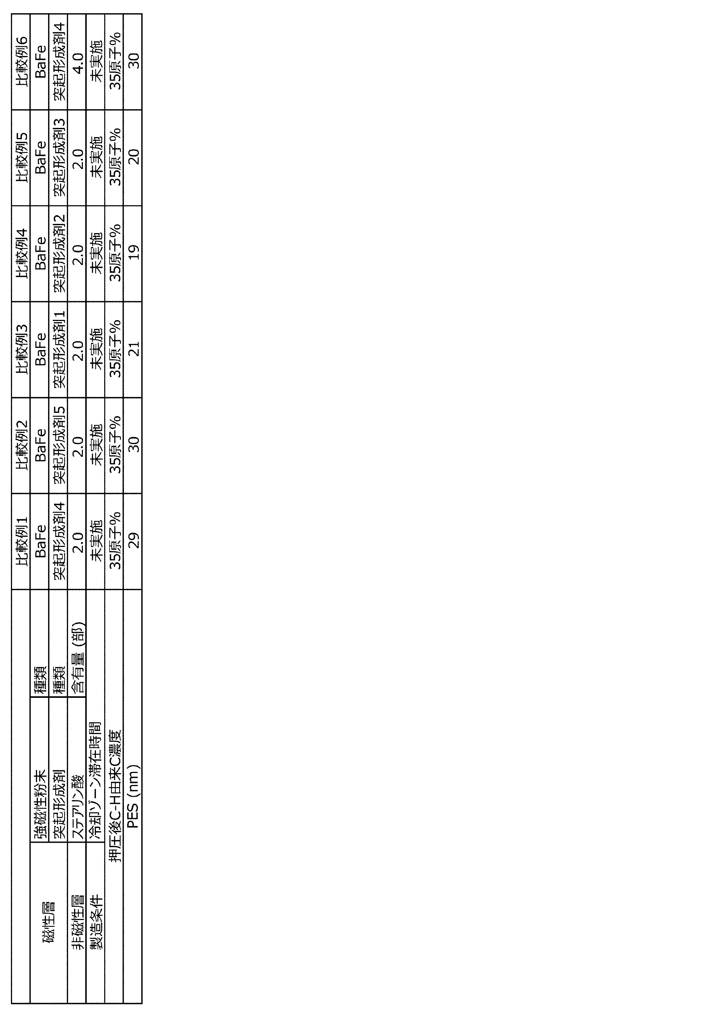
(i)ワイドスキャン測定
磁気テープの磁性層表面においてESCA装置によりワイドスキャン測定(測定条件:表2参照)を行い、検出された元素の種類を調べた(定性分析)。
(I) Wide scan measurement Wide scan measurement (measurement conditions: see Table 2) was performed on the surface of the magnetic layer of the magnetic tape with an ESCA device, and the types of detected elements were investigated (qualitative analysis).
(ii)ナロースキャン測定
上記(i)で検出された全元素について、ナロースキャン測定(測定条件:表3参照)を行った。装置付属のデータ処理用ソフトウエア(Vision2.2.6)を用いて、各元素のピーク面積から検出された各元素の原子濃度(単位:原子%)を算出した。ここでC濃度も算出した。
(Ii) Narrow scan measurement Narrow scan measurement (measurement conditions: see Table 3) was performed on all the elements detected in (i) above. Using the data processing software (Vision 2.2.6) attached to the device, the atomic concentration (unit: atomic%) of each element detected from the peak area of each element was calculated. Here, the C concentration was also calculated.
(iii)C1sスペクトルの取得
表4に記載の測定条件にてC1sスペクトルを取得した。取得したC1sスペクトルについて、装置付属のデータ処理用ソフトウエア(Vision2.2.6)を用いて試料帯電に起因するシフト(物理シフト)の補正を行った後、同ソフトウエアを用いてC1sスペクトルのフィッティング処理(ピーク分離)を実施した。ピーク分離にはガウス−ローレンツ複合関数(ガウス成分70%、ローレンツ成分30%)を用い、非線形最小二乗法によりC1sスペクトルのフィッティングを行い、C1sスペクトルに占めるC−Hピークの割合(ピーク面積率)を算出した。算出されたC−Hピーク面積率を、上記(ii)で求めたC濃度に掛けることにより、C−H由来C濃度を算出した。
(Iii) Acquisition of C1s spectrum A C1s spectrum was acquired under the measurement conditions shown in Table 4. The acquired C1s spectrum is corrected for the shift (physical shift) caused by sample charging using the data processing software (Vision 2.2.6) attached to the device, and then the C1s spectrum is calculated using the same software. A fitting process (peak separation) was performed. A Gauss-Lorentz composite function (Gaussian component 70%, Lorenz component 30%) is used for peak separation, and the C1s spectrum is fitted by the nonlinear least squares method, and the ratio of the CH peak to the C1s spectrum (peak area ratio). Was calculated. The CH-derived C concentration was calculated by multiplying the calculated CH peak area ratio by the C concentration obtained in (ii) above.
以上の処理を上記測定用試料の磁性層表面の異なる位置において3回行い、得られた値の算術平均をC−H由来C濃度とした。 The above treatment was performed three times at different positions on the surface of the magnetic layer of the measurement sample, and the arithmetic mean of the obtained values was taken as the C concentration derived from CH.
(2)70atmの圧力での押圧後の走行安定性の評価
実施例および比較例の各磁気テープについて、上記(1)での押圧後、以下の方法によりPES(Position Error Signal)を求めた。
サーボパターンの形成に用いたサーボライター上のベリファイ(verify)ヘッドでサーボパターンを読み取った。ベリファイヘッドは、磁気テープに形成されたサーボパターンの品質を確認するための読取用磁気ヘッドであり、公知の磁気テープ装置(ドライブ)の磁気ヘッドと同様に、サーボパターンの位置(磁気テープの幅方向の位置)に対応した位置に読取用の素子が配置されている。
ベリファイヘッドには、ベリファイヘッドでサーボパターンを読み取って得た電気信号から、サーボシステムにおけるヘッド位置決め精度をPESとして演算する公知のPES演算回路が接続されている。PES演算回路は、入力された電気信号(パルス信号)から磁気テープの幅方向への変位を随時計算し、この変位の時間的変化情報(信号)に対してハイパスフィルタ(カットオフ:500cycles/m)を適用した値を、PESとして算出した。PESは走行安定性の指標とすることができ、上記で算出されたPESが18nm以下であれば、走行安定性に優れると評価することができる。
(2) Evaluation of running stability after pressing at a pressure of 70 atm For each of the magnetic tapes of Examples and Comparative Examples, PES (Position Error Signal) was determined by the following method after pressing in (1) above.
The servo pattern was read by the verify head on the servo writer used to form the servo pattern. The verify head is a reading magnetic head for confirming the quality of the servo pattern formed on the magnetic tape, and like the magnetic head of a known magnetic tape device (drive), the position of the servo pattern (width of the magnetic tape). The reading element is arranged at a position corresponding to the position in the direction).
A known PES calculation circuit that calculates the head positioning accuracy in the servo system as PES from the electric signal obtained by reading the servo pattern with the verify head is connected to the verify head. The PES calculation circuit calculates the displacement of the magnetic tape in the width direction from the input electric signal (pulse signal) at any time, and applies a high-pass filter (cutoff: 500 cycles / m) to the temporal change information (signal) of this displacement. ) Was applied, and the value was calculated as PES. The PES can be used as an index of running stability, and if the PES calculated above is 18 nm or less, it can be evaluated that the running stability is excellent.
以上の結果を、表5(表5−1〜表5−7)に示す。 The above results are shown in Table 5 (Tables 5-1 to 5-7).
表5に示す結果から、実施例の磁気テープはいずれも、70atmの圧力での押圧後、即ち、長期保管後に相当する状態において、優れた走行安定性を示したことが確認できる。このような磁気テープであれば、アクセス頻度の低い情報が記録された後に磁気テープカートリッジ内で長期間リールに巻き取られた状態で収容された後でも、磁気記録再生装置内で安定走行可能であり、アーカイブ用記録媒体として好適である。 From the results shown in Table 5, it can be confirmed that all of the magnetic tapes of the examples showed excellent running stability after being pressed at a pressure of 70 atm, that is, in a state corresponding to after long-term storage. With such a magnetic tape, stable running is possible in the magnetic recording / playback device even after the information with low access frequency is recorded and then stored in the magnetic tape cartridge in a state of being wound on a reel for a long period of time. Yes, it is suitable as a recording medium for archiving.
本発明の一態様は、データストレージ用途において有用である。 One aspect of the present invention is useful in data storage applications.
Claims (15)
前記非磁性支持体と前記磁性層との間に、非磁性粉末を含む非磁性層を有し、
前記非磁性支持体の前記磁性層を有する表面側とは反対の表面側に、非磁性粉末を含むバックコート層を有し、
前記強磁性粉末は、六方晶フェライト粉末およびε−酸化鉄粉末からなる群から選ばれる強磁性粉末であり、
前記非磁性支持体上の磁性層側の部分に、脂肪酸および脂肪酸アミドからなる群から選ばれる成分の一種以上を含み、
前記磁性層を70atmの圧力で押圧した後に該磁性層の表面において光電子取り出し角10度で行われるX線光電子分光分析により得られるC1sスペクトルにおけるC−Hピーク面積率から算出されるC−H由来C濃度が45原子%以上である磁気記録媒体。 A magnetic recording medium having a magnetic layer containing ferromagnetic powder on a non-magnetic support.
A non-magnetic layer containing non-magnetic powder is provided between the non-magnetic support and the magnetic layer.
A backcoat layer containing non-magnetic powder is provided on the surface side of the non-magnetic support opposite to the surface side having the magnetic layer.
The ferromagnetic powder is a ferromagnetic powder selected from the group consisting of hexagonal ferrite powder and ε-iron oxide powder.
The portion on the non-magnetic support on the magnetic layer side contains one or more components selected from the group consisting of fatty acids and fatty acid amides.
Derived from CH calculated from the CH peak area ratio in the C1s spectrum obtained by X-ray photoelectron spectroscopy performed on the surface of the magnetic layer at a photoelectron extraction angle of 10 degrees after pressing the magnetic layer with a pressure of 70 atm. A magnetic recording medium having a C concentration of 45 atomic% or more.
磁気ヘッドと、
を含む磁気記録再生装置。 The magnetic recording medium according to any one of claims 1 to 14,
With a magnetic head
Magnetic recording / playback device including.
Priority Applications (2)
| Application Number | Priority Date | Filing Date | Title |
|---|---|---|---|
| JP2020122790A JP6858905B2 (en) | 2020-07-17 | 2020-07-17 | Magnetic recording medium and magnetic recording / playback device |
| JP2020181395A JP7299205B2 (en) | 2020-07-17 | 2020-10-29 | Magnetic recording medium and magnetic recording/reproducing device |
Applications Claiming Priority (1)
| Application Number | Priority Date | Filing Date | Title |
|---|---|---|---|
| JP2020122790A JP6858905B2 (en) | 2020-07-17 | 2020-07-17 | Magnetic recording medium and magnetic recording / playback device |
Related Parent Applications (1)
| Application Number | Title | Priority Date | Filing Date |
|---|---|---|---|
| JP2019170512A Division JP6778805B1 (en) | 2019-09-19 | 2019-09-19 | Magnetic recording medium and magnetic recording / playback device |
Related Child Applications (1)
| Application Number | Title | Priority Date | Filing Date |
|---|---|---|---|
| JP2020181395A Division JP7299205B2 (en) | 2020-07-17 | 2020-10-29 | Magnetic recording medium and magnetic recording/reproducing device |
Publications (2)
| Publication Number | Publication Date |
|---|---|
| JP2021047972A JP2021047972A (en) | 2021-03-25 |
| JP6858905B2 true JP6858905B2 (en) | 2021-04-14 |
Family
ID=74878635
Family Applications (1)
| Application Number | Title | Priority Date | Filing Date |
|---|---|---|---|
| JP2020122790A Active JP6858905B2 (en) | 2020-07-17 | 2020-07-17 | Magnetic recording medium and magnetic recording / playback device |
Country Status (1)
| Country | Link |
|---|---|
| JP (1) | JP6858905B2 (en) |
Family Cites Families (5)
| Publication number | Priority date | Publication date | Assignee | Title |
|---|---|---|---|---|
| JP6378166B2 (en) * | 2014-12-26 | 2018-08-22 | 富士フイルム株式会社 | Magnetic tape and manufacturing method thereof |
| JP6556096B2 (en) * | 2016-06-10 | 2019-08-07 | 富士フイルム株式会社 | Magnetic tape and magnetic tape device |
| JP6723296B2 (en) * | 2017-07-19 | 2020-07-15 | 富士フイルム株式会社 | Magnetic recording medium |
| JP7091264B2 (en) * | 2019-01-31 | 2022-06-27 | 富士フイルム株式会社 | Magnetic tapes, magnetic tape cartridges and magnetic tape devices |
| JP6778805B1 (en) * | 2019-09-19 | 2020-11-04 | 富士フイルム株式会社 | Magnetic recording medium and magnetic recording / playback device |
-
2020
- 2020-07-17 JP JP2020122790A patent/JP6858905B2/en active Active
Also Published As
| Publication number | Publication date |
|---|---|
| JP2021047972A (en) | 2021-03-25 |
Similar Documents
| Publication | Publication Date | Title |
|---|---|---|
| JP6778805B1 (en) | Magnetic recording medium and magnetic recording / playback device | |
| JP7427121B2 (en) | Magnetic tape cartridges and magnetic tape devices | |
| JP6778803B1 (en) | Magnetic recording medium and magnetic recording / playback device | |
| JP6778804B1 (en) | Magnetic recording medium and magnetic recording / playback device | |
| JP2020140758A (en) | Magnetic recording medium and magnetic recording / playback device | |
| JP6852218B2 (en) | Magnetic tape and magnetic recording / playback device | |
| JP7091264B2 (en) | Magnetic tapes, magnetic tape cartridges and magnetic tape devices | |
| JP7425909B2 (en) | Magnetic tape, magnetic tape cartridges and magnetic tape devices | |
| JP6788084B1 (en) | Magnetic recording medium and magnetic recording / playback device | |
| JP7112979B2 (en) | Magnetic recording medium and magnetic recording/reproducing device | |
| JP2021047956A (en) | Magnetic recording medium and magnetic recording / playback device | |
| WO2022025155A1 (en) | Magnetic tape, magnetic tape cartridge, and magnetic tape device | |
| JP6893952B2 (en) | Magnetic recording medium and magnetic recording / playback device | |
| JP6858905B2 (en) | Magnetic recording medium and magnetic recording / playback device | |
| JP7432785B2 (en) | Magnetic recording media and magnetic recording/reproducing devices | |
| JP2021047975A (en) | Magnetic recording medium and magnetic recording / playback device | |
| JP7299205B2 (en) | Magnetic recording medium and magnetic recording/reproducing device | |
| JP6909907B2 (en) | Magnetic recording medium and magnetic recording / playback device | |
| JP6884256B2 (en) | Magnetic recording medium and magnetic recording / playback device | |
| JP6909908B2 (en) | Magnetic recording medium and magnetic recording / playback device | |
| JP7691878B2 (en) | Magnetic tape, magnetic tape cartridge and magnetic recording/reproducing device | |
| JP2021047977A (en) | Magnetic recording medium and magnetic recording and reproducing device | |
| JP2021047978A (en) | Magnetic recording medium and magnetic recording and reproducing device | |
| JP2021034072A (en) | Magnetic tape, magnetic tape cartridge and magnetic recording/reproducing device | |
| JP2022027074A (en) | Magnetic recording medium, magnetic tape cartridge and magnetic recording / playback device |
Legal Events
| Date | Code | Title | Description |
|---|---|---|---|
| A521 | Request for written amendment filed |
Free format text: JAPANESE INTERMEDIATE CODE: A523 Effective date: 20201029 |
|
| A621 | Written request for application examination |
Free format text: JAPANESE INTERMEDIATE CODE: A621 Effective date: 20201029 |
|
| A871 | Explanation of circumstances concerning accelerated examination |
Free format text: JAPANESE INTERMEDIATE CODE: A871 Effective date: 20210219 |
|
| A975 | Report on accelerated examination |
Free format text: JAPANESE INTERMEDIATE CODE: A971005 Effective date: 20210309 |
|
| TRDD | Decision of grant or rejection written | ||
| A01 | Written decision to grant a patent or to grant a registration (utility model) |
Free format text: JAPANESE INTERMEDIATE CODE: A01 Effective date: 20210316 |
|
| A61 | First payment of annual fees (during grant procedure) |
Free format text: JAPANESE INTERMEDIATE CODE: A61 Effective date: 20210324 |
|
| R150 | Certificate of patent or registration of utility model |
Ref document number: 6858905 Country of ref document: JP Free format text: JAPANESE INTERMEDIATE CODE: R150 |
|
| R250 | Receipt of annual fees |
Free format text: JAPANESE INTERMEDIATE CODE: R250 |
|
| R250 | Receipt of annual fees |
Free format text: JAPANESE INTERMEDIATE CODE: R250 |