JP6858653B2 - Liquid transfer device and cell culture device using it - Google Patents
Liquid transfer device and cell culture device using it Download PDFInfo
- Publication number
- JP6858653B2 JP6858653B2 JP2017118867A JP2017118867A JP6858653B2 JP 6858653 B2 JP6858653 B2 JP 6858653B2 JP 2017118867 A JP2017118867 A JP 2017118867A JP 2017118867 A JP2017118867 A JP 2017118867A JP 6858653 B2 JP6858653 B2 JP 6858653B2
- Authority
- JP
- Japan
- Prior art keywords
- liquid
- container
- liquid feeding
- pipe
- tube
- Prior art date
- Legal status (The legal status is an assumption and is not a legal conclusion. Google has not performed a legal analysis and makes no representation as to the accuracy of the status listed.)
- Active
Links
Images


Classifications
-
- C—CHEMISTRY; METALLURGY
- C12—BIOCHEMISTRY; BEER; SPIRITS; WINE; VINEGAR; MICROBIOLOGY; ENZYMOLOGY; MUTATION OR GENETIC ENGINEERING
- C12M—APPARATUS FOR ENZYMOLOGY OR MICROBIOLOGY; APPARATUS FOR CULTURING MICROORGANISMS FOR PRODUCING BIOMASS, FOR GROWING CELLS OR FOR OBTAINING FERMENTATION OR METABOLIC PRODUCTS, i.e. BIOREACTORS OR FERMENTERS
- C12M29/00—Means for introduction, extraction or recirculation of materials, e.g. pumps
- C12M29/26—Conditioning fluids entering or exiting the reaction vessel
-
- C—CHEMISTRY; METALLURGY
- C12—BIOCHEMISTRY; BEER; SPIRITS; WINE; VINEGAR; MICROBIOLOGY; ENZYMOLOGY; MUTATION OR GENETIC ENGINEERING
- C12M—APPARATUS FOR ENZYMOLOGY OR MICROBIOLOGY; APPARATUS FOR CULTURING MICROORGANISMS FOR PRODUCING BIOMASS, FOR GROWING CELLS OR FOR OBTAINING FERMENTATION OR METABOLIC PRODUCTS, i.e. BIOREACTORS OR FERMENTERS
- C12M41/00—Means for regulation, monitoring, measurement or control, e.g. flow regulation
- C12M41/48—Automatic or computerized control
-
- C—CHEMISTRY; METALLURGY
- C12—BIOCHEMISTRY; BEER; SPIRITS; WINE; VINEGAR; MICROBIOLOGY; ENZYMOLOGY; MUTATION OR GENETIC ENGINEERING
- C12M—APPARATUS FOR ENZYMOLOGY OR MICROBIOLOGY; APPARATUS FOR CULTURING MICROORGANISMS FOR PRODUCING BIOMASS, FOR GROWING CELLS OR FOR OBTAINING FERMENTATION OR METABOLIC PRODUCTS, i.e. BIOREACTORS OR FERMENTERS
- C12M21/00—Bioreactors or fermenters specially adapted for specific uses
- C12M21/08—Bioreactors or fermenters specially adapted for specific uses for producing artificial tissue or for ex-vivo cultivation of tissue
-
- C—CHEMISTRY; METALLURGY
- C12—BIOCHEMISTRY; BEER; SPIRITS; WINE; VINEGAR; MICROBIOLOGY; ENZYMOLOGY; MUTATION OR GENETIC ENGINEERING
- C12M—APPARATUS FOR ENZYMOLOGY OR MICROBIOLOGY; APPARATUS FOR CULTURING MICROORGANISMS FOR PRODUCING BIOMASS, FOR GROWING CELLS OR FOR OBTAINING FERMENTATION OR METABOLIC PRODUCTS, i.e. BIOREACTORS OR FERMENTERS
- C12M23/00—Constructional details, e.g. recesses, hinges
- C12M23/20—Material Coatings
-
- C—CHEMISTRY; METALLURGY
- C12—BIOCHEMISTRY; BEER; SPIRITS; WINE; VINEGAR; MICROBIOLOGY; ENZYMOLOGY; MUTATION OR GENETIC ENGINEERING
- C12M—APPARATUS FOR ENZYMOLOGY OR MICROBIOLOGY; APPARATUS FOR CULTURING MICROORGANISMS FOR PRODUCING BIOMASS, FOR GROWING CELLS OR FOR OBTAINING FERMENTATION OR METABOLIC PRODUCTS, i.e. BIOREACTORS OR FERMENTERS
- C12M25/00—Means for supporting, enclosing or fixing the microorganisms, e.g. immunocoatings
- C12M25/14—Scaffolds; Matrices
-
- C—CHEMISTRY; METALLURGY
- C12—BIOCHEMISTRY; BEER; SPIRITS; WINE; VINEGAR; MICROBIOLOGY; ENZYMOLOGY; MUTATION OR GENETIC ENGINEERING
- C12M—APPARATUS FOR ENZYMOLOGY OR MICROBIOLOGY; APPARATUS FOR CULTURING MICROORGANISMS FOR PRODUCING BIOMASS, FOR GROWING CELLS OR FOR OBTAINING FERMENTATION OR METABOLIC PRODUCTS, i.e. BIOREACTORS OR FERMENTERS
- C12M29/00—Means for introduction, extraction or recirculation of materials, e.g. pumps
-
- C—CHEMISTRY; METALLURGY
- C12—BIOCHEMISTRY; BEER; SPIRITS; WINE; VINEGAR; MICROBIOLOGY; ENZYMOLOGY; MUTATION OR GENETIC ENGINEERING
- C12M—APPARATUS FOR ENZYMOLOGY OR MICROBIOLOGY; APPARATUS FOR CULTURING MICROORGANISMS FOR PRODUCING BIOMASS, FOR GROWING CELLS OR FOR OBTAINING FERMENTATION OR METABOLIC PRODUCTS, i.e. BIOREACTORS OR FERMENTERS
- C12M41/00—Means for regulation, monitoring, measurement or control, e.g. flow regulation
- C12M41/44—Means for regulation, monitoring, measurement or control, e.g. flow regulation of volume or liquid level
Description
本発明は、送液装置およびそれを用いた細胞培養装置に関する。 The present invention relates to a liquid feeding device and a cell culture device using the same.
近年、細胞培養を自動化できる細胞培養装置が開発されてきた。細胞培養装置においては、培養容器の蓋を開閉する操作が不要な閉鎖系培養容器を用いることで、生物学的汚染リスクが低減できる。 In recent years, cell culture devices capable of automating cell culture have been developed. In the cell culture apparatus, the risk of biological contamination can be reduced by using a closed culture vessel that does not require an operation of opening and closing the lid of the culture vessel.
培養細胞によっては、細胞の培養容器への接着性を高めるため、細胞培養を始める前に、足場材でコーティングする必要がある。自動培養装置では、足場材溶液の分注器を機械化し、手操作と同様に足場材溶液の分取と移送の動作を連動して足場材添加を行う方法がある(例えば、特許文献1参照)。また、分注操作にポンプを使用し、足場材溶液ボトルと培養皿を使い捨てのチューブで接続し、ポンプによって一定量の足場材溶液を送液する方法がある(例えば、特許文献2、3参照)。 Some cultured cells need to be coated with a scaffold material before starting cell culture in order to improve the adhesion of the cells to the culture vessel. In the automatic culture apparatus, there is a method in which the scaffolding material dispenser is mechanized and the scaffolding material is added by interlocking the operations of the scaffolding material solution separation and transfer in the same manner as the manual operation (see, for example, Patent Document 1). ). Further, there is a method in which a pump is used for the dispensing operation, the scaffolding material solution bottle and the culture dish are connected by a disposable tube, and a fixed amount of the scaffolding material solution is sent by the pump (see, for example, Patent Documents 2 and 3). ).
本発明の目的は、新規な送液装置およびそれを用いた細胞培養装置を提供することである。 An object of the present invention is to provide a novel liquid feeding device and a cell culture device using the same.
本発明の一実施態様は、第1の液体を含む第1の容器と、第2の液体を含む第2の容器と、第1の液体及び第2の液体を入れるための第3の容器と、第1の液体及び第2の液体を排出するための第4の容器と、第3の液体を含む第5の容器と、第1の液体を送液するための第1の送液管と、第2の液体を送液するための第2の送液管と、第1の送液管及び第2の送液管に接続し、第1の送液管中の第1の液体及び第2の送液管中の第2の液体を第3の容器に送液するための第3の送液管と、第3の送液管に設けられ、第3の送液管での送液を制御するための第1の送液ポンプと、第3の容器中の第1の液体を排出し、第3の液体を第3の容器に送液するための第4の送液管と、第4の送液管に接続し、第5の容器中の第3の液体を第4の送液管を通じて第3の容器に送液する第5の送液管と、第4の送液管に接続し、第3の容器中の第1の液体を第4の送液管を通じて第4の容器に排出する第6の送液管と、第4の送液管に設けられ、第4の送液管での送液を制御するための第2の送液ポンプと、を備える、送液装置である。第1の送液管、第2の送液管、第5の送液管、および第6の送液管のそれぞれに弁が設けられていてもよい。 One embodiment of the present invention comprises a first container containing a first liquid, a second container containing a second liquid, and a third container for containing the first liquid and the second liquid. , A fourth container for discharging the first liquid and the second liquid, a fifth container containing the third liquid, and a first liquid feeding tube for feeding the first liquid. , The first liquid and the first liquid in the first liquid feed pipe connected to the second liquid feed pipe for feeding the second liquid, the first liquid feed pipe and the second liquid feed pipe. A third liquid feed pipe for feeding the second liquid in the second liquid feed pipe to the third container, and a liquid feed pipe provided in the third liquid feed pipe and in the third liquid feed pipe. A first liquid feeding pump for controlling the above, a fourth liquid feeding pipe for discharging the first liquid in the third container, and sending the third liquid to the third container, A fifth liquid feed pipe connected to the fourth liquid feed pipe and the third liquid in the fifth container is fed to the third container through the fourth liquid feed pipe, and a fourth liquid feed pipe. A sixth liquid feed pipe, which is connected to and discharges the first liquid in the third container to the fourth container through the fourth liquid feed pipe, and a fourth liquid feed pipe provided in the fourth liquid feed pipe. It is a liquid feeding device including a second liquid feeding pump for controlling liquid feeding in a liquid feeding pipe. Valves may be provided in each of the first liquid feed pipe, the second liquid feed pipe, the fifth liquid feed pipe, and the sixth liquid feed pipe.
本発明の他の実施態様は、細胞培養用培地を含む第1の容器と、細胞懸濁液を含む第2の容器と、細胞を培養するための第3の容器と、培養後の廃液を捨てるための第4の容器と、細胞の足場材を含む足場材溶液を含む第5の容器と、第1の容器中の前記細胞培養用培地を送液するための第1の送液管と、第2の容器中の前記細胞懸濁液を送液するための第2の送液管と、第1の送液管及び第2の送液管に接続し、第1の送液管中の前記細胞培養用培地及び第2の送液管中の前記細胞懸濁液を第3の容器に送液するための第3の送液
管と、第3の送液管に設けられ、第3の送液管での送液を制御するための第1の送液ポンプと、第3の容器中の前記細胞培養用培地を排出し、前記足場材溶液を第3の容器に送液するための第4の送液管と、第4の送液管に接続し、第5の容器中の前記足場材溶液を第4の送液管を通じて第3の容器に送液する第5の送液管と、第4の送液管に接続し、第3の容器中の前記細胞培養用培地を第4の送液管を通じて第4の容器に排出する第6の送液管と、第4の送液管に設けられ、第4の送液管での送液を制御するための第2の送液ポンプと、を備える、送液装置である。第1の送液管、第2の送液管、第5の送液管、および第6の送液管のそれぞれに弁が設けられていてもよい。前記細胞が幹細胞であってもよい。前記足場材が、フィブロネクチン、コラーゲン、アルブミン、ラミニン、ポリリジン、ポリオルニチン、またはゼラチンを含んでもよい。
Another embodiment of the present invention comprises a first container containing a cell culture medium, a second container containing a cell suspension, a third container for culturing cells, and a waste liquid after culturing. A fourth container for discarding, a fifth container containing a scaffolding material solution containing a cell scaffolding material, and a first liquid feeding tube for feeding the cell culture medium in the first container. , Connected to the second liquid feeding tube for feeding the cell suspension in the second container, the first liquid feeding tube and the second liquid feeding tube, and in the first liquid feeding tube. A third liquid feeding tube for feeding the cell culture medium and the cell suspension in the second liquid feeding tube to a third container, and a third liquid feeding tube provided in the third liquid feeding tube. The first liquid feeding pump for controlling the liquid feeding in the liquid feeding pipe 3 and the cell culture medium in the third container are discharged, and the scaffolding material solution is sent to the third container. A fifth delivery pipe that is connected to a fourth liquid delivery pipe for the purpose and feeds the scaffolding material solution in the fifth container to the third container through the fourth liquid supply pipe. A sixth liquid pipe, which is connected to the liquid pipe and the fourth liquid pipe, and discharges the cell culture medium in the third container to the fourth container through the fourth liquid pipe, and a fourth liquid pipe. It is a liquid feeding device provided in the liquid feeding pipe of No. 1 and provided with a second liquid feeding pump for controlling the liquid feeding in the fourth liquid feeding pipe. Valves may be provided in each of the first liquid feed pipe, the second liquid feed pipe, the fifth liquid feed pipe, and the sixth liquid feed pipe. The cell may be a stem cell. The scaffolding material may include fibronectin, collagen, albumin, laminin, polylysine, polyornithine, or gelatin.
本発明のさらなる実施態様は、上記いずれかの送液装置を1または複数備える、細胞培養装置である。 A further embodiment of the present invention is a cell culture device including one or more of the above liquid feeding devices.
本発明によって、新規な送液装置およびそれを用いた細胞培養装置を提供できるようになった。 INDUSTRIAL APPLICABILITY According to the present invention, it has become possible to provide a novel liquid feeding device and a cell culture device using the same.
以下、添付図面を参照して本発明の種々の実施形態について説明する。ただし、これらの実施形態は本発明を実現するための例示に過ぎず、本発明の技術的範囲を限定するものではない。なお、各図において共通の構成については同一の参照番号が付されている。 Hereinafter, various embodiments of the present invention will be described with reference to the accompanying drawings. However, these embodiments are merely examples for realizing the present invention, and do not limit the technical scope of the present invention. The same reference number is assigned to the common configuration in each figure.
<送液装置 I>
以下に、送液装置Iの構成例を示す。
<Liquid feeder I>
A configuration example of the liquid feeding device I is shown below.
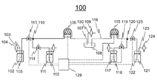
送液装置100は、第1の液体を含む第1の容器102と、第2の液体を含む第2の容器111と、第1の液体及び第2の液体を含む第3の容器108を有する。
The
第1の容器102、第2の容器111、第3の容器108は、その目的を考慮し、当業者の技術常識によって容易に作製可能である。それぞれ、外気に開放している気圧調節管103を有し、容器内の気相に末端を有する。第3の容器108も、その目的を考慮し、当業者の技術常識によって容易に作製可能である。第3の容器108は外気に開放している気圧調節管130を有し、容器内の気相に末端を有する。
The
送液装置100は、第1の容器102中の第1の液体を送液するための第1の送液管105と、第2の容器111中の第2の液体を送液するための第2の送液管112と、第1の送液管105及び第2の送液管112に接続し、第1の送液管105中の第1の液体及び第2の送液管112中の第2の液体を第3の容器108に送液するための第3の送液管107を有する。第3の送液管107は、第1の送液ポンプ106を有し、第3の送液管107内の送液を調節する。それぞれの送液管は、当業者の技術常識によって容易に作製可能である。例えば、第1の送液管105と第3の送液管107、または第2の送液管112と第3の送液管107を1本の管とし、それぞれ第2の送液管112、または第1の送液管105を接続させるような構造であってもよい。第1の送液管105及び第2の送
液管112はそれぞれ第1の弁113及び第2の弁114を有し、それぞれ開閉を行うことにより、送液の有り・無しを切り替えることができる。
The
また、送液装置100は、第3の容器108中の第1の液体を捨てるための第4の容器121と、第3の溶液を含む第5の容器117を有する。第4の容器121や第5の容器117は、目的を考慮し、当業者の技術常識によって容易に作製可能である。それぞれ、外気に開放している気圧調節管123を有し、容器内の気相に末端を有する。第3の溶液は、粘性があるものが好ましい。それによって、第3の溶液が第1〜第3の送液管を汚すことがない。
Further, the
送液装置100は、さらに、第3の容器中108の第1の液体を排出し、第3の溶液を第3の容器108に送液するための第4の送液管116と、第4の送液管116に接続し、第5の容器117中の第3の溶液を第4の送液管116を通じて第3の容器108に送液する第5の送液管118と、第4の送液管116に接続し、第3の容器108中の第1の液体を第4の送液管116を通じて第4の容器121に排出する第6の送液管122と、を備える。第4の送液管116は、第2の送液ポンプ115を有し、第4の送液管116内の送液を制御する。それぞれの送液管は、当業者の技術常識によって容易に作製可能である。例えば、第4の送液管116と第5の送液管118、または第4の送液管116と第6の送液管122を1本の管とし、それぞれ第6の送液管122、または第5の送液管118を接続部120で接続させるような構造であってもよい。第5の送液管118及び第6の送液管122はそれぞれ第3の弁119及び第4の弁125を有し、それぞれ開閉を行うことにより、送液の有り・無しを切り替えることができる。
The
なお、制御部129を設け、ポンプの作動や弁の開閉などを自動的に制御できるようにすることが好ましい。
It is preferable to provide a
このように、第1〜第3の送液管と、第4および第5の送液管とを分けることによって、第3の容器108に必要な第3の溶液によって、第1〜第3の送液管が汚染することがない。しかも、第3の溶液の送液を、第1の液体を捨てることに使用されるのと同じポンプを用いることにより、装置構成が単純化される。 In this way, by separating the first to third liquid feed pipes and the fourth and fifth liquid feed pipes, the third solution required for the third container 108 can be used to obtain the first to third liquid pipes. The liquid feed pipe is not contaminated. Moreover, the apparatus configuration is simplified by using the same pump used to dispose of the first liquid for feeding the third solution.
<送液装置 II>
送液装置IIを細胞培養に用いる場合について、図2の送液装置を参照しながら、以下に詳細を記載する。
<Liquid feeder II>
The case where the liquid feeding device II is used for cell culture will be described in detail below with reference to the liquid feeding device of FIG.
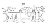
送液装置200は、細胞培養用培地を含む培地容器202と、細胞懸濁液を含む細胞容器211と、細胞を培養するための培養容器208を有する。
The
培地容器202や細胞容器211は、当業者の技術常識によって容易に作製可能である。それぞれ、外気に開放している気圧調節管203を有し、容器内の気相に末端を有する。気圧調節管203はフィルター204を有し、培地容器202や細胞容器211に流入する外気を滅菌する。従って、例えばフィルター204は、0.22μmサイズの孔径を有する滅菌用フィルターを用いることができる。細胞培養用培地は、培養する細胞にて適したものであれば、当業者が適切に選択することができる。細胞懸濁液は、培養目的の細胞を培地またはPBSなどの緩衝液に適当な濃度で懸濁した液体である。
The
培養容器208は特に限定されないが、培養皿や培養ボトルであることが好ましい。培養容器208の底面は、コーティングされていないものが好ましく、例えば市販の細菌培養用プラスティックディッシュを用いることができる。培養容器208は外気に開放している気圧調節管230を有し、容器内の気相に末端を有する。気圧調節管230はフィル
ター209を有し、培養容器208に流入する外気を滅菌する。従って、例えばフィルター209は、0.22μmサイズの孔径を有する滅菌用フィルターを用いることができる。
The
送液装置200は、培地容器202中の細胞培養用培地を送液するための培地送液管205と、細胞容器211中の細胞懸濁液を送液するための細胞懸濁液送液管212と、培地送液管205及び細胞懸濁液送液管212に接続部210において接続し、培地送液管205中の細胞培養用培地及び細胞懸濁液送液管212中の細胞懸濁液を培養容器208に送液するための培養物送液管207を有する。培養物送液管207は、第1の送液ポンプ206を有し、培養物送液管207内の送液を調節する。それぞれの送液管は、当業者の技術常識によって容易に作製可能である。例えば、培地送液管205と培養物送液管207、または細胞懸濁液送液管212と培養物送液管207を1本の管とし、それぞれ細胞懸濁液送液管212、または培地送液管205を接続部210で接続させるような構造であってもよい。培地送液管205及び細胞懸濁液送液管212はそれぞれ培地送液弁213及び細胞懸濁液送液弁214を有し、それぞれ開閉を行うことにより、送液の有り・無しを切り替えることができる。
The
送液装置200は、さらに、外気と接続している2本の気体導入管231、241を有し、それぞれ接続部226、236で培養物送液管207または両方向送液管216に接続する。気体導入管231、241はフィルター227、237を有し、送液装置200に導入する外気を滅菌する。従って、例えばフィルター227、237は、0.22μmサイズの孔径を有する滅菌用フィルターを用いることができる。また、気体導入管231、241は外気流入弁228、238を有し、外気の流入の有り・無しを調節する。これらの気体導入管231、241は、複数の培養容器208にそれぞれ培地容器202からの培地または足場材溶液容器217からの足場材を注入する場合、培養容器208の交換前に外気流入弁228、238を開け、一旦培養物送液管207または両方向送液管216中の培地または足場材を空にするために用いる。
The
また、送液装置200は、培養後の廃液を捨てるための廃液容器221と、細胞の足場材を含む足場材溶液を含む足場材溶液容器217を有する。廃液容器221や足場材溶液容器217は、当業者の技術常識によって容易に作製可能である。それぞれ、外気に開放している気圧調節管223を有し、容器内の気相に末端を有する。気圧調節管223はフィルター224を有し、廃液容器221や足場材溶液容器217に流入する外気を滅菌する。従って、例えばフィルター224は、0.22μmサイズの孔径を有する滅菌用フィルターを用いることができる。足場材は、培養容器208の底面をコーティングし、培養細胞の接着を促進するものであって、培養する細胞に適合するものを選択すればよい。例えば、フィブロネクチン、コラーゲン、アルブミン、ラミニン、ポリリジン、ポリオルニチン、またはゼラチンを含んでもよい。
Further, the
送液装置200は、さらに、培養容器208中の細胞培養用培地を排出し、足場材溶液を培養容器208に送液するための両方向送液管216と、両方向送液管216に接続し、足場材溶液容器217中の足場材溶液を両方向送液管216を通じて培養容器208に送液する足場材溶液送液管218と、両方向送液管216に接続し、培養容器208中の細胞培養用培地を両方向送液管216を通じて廃液容器221に排出する廃液送液管222と、を備える。両方向送液管216は、第2の送液ポンプ215を有し、両方向送液管216内の送液を制御する。それぞれの送液管は、当業者の技術常識によって容易に作製可能である。例えば、両方向送液管216と足場材溶液送液管218、または両方向送液管216と廃液送液管222を1本の管とし、それぞれ廃液送液管222、または足場材溶液送液管218を接続部220で接続させるような構造であってもよい。足場材溶液送液管218及び廃液送液管222はそれぞれ足場材溶液送液弁219及び廃液送液弁225を有し、それぞれ開閉を行うことにより、送液の有り・無しを切り替えることができる。
The
各容器及び各送液管はそれぞれ気密に保つことができるような構造とするのが好ましく、それによって、装置内部を滅菌状態に維持することができる。また、制御部229を設け、ポンプの作動や弁の開閉などを自動的に制御できるようにすることが好ましい。
It is preferable that each container and each liquid feeding tube have a structure that can be kept airtight, whereby the inside of the device can be maintained in a sterilized state. Further, it is preferable to provide a
このように、足場材溶液送液管218と細胞懸濁液送液管212を分けることによって、送液処理の間に、足場材溶液が通過した後を細胞懸濁液が通過することがなくなり、細胞懸濁液中の細胞が、装置内に付着した足場材溶液によって不適当な場所にトラップされることがなくなる。しかも、足場材溶液の送液を、廃液の送液と同じポンプで行うことによって、全体の装置構成が単純化される。
By separating the scaffolding material
<送液装置の作動方法>
以下に、送液装置IIを例にして送液装置200の作動方法を詳述する。この送液装置200の制御は、手で行ってもよく、制御部229に行わせてもよい。制御部229に行わせるときのフローチャートを図3に示す。また、図4には、各送液弁のオン(開放)とオフ(閉止)、各送液ポンプのオンとオフについて、時間軸に沿った制御方法を示す。なお、送液装置の作動開始時には、すべてオフとする。
<How to operate the liquid feeder>
The operation method of the
(工程1)培養用細胞を細胞容器211に、培地を培地容器202に、足場材溶液を足場材溶液容器217に、それぞれ用意し、図1の構成になるように各流路に、細胞容器211、培地容器202、足場材溶液容器217、廃液容器221を装着する(図3S1)。
(Step 1) Culture cells are prepared in a
(工程2)足場材溶液容器217内の足場材溶液を培養容器208に送液し、培養容器208をコーティングする(図3S2)。以下に具体的に詳述する。
(Step 2) was fed a scaffold solution within the
廃液送液弁225を閉止し、足場材溶液送液弁219を開放したのち、図1における反時計回りに第2の送液ポンプ215を稼働させると、足場材溶液容器217内の足場材溶液が足場材溶液送液管218及び両方向送液管216を通じて、培養容器208に送液される。所定の液量が足場材溶液送液管218より培養容器208に供給されたとき第2の送液ポンプ215を停止し、所定時間、培養容器208を静置する。足場材溶液が送液された分、足場材溶液容器217内部の空間体積は増加するが、同量の空気がフィルターを介して外気から取り込まれるため、足場材溶液容器217内部の圧力は大気圧に維持される。また、培養容器208が気密である場合、足場材溶液が送液された分、培養容器208の空間体積は減少するが、同量の気体がフィルター209を介して外気に排気されるため、培養容器208内部の圧力は大気圧に維持される。静置時間は特に限定されないが、10分から数時間まで、技術常識から適切な時間を選択できる。
After closing the waste
(工程3)培養容器208内の足場材溶液を排出する(図3S3)。以下に具体的に詳述する。 (Step 3) for discharging the scaffold solution in the culture vessel 208 (FIG. 3 S3). The details will be described below.
足場材溶液送液弁219を閉止し、廃液送液弁225を開放したのち、第2の送液ポンプ215を図1における時計回りに回転すると、培養容器208内の足場材溶液が両方向送液管216及び廃液送液管222を通じ、廃液容器221に排液される。培養容器208内の足場材溶液がほぼ全量排出されたとき第2の送液ポンプ215を停止し、廃液送液弁225を閉止する。足場材溶液が送液された分、廃液容器221内部の空間体積は減少するが、同量の気体がフィルター224を介して外気に排気されるため、廃液容器221内部の圧力は大気圧に維持される。また、培養容器208が気密である場合、足場材溶液が排液された分、培養容器208の空間体積は増加するが、同量の気体がフィルター209を介して外気から取り込まれるため、培養容器208内部の圧力は大気圧に維持される
。
After closing the scaffolding material
(工程4)培地容器202内の培地を培養容器208に送液する(図3S4)。以下に具体的に詳述する。
(Step 4) The medium in the
細胞懸濁液送液弁214と外気流入弁228を閉止し、培地送液弁213を開放したのち、第1の送液ポンプ206を図2における時計回りに稼働させると、第1の送液ポンプ206は培地送液管205及び培養物送液管207を通じて、培養容器208に培地を送液する。所定の液量の培地が培地容器202から培養容器208に供給されたとき、第1の送液ポンプ206を停止する。培地が送液された分、培地容器202内部の空間体積は増加するが、同量の気体がフィルター204を介して外気から取り入れられるため、培地容器202内部の圧力は大気圧に維持される。また、培養容器208が気密である場合、培地が送液された分、培養容器208の空間体積は減少するが、同量の気体がフィルター209を介して外気に排出されるため、培養容器208内部の圧力は大気圧に維持される。最後に外気流入弁228を開放すると、全体の圧力が微調整されて、ほぼ大気圧に等しくなる。
After closing the cell suspension
ここで、工程203で培養容器208から除去しきれなかった足場材溶液を洗浄するため、1回または複数回、洗浄工程を行ってもよい。その場合、足場材溶液送液弁219を閉止し、廃液送液弁225を開放したのち、第2の送液ポンプ215を図1における時計回りに回転すると、培養容器208内の培地が両方向送液管216及び廃液送液管222を通じ、廃液容器221に排液される。培養容器208内の足場材溶液がほぼ全量排出されたとき第2の送液ポンプ215を停止し、廃液送液弁225を閉止する。培地が送液された分、廃液容器221内部の空間体積は減少するが、同量の気体がフィルター224を介して外気に排気されるため、廃液容器221内部の圧力は大気圧に維持される。また、培養容器208が気密である場合、培地が排液された分、培養容器208の空間体積は増加するが、同量の気体がフィルター209を介して外気から取り込まれるため、培養容器208内部の圧力は大気圧に維持される。その後、上述のようにして、再度培地容器202内の培地を培養容器208に送液する。複数回の洗浄工程を行う時は、この部分工程を繰り返して行う。
Here, in order to wash the scaffolding material solution that could not be completely removed from the
(工程5)細胞容器211内の細胞懸濁液を培養容器208に送液する(図3S5)。以下に具体的に詳述する。
(Step 5) to feed the cell suspension in the
培地送液弁213と外気流入弁228を閉止し、細胞懸濁液送液弁214を開放したのち、第1の送液ポンプ206を図2における時計回りに稼働させると、第1の送液ポンプ206は細胞懸濁液送液管212及び培養物送液管207を通じて、培養容器208に細胞懸濁液を送液する。所定の液量が細胞容器211より供給されたとき第1の送液ポンプ206を停止する。細胞懸濁液が送液された分、細胞容器211内部の空間体積は増加するが、同量の気体がフィルター204を介して外気から取り入れられるため、細胞容器211内部の圧力は大気圧に維持される。また、培養容器208が気密である場合、細胞懸濁液が送液された分、培養容器208の空間体積は減少するが、同量の気体がフィルター209を介して外気に排出されるため、培養容器208内部の圧力は大気圧に維持される。最後に外気流入弁228を開放すると、全体の圧力が微調整されて、完全に大気圧と等しくなる。
After closing the medium
100…送液装置、102…第1の容器、103…気圧調節管、104…フィルター、105…第1の送液管、106…第1の送液ポンプ、107…第3の送液管、108…第3の容器、109…フィルター、110…接続部、111…第2の容器、112…第2の送
液管、113…第1の弁、114…第2の弁、115…第2の送液ポンプ、116…第4の送液管、117…第5の容器、118…第5の送液管、119…第3の弁、120…接続部、121…第4の容器、122…第6の送液管、123…気圧調節管、124…フィルター、125…第4の弁、129…制御部、130…気圧調節管、201…送液装置、202…培地容器、203…気圧調節管、204…フィルター、205…培地送液管5、206…第1の送液ポンプ、207…培養物送液管、208…培養容器、209…フィルター、210…接続部、211…細胞容器、212…細胞懸濁液送液管、213…培地送液弁、214…細胞懸濁液送液弁、215…第2の送液ポンプ、216…両方向送液管、217…足場材溶液容器、218…足場材溶液送液管、219…足場材溶液送液弁、220…接続部、221…廃液容器、222…廃液送液管、223…気圧調節管、224…フィルター、225…廃液送液弁、226…接続部、227…フィルター、228…外気流入弁、229…制御部、230…気圧調節管、231…外気流入管、236…接続部、237…フィルター、238…外気流入弁、241…外気流入管
100 ... Liquid feeding device, 102 ... First container, 103 ... Pressure control tube, 104 ... Filter, 105 ... First liquid feeding tube, 106 ... First liquid feeding pump, 107 ... Third liquid feeding tube, 108 ... 3rd container, 109 ... filter, 110 ... connection, 111 ... second container, 112 ... second liquid supply pipe, 113 ... first valve, 114 ... second valve, 115 ... second Liquid feed pump, 116 ... 4th liquid feed pipe, 117 ... 5th container, 118 ... 5th liquid feed pipe, 119 ... 3rd valve, 120 ... connection, 121 ... 4th container, 122 ... 6th liquid feed pipe, 123 ... pressure control pipe, 124 ... filter, 125 ... 4th valve, 129 ... control unit, 130 ... pressure control pipe, 201 ... liquid feed device, 202 ... medium container, 203 ... pressure Control tube, 204 ... filter, 205 ...
Claims (5)
細胞懸濁液を含む第2の容器と、
細胞を培養するための第3の容器と、
培養後の廃液を捨てるための第4の容器と、
細胞の足場材を含む足場材溶液を含む第5の容器と、
第1の容器中の前記細胞培養用培地を送液するための第1の送液管と、
第2の容器中の前記細胞懸濁液を送液するための第2の送液管と、
第1の送液管及び第2の送液管に接続し、第1の送液管中の前記細胞培養用培地及び第2の送液管中の前記細胞懸濁液を第3の容器に送液するための第3の送液管と、
第3の送液管に設けられ、第3の送液管での送液を制御するための第1の送液ポンプと、
第3の容器中の前記細胞培養用培地を排出し、前記足場材溶液を第3の容器に送液するための第4の送液管と、
第4の送液管に接続し、第5の容器中の前記足場材溶液を第4の送液管を通じて第3の容器に送液する第5の送液管と、
第4の送液管に接続し、第3の容器中の前記細胞培養用培地を第4の送液管を通じて第4の容器に排出する第6の送液管と、
第4の送液管に設けられ、第4の送液管での送液を制御するための第2の送液ポンプと、
を備える、送液装置。 The first container containing the cell culture medium and
A second container containing the cell suspension and
A third container for culturing cells,
A fourth container for discarding the waste liquid after culturing,
A fifth container containing the scaffolding material solution containing the cell scaffolding material, and
A first liquid feeding tube for feeding the cell culture medium in the first container, and
A second liquid delivery tube for feeding the cell suspension in the second container, and
Connected to the first liquid delivery tube and the second liquid supply tube, the cell culture medium in the first liquid supply tube and the cell suspension in the second liquid supply tube are placed in a third container. A third liquid delivery tube for sending liquid, and
A first liquid feeding pump provided in the third liquid feeding pipe and for controlling liquid feeding in the third liquid feeding pipe, and
A fourth liquid feeding tube for discharging the cell culture medium in the third container and feeding the scaffolding material solution to the third container, and
A fifth liquid feeding pipe connected to the fourth liquid feeding pipe and sending the scaffolding material solution in the fifth container to the third container through the fourth liquid feeding pipe, and a fifth liquid feeding pipe.
A sixth liquid delivery tube connected to the fourth liquid delivery tube and discharging the cell culture medium in the third container to the fourth container through the fourth liquid supply tube,
A second liquid feeding pump provided in the fourth liquid feeding pipe and for controlling liquid feeding in the fourth liquid feeding pipe, and
A liquid feeding device.
Priority Applications (2)
| Application Number | Priority Date | Filing Date | Title |
|---|---|---|---|
| JP2017118867A JP6858653B2 (en) | 2017-06-16 | 2017-06-16 | Liquid transfer device and cell culture device using it |
| US15/896,947 US10947490B2 (en) | 2017-06-16 | 2018-02-14 | Liquid delivery device and cell culture device using the same |
Applications Claiming Priority (1)
| Application Number | Priority Date | Filing Date | Title |
|---|---|---|---|
| JP2017118867A JP6858653B2 (en) | 2017-06-16 | 2017-06-16 | Liquid transfer device and cell culture device using it |
Publications (3)
| Publication Number | Publication Date |
|---|---|
| JP2019000059A JP2019000059A (en) | 2019-01-10 |
| JP2019000059A5 JP2019000059A5 (en) | 2020-01-16 |
| JP6858653B2 true JP6858653B2 (en) | 2021-04-14 |
Family
ID=64656116
Family Applications (1)
| Application Number | Title | Priority Date | Filing Date |
|---|---|---|---|
| JP2017118867A Active JP6858653B2 (en) | 2017-06-16 | 2017-06-16 | Liquid transfer device and cell culture device using it |
Country Status (2)
| Country | Link |
|---|---|
| US (1) | US10947490B2 (en) |
| JP (1) | JP6858653B2 (en) |
Families Citing this family (1)
| Publication number | Priority date | Publication date | Assignee | Title |
|---|---|---|---|---|
| CA3007743A1 (en) * | 2015-12-11 | 2017-06-15 | Toray Industries, Inc. | Method for producing 3-oxoadipic acid |
Family Cites Families (5)
| Publication number | Priority date | Publication date | Assignee | Title |
|---|---|---|---|---|
| JP5459817B2 (en) | 2004-11-29 | 2014-04-02 | 川崎重工業株式会社 | Automatic cell culture device with articulated robot |
| US20100317102A1 (en) * | 2006-01-17 | 2010-12-16 | Tsutomu Suzuki | Cell Culture Method and Automatic Culture System Using the Method |
| JP4732187B2 (en) | 2006-02-27 | 2011-07-27 | 株式会社カネカ | Automatic culture equipment |
| JP2012055227A (en) | 2010-09-08 | 2012-03-22 | Olympus Corp | Cell treatment device |
| WO2016182978A1 (en) * | 2015-05-14 | 2016-11-17 | Merck Sharp & Dohme Corp. | In vitro pharmacokinetic-pharmacodynamic device |
-
2017
- 2017-06-16 JP JP2017118867A patent/JP6858653B2/en active Active
-
2018
- 2018-02-14 US US15/896,947 patent/US10947490B2/en active Active
Also Published As
| Publication number | Publication date |
|---|---|
| US10947490B2 (en) | 2021-03-16 |
| US20180362915A1 (en) | 2018-12-20 |
| JP2019000059A (en) | 2019-01-10 |
Similar Documents
| Publication | Publication Date | Title |
|---|---|---|
| EP3059299B1 (en) | Cell culturing device | |
| WO2016157322A1 (en) | Closed-system culture vessel, transport method, and automated culturing device | |
| US20170158996A1 (en) | Cell culture bag, cell culture apparatus, and cell culture container | |
| JP6664692B2 (en) | Closed culture vessel for adherent cells | |
| CN107532122A (en) | Liquid reflux vessel, cell concentration device and cell concentration system | |
| CN116144500A (en) | Fixed bed bioreactor with constant flow pump/pipe system | |
| JP6858653B2 (en) | Liquid transfer device and cell culture device using it | |
| KR20180133487A (en) | Fixed-bed bioreactor with constant flow pump / tubing system | |
| JP6890389B2 (en) | Liquid transfer device and cell culture device using it | |
| JPH08172956A (en) | Culture apparatus and method for exchanging culture medium of the same | |
| JP2019000059A5 (en) | ||
| US20170275579A1 (en) | Cell culture apparatus and cell culture bag | |
| JP2005518796A (en) | Aseptic test equipment | |
| WO2021049117A1 (en) | Cell culture device | |
| JP6294485B2 (en) | Liquid feeding device and cell culture device | |
| WO2018035182A1 (en) | Storage and preservation of living tissue allografts | |
| JP7058006B2 (en) | Animal cell culture bag integrated with the centrifuge bag | |
| WO2016175658A1 (en) | High volume breeding and life cycle synchronization system | |
| JP2016208866A (en) | Automatic culture apparatus | |
| JP7339138B2 (en) | Cell culture device | |
| JP6745357B2 (en) | Cell culture method, culture container, and cell culture device | |
| JP2007074921A (en) | Cell culture device | |
| JP4329895B2 (en) | Sterilizer | |
| JP6505942B2 (en) | Culture vessel, culture apparatus, culture method | |
| JPH04211357A (en) | Continuous culture method and apparatus therefor |
Legal Events
| Date | Code | Title | Description |
|---|---|---|---|
| A521 | Request for written amendment filed |
Free format text: JAPANESE INTERMEDIATE CODE: A523 Effective date: 20191129 |
|
| A621 | Written request for application examination |
Free format text: JAPANESE INTERMEDIATE CODE: A621 Effective date: 20191129 |
|
| A977 | Report on retrieval |
Free format text: JAPANESE INTERMEDIATE CODE: A971007 Effective date: 20200925 |
|
| A131 | Notification of reasons for refusal |
Free format text: JAPANESE INTERMEDIATE CODE: A131 Effective date: 20200929 |
|
| A521 | Request for written amendment filed |
Free format text: JAPANESE INTERMEDIATE CODE: A523 Effective date: 20201117 |
|
| TRDD | Decision of grant or rejection written | ||
| A01 | Written decision to grant a patent or to grant a registration (utility model) |
Free format text: JAPANESE INTERMEDIATE CODE: A01 Effective date: 20210302 |
|
| A61 | First payment of annual fees (during grant procedure) |
Free format text: JAPANESE INTERMEDIATE CODE: A61 Effective date: 20210324 |
|
| R150 | Certificate of patent or registration of utility model |
Ref document number: 6858653 Country of ref document: JP Free format text: JAPANESE INTERMEDIATE CODE: R150 |