JP6855498B2 - Magnetic rotation counter that self-detects the error state when determining the rotation speed that can be grasped by the rotation counter - Google Patents
Magnetic rotation counter that self-detects the error state when determining the rotation speed that can be grasped by the rotation counter Download PDFInfo
- Publication number
- JP6855498B2 JP6855498B2 JP2018548267A JP2018548267A JP6855498B2 JP 6855498 B2 JP6855498 B2 JP 6855498B2 JP 2018548267 A JP2018548267 A JP 2018548267A JP 2018548267 A JP2018548267 A JP 2018548267A JP 6855498 B2 JP6855498 B2 JP 6855498B2
- Authority
- JP
- Japan
- Prior art keywords
- magnetic
- rotation
- contact
- domain wall
- spiral
- Prior art date
- Legal status (The legal status is an assumption and is not a legal conclusion. Google has not performed a legal analysis and makes no representation as to the accuracy of the status listed.)
- Active
Links
- 238000004804 winding Methods 0.000 claims description 82
- 230000005415 magnetization Effects 0.000 claims description 37
- 230000015654 memory Effects 0.000 claims description 36
- 238000012545 processing Methods 0.000 claims description 10
- 230000005381 magnetic domain Effects 0.000 claims description 9
- 230000033001 locomotion Effects 0.000 claims description 7
- QNRATNLHPGXHMA-XZHTYLCXSA-N (r)-(6-ethoxyquinolin-4-yl)-[(2s,4s,5r)-5-ethyl-1-azabicyclo[2.2.2]octan-2-yl]methanol;hydrochloride Chemical compound Cl.C([C@H]([C@H](C1)CC)C2)CN1[C@@H]2[C@H](O)C1=CC=NC2=CC=C(OCC)C=C21 QNRATNLHPGXHMA-XZHTYLCXSA-N 0.000 claims description 5
- 230000004807 localization Effects 0.000 claims 1
- 238000005096 rolling process Methods 0.000 claims 1
- 238000005259 measurement Methods 0.000 description 40
- 230000006911 nucleation Effects 0.000 description 14
- 238000010899 nucleation Methods 0.000 description 14
- 230000000875 corresponding effect Effects 0.000 description 9
- 230000008859 change Effects 0.000 description 7
- 238000001514 detection method Methods 0.000 description 7
- 230000000694 effects Effects 0.000 description 6
- 238000000034 method Methods 0.000 description 5
- 229910000889 permalloy Inorganic materials 0.000 description 5
- BGPVFRJUHWVFKM-UHFFFAOYSA-N N1=C2C=CC=CC2=[N+]([O-])C1(CC1)CCC21N=C1C=CC=CC1=[N+]2[O-] Chemical compound N1=C2C=CC=CC2=[N+]([O-])C1(CC1)CCC21N=C1C=CC=CC1=[N+]2[O-] BGPVFRJUHWVFKM-UHFFFAOYSA-N 0.000 description 4
- 239000010432 diamond Substances 0.000 description 4
- 238000011156 evaluation Methods 0.000 description 4
- 230000004888 barrier function Effects 0.000 description 3
- 229910003460 diamond Inorganic materials 0.000 description 3
- PCHJSUWPFVWCPO-UHFFFAOYSA-N gold Chemical compound [Au] PCHJSUWPFVWCPO-UHFFFAOYSA-N 0.000 description 3
- 239000010931 gold Substances 0.000 description 3
- 229910052737 gold Inorganic materials 0.000 description 3
- 230000002349 favourable effect Effects 0.000 description 2
- 238000009413 insulation Methods 0.000 description 2
- 239000000696 magnetic material Substances 0.000 description 2
- 230000014759 maintenance of location Effects 0.000 description 2
- 238000004519 manufacturing process Methods 0.000 description 2
- 230000000717 retained effect Effects 0.000 description 2
- 230000007704 transition Effects 0.000 description 2
- 229910018072 Al 2 O 3 Inorganic materials 0.000 description 1
- 230000000712 assembly Effects 0.000 description 1
- 238000000429 assembly Methods 0.000 description 1
- 230000005540 biological transmission Effects 0.000 description 1
- 230000015572 biosynthetic process Effects 0.000 description 1
- 238000004364 calculation method Methods 0.000 description 1
- 230000000295 complement effect Effects 0.000 description 1
- 230000002596 correlated effect Effects 0.000 description 1
- 230000001419 dependent effect Effects 0.000 description 1
- 238000010586 diagram Methods 0.000 description 1
- 230000008030 elimination Effects 0.000 description 1
- 238000003379 elimination reaction Methods 0.000 description 1
- 238000005516 engineering process Methods 0.000 description 1
- 230000006870 function Effects 0.000 description 1
- 239000000463 material Substances 0.000 description 1
- 238000012986 modification Methods 0.000 description 1
- 230000004048 modification Effects 0.000 description 1
- 238000012544 monitoring process Methods 0.000 description 1
- 230000008569 process Effects 0.000 description 1
- 230000003252 repetitive effect Effects 0.000 description 1
- 238000000926 separation method Methods 0.000 description 1
Images


Classifications
-
- G—PHYSICS
- G01—MEASURING; TESTING
- G01D—MEASURING NOT SPECIALLY ADAPTED FOR A SPECIFIC VARIABLE; ARRANGEMENTS FOR MEASURING TWO OR MORE VARIABLES NOT COVERED IN A SINGLE OTHER SUBCLASS; TARIFF METERING APPARATUS; MEASURING OR TESTING NOT OTHERWISE PROVIDED FOR
- G01D5/00—Mechanical means for transferring the output of a sensing member; Means for converting the output of a sensing member to another variable where the form or nature of the sensing member does not constrain the means for converting; Transducers not specially adapted for a specific variable
- G01D5/12—Mechanical means for transferring the output of a sensing member; Means for converting the output of a sensing member to another variable where the form or nature of the sensing member does not constrain the means for converting; Transducers not specially adapted for a specific variable using electric or magnetic means
- G01D5/14—Mechanical means for transferring the output of a sensing member; Means for converting the output of a sensing member to another variable where the form or nature of the sensing member does not constrain the means for converting; Transducers not specially adapted for a specific variable using electric or magnetic means influencing the magnitude of a current or voltage
- G01D5/16—Mechanical means for transferring the output of a sensing member; Means for converting the output of a sensing member to another variable where the form or nature of the sensing member does not constrain the means for converting; Transducers not specially adapted for a specific variable using electric or magnetic means influencing the magnitude of a current or voltage by varying resistance
-
- G—PHYSICS
- G01—MEASURING; TESTING
- G01D—MEASURING NOT SPECIALLY ADAPTED FOR A SPECIFIC VARIABLE; ARRANGEMENTS FOR MEASURING TWO OR MORE VARIABLES NOT COVERED IN A SINGLE OTHER SUBCLASS; TARIFF METERING APPARATUS; MEASURING OR TESTING NOT OTHERWISE PROVIDED FOR
- G01D3/00—Indicating or recording apparatus with provision for the special purposes referred to in the subgroups
- G01D3/02—Indicating or recording apparatus with provision for the special purposes referred to in the subgroups with provision for altering or correcting the law of variation
- G01D3/022—Indicating or recording apparatus with provision for the special purposes referred to in the subgroups with provision for altering or correcting the law of variation having an ideal characteristic, map or correction data stored in a digital memory
-
- G—PHYSICS
- G01—MEASURING; TESTING
- G01D—MEASURING NOT SPECIALLY ADAPTED FOR A SPECIFIC VARIABLE; ARRANGEMENTS FOR MEASURING TWO OR MORE VARIABLES NOT COVERED IN A SINGLE OTHER SUBCLASS; TARIFF METERING APPARATUS; MEASURING OR TESTING NOT OTHERWISE PROVIDED FOR
- G01D5/00—Mechanical means for transferring the output of a sensing member; Means for converting the output of a sensing member to another variable where the form or nature of the sensing member does not constrain the means for converting; Transducers not specially adapted for a specific variable
- G01D5/12—Mechanical means for transferring the output of a sensing member; Means for converting the output of a sensing member to another variable where the form or nature of the sensing member does not constrain the means for converting; Transducers not specially adapted for a specific variable using electric or magnetic means
- G01D5/14—Mechanical means for transferring the output of a sensing member; Means for converting the output of a sensing member to another variable where the form or nature of the sensing member does not constrain the means for converting; Transducers not specially adapted for a specific variable using electric or magnetic means influencing the magnitude of a current or voltage
- G01D5/142—Mechanical means for transferring the output of a sensing member; Means for converting the output of a sensing member to another variable where the form or nature of the sensing member does not constrain the means for converting; Transducers not specially adapted for a specific variable using electric or magnetic means influencing the magnitude of a current or voltage using Hall-effect devices
- G01D5/145—Mechanical means for transferring the output of a sensing member; Means for converting the output of a sensing member to another variable where the form or nature of the sensing member does not constrain the means for converting; Transducers not specially adapted for a specific variable using electric or magnetic means influencing the magnitude of a current or voltage using Hall-effect devices influenced by the relative movement between the Hall device and magnetic fields
-
- G—PHYSICS
- G01—MEASURING; TESTING
- G01D—MEASURING NOT SPECIALLY ADAPTED FOR A SPECIFIC VARIABLE; ARRANGEMENTS FOR MEASURING TWO OR MORE VARIABLES NOT COVERED IN A SINGLE OTHER SUBCLASS; TARIFF METERING APPARATUS; MEASURING OR TESTING NOT OTHERWISE PROVIDED FOR
- G01D5/00—Mechanical means for transferring the output of a sensing member; Means for converting the output of a sensing member to another variable where the form or nature of the sensing member does not constrain the means for converting; Transducers not specially adapted for a specific variable
- G01D5/12—Mechanical means for transferring the output of a sensing member; Means for converting the output of a sensing member to another variable where the form or nature of the sensing member does not constrain the means for converting; Transducers not specially adapted for a specific variable using electric or magnetic means
- G01D5/14—Mechanical means for transferring the output of a sensing member; Means for converting the output of a sensing member to another variable where the form or nature of the sensing member does not constrain the means for converting; Transducers not specially adapted for a specific variable using electric or magnetic means influencing the magnitude of a current or voltage
- G01D5/20—Mechanical means for transferring the output of a sensing member; Means for converting the output of a sensing member to another variable where the form or nature of the sensing member does not constrain the means for converting; Transducers not specially adapted for a specific variable using electric or magnetic means influencing the magnitude of a current or voltage by varying inductance, e.g. by a movable armature
- G01D5/2006—Mechanical means for transferring the output of a sensing member; Means for converting the output of a sensing member to another variable where the form or nature of the sensing member does not constrain the means for converting; Transducers not specially adapted for a specific variable using electric or magnetic means influencing the magnitude of a current or voltage by varying inductance, e.g. by a movable armature by influencing the self-induction of one or more coils
- G01D5/2033—Mechanical means for transferring the output of a sensing member; Means for converting the output of a sensing member to another variable where the form or nature of the sensing member does not constrain the means for converting; Transducers not specially adapted for a specific variable using electric or magnetic means influencing the magnitude of a current or voltage by varying inductance, e.g. by a movable armature by influencing the self-induction of one or more coils controlling the saturation of a magnetic circuit by means of a movable element, e.g. a magnet
-
- G—PHYSICS
- G01—MEASURING; TESTING
- G01D—MEASURING NOT SPECIALLY ADAPTED FOR A SPECIFIC VARIABLE; ARRANGEMENTS FOR MEASURING TWO OR MORE VARIABLES NOT COVERED IN A SINGLE OTHER SUBCLASS; TARIFF METERING APPARATUS; MEASURING OR TESTING NOT OTHERWISE PROVIDED FOR
- G01D5/00—Mechanical means for transferring the output of a sensing member; Means for converting the output of a sensing member to another variable where the form or nature of the sensing member does not constrain the means for converting; Transducers not specially adapted for a specific variable
- G01D5/12—Mechanical means for transferring the output of a sensing member; Means for converting the output of a sensing member to another variable where the form or nature of the sensing member does not constrain the means for converting; Transducers not specially adapted for a specific variable using electric or magnetic means
- G01D5/244—Mechanical means for transferring the output of a sensing member; Means for converting the output of a sensing member to another variable where the form or nature of the sensing member does not constrain the means for converting; Transducers not specially adapted for a specific variable using electric or magnetic means influencing characteristics of pulses or pulse trains; generating pulses or pulse trains
- G01D5/24471—Error correction
- G01D5/24476—Signal processing
-
- G—PHYSICS
- G01—MEASURING; TESTING
- G01D—MEASURING NOT SPECIALLY ADAPTED FOR A SPECIFIC VARIABLE; ARRANGEMENTS FOR MEASURING TWO OR MORE VARIABLES NOT COVERED IN A SINGLE OTHER SUBCLASS; TARIFF METERING APPARATUS; MEASURING OR TESTING NOT OTHERWISE PROVIDED FOR
- G01D5/00—Mechanical means for transferring the output of a sensing member; Means for converting the output of a sensing member to another variable where the form or nature of the sensing member does not constrain the means for converting; Transducers not specially adapted for a specific variable
- G01D5/12—Mechanical means for transferring the output of a sensing member; Means for converting the output of a sensing member to another variable where the form or nature of the sensing member does not constrain the means for converting; Transducers not specially adapted for a specific variable using electric or magnetic means
- G01D5/244—Mechanical means for transferring the output of a sensing member; Means for converting the output of a sensing member to another variable where the form or nature of the sensing member does not constrain the means for converting; Transducers not specially adapted for a specific variable using electric or magnetic means influencing characteristics of pulses or pulse trains; generating pulses or pulse trains
- G01D5/24471—Error correction
- G01D5/2449—Error correction using hard-stored calibration data
-
- G—PHYSICS
- G01—MEASURING; TESTING
- G01P—MEASURING LINEAR OR ANGULAR SPEED, ACCELERATION, DECELERATION, OR SHOCK; INDICATING PRESENCE, ABSENCE, OR DIRECTION, OF MOVEMENT
- G01P13/00—Indicating or recording presence, absence, or direction, of movement
- G01P13/02—Indicating direction only, e.g. by weather vane
- G01P13/04—Indicating positive or negative direction of a linear movement or clockwise or anti-clockwise direction of a rotational movement
-
- G—PHYSICS
- G01—MEASURING; TESTING
- G01P—MEASURING LINEAR OR ANGULAR SPEED, ACCELERATION, DECELERATION, OR SHOCK; INDICATING PRESENCE, ABSENCE, OR DIRECTION, OF MOVEMENT
- G01P3/00—Measuring linear or angular speed; Measuring differences of linear or angular speeds
- G01P3/42—Devices characterised by the use of electric or magnetic means
- G01P3/44—Devices characterised by the use of electric or magnetic means for measuring angular speed
- G01P3/48—Devices characterised by the use of electric or magnetic means for measuring angular speed by measuring frequency of generated current or voltage
- G01P3/481—Devices characterised by the use of electric or magnetic means for measuring angular speed by measuring frequency of generated current or voltage of pulse signals
- G01P3/487—Devices characterised by the use of electric or magnetic means for measuring angular speed by measuring frequency of generated current or voltage of pulse signals delivered by rotating magnets
-
- G—PHYSICS
- G01—MEASURING; TESTING
- G01P—MEASURING LINEAR OR ANGULAR SPEED, ACCELERATION, DECELERATION, OR SHOCK; INDICATING PRESENCE, ABSENCE, OR DIRECTION, OF MOVEMENT
- G01P3/00—Measuring linear or angular speed; Measuring differences of linear or angular speeds
- G01P3/42—Devices characterised by the use of electric or magnetic means
- G01P3/44—Devices characterised by the use of electric or magnetic means for measuring angular speed
- G01P3/48—Devices characterised by the use of electric or magnetic means for measuring angular speed by measuring frequency of generated current or voltage
- G01P3/481—Devices characterised by the use of electric or magnetic means for measuring angular speed by measuring frequency of generated current or voltage of pulse signals
- G01P3/488—Devices characterised by the use of electric or magnetic means for measuring angular speed by measuring frequency of generated current or voltage of pulse signals delivered by variable reluctance detectors
-
- G—PHYSICS
- G01—MEASURING; TESTING
- G01R—MEASURING ELECTRIC VARIABLES; MEASURING MAGNETIC VARIABLES
- G01R33/00—Arrangements or instruments for measuring magnetic variables
- G01R33/02—Measuring direction or magnitude of magnetic fields or magnetic flux
- G01R33/06—Measuring direction or magnitude of magnetic fields or magnetic flux using galvano-magnetic devices
- G01R33/09—Magnetoresistive devices
- G01R33/093—Magnetoresistive devices using multilayer structures, e.g. giant magnetoresistance sensors
-
- G—PHYSICS
- G01—MEASURING; TESTING
- G01R—MEASURING ELECTRIC VARIABLES; MEASURING MAGNETIC VARIABLES
- G01R33/00—Arrangements or instruments for measuring magnetic variables
- G01R33/02—Measuring direction or magnitude of magnetic fields or magnetic flux
- G01R33/06—Measuring direction or magnitude of magnetic fields or magnetic flux using galvano-magnetic devices
- G01R33/09—Magnetoresistive devices
- G01R33/098—Magnetoresistive devices comprising tunnel junctions, e.g. tunnel magnetoresistance sensors
-
- G—PHYSICS
- G01—MEASURING; TESTING
- G01D—MEASURING NOT SPECIALLY ADAPTED FOR A SPECIFIC VARIABLE; ARRANGEMENTS FOR MEASURING TWO OR MORE VARIABLES NOT COVERED IN A SINGLE OTHER SUBCLASS; TARIFF METERING APPARATUS; MEASURING OR TESTING NOT OTHERWISE PROVIDED FOR
- G01D2205/00—Indexing scheme relating to details of means for transferring or converting the output of a sensing member
- G01D2205/20—Detecting rotary movement
- G01D2205/26—Details of encoders or position sensors specially adapted to detect rotation beyond a full turn of 360°, e.g. multi-rotation
Landscapes
- Physics & Mathematics (AREA)
- General Physics & Mathematics (AREA)
- Engineering & Computer Science (AREA)
- Condensed Matter Physics & Semiconductors (AREA)
- Signal Processing (AREA)
- Technology Law (AREA)
- Transmission And Conversion Of Sensor Element Output (AREA)
- Measuring Magnetic Variables (AREA)
- Measurement Of Length, Angles, Or The Like Using Electric Or Magnetic Means (AREA)
- Hall/Mr Elements (AREA)
Description
本発明は、回転カウンタにおけるエラー状態を自己検知し、この回転カウンタで把握可能な外部磁界の回転数を決定するための磁気回転カウンタに関するものである。そのような回転カウンタは小型化して構成でき、無電流で動作できるので、技術の多様な分野で、特に自動車製造及び伝動機製造において有利に応用できる。 The present invention relates to a magnetic rotation counter for self-detecting an error state in a rotation counter and determining the rotation speed of an external magnetic field that can be grasped by the rotation counter. Since such a rotation counter can be miniaturized and configured and can operate without current, it can be advantageously applied in various fields of technology, especially in automobile manufacturing and transmission manufacturing.
基本的に磁壁(DW)を利用して回転を無接触及び無電流で計数するための回転カウンタは自体公知であり、例えばDE102008063226A1、DE102010022611A1、DE102011075306A1及びDE102013018680A1に詳述されている。 Rotation counters for counting rotations with no contact and no current by using a domain wall (DW) are known by themselves, and are described in detail in, for example, DE102008063226A1, DE102010022611A1, DE102011075306A1 and DE1020130186880A1.
上の文献で開示されている回転カウンタに共通しているのは、次の点である。使用されるセンサシステムは、少なくとも1個のセンサ要素と少なくとも1個の外部磁界からなり、センサ要素は磁界において、若しくは磁界はセンサ要素において無接触に通過移動又は回転する。 The following points are common to the rotation counters disclosed in the above documents. The sensor system used consists of at least one sensor element and at least one external magnetic field, the sensor element moving or rotating in a magnetic field, or the magnetic field in a sensor element without contact.
センサ要素は、少なくとも部分的に、非磁性層によって分離された、少なくとも1個の硬磁性層と少なくとも1個の軟磁性層からなる層構造を有している。センサシステムの動作時に磁界がセンサ要素において(又はその逆に)回転又は通過移動することによって、軟磁性層の磁化のみ変化させることができ、硬磁性層の磁化は変化しない。これにより軟磁性層の磁化はセンサ要素内で全部又は一部を硬磁性層の磁化に対してむしろ平行に、或いはむしろ逆平行に配向できる。この磁化の異なる向きは、種々の経路部分に電気抵抗の差を生じさせ、その差はGMR効果又はTMR効果によって読出し可能である。 The sensor element has a layered structure consisting of at least one hard magnetic layer and at least one soft magnetic layer, at least partially separated by a non-magnetic layer. By rotating or passing through the sensor element during operation of the sensor system (or vice versa), only the magnetization of the soft magnetic layer can be changed, and the magnetization of the hard magnetic layer does not change. This allows the magnetization of the soft magnetic layer to be oriented in whole or in part within the sensor element rather parallel to, or rather antiparallel to, the magnetization of the hard magnetic layer. This different direction of magnetization causes a difference in electrical resistance in various path portions, and the difference can be read out by the GMR effect or the TMR effect.
軟磁性層の内部では、2種類の磁化された領域が磁壁(DW)によって互いに分離されている。 Inside the soft magnetic layer, two types of magnetized regions are separated from each other by a domain wall (DW).
センサシステムの動作時に、センサ要素内における、例えば回転による外部磁界の位置変化が、センサ要素内に存在する磁壁の無電流の運動を引き起こす。 During operation of the sensor system, a change in the position of an external magnetic field within the sensor element, for example due to rotation, causes a non-current motion of the domain wall present within the sensor element.
読み出されたDWポジションは、具体的な回転カウンタで把握可能な一対一で対応して決定された回転(回転数)に割り当てられており、電子評価装置において把握される。好適な実施形態において、複数のセンサ要素又はセンサ要素の複数の部分はホイートストンブリッジ又はホイートストンハーフブリッジで電気的に相互に接続されており、そうすることにより温度が磁気抵抗信号に与える影響が抑制される。 The read DW position is assigned to the rotation (rotation speed) determined in a one-to-one correspondence that can be grasped by a specific rotation counter, and is grasped by the electronic evaluation device. In a preferred embodiment, the plurality of sensor elements or the plurality of parts of the sensor elements are electrically interconnected by a Wheatstone bridge or a Wheatstone half bridge, thereby suppressing the influence of temperature on the reluctance signal. Wheatstone.
DE102008063226A1による回転カウンタは、幾何学的に一方の端部が大きい面で終わる菱形スパイラルによって形成されている。この大きい、好ましくは円形の面は、磁壁生成器(DWG)として働き、スパイラルと同じ材料から作られている。磁界が180度回転するごとに、又はセンサ要素が180度回転するごとに、この磁壁生成器において面−スパイラル移行部にいわゆる180度磁壁が生成される。この180度DWはスパイラル内に進入する。生成された180度DWは磁界の回転方向でスパイラル端部に向かってスパイラル回転方向に輸送され、若しくはスパイラル回転方向と反対の回転方向で磁壁がDWGに向かって輸送される。その際にスパイラルから最初にDWGに到着する180度DWは、同時にDWG内で生成される180度DWと対消滅する。従ってスパイラルは磁界が連続的に回転することにより順次磁壁を消去できる。固定したセンサ要素における磁界の回転と同等に、定置された磁石システムに対してセンサ要素の回転が行なわれる。 The rotation counter according to DE102008063226A1 is geometrically formed by a diamond-shaped spiral whose one end ends with a large surface. This large, preferably circular surface acts as a domain wall generator (DWG) and is made from the same material as the spiral. Every time the magnetic field rotates 180 degrees or every time the sensor element rotates 180 degrees, a so-called 180 degree domain wall is generated at the surface-spiral transition in this domain wall generator. This 180 degree DW enters the spiral. The generated 180 degree DW is transported in the spiral rotation direction toward the spiral end in the rotation direction of the magnetic field, or the domain wall is transported toward the DWG in the rotation direction opposite to the spiral rotation direction. At that time, the 180 degree DW that first arrives at the DWG from the spiral annihilates with the 180 degree DW generated in the DWG at the same time. Therefore, the spiral can sequentially erase the domain wall by continuously rotating the magnetic field. The sensor element is rotated relative to the stationary magnet system in a manner similar to the rotation of the magnetic field in the fixed sensor element.
DE102011075306A1による回転カウンタは、一方の端部に回転方向が反対に向けられたそれぞれ1個のDWGを有する2個の菱形スパイラルから、若しくは一方の端部又は中央に1個のみのDWGを有するこれら2個のスパイラルの組み合わせからなる。 The rotation counter by the DE102011075306A1 is from two diamond spirals, each with one DWG with opposite directions of rotation at one end, or these two with only one DWG at one end or in the center. It consists of a combination of spirals.
DE102008063226A1及びDE102011075306A1によるこれらの回転カウンタに共通しているのは、半回転ごとに各スパイラルにおける180度磁壁の数が1ずつ変化することである。 What is common to these rotation counters according to the DE102008063226A1 and DE102011075306A1 is that the number of 180 degree domain walls in each spiral changes by one for each half rotation.
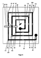
これは、少なくとも1個の交点を備えた少なくとも1個のクローズドループ(DE102013018680A1)、又は少なくとも1個のブリッジを備えた少なくとも1個のクローズドループ(DE102010022611A1)を有する回転カウンタでは異なる。これらの回転カウンタでは1個のスパイラルの両端部が互いにクローズドループに接続されている。n巻きでは直接接続は(n−1)巻きと交差する。従って2巻きスパイラルは1個の交点を備えたループとなり、3巻きスパイラルは2個の交点を備えたループとなる。各巻きは最大2個の磁壁を受容できるので、n巻きのループでは最大2n個の磁壁が存在できる。 This is different for rotation counters with at least one closed loop (DE1020130186880A1) with at least one intersection, or at least one closed loop (DE102010022611A1) with at least one bridge. In these rotation counters, both ends of one spiral are connected to each other in a closed loop. In n-winding, the direct connection intersects with (n-1) winding. Therefore, the 2-roll spiral is a loop with one intersection, and the 3-roll spiral is a loop with two intersections. Since each winding can accept up to two domains, there can be up to 2n domains in an n-winding loop.
クローズドループでは通常の計数動作時にDWは生成又は消去されない。磁壁の消去又は生成は計数エラーを招く結果となり、排除されなければならない。少なくとも1個のクローズドループを有する回転カウンタは、初期化プロセスにおいて正確な数の磁壁がセンサ要素に書き込まれることを要求する。 In the closed loop, DW is not generated or erased during normal counting operation. Elimination or formation of domain walls results in counting errors and must be eliminated. A rotation counter with at least one closed loop requires that an exact number of domain walls be written to the sensor element during the initialization process.
DWGを有するオープンスパイラルを備えた回転カウンタの幾つかの実施形態は、機械的に初期化できる。これは例えばn巻きのスパイラルにおいて、スパイラルを完全に磁壁で満たすために、センサ要素若しくはセンサシステムの外側の磁石が少なくともn回転動くことによって起こる。続いて反対方向にn回転すると、スパイラルは磁壁が空になる。回転を右から左に計数する応用に対しては、初期化のために中央位置でスパイラルは最大n回転後にDWで満たされ、それから反対の回転方向にn/2回転するとn/2DWまで空になる。 Some embodiments of a rotation counter with an open spiral having DWG can be mechanically initialized. This occurs, for example, in an n-winding spiral, where the sensor element or the magnet outside the sensor system moves at least n turns to completely fill the spiral with a domain wall. Then, when n rotations are performed in the opposite direction, the domain wall of the spiral becomes empty. For applications that count rotations from right to left, the spiral at the center position is filled with DW after a maximum of n rotations for initialization, and then n / 2 rotations in the opposite direction empty up to n / 2DW. Become.
前述した全ての回転カウンタで共通しているのは、回転の計数が、クローズドループ内で磁壁を輸送することにより、若しくはオープンスパイラル内で磁壁を輸送して生成又は消去することにより、無電流で行われる点である。計数された回転を一対一で対応するDWポジション及び/又はDW数によりセンサ要素に記憶することも無電流で行われる。 What all the rotation counters mentioned above have in common is that the rotation count is generated or eliminated by transporting the domain wall in a closed loop or by transporting the domain wall in an open spiral. It is a point to be done. It is also performed without current to store the counted rotations in the sensor element according to the corresponding DW position and / or the number of DWs on a one-to-one basis.
これに対してセンサ要素を読み出すために電力が必要とされる。このために好適な実施形態において、巨大磁気抵抗効果(GMR)又はトンネル磁気抵抗効果(TMR)が利用されて、複数のセンサ要素又は1個のセンサ要素の複数の部分が公知の先行技術によりホイートストンハーフブリッジ又はホイートストンブリッジに接続されている。 On the other hand, power is required to read out the sensor element. In a preferred embodiment for this, the giant magnetoresistive effect (GMR) or tunnel magnetoresistive effect (TMR) is utilized to allow multiple sensor elements or multiple parts of a single sensor element to be wheatstoned by known prior art. It is connected to a half bridge or a Wheatstone bridge.
磁化に応じてセンサ要素は種々の部分に異なる電気抵抗若しくは異なる電位を有し、これらはセンサ要素又はセンサ要素の一部がホイートストンハーフブリッジ又はホイートストンブリッジに接続されている場合は読出し可能である。磁化状態を呼び出すために、測定電流がセンサ要素(若しくはホイートストン(ハーフ)ブリッジ)に通されて、測定結果が所定の閾値と比較される。閾値を下回るか又は上回るかによって、測定結果が例えば「このハーフブリッジにDWが存在する」状態に相当するか否かを決定できる。 Depending on the magnetization, the sensor element has different electrical resistances or different potentials in different parts, which are readable if the sensor element or part of the sensor element is connected to a Wheatstone half bridge or Wheatstone bridge. To recall the magnetized state, the measured current is passed through a sensor element (or Wheatstone (half) bridge) and the measurement result is compared to a predetermined threshold. Whether the measurement result corresponds to, for example, "the presence of DW in this half bridge" can be determined depending on whether the measurement result is below or above the threshold value.
DE102008063226A1による回転カウンタにおいて、初めて半巻きの個別接点接触を有する菱形がホイートストンハーフブリッジに導入された。この特に有利な構成は正方形を用い、巻き当り互いに90度の角度で4個のウェブを使用する。それぞれ2個のウェブは四分円又は四分円状の多角線と互いに接続されている。四分円は電気接点で覆われており、更にこれらの電気接点は境を接するウェブの部分を、電気接点の間で全てのウェブの接触されない部分が好ましくは同じ長さになるように覆っている。各巻きの4個のウェブは、2個のホイートストンハーフブリッジに接続されている。基準方向は菱形若しくは正方形の対角で、Vcc接点とgnd接点との間の線に対して垂直に位置している。これにより各磁界角度について、1個の正方形(菱形)スパイラルのみで回転数に対する常に一対一で対応する割当てが可能である。このことは、刊行物「IEEE磁気学会議45巻10号3792−3795頁、2009年」に記載されているように、センサで計数可能な全ての回転について計数された回転による磁化の一対一で対応する割当てを許す。 In the rotation counter by DE102008063226A1, for the first time a rhombus with half-wound individual contact contacts was introduced into the Wheatstone half bridge. This particularly advantageous configuration uses squares and uses four webs at 90 degree angles to each other per winding. Each of the two webs is connected to each other with a quadrant or quadrant polygonal line. The quadrant is covered with electrical contacts, which further cover the bordering parts of the web so that all non-contact parts of the web between the electrical contacts are preferably of the same length. There is. The four webs on each roll are connected to two Wheatstone half bridges. The reference direction is a rhombus or a square diagonal and is located perpendicular to the line between the Vcc and gnd contacts. As a result, for each magnetic field angle, it is possible to always assign one-to-one correspondence to the rotation speed with only one square (diamond) spiral. This is a one-to-one magnetization of the rotations counted for every rotation countable by the sensor, as described in the publication "IEEE Electromagnetism Conference Vol. 45, No. 10, pp. 3792-3795, 2009". Allow the corresponding allocation.
このジオメトリにより、n>10の回転数を測定できる回転カウンタが可能になる。ノヴォテヒニーク社のセンサシステム「RSM2800」において、16回転までの計数のための正方形スパイラル技術的に実現されている。 This geometry enables a rotation counter that can measure the number of rotations n> 10. In Novotehinique's sensor system "RSM2800", it is technically realized as a square spiral for counting up to 16 rotations.
スパイラル又はループの内部で磁壁が最も長時間局在している幾何学的領域を、以下に磁壁位置(DW位置)と表記する。正方形又は菱形スパイラルにおいて、これはそれぞれ2個の直線ウェブを互いに接続している四分円又は四分円状の多角線である。DWが四分円を通過するには、外部磁界は90度プラス通常5度〜20度のヒステリシス角度だけ回転しなければならない。DWが四分円−ウェブ移行部に輸送されて、そこにある磁界がDWをデピニングするとすぐに、DWはウェブを数100m/secの速度で100ns以内に通過する。この非常に短い時間の内部では、磁界の回転は無視できるほど小さい。 The geometrical region where the domain wall is localized for the longest time inside the spiral or loop is hereinafter referred to as the domain wall position (DW position). In a square or diamond spiral, this is a quadrant or quadrant polygonal line connecting two straight webs to each other. In order for the DW to pass through the quadrant, the external magnetic field must rotate by a hysteresis angle of 90 degrees plus usually 5 to 20 degrees. As soon as the DW is transported to the quadrant-web transition and the magnetic field there depins the DW, the DW passes through the web at a speed of several hundred m / sec within 100 ns. Within this very short time, the rotation of the magnetic field is negligibly small.
正方形スパイラル(若しくは正方形ループ)において巻き当り4個の四分円、従って4個のDW位置があり、これらは2個のホイートストンハーフブリッジの電気接点で覆われている。1個のDW位置上にはVcc接点があり、これと相対するDW位置上にはgnd接点があり、これらの間にある2個のDW位置はそれぞれ1個の中間接点で覆われている。 In a square spiral (or square loop) there are four quadrants per winding, thus four DW positions, which are covered by the electrical contacts of two Wheatstone half bridges. There is a Vcc contact on one DW position, a gnd contact on the opposite DW position, and the two DW positions between them are each covered by one intermediate contact.
前述した全ての公知の先行技術による回転カウンタにおいて、ホイートストンハーフブリッジ中間接点と接触しているDW位置は180度の角度間隔を有している。 In all known prior art rotation counters described above, the DW positions in contact with the Wheatstone half-bridge intermediate contacts have an angular spacing of 180 degrees.
GMR層スタックにおける基準磁化の方向を選択することにより、DWがDW位置で中間接点下に配置されている場合は、ホイートストンハーフブリッジは中央電位にあり、DWがDW位置でVcc接点又はgnd接点下に配置されている場合は、ホイートストンハーフブリッジは高電位又は低電位にあるTMR層スタックに対して、これはより可変に選択できる。 By selecting the direction of reference magnetization in the GMR layer stack, if the DW is located below the intermediate contact at the DW position, the Wheatstone half bridge is at the central potential and the DW is below the Vcc or gnd contact at the DW position. When located in, the Wheatstone half bridge is more variable choice for TMR layer stacks at high or low potentials.
各180度の磁界回転に対して、センサ要素に記憶されている磁壁はエラーのない動作においては隣接のホイートストンハーフブリッジに輸送される。DW数が一定の回転カウンタではその際にDW配置はセンサ要素内で180度の角度間隔だけ移動し、1個のDWGを有するスパイラルでは更にスパイラル内の磁壁の数はDWだけ変化する。この運動の証明は、ホイートストンブリッジ若しくはホイートストンハーフブリッジの電気的読出しによって行われる。 For each 180 degree magnetic field rotation, the domain wall stored in the sensor element is transported to the adjacent Wheatstone half bridge in error-free operation. In a rotation counter having a constant DW number, the DW arrangement moves within the sensor element by an angular interval of 180 degrees, and in a spiral having one DWG, the number of domain walls in the spiral changes by DW. Proof of this movement is provided by electrical reading of the Wheatstone bridge or Wheatstone half bridge.
これら全ての回転カウンタに共通しているのは、センサシステムの磁石の磁界Hは動作時にHminとHmaxの間の「磁界窓」の内部になければならないことであり、ここでHminは最大デピニング磁界Hdepinnより大きく、Hmaxはセンサ要素の核生成磁界HNukと等しいか又は小さくなければならない。即ち
Hdepinn<Hmin≦H<Hmax<HNuk
最大磁界Hmax及び最小磁界Hminは応用によって設定される。これら全ての回転カウンタで更に共通しているのは、センサ要素は応用の最大磁界Hmaxと最小磁界Hminにおいて、例えば10−7より小さい何らかのエラー確率に関して適切にテストされていることである。この磁界窓の内部で磁壁は確実に輸送される。
What all these rotation counters have in common is that the magnetic field H of the magnets in the sensor system must be inside the "magnetic field window" between H min and H max during operation, where H min is Greater than the maximum depinning field H depinn, H max must be equal to or less than the nucleation magnetic field H Nuk of the sensor element. That is, H depinn <H min ≤ H <H max <H Nuk
The maximum magnetic field H max and the minimum magnetic field H min are set by application. Further common to all these rotation counters is that the sensor elements have been properly tested at the maximum and minimum magnetic fields H min of the application, for example with some error probability less than 10-7. The domain wall is reliably transported inside this magnetic field window.
DE102011075306A1による回転カウンタを除き、上述した全ての先行技術による回転カウンタに共通しているのは、エラー状態の認識が設けられておらず、実施形態で実現されていないことである。 Except for the rotation counter according to DE102011075306A1, what is common to all the rotation counters according to the prior art described above is that the recognition of the error state is not provided and is not realized in the embodiment.
DE102011075306A1による回転カウンタは、消去された磁壁又は核生成された磁壁によってエラー状態を認識するために、反対の回転方向を持つ2個の(菱形)スパイラルの配置を使用する。両スパイラルはそれぞれ1個の磁壁生成器(DWG)か、又は中央に1個の共通DWGを有している。そのため通常の計数動作では磁界が180度回転するごとにDWがスパイラルに注入されて、DWGから離れる方向に輸送され、並びに同時に他のスパイラルにおいてはDWGに向かって輸送されるDWがDWGによって注入されるDWとの対消滅によって消去される。機械的にブロックされた最終ポジションにおいて、一方の最終ポジションでは例えばccw回転方向を有するスパイラルは完全に磁壁で満たされ、cw回転方向を有するスパイラルはDWがなく、並びに他方の最終ポジションではccw回転方向を有するスパイラルはDWがなく、cw回転方向を有するスパイラルは完全に磁壁で満たされている。これらの回転カウンタにおいて両スパイラルにおける磁壁の総数は等しいままである。これによりスパイラルにおいて磁壁が生成または消滅したとき認識することが可能になる。なぜなら、それによって磁壁の総数が通常の計数動作で設けられているDW数に対して変化するからである。通常の計数動作ではDW数は合計のみが一定であるが、各個々のスパイラルではそうでないために、エラー状態においてどのスパイラルでエラーが発生したか検知することは可能ではない。従ってこの解決によってはエラー状態で回転数を把握することも可能ではない。 The rotation counter by DE102011075306A1 uses an arrangement of two (diamond) spirals with opposite rotation directions to recognize the error condition by the erased domain wall or the nucleated domain wall. Both spirals each have one domain wall generator (DWG) or one common DWG in the center. Therefore, in normal counting operation, every time the magnetic field rotates 180 degrees, DW is injected into the spiral and transported away from DWG, and at the same time, DW transported toward DWG in other spirals is injected by DWG. It is erased by pair annihilation with DW. In the mechanically blocked final position, for example, the spiral with the ccw rotation direction is completely filled with the domain wall in one final position, the spiral with the cw rotation direction has no DW, and the ccw rotation direction in the other final position. The spiral having the cw rotation direction has no DW, and the spiral having the cw rotation direction is completely filled with the domain wall. In these rotation counters, the total domain walls in both spirals remain equal. This makes it possible to recognize when a domain wall is created or disappears in a spiral. This is because the total number of domain walls changes with respect to the number of DWs provided in the normal counting operation. In the normal counting operation, only the total number of DWs is constant, but since it is not the case in each individual spiral, it is not possible to detect in which spiral the error occurred in the error state. Therefore, depending on this solution, it is not possible to grasp the rotation speed in an error state.
センサによる誤測定及び/又は誤機能の認識、並びに測定値の冗長的把握は、とりわけ自動車分野ではしばしば様々な規則や規格の要求および対象である(例えばASILC)。 Recognition of erroneous measurements and / or erroneous functions by sensors, and redundant grasping of measured values are often the requirements and objects of various rules and standards, especially in the automotive field (eg ASILC).
磁気回転カウンタには次のエラー状態がある。
a.ホイートストン(ハーフ)ブリッジの内部の短絡又は伝導路若しくはセンサウェブの中断に基づく電気的エラー状態
b.DW数の減少(DW対消滅)又は増加(DW核生成)又はDWセンサ要素内におけるDWの(部分的)「不動」(DWピニング)に基づく磁気的エラー状態
短絡又は伝導路中断若しくはセンサウェブ中断による電気的エラー状態は、ホイートストン(ハーフ)ブリッジの許容信号レベルである高レベル、中レベル又は低レベルに合致しない信号レベルを発生させる。電気的エラー状態は、計数された回転の検知を永続的に妨げる。
The gyromagnetic counter has the following error conditions:
a. Electrical error conditions due to short circuits inside the Wheatstone (half) bridge or interruptions in the conduction path or sensor web b. Magnetic error condition due to decrease (DW pair annihilation) or increase (DW nucleation) or (partial) "immobility" (DW pinning) of DW within the DW sensor element Short circuit or conduction path interruption or sensor web interruption The electrical error condition due to causes a signal level that does not match the acceptable signal level of the Wheatstone (half) bridge, high, medium or low. Electrical error conditions permanently interfere with the detection of counted rotations.
エラー状態「DWピニング」では、回転計数中に少なくとも1個のDWが少なくとも半回転に対して輸送されず、それによって他の通常の輸送された磁壁との角度間隔が変化する。エラー状態「DW対消滅」では、DWがピニングされたDWに輸送されて、これら2個の磁壁が解消する。エラー状態「DW核生成」では、センサ要素内で互いに180度の角度間隔を有する2個の磁壁が生成され、又は各2個の磁壁の数倍が生成される。これらの「磁気」エラー状態は、たいてい回転数の正しい検知を妨げる。即ちそれらは誤測定につながる。 In the error state "DW pinning", at least one DW is not transported for at least half a rotation during rotation counting, thereby changing the angular spacing from other normal domain walls transported. In the error state "DW pair annihilation", the DW is transported to the pinned DW, and these two domain walls are eliminated. In the error state "DW nucleation", two domain walls having an angular distance of 180 degrees from each other are generated in the sensor element, or several times each of the two domain walls is generated. These "magnetic" error conditions often prevent correct detection of revs. That is, they lead to erroneous measurements.
本発明の課題は、既に進行中の動作において外部の補助手段と比較することなく、回転数の誤測定を認識し、好適な構成において新たに初期化することなく回転カウンタの継続動作を可能にする回転カウンタを提供することである。 An object of the present invention is to recognize an erroneous measurement of the rotation speed in an operation that is already in progress without comparing it with an external auxiliary means, and to enable continuous operation of the rotation counter without newly initializing it in a suitable configuration. Is to provide a rotation counter to do.
この課題は請求項1の特徴部の特徴によって解決される。有利な構成が従属請求項に記載されている。
This problem is solved by the feature of the feature section of
本発明の本質は、まず回転要素若しくは磁極ホイール若しくはリニア磁気スケールによって生成される外部磁界の設定可能な特定すべき回転数を決定するための磁気回転カウンタが設けられていることにあり、この磁気回転カウンタは、
● オープンスパイラル又は多巻きクローズドループからなる磁壁伝導路を含み、これらの磁壁伝導路はGMR層スタック又は局所的に存在するTMR層スタックを有する軟磁性層によって形成されており、及び
● それらに180度磁壁を導入でき、設定可能なスパイラル部分又はループ部分の電気抵抗を測定することにより−一部公知の先行技術に従って探し出すことができ、
● しかしながら本発明により、磁壁伝導路には1個又は少なくとも2個の磁壁、若しくは好適な実施形態において4個の磁壁が、磁壁の発生、ピニング又は所定の消去を行うための手段によって導入されており、及び
● 磁壁伝導路上に電気接点が設けられ、その際に磁壁伝導路が、対角線状に相対してそれぞれ1個のVcc接点及びgnd接点により協同して、又は多重読出しに対しては複数のVcc接点及びgnd接点の群において覆われるようにされ、及び
● Vcc接点及びgnd接点上にある対角線を基準にして両側に、或いは本発明による好適な実施形態において専ら片側に電気接点が設けられており、
● 上記のVcc接点とgnd接点との間の実質的に中央においてそれぞれ1巻きと接触し、又は多重読出しの場合はこれらの間にある各磁壁伝導路部分の複数の巻きと接触し、
● 上記の接点は、分離した、好ましくは並行に読み出し可能な、又は多重読出しの場合は高速に相次いで、いわば同時に読み出し可能なホイートストンハーフブリッジを形成し、
● ホイートストンハーフブリッジによって把握された抵抗比は信号レベルとしてことごとくメモリに表形式で記憶され、現在の回転数を把握するために、別のメモリに記憶されている具体的な回転数に対応する表形式の目標値パターンと連続的に比較され、及び
● 目標値パターンとホイートストンハーフブリッジによって把握された抵抗比との間に一致が存在しなければ、これらは別のメモリに記憶されている、具体的な回転数及び特定のエラーに対応する、表形式のエラー目標値パターンと比較され、
● 一対一で対応する回転値若しくは移動値、又は補正不可能なエラーとして直ちに出力可能である。
The essence of the present invention is that a magnetic rotation counter is provided for determining a configurable and specific rotation speed of an external magnetic field generated by a rotating element or a magnetic pole wheel or a linear magnetic scale. The rotation counter is
● Including domain wall conduction paths consisting of open spirals or multi-winding closed loops, these domain wall conduction paths are formed by soft magnetic layers with GMR layer stacks or locally present TMR layer stacks, and ● 180 on them. By introducing a domain wall and measuring the electrical resistance of the configurable spiral or loop portion-it can be sought according to some known prior art.
● However, according to the present invention, one or at least two domain walls, or four domain walls in a preferred embodiment, are introduced into the domain wall conduction path by means for generating, pinning or erasing the domain walls. An electrical contact is provided on the domain wall conduction path, and at that time, the domain wall conduction path is diagonally opposed to each other by one Vcc contact and gnd contact, respectively, or multiple for multiple readout. Covered with a group of Vcc and gnd contacts, and ● Electrical contacts are provided on both sides relative to the diagonal on the Vcc and gnd contacts, or exclusively on one side in a preferred embodiment according to the invention. And
● In the case of multiple reading, contact with one winding each substantially at the center between the above Vcc contact and gnd contact, or in the case of multiple readout, contact with multiple windings of each domain wall conduction path portion between them.
● The above contacts form a Wheatstone half bridge that can be read separately, preferably in parallel, or at high speed in the case of multiple reads, so to speak, simultaneously.
● The resistance ratio grasped by the Wheatstone half bridge is stored in the memory in tabular form as the signal level, and in order to grasp the current rotation speed, a table corresponding to the specific rotation speed stored in another memory. If there is no match between the target value pattern of the form and the resistance ratio ascertained by the Wheatstone half bridge, then these are stored in another memory, specifically. Compared to a tabular error target value pattern that corresponds to a typical number of revolutions and a particular error,
● It can be output immediately as a one-to-one corresponding rotation value or movement value, or an uncorrectable error.
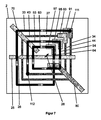
ホイートストンハーフブリッジによる回路で電位測定によってセンサ要素を読み出す代替として、本発明では、全ての巻きの(TMR)抵抗の測定によりセンサ要素を読み出す。このために各個々の巻きがそれぞれ1個のgnd接点及びそれぞれ1個のVcc接点と接触するか、又は多重読出しを用いる好適な実施形態において、1個の共通のgnd接点及び各巻き上のそれぞれ1個のVcc接点と、若しくは1個の共通のVcc接点及び各巻き上のそれぞれ1個のgnd接点と接触する。gnd接点とVcc接点は好ましくは対角線状に相対して配置されている。図15は、この回路の実施形態を示す。ここでは把握された抵抗は、ホイートストンハーフブリッジによる回路におけるように信号レベルとしてことごとくメモリに表形式で記憶され、現在の回転数を把握するために、別のメモリに記憶されている、具体的な回転数に対応する表形式の目標値パターンと連続的に比較される。 As an alternative to reading the sensor element by potential measurement in a circuit with a Wheatstone half bridge, the present invention reads the sensor element by measuring the (TMR) resistance of all windings. To this end, each individual winding contacts one gnd contact and one Vcc contact each, or in a preferred embodiment using multiple readouts, one common gnd contact and each on each winding. It contacts one Vcc contact, or one common Vcc contact and one gnd contact on each winding. The gnd contact and the Vcc contact are preferably arranged diagonally relative to each other. FIG. 15 shows an embodiment of this circuit. The resistance grasped here is stored in the memory in tabular form as a signal level as in the circuit by the Wheatstone half bridge, and is stored in another memory in order to grasp the current rotation speed. It is continuously compared with the tabular target value pattern corresponding to the rotation speed.
好適な実施形態は、公知技術に従い、回転角度センサ又は象限センサを有しており、磁界角度象限を予め選択することにより、測定値を測定された磁界角度象限と結び付いている目標値パターンとのみ比較するようにした。これにより最大限必要な比較の数は、4分の1に減少し、それにより回転数決定が加速される。
回転数を決定するために最大限必要な比較の数は更に、通常の計数動作においてDW数は一定のままであることによって少なく抑えられる。そうすることによって回転ごと及び磁界角度象限ごとに正確にそれぞれ1個の信号パターンが存在し、それによってまたそれぞれ1個の目標値パターンのみ比較のために記憶されていればよい。
A preferred embodiment has a rotation angle sensor or a quadrant sensor according to known art, and by preselecting the magnetic field angle quadrant, the measured value is only with a target value pattern associated with the measured magnetic field angle quadrant. I tried to compare. This reduces the maximum number of comparisons required by a factor of four, thereby accelerating the speed determination.
The maximum number of comparisons required to determine the number of revolutions is further reduced by keeping the DW number constant in normal counting operations. By doing so, there may be exactly one signal pattern for each rotation and each magnetic field angle quadrant, and only one target value pattern for each may be stored for comparison.
本発明により、磁壁伝導路をなすオープンスパイラル又は多巻きクローズドループは実質的に菱形に形成されており、上記の接点は菱形の角領域を覆っている。更に、2個の隣接する磁壁を使用する場合は所定の離間は、本発明により好ましくは540度に規定されている。 According to the present invention, the open spiral or the multi-winding closed loop forming the domain wall conduction path is formed substantially in a rhombus shape, and the above contact points cover the corner region of the rhombus shape. Further, when two adjacent domain walls are used, the predetermined separation is preferably defined by the present invention as 540 degrees.
GMR層スタックを使用する代りに、本発明により磁壁伝導路を軟磁性材料−例えばパーマロイ−から作製し、Vcc接点及びgnd接点を磁壁伝導路の例えば中央に設けられているTMR層スタック上に配置することも可能である。これに対して電気的中間接点は、ここでも上記の菱形の角領域で特設軟磁性磁壁伝導路と接触する。 Instead of using a GMR layer stack, the domain wall conduction path is made from a soft magnetic material-eg permalloy-according to the present invention and the Vcc and gnd contacts are placed on the domain wall conduction path, eg, the center of the TMR layer stack. It is also possible to do. On the other hand, the electrical intermediate contact also contacts the special soft magnetic domain wall conduction path in the above-mentioned rhombic corner region.
回転数を決定するための本質は、計数された回転の決定が電子評価装置によって行なわれることにあり、電子評価装置は第1ステップで全ての読み出されたホイートストンハーフブリッジ(又は抵抗測定の場合は全ての巻きの抵抗)の信号の比較を実行し、各計数可能な回転に対してホイートストンハーフブリッジ(若しくは全ての巻きの抵抗)のそれぞれの信号を保存して記憶されている表との比較を実行する。即ち、電子評価装置は、オープンスパイラル又は多巻きクローズドループの巻き1〜巻きnの測定された信号電圧から形成されるパターンが、巻き1〜巻きnについて記憶された信号パターンと一致するものを計数された回転として出力する。一致が見出されない場合、第2ステップで、全ての読み出されたホイートストンハーフブリッジ(又は抵抗測定の場合は全ての巻きの抵抗)の測定された信号と、各計数可能な回転及び各可能なエラー状態に対してホイートストンハーフブリッジ(若しくは全ての巻きの抵抗)のそれぞれの信号を保存している、別の記憶された表との比較が行なわれる。
The essence for determining the number of revolutions is that the determination of the counted revolutions is made by an electronic evaluator, which in the first step all read Wheatstone half bridges (or in the case of resistance measurements). Performs a signal comparison of all winding resistors) and compares each signal of the Wheatstone half bridge (or all winding resistors) to a stored and stored table for each countable rotation. To execute. That is, the electronic evaluation device counts patterns formed from the measured signal voltages of
正方形スパイラル又は正方形クローズドループを用いる好適な実施形態における90度の角度に基づいて、電位はそれぞれ90度の磁界回転後に変化するので、少なくとも各90度の磁界角度範囲(磁界角度象限)について対応する目標値パターンが記憶されて、角度センサ(若しくは象限センサ)の測定値を回転カウンタ信号と比較するために選択される。これに従い更に各磁界角度象限に対してエラー目標値パターンが比較のために保持される。 Based on a 90 degree angle in a preferred embodiment using a square spiral or a square closed loop, the potentials change after each 90 degree magnetic field rotation, so that at least each 90 degree magnetic field angle range (magnetic field angle quadrant) corresponds. The target value pattern is stored and selected to compare the measured value of the angle sensor (or quadrant sensor) with the rotation counter signal. Accordingly, an error target value pattern is further retained for comparison for each magnetic field angle quadrant.
ループ又はスパイラルに記録された磁化パターンは、それにより±45度の許容ヒステリシスにおいても計数された回転の一対一で対応する決定を可能にする。動作安定性の理由から、実際のヒステリシスが±30度より著しく小さい磁界強度(例えばHminの120%)が常に選択されよう。 The magnetization pattern recorded in the loop or spiral allows for a one-to-one corresponding determination of the counted rotations even with a permissible hysteresis of ± 45 degrees. For operational stability reasons, a magnetic field strength with an actual hysteresis significantly less than ± 30 degrees (eg 120% of H min ) will always be selected.
本発明による回転カウンタの全ての構成は、各計数可能な回転に対して一対一で対応する磁化パターン(MM)を有している。GMR層スタックを有する各センサ要素はホイートストン(ハーフ)ブリッジを形成し、電位測定によって読み出される。TMR層スタックを有するセンサ要素は、ホイートストン(ハーフ)ブリッジに接続できる。代替として電位測定の代わりに、TMR比が>100%と大きいためにトンネル接点抵抗の測定を行うこともできる。先行技術と異なり、本発明により電子読出し装置は常に全てのホイートストン(ハーフ)ブリッジ若しくはトンネル接点−抵抗をいわば同時に読み出す。ホイートストン(ハーフ)ブリッジの測定された信号レベルは、所定のシーケンスにおいて、例えばn巻きのスパイラルの場合は巻き1〜巻きnの順序で処理される。この信号レベルの順序を以下に信号レベルシーケンス(SPF)と表記する。測定されたSPFは、各計数可能な回転に対して電子読出し装置によって保持される記憶された目標値SPFと比較される。この目標値SPFは、先行技術に対して新規であり、電気的及び磁気的エラー状態の確実な検知を初めて可能にする。電子読出し装置は電気的エラー状態を許容されない信号レベルに基づいて検知し、磁気的エラー状態を例えば2ステップで検知する。第1ステップでは、電子読出し装置は磁気的エラー状態を、測定されたSPFと目標値SPFの間に一致が存在しないことで認識する。第2ステップでは、電子読出し装置はエラー状態を測定されたSPFと目標値エラーSPFとの一致により検知する。これらの目標値エラーSPFは、有利な構成において各想定可能な計数エラー及び各計数可能な回転について電子読出し装置内に保持されており、若しくは電子読出し装置によって算出される。目標値エラーSPFの保持又は算出先行技術に対して新規である。次に有利な構成において電子読出し装置は初期化されたMMに依存してエラー値を、又はエラー値とそれにもかかわらず正しい回転数を出力する。 All configurations of the rotation counter according to the present invention have a magnetization pattern (MM) that corresponds one-to-one with each countable rotation. Each sensor element with a GMR layer stack forms a Wheatstone (half) bridge and is read out by potential measurement. Sensor elements with a TMR layer stack can be connected to a Wheatstone (half) bridge. As an alternative, instead of measuring the potential, it is possible to measure the tunnel contact resistance because the TMR ratio is as large as> 100%. Unlike the prior art, according to the present invention, the electronic readout device always reads out all Wheatstone (half) bridge or tunnel contacts-resistors at the same time, so to speak. The measured signal levels of the Wheatstone (half) bridge are processed in a predetermined sequence, for example in the case of an n-winding spiral, in the order of winding 1-winding n. The order of these signal levels is hereinafter referred to as a signal level sequence (SPF). The measured SPF is compared to a stored target value SPF held by the electronic readout device for each countable rotation. This target value SPF is new to the prior art and allows for the first time reliable detection of electrical and magnetic error conditions. The electronic readout device detects the electrical error state based on an unacceptable signal level and detects the magnetic error state in, for example, two steps. In the first step, the electronic readout device recognizes the magnetic error condition by the absence of a match between the measured SPF and the target value SPF. In the second step, the electronic readout device detects the error state by matching the measured SPF with the target value error SPF. These target value error SPFs are held in the electronic reading device for each possible counting error and each countable rotation in an advantageous configuration, or are calculated by the electronic reading device. Target value error SPF retention or calculation is new to the prior art. In the next advantageous configuration, the electronic readout device relies on the initialized MM to output an error value, or an error value and nevertheless the correct number of revolutions.
3種類の可能な磁気エラータイプであるDWピニング、DW対消滅及びDW核生成の検知は、通常の計数動作でDW数が一定のままである場合のみ可能である。本発明による有利な構成は、初期化後にエラーのない計数動作でDW数が常に変化しないままであるセンサ要素を使用する。即ち、センサ要素はDW生成器(DWG)を有していないか、又は2個の相補的に作用するDW生成器(即ち第1のDWGでDWが生成されるのと同時に第2のDWGでDWが対消滅される)を有している。 The detection of the three possible magnetic error types DW pinning, DW pair annihilation and DW nucleation is possible only when the DW number remains constant during normal counting operations. An advantageous configuration according to the present invention uses a sensor element in which the DW number remains unchanged at all times in an error-free counting operation after initialization. That is, the sensor element does not have a DW generator (DWG), or two complementary DW generators (ie, a second DWG at the same time that a DW is generated by the first DWG). DW is annihilated).
本発明による有利な構成は、エラーのない計数動作でDW数が一定のままであるセンサ要素と、常に回転数の把握を可能にする、4個の又はそれ以上の磁壁を含む初期化されたMMを使用する。これらのMMは、計数された回転の数の読出しにおいて冗長的であり、同様に公知の先行技術に対して新規である。 An advantageous configuration according to the present invention is initialized with a sensor element in which the DW number remains constant in an error-free counting operation and four or more domain walls that allow the rotation speed to be grasped at all times. Use MM. These MMs are redundant in reading the number of rotations counted and are also novel to the known prior art.
本発明による別の有利な構成は、位相的に冗長的回転計数を可能にするセンサ要素を使用する。 Another advantageous configuration according to the invention uses sensor elements that allow topologically redundant rotation counting.
本発明による回転カウンタの核心は、装置構成要素−所定のMMを用いるセンサ要素と、メモリ内に保持された目標値SPF及び目標値エラーSPFと、測定されたSPFと目標値SPF及び目標値エラーSPFの比較とを組み合わせたことである。有利な構成において、先行技術に対して新規である目標値SPF及び目標値エラーSPFの保持と、それらの実際に把握されたSPFとの比較は、電子読出し装置内で行われる。この先行技術に対して新規の電子読出し装置を、先行技術によるセンサ要素と組み合わせると、これら自体公知である回転カウンタによっても、初めて計数動作中のエラー監視が可能になる。 The core of the rotation counter according to the present invention is a device component-a sensor element using a predetermined MM, a target value SPF and a target value error SPF held in a memory, and a measured SPF, a target value SPF, and a target value error. It is a combination with the comparison of SPF. In an advantageous configuration, the retention of target value SPFs and target value error SPFs that are novel to the prior art and their actual grasped SPFs are compared within the electronic readout device. When a new electronic readout device for this prior art is combined with a sensor element according to the prior art, error monitoring during counting operation becomes possible for the first time even by a rotation counter known per se.
本発明の有利な構成は、DW数が一定の磁化パターン(MM)を使用する。MMは、磁壁の、若しくはMM内における一連の磁壁の内部のDWギャップ(DWL)の初期化されたポジションによって定義される。MMが回転数の把握に適しているためには、磁界変化による運動で生じる全てのMMは、有意に異なる電気信号を有していなければならない。この特性を持つ単純なパターンは、センサ要素が含んでいる最初に完全に磁壁によって占められたMMから出発して、少なくとも2個の隣接する磁壁の消去によって生じる。即ち、これらの2個のDWは、互いに180度の角度間隔を有する2個のDWLによって置き換えられており、それによって2個の残っている磁壁の間に540度の角度間隔が生じ、それぞれDWLと境を接する。通常の計数動作ではこのMMはセンサ要素の内部で計数された回転と同時に輸送され、MM内における各2個の磁壁の間の角度間隔はほとんどの時間一定にとどまる。MMの輸送時のみDWのウェブ通過が、磁壁運動のヒステリシスに制約されてわずかな角度の違いで発生できる。 An advantageous configuration of the present invention uses a magnetization pattern (MM) with a constant DW number. The MM is defined by the initialized position of the DW gap (DWL) within the domain wall, or within a series of domain walls within the MM. In order for the MMs to be suitable for grasping the number of revolutions, all the MMs generated by the motion due to the change in the magnetic field must have significantly different electric signals. A simple pattern with this property occurs by erasing at least two adjacent domain walls, starting from the MM that is initially completely occupied by the domain wall contained in the sensor element. That is, these two DWs are replaced by two DWLs having an angular spacing of 180 degrees from each other, which creates an angular spacing of 540 degrees between the two remaining domain walls, each DWL. Border with. In normal counting operation, this MM is transported at the same time as the rotation counted inside the sensor element, and the angular distance between each of the two domain walls in the MM remains constant for most of the time. Only when transporting MM, DW web passage can occur with a slight angle difference, constrained by the hysteresis of the domain wall motion.
MMの初期化は、先行技術によるオープンスパイラルにおいてもクローズドループにおいても、電流により誘導されたエルステッド磁界によって行うことができる。この場合、DW消去で常に2個の隣接する磁壁が伝導路(図3aの25)の下で対消滅し、又はDW生成で常に2個のDWが伝導路(図3aの25)の下で生成し、その後直ちに互いに180度の角度間隔に離れる。 Initialization of the MM can be performed by a current-induced Oersted magnetic field, both in the prior art open spiral and in the closed loop. In this case, DW erasure always causes two adjacent domain walls to annihilate under the conduction path (25 in FIG. 3a), or DW generation always causes two DWs to disappear under the conduction path (25 in FIG. 3a). Generate and then immediately separate from each other at an angular distance of 180 degrees.
有利な構成は、全て常に所定の順序で、例えばスパイラルの最も外側の巻きから最も内側の巻きへ読み出されるホイートストンハーフブリッジを使用する。 The advantageous configuration always uses a Wheatstone half bridge that is read out in a predetermined order, eg, from the outermost winding of the spiral to the innermost winding.
有利な正方形のスパイラル又はループにおける90度の角度に基づいて、電位はそれぞれ90度の磁界回転後に変化するので、各90度の磁界角度範囲(磁界角度象限)に対して他の信号レベルシーケンス(SPF)が生じる。 Based on 90 degree angles in a favorable square spiral or loop, the potentials change after each 90 degree magnetic field rotation, so for each 90 degree magnetic field angle range (magnetic field angle quadrant) other signal level sequences ( SPF) occurs.
MMは、磁壁が局在しているDW位置を有するホイートストンハーフブリッジの信号レベルによって表される。即ち、全てのハーフブリッジの信号レベルシーケンス(SPF)の内部で、MMの信号レベルシーケンス(SPF−MM)は通常の計数動作で特定の磁界角度象限に対して十分定義され、他の磁界角度象限に対応する他の全てのSPFとは異なっている。なぜならSPFの内部におけるSPF−MMのポジションは回転数と共に変化するからである。SPF−MMのポジションに基づいて、若しくはSPF−MMの内部におけるDWのポジションに基づいて、電子読出し装置が回転数を検知する。 The MM is represented by the signal level of the Wheatstone half bridge with the DW position where the domain wall is localized. That is, within all half-bridge signal level sequences (SPFs), the MM signal level sequence (SPF-MM) is well defined for a particular magnetic field angle quadrant in normal counting operations and other magnetic field angle quadrants. It is different from all other SPFs that correspond to. This is because the position of SPF-MM inside the SPF changes with the number of revolutions. The electronic readout device detects the number of revolutions based on the position of the SPF-MM or the position of the DW inside the SPF-MM.
有利な構成は、電子評価装置が全ての読み出されたホイートストンハーフブリッジのSPFと、各計数可能な回転(各磁界角度象限に分割されている)に対してホイートストンハーフブリッジのそれぞれの目標値SPFを保存して記憶されている表との比較を実行することによって、回転数を決定する。即ち、電子評価装置は、ホイートストンハーフブリッジ1(W1)からホイートストンハーフブリッジn(Wn)までの測定されたSPFが、W1〜Wnに対する記憶された目標値SPFと一致するものを回転数として出力する。比較する前に、角度センサ測定値が評価されて、作用する磁気要素の構成に応じて、対応する磁界角度象限(図2参照)、又はアングルスケール部分若しくはリニアスケール部分を決定する。 An advantageous configuration is that the electronic evaluator has the SPF of all read Wheatstone half bridges and the respective target value SPF of the Wheatstone half bridge for each countable rotation (divided into each magnetic field angle quadrant). The number of revolutions is determined by saving and comparing with the stored table. That is, the electronic evaluation device outputs the measured SPF from the Wheatstone half bridge 1 (W1) to the Wheatstone half bridge n (Wn) as the rotation speed, which matches the stored target value SPF for W1 to Wn. .. Prior to comparison, angle sensor measurements are evaluated to determine the corresponding magnetic field angle quadrant (see FIG. 2), or angle-scale or linear-scale portion, depending on the configuration of the acting magnetic element.
電子読出し装置は、測定されたSPFと記憶された目標値との比較に基づいて、DW数が初期化されたMM内における数に対して変化したか、又はDW数が等しい場合に(少なくとも)2個の磁壁の間の角度間隔が変化したかも認識する。このエラーは即ち目標値と一致しないSPFにつながる。エラーの種類、初期化されたMM内における磁壁の数、及び(更に)エラー状態で記憶されたSPFに応じて、電子読出し装置がこのエラーケースでなおも妥当な回転数を出力できるか否かが決まる。以下にこれについて詳述する。 The electronic readout device (at least) if the DW number changes relative to the number in the initialized MM or is equal to the DW number, based on a comparison of the measured SPF with the stored target value. It also recognizes that the angular spacing between the two domains has changed. This error leads to an SPF that does not match the target value. Whether the electronic readout device can still output a reasonable number of revolutions in this error case, depending on the type of error, the number of domain walls in the initialized MM, and (further) the SPF stored in the error state. Is decided. This will be described in detail below.
以下、上述の内容と本発明を好ましい態様と図面で詳述するが、本発明はこれらに制限されない。 Hereinafter, the above contents and the present invention will be described in detail with reference to preferred embodiments and drawings, but the present invention is not limited thereto.
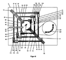
図1は、本発明による回転カウンタ1aと、回転シャフト5に取り付けたN極(N)及びS極(S)を備える磁石システム4とを有する回転カウンタシステム1を示す。回転カウンタ1aは、主要コンポーネントである回転センサUS2、360度角度センサWS3(若しくは象限センサ)及び電子装置6からなる。センサ2及び3は定置されており、回転磁界の角度位置及び回転数を検知する。電子装置6は、センサ2及び3に対する電圧供給源7、及び角度センサ3の測定値用のメモリ8と、回転センサ2の測定値用のメモリ9と、表形式で記憶された回転センサ2の目標値用のメモリ10と、記憶されたエラー状態値用のメモリ12と、処理ユニット11とによる測定値の処理を含む。この処理ユニット11は、メモリ8及び9からの測定値をメモリ10からの表の値と比較して、各測定の結果を出力する。メモリ9からの測定値とメモリ10からの目標値との比較が有効な値を出さない場合は、メモリ12からの記憶されたエラー値がメモリ9からの回転カウンタの測定値と比較されて、エラー値と並んで、発生したエラーに依存して、なおも回転数に対して妥当な値を出力する。
FIG. 1 shows a
図2は、回転カウンタシステム1による回転数の決定及びエラー検知を手順図400で模式的に示している。
● 測定サイクルの開始後に、
● 電子装置6が第1ステップで角度センサWS3及び回転数センサUS2を読み出し、
● 第2ステップでメモリ8にWS測定値W8(8a)を記憶し、メモリ9にUS測定値を表T9(9a)として記憶し、
● 第3ステップで処理ユニット11により角度センサ測定値から関連する磁界角度象限Q1、Q2、Q3又はQ4が把握され、
● 第4ステップで把握された象限(例えばQ1)に対して、目標値SPFを含むメモリ10から把握された象限に対するサブテーブル(例えばS1Q1(10a))が許容回転i(0≦i≦n)についてロードされ、
● 第5ステップで処理ユニット11により回転インデックスiは0に設定され、
● 第6ステップは回転iについて処理ユニット11による測定値9aと目標値(例えば10a)との反復比較であり、
○ それらの値が一致すれば、電子読出し装置は第7ステップで回転数iを出力して測定サイクルを終了し、又は
○ それらの値が一致しなければ、第7ステップで回転インデックスiは1だけ高められ、及び
○ 第8ステップでi>nであるかチェックされ、
■ i>nであれば、第9ステップでエラー検知が行われ、
■ そうでない場合は、第6ステップが回転i+1について繰り返され、
● エラー検知に対して処理ユニット11は第9ステップで回転インデックスiを0に設定し、
● 第10ステップで回転iについて目標値エラーSPFを含むメモリ12から予め計算されたエラーmについてのm(i)(0≦j≦m)サブテーブル(例えばSF1Q1(12a))を読み取り、
● 第11ステップで回転インデックスjは0に設定され、
● 第12ステップは、回転iについて測定値9aとエラー状態jに対する目標値エラーSPF(例えばサブテーブルSF1Q1(12a))との比較であり、
○ 値が一致すれば、電子読出し装置は第13ステップで回転数iとエラー状態に対するエラー値を出力して、測定サイクルを終了し、
○ 値が一致しなければ、第14ステップで回転インデックスjは1高められ、
○ 第15ステップでj>mであるかチェックされ、
■ j≦mであれば、予め計算されたエラーj+1について第12ステップが繰り返され、
■ j>mであれば、第16ステップで、回転インデックスi>nであるか質問され、
● そうであれば、第17ステップで1個のエラー値のみが出力されて、測定サイクルが終了し、
● そうでなければ、第17ステップで回転インデックスiは1高められて、ステップ10が繰り返され、
● 測定サイクルは回転数(ステップ7)の出力、又はエラー値を有する回転数の出力(ステップ13)、又は1個のエラー値のみの出力(ステップ17)をもって終了する。
エラー値及び有効な回転数の出力は、MMが初期化済みであり、エラー状態においてもなお有効な回転数の決定が可能であることを前提とする。
FIG. 2 schematically shows the determination of the rotation speed and the error detection by the
● After the start of the measurement cycle
● The
● In the second step, the WS measurement value W8 (8a) is stored in the
● In the third step, the
● For the quadrant (for example, Q1) grasped in the fourth step, the sub-table (for example, S1Q1 (10a)) for the quadrant grasped from the
● In the fifth step, the rotation index i is set to 0 by the
● The sixth step is a repetitive comparison between the measured
○ If those values match, the electronic readout device outputs the rotation speed i in the 7th step to end the measurement cycle, or ○ If those values do not match, the rotation index i is 1 in the 7th step. Only increased, and ○ In the 8th step, it is checked whether i> n,
■ If i> n, error detection is performed in the 9th step, and
■ If not, the sixth step is repeated for rotation i + 1 and
● For error detection, the
● In the tenth step, the m (i) (0 ≦ j ≦ m) subtable (for example, SF1Q1 (12a)) for the error m calculated in advance is read from the
● In the 11th step, the rotation index j is set to 0,
● The twelfth step is a comparison between the measured
○ If the values match, the electronic readout device outputs the rotation speed i and the error value for the error state in the 13th step, ends the measurement cycle, and ends the measurement cycle.
○ If the values do not match, the rotation index j is increased by 1 in the 14th step.
○ In the 15th step, it is checked whether j> m, and
■ If j ≦ m, the twelfth step is repeated for the pre-calculated
■ If j> m, in the 16th step, the question is asked whether the rotation index i> n.
● If so, only one error value is output in the 17th step, the measurement cycle ends, and the measurement cycle ends.
● Otherwise, the rotation index i is increased by 1 in the 17th step, and step 10 is repeated.
● The measurement cycle ends with the output of the rotation speed (step 7), the output of the rotation speed having an error value (step 13), or the output of only one error value (step 17).
The output of the error value and the effective rotation speed is based on the premise that the MM has been initialized and the effective rotation speed can be determined even in the error state.
図3は、2個のDWからなる磁化パターン(MM)で一定のDW数を可能にする3種類のセンサ要素ジオメトリを模式的に示す。 FIG. 3 schematically shows three types of sensor element geometries that enable a constant number of DWs with a magnetization pattern (MM) consisting of two DWs.
図3aは、スパイラル端に2個の尖端を有する5巻きスパイラルを模式的に示しており、垂直マークを描いた長い水平線によって表現されている。各垂直マークは正方形スパイラルにおけるDW位置(図5の四分円状の多角線302参照)を表しており、長いマークは全回転、中位の長さのマークは半回転、及び短いマークは360度の回転内部で90度若しくは270度の磁界角度増分を表している。磁壁は太い黒線によって表されている。水平線上の白い領域は、ccw方向の磁化を表し、水平線の灰色の領域はcw方向の磁化を表している。磁壁は、時間的に見ると最も長く四分円(DW位置、図6参照)内に滞在している。それゆえ磁壁は四分円内に配置され、垂直マークで表されている。例示的に2個の磁壁を含むMMは、磁壁の間に180度の角度間隔を有している。MMは、スパイラルの内部で任意の頻度で左端から記入されたポジションを経て右端に移動し、また戻ることができる。MMがセンサ要素を超え出て移動しないように、センサ要素は自体公知の図示されない機械的エンドストップを必要とする。
FIG. 3a schematically shows a 5-roll spiral having two tips at the ends of the spiral, represented by a long horizontal line with a vertical mark. Each vertical mark represents the DW position in a square spiral (see the
図3bは、スパイラル端に2個の磁壁生成器(DWG)を有する5巻きスパイラルを模式的に示しており、垂直マークと外側にDWGを表す2個の円を描いた長い水平線によって表現されている。DW位置と磁化は図3aについて記したように表されている。ここでは2個のDWギャップ(DWL)を含むMMは、それぞれ1個の十字で表されており、DWLの間に180度、及びDWLと境を接する磁壁の間に540度の角度間隔を有している。2個のDWLを含むMMは、スパイラルの内部で任意の頻度で左端から記入されたポジションを経て右端に移動し、また戻ることができる。その際にDWギャップは、図3jに示されているようにDWGと境を接することができる。MMの輸送中DW数は一定のままである。MMが右に動くと、右側のDWGで半回転ごとにDWがDWGによって生成されたDWと対消滅し、同時に左側のDWGによりDWが左からスパイラル内に注入される。MMがセンサ要素を超え出て移動しないように、センサ要素はここでも上記の機械的エンドストップを必要とする。 FIG. 3b schematically shows a 5-roll spiral with two domain wall generators (DWG) at the ends of the spiral, represented by a vertical mark and a long horizontal line with two circles representing DWG on the outside. There is. The DW position and magnetization are represented as described for FIG. 3a. Here, each MM containing two DW gaps (DWLs) is represented by a single cross, with an angular spacing of 180 degrees between the DWLs and 540 degrees between the domain walls bordering the DWLs. doing. The MM containing the two DWLs can move and return to the right end via the position entered from the left end at any frequency inside the spiral. At that time, the DW gap can border the DWG as shown in FIG. 3j. The number of DWs during transportation of MM remains constant. When the MM moves to the right, the DW on the right side annihilates with the DW generated by the DWG every half rotation, and at the same time, the DW is injected into the spiral from the left by the DWG on the left side. The sensor element again requires the mechanical end stop described above so that the MM does not move beyond the sensor element.
図3cは、5巻きクローズドループを模式的に示しており1個の円とこの円に対して垂直に立つマークによって表現され、マークは図3aにおけると同様にDW位置を表す。2個の磁壁を含むMMは、磁壁の間に180度の若しくは1620度(4.5巻き)の角度間隔を有している。MMは任意の頻度でcw又はccw方向にループを通して移動できる。このように構成されたセンサ要素は、機械的エンドストップを必要としない。 FIG. 3c schematically shows a 5-turn closed loop, which is represented by a circle and a mark standing perpendicular to this circle, and the mark represents the DW position as in FIG. 3a. The MM including the two domain walls has an angular distance of 180 degrees or 1620 degrees (4.5 turns) between the domain walls. The MM can move through the loop in the cw or ccw direction at any frequency. Sensor elements configured in this way do not require a mechanical end stop.
図3dは、図3cのセンサ要素を幾何学的に修正した簡略的な表現で示している。図3aと同様に5巻きが図示されている。下側のアーチは外側の巻きから内側の巻きへ接続するウェブを表しており、これがスパイラルを交点のあるクローズドループにしている(図7のウェブ64参照)。
FIG. 3d shows a simplified representation of the sensor elements of FIG. 3c with geometric modifications. Similar to FIG. 3a, 5 rolls are shown. The lower arch represents a web connecting from the outer winding to the inner winding, which makes the spiral a closed loop with intersections (see
図3e〜図3iは、図3aで5種類のポジションにMMを有するセンサ要素を示しており、それらのポジションは回転数0(図3e)、1(図3f)、2(図3g)、3(図3h)及び4(図3i)を表す。この割当ては応用例に依存するもので、センサ要素には依存しない。他の応用例では同じMM位置が、0〜4回転の代わりに−2〜+2回転を表すこともある。図3eのMM位置から出発すると、MMは1回転ごとにcw方向に更に4DW位置(1巻きに対応)移動する。その際に180度の角度間隔で2個の磁壁を含むMMは変化しないままである。 3e to 3i show sensor elements having MMs in five different positions in FIG. 3a, and those positions have rotation speeds of 0 (FIG. 3e), 1 (FIG. 3f), 2 (FIG. 3g), and 3 (Fig. 3h) and 4 (Fig. 3i) are shown. This allocation depends on the application example and does not depend on the sensor element. In other applications, the same MM position may represent -2 to +2 rotations instead of 0 to 4 rotations. Starting from the MM position in FIG. 3e, the MM further moves in the cw direction by the 4DW position (corresponding to one winding) for each rotation. At that time, the MM including the two domain walls at an angular interval of 180 degrees remains unchanged.
図3j〜図3lは、図3bのMMが回転数0、1及び2を表すポジションに局在するとどのように見えるかを模式的に示している。2個のDWLを含むMMはセンサ要素中を移動する際に変化しない。磁壁の総数も同様である。MMが右方向に移動すると、1回転ごとに右側で2個の磁壁が消え、左側で新しい2個の磁壁が付加される。 3j to 3l schematically show what the MM of FIG. 3b looks like when localized at positions representing rotation speeds 0, 1, and 2. The MM containing the two DWLs does not change as it moves through the sensor element. The same applies to the total number of domain walls. When the MM moves to the right, the two domain walls on the right side disappear and two new domain walls are added on the left side for each rotation.
図4は、磁化パターン(MM)を例示的に2個の尖端を有する5巻き正方形スパイラルで示している。ヒステリシスがMMの内部におけるDWポジションにどのように影響するかが示されている(図4a及び4b)。図4c及び図4dは2個のエラーのないMMを示し、図4e〜図4kは例示的なエラー状態を有するMMを示している。以下に、これらのMMがエラー状態で回転数の決定を可能にするか否か説明する。 FIG. 4 illustrates the magnetization pattern (MM) as an exemplary 5-roll square spiral with two tips. It is shown how the hysteresis affects the DW position inside the MM (FIGS. 4a and 4b). 4c and 4d show two error-free MMs, and FIGS. 4e-4k show MMs with exemplary error states. It will be described below whether or not these MMs enable the determination of the number of revolutions in an error state.
図4aは、図3aで、例えば回転ゼロを表すポジションに2個の磁壁を含むMMを示している。これら2個のDWは、互いに180度の角度間隔で2個のDW位置に配置されている。 FIG. 4a shows MM including two domain walls in a position representing, for example, zero rotation in FIG. 3a. These two DWs are arranged at two DW positions at an angular interval of 180 degrees from each other.
図4bは、図4aのMMを±45度のヒステリシスを伴って示しており、ヒステリシスは灰色の方形によって表される。±45度のヒステリシスは90度、即ち1個の象限を包含する。象限は好ましくはスパイラル(図5にそのような典型的なスパイラルを示す)に対して、ヒステリシスの「0度位置」を表す磁界角度がウェブに対して垂直になるように配置されている。このようにすることによりヒステリシス限界を表す磁界角度は、このウェブを包含する2個のDW位置を指す。象限を正方形スパイラルに対してこのように配置することにより、1巻き内部の4個の象限はそれぞれ1個のウェブを表し、ヒステリシスはこのウェブ上の各DW位置と、DWが時間的に見て最も長く滞在する隣接DW位置を表す。図4bでは図4aのDWポジションが太い垂直線で表され、関連するウェブの他方の端部におけるDW位置におけるDWポジションが細い垂直線で表されている。エラーのない通常動作でDWは2個のDW位置の間のウェブを100ns以下で通過する。ウェブの内部におけるDWポジションは、灰色の方形によって表されている。このウェブがホイートストンハーフブリッジの一部である場合、象限1及び象限2内の許容信号レベルは淡灰色の方形で表された高レベル又は中レベルであり、象限3及び象限4内の許容信号レベルは濃灰色の方形によって表された中レベル又は低レベルである(基準方向は図5〜図7に示されている通りである)。
FIG. 4b shows the MM of FIG. 4a with a hysteresis of ± 45 degrees, which is represented by a gray square. A hysteresis of ± 45 degrees includes 90 degrees, that is, one quadrant. The quadrants are preferably arranged such that the magnetic field angle representing the "0 degree position" of the hysteresis is perpendicular to the web with respect to the spiral (showing such a typical spiral in FIG. 5). The magnetic field angle that represents the hysteresis limit in this way points to the two DW positions that embrace the web. By arranging the quadrants in this way with respect to the square spiral, each of the four quadrants inside one roll represents one web, and the hysteresis is the position of each DW on this web and the DW in terms of time. Represents the adjacent DW position to stay the longest. In FIG. 4b, the DW position of FIG. 4a is represented by a thick vertical line and the DW position at the DW position at the other end of the associated web is represented by a thin vertical line. In normal operation without errors, the DW passes through the web between the two DW positions in less than 100 ns. The DW position inside the web is represented by a gray square. If this web is part of a Wheatstone half bridge, the permissible signal levels within
図4cは、例えば回転ゼロを表すポジションに4個の磁壁を含むMMを示す。電子読出し装置によって回転数ゼロが出力される。MM内の角度間隔は、左外側DWと左内側DWの間では180度、左内側DWと右内側DWの間では540度、及び右内側DWと及び右外側DWの間では180度で、外側磁壁の間は合計900度である。磁壁は、±45度の許容ヒステリシスに対応してウェブ上の全てのDWポジションを包含する方形によって表わされている。図4bと同様に、淡灰色の方形はホイートストンハーフブリッジの高レベル又は中レベルを表し、濃灰色の方形は中レベル又は低レベルを表す。 FIG. 4c shows, for example, an MM containing four domain walls in a position representing zero rotation. Zero rotation speed is output by the electronic readout device. The angular spacing in the MM is 180 degrees between the left outer DW and the left inner DW, 540 degrees between the left inner DW and the right inner DW, and 180 degrees between the right inner DW and the right outer DW. The total distance between the domain walls is 900 degrees. The domain wall is represented by a square that covers all DW positions on the web corresponding to a permissible hysteresis of ± 45 degrees. Similar to FIG. 4b, the light gray square represents the high or medium level of the Wheatstone half bridge and the dark gray square represents the medium or low level.
図4dは、図4cでcw方向に回転した後のMMを示す。全て4個の磁壁はそれぞれ4個のDW位置(四分円)だけ更に移動している。MM内の角度間隔は同じままである。このMMポジションは回転数1を表す。電子読出し装置から回転数1が出力される。磁壁は、図4cにおけるように、淡灰色及び濃灰色の方形によって表されている。
FIG. 4d shows the MM after being rotated in the cw direction in FIG. 4c. All four domain walls are further moved by four DW positions (quarter circles). The angular spacing within the MM remains the same. This MM position represents the number of
図4eは、図4cの外側磁壁も占めるポジションに900度の角度間隔で2個の磁壁を含むMMを示す。図4eで初期化されたMMが図4cのMMであった場合は、図4cのMMの測定と図4eの測定の間で2個の磁壁が対消滅した。900度の角度間隔に基づき、図4eのMMから回転数ゼロが妥当に把握できる。有利な構成において、電子読出し装置は回転数ゼロとエラー値を出力する。磁壁は、図4cにおけるように淡灰色及び濃灰色の方形によって表されている。 FIG. 4e shows an MM containing two domain walls at an angular interval of 900 degrees in a position that also occupies the outer domain wall of FIG. 4c. When the MM initialized in FIG. 4e was the MM of FIG. 4c, the two domain walls disappeared between the measurement of the MM of FIG. 4c and the measurement of FIG. 4e. Based on the angle interval of 900 degrees, the rotation speed zero can be reasonably grasped from the MM of FIG. 4e. In an advantageous configuration, the electronic readout device outputs zero speed and an error value. The domain wall is represented by light gray and dark gray squares as shown in FIG. 4c.
図4fは、180度の角度間隔で2個の磁壁を含むMMを示す。図4fで初期化されたMMが図4cのMMであった場合は、図4cのMMの測定と図4fの測定の間で2個の磁壁が対消滅した。180度の角度間隔に基づき、図4fのMMから回転数は妥当に把握されない。有利な構成において、電子読出し装置はエラー値を出力する。磁壁は、図4cにおけるように、淡灰色及び濃灰色の方形によって表されている。 FIG. 4f shows an MM containing two domain walls at an angular interval of 180 degrees. When the MM initialized in FIG. 4f was the MM of FIG. 4c, the two domain walls disappeared between the measurement of the MM of FIG. 4c and the measurement of FIG. 4f. Based on the 180 degree angle interval, the rotation speed is not properly grasped from the MM of FIG. 4f. In an advantageous configuration, the electronic readout device outputs an error value. The domain wall is represented by light gray and dark gray squares, as in FIG. 4c.
図4gは、外側DWの間に1260度、及び右外側DWと右内側DWの間に180度の角度間隔で4個の磁壁を含むMMを示す。これら2個の磁壁に基づき、回転数1が妥当に把握できる。有利な構成において、電子読出し装置は回転数1と1個のエラー値を出力する。図4cのMMに対して左外側DWは同じポジションにある。これは他の3個の磁壁のように(4DW位置)、cw方向に360度移動しておらず、cw方向回転の間ピニングされていた。磁壁は、図4cにおけるように、淡灰色及び濃灰色の方形によって表されている。
FIG. 4g shows an MM containing four domain walls at an angular interval of 1260 degrees between the outer DW and 180 degrees between the right outer DW and the right inner DW. Based on these two domain walls, the
図4hは、外側DWの間に900度、及び左内側DWと左外側DWの間に180度の角度間隔で4個の磁壁を含むMMを示す。これら2個の磁壁に基づき、回転数1が妥当に把握できる。有利な構成において、電子読出し装置は回転数1と1個のエラー値を出力する。図4cのMMと比較すると、右内側DWは同じポジションにある。これは他の3個の磁壁のように(4DW位置)、cw方向に360度移動しておらず、cw方向回転の間ピニングされていた。磁壁は、図4cにおけるように、淡灰色及び濃灰色の方形によって表されている。
FIG. 4h shows an MM containing four domain walls at an angular interval of 900 degrees between the outer DW and 180 degrees between the left inner DW and the left outer DW. Based on these two domain walls, the
図4iは、外側DWの間に900度、及び隣接する各2個の磁壁の間に180度の角度間隔で6個の磁壁を含むMMを示す。両外側磁壁に基づき、回転数ゼロが妥当に把握できる。有利な構成において、電子読出し装置は回転数ゼロと1個のエラー値を出力する。図4cのMMと比較すると、最初のMMの内部で2個の磁壁がDW核生成によって付加されている。磁壁は、図4cにおけるように、淡灰色及び濃灰色の方形によって表されている。 FIG. 4i shows an MM containing 6 domains with an angular spacing of 900 degrees between the outer DWs and 180 degrees between each of the two adjacent domains. Based on both outer domain walls, zero rotation speed can be reasonably grasped. In an advantageous configuration, the electronic readout device outputs zero rotation speed and one error value. Compared to the MM of FIG. 4c, two domains are added by DW nucleation inside the first MM. The domain wall is represented by light gray and dark gray squares, as in FIG. 4c.
図4jは、外側DWの間に1260度、及び左内側DWと左外側DWの間に180度、及び左内側DWと左中央DWの間に540度、並びに左中央DWと右中央DWの間に180度の角度間隔で6個の磁壁を含むMMを示す。図4cで4個のDWのポジションを占めるこれら4個のDWに基づき、回転数ゼロが妥当に把握できる。有利な構成において、電子読出し装置は回転数ゼロと1個のエラー値を出力する。図4cのMMと比較すると、最初のMMの外部で2個のDW磁壁がDW核生成によって付加されている。磁壁は、図4cにおけるように、淡灰色及び濃灰色の方形によって表されている。 FIG. 4j shows 1260 degrees between the outer DW, 180 degrees between the left inner DW and the left outer DW, 540 degrees between the left inner DW and the left center DW, and between the left center DW and the right center DW. Shows an MM containing 6 domain walls at 180 degree angular intervals. Based on these four DWs occupying the positions of the four DWs in FIG. 4c, the rotation speed zero can be reasonably grasped. In an advantageous configuration, the electronic readout device outputs zero rotation speed and one error value. Compared to the MM of FIG. 4c, two DW domains are added by DW nucleation outside the first MM. The domain wall is represented by light gray and dark gray squares, as in FIG. 4c.
図4kは、外側磁壁の間に1620度の角度間隔で6個の磁壁を含むMMを示す。図4aのMMと比較すると、最初のMMの外部でDW核生成によって2個の磁壁が、図4aで右外側DW、現在はMM内で右中央DWに対して540度と720度の角度間隔で付加されている。図4iのMM内の角度間隔に基づき、回転数は妥当に把握されない。有利な構成において、この場合に電子読出し装置は1個のエラー値のみを出力する。磁壁は、図4cにおけるように、淡灰色及び濃灰色の方形によって表されている FIG. 4k shows an MM containing 6 domains with 1620 degree angular spacing between the outer domains. Compared to the MM in FIG. 4a, two domain walls due to DW nucleation outside the first MM have an angular spacing of 540 degrees and 720 degrees with respect to the right outer DW in FIG. 4a and now the right center DW in the MM. It is added with. Based on the angular spacing in the MM of FIG. 4i, the number of revolutions is not reasonably grasped. In an advantageous configuration, the electronic readout device in this case outputs only one error value. The domain wall is represented by light gray and dark gray squares, as in FIG. 4c.
以下の図5〜図7は、例示的にDW数が一定のMMによる動作を可能にする実際のセンサ要素ジオメトリを平面図で示す。この例は、2個の尖端を有する180度接点接触による3巻きスパイラル(図5)、2個のDWGを有する3巻きスパイラル(図6)、及び本発明による360度接点接触による4巻き正方形ループ(図7)を模式的に示している。見やすくするために、例示的な回転センサはそれぞれの図について以下に説明する細部のみが表現されている。 The following FIGS. 5 to 7 show, for example, a plan view of the actual sensor element geometry that enables the operation by the MM having a constant DW number. Examples of this example are a 3-roll spiral with 180-degree contact contact with two tips (Fig. 5), a 3-roll spiral with 2 DWGs (Fig. 6), and a 4-roll square loop with 360-degree contact contact according to the present invention. (Fig. 7) is schematically shown. For clarity, the exemplary rotation sensor represents only the details described below for each figure.
図5は、回転センサの本発明による構成を示す。第2のセンサ要素は、この例では端部が尖った3巻き正方形スパイラル20である。尖端21は外側巻きの端部であり、尖端22は最も内側の巻きの端部である。スパイラルは、GMR効果を示す磁性層スタックからなる。基準方向28は正方形の巻きに対して対角線状である。第1の最も外側の巻きは、ウェブ3l、32、33及び34からなり、第2の中央の巻きはウェブ41、42、43及び44からなり、第3の最も内側の巻きはウェブ51、52、53及び54(時計回り)からなる。各ウェブは後続のウェブに対して90度の角度をなしている。ウェブの間の接続部は、上記のウェブ自体と同じ層スタックから作られた四分円又は四分円状の多角線302(拡大した円301内に示されている)である。この多角線は正方形スパイラルの「角」であると同時に、磁壁位置(DW位置)である。第1の最も外側の巻きはDW位置35、36、37及び38を含み、第2の巻きはDW位置45、46、47及び48を含み第3の巻きはDW位置55、56、57及び58を含む。
スパイラルは「180度接点接触方式」で電気接点を備えている。左上に1個の共通のgnd接点70、右下に1個の共通のVcc接点80、及び右上に3個の中間接点91、93及び95、左下に3個の中間接点90、92及び94、並びにセンサ要素を初期化するための狭隘部26を有する伝導路25がある。センサ要素の磁化状態は6個のホイートストンハーフブリッジを用いる電位測定によって読み出される。左下には、中間接点90、92及び94を有する3個のハーフブリッジがある。
● ホイートストンハーフブリッジW1−1は、中間接点90、gnd接点70及びVcc接点80を有するウェブ3l及び32を形成する。
● ホイートストンハーフブリッジW2−1は、中間接点92、gnd接点70及びVcc接点80を有するウェブ41及び42を形成する。
● ホイートストンハーフブリッジW3−lは、中間接点94、gnd接点70及びVcc接点80を有するウェブ51及び52を形成する。
右上には、中間接点91、93及び95を有する3個のハーフブリッジがある。
● ホイートストンハーフブリッジW1−2は、中間接点91、gnd接点70及びVcc接点80を有するウェブ33及び34を形成する。
● ホイートストンハーフブリッジW2−2は、中間接点93、gnd接点70及びVcc接点80を有するウェブ43及び44を形成する。
● ホイートストンハーフブリッジW3−2は、中間接点95、gnd接点70及びVcc接点80を有するウェブ53及び54を形成する。
FIG. 5 shows the configuration of the rotation sensor according to the present invention. The second sensor element is, in this example, a three-roll
The spiral is equipped with electrical contacts in a "180 degree contact contact system". One
The Wheatstone half bridge W1-1
The Wheatstone half bridge W2-1
The Wheatstone half bridge W3-
On the upper right are three half bridges with
The Wheatstone half bridge W1-2
The Wheatstone half bridge W2-2
The Wheatstone half bridge W3-2
センサ要素2は、ここでは最初に6個のDW(例えばセンサ要素2の核生成磁界強度を上回る磁界強度を有する磁界パルスに従う)で次のように完全に満たされている。
● 第1の最も外側の巻きにおいて、DW111はDW位置36に局在し、DW112はDW位置38に局在している。
● 第2の中央の巻きにおいて、DW113はDW位置46に局在し、DW114はDW位置48に局在している。
● 第3の最も内側の巻きにおいて、DW115はDW位置56に局在し、DW116はDW位置58に局在している。
3個のハーフブリッジはこれらのDWポジション及び基準方向28の位置により中央電位にある。ccw方向における磁化方向は濃灰色、cw方向における磁化方向は淡灰色で表現されている。更に各ウェブについて磁化方向は矢印で表示されている。GMR層スタックの基準方向28は正方形スパイラルに対して対角線状であり、左下から右上を指している。
The
● In the first outermost winding, the
● In the second central winding, the
● In the third innermost winding, the
The three half bridges are at the central potential due to their DW position and the position in the
図5に示されている6個のDWを含む磁化パターンは、回転の計数にはまだ適していない。最初になおDWが消去されなければならない。それ以外は同一の消去手順を、図6に示されているように端部に2個の磁壁生成器を有するスパイラルに基づいて説明するが、それによって直ちに本来のセンサ要素の別の実施の可能性が論じられる。 The magnetization pattern containing 6 DWs shown in FIG. 5 is not yet suitable for counting rotations. First the DW still has to be erased. The otherwise identical erasing procedure is described based on a spiral with two domain wall generators at the ends as shown in FIG. 6, which allows immediate alternative implementation of the original sensor element. Gender is discussed.
図6は、センサ要素2の変化例を示す。センサ要素2は巻き正方形スパイラル20であり、その端部に磁壁生成器23及び24が配置されているセンサ要素2は、それぞれ1個の十字で視覚化された2DWギャップ(DWL)221及び222を含む磁化パターン(MM)を有している。消去の前にDW113及びDW114(図6にはもはや示されていない。これについては図5参照)は、DWL221及びDWL222のポジションにあった。初期化は詳述しないが、例えば2段階で行われる。
1.スパイラル対角線に沿った磁界方向(例えば左下から右上)の核生成磁界強度より高い磁界強度を有する磁界パルスによるDWの核生成か、又はセンサシステムの磁界の回転、n巻きスパイラルの場合はcw方向若しくはccw方向に少なくともn+1回転(ここでは4回転)。これによりスパイラルは磁壁生成器DWG23(又はDWG24)により完全にDWで満たされる。
2.伝導路25の狭隘部26の下で十分に大きいエルステッド磁界を用いた2個のDWの対消滅、それによって2個のDWギャップDWL221及びDWL222が生じ、次にこれらが所望されたゼロ位置に移動される。
FIG. 6 shows an example of changes in the
1. 1. Nucleation of DW by a magnetic field pulse having a magnetic field strength higher than the nucleation magnetic field strength in the magnetic field direction along the spiral diagonal line (for example, lower left to upper right), or rotation of the magnetic field of the sensor system, cw direction in the case of an n-winding spiral, or At least n + 1 rotations in the ccw direction (4 rotations here). As a result, the spiral is completely filled with DW by the domain wall generator DWG23 (or DWG24).
2. Annihilation of two DWs using a sufficiently large Oersted magnetic field under the
図5に示されたセンサ要素の尖端21及び22の代わりに、図6の正方形スパイラル20は端部に2個の磁壁生成器(DWG)23及び24を備えている。回転数を決定するために、測定されたSPFにおけるDW112及び/又はDW115のポジションが把握される。2個のDWGを有するスパイラルに対する電気接触は、常に「180度接点接触」(図5参照)であり、図6では、見やすさのために省略された。GMR層スタックの基準方向28は、正方形スパイラルに対して対角線状であり、左下から右上を指している。
Instead of the
図7は、4巻きクローズドループ27からなる本発明による回転センサ2の別の構成を示す。この例では2個のDW111及びDW112を540度の角度間隔を含むMMが、狭隘部26を有する伝導路25で初期化された。GMR層スタックの基準方向28はここでも正方形スパイラルに対して対角線状であり、左下から右上を指している。このループは図5におけるスパイラルと同様に、但し1個の共通のgnd接点70、1個の共通のVcc接点80、及びVcc接点からgnd接点まで結ぶ線の右半分に局在している4個の中間接点91、93、95及び97からなる「360度接点接触」と電気的に接触する。センサ要素の磁化状態は、4個のホイートストンハーフブリッジによる電位測定によって読み出される。
● ホイートストンハーフブリッジWHB1は、中間接点91、gnd接点70及びVcc接点80を有するウェブ33及び34を形成する。
● ホイートストンハーフブリッジWHB2は、中間接点93、gnd接点70及びVcc接点80を有するウェブ43及び44を形成する。
● ホイートストンハーフブリッジWHB3は、中間接点95、gnd接点70及びVcc接点80を有するウェブ53及び54を形成する。
● ホイートストンハーフブリッジWHB4は、中間接点97、gnd接点70及びVcc接点80を有するウェブ63及び64を形成する。
4個のホイートストンハーフブリッジWHB1〜WHB4は、同時に巻きW1〜W4と相関関係にある。
FIG. 7 shows another configuration of the
The Wheatstone half-bridge WHB1 forms
The Wheatstone half-bridge WHB2 forms
The Wheatstone half-bridge WHB3 forms
The Wheatstone half-bridge WHB4 forms
The four Wheatstone half bridges WHB1 to WHB4 are simultaneously wound and correlated with W1 to W4.
図8は、本発明による回転を測定するためのセンサ要素2の別の例示的な構成を示す。この例ではセンサ要素2は2個の部分スパイラル20a及び20bからなり、それぞれ尖端21及び22と、4個の巻き及び「360度接点接触」を有しており、これは部分スパイラル20aでは接点71(gnd)、81(Vcc)、91、93、95及び97(中間接点)からなり、並びに部分スパイラル20bでは72(gnd)、82(Vcc)、99、101、103、l05及び107(中間接点)からなり、4個の磁壁DW111、DW112、DW113及びDW114は初期化された。この構成において、これら4個の磁壁は、それぞれ2個の磁壁を含む2個の論理的磁化パターンを形成する。DW111及びDW112は部分スパイラル20aのMMを形成し、並びにDW113及びDW114は第2のMMを形成する。各MMは、図示された例では「ゼロポジション」にあり、cw方向に3回転動くことができる。DW111とDW112の間、及びDW113とDW114の間の角度間隔は、それぞれ540度であり、DW112とDW113の間の角度間隔は900度である。この2個の論理的MMによりこの構成は、3回転計数できるチップ上で冗長的回転計数を有する回転カウンタとなる。初期化には狭隘部26を有する伝導路25を用いる。GMR層スタックの基準方向28は、正方形スパイラルに対して対角線状に向けられており、それぞれ左下から右上を指している。2個の部分スパイラルの測定結果は電子読出し装置(6)(図1参照)によって評価される。電子読出し装置が両部分スパイラルの測定された部分SPFから同じ回転数を把握すると、測定は2倍冗長的な結果を出す。一方のスパイラルでエラーが生じた場合は、電子読出し装置は常に回転数を、電子読出し装置が有効な状態(目標値パターンとの一致)を認識する方のスパイラルのSPFから把握できる。他方のSPFはエラー値をもたらす。この場合、適当なMM、例えば図4cのMMでエラー状態にかかわらずなおも回転数を把握できるので(エラー目標値パターンとの一致)、回転数はエラー状態にもかかわらずやはり2倍冗長的に把握される。
FIG. 8 shows another exemplary configuration of the
図9は、本発明による3回転を測定するためのセンサ要素の別の例示的な構成可能性を示す。2個の互いに入り組んで案内されたスパイラル20a(内側スパイラル)及び20b(外側スパイラル)はそれぞれ尖端21a及び22a若しくは21b及び22bと、それぞれ4個の巻き及び1個の共通の360度接点接触を有しており、これは左の部分スパイラルでは接点71(gnd)、81(Vcc)、91、93(中間接点)からなり、並びに右の部分スパイラルでは72(gnd)、82(Vcc)、95、97及び99(中間接点)からなり、これにより並行に案内された2重スパイラルによって2倍の冗長性が得られる回転カウンタを形成する。GMR層スタックの基準方向28は正方形スパイラルに対して対角線状であり、左下から右上を指している。初期化には狭隘部26を有する伝導路25を用いる。この例ではスパイラル20a内にDW111aとDW112a並びにスパイラル20b内にDW111bとDW112bの各1対のDWを、それぞれ540度の角度間隔で含むMMが初期化されている。有効な計数動作において、このセンサ要素は高レベル(100%レベル)、中レベル(50%レベル)及び低レベル(0%レベル)の信号レベルを出す。DWピニングが起きて2個のDWの間の角度間隔が変化したら、75%レベルと25%レベルの2個の新しいレベルが生じて、電子読出し装置にエラーが発生したことを示す。電子読出し装置はこのレベルを疑いなく検知できなければならない。電子読出し装置はそれにもかかわらず、75%レベル又は25%レベルを有するSPFに基づいて有効な回転数を把握できる。なぜなら一方のスパイラル(例えばスパイラル20a)内のDW対がエラーなしで輸送されたからである。即ち、SPF内には例えば高レベルの代わりに75%レベルが存在し、及び低レベルの代わりに25%レベルが存在している。保持される目標値パターン及びエラー目標値パターンは、このセンサ要素の5通りの信号レベルに適合されている。
FIG. 9 shows another exemplary configuration of a sensor element for measuring three revolutions according to the present invention. The two intricately guided
図10は、例示的な応用で40回転(U)を計数するためのセンサ要素本発明による構成を模式的に示している。センサ要素は、互いに素の最大回転数5(S5)、8(S8)及び9(S9)を有する3個のループが含んでいる。平面図ではこれらは図7に例示的に示され、ここでは簡略的に表現されているように正方形ループである。ループ、DW位置及び磁壁は図3dにおけるように記号で表されている。非冗長的回転計数のためにループS5とS8が必要とされ、これらは組み合わされて5U*8U=40Uと40回転まで計数する。冗長的回転計数のためにループS9を追加することにより、少なくとも40回転計数できるそれぞれ2個のループの3通りの組み合わせが生じる。 FIG. 10 schematically shows a configuration according to the present invention of a sensor element for counting 40 revolutions (U) in an exemplary application. The sensor elements include three loops with relatively prime maximum rotation speeds of 5 (S5), 8 (S8) and 9 (S9). In plan view, these are exemplified in FIG. 7, which are square loops, as simply represented here. Loops, DW positions and domain walls are represented by symbols as in FIG. 3d. Loops S5 and S8 are required for non-redundant rotation counting, which are combined to count up to 5U * 8U = 40U and 40 rotations. Adding the loop S9 for redundant rotation counting results in three combinations of two loops each capable of counting at least 40 rotations.
図10aは、例示的に回転数10Uに対して、ループS5(個別ループ回転数:0U)、S8(個別ループ回転数:2U)及びS9(個別ループ回転数:1U)内のMM位置を示しており、それぞれ4個のDWを左外側DWと左内側DWの間に180度、左内側DWと右内側DWの間に180度、及び右内側DWと右外側DWの間に540度の角度間隔で含む冗長的MMを有している。ここで右外側DWのポジションは、それぞれ個別ループ回転数を表す。ループの3通りの組み合わせ(S5+S8)、(S5+S9)及び(S8+S9)の各々について、電子読出し装置は個別ループ回転数からそれぞれループ組み合わせに対する回転数10Uを把握する。合計すると回転数は3倍冗長的に把握される。このために各ループ組み合わせについて、個別ループ回転数の各組み合わせに対してそれに付属するループ組み合わせの回転数が(表形式で)保存されているか、或いはこれが算出される。40回転を計数する応用において、個別ループ回転数はそれぞれ以下の通り表す。
● ループS5に対する0Uは回転数0U、5U、10U、15U、20U、25U、30U、35U及び40U(一般式n*5U)
● ループS8に対する2Uは回転数10U、18U、26U及び34U(一般式m*8U+2U)
● ループS9に対する1Uは回転数10U、19U、28U及び37U(一般式k*9U+1U)
ループが互いに素であることに基づいて、個別ループ回転数の各組み合わせについて常に必ず正確な一致が生じ、それが組み合わせの回転数である。ここでは回転数は10Uである。
目標値SPFを作成するために、正しいMMポジション若しくは基準となるDWの正しいポジションが算出されなければならない。正しいDWポジションは回転数(ここでは10U)をループの最大の回転数(ここでは5U、8U又は9U)で除した余りである。
● S5:0U(10/5=2+余り0)
● S8:2U(10/8=1+余り2)
● S9:1U(10/9=1+余り1)
FIG. 10a shows MM positions in loops S5 (individual loop rotation speed: 0U), S8 (individual loop rotation speed: 2U), and S9 (individual loop rotation speed: 1U) for an exemplary rotation speed of 10U. Each of the four DWs has an angle of 180 degrees between the left outer DW and the left inner DW, 180 degrees between the left inner DW and the right inner DW, and 540 degrees between the right inner DW and the right outer DW. It has a redundant MM that includes intervals. Here, the positions of the right outer DW represent individual loop rotation speeds. For each of the three loop combinations (S5 + S8), (S5 + S9) and (S8 + S9), the electronic readout device grasps the rotation speed 10U for each loop combination from the individual loop rotation speed. In total, the number of revolutions is grasped three times redundantly. For this purpose, for each loop combination, the rotation speed of the loop combination attached to each combination of individual loop rotation speeds is stored (in tabular form), or this is calculated. In the application of counting 40 rotations, the individual loop rotation speeds are expressed as follows.
● 0U for loop S5 is the number of
● 2U for loop S8 is rotation speed 10U, 18U, 26U and 34U (general formula m * 8U + 2U)
● 1U for loop S9 is rotation speed 10U, 19U, 28U and 37U (general formula k * 9U + 1U)
Based on the fact that the loops are relatively prime, there is always an exact match for each combination of individual loop speeds, which is the speed of the combination. Here, the rotation speed is 10U.
In order to create the target value SPF, the correct MM position or the correct position of the reference DW must be calculated. The correct DW position is the remainder of the number of revolutions (here 10U) divided by the maximum number of revolutions of the loop (here 5U, 8U or 9U).
● S5: 0U (10/5 = 2 + remainder 0)
● S8: 2U (10/8 = 1 + remainder 2)
● S9: 1U (10/9 = 1 + remainder 1)
図10bは、計数された回転数10Uに対してMMポジションを示しており、この場合はループS8において右外側DWが1回転中にピニングされており、それにより図10aと比較すると、右内側DWとの角度間隔は540度から180度に縮小し、左外側DWとの角度間隔は900度から540度に縮小した。この540度の角度間隔に基づいて、電子読出し装置は、ループS8がエラー状態(F)にあることを検知する。左外側DWと左内側DWとの180度の角度間隔は、図10aに対して変化しておらず、これに基づいて電子読出し装置はループS8に対する回転数2Uを妥当に検知する。
● S5:0U(10/5=2+余り0)
● S8:F+2U(エラー状態並びに10/8=1+余り2)
● S9:1U(10/9=1+余り1)
ループS8のエラー状態に基づいて電子読出し装置は、回転数10UをループS5及びS9の有効な値(S5:0U及びS9:1U)で把握する。4個のDWを含む冗長的MMに基づいて、電子読出し装置はループS8(F)のエラー状態にかかわらず、その個別ループ回転数2Uを把握して使用することができ、その結果としてループ(S5+S8)及び(S8+S9)の組み合わせについても、各個別ループにおける4個の磁壁を含む冗長的磁化パターンに基づいてそれぞれ回転数10Uを合計3倍冗長的に把握する。
FIG. 10b shows the MM position with respect to the counted rotation speed of 10 U. In this case, the right outer DW is pinned during one rotation in the loop S8, so that the right inner DW is compared with FIG. 10a. The angle interval with and from 540 degrees was reduced to 180 degrees, and the angle interval with the left outer DW was reduced from 900 degrees to 540 degrees. Based on this 540 degree angular interval, the electronic readout device detects that loop S8 is in an error state (F). The 180-degree angular distance between the left outer DW and the left inner DW has not changed with respect to FIG. 10a, and based on this, the electron readout device reasonably detects the
● S5: 0U (10/5 = 2 + remainder 0)
● S8: F + 2U (error state and 10/8 = 1 + remainder 2)
● S9: 1U (10/9 = 1 + remainder 1)
Based on the error state of the loop S8, the electronic reading device grasps the rotation speed 10U with the valid values (S5: 0U and S9: 1U) of the loops S5 and S9. Based on the redundant MM containing the four DWs, the electronic readout device can grasp and use its
図11は、DWGを有する5巻きスパイラルのMMを示す。これは平面図では、DWGが尖端に置き換えられた図6のスパイラルに類似の正方形スパイラルである。スパイラルはここでも簡略的に表現されている。スパイラル、DWG、DW位置、DW及びDWLは、図3bにおけるように記号で表されている。このスパイラルは基本的に先行技術から公知のセンサ要素(図11a〜図11e)であり、これはエラー状態を検出するために本発明による電子読出し装置と組み合わされる。図11f〜図11hは先行技術に対して新規である変化例を示しており、これはエラー状態、DW核生成及びDW対消滅の検知では図11a〜図11eにおける先行技術から公知のスパイラルよりも敏感である。DWGは半回転ごとにDWをスパイラルに注入するので、エラーのない動作においてDWGからスパイラルの尖端までDWチェーンをスパイラル内に配置できる。右外側DWはスパイラル内に最も大きく進入したDWであり、この構成形態では把握可能な最大回転数を表す。 FIG. 11 shows a 5-roll spiral MM with DWG. This is a square spiral similar to the spiral of FIG. 6 in which the DWG is replaced by a tip in plan view. The spiral is also simply expressed here. The spiral, DWG, DW position, DW and DWL are represented by symbols as in FIG. 3b. This spiral is basically a sensor element known from the prior art (FIGS. 11a-11e), which is combined with an electronic readout device according to the invention to detect an error condition. 11f to 11h show examples of changes that are novel to the prior art, which is more than the spiral known from the prior art in FIGS. 11a to 11e in detecting error conditions, DW nucleation and DW annihilation. Sensitive. Since the DWG injects the DW into the spiral every half revolution, the DW chain can be placed in the spiral from the DWG to the tip of the spiral in error-free operation. The right outer DW is the DW that has entered the spiral most widely, and represents the maximum number of revolutions that can be grasped in this configuration.
図11aは、6個の磁壁を含む5巻きスパイラルを示す。右外側DWは、回転数3を表す。
FIG. 11a shows a 5-roll spiral containing 6 domain walls. The right outer DW represents the number of
図11bは、4個の磁壁と、それぞれ1個の十字で表された2個のDWLを有する5巻きスパイラルを示す。2個の右外側DWLは、図11aで右外側の2個の磁壁の対消滅によって生じた。図11bのMMは回転数2を表す。DW対消滅のエラー状態は認識されない。
FIG. 11b shows a five-winding spiral with four domain walls and two DWLs, each represented by a cross. The two right outer DWLs were caused by the pair annihilation of the two right outer domain walls in FIG. 11a. The MM in FIG. 11b represents the
図11cは、4個の磁壁と、それぞれ1個の十字で表された2個のDWLを有する5巻きスパイラルを示す。DWチェーンの内部の2個のDWLは、図11aでMM内の中央の2個の磁壁の対消滅によって生じた。図11cのMMは、回転数3を表す。DW対消滅のエラー状態(F)は認識される。
FIG. 11c shows a five-winding spiral with four domain walls and two DWLs, each represented by a cross. The two DWLs inside the DW chain were caused by the pair annihilation of the two central domain walls in the MM in FIG. 11a. The MM in FIG. 11c represents the
図11dは、10個のDWを含む5巻きスパイラルを示す。図11eのMMは回転数5を表している。これは、両スパイラルが完全にDWで満たされるDW核生成後のMMとも同一である。従ってこのエラー状態(F)は認識されない。
FIG. 11d shows a 5-roll spiral containing 10 DWs. The MM in FIG. 11e represents the
図11eは、機械的エンドストップにより4回転のみ計数可能である5巻きスパイラルを示す。この第5巻き(5)は通常の計数動作から排除されており、常時この巻き内のDW核生成を検知できるようにDWは常にない。従って図11eの10個のDWを含むMMは、スパイラルが完全にDWで満たされるDW核生成によって生じている。このエラー状態(F)は、通常の計数動作−回転4まで計数−では存在しない巻き(5)における2個のDWによって認識される。
FIG. 11e shows a five-winding spiral that can count only four revolutions with a mechanical end stop. This fifth winding (5) is excluded from the normal counting operation, and there is always no DW so that DW nucleation in this winding can always be detected. Thus, the MM containing the 10 DWs of FIG. 11e is generated by DW nucleation in which the spiral is completely filled with DW. This error state (F) is recognized by the two DWs in the winding (5), which does not exist in the normal counting operation-counting up to
図11fは、図11eの5巻きスパイラルで第5巻きが幅の広いウェブを有する変化例を示す。これによりDWは最初に巻き(5)で生成する。この巻きで2個のDWのみ生成する場合、回転数はなおも妥当に把握できる。図11fのMMは、回転数2を妥当に示して巻き(5)におけるDW核生成のエラー状態を表す。
FIG. 11f shows an example of a variation in the 5-roll spiral of FIG. 11e in which the 5th roll has a wide web. As a result, the DW is first generated by winding (5). When only two DWs are generated by this winding, the rotation speed can still be grasped reasonably. The MM in FIG. 11f appropriately indicates the
図11gは、図11fの5巻きスパイラルで第1巻きが幅の狭いウェブを有する変化例を示す。これによりDWは、他の巻きにおけるより高い確率で巻き(0)でピニングされる。この巻きは機械的エンドストップによって通常の計数動作から排除されており、常に2個のDWで満たされて、巻き(0)におけるDWピニングと後続のDW対消滅の可能なエラー状態を常時検知できる。図11hのMMは、回転数1を表している。
FIG. 11g shows an example of a variation in the 5-roll spiral of FIG. 11f in which the first roll has a narrow web. This causes the DW to be pinned at winding (0) with a higher probability in other windings. This winding is excluded from normal counting operation by a mechanical end stop and is always filled with two DWs, which can always detect the possible error conditions of DW pinning at winding (0) and subsequent DW pair annihilation. .. The MM in FIG. 11h represents the
図11hは、図11gの巻き(0)で2個のDWが対消滅した後のMMを示す。このエラー状態(F)は認識される。図11gのMMは回転数1を妥当に示すと同時に、エラー状態巻き(0)におけるDW対消滅(F)を表す。
FIG. 11h shows the MM after the pair annihilation of the two DWs in the winding (0) of FIG. 11g. This error state (F) is recognized. The MM of FIG. 11g reasonably indicates the
図1では1aで示した本来の回転カウンタの本発明にとって本質的なすべてのアセンブリが枠の中に設けられているのに対し、以下の図は本発明による解決の広い用途を明らかにするものである。 In FIG. 1, all the assemblies essential to the present invention of the original rotation counter shown in 1a are provided in the frame, whereas the following figure reveals a wide range of uses of the solution according to the present invention. Is.
図12は、図1によるシャフト5上の磁石4の代わりに、磁極4a〜41を有する磁極ホイール5aと組み合わせた図1の回転カウンタ1aを示す。磁極ホイール5aが回転すると、角度センサWS3及び回転センサUS2の場所に回転磁界が形成されて、磁化パターンの磁壁をセンサ要素2内で動かす。従って各磁極ホイールポジションは角度センサ測定値と回転カウンタ測定値に対応している。回転カウンタは通過移動する磁極対の数を計数する。これは図1による磁石4の回転の計数と同様である。
FIG. 12 shows a
図13は、図1によるシャフト5上の磁石4の代わりに、磁極4a〜41を有するリニアスケール5bと組み合わせた図1の回転カウンタ1aを示す。この例では12個の磁極(6N極と交互に6S極)4a〜41を有するリニアスケール5bは、磁極がこれより多い又は少ない他のリニアスケールをも代表している。スケール5bが回転カウンタ1aに対して相対的に通過移動すると、角度センサWS3及び回転センサUS2の場所に回転磁界が形成されて、記録された磁化パターンの磁壁をセンサ要素2内で動かす。従って各リニアスケールポジションは角度センサ測定値と回転カウンタ−測定値に対応している。回転カウンタは通過移動する磁極対の数を計数する。これは図1による磁石4の回転の計数と同様である。
FIG. 13 shows a
最後に、図14a+bは、例示的に「360度接点接触」を形成するTMR接点を有するセンサ要素2の読出しを示す。この場合にスパイラル27は軟磁性材料、例えばパーマロイからなる。
Finally, FIG. 14a + b illustrates the readout of the
図14aは、例示的な4巻きクローズドループ27を平面図で示す。センサ要素2は、4個のホイートストンハーフブリッジWHB1〜WHB4による電位測定によって読み出される。
● WHB1は、gndトンネル接点71を有するウェブ33、Vccトンネル接点81を有するウェブ34、並びにウェブ33とウェブ34の間の四分円状の角及びこれらのウェブの部分を覆う中間接点91からなる。
● WHB2は、gndトンネル接点72を有するウェブ43、Vccトンネル接点82を有するウェブ44、並びにウェブ43とウェブ44の間の四分円状の角及びこれらのウェブの部分を覆う中間接点93からなる。
● WHB3は、gndトンネル接点73を有するウェブ53、Vccトンネル接点83を有するウェブ54、並びにウェブ53とウェブ54の間の四分円状の角及びこれらのウェブの部分を覆う中間接点95からなる。
● WHB4は、gndトンネル接点74を有するウェブ63、Vccトンネル接点84を有するウェブ64、並びにウェブ63とウェブ64の間の四分円状の角及びこれらのウェブの部分を覆う中間接点97からなる。
FIG. 14a shows an exemplary 4-winding
● The WHB1 consists of a
● The WHB2 consists of a
● The WHB3 consists of a
● The WHB4 consists of a
図14bは、トンネル接点を有する全てのウェブを代表して、例示的にウェブ33を図14aの横断面図で示す。ウェブ33は軟磁性材料パーマロイ501からなり、酸化物層504a及び504bによって保護されている。ウェブ中央ではgndトンネル接点71が配置されている。トンネル接点は、パーマロイ層501、トンネルバリア502(例えばAl2O3又はMgO)、基準方向(図14aの28)が書き込まれた硬磁性層スタック503、及び金電極505からなる。ウェブ33の右側には直接パーマロイ501上に金製中間接点91が載っている。トンネル接点における電流は、電極505から硬磁性層スタックとバリア502を通ってパーマロイ501に流れる。典型的なTMR接点は、TMR接点内の軟磁性層及び硬磁性層の並行磁化と逆並行磁化の間で、即ち磁壁111、112のそれぞれのポジションに依存して>100%の抵抗変化を達成する。この例では本発明による磁壁パターンの初期化、並びに現在の回転数の評価及び決定は、図5以下で既に説明されたのと同様の条件で行なわれるため、ここでは繰り返さない。
FIG. 14b illustrates the
図15は、抵抗が読み出される接点接触を変化させた図14aの回転センサを示す。gnd接点71、72、73及び74、並びにVcc接点、81、82、83及び84を有するこのループは、それぞれ1巻き上のgnd接点およびVcc接点と電気的に接触する。TMR効果が利用されるようにするために、例えばVcc接点はそれぞれ軟磁性層と接触し、gnd接点はそれぞれ硬磁性層と接触しなければならず(図14bで中間接点91が軟磁性層501と接触し、gndトンネル接点71が硬磁性層と接触するのと同様)、又はその逆でなければならない。接点は図14から逸脱してウェブ上の角に配置する代わりに、好ましくは相対するウェブ上に配置できる。例えばウェブ3l、41、51及び61上のVcc接点81、82、83及び84と、ウェブ33、43、53及び63上のgnd接点71、72、73及び74。
FIG. 15 shows the rotation sensor of FIG. 14a in which the contact contact from which the resistance is read is changed. This loop, which has
センサ要素の磁化状態は、ここでは各個々の巻きの抵抗測定によって読み出される。
外側の第1巻きW1は、gnd接点71及びVcc接点81を有するウェブ3l、32、33及び34を形成する。
第2巻きW2は、gnd接点72及びVcc接点82を有するウェブ41、42、43及び44を形成する。
第3巻きW3は、gnd接点73及びVcc接点83を有するウェブ51、52、53及び54を形成する。
最も内側の第4巻きW4は、gnd接点74及びVcc接点83を有するウェブ61、62、63及び64を形成する。
この例でも2個の隣接する磁壁DW111とDW112の間の間隔は、cw方向に見て540度である。
The magnetization state of the sensor element is read here by measuring the resistance of each individual winding.
The outer first winding W1 forms
The second winding W2 forms the
The third winding W3 forms the
The innermost fourth winding W4 forms
In this example as well, the distance between the two adjacent domain walls DW111 and DW112 is 540 degrees when viewed in the cw direction.
前述した全ての具体的な実施形態は本発明の多用途性を明らかにするものであり、本発明は冒頭に記載した種類の公知の回転センサにも、本明細書で新たに提案された回転センサにも応用できる。 All the specific embodiments described above demonstrate the versatility of the present invention, and the present invention also relates to the types of known rotation sensors described at the outset of the invention as newly proposed rotations herein. It can also be applied to sensors.
詳細な説明、実施例及び/又は以下の図面から認識される全ての特徴は、単独でも、互いに任意に組み合わせても本発明にとって本質的である。 All features recognized from the detailed description, examples and / or the drawings below are essential to the present invention, either alone or in any combination with each other.
1 回転カウンタシステム
1a 回転カウンタ
2 回転センサUS
3 角度センサWS
4 磁石システム
4a、4c、4e、4g、4i、4k N極
4b、4d、4f、4h、4j、41 S極
5 回転シャフト
5a 磁極ホイール
5b リニアスケール
6 電子装置
7 電圧供給源
8 角度センサ測定値用メモリ
8a 角度センサ測定値W8
9 回転センサ測定値用メモリ
9a 回転センサ測定値の表T9
10 回転センサの表形式で記憶された目標値のメモリ
10a−10d 第1〜第4磁界角度象限に対する目標値のサブテーブル
11 処理ユニット
12 第1〜第4磁界角度象限に対する目標値エラーSPFの目標値の表形式で記憶された目標値エラーSPF12a〜12dに対するサブテーブル
20 スパイラル
21、22 スパイラルの尖端
25 磁化パターンを初期化するための伝導路
26 伝導路25内の狭隘部
27 多巻きクローズドループ
28 基準磁化の方向
3l、32、33、34 最も外側の第1巻きのウェブ
35、36、37、38 最も外側の第1巻き内のDW位置
41、42、43、44 第2巻きのウェブ
45、46、47、48 第2巻き内のDW位置
51、52、53、54 第3巻きのウェブ
55、56、57、58 第3巻き内のDW位置
63、64 第4巻きのウェブ
65 第4巻き内のDW位置
70、71、72、73、74 gnd接点
80、81、82、83、84 Vcc接点
91、93、95、97、99 種々の巻きの中間接点
111−116 磁壁(DW)
221、222 DWギャップ
301 ウェブ51とウェブ44の角の拡大図
302 四分円状の多角線
400 手順図
501 軟磁性層
502 トンネルバリア
503 硬磁性層スタック
504a 絶縁層
504b 絶縁層
505 トンネル接点上の金電極
1
3 Angle sensor WS
4
9 Memory for
10 Memory of target value stored in tabular form of
221 222
Claims (7)
−磁壁伝導路は磁壁(DW)及び/又は磁壁ギャップ(DWL)の設定可能な一対一で対応する磁化パターン(MM)を有しており、
−前記接点は、これらによって覆われている磁壁伝導路の関連する部分と共に、並行に又は同時に読み出し可能なホイートストンブリッジ若しくはホイートストンハーフブリッジを形成し、ホイートストンブリッジ若しくはホイートストンハーフブリッジによって測定された抵抗比は信号レベルとして信号レベルシーケンス(SPF)の形で全て第1のメモリ(9)に表形式で記憶し、その信号レベルは現在の回転数若しくは移動数を把握するために、各回転数i(0≦i≦n)について第2のメモリ(10)に表形式で記憶された信号レベルシーケンスの目標値パターン(10a、10b、10c及び10d)と連続的に比較可能であり、及び
−第3のメモリ(12)が設けられており、第3のメモリには、各回転数及び各想定可能な計数エラーに対応する信号レベルシーケンスのエラー目標値パターン(12a、12b、12c、12d)が表形式で記憶されおり、第1のメモリ(9)に記憶された信号レベルシーケンスと目標値パターン(10a、10b、10c及び10d)との比較によって、目標値パターン(10a、10b、10c及び10d)と測定された前記抵抗比との間に一致が存在しなければ、第1のメモリ(9)に記憶された信号レベルシーケンスとエラー目標値パターン(12a、12b、12c、12d)との比較が行われ、発生したエラーに依存して、なおも回転数に対して妥当な値を出力することができ、
−処理ユニット(11)によって第1のメモリ(9)に記憶されている測定された信号レベルシーケンスと、第2のメモリ(10)及び第3のメモリ(12)に記憶されている信号レベルシーケンスとの連続的比較を行うことができ、及び
−回転要素(4)の全回転又は半回転、又は回転する磁極ホイール(5a)若しくは通過移動可能なリニア磁気スケール(5b)の移動ステップの間に、第3のメモリに記録された発生したエラーに対応するエラー値又は第3のメモリ(12)に記録されたエラー値及び有効な回転数を出力可能である磁気回転カウンタ。 It is a magnetic rotation counter that self-detects an error state when determining a measurable rotation number n that can be set by the rotation counter, and the rotation number n is a rotating magnetic element (4), a rotating domain wall wheel (5a), or Created by a few n magnetic poles that can be passed and moved on a pass-movable linear domain wall (5b), this magnetic domain wall has a sensor (2), in which each winding is formed in a substantially rhombic shape. Includes domain wall conduction paths consisting of open spirals (20; 20a, 20b) or multi-winding closed loops (27), these domain wall conduction paths are formed by a soft magnetic layer with a GMR layer stack or a locally present TMR layer stack. At least two domain walls (111, 112) can be introduced into them, and these domain walls are located at the corners of an open spiral (20; 20a, 20b) or a multi-winding closed loop (27). The contacts (70, 80; 91, 93, 95, 90, 92, 94 or 70) are arranged together with each other at an angle of 180 degrees and have a configurable electrical resistance of a spiral portion or a loop portion on the domain wall conduction path. , 80; 91, 93, 95, 97 or 71, 81; 91, 93, 95, 97-72, 82; 99, 101, 103, l05, 107 or 71, 81; 91, 93-72, 82; 95 , 97, 99 or 71, 81; 91~74,84; by measuring at 95), in which it is possible to locate the position of the magnetic wall,
-The domain wall conduction path has a configurable one-to-one correspondence pattern (MM) of domain wall (DW) and / or domain wall gap (DWL).
-The contacts form a Wheatstone bridge or Wheatstone half bridge that can be read in parallel or simultaneously with the relevant parts of the magnetic wall conduction path covered by them, and the resistance ratio measured by the Wheatstone bridge or Wheatstone half bridge is All signal levels are stored in the first memory (9) in tabular form in the form of a signal level sequence (SPF), and the signal level is each rotation number i (0) in order to grasp the current rotation number or movement number. ≦ i ≦ n) can be continuously compared with the target value patterns (10a, 10b, 10c and 10d) of the signal level sequence stored in the second memory (10) in tabular form, and −3. A memory (12) is provided, and in the third memory, error target value patterns (12a, 12b, 12c, 12d) of a signal level sequence corresponding to each rotation speed and each conceivable counting error are tabulated. By comparing the signal level sequence stored in the first memory (9) with the target value patterns (10a, 10b, 10c and 10d), the target value patterns (10a, 10b, 10c and 10d) and the target value patterns (10a, 10b, 10c and 10d) are obtained. If there is no match with the measured resistance ratio, a comparison is made between the signal level sequence stored in the first memory (9) and the error target value patterns (12a, 12b, 12c, 12d). We can still output a reasonable value for the number of revolutions, depending on the error that occurred.
-The measured signal level sequence stored in the first memory (9) by the processing unit (11) and the signal level sequence stored in the second memory (10) and the third memory (12). During the moving steps of the rotating magnetic pole wheel (5a) or the passable linear magnetic scale (5b), which can be continuously compared with and-full or half-turn of the rotating element (4). , A magnetic rotation counter capable of outputting an error value corresponding to an error recorded in a third memory or an error value recorded in a third memory (12) and a valid rotation speed.
Applications Claiming Priority (3)
| Application Number | Priority Date | Filing Date | Title |
|---|---|---|---|
| DE102015016164.4 | 2015-12-11 | ||
| DE102015016164 | 2015-12-11 | ||
| PCT/DE2016/000433 WO2017097284A1 (en) | 2015-12-11 | 2016-12-07 | Magnetic revolution counter for self-detecting error states when determining numbers of revolutions which can be determined by said revolution counter |
Publications (2)
| Publication Number | Publication Date |
|---|---|
| JP2019500627A JP2019500627A (en) | 2019-01-10 |
| JP6855498B2 true JP6855498B2 (en) | 2021-04-07 |
Family
ID=57850822
Family Applications (1)
| Application Number | Title | Priority Date | Filing Date |
|---|---|---|---|
| JP2018548267A Active JP6855498B2 (en) | 2015-12-11 | 2016-12-07 | Magnetic rotation counter that self-detects the error state when determining the rotation speed that can be grasped by the rotation counter |
Country Status (9)
| Country | Link |
|---|---|
| US (1) | US10859404B2 (en) |
| EP (1) | EP3387387B1 (en) |
| JP (1) | JP6855498B2 (en) |
| CN (1) | CN108369108B (en) |
| DE (1) | DE112016005624A5 (en) |
| ES (1) | ES2763529T3 (en) |
| PL (1) | PL3387387T3 (en) |
| PT (1) | PT3387387T (en) |
| WO (1) | WO2017097284A1 (en) |
Families Citing this family (19)
| Publication number | Priority date | Publication date | Assignee | Title |
|---|---|---|---|---|
| JP6855499B2 (en) * | 2015-12-11 | 2021-04-07 | ライプニッツ−インスティテュート フュア フォトニサ テヒノロギエン イー.ファウ. | Magnetic rotation counter and method for determining the rotation speed that can be grasped by the rotation counter |
| EP3387387B1 (en) * | 2015-12-11 | 2019-10-23 | Leibniz-Institut für Photonische Technologien e.V. | Magnetic revolution counter for self-detecting error states when determining numbers of revolutions which can be determined by said revolution counter |
| US10782153B2 (en) | 2016-03-08 | 2020-09-22 | Analog Devices Global | Multiturn sensor arrangement and readout |
| DE102016111995B4 (en) | 2016-06-30 | 2022-01-20 | Infineon Technologies Ag | MAGNETIC SENSOR ELEMENT |
| US11248971B2 (en) * | 2018-02-02 | 2022-02-15 | Analog Devices International Unlimited Company | Magnetic field torque and/or angle sensor |
| US20190383645A1 (en) * | 2018-06-13 | 2019-12-19 | Analog Devices Global Unlimited Company | Initialization state determination of a magnetic multi-turn sensor |
| US11460521B2 (en) * | 2019-03-18 | 2022-10-04 | Analog Devices International Unlimited Company | Multiturn sensor arrangement |
| US11448528B2 (en) * | 2019-08-02 | 2022-09-20 | Analog Devices International Unlimited Company | Resettable closed-loop multi-turn magnetic sensor |
| DE102019218351A1 (en) | 2019-11-27 | 2021-05-27 | Dr. Johannes Heidenhain Gesellschaft Mit Beschränkter Haftung | Sensor element for storing rotation or position information |
| US11519751B2 (en) | 2020-05-29 | 2022-12-06 | Analog Devices International Unlimited Company | Method of monitoring a magnetic sensor |
| US11608109B2 (en) | 2020-08-12 | 2023-03-21 | Analog Devices International Unlimited Company | Systems and methods for detecting magnetic turn counter errors with redundancy |
| US11493362B2 (en) | 2020-08-12 | 2022-11-08 | Analog Devices International Unlimited Company | Systems and methods for detecting magnetic turn counter errors |
| US11953567B2 (en) * | 2020-09-08 | 2024-04-09 | Analog Devices International Unlimited Company | Magnetic multi-turn sensor and method of manufacture |
| US11637482B2 (en) | 2020-10-08 | 2023-04-25 | Analog Devices International Unlimited Company | Magnetic sensor system for motor control |
| DE102020006987B3 (en) | 2020-11-09 | 2021-10-14 | Leibniz-Institut für Photonische Technologien e.V. (Engl.Leibniz Institute of Photonic Technology) | Magnetic system for counting revolutions with increased immunity to magnetic interference |
| DE102020132914A1 (en) | 2020-12-10 | 2022-06-15 | Analog Devices International Unlimited Company | initialization device |
| US11460323B2 (en) | 2021-02-05 | 2022-10-04 | Analog Devices International Unlimited Company | Magnetic field sensor package |
| US20220307865A1 (en) * | 2021-03-24 | 2022-09-29 | Analog Devices International Unlimited Company | Magnetic sensor system |
| US11754646B2 (en) | 2021-03-24 | 2023-09-12 | Analog Devices International Unlimited Company | Magnetic sensor system |
Family Cites Families (20)
| Publication number | Priority date | Publication date | Assignee | Title |
|---|---|---|---|---|
| DE10162752A1 (en) * | 2001-12-20 | 2003-07-03 | Philips Intellectual Property | Magnetoresistive sensor |
| DE10239904A1 (en) * | 2002-08-30 | 2004-03-04 | Horst Siedle Gmbh & Co. Kg. | Sensor element for a revolution counter |
| DE102004020149A1 (en) * | 2004-04-24 | 2005-11-24 | Horst Siedle Gmbh & Co. Kg. | Sensor element for a revolution counter |
| WO2009027046A1 (en) * | 2007-08-27 | 2009-03-05 | Institut Für Photonische Technologien E.V. | Magnetic revolution counter |
| DE102008063226A1 (en) | 2008-12-23 | 2010-07-01 | Institut Für Photonische Technologien E.V. | Magnetic revolution counter for unambiguous determining revolutions of rotating element, has resistance unit providing measurement for magnetic domain corresponding to loop segments and definite condition of revolution of rotating element |
| DE102010010893B4 (en) | 2009-03-10 | 2013-04-11 | Horst Siedle Gmbh & Co. Kg | Electrical circuit, in particular for a revolution counter |
| DE102010022611B4 (en) | 2010-06-01 | 2015-02-19 | Leibniz-Institut für Photonische Technologien e. V. | Magnetic revolution counter |
| DE102011075305A1 (en) * | 2011-05-05 | 2012-11-08 | Bayerische Motoren Werke Aktiengesellschaft | Method for the computer-aided processing of electronically stored calendar data |
| DE102011075306A1 (en) | 2011-05-05 | 2012-11-08 | Horst Siedle Gmbh & Co. Kg | Sensor element for revolution counter, comprises two helical strips having opposing winding directions, which are connected to respective wall generators that are arranged adjacent to each other |
| DE102013018680B4 (en) * | 2013-11-04 | 2022-05-25 | Leibniz-Institut für Photonische Technologien e. V. | Magnetic sensor for absolute counting of revolutions or linear distances |
| JP6048432B2 (en) | 2014-03-14 | 2016-12-21 | トヨタ自動車株式会社 | Motor control device |
| US9958511B2 (en) * | 2014-12-08 | 2018-05-01 | Infineon Technologies Ag | Soft switching of magnetization in a magnetoresistive sensor |
| DE102015210586A1 (en) * | 2015-06-10 | 2016-12-15 | Schaeffler Technologies AG & Co. KG | Method for operating a revolution sensor and corresponding revolution sensor |
| EP3387387B1 (en) * | 2015-12-11 | 2019-10-23 | Leibniz-Institut für Photonische Technologien e.V. | Magnetic revolution counter for self-detecting error states when determining numbers of revolutions which can be determined by said revolution counter |
| JP6855499B2 (en) * | 2015-12-11 | 2021-04-07 | ライプニッツ−インスティテュート フュア フォトニサ テヒノロギエン イー.ファウ. | Magnetic rotation counter and method for determining the rotation speed that can be grasped by the rotation counter |
| US10782153B2 (en) * | 2016-03-08 | 2020-09-22 | Analog Devices Global | Multiturn sensor arrangement and readout |
| US10724844B2 (en) * | 2017-12-22 | 2020-07-28 | Infineon Technologies Ag | Multi-turn counter sensor |
| US10670386B2 (en) * | 2018-04-19 | 2020-06-02 | Infineon Technologies Ag | Multi-turn counter sensor failure detection |
| US20190383645A1 (en) * | 2018-06-13 | 2019-12-19 | Analog Devices Global Unlimited Company | Initialization state determination of a magnetic multi-turn sensor |
| US11614341B2 (en) * | 2018-06-14 | 2023-03-28 | Analog Devices International Unlimited Company | Methods and devices for using multi-turn magnetic sensors with extended magnetic windows |
-
2016
- 2016-12-07 EP EP16828919.7A patent/EP3387387B1/en active Active
- 2016-12-07 DE DE112016005624.9T patent/DE112016005624A5/en not_active Withdrawn
- 2016-12-07 CN CN201680072575.1A patent/CN108369108B/en active Active
- 2016-12-07 WO PCT/DE2016/000433 patent/WO2017097284A1/en active Application Filing
- 2016-12-07 PT PT168289197T patent/PT3387387T/en unknown
- 2016-12-07 ES ES16828919T patent/ES2763529T3/en active Active
- 2016-12-07 PL PL16828919T patent/PL3387387T3/en unknown
- 2016-12-07 JP JP2018548267A patent/JP6855498B2/en active Active
- 2016-12-07 US US16/060,485 patent/US10859404B2/en active Active
Also Published As
| Publication number | Publication date |
|---|---|
| US10859404B2 (en) | 2020-12-08 |
| WO2017097284A1 (en) | 2017-06-15 |
| CN108369108A (en) | 2018-08-03 |
| PT3387387T (en) | 2019-12-30 |
| JP2019500627A (en) | 2019-01-10 |
| US20180356252A1 (en) | 2018-12-13 |
| ES2763529T3 (en) | 2020-05-29 |
| CN108369108B (en) | 2021-03-16 |
| EP3387387B1 (en) | 2019-10-23 |
| EP3387387A1 (en) | 2018-10-17 |
| PL3387387T3 (en) | 2020-07-13 |
| DE112016005624A5 (en) | 2018-11-08 |
Similar Documents
| Publication | Publication Date | Title |
|---|---|---|
| JP6855498B2 (en) | Magnetic rotation counter that self-detects the error state when determining the rotation speed that can be grasped by the rotation counter | |
| JP6855499B2 (en) | Magnetic rotation counter and method for determining the rotation speed that can be grasped by the rotation counter | |
| US11280639B2 (en) | Multiturn sensor arrangement and readout | |
| CN105723188B (en) | For rotation or the Magnetic Sensor of the absolute counting of linear range | |
| US7239131B2 (en) | Sensor element for revolution counter | |
| US20100301842A1 (en) | Magnetic revolution counter | |
| CN107735649B (en) | Method for operating a rotation sensor and corresponding rotation sensor | |
| US20170045380A1 (en) | Rotary sensing device | |
| EP3771916B1 (en) | Resettable closed-loop multi-turn magnetic sensor | |
| CN103518120A (en) | Encoder | |
| JP6791183B2 (en) | Magnetoresistive element, its manufacturing method, and position detector | |
| US11162772B2 (en) | Magnetic sensor device | |
| WO2019131393A1 (en) | Position sensing element and position sensor using same | |
| US7286392B2 (en) | Data retention indicator for magnetic memories | |
| JP2008305827A (en) | Magnetic memory and writing method for magnetic memory | |
| US20240004001A1 (en) | An initialisation device | |
| US11796301B2 (en) | Sensor element for storing rotation or position information | |
| WO2010128615A1 (en) | Storage element and storage method | |
| JP2016200522A (en) | Current detection device and magnetic field detection device using the same | |
| KR20070017043A (en) | Method for switching magnetic moment in magnetoresistive random access memory with low current |
Legal Events
| Date | Code | Title | Description |
|---|---|---|---|
| A621 | Written request for application examination |
Free format text: JAPANESE INTERMEDIATE CODE: A621 Effective date: 20180606 |
|
| A131 | Notification of reasons for refusal |
Free format text: JAPANESE INTERMEDIATE CODE: A131 Effective date: 20190625 |
|
| A601 | Written request for extension of time |
Free format text: JAPANESE INTERMEDIATE CODE: A601 Effective date: 20190925 |
|
| A521 | Request for written amendment filed |
Free format text: JAPANESE INTERMEDIATE CODE: A523 Effective date: 20191125 |
|
| A131 | Notification of reasons for refusal |
Free format text: JAPANESE INTERMEDIATE CODE: A131 Effective date: 20200407 |
|
| A601 | Written request for extension of time |
Free format text: JAPANESE INTERMEDIATE CODE: A601 Effective date: 20200623 |
|
| A601 | Written request for extension of time |
Free format text: JAPANESE INTERMEDIATE CODE: A601 Effective date: 20200904 |
|
| A521 | Request for written amendment filed |
Free format text: JAPANESE INTERMEDIATE CODE: A523 Effective date: 20201001 |
|
| A521 | Request for written amendment filed |
Free format text: JAPANESE INTERMEDIATE CODE: A821 Effective date: 20201002 |
|
| TRDD | Decision of grant or rejection written | ||
| A01 | Written decision to grant a patent or to grant a registration (utility model) |
Free format text: JAPANESE INTERMEDIATE CODE: A01 Effective date: 20210316 |
|
| A61 | First payment of annual fees (during grant procedure) |
Free format text: JAPANESE INTERMEDIATE CODE: A61 Effective date: 20210317 |
|
| R150 | Certificate of patent or registration of utility model |
Ref document number: 6855498 Country of ref document: JP Free format text: JAPANESE INTERMEDIATE CODE: R150 |
|
| R250 | Receipt of annual fees |
Free format text: JAPANESE INTERMEDIATE CODE: R250 |