JP6855231B2 - Non-planar heating chamber separation mechanism for implantable vascular occlusion delivery system - Google Patents
Non-planar heating chamber separation mechanism for implantable vascular occlusion delivery system Download PDFInfo
- Publication number
- JP6855231B2 JP6855231B2 JP2016243256A JP2016243256A JP6855231B2 JP 6855231 B2 JP6855231 B2 JP 6855231B2 JP 2016243256 A JP2016243256 A JP 2016243256A JP 2016243256 A JP2016243256 A JP 2016243256A JP 6855231 B2 JP6855231 B2 JP 6855231B2
- Authority
- JP
- Japan
- Prior art keywords
- heating chamber
- planar heating
- distal end
- delivery system
- heating element
- Prior art date
- Legal status (The legal status is an assumption and is not a legal conclusion. Google has not performed a legal analysis and makes no representation as to the accuracy of the status listed.)
- Active
Links
Images


Classifications
-
- A—HUMAN NECESSITIES
- A61—MEDICAL OR VETERINARY SCIENCE; HYGIENE
- A61F—FILTERS IMPLANTABLE INTO BLOOD VESSELS; PROSTHESES; DEVICES PROVIDING PATENCY TO, OR PREVENTING COLLAPSING OF, TUBULAR STRUCTURES OF THE BODY, e.g. STENTS; ORTHOPAEDIC, NURSING OR CONTRACEPTIVE DEVICES; FOMENTATION; TREATMENT OR PROTECTION OF EYES OR EARS; BANDAGES, DRESSINGS OR ABSORBENT PADS; FIRST-AID KITS
- A61F2/00—Filters implantable into blood vessels; Prostheses, i.e. artificial substitutes or replacements for parts of the body; Appliances for connecting them with the body; Devices providing patency to, or preventing collapsing of, tubular structures of the body, e.g. stents
- A61F2/01—Filters implantable into blood vessels
-
- A—HUMAN NECESSITIES
- A61—MEDICAL OR VETERINARY SCIENCE; HYGIENE
- A61B—DIAGNOSIS; SURGERY; IDENTIFICATION
- A61B17/00—Surgical instruments, devices or methods, e.g. tourniquets
- A61B17/12—Surgical instruments, devices or methods, e.g. tourniquets for ligaturing or otherwise compressing tubular parts of the body, e.g. blood vessels, umbilical cord
- A61B17/12022—Occluding by internal devices, e.g. balloons or releasable wires
- A61B17/12099—Occluding by internal devices, e.g. balloons or releasable wires characterised by the location of the occluder
- A61B17/12109—Occluding by internal devices, e.g. balloons or releasable wires characterised by the location of the occluder in a blood vessel
-
- A—HUMAN NECESSITIES
- A61—MEDICAL OR VETERINARY SCIENCE; HYGIENE
- A61B—DIAGNOSIS; SURGERY; IDENTIFICATION
- A61B17/00—Surgical instruments, devices or methods, e.g. tourniquets
- A61B17/12—Surgical instruments, devices or methods, e.g. tourniquets for ligaturing or otherwise compressing tubular parts of the body, e.g. blood vessels, umbilical cord
- A61B17/12022—Occluding by internal devices, e.g. balloons or releasable wires
- A61B17/12131—Occluding by internal devices, e.g. balloons or releasable wires characterised by the type of occluding device
- A61B17/1214—Coils or wires
-
- A—HUMAN NECESSITIES
- A61—MEDICAL OR VETERINARY SCIENCE; HYGIENE
- A61M—DEVICES FOR INTRODUCING MEDIA INTO, OR ONTO, THE BODY; DEVICES FOR TRANSDUCING BODY MEDIA OR FOR TAKING MEDIA FROM THE BODY; DEVICES FOR PRODUCING OR ENDING SLEEP OR STUPOR
- A61M25/00—Catheters; Hollow probes
- A61M25/01—Introducing, guiding, advancing, emplacing or holding catheters
-
- A—HUMAN NECESSITIES
- A61—MEDICAL OR VETERINARY SCIENCE; HYGIENE
- A61B—DIAGNOSIS; SURGERY; IDENTIFICATION
- A61B17/00—Surgical instruments, devices or methods, e.g. tourniquets
- A61B2017/00367—Details of actuation of instruments, e.g. relations between pushing buttons, or the like, and activation of the tool, working tip, or the like
- A61B2017/00411—Details of actuation of instruments, e.g. relations between pushing buttons, or the like, and activation of the tool, working tip, or the like actuated by application of energy from an energy source outside the body
-
- A—HUMAN NECESSITIES
- A61—MEDICAL OR VETERINARY SCIENCE; HYGIENE
- A61B—DIAGNOSIS; SURGERY; IDENTIFICATION
- A61B17/00—Surgical instruments, devices or methods, e.g. tourniquets
- A61B2017/00526—Methods of manufacturing
-
- A—HUMAN NECESSITIES
- A61—MEDICAL OR VETERINARY SCIENCE; HYGIENE
- A61B—DIAGNOSIS; SURGERY; IDENTIFICATION
- A61B17/00—Surgical instruments, devices or methods, e.g. tourniquets
- A61B2017/00743—Type of operation; Specification of treatment sites
- A61B2017/00778—Operations on blood vessels
-
- A—HUMAN NECESSITIES
- A61—MEDICAL OR VETERINARY SCIENCE; HYGIENE
- A61B—DIAGNOSIS; SURGERY; IDENTIFICATION
- A61B17/00—Surgical instruments, devices or methods, e.g. tourniquets
- A61B17/12—Surgical instruments, devices or methods, e.g. tourniquets for ligaturing or otherwise compressing tubular parts of the body, e.g. blood vessels, umbilical cord
- A61B17/12022—Occluding by internal devices, e.g. balloons or releasable wires
- A61B2017/1205—Introduction devices
- A61B2017/12054—Details concerning the detachment of the occluding device from the introduction device
- A61B2017/12068—Details concerning the detachment of the occluding device from the introduction device detachable by heat
-
- A—HUMAN NECESSITIES
- A61—MEDICAL OR VETERINARY SCIENCE; HYGIENE
- A61B—DIAGNOSIS; SURGERY; IDENTIFICATION
- A61B18/00—Surgical instruments, devices or methods for transferring non-mechanical forms of energy to or from the body
- A61B2018/00053—Mechanical features of the instrument of device
- A61B2018/00059—Material properties
- A61B2018/00071—Electrical conductivity
-
- A—HUMAN NECESSITIES
- A61—MEDICAL OR VETERINARY SCIENCE; HYGIENE
- A61B—DIAGNOSIS; SURGERY; IDENTIFICATION
- A61B18/00—Surgical instruments, devices or methods for transferring non-mechanical forms of energy to or from the body
- A61B2018/00053—Mechanical features of the instrument of device
- A61B2018/00059—Material properties
- A61B2018/00089—Thermal conductivity
Description
本発明は、移植可能な血管閉塞装置のための送達システムを目的とする。特に、本発明は、送達システムを血管閉塞装置に固定する分離ファイバを解放するために熱エネルギーを使用する、非平面加熱チャンバー分離機構に関する。 The present invention is directed to a delivery system for implantable vascular occlusion devices. In particular, the present invention relates to a non-planar heating chamber separation mechanism that uses thermal energy to release the separation fibers that secure the delivery system to the vascular occlusion device.
塞栓形成は、閉塞装置(例えば塞栓コイル)を血管の中に意図的に導入することによって血管を選択的に閉塞する(例えば故意に遮断する)非外科的な低侵襲手順である。閉塞動脈及び動脈瘤のような血管内疾患を治療するために、人体の血管構造の中に閉塞装置、例えば拡張バルーン、ステント及び塞栓コイルを位置決めして配備するためのカテーテル送達システムを使用することが現在では珍しくない。閉塞装置は、特に、従来の手術手順が不可能である場合、又は患者に大きな危険をもたらす領域を治療する場合、例えば脳内血管の中の動脈瘤を治療する場合に有効である。脳内血管を囲む繊細な組織、特に、例えば脳組織のために、脳内血管の欠陥を治療する外科手順を実行することは、非常に難しく、しばしば危険である。 Embolic formation is a non-surgical, minimally invasive procedure that selectively occludes (eg, deliberately blocks) a vessel by deliberately introducing an occlusive device (eg, an embolic coil) into the vessel. To use a catheter delivery system for positioning and deploying occlusion devices, such as dilation balloons, stents and embolic coils, within the vascular structure of the human body to treat intravascular diseases such as occluded arteries and aneurysms. Is not uncommon nowadays. The occlusive device is particularly effective when conventional surgical procedures are not possible or when treating areas that pose a great risk to the patient, such as when treating an aneurysm in an intracerebral blood vessel. Performing surgical procedures to treat intracerebral vascular defects is very difficult and often dangerous for the delicate tissues that surround the intracerebral vessels, especially for example brain tissue.
一般的に、これらの手順は、送達カテーテルの遠位端部を患者の血管構造の中に挿入することと、それを血管構造を通して所定の送達部位まで導くことと、を含む。塞栓コイルのような血管閉塞装置は送達部材の端部に取り付けられ、それが閉塞装置をカテーテルを通して押し、所望の送達部位においてカテーテルの遠位端部から外に押し出す。これらの手順と関連してきた問題のうちのいくつかは、閉塞装置配置の精度に関する。例えば、閉塞装置を送達カテーテルから放出するために使用する力によって、閉塞装置が所定の部位に過剰に突き出たり、又は前に配備された閉塞装置を押しのけることがある。また、一旦閉塞装置がカテーテルの遠位端部から外に押し出されると、閉塞装置を後退させることがでず、望まない場所まで移動することがある。多くの場合、閉塞装置を回収して別の場所に移すことは、別個の手順を必要とし、患者を更なる危険に晒す可能性を有する。 In general, these procedures include inserting the distal end of a delivery catheter into the patient's vascular structure and guiding it through the vascular structure to a given delivery site. A vascular occlusion device, such as an embolic coil, is attached to the end of the delivery member, which pushes the occlusion device through the catheter and pushes it out of the distal end of the catheter at the desired delivery site. Some of the issues that have been associated with these procedures relate to the accuracy of blocker placement. For example, the force used to release the occlusion device from the delivery catheter can cause the occlusion device to overhang at a given site or push away a previously deployed occlusion device. Also, once the occluder is pushed out of the distal end of the catheter, the occluder cannot be retracted and may move to an undesired location. In many cases, retrieving the occlusive device and moving it to another location requires a separate procedure and may put the patient at additional risk.
一旦患者の血管構造を通して標的処置部位まで適切に進行させられると、塞栓コイルは、その送達システムから分離される。従来の分離形式が、閉塞装置をその送達システムから切断するために使用されてきた。分離についてのいくつかの公知の方法は、電熱、機械的干渉又は油圧及び電解質分離を含む。これらの従来の分離機構のそれぞれは、1つ又は2つ以上の不利点、例えば大きい固い領域、閉塞装置のその送達システムからの一貫性のない分離、及び/又は長い分離所要時間を有する。 Once properly advanced through the patient's vascular structure to the target treatment site, the embolic coil is separated from its delivery system. Traditional separation forms have been used to disconnect the occlusion device from its delivery system. Some known methods for separation include electric heating, mechanical interference or hydraulic and electrolyte separation. Each of these conventional separation mechanisms has one or more disadvantages, such as large rigid areas, inconsistent separation of the occlusion device from its delivery system, and / or long separation times.
したがって、血管閉塞装置のための改善された電熱分離システム及び方法を開発することが望ましい。 Therefore, it is desirable to develop improved electrothermal separation systems and methods for vascular occlusion devices.
本発明の一態様は、治療されるべき脳又は身体の別の小さい標的部位において使用され得るようにサイズが低減された、移植可能な血管閉塞装置のための改善された電熱式分離システムに関する。 One aspect of the invention relates to an improved electrothermal separation system for implantable vascular occlusion devices that has been reduced in size so that it can be used at another small target site in the brain or body to be treated.
一方、本発明の別の態様は、分離ファイバを加熱して解放するための非平面チャンバーを含む分離装置のための、電熱式分離機構の改善を目的としている。 On the other hand, another aspect of the present invention is aimed at improving an electrothermal separation mechanism for a separation device that includes a non-planar chamber for heating and releasing the separation fiber.
なお、本発明の更なる態様は、移植可能な血管閉塞装置のための送達システムを目的とし、この送達システムは、遠位端部及び反対側の近位端部を有する前進部材を含む。非平面加熱チャンバーが、前進部材の遠位端部の近傍に配置され、この非平面加熱チャンバーは、前進部材の遠位端部から離れる方を向く内面及び前進部材の遠位端部を向く反対側の外面を有する。ポリマー材料から作成され、閉鎖遠位端部を有する分離ファイバが、非平面加熱チャンバーの内面から突き出ている。少なくとも1つの加熱要素が、非平面加熱チャンバーの内面に配置されて、分離ファイバを解放するための熱を生成する。 A further aspect of the invention is intended for a delivery system for an implantable vascular occlusion device, which delivery system comprises an advancing member having a distal end and a contralateral proximal end. A non-planar heating chamber is located near the distal end of the advancing member, which is the opposite of the inner surface facing away from the distal end of the advancing member and the distal end of the advancing member. Has a side outer surface. A separation fiber made from a polymeric material with a closed distal end projects from the inner surface of the non-planar heating chamber. At least one heating element is placed on the inner surface of the non-planar heating chamber to generate heat to release the separation fibers.
本発明の別の態様は、前述のパラグラフに記載したような移植可能な血管閉塞装置のための送達システムを組み立てる方法を目的とする。少なくとも1つの加熱要素が、非平面加熱チャンバーの内面に位置決めされる。次に、非平面加熱チャンバーの外面が、前進部材の遠位端部に固定される。分離ファイバの2つの終端自由端部のうちの一方を、固定部材が分離ファイバの閉鎖遠位端部に到達するまで、血管閉塞装置に配置された固定部材を通して捩じ込む。分離ファイバの2つの終端自由端部を血管閉塞装置とともに前進部材の遠位端部に、その間に非平面加熱チャンバーが配置された状態で固定する。非平面加熱チャンバーの内面に配置された少なくとも1つの加熱要素が、分離ファイバを解放するために熱を生成する。 Another aspect of the invention is aimed at assembling a delivery system for an implantable vascular occlusion device as described in the paragraph above. At least one heating element is positioned on the inner surface of the non-planar heating chamber. The outer surface of the non-planar heating chamber is then fixed to the distal end of the advancing member. One of the two end free ends of the separation fiber is screwed through a fixing member located in the vascular occlusion device until the fixing member reaches the closed distal end of the separation fiber. The two end free ends of the separation fiber are fixed together with the vascular occlusion device to the distal end of the advancing member with a non-planar heating chamber arranged between them. At least one heating element located on the inner surface of the non-planar heating chamber produces heat to release the separation fibers.
一方、本発明のなお別の態様は、上述のような送達システムを用いて、移植可能な血管閉塞装置を、血管内の標的部位に位置決めするための方法に関する。送達カテーテルを使用して、送達システムを血管の中に導入する。送達カテーテルを、次に、血管を通して標的部位まで前進させる。一旦血管の中の標的部位に至ると、前進部材を配備して、送達カテーテルから血管閉塞装置を突き出す。分離ファイバを切断することによって血管の中の標的部位において血管閉塞装置を解放するのに十分な熱エネルギーを生成するために、少なくとも1つの加熱要素は電源によって通電される。最後に、血管閉塞装置を血管の中の標的部位に位置する状態に維持しつつ、中に配置された送達カテーテル及び前進部材を血管から摘出する。 On the other hand, yet another aspect of the present invention relates to a method for positioning a implantable vascular occlusion device at a target site within a blood vessel using a delivery system as described above. A delivery catheter is used to introduce the delivery system into the blood vessel. The delivery catheter is then advanced through the blood vessel to the target site. Once at the target site within the vessel, an advancing member is deployed to project the vascular occlusion device from the delivery catheter. At least one heating element is energized by a power source in order to generate sufficient thermal energy to release the vascular occlusion device at the target site in the vessel by cutting the separating fiber. Finally, the delivery catheter and advancing member placed therein are removed from the vessel while maintaining the vascular occlusion device located at the target site within the vessel.
本発明の前述及びその他の特徴は、本発明の実例となる実施形態の以下の詳細な説明と図面から、より容易に明らかになり、幾つかの図面全体にわたって類似の参照番号は類似の要素を示す。
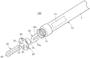
図1は、本発明に従う、非平面加熱チャンバー分離機構付きの移植可能な血管閉塞装置送達システムの分解図である。送達システム100は、近位端部5及び遠位端部15を有する前進部材又はプッシャー10を含む。実例として、送達システム100が図に示され、カテーテルベースの送達システムがこの図に記載されている。塞栓コイルのような移植可能な血管閉塞装置60が、ポリマー分離ファイバ45を介して、前進部材10の遠位端部15に取り付けられる。本発明の送達システムは、塞栓コイルに限定されず、別の移植可能な血管閉塞装置とともに使用されてもよいことに留意すべきである。
FIG. 1 is an exploded view of an implantable vascular occlusion device delivery system with a non-planar heating chamber separation mechanism according to the present invention. The
前進部材10は、送達カテーテルのルーメン内に嵌合するのに十分な小直径のものであり、軸方向力を遠位に伝えるのに十分な円柱強度を有しつつ、同時に蛇行する解剖学的構造を進むのに十分な可撓性を有することが好ましい。前進部材10は、以下の属性、すなわち、中空通路であることと、導電性であることと、複合層又は非均質材特性を備えることと、のうちの1つ又は2つ以上を有してもよいが、有しなくてもよい。前進部材10の遠位端部15の近傍に、非平面加熱チャンバー、ボウル又は皿20がある。実例として、図に示す加熱チャンバー20は、放物形を有している。楕円又は円錐のような任意の非平面形状が想定されて本発明の範囲内にあるが、それらの形状には限定されない。前進部材10の遠位端部15から見ると、加熱チャンバー20は、凹形、ボウル又は非平面皿の形状を形成する。加熱チャンバー20の内面は、前進部材10の遠位端部15から離れる方を向き、一方、その外面は、前進部材10の遠位端部15を向いている。円柱状チューブ又は頸部25が、加熱チャンバー20のボウル又は非平面皿の外面のほぼ中心にあり、それから突き出ている。加熱チャンバー20は、中に、画定された中央開口部23を有し、頸部25の全長に長手方向に延在することにより、それを通る通路又はチャネルを形成する。拡大された非平面カラー40が、加熱チャンバー20の中央開口部23から半径方向外側に延在している。非平面カラー40の外径は、頸部25の外径より大きく、一方、頸部25の外径は、前進部材10の遠位端部15の内径内に受け取られる程十分に小さいことが好ましい。頸部25は、プレス嵌め方法、(例えば、噛合いねじ部を介する)機械的方法、又は接着剤を介する方法を含む任意の方法で、前進部材内に固定されてもよいが、これらに限定されない。
The advancing
1つ又は2つ以上の電熱器要素/線50を長手方向に前進部材10を通してその近位端部5に向かって後方に導入する/捩じ込む/編み込むために、1つ又は2つ以上の孔又は開口部30が、非平面カラー40を通して長手方向に画定されてもよい。図に示す例示的な実施形態では、非平面カラー40は、5つの孔又は開口部30を有するが、これは、所望により、任意の数の開口部を含むように変更されてもよい。複数の開口部30は、加熱チャンバー20上の加熱ワイヤ又は要素50の数及び配列を適合又は変更させることを可能にする。代替として、開口部30は、全体として除かれるか、又は数を減らされてもよく、それによって、加熱線/要素50は、加熱チャンバー20の内面に永久的に取り付けられるか又は組み込まれる。有利なことに、これは、平面カラー40に画定される開口部の数を制限することなく、加熱要素の数を増やすことを可能にする。更に、平面カラー40に画定された開口部を除去するか又は数を減らすことにより、熱を集中させるためにより大きな乱れていない表面積が提供される。
One or more electric heater elements /
加熱線/要素50の数は、所望により、少なくとも1つ又は2つ以上の加熱線/要素50が選択されてもよい。2つの電熱線/要素50であれば、分離ファイバ45に沿った2つの異なる場所において、熱を生成することになる。3つの電熱線/要素50であれば、分離ファイバ45に沿った3つの異なる場所において熱を生成する、などになる。2つ以上の加熱線/要素50であれば、より大きな熱エネルギー及び/又は異なる時間に複数の場所において(例えば、2つの分離ファイバ45に対して)熱エネルギーを供給する能力を提供する。更に、2つ以上の加熱線/要素50であれば、また、有利なことに、標的部位での信頼性の高い塞栓コイルの分割又は分離を保証する。より大きい熱エネルギーは、非平面の加熱チャンバー20の開口角度(すなわち、角度が中央開口部23の中心点から非平面カラーの外縁まで描かれた、相互に180°離れた2つの半径に対応する角度)、及び/又は深さ(すなわち、中央開口部23の中心点から非平面カラー40の外縁までの距離)を低減することによって保持され得る。
As for the number of heating lines /
図1に示す例示的な実施形態を参照すると、U字形状の加熱線/要素50のそれぞれの自由端部50aは、非平面カラー40を通して長手方向に画定された2つの開口部30(好ましくは、2つの隣接した開口部)内に受け取られる。加熱線50の自由端部50aは、好ましくは、頸部25の外側に前進部材10の完全な長手方向長さではなくとも、少なくとも一部分を通ってその近位端部5に向かって延在し、加熱線を励起させることにより熱を生成する電気エネルギーを提供する電源55に、電気線又はリードを介して電気接続される。好ましくは、電源は人体の外部にあり、しかし、人体の内部にある(充電式又は非充電式の)(例えば、送達システム100自体の内部に配置された)バッテリーが、代替として使用されてもよい。電源の種類、(人体の内部又は外部の)場所、数は、エネルギーが加熱線/要素50を励起することにより熱を生成するように提供される限り、所望により、変更されてもよい。加熱線/要素50のそれぞれに供給されるエネルギーは、それぞれの独立した加熱線/要素がそれぞれの異なる電源に接続され得るので、ほぼ同一であってもよく、さもなければ、所望により、変更されてもよい。
Referring to an exemplary embodiment shown in FIG. 1, each
前進部材10は、血管閉塞装置60(例えば塞栓コイル)に分離ファイバ45を介して固定され、この分離ファイバは、好ましくは、ポリマー材料、例えば、ポリエチレン、ポリプロピレン、又は熱によって溶かすことができる任意の別の比較的薄く押出し可能なポリマーでできている。図示する例示的な分離ファイバ45は、塞栓コイル60に固定又は連結された、拡大された閉鎖遠位端部46を有するU字形状繊維である。例えば、分離ファイバ45の自由端部45aのうちの1つは、塞栓コイル60の近位端部に配置された固定部材65(例えばリング)を通して捩じ込まれて拡大された閉鎖端部46によって中に固定される。分離ファイバ45の自由端部45aは、開口部23及び前進部材10を通ってその近位端部5に向かって後方に延在し、一方、拡大された閉鎖端部46は、中央開口部23と係合することによりそれを通過することを防止する。分離ファイバ45は、機械的手段、摩擦又は接着剤によって前進部材10の通路/ルーメンの内部に固定されてもよい。
The advancing
加熱チャンバーの非平面形状は、多数の利点、例えば、(i)関節点を、閉塞装置の近位端部と送達システムの遠位端部との間に提供すること(図5を参照)、(ii)蛇行性のヒト解剖学的構造を通って送達/前進させられる間、閉塞装置が常に自動的に中心に戻る作用が維持されること、及び(iii)閉塞装置を送達システムから分離することに必要なエネルギーを最小にするために、分離ファイバと加熱要素/線との間に常に物理的接触を維持することを有する。 The non-planar shape of the heating chamber provides a number of advantages, eg, (i) an articular point between the proximal end of the obstruction device and the distal end of the delivery system (see Figure 5). (Ii) The obstruction device is always maintained to automatically return to the center while being delivered / advanced through the tortuous human anatomical structure, and (iii) the obstruction device is separated from the delivery system. In particular, it has to maintain physical contact between the separation fiber and the heating element / wire in order to minimize the energy required.
移植可能な血管閉塞装置送達システムのための本発明の分離機構は、身体全体に及ぶ多様な多数の医学上の障害の治療に好適である。しかし、脳の障害を治療することに関連する困難のために、本発明の分離システムは、周囲の脳組織への損傷を最小にする、分離ファイバを溶解/切断するのに必要な消費エネルギーを最小化することに特に有益である。 The separation mechanism of the present invention for implantable vascular occlusion device delivery systems is suitable for the treatment of a wide variety of medical disorders throughout the body. However, due to the difficulties associated with treating brain disorders, the separation system of the present invention consumes the energy required to dissolve / cut the separation fiber, minimizing damage to surrounding brain tissue. Especially useful for minimizing.
手術において、血管閉塞装置60(例えば塞栓コイル)を前進部材10上に組み立てる/据え付ける。分離ファイバ45の自由端部45aのうちの1つを、塞栓コイル60の近位端部の近傍に配置された固定部材65(例えばリング)を通過させる。例えば、分離ファイバ45は、ねじ付きであるか、ループ状であるか、フック状であるか、さもなければ、拡大された閉鎖端部46によってそこに固定された、塞栓コイル60のリング又は別の機械的な固定装置65を通過する。分離ファイバ45の自由端部45aを開口部23の中に及び前進部材10を通して挿入し、最終的に、その拡大された閉鎖端部46が開口部23に入ることなく、物理的に接触して静止する。前進部材10及びそれに一緒に固定された塞栓コイル60を送達カテーテル95の中に導入する。一旦組み立てられると、前進部材及び塞栓コイルとともに送達カテーテル95は、身体の中に導入されて、血管を通って標的部位まで移動する。閉塞装置60が身体内の標的部位に到達すると、前進部材10は、標的部位に配備されて、塞栓コイル60を送達カテーテル95から押し出す。加熱線50は、次に、電源55(身体の内部又は外部の)によって通電されて、分離ファイバ45を溶解又は切断する。切断された分離ファイバ45は、閉塞装置60がそれ自体を前進部材10から解放して、血管の中の標的部位に位置決めされた状態のままであることを可能にする。送達カテーテル95及び前進部材10は、次に、身体から引き出され得る一方、塞栓コイルは、標的部位で適所に留まる。
In surgery, the vascular occlusion device 60 (eg, embolic coil) is assembled / installed on the advancing
本発明の基本的な新規特徴をその好適な実施形態に適応するものとして図示、説明及び指示するが、示された装置の形状及び詳細、並びにそれらの操作の様々な省略、置換及び変更が、本発明の範囲及び趣旨から逸脱せずに当業者は実施できるであろうことが理解されよう。例えば、同じ結果を達成するために、実質的に同じ方法で、実質的に同じ機能を実行する要素及び/又は工程の全ての組合せは、本発明の範囲内であることが明らかである。また、説明されたひとつの実施形態から別の実施形態に要素を代用することも完全に意図され熟考されている。図面は必ずしも一定の比率の縮尺で描かれておらず、それらは本質的に概念的なものであることも理解されるべきである。したがって、添付の特許請求の範囲に示されたようにのみ、限定されることを意図する。 Although the basic novel features of the present invention are illustrated, described and indicated as adaptable to their preferred embodiments, the shapes and details of the devices shown, as well as various omissions, substitutions and modifications of their operations, are present. It will be appreciated that those skilled in the art will be able to carry out without departing from the scope and gist of the present invention. For example, it is clear that all combinations of elements and / or steps that perform substantially the same function in substantially the same way to achieve the same result are within the scope of the present invention. It is also fully intended and pondered to substitute elements from one embodiment described to another. It should also be understood that the drawings are not necessarily drawn to a certain ratio of scales and that they are conceptual in nature. Therefore, it is intended to be limited only as indicated in the appended claims.
本明細書に引用される全ての発行済み特許、係属中の特許出願、刊行物、論文、書籍、又は任意の他の参照文献はそれぞれ、その全文が参照することにより本明細書に組み込まれる。 All published patents, pending patent applications, publications, treatises, books, or any other references cited herein are incorporated herein by reference in their entirety.
〔実施の態様〕
(1) 移植可能な血管閉塞装置のための送達システムであって、
遠位端部及び反対側の近位端部を有する前進部材と、
前記前進部材の前記遠位端部の近傍に配置された非平面加熱チャンバーであって、前記非平面加熱チャンバーは、前記前進部材の前記遠位端部から離れる方を向く内面及び前記前進部材の前記遠位端部を向く反対側の外面を有する、非平面加熱チャンバーと、
ポリマー材料から作成され、前記非平面加熱チャンバーの前記内面から突き出ている閉鎖遠位端部を有する分離ファイバと、
前記非平面加熱チャンバーの前記内面に配置された少なくとも1つの加熱要素であって、前記少なくとも1つの加熱要素は、前記分離ファイバを切断するのに十分な熱を生成する、少なくとも1つの加熱要素と、
を備える、送達システム。
(2) 前記非平面加熱チャンバーは、放物線状の、楕円形状の、又は円錐形状の横方向断面を有する、実施態様1に記載の送達システム。
(3) 前記非平面加熱チャンバーは、それを通して長手方向に画定された少なくとも1つの開口部を有し、前記少なくとも1つの加熱要素は、前記少なくとも1つの開口部を通して捩じ込まれる、実施態様1に記載の送達システム。
(4) 前記非平面加熱チャンバーは、中に、画定された中央開口部を有する、実施態様1に記載の送達システム。
(5) 前記非平面加熱チャンバーは、前記外面から突き出ている頸部を有し、前記頸部は、前記分離部材の自由端部を受け取るために、中に、長手方向に画定されたチャネルを有する、実施態様4に記載の送達システム。
[Implementation mode]
(1) A delivery system for implantable vascular occlusion devices.
An advancing member with a distal end and a contralateral proximal end,
A non-planar heating chamber arranged in the vicinity of the distal end of the advancing member, wherein the non-planar heating chamber is an inner surface of the advancing member facing away from the distal end and of the advancing member. A non-planar heating chamber having an outer surface on the opposite side facing the distal end.
A separation fiber made of a polymeric material and having a closed distal end protruding from the inner surface of the non-planar heating chamber.
At least one heating element disposed on the inner surface of the non-planar heating chamber, wherein the at least one heating element and the at least one heating element generate enough heat to cut the separation fiber. ,
A delivery system.
(2) The delivery system according to embodiment 1, wherein the non-planar heating chamber has a parabolic, elliptical, or conical cross section.
(3) The non-planar heating chamber has at least one opening defined longitudinally through it, the at least one heating element being screwed through the at least one opening, embodiment 1. The delivery system described in.
(4) The delivery system according to embodiment 1, wherein the non-planar heating chamber has a defined central opening therein.
(5) The non-planar heating chamber has a neck protruding from the outer surface, the neck having a longitudinally defined channel therein to receive the free end of the separating member. The delivery system according to embodiment 4.
(6) 前記少なくとも1つの加熱要素に電気接続された電源を更に備える、実施態様1に記載の送達システム。
(7) 前記分離ファイバの前記閉鎖遠位端部は、前記分離ファイバの一部分が前記非平面加熱チャンバーの前記中央開口部を通過することを防止するように拡張されている、実施態様1に記載の送達システム。
(8) 物理的接触が、前記分離ファイバと前記少なくとも1つの加熱要素との間に常に維持されている、実施態様1に記載の送達システム。
(9) 移植可能な血管閉塞装置のための送達システムを組み立てる方法であって、前記送達システムは、遠位端部及び反対側の近位端部を有する前進部材と、前記前進部材の前記遠位端部の近傍に配置された非平面加熱チャンバーであって、前記非平面加熱チャンバーは、前記前進部材の前記遠位端部から離れる方を向く内面及び前記前進部材の前記遠位端部を向く反対側の外面を有する、非平面加熱チャンバーと、ポリマー材料から作成され、前記非平面加熱チャンバーの前記内面から突き出ている閉鎖遠位端部を有する分離ファイバと、前記非平面加熱チャンバーの前記内面に配置された少なくとも1つの加熱要素であって、前記少なくとも1つの加熱要素は、前記分離ファイバを切断するのに十分な熱を生成する、少なくとも1つの加熱要素と、を備え、前記方法は、
前記少なくとも1つの加熱要素を前記非平面加熱チャンバーの前記内面に位置決めする工程と、
前記非平面加熱チャンバーの前記外面を前記前進部材の前記遠位端部に固定する工程と、
前記分離ファイバの2つの終端自由端部のうちの一方を、前記血管閉塞装置に配置された固定部材を通して、前記固定部材が前記分離ファイバの前記閉鎖遠位端部に物理的に接触するまで捩じ込む工程と、
前記分離ファイバの前記2つの終端自由端部を前記血管閉塞装置とともに、前記前進部材の前記遠位端部に、その間に前記非平面加熱チャンバーが配置された状態で固定する工程であって、前記少なくとも1つの加熱要素は、前記分離ファイバを切断するのに十分な熱を生成するために、前記非平面加熱チャンバーの前記内面に配置されている、工程と、
を含む、方法。
(10) 前記少なくとも1つの加熱要素の数及び場所は、前記少なくとも1つの加熱要素を前記非平面加熱チャンバーを通して長手方向に画定された少なくとも1つの孔を通して捩じ込むことによって、再構成可能である、実施態様9に記載の方法。
(6) The delivery system according to embodiment 1, further comprising a power source electrically connected to the at least one heating element.
(7) The closed distal end of the separation fiber is extended to prevent a portion of the separation fiber from passing through the central opening of the non-planar heating chamber, according to embodiment 1. Delivery system.
(8) The delivery system according to embodiment 1, wherein physical contact is always maintained between the separation fiber and the at least one heating element.
(9) A method of assembling a delivery system for an implantable vaso-occlusive device, wherein the delivery system has a forward member having a distal end and a proximal end on the opposite side, and the far forward member of the forward member. A non-planar heating chamber arranged in the vicinity of the position end, wherein the non-planar heating chamber has an inner surface of the advancing member facing away from the distal end and the distal end of the advancing member. A non-planar heating chamber with an opposite outer surface, a separation fiber made from a polymer material and having a closed distal end protruding from the inner surface of the non-planar heating chamber, and said in the non-planar heating chamber. The method comprises at least one heating element disposed on the inner surface, said at least one heating element comprising at least one heating element, which produces sufficient heat to cut the separation fiber. ,
A step of positioning the at least one heating element on the inner surface of the non-planar heating chamber, and
A step of fixing the outer surface of the non-planar heating chamber to the distal end of the advancing member.
One of the two termination free ends of the separation fiber is threaded through a fixation member located in the vascular occlusion device until the fixation member physically contacts the closure distal end of the separation fiber. The process of squeezing and
A step of fixing the two end free ends of the separation fiber together with the vascular occlusion device to the distal end of the advance member in a state where the non-planar heating chamber is arranged between them. At least one heating element is located on the inner surface of the non-planar heating chamber to generate enough heat to cut the separation fiber.
Including methods.
(10) The number and location of at least one heating element can be reconfigured by screwing the at least one heating element through at least one hole defined longitudinally through the non-planar heating chamber. , The method according to
(11) 関節点が、前記血管閉塞装置の近位端部と前記送達システムの遠位端部との間に確立されている、実施態様9に記載の方法。
(12) 移植可能な血管閉塞装置を送達システムを用いて血管内の標的部位に位置決めする方法であって、前記送達システムが、遠位端部及び反対側の近位端部を有する前進部材と、前記前進部材の前記遠位端部の近傍に配置された非平面加熱チャンバーであって、前記非平面加熱チャンバーは、前記前進部材の前記遠位端部から離れる方を向く内面及び前記前進部材の前記遠位端部を向く反対側の外面を有する、非平面加熱チャンバーと、ポリマー材料から作成され、前記非平面加熱チャンバーの前記内面から突き出ている閉鎖遠位端部を有する分離ファイバと、前記非平面加熱チャンバーの前記内面に配置された少なくとも1つの加熱要素であって、前記少なくとも1つの加熱要素は、前記分離ファイバを切断するのに十分な熱を生成する、少なくとも1つの加熱要素と、を備え、前記方法が、
送達カテーテルを用いて前記送達システムを前記血管の中に導入する工程と、
前記送達カテーテルを前記血管を通して前記標的部位まで前進させる工程と、
前記血管の中の前記標的部位において、前記血管閉塞装置を前記送達カテーテルから突き出すために、前記前進部材を配備する工程と、
前記分離ファイバを切断することにより前記血管の中の標的部位において前記血管閉塞装置を解放するのに十分な熱を生成するために、前記少なくとも1つの加熱要素を電源から通電する工程と、
前記血管閉塞装置を前記血管の中の前記標的部位に位置する状態に維持しつつ、中に配置された前記送達カテーテル及び前記前進部材を前記血管から摘出する工程と、
を含む、方法。
(13) 関節点が、前記血管閉塞装置の近位端部と前記送達システムの遠位端部との間に確立されている、実施態様12に記載の方法。
(14) 前記血管閉塞装置は、前進させられる間、常に自動的に中心にあるままである、実施態様12に記載の方法。
(11) The method of
(12) A method of positioning an implantable vaso-occlusive device at a target site within a blood vessel using a delivery system, wherein the delivery system is associated with an advancing member having a distal end and a contralateral proximal end. , A non-planar heating chamber arranged in the vicinity of the distal end of the advancing member, wherein the non-planar heating chamber is an inner surface of the advancing member facing away from the distal end and the advancing member. A non-planar heating chamber having an outer surface facing the distal end of the non-planar heating chamber and a separating fiber having a closed distal end protruding from the inner surface of the non-planar heating chamber. At least one heating element disposed on the inner surface of the non-planar heating chamber, wherein the at least one heating element and the at least one heating element generate sufficient heat to cut the separation fiber. , And the above method
The step of introducing the delivery system into the blood vessel using a delivery catheter, and
A step of advancing the delivery catheter through the blood vessel to the target site,
A step of deploying the advance member in order to project the vascular occlusion device from the delivery catheter at the target site in the blood vessel.
A step of energizing the at least one heating element from a power source in order to generate sufficient heat to release the vascular occlusion device at a target site in the blood vessel by cutting the separation fiber.
A step of removing the delivery catheter and the advancing member arranged therein from the blood vessel while maintaining the vascular occlusion device in a state of being located at the target site in the blood vessel.
Including methods.
(13) The method of embodiment 12, wherein the articulated point is established between the proximal end of the vascular occlusion device and the distal end of the delivery system.
(14) The method of embodiment 12, wherein the vascular occlusion device remains automatically central at all times while being advanced.
Claims (11)
遠位端部及び反対側の近位端部を有する前進部材と、
前記前進部材の前記遠位端部の近傍に配置された非平面加熱チャンバーであって、前記非平面加熱チャンバーは、前記前進部材の前記遠位端部から離れる方を向く内面及び前記前進部材の前記遠位端部を向く反対側の外面を有する、非平面加熱チャンバーと、
ポリマー材料から作成され、前記非平面加熱チャンバーの前記内面から突き出ている閉鎖遠位端部を有する分離ファイバと、
前記非平面加熱チャンバーの前記内面に配置された少なくとも1つの加熱要素であって、前記少なくとも1つの加熱要素は、前記分離ファイバを切断するのに十分な熱を生成する、少なくとも1つの加熱要素と、
を備える、送達システム。 A delivery system for implantable vascular occlusion devices,
An advancing member with a distal end and a contralateral proximal end,
A non-planar heating chamber arranged in the vicinity of the distal end of the advancing member, wherein the non-planar heating chamber is an inner surface of the advancing member facing away from the distal end and of the advancing member. A non-planar heating chamber having an outer surface on the opposite side facing the distal end.
A separation fiber made of a polymeric material and having a closed distal end protruding from the inner surface of the non-planar heating chamber.
At least one heating element disposed on the inner surface of the non-planar heating chamber, wherein the at least one heating element and the at least one heating element generate enough heat to cut the separation fiber. ,
A delivery system.
前記少なくとも1つの加熱要素を前記非平面加熱チャンバーの前記内面に位置決めする工程と、
前記非平面加熱チャンバーの前記外面を前記前進部材の前記遠位端部に固定する工程と、
前記分離ファイバの2つの終端自由端部のうちの一方を、前記血管閉塞装置に配置された固定部材を通して、前記固定部材が前記分離ファイバの前記閉鎖遠位端部に物理的に接触するまで捩じ込む工程と、
前記分離ファイバの前記2つの終端自由端部を前記血管閉塞装置とともに、前記前進部材の前記遠位端部に、その間に前記非平面加熱チャンバーが配置された状態で固定する工程であって、前記少なくとも1つの加熱要素は、前記分離ファイバを切断するのに十分な熱を生成するために、前記非平面加熱チャンバーの前記内面に配置されている、工程と、
を含む、方法。 A method of assembling a delivery system for an implantable vaso-occlusive device, wherein the delivery system has a forward member having a distal end and a contralateral proximal end, and the distal end of the forward member. A non-planar heating chamber located in the vicinity of, wherein the non-planar heating chamber is an inner surface facing away from the distal end of the advancing member and the opposite side of the advancing member facing the distal end. Arranged on the inner surface of the non-planar heating chamber, with a non-planar heating chamber having an outer surface, and a separation fiber made from a polymer material and having a closed distal end protruding from the inner surface of the non-planar heating chamber. The method comprises at least one heating element, wherein the at least one heating element generates sufficient heat to cut the separation fiber.
A step of positioning the at least one heating element on the inner surface of the non-planar heating chamber, and
A step of fixing the outer surface of the non-planar heating chamber to the distal end of the advancing member.
One of the two termination free ends of the separation fiber is threaded through a fixation member located in the vascular occlusion device until the fixation member physically contacts the closure distal end of the separation fiber. The process of squeezing and
A step of fixing the two end free ends of the separation fiber together with the vascular occlusion device to the distal end of the advance member in a state where the non-planar heating chamber is arranged between them. At least one heating element is located on the inner surface of the non-planar heating chamber to generate enough heat to cut the separation fiber.
Including methods.
Applications Claiming Priority (2)
| Application Number | Priority Date | Filing Date | Title |
|---|---|---|---|
| US14/971,474 US10188395B2 (en) | 2015-12-16 | 2015-12-16 | Non-planar heating chamber detachment mechanism of an implantable vaso-occluding device delivery system |
| US14/971,474 | 2015-12-16 |
Publications (2)
| Publication Number | Publication Date |
|---|---|
| JP2017109098A JP2017109098A (en) | 2017-06-22 |
| JP6855231B2 true JP6855231B2 (en) | 2021-04-07 |
Family
ID=57570189
Family Applications (1)
| Application Number | Title | Priority Date | Filing Date |
|---|---|---|---|
| JP2016243256A Active JP6855231B2 (en) | 2015-12-16 | 2016-12-15 | Non-planar heating chamber separation mechanism for implantable vascular occlusion delivery system |
Country Status (8)
| Country | Link |
|---|---|
| US (1) | US10188395B2 (en) |
| EP (1) | EP3181065B1 (en) |
| JP (1) | JP6855231B2 (en) |
| KR (1) | KR20170072148A (en) |
| CN (1) | CN106880386B (en) |
| AU (1) | AU2016269497A1 (en) |
| BR (1) | BR102016029479A2 (en) |
| CA (1) | CA2950938A1 (en) |
Families Citing this family (1)
| Publication number | Priority date | Publication date | Assignee | Title |
|---|---|---|---|---|
| DE102022117911A1 (en) * | 2022-07-18 | 2024-01-18 | Standard Instruments GmbH Gesellschaft für Medizintechnik, Mess- und Regeltechnik, Steuerungstechnik | Connection cable and detachment device |
Family Cites Families (19)
| Publication number | Priority date | Publication date | Assignee | Title |
|---|---|---|---|---|
| US5108407A (en) | 1990-06-08 | 1992-04-28 | Rush-Presbyterian St. Luke's Medical Center | Method and apparatus for placement of an embolic coil |
| US5989242A (en) | 1995-06-26 | 1999-11-23 | Trimedyne, Inc. | Therapeutic appliance releasing device |
| US5911737A (en) | 1997-02-28 | 1999-06-15 | The Regents Of The University Of California | Microfabricated therapeutic actuators |
| US6102917A (en) | 1998-07-15 | 2000-08-15 | The Regents Of The University Of California | Shape memory polymer (SMP) gripper with a release sensing system |
| US6478773B1 (en) | 1998-12-21 | 2002-11-12 | Micrus Corporation | Apparatus for deployment of micro-coil using a catheter |
| US7608058B2 (en) | 2002-07-23 | 2009-10-27 | Micrus Corporation | Stretch resistant therapeutic device |
| US7789891B2 (en) | 2003-09-23 | 2010-09-07 | Boston Scientific Scimed, Inc. | External activation of vaso-occlusive implants |
| JP4879025B2 (en) * | 2004-10-29 | 2012-02-15 | 株式会社カネカ | Medical wire |
| US20060271097A1 (en) * | 2005-05-31 | 2006-11-30 | Kamal Ramzipoor | Electrolytically detachable implantable devices |
| US7591833B2 (en) | 2005-06-30 | 2009-09-22 | Codman & Shurtleff, Inc. | Laser-based vascular occlusion device detachment system |
| ES2526417T3 (en) * | 2008-09-09 | 2015-01-12 | Boston Scientific Scimed, Inc. | Mechanisms of detachment of composite material |
| US20100160903A1 (en) | 2008-12-22 | 2010-06-24 | Yosef Krespi | Process and system for treating a vascular occlusion or other endoluminal structure |
| US20100160944A1 (en) | 2008-12-24 | 2010-06-24 | Boston Scientific Scimed, Inc. | Thermally detachable embolic assemblies |
| US20120253381A1 (en) * | 2011-03-31 | 2012-10-04 | Codman & Shurtleff, Inc. | Occlusive device with porous structure and stretch resistant member |
| US8920459B2 (en) * | 2012-03-30 | 2014-12-30 | DePuy Synthes Products, LLC | Embolic coil detachment mechanism with flexible distal member and resistive electrical heating element |
| US9980731B2 (en) | 2012-03-30 | 2018-05-29 | DePuy Synthes Products, Inc. | Embolic coil detachment mechanism with flexible distal member and coupling union |
| US9155540B2 (en) * | 2012-03-30 | 2015-10-13 | DePuy Synthes Products, Inc. | Embolic coil detachment mechanism with heating element and kicker |
| US9451964B2 (en) | 2013-03-14 | 2016-09-27 | Stryker Corporation | Vaso-occlusive device delivery system |
| JP6359664B2 (en) | 2013-08-20 | 2018-07-18 | ストライカー コーポレイションStryker Corporation | Vascular occlusive device delivery system |
-
2015
- 2015-12-16 US US14/971,474 patent/US10188395B2/en not_active Expired - Fee Related
-
2016
- 2016-12-08 AU AU2016269497A patent/AU2016269497A1/en not_active Withdrawn
- 2016-12-08 CA CA2950938A patent/CA2950938A1/en not_active Abandoned
- 2016-12-14 KR KR1020160170137A patent/KR20170072148A/en active IP Right Grant
- 2016-12-15 EP EP16204280.8A patent/EP3181065B1/en active Active
- 2016-12-15 JP JP2016243256A patent/JP6855231B2/en active Active
- 2016-12-15 BR BR102016029479A patent/BR102016029479A2/en not_active Application Discontinuation
- 2016-12-16 CN CN201611167109.XA patent/CN106880386B/en not_active Expired - Fee Related
Also Published As
| Publication number | Publication date |
|---|---|
| KR20170072148A (en) | 2017-06-26 |
| US20170172579A1 (en) | 2017-06-22 |
| US10188395B2 (en) | 2019-01-29 |
| CN106880386A (en) | 2017-06-23 |
| CA2950938A1 (en) | 2017-06-16 |
| EP3181065A1 (en) | 2017-06-21 |
| BR102016029479A2 (en) | 2017-06-20 |
| CN106880386B (en) | 2021-05-18 |
| JP2017109098A (en) | 2017-06-22 |
| EP3181065B1 (en) | 2020-07-29 |
| AU2016269497A1 (en) | 2017-07-06 |
Similar Documents
| Publication | Publication Date | Title |
|---|---|---|
| US20240081829A1 (en) | Delivery and detachment systems and methods for vascular implants | |
| KR102299607B1 (en) | Embolic coil detachment mechanism with flexible distal member and coupling union | |
| EP3253302B1 (en) | Detachable implantable devices | |
| JP4884943B2 (en) | Embolization device delivery system | |
| JP2018532532A (en) | Mechanical embolic delivery device and method | |
| US20230021694A1 (en) | Dissection rupture occlusion system | |
| AU2015227530B2 (en) | A vasculature occlusion device detachment system with tapered corewire and heater activated fiber detachment | |
| JP6918880B2 (en) | Vascular obstruction device detachment system with tapered core wire and heater activated fiber detachment | |
| CN108135619B (en) | Medical device delivery system | |
| JP6855231B2 (en) | Non-planar heating chamber separation mechanism for implantable vascular occlusion delivery system | |
| AU2015227527A1 (en) | A vasculature occlusion device detachment system with tapered corewire and heater activated fiber detachment | |
| US20200129185A1 (en) | In-vivo indwelling instrument and in-vivo indwelling instrument delivering system |
Legal Events
| Date | Code | Title | Description |
|---|---|---|---|
| A621 | Written request for application examination |
Free format text: JAPANESE INTERMEDIATE CODE: A621 Effective date: 20191029 |
|
| A977 | Report on retrieval |
Free format text: JAPANESE INTERMEDIATE CODE: A971007 Effective date: 20201019 |
|
| A131 | Notification of reasons for refusal |
Free format text: JAPANESE INTERMEDIATE CODE: A131 Effective date: 20201027 |
|
| A521 | Written amendment |
Free format text: JAPANESE INTERMEDIATE CODE: A523 Effective date: 20210120 |
|
| TRDD | Decision of grant or rejection written | ||
| A01 | Written decision to grant a patent or to grant a registration (utility model) |
Free format text: JAPANESE INTERMEDIATE CODE: A01 Effective date: 20210216 |
|
| A61 | First payment of annual fees (during grant procedure) |
Free format text: JAPANESE INTERMEDIATE CODE: A61 Effective date: 20210317 |
|
| R150 | Certificate of patent or registration of utility model |
Ref document number: 6855231 Country of ref document: JP Free format text: JAPANESE INTERMEDIATE CODE: R150 |