JP6855080B2 - Light emitting device and its light emitting control method - Google Patents
Light emitting device and its light emitting control method Download PDFInfo
- Publication number
- JP6855080B2 JP6855080B2 JP2019148901A JP2019148901A JP6855080B2 JP 6855080 B2 JP6855080 B2 JP 6855080B2 JP 2019148901 A JP2019148901 A JP 2019148901A JP 2019148901 A JP2019148901 A JP 2019148901A JP 6855080 B2 JP6855080 B2 JP 6855080B2
- Authority
- JP
- Japan
- Prior art keywords
- light emitting
- button
- light
- unit
- color
- Prior art date
- Legal status (The legal status is an assumption and is not a legal conclusion. Google has not performed a legal analysis and makes no representation as to the accuracy of the status listed.)
- Active
Links
- 238000000034 method Methods 0.000 title description 45
- 239000003086 colorant Substances 0.000 claims description 23
- 230000004044 response Effects 0.000 claims description 7
- 235000006040 Prunus persica var persica Nutrition 0.000 claims description 4
- 240000006413 Prunus persica var. persica Species 0.000 claims 1
- 230000008569 process Effects 0.000 description 38
- 230000006870 function Effects 0.000 description 10
- 238000010586 diagram Methods 0.000 description 4
- 244000144730 Amygdalus persica Species 0.000 description 3
- 230000008859 change Effects 0.000 description 3
- 230000005540 biological transmission Effects 0.000 description 2
- 230000010354 integration Effects 0.000 description 2
- 229920003023 plastic Polymers 0.000 description 2
- 239000011347 resin Substances 0.000 description 2
- 229920005989 resin Polymers 0.000 description 2
- 239000013589 supplement Substances 0.000 description 2
- 230000009471 action Effects 0.000 description 1
- 230000004397 blinking Effects 0.000 description 1
- 238000004891 communication Methods 0.000 description 1
- 238000006073 displacement reaction Methods 0.000 description 1
- 230000004048 modification Effects 0.000 description 1
- 238000012986 modification Methods 0.000 description 1
- 239000004065 semiconductor Substances 0.000 description 1
Images


Landscapes
- Circuit Arrangement For Electric Light Sources In General (AREA)
Description
本発明は、発光装置およびその発光制御方法に関するものである。 The present invention relates to a light emitting device and a light emitting control method thereof.
近年、携帯型ライトであって、ライト本体の特定方向への振り動作による変位に応じて、特定方向への振り動作に関連付けられた発光色へ変更する携帯型ライトがある(特許文献1参照)。 In recent years, there is a portable light that changes to a light emitting color associated with a swinging motion in a specific direction according to a displacement of the light body due to a swinging motion in a specific direction (see Patent Document 1). ..
一方で、棒状ライトであって、所定の順番で色選択ボタンを押下するごとに色表示ボタンに表示される色が変化し、色表示ボタンを押下すると、色表示ボタンに表示された色で光源部を発光させる棒状ライトもある(特許文献2参照)。 On the other hand, in a bar-shaped light, the color displayed on the color display button changes each time the color selection button is pressed in a predetermined order, and when the color display button is pressed, the light source is the color displayed on the color display button. There is also a rod-shaped light that emits light (see Patent Document 2).
ところで、上記特許文献1の携帯型ライトの場合、特定の振り動作をしなければ、所望の色に変更できないとともに、その特定の振り動作と発光色の対応関係を記憶しておかないと所望の発光色に変更できないユーザにとって使い勝手が悪いという問題がある。 By the way, in the case of the portable light of Patent Document 1, it is not possible to change to a desired color without performing a specific swinging motion, and it is desirable to remember the correspondence between the specific swinging motion and the emission color. There is a problem that it is not easy to use for users who cannot change the emission color.
また、上記特許文献2に示す棒状ライトの場合、色表示ボタンに表示される所望の色になるまで、場合によっては複数回色選択ボタンを押下しないと、所望の色での発光ができないという問題があった。
Further, in the case of the rod-shaped light shown in
そこで、本発明は上記問題に鑑みて成されたものであり、従来よりも簡単に所望の色で発光させることができる発光装置を提供することを目的とする。 Therefore, the present invention has been made in view of the above problems, and an object of the present invention is to provide a light emitting device capable of emitting light in a desired color more easily than before.
上記課題を解決するために、本発明の一態様に係る発光装置は、発光部と、発光部を発光させる複数の色の発光順序を定める所定の順序を示す情報を記憶する記憶部と、発光部を発光させる複数の色を、所定の順序で切り替える第1ボタンと、複数の色の中から1つの色を推薦色として設定する設定部と、推薦色で発光部を発光させるための入力を受け付ける第2ボタンと、第1ボタンに対するユーザからの第1所定入力に応じて、所定の順序に従って、複数の色のうちいずれか1つの色で発光部を発光させ、第2ボタンに対するユーザからの第1所定入力に応じて所定の順序に関わらず推薦色で発光部を発光させる発光制御部と、を備える。 In order to solve the above problems, the light emitting device according to one aspect of the present invention includes a light emitting unit, a storage unit that stores information indicating a predetermined order that determines a light emitting order of a plurality of colors that cause the light emitting unit to emit light, and a light emitting unit. The first button that switches between multiple colors that make the unit emit light in a predetermined order, the setting unit that sets one color from multiple colors as the recommended color, and the input for making the light emitting unit emit light with the recommended color. In response to the second button to be accepted and the first predetermined input from the user to the first button, the light emitting unit is made to emit light in any one of a plurality of colors according to a predetermined order, and the light emitting unit is emitted from the user to the second button. A light emitting control unit that emits light in a recommended color according to a first predetermined input regardless of a predetermined order is provided.
上記課題を解決するために、本発明の一態様に係る発光制御方法は、発光部と、発光部を発光させる複数の色の発光順序を定める所定の順序を示す情報を記憶する記憶部と、第1ボタンと、第2ボタンとを備える発光装置の発光制御方法であって、複数の色の中から1つの色を推薦色として設定する設定ステップと、第1ボタンに対するユーザからの第1所定入力に応じて、所定の順序に従って、複数の色のうちいずれか1つの色で発光部を発光させる第1発光制御ステップと、第2ボタンに対するユーザからの第1所定入力に応じて、所定の順序に関わらず推薦色で発光部を発光させる第2発光制御ステップとを含む。 In order to solve the above problems, the light emission control method according to one aspect of the present invention includes a light emitting unit, a storage unit that stores information indicating a predetermined order for determining the light emission order of a plurality of colors that cause the light emitting unit to emit light, and a storage unit. A method of controlling light emission of a light emitting device including a first button and a second button, which is a setting step of setting one color from a plurality of colors as a recommended color, and a first predetermined setting from a user for the first button. In response to the input, the first light emission control step of causing the light emitting unit to emit light in any one of the plurality of colors according to a predetermined order, and the first predetermined input from the user to the second button are predetermined. It includes a second light emission control step of causing the light emitting unit to emit light in the recommended color regardless of the order.
上記装置において、発光部を発光させる複数の色を、所定の順序とは逆順に切り替える第3ボタンを備え、発光制御部は、第2ボタンに対するユーザからの第1所定入力に応じて、所定の順序の逆順に従って、複数の色のうちいずれか1つの色で発光部を発光させることとしてもよい。 The device includes a third button that switches a plurality of colors that cause the light emitting unit to emit light in the reverse order of the predetermined order, and the light emission control unit receives a predetermined input from the user for the second button. The light emitting unit may be made to emit light in any one of a plurality of colors according to the reverse order of the order.
上記装置において、設定部は、さらに、複数の色の中からユーザの所望する発光順序を示す発光パターンを設定し、記憶部は、さらに、発光パターンを示す情報を記憶し、発光装置は、さらに、発光パターンと、所定の順序とのいずれかを選択する選択部を備え、発光制御部は、選択部において選択されている発光パターンで示される発光順序または所定の順序のいずれかで示される順序に従い、第1ボタンに対するユーザからの入力又は第2ボタンに対するユーザからの第1所定入力に従って、複数の色の中のうちいずれか1つの色で発光部を発光させることとしてもよい。 In the above device, the setting unit further sets a light emitting pattern indicating a light emitting order desired by the user from a plurality of colors, the storage unit further stores information indicating the light emitting pattern, and the light emitting device further stores information indicating the light emitting pattern. , A selection unit for selecting either a light emission pattern and a predetermined order, and the light emission control unit is an order indicated by either the light emission order indicated by the light emission pattern selected in the selection unit or the predetermined order. According to this, the light emitting unit may be made to emit light in any one of a plurality of colors according to the input from the user for the first button or the first predetermined input from the user for the second button.
上記装置において、記憶部は、発光パターン及び所定の順序それぞれを示す発光色を示す情報記憶し、選択部は、発光部が発光していない場合であって、第3ボタン又は第1ボタン及び第3ボタン双方に対する第2所定入力があったときには、発光パターンで示される発光順序又は所定の順序で示される発光順序の中から発光順序の選択を開始し、発光制御部は、発光順序の選択中において、発光パターンまたは所定の順序のいずれかを示す発光色を発光部に発光させるとともに、第1ボタンに対するユーザからの入力に従って、発光パターンまたは所定の順序のいずれかを示す発光色を切り替え、選択部は、発光順序の選択中において、第1ボタン又は第3ボタンに対するユーザからの第2所定入力があった場合に、その時に発光部が発光している発光色に対応する発光パターンまたは所定の順序を、発光制御の発光順序として選択することとしてもよい。 In the above device, the storage unit stores information indicating a light emitting pattern and a light emitting color indicating each of a predetermined order, and the selection unit is a case where the light emitting unit does not emit light, and the third button or the first button and the third button. When there is a second predetermined input for both of the three buttons, selection of the light emission order is started from the light emission order shown by the light emission pattern or the light emission order shown in the predetermined order, and the light emission control unit is selecting the light emission order. In the light emitting unit, a light emitting color indicating either a light emitting pattern or a predetermined order is made to emit light, and a light emitting color indicating either a light emitting pattern or a predetermined order is switched and selected according to an input from a user to the first button. When the user receives a second predetermined input for the first button or the third button during the selection of the light emission order, the unit is a light emission pattern or a predetermined light emission pattern corresponding to the light emission color emitted by the light emitting unit at that time. The order may be selected as the light emission order of the light emission control.
上記装置において、選択部は、発光順序の選択中において、第1ボタン及び第3ボタン双方に対する第2所定入力に従って、その時に発光部が発光している発光色に対応する発光パターンを記憶部から削除することとしてもよい。 In the above device, the selection unit receives a light emission pattern corresponding to the light emission color emitted by the light emitting unit at that time from the storage unit according to the second predetermined input to both the first button and the third button during the selection of the light emission order. It may be deleted.
上記装置において、設定部は、発光装置が発光していない場合であって、第3ボタン又は第1ボタン及び第3ボタン双方に対する第2所定入力があったときには、発光パターンの設定を開始し、発光パターンの設定中に、設定部は、第1ボタンに対するユーザからの第1所定入力に従って、発光部を発光させている発光色を発光パターンの1つの発光色として記憶し、発光パターンの設定中に、発光制御部は、第3ボタンに対するユーザからの第1所定入力に従って、発光部を発光させている発光色を切り替え、発光パターンの設定中に、設定部は、第1ボタン又は第3ボタンに対するユーザからの第2所定入力に従って、それまでに記憶した発光色を、記憶した順序を発光順序とした発光パターンを記憶部に記憶することとしてもよい。 In the above device, the setting unit starts setting the light emitting pattern when the light emitting device is not emitting light and there is a second predetermined input to both the third button or the first button and the third button. While setting the light emission pattern, the setting unit stores the light emission color causing the light emission unit to emit light as one light emission color of the light emission pattern according to the first predetermined input from the user to the first button, and is setting the light emission pattern. In addition, the light emission control unit switches the light emission color that causes the light emission unit to emit light according to the first predetermined input from the user to the third button, and while the light emission pattern is being set, the setting unit uses the first button or the third button. In accordance with a second predetermined input from the user to the above, the emission color stored up to that point may be stored in the storage unit as an emission pattern in which the stored order is the emission order.
上記装置において、発光装置は、棒状ライトであることとしてもよい。 In the above device, the light emitting device may be a rod-shaped light.
本発明の一態様に係る発光装置は、特定のボタンに対して特定の色を設定することによって、ボタンの押下一つで所望の色の発光を行うことができる。 By setting a specific color for a specific button, the light emitting device according to one aspect of the present invention can emit light of a desired color with a single button press.
以下、本発明の一実施態様に係る発光装置について、図面を参照しながら詳細に説明する。 Hereinafter, the light emitting device according to one embodiment of the present invention will be described in detail with reference to the drawings.
<実施の形態>
<構成>
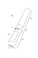
図1は、発光装置100の外観を示す外観図である。図1に示すように発光装置100は一例として棒状ライトであるが、発光装置100の形状は棒状に限るものではない。
<Embodiment>
<Structure>
FIG. 1 is an external view showing the appearance of the
発光装置100は、図1に示すように、発光部120と、把持部140とが、接続部130を介して接続されて成る。
As shown in FIG. 1, the
発光部120は、発光する機能を有する。発光部120は、発光部120自身が発光することしてもよいし、あるいは、接続部130部分に発光体を設け、そこから投射された光が、発光部120を透過して発光するという態様をとってもよい。発光部120は、例えば、筒状の透明なプラスチック内部に、光を透過かつ拡散する装飾シートを設け、接続部130部分に設けられた様々な色で発光する発光体からの光を拡散して、周囲に光を投光する構成であってもよい。発光体としては、発光ダイオードやLEDなどである。また、あるいは、発光部120は、筒状の透明な樹脂内部にLEDシートをその発光面を外部に向けて設けた構成により実現することとしてもよい。
The
接続部130は、発光部120と、把持部140とを接続する接続部材である。接続部130は、例えば、ねじ止め構造や、係止部材等により発光部120と把持部とを接続する構成であってもよい。発光部120と把持部140とを接続する手法としては、様々な従来の態様を用いてもよい。
The connecting
把持部140は、ユーザが発光装置100を把持する部材である。把持部140は、ユーザが発光装置100を把持可能に構成されていればどのような形態をとってもよい。把持部140は、接続部130とは、一体に成型されることとしてもよい。
The
把持部140は、第1ボタン111と、第2ボタン112と、第3ボタン113とを備える。第1ボタン111、第2ボタン112、第3ボタン113とは、例えば、プラスチックなどの樹脂により構成され、押下可能に構成されている。図1には図示していないが、第1ボタン111、第2ボタン112、第3ボタン113各々は、それぞれ、発光装置100の発光や発光のための制御に係る操作を受け付けるものである。ここでは、各ボタンは、押下型のボタンであるとしているが、これはその限りではなく、各ボタンは、ユーザからの入力を受け付ける機能を有するものであればよい。例えば、各ボタンは、タッチセンサにより実現されてもよい。
The
把持部140は、発光装置100を動作させるための電源(図示せず)を内部に有する。把持部140は、当該電源を取り外し可能に構成され、電源カバー150を外すことによって、電源の出し入れを実現できる。電源カバー150は、把持部140に対して取り付け自在に構成される。電源カバー150の把持部140への取り付け方は、どのような取り付け方であってもよく、例えば、把持部140に対してねじ止めにより取り付けられてもよいし、あるいは、例えば、鉤爪型の部材により係合してもよい。
The
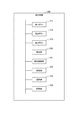
図2は、発光装置100の構成例を示すブロック図である。図2に示すように、発光装置100は、第1ボタン111と、第2ボタン112と、第3ボタン113と、発光部120と、発光制御部121と、設定部122と、選択部123と、記憶部124とを備える。
FIG. 2 is a block diagram showing a configuration example of the
第1ボタン111は、ユーザが押下可能なボタンである。第1ボタン111は、短押し(所定時間以上継続しない押下)と、長押し(所定時間以上継続した押下)の双方を検出可能なボタンである。 The first button 111 is a button that can be pressed by the user. The first button 111 is a button capable of detecting both a short press (press that does not continue for a predetermined time or longer) and a long press (press that continues for a predetermined time or longer).
第2ボタン112は、ユーザが押下可能なボタンである。第2ボタン112は、短押し(所定時間以上継続しない押下)と、長押し(所定時間以上継続した押下)の双方を検出可能なボタンである。
The
第3ボタン113は、ユーザが押下可能なボタンである。第3ボタン113は、短押し(所定時間以上継続しない押下)と、長押し(所定時間以上継続した押下)の双方を検出可能なボタンである。
The
発光部120は、複数の色の中から指定された色で発光する。発光部120は、例えば、発光ダイオードやLEDにより実現される。発光部120は、発光制御部121からの指示に従って、発光する。
The
発光制御部121は、発光部120の発光制御を行う機能を有する。発光制御部121は、発光部120が発光しているとき、発光していないとき、発光パターンの設定中、発光パターンの選択中など様々な状況において、第1ボタン111に対する短押し、長押し、第2ボタン112に対する短押し、長押し、第3ボタン113に対する短押し、長押しの押下内容に応じた発光部120の発光処理を行う機能を有する。発光制御部121は、発光部120を発光させている場合に、選択されている発光パターンに関わらず、第2ボタン112の押下を検出して、設定部122により記憶部124に設定された推薦色で発光部120を発光させる。発光制御部121による発光処理の詳細については、図4〜図6に示すフローチャートを参照して後述する。
The light emitting
設定部122は、発光パターンの設定を行う機能を有する。第1ボタン111又は第1ボタン111と第3ボタン113双方の長押しを検出したことを契機として、発光パターンの設定処理を実行する。設定部122による発光パターンの設定処理の詳細については、図6に示すフローチャートを参照して後述する。
The
また、設定部122は、発光部120の発光中に発光パターンの順序に関わらずユーザの所望する色で発光させるための推薦色を設定する機能を有する。設定部122は、発光部120が発光しているときに、ユーザからの第2ボタン112の長押しを検出した場合には、そのとき発光部120が発光している発光色を推薦色として、記憶部124に記憶する。
Further, the
選択部123は、記憶部124に記憶されている発光パターンのうち、用いる発光パターンを選択する機能を有する。選択部123は、第1ボタン111又は第1ボタン111と第3ボタン113双方の長押しを検出したことを契機として、発光パターンの選択処理を実行する。選択部123による発光パターンの選択処理の詳細については、図6に示すフローチャートを参照して後述する。
The
発光制御部121、設定部122、選択部123各々は、プロセッサにより実現され、当該プロセッサが記憶部124に記憶されているプログラムを実行することにより、上述の発光制御、設定処理、選択処理を実現する。なお、発光制御部121、設定部122、選択部123は、1つのプロセッサにより実現されてもよいし、複数のプロセッサにより実現されてもよい。
Each of the light
記憶部124は、発光装置100が動作上必要とする各種プログラムやデータを記憶する機能を有する記憶媒体である。記憶部124は、例えば、HDD、SSD、フラッシュメモリ、RAM、ROM等により実現される。記憶部124は、発光制御に係る発光制御プログラム、発光パターンの設定に係る設定プログラム、発光パターンの選択に係る選択プログラムなどのプログラムや、設定した発光パターンを示す発光パターン情報300、推薦色として設定した発光色を記憶している。
以上が発光装置100の構成である。
The
The above is the configuration of the
<データ>
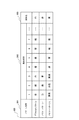
図3は、発光装置100の記憶部124に記憶されている発光パターン情報300のデータ構成例を示すデータ概念図である。
<Data>
FIG. 3 is a data conceptual diagram showing a data configuration example of the light
図3に示すように、発光パターン情報300は、パターン名称301と、発光順序302とが対応付けられた情報である。発光パターン情報300は、発光装置100の発光部120に発光する発光色を規定する情報である。
As shown in FIG. 3, the light
パターン名称301は、発光パターンを発光装置100が一意に特定可能な識別情報である。ここでは、パターン名称301は、わかりやすくするために名称で示しているが、パターン名称301は、他の発光パターンと区別できればよく、数字や記号などであらわされてもよい。
The
発光順序302は、発光部120を発光させる発光色の順番を示す情報である。発光順序302は、発光の順番を示す番号と、その番号に対応付けられる色を示しており、例えば、発光パターンの一つであるデフォルトパターンの場合には、「赤、紺、白、橙、緑、紫、桃、…」という順序を順方向として、発光装置100を発光することを示している。発光装置100は、順方向で発光する場合には、デフォルトパターンの場合であれば、上述の順番で発光し、逆順で発光する場合には、デフォルトパターンに桃以降の色が設定されていないとして、「赤、桃、紫、緑、橙、白、紺、赤、…」というように発光する。また、発光順序として番号に対して色が設定されないこともあり、その場合、図3の例では、「−」で示している。この発光順序は、先頭色の色である1番の色と、発光順序の最後の色はループしている。即ち、図8に示すように、発光パターンの一つであるメモリーパターン1の場合であれば、発光部120が発光しているときに第1ボタン111を短押しするごとに、「白、緑、青、白、緑、青、白、…」というように発光色が変更される。
The
識別色303は、発光パターンを選択する際に、ユーザが現在どの発光パターンを選択しようとしているのかを認識させるために、各発光パターンに固有に対応付けられた発光色を示す情報である。即ち、発光パターンを選択する際に、例えば、赤色が発光している場合には、メモリーターン1が選択状態にあることを示す。
The
<動作>
ここから、発光装置100の動作を説明する。図4は、発光装置100の動作例を示すメインフローチャートである。図4に示すフローチャートは、発光装置100が発光していない状態から開始する処理である。
<Operation>
From here, the operation of the
発光装置100は、第1ボタン111、第2ボタン112、第3ボタン113の少なくとも1つに対する入力があるか否かを、いずれかのボタンがユーザにより押下されたか否かに応じて判定する(ステップS401)。入力があった場合には(ステップS401のYES)、ステップS402に移行し、入力がない場合には(ステップS401のNO)、入力があるまで待機する。
The
入力が、第1ボタン111の長押しであった場合には(ステップS402のYES)、発光制御部121は、ステップS403に示す発光制御処理を開始する。発光制御処理の詳細については、後述する。発光制御部121が発光制御処理を終了すると、ステップS401に戻る。
When the input is a long press of the first button 111 (YES in step S402), the light
入力が、第1ボタン111に対する長押しではなく(ステップS402のNO)、第1ボタン111と第3ボタン113双方の長押しであった場合には(ステップS404のYES)には、設定部122又は選択部123は、ステップS406に示す発光パターンの設定/選択処理を開始する。発光パターンの設定/選択処理の詳細については、後述する。発光パターンの設定/選択処理を終了すると、ステップS401に戻る。
If the input is not a long press on the first button 111 (NO in step S402) but a long press on both the first button 111 and the third button 113 (YES in step S404), the
入力が、第1ボタン111と第3ボタン113との双方の長押しでなくとも(ステップS404のNO)、第3ボタン113に対する長押しであった場合には(ステップS405のYES)にも、設定部122又は選択部123による、発光パターンの設定/選択処理を開始する。
Even if the input is not a long press of both the first button 111 and the third button 113 (NO in step S404), but a long press of the third button 113 (YES in step S405), The light emission pattern setting / selection process by the
それ以外の場合には(ステップS405のNO)には、何らかの操作を行うための入力ではないので、ステップS401に戻る。 In other cases (NO in step S405), since it is not an input for performing some operation, the process returns to step S401.
以上が、発光装置100の動作のメインフローチャートの説明である。
The above is the description of the main flowchart of the operation of the
ここから、メインフローチャートに含まれる発光制御処理について説明する。 From here, the light emission control process included in the main flowchart will be described.
図5は、図4のメインフローチャート中のステップS403で示される発光制御処理の詳細を示すサブフローチャートである。 FIG. 5 is a sub-flow chart showing details of the light emission control process shown in step S403 in the main flowchart of FIG.
発光装置100の第1ボタン111が長押しされたことを受けて、図5に示すように、発光制御部121は、記憶部124に記憶されている選択中の発光パターンに関する情報から、選択されている発光パターンを特定する。そして、発光制御部121は、特定した発光パターンの先頭色(発光順序の1番目の発光色)で発光部120を発光させる(ステップS501)。
In response to the long press of the first button 111 of the
設定部122は、第2ボタン112が長押しされたか否かを、第2ボタン112が所定時間(例えば、3秒)以上押下されていたか否かに基づいて判定する(ステップS502)。第2ボタン112が長押しされていた場合には(ステップS502のYES)、設定部122は、その時に発光部120が発光している発光色を、推薦色として記憶部124に設定して(ステップS503)、ステップS502に戻る。
The
第2ボタン112が長押しされていなかった場合には(ステップS502のNO)、発光制御部121は、第1ボタン111が短押しされているか否かを、第1ボタン111が押下され、その押下時間が所定時間以上になっていないことに基づいて判定する(ステップS504)。第1ボタン111が短押しされていた場合には(ステップS504のYES)、発光制御部121は、発光部120を発光させている発光色を、選択状態にある発光パターンの発光順序で示される次の色の発光色に切り替えて(ステップS505)、ステップS502に戻る。
If the
第1ボタン111の短押しがなかった場合には(ステップS504のNO)、発光制御部121は、第3ボタン113が短押しされているか否かを判定する(ステップS506)。第3ボタン113が短押しされていた場合には(ステップS506のYES)、発光制御部121は、発光部120を発光させている発光色を、選択状態にある発光パターンの発光順序の逆順での次の色(順方向で1つ前の色)の発光色に切り替えて(ステップS507)、ステップS502に戻る。
If the first button 111 is not short-pressed (NO in step S504), the light
第3ボタン113の短押しがなかった場合には(ステップS506のNO)、発光制御部121は、第2ボタン112が短押しされているか否かを判定する(ステップS508)。第2ボタン112が短押しされていた場合には(ステップS508のYES)、記憶部124において、推薦色として設定されている発光色で発光部120を発光させ、ステップS502に戻る。
If the
第2ボタン112の短押しがなかった場合には(ステップS508のNO)、発光制御部121は、第1ボタン111が長押しされているか否かを判定する(ステップS510)。第1ボタン111が長押しされていなかった場合には(ステップS510のNO)、ステップS502に戻り、第1ボタン111が長押しされていた場合には(ステップS510のYES)、発光制御部121は、発光部120による発光を停止させて(ステップS511)、発光制御処理を終了する。
If the
以上が、発光装置100の発光制御に係る処理である。
The above is the process related to the light emission control of the
最後に、発光パターンの設定、選択処理についての動作を説明する。図6は、図4のメインフローチャート中のステップS406における発光パターン設定/選択処理の詳細を示すサブフローチャートである。 Finally, the operation of the light emission pattern setting and selection process will be described. FIG. 6 is a sub-flow chart showing details of the light emission pattern setting / selection process in step S406 in the main flowchart of FIG.
発光パターンの設定/選択処理を開始すると、発光制御部121は、押下されたボタンの内容(第3ボタン113の長押し(図4、ステップS404参照)、第1ボタン111と第3ボタン113双方の長押し(図4、ステップS405参照))に応じて、それぞれに対応付けられた発光色で発光部120を点滅させる(ステップS601)。
When the light emission pattern setting / selection process is started, the light
選択部123は、第2ボタン112の短押しがあったか否かを判定する(ステップS602)。
The
第2ボタン112の短押しがあった場合には(ステップS602のYES)、選択部123は、選択状態にある発光パターンを別の発光パターンに変更する。当該変更に応じて、発光制御部121は、変更後の発光パターンに対応する発光色で発光部120を発光させる。
When the
選択部123は、第1ボタン111又は第3ボタン113のいずれかの長押しがあったか否かを判定する(ステップS604)。
The
第1ボタン111又は第3ボタン113のいずれかの長押しがあった場合には(ステップS604のYES)、その時に発光部120が発光している発光色に対応する発光パターンを選択した発光パターン(使用する発光パターン)として、記憶部124に登録して(ステップS605)、処理を終了する。
When either the first button 111 or the
第1ボタン111又は第3ボタン113のいずれかの長押しがなかった場合には(ステップS604のNO)、設定部122は、第1ボタン111と第3ボタン113双方の長押しがあったか否かを判定する(ステップS606)。第1ボタン111と第3ボタン113双方の長押しがなかった場合には(ステップS606のNO)、ステップS602に戻り、第1ボタン111と、第3ボタン113双方の長押しがあった場合には(ステップS606のYES)、そのとき発光部120が発光している発光色に対応する発光パターンの発光順序の情報を、記憶部124の発光パターン情報300から削除して(ステップS607)、終了する。
If either the first button 111 or the
ステップS602において、第2ボタンの短押しがなかった場合に(ステップS602のNO)、第1ボタンの短押し、第3ボタンの短押し、第3ボタンの長押しのいずれかの入力に基づいて、発光パターンの設定を開始する。 In step S602, when there is no short press of the second button (NO in step S602), based on the input of any of the short press of the first button, the short press of the third button, and the long press of the third button. , Start setting the light emission pattern.
まず、発光制御部121は、第3ボタン113の短押しがあったか否かを判定する(ステップS608)。第3ボタン113の短押しがあった場合には(ステップS608のYES)、発光制御部121は、発光部120に発光させている発光色を発光パターン情報300のデフォルトパターンで示される発光順序の順に従って、発光色を切り替えて(ステップS609)、ステップS608に戻る。
First, the light
第3ボタン113の短押しがなかった場合には(ステップS608)、設定部122は、第1ボタン111の短押しがあったか否かを判定する(ステップS610)。第1ボタン111の短押しがあった場合には(ステップS610のYES)、設定部122は、発光部120が発光している発光色を発光パターンの次の発光色として記憶部124に記憶し(ステップS611)、ステップ608に戻る。
If the
第1ボタン111の短押しがなかった場合には(ステップS610のNO)、設定部122は、第3ボタン113の長押しがあったか否かを判定する(ステップS612)。
If the first button 111 is not short-pressed (NO in step S610), the
第3ボタン113の長押しがあった場合には(ステップS612)、その時点で、これまでにステップS611を経由した際に登録した発光色を、その登録した順序と同じ順番を発光順序とした発光パターンを、発光パターン情報300に新たに登録して(ステップS613)、終了する。第3ボタン113の長押しがなかった場合には(ステップS612のNO)、ステップS608に戻る。
When the
<まとめ>
発光装置100によれば、発光部120が所望の色で発光しているときに、第2ボタン112を長押しするだけで、推薦色として登録することができ、以降においては、使用している発光パターンの発光順序に関わりなく、第2ボタン112を短押しするだけで、いつでもユーザの望むタイミングで、推薦色で発光部120を発光させることができる。また、所望の色で発光しているときに第2ボタン112を長押しするだけで、新たに推薦色の登録しなおしも容易に行うことができる。さらには、発光装置100は、ユーザの所望の順序で発光する発光パターンを設定し、その発光パターンで発光色を切り替えて発光させたり、複数の発光パターンを登録して、その中から使用するものを自由に選択できたりするなどの多くの機能を、少ない入力数(ボタン数)で実現することができる。
<Summary>
According to the
<補足>
上記実施の形態に係る装置は、上記実施の形態に限定されるものではなく、他の手法により実現されてもよいことは言うまでもない。以下、各種変形例について説明する。
<Supplement>
Needless to say, the apparatus according to the above embodiment is not limited to the above embodiment, and may be realized by other methods. Hereinafter, various modification examples will be described.
(1)上記実施の形態においては、特に示さなかったが、発光装置100の発光制御部121は、発光部120を発光させる際に、常時発光、グラデーション発光、明滅発光等、様々な態様で発光させることとしてもよい。この場合、発光装置100は、3つのボタンの押下の組み合わせなどにより、その発光態様を変更できる構成をとってもよい。
(1) Although not particularly shown in the above embodiment, when the
(2)上記実施の形態においては、特に示していないが、推薦色で発光しているときに、第1ボタン111又は第3ボタン113の押下があった場合には、発光制御部121は、推薦色の前の色の発光に戻る構成を備えてもよい。
(2) Although not particularly shown in the above embodiment, if the first button 111 or the
(3)上記実施の形態において、各ボタン(第1ボタン111、第2ボタン112、第3ボタン113)に対する入力として短押しと、長押しとの2種類を提示しているが、これは、これに限定されるものではない。例えば、所定時間以内に2回押下することを検出し、その2回の押下をトリガとして、上述した何れかの処理のトリガとしてもよい。また、上記実施の形態に示した、短押しと長押しとを入れ替えても同様に動作させることができる。即ち、上述した第1所定入力を短押し、第2所定入力を長押しとしてもよいし、第1所定入力を長押し、第2所定入力を短押しとしてもよい。
(3) In the above embodiment, two types of inputs for each button (first button 111,
(4)上記実施の形態においては、推薦色として一色のみを設定する例を説明したが、推薦色は一色に設定する例を説明したが、これはその限りではない。推薦色は何色設定することとしてもよい。 (4) In the above embodiment, an example in which only one color is set as the recommended color has been described, but an example in which the recommended color is set to one color has been described, but this is not the case. Any number of recommended colors may be set.
当該構成を実現するために発光装置100は、2つ目、3つ目の第2ボタン112を備える構成としてもよい。そして、2つ目の第2ボタン112を長押しして2色目の推薦色を設定し、3つ目の第2ボタン112を長押しして3色目の推薦色を設定する。各第2ボタン112の押下されたボタンの短押しに応じて、対応付けられた推薦色を発光部120が発光する構成としてもよい。
In order to realize this configuration, the
あるいは、第2ボタン112と、第1ボタン111とを同時に長押しして、2色目の推薦色を設定し、第2ボタン112と、第3ボタン113とを同時に長尾押しして、3色目の推薦色を設定することとしてもよい。そして、第1ボタン111と第2ボタン112とを同時に短押しすることで、2色目の推薦色で発光部120を発光させ、第2ボタン112と第3ボタン113とを同時に短押しすることで、3色目の推薦色で発光部120を発光させる構成としてもよい。
Alternatively, press and hold the
(5)上記実施の形態においては、発光装置における推薦色を設定する手法として、装置のプロセッサが発光制御プログラム等を実行することにより、設定することとしているが、これは装置に集積回路(IC(Integrated Circuit)チップ、LSI(Large Scale Integration))等に形成された論理回路(ハードウェア)や専用回路によって実現してもよい。また、これらの回路は、1または複数の集積回路により実現されてよく、上記実施の形態に示した複数の機能部の機能を1つの集積回路により実現されることとしてもよい。LSIは、集積度の違いにより、VLSI、スーパーLSI、ウルトラLSIなどと呼称されることもある。 (5) In the above embodiment, as a method of setting the recommended color in the light emitting device, the processor of the device executes a light emitting control program or the like to set the recommended color, but this is set in the integrated circuit (IC) in the device. It may be realized by a logic circuit (hardware) or a dedicated circuit formed on a (Integrated Circuit) chip, an LSI (Large Scale Integration), or the like. Further, these circuits may be realized by one or a plurality of integrated circuits, and the functions of the plurality of functional units shown in the above-described embodiment may be realized by one integrated circuit. LSIs are sometimes called VLSIs, super LSIs, ultra LSIs, etc., depending on the degree of integration.
また、上記発光制御プログラムは、プロセッサが読み取り可能な記録媒体に記録されていてよく、記録媒体としては、「一時的でない有形の媒体」、例えば、テープ、ディスク、カード、半導体メモリ、プログラマブルな論理回路などを用いることができる。また、上記発光制御プログラムは、当該発光制御プログラムを伝送可能な任意の伝送媒体(通信ネットワークや放送波等)を介して上記プロセッサに供給されてもよい。本発明は、上記発光制御プログラムが電子的な伝送によって具現化された、搬送波に埋め込まれたデータ信号の形態でも実現され得る。 Further, the light emission control program may be recorded on a recording medium that can be read by a processor, and the recording medium may be a "non-temporary tangible medium" such as a tape, a disk, a card, a semiconductor memory, or a programmable logic. A circuit or the like can be used. Further, the light emission control program may be supplied to the processor via an arbitrary transmission medium (communication network, broadcast wave, etc.) capable of transmitting the light emission control program. The present invention can also be realized in the form of a data signal embedded in a carrier wave, in which the light emission control program is embodied by electronic transmission.
なお、上記発光制御プログラムは、例えば、Action Script、JavaScript(登録商標)などのスクリプト言語、Objective-C、Java(登録商標)などのオブジェクト指向プログラミング言語、HTML5などのマークアップ言語などを用いて実装できる。 The above light emission control program is implemented using, for example, a script language such as Action Script or JavaScript (registered trademark), an object-oriented programming language such as Objective-C or Java (registered trademark), or a markup language such as HTML5. it can.
(6)上記実施の形態に示した構成や、各補足に示した構成は、適宜組み合わせて実現することとしてもよい。 (6) The configuration shown in the above embodiment and the configuration shown in each supplement may be realized by appropriately combining them.
100 発光装置
111 第1ボタン
112 第2ボタン
113 第3ボタン
120 発光部
121 発光制御部
122 設定部
123 選択部
124 記憶部
130 接続部
140 把持部
150 電源カバー
100 Light emitting device 111
Claims (4)
前記発光部を発光させる複数の色のデフォルトの発光順序を定めるデフォルトパターンを記憶する記憶部と、
前記複数の色の中から1つの色を推薦色として設定する設定部と、
前記発光部を発光させる複数の色を、前記デフォルトパターンで示される発光順序で切り替える第1ボタンと、
前記推薦色で前記発光部を発光させるための入力を受け付ける第2ボタンと、
前記発光部を発光させる複数の色を、前記デフォルトパターンで示される発光順序とは逆順に切り替える第3ボタンと、
前記第1ボタン、前記第2ボタン、および前記第3ボタンが設けられ、内部に電源を有する把持部と、
前記デフォルトパターンで示される発光順序を選択する選択部を備え、
前記第1ボタンに対するユーザからの第1所定入力に応じて、前記選択部において選択されている前記デフォルトパターンで示される発光順序に従い、前記複数の色のうちいずれか1つの色で前記発光部を発光させる発光制御部と、を備え、
前記選択部は、
前記発光部が発光していない場合であって、少なくとも前記第3ボタンに対する第2所定入力があったときには、前記デフォルトパターンで示される発光順序を選択する発光装置。 Light emitting part and
A storage unit that stores a default pattern that determines a default light emission order for a plurality of colors that cause the light emitting unit to emit light, and a storage unit that stores the default pattern.
A setting unit that sets one color from the plurality of colors as a recommended color, and
A first button that switches a plurality of colors that make the light emitting unit emit light in the light emitting order shown by the default pattern, and
A second button that accepts an input for making the light emitting unit emit light with the recommended color, and
A third button that switches a plurality of colors that cause the light emitting unit to emit light in the reverse order of the light emission order shown in the default pattern.
A grip portion provided with the first button, the second button, and the third button and having a power supply inside, and a grip portion.
A selection unit for selecting the light emission order indicated by the default pattern is provided.
In response to the first predetermined input from the user to the first button, the light emitting unit is set to the light emitting unit with any one of the plurality of colors according to the light emitting order indicated by the default pattern selected in the selection unit. It is equipped with a light emission control unit that emits light.
The selection unit
A light emitting device that selects a light emitting order indicated by the default pattern when the light emitting unit does not emit light and at least when there is a second predetermined input to the third button.
ことを特徴とする請求項1又は2に記載の発光装置。 The light emitting device according to claim 1 or 2, wherein the light emitting device is a rod-shaped light.
The light emitting device according to any one of claims 1 to 3, wherein the light emitting color in the light emitting unit includes red, blue, navy blue, white, orange, green, purple, and peach.
Priority Applications (1)
| Application Number | Priority Date | Filing Date | Title |
|---|---|---|---|
| JP2019148901A JP6855080B2 (en) | 2019-08-14 | 2019-08-14 | Light emitting device and its light emitting control method |
Applications Claiming Priority (1)
| Application Number | Priority Date | Filing Date | Title |
|---|---|---|---|
| JP2019148901A JP6855080B2 (en) | 2019-08-14 | 2019-08-14 | Light emitting device and its light emitting control method |
Related Parent Applications (1)
| Application Number | Title | Priority Date | Filing Date |
|---|---|---|---|
| JP2016240332A Division JP6582357B2 (en) | 2016-12-12 | 2016-12-12 | Light emitting device and light emission control method thereof |
Related Child Applications (2)
| Application Number | Title | Priority Date | Filing Date |
|---|---|---|---|
| JP2019240065A Division JP6788300B2 (en) | 2019-12-30 | 2019-12-30 | Light emitting device and its light emitting control method |
| JP2020205719A Division JP7169001B2 (en) | 2020-12-11 | 2020-12-11 | bar light |
Publications (3)
| Publication Number | Publication Date |
|---|---|
| JP2019207887A JP2019207887A (en) | 2019-12-05 |
| JP2019207887A5 JP2019207887A5 (en) | 2020-03-19 |
| JP6855080B2 true JP6855080B2 (en) | 2021-04-07 |
Family
ID=68767835
Family Applications (1)
| Application Number | Title | Priority Date | Filing Date |
|---|---|---|---|
| JP2019148901A Active JP6855080B2 (en) | 2019-08-14 | 2019-08-14 | Light emitting device and its light emitting control method |
Country Status (1)
| Country | Link |
|---|---|
| JP (1) | JP6855080B2 (en) |
Family Cites Families (5)
| Publication number | Priority date | Publication date | Assignee | Title |
|---|---|---|---|---|
| JP2014199772A (en) * | 2013-03-29 | 2014-10-23 | 株式会社ルイファン・ジャパン | Rod-like lamp |
| JP6539033B2 (en) * | 2014-02-04 | 2019-07-03 | 株式会社ルイファン・ジャパン | Luminous body |
| JP5840252B2 (en) * | 2014-04-16 | 2016-01-06 | 株式会社ルミカ | Bar light |
| WO2016035836A1 (en) * | 2014-09-02 | 2016-03-10 | 株式会社ルイファン・ジャパン | Light adjustment system and light |
| JP2016165460A (en) * | 2015-03-02 | 2016-09-15 | 株式会社ゲートウェイアーチ | Fan |
-
2019
- 2019-08-14 JP JP2019148901A patent/JP6855080B2/en active Active
Also Published As
| Publication number | Publication date |
|---|---|
| JP2019207887A (en) | 2019-12-05 |
Similar Documents
| Publication | Publication Date | Title |
|---|---|---|
| US20210134144A1 (en) | System and method for simplified activity based setup of a controlling device | |
| JP6788300B2 (en) | Light emitting device and its light emitting control method | |
| US10049242B2 (en) | Information processing method and non-transitory recording medium | |
| US20150061539A1 (en) | Electronic device, computer program product, and control system | |
| US11404036B2 (en) | Communication method, sound generation method and mobile communication terminal | |
| JP2009246646A (en) | Remote control apparatus and setting method | |
| WO2015045706A1 (en) | Cooking assistance device, cooking assistance method, and cooking assistance system | |
| JP2014176080A (en) | Method for controlling illumination device and computer program thereof | |
| JP6582357B2 (en) | Light emitting device and light emission control method thereof | |
| JP6855080B2 (en) | Light emitting device and its light emitting control method | |
| KR102045618B1 (en) | Communication Apparatus with ID input method which is appropriate to numeral system | |
| JP2007114888A5 (en) | ||
| JP2021048139A (en) | Light-emitting device and light emission control method for the same | |
| CN108614448A (en) | Integrated tele-control system and computer readable recording medium storing program for performing | |
| EP2684109A1 (en) | A method, system and electronic device for association based identification | |
| US20080231492A1 (en) | System and method for application dependent universal remote control | |
| JP2022022841A (en) | Light-emitting device and light emission control method thereof | |
| JP2022034378A (en) | Light-emitting device | |
| CN108076282B (en) | Communication system and portable terminal | |
| JP2017223766A (en) | Display controller and control method for the same | |
| JP5072457B2 (en) | Remote controller and digital broadcast receiver | |
| KR100785668B1 (en) | Set-up method of total remocon | |
| CN104076764B (en) | Transmitter | |
| CN107896342A (en) | A kind of set top box displaying content switching method and device | |
| KR100861502B1 (en) | Mobile communication terminal and operating method thereof |
Legal Events
| Date | Code | Title | Description |
|---|---|---|---|
| A621 | Written request for application examination |
Free format text: JAPANESE INTERMEDIATE CODE: A621 Effective date: 20191205 |
|
| A521 | Request for written amendment filed |
Free format text: JAPANESE INTERMEDIATE CODE: A523 Effective date: 20200204 |
|
| A871 | Explanation of circumstances concerning accelerated examination |
Free format text: JAPANESE INTERMEDIATE CODE: A871 Effective date: 20200324 |
|
| A975 | Report on accelerated examination |
Free format text: JAPANESE INTERMEDIATE CODE: A971005 Effective date: 20200417 |
|
| A131 | Notification of reasons for refusal |
Free format text: JAPANESE INTERMEDIATE CODE: A131 Effective date: 20200421 |
|
| A601 | Written request for extension of time |
Free format text: JAPANESE INTERMEDIATE CODE: A601 Effective date: 20200615 |
|
| A521 | Request for written amendment filed |
Free format text: JAPANESE INTERMEDIATE CODE: A523 Effective date: 20200819 |
|
| A131 | Notification of reasons for refusal |
Free format text: JAPANESE INTERMEDIATE CODE: A131 Effective date: 20201013 |
|
| A521 | Request for written amendment filed |
Free format text: JAPANESE INTERMEDIATE CODE: A523 Effective date: 20201211 |
|
| TRDD | Decision of grant or rejection written | ||
| A01 | Written decision to grant a patent or to grant a registration (utility model) |
Free format text: JAPANESE INTERMEDIATE CODE: A01 Effective date: 20210302 |
|
| A61 | First payment of annual fees (during grant procedure) |
Free format text: JAPANESE INTERMEDIATE CODE: A61 Effective date: 20210310 |
|
| R150 | Certificate of patent or registration of utility model |
Ref document number: 6855080 Country of ref document: JP Free format text: JAPANESE INTERMEDIATE CODE: R150 |
|
| R250 | Receipt of annual fees |
Free format text: JAPANESE INTERMEDIATE CODE: R250 |