JP6854622B2 - Box for information distribution board - Google Patents

Box for information distribution board Download PDF

Info

Publication number
JP6854622B2
JP6854622B2 JP2016213443A JP2016213443A JP6854622B2 JP 6854622 B2 JP6854622 B2 JP 6854622B2 JP 2016213443 A JP2016213443 A JP 2016213443A JP 2016213443 A JP2016213443 A JP 2016213443A JP 6854622 B2 JP6854622 B2 JP 6854622B2
Authority
JP
Japan
Prior art keywords
base body
installation
power outlet
mounting plate
information
Prior art date
Legal status (The legal status is an assumption and is not a legal conclusion. Google has not performed a legal analysis and makes no representation as to the accuracy of the status listed.)
Active
Application number
JP2016213443A
Other languages
Japanese (ja)
Other versions
JP2017157818A (en
Inventor
三輪 修
三輪  修
大和 敬史
敬史 大和
Original Assignee
河村電器産業株式会社
Priority date (The priority date is an assumption and is not a legal conclusion. Google has not performed a legal analysis and makes no representation as to the accuracy of the date listed.)
Filing date
Publication date
Application filed by 河村電器産業株式会社 filed Critical 河村電器産業株式会社
Publication of JP2017157818A publication Critical patent/JP2017157818A/en
Application granted granted Critical
Publication of JP6854622B2 publication Critical patent/JP6854622B2/en
Active legal-status Critical Current
Anticipated expiration legal-status Critical

Links

Images

Description

本発明は、各種情報機器を収納した情報分電盤に使用される情報分電盤用箱体に関するものである。 The present invention relates to an information distribution board box used for an information distribution board containing various information devices.

従来、情報分電盤に使用される情報分電盤用箱体としては、後側に配置されるベース体と、ベース体の前側を覆うカバー体とを備えるとともに、情報機器を載置するための機器載置板をベース体に取り付けたものが考案されている(たとえば特許文献1)。そして、そのような情報分電盤用箱体のベース体には、一般的に、情報機器に接続されるケーブルを引き込むための引き込み口が設けられている。 Conventionally, the box body for the information distribution board used for the information distribution board includes a base body arranged on the rear side and a cover body covering the front side of the base body, and for mounting the information device. The device mounting plate of the above is attached to the base body (for example, Patent Document 1). The base body of such an information distribution board box is generally provided with a lead-in port for pulling in a cable connected to the information device.

特開2010−104073号公報Japanese Unexamined Patent Publication No. 2010-104073

情報分電盤用箱体内に設置される情報機器の種類や数が多くなると、引き込むケーブルの数も増えるため、どのケーブルをどの情報機器に接続すれば良いのか、ケーブルをどのように引き回せば配線がスムーズになるのか判別しにくい。しかしながら、従来の情報分電盤用箱体では、そのような問題に対応することができなかった。 As the types and number of information devices installed inside the information distribution board box increase, the number of cables to be pulled in also increases, so which cable should be connected to which information device and how to route the cables It is difficult to determine whether the wiring will be smooth. However, the conventional box for information distribution board cannot cope with such a problem.

そこで、本発明は、上記問題に鑑みなされたものであって、情報分電盤用箱体内でのケーブルの接続や引き回しを簡易に行うことができる情報分電盤用箱体を提供しようとするものである。 Therefore, the present invention has been made in view of the above problems, and an object of the present invention is to provide an information distribution board box body in which cables can be easily connected and routed inside the information distribution board box body. It is a thing.

上記目的を達成するために、本発明は、情報機器が搭載されるベース体と、前記ベース体の前側を覆うように組み付けられるカバー体と、前記情報機器の電源プラグを接続する電源コンセントとを有する情報分電盤用箱体であって、前記ベース体に、前記情報機器と接続されるケーブルを引き込むための引き込み口が設けられているとともに、前記引き込み口の開口縁に、前記ケーブル若しくは前記情報機器に関連する情報を表示するための表示部が設けられており、さらに、前記電源コンセントに係止片が設けられている一方、前記引き込み口の開口縁に、前記電源コンセントを設置するためのコンセント設置部として、前記係止片が係止可能な被係止部が設けられ、前記係止片を前記被係止部に係止させることにより、前記引き込み口の一部を覆うように前記電源コンセントが設置されることを特徴とする。 To achieve the above object, the present onset Ming, a base body information apparatus is mounted, and a cover body to be assembled so as to cover the front side of the base body, and a power outlet for connecting the power plug of the information equipment A box body for an information distribution board having the above, the base body is provided with a lead-in port for pulling in a cable connected to the information device, and the cable or the cable or the cable is provided at the opening edge of the lead-in port. A display unit for displaying information related to the information device is provided, and a locking piece is provided on the power outlet, while the power outlet is installed on the opening edge of the entrance. As an outlet installation portion for this purpose, a locked portion to which the locking piece can be locked is provided, and by locking the locking piece to the locked portion, a part of the entrance is covered. the power outlet you characterized in that it is installed on.

本発明によれば、ベース体に、情報機器と接続されるケーブルを引き込むための引き込み口が設けられているとともに、引き込み口の開口縁に、ケーブル若しくは情報機器に関連する情報を表示するための表示部が設けられているため、当該表示部を利用することで、引き込み口から引き込まれているケーブルが、どの情報機器に接続されるどのようなケーブルであるかといったことを容易に判別することができ、ケーブルの接続作業や引き回し作業等が簡易となる。
また、電源コンセントに係止片を設ける一方、引き込み口の開口縁に、電源コンセントを設置するためのコンセント設置部として、係止片が係止可能な被係止部を設け、係止片を被係止部に係止させることにより、引き込み口の一部を覆うように電源コンセントが設置されるようにしているため、ケーブルの引き込みには利用しない引き込み口を用いて電源コンセントを配置させることができる。したがって、情報分電盤用箱体内のスペースを効率良く使用することができ、情報分電盤用箱体内の設計自由度の向上等、使い勝手の一層の向上を図ることができる。
According to the present invention, the base body is provided with a lead-in port for pulling in a cable connected to the information device, and information related to the cable or the information device is displayed on the opening edge of the lead-in port. Since a display unit is provided, by using the display unit, it is possible to easily determine what kind of cable is connected to which information device and what kind of cable is being pulled in from the inlet. This makes it easier to connect cables and route them.
Moreover, while providing the locking piece into a power outlet, the opening edge of the service entrance, the outlet installation section for installing the power outlet, the locking piece is provided with a lockable engaged portion, the locking piece Is locked in the locked part so that the power outlet is installed so as to cover a part of the intake port. Therefore, the power outlet is arranged using the intake port that is not used for pulling in the cable. be able to. Therefore, the space inside the information distribution board box can be efficiently used, and the usability can be further improved, such as improving the degree of freedom in designing inside the information distribution board box.

情報分電盤の外観を示した斜視説明図である。It is a perspective explanatory view which showed the appearance of an information distribution board. ベース体からカバー体を取り外した状態を示した斜視説明図である。It is a perspective explanatory view which showed the state which the cover body was removed from the base body. ベース体から機器載置板を取り外した状態を示した斜視説明図である。It is a perspective explanatory view which showed the state which removed the device mounting plate from a base body. ベース体から電源コンセントを取り外した状態を示した斜視説明図である。It is a perspective explanatory view which showed the state which the power outlet was removed from the base body. 図4の状態にあるベース体を前側から示した説明図である。It is explanatory drawing which showed the base body in the state of FIG. 4 from the front side. 電源コンセントを示した斜視説明図である。It is a perspective explanatory view which showed the power outlet. 電源コンセントの説明図であり、(a)は上側から、(b)は前側から、(c)は右側から、(d)は下側から夫々示している。It is explanatory drawing of the power outlet, (a) is shown from the upper side, (b) is shown from the front side, (c) is shown from the right side, and (d) is shown from the lower side. 基台の説明図であり、(a)は前側から、(b)は右斜め上側から夫々示している。It is explanatory drawing of the base, (a) is shown from the front side, (b) is shown from the diagonally upper right side. 機器載置板から情報機器が取り除かれたベース体を示した斜視説明図である。It is a perspective explanatory view which showed the base body which information device was removed from the device mounting plate. 図9の状態にあるベース体を前側から示した説明図である。It is explanatory drawing which showed the base body in the state of FIG. 9 from the front side. 図10中のA−A線断面を示した説明図である。It is explanatory drawing which showed the cross section of line AA in FIG. 機器載置板の説明図であり、(a)は上側から、(b)は右斜め上側から、(c)は前側から、(d)は右側から夫々示している。It is explanatory drawing of the equipment mounting plate, (a) is shown from the upper side, (b) is shown from the diagonally upper right side, (c) is shown from the front side, and (d) is shown from the right side. 機器載置板をベース体に取り付ける様子を示した説明図である。It is explanatory drawing which showed the state of attaching the equipment mounting plate to a base body. 図9の状態から機器載置板の取付位置が変更されたベース体を示した説明図である。It is explanatory drawing which showed the base body which changed the mounting position of the device mounting plate from the state of FIG. 情報分電盤の断面を示した説明図である。It is explanatory drawing which showed the cross section of the information distribution board. 配線管を用いる様子を示した説明図である。It is explanatory drawing which showed the state of using a wiring pipe. 設置フレーム体が取り付けられたベース体を示した斜視説明図であり、(a)は設置フレーム体が閉姿勢にある状態を、(b)は設置フレーム体が開姿勢にある状態を夫々示している。It is a perspective explanatory view which showed the base body which attached the installation frame body, (a) shows the state which the installation frame body is in a closed posture, and (b) shows the state which the installation frame body is in an open posture, respectively. There is.

以下、本発明の一実施形態となる情報分電盤用箱体(以下、箱体と称す)について、図面にもとづき詳細に説明する。 Hereinafter, a box body for an information distribution board (hereinafter, referred to as a box body) according to an embodiment of the present invention will be described in detail with reference to the drawings.

図1は、情報分電盤1の外観を示した斜視説明図である。図2は、ベース体4からカバー体5を取り外した状態を示した斜視説明図である。図3は、ベース体4から機器載置板30を取り外した状態を示した斜視説明図である。図4は、ベース体4から電源コンセント20、20を取り外した状態を示した斜視説明図である。図5は、図4の状態にあるベース体4を前側から示した説明図である。図6は、電源コンセント20を示した斜視説明図である。図7は、電源コンセント20の説明図であり、(a)は上側から、(b)は前側から、(c)は右側から、(d)は下側から夫々示している。図8は、基台22の説明図であり、(a)は前側から、(b)は右斜め上側から夫々示している。図9は、機器載置板30から情報機器3が取り除かれたベース体4を示した斜視説明図である。図10は、図9の状態にあるベース体4を前側から示した説明図である。図11は、図10中のA−A線断面を示した説明図である。図12は、機器載置板30の説明図であり、(a)は上側から、(b)は右斜め上側から、(c)は前側から、(d)は右側から夫々示している。図13は、機器載置板30をベース体4に取り付ける様子を示した説明図である。図14は、図9の状態から機器載置板30の取付位置が変更されたベース体4を示した説明図である。図15は、情報分電盤1の断面を示した説明図である。図16は、配線管9、9・・を用いた様子を示した説明図である。図17は、設置フレーム体51、51が取り付けられたベース体4を示した斜視説明図であり、(a)は設置フレーム体51、51が閉姿勢にある状態を、(b)は設置フレーム体51、51が開姿勢にある状態を夫々示している。 
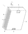
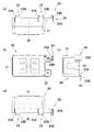
FIG. 1 is a perspective explanatory view showing the appearance of the information distribution board 1. FIG. 2 is a perspective explanatory view showing a state in which the cover body 5 is removed from the base body 4. FIG. 3 is a perspective explanatory view showing a state in which the device mounting plate 30 is removed from the base body 4. FIG. 4 is a perspective explanatory view showing a state in which the power outlets 20 and 20 are removed from the base body 4. FIG. 5 is an explanatory view showing the base body 4 in the state of FIG. 4 from the front side. FIG. 6 is a perspective explanatory view showing the power outlet 20. 7A and 7B are explanatory views of the power outlet 20, where FIG. 7A is shown from the upper side, FIG. 7B is shown from the front side, FIG. 7C is shown from the right side, and FIG. 7D is shown from the lower side. 8A and 8B are explanatory views of the base 22, in which FIG. 8A is shown from the front side and FIG. 8B is shown from the diagonally upper right side. FIG. 9 is a perspective explanatory view showing the base body 4 from which the information device 3 has been removed from the device mounting plate 30. FIG. 10 is an explanatory view showing the base body 4 in the state of FIG. 9 from the front side. FIG. 11 is an explanatory view showing a cross section taken along line AA in FIG. 12A and 12B are explanatory views of the device mounting plate 30, in which FIG. 12A is shown from the upper side, FIG. 12B is shown from the diagonally upper right side, FIG. 12C is shown from the front side, and FIG. 12D is shown from the right side. FIG. 13 is an explanatory view showing how the device mounting plate 30 is attached to the base body 4. FIG. 14 is an explanatory view showing the base body 4 in which the mounting position of the device mounting plate 30 is changed from the state of FIG. FIG. 15 is an explanatory view showing a cross section of the information distribution board 1. FIG. 16 is an explanatory diagram showing a state in which the wiring pipes 9, 9, ... Are used. 17A and 17B are perspective explanatory views showing a base body 4 to which the installation frame bodies 51 and 51 are attached. FIG. 17A is a state in which the installation frame bodies 51 and 51 are in a closed posture, and FIG. 17B is an installation frame. The bodies 51 and 51 are shown in the open posture, respectively.

情報分電盤1は、箱体2内に情報機器3等を収納してなるものであって、箱体2は、情報機器3等が搭載される板状のベース体4と、ベース体4の前側を覆うカバー体5とを備えている。カバー体5は、前面、左右両側面5a、5b、天面5c、及び底面5dを有して、後側に開口する箱状に形成されている。そして、カバー体5の前面の左右両側には、前面から夫々隣り合う側面5a、5bへ跨がるように把持部6、6が設けられている。また、カバー体5の左側面5aは、前方へ向かって右側へ傾斜する傾斜面とされており、右側面5bは、同様に、前方へ向かって左側へ傾斜する傾斜面とされている。また、天面5cは前方へ向かって下降する傾斜面とされており、底面5dは前方へ向かって上昇する傾斜面とされている。そして、天面5c、底面5dには通気によって蓋体2内の熱を逃がすための多数の通気孔7、7・・が穿設されている。 The information distribution board 1 is formed by storing the information device 3 and the like in the box body 2, and the box body 2 includes a plate-shaped base body 4 on which the information device 3 and the like are mounted and a base body 4. It is provided with a cover body 5 that covers the front side of the. The cover body 5 has a front surface, left and right side surfaces 5a and 5b, a top surface 5c, and a bottom surface 5d, and is formed in a box shape that opens to the rear side. Gripping portions 6 and 6 are provided on both left and right sides of the front surface of the cover body 5 so as to straddle the side surfaces 5a and 5b adjacent to each other from the front surface. Further, the left side surface 5a of the cover body 5 is an inclined surface that is inclined to the right side toward the front, and the right side surface 5b is similarly an inclined surface that is inclined to the left side toward the front. Further, the top surface 5c is an inclined surface that descends forward, and the bottom surface 5d is an inclined surface that rises forward. A large number of ventilation holes 7, 7, ... Are provided on the top surface 5c and the bottom surface 5d to release heat in the lid 2 by ventilation.

一方、ベース体4は、前後方向が厚み方向となる板状に形成されており、その中央部には、図示しない情報機器をネジ止めして設置可能な設置板11が備えられている。また、ベース体4には、電源コンセント20を設置するためのコンセント設置部15が複数箇所に設けられており、電源コンセント20の設置位置を選択可能となっている。さらに、ベース体4には、上面に情報機器3を載置可能な機器載置板30が、ベース体4から前側へ起立するような姿勢で取付可能となっている。そして、以上のような箱体2を有する情報分電盤1は、ベース体4を壁面等に固定した上で、設置板11にネジ止めしたり機器載置板30を利用したりして、必要な情報機器3をベース体4に設置し、最後にベース体4の前側にカバー体5を組み付けることで組み立て可能となっている。 On the other hand, the base body 4 is formed in a plate shape having a thickness direction in the front-rear direction, and an installation plate 11 to which an information device (not shown) can be screwed and installed is provided in the central portion thereof. Further, the base body 4 is provided with outlet installation portions 15 for installing the power outlet 20 at a plurality of locations, and the installation position of the power outlet 20 can be selected. Further, a device mounting plate 30 on which the information device 3 can be mounted can be mounted on the base body 4 in a posture of standing upright from the base body 4 to the front side. Then, in the information distribution board 1 having the box body 2 as described above, after fixing the base body 4 to a wall surface or the like, the base body 4 is screwed to the installation plate 11 or the equipment mounting plate 30 is used. It can be assembled by installing the necessary information device 3 on the base body 4 and finally assembling the cover body 5 on the front side of the base body 4.

ここで、電源コンセント20とベース体4における電源コンセント20の設置構造とについて説明する。
電源コンセント20は、基台22と、電源プラグを差し込み可能であり、基台22の前面にネジ止めされるコンセント本体21とからなる。基台22は、左右方向へ長い略方体状の合成樹脂製ブロック体であり、上面の左部と右部とには、後側(ベース体4側)へ延びる脚片23Aと、その先端上面に設けられ、上側へ突出する係止突部23Bとからなる係止片23が夫々設けられている。また、基台22の下面で、上面側の係止片23、23と対向する箇所にも、後側へ延びる脚片23Aと、その先端下面に設けられ、下側へ突出する係止突部23Bとからなる係止片23、23が夫々設けられている。さらに、基台22の上面で、右側の係止片23の更に右側には、右側へ延びて上下方向に弾性を有する弾性片24Aと、弾性片24Aの先端から後側へ突設された係合突部24Bとからなる係合部24が設けられている。一方、基台22の前面は略平坦に成形されており、その前面には、コンセント本体21をネジ止めするための複数のネジ孔25、25・・が設けられている。
Here, the installation structure of the power outlet 20 and the power outlet 20 in the base body 4 will be described.
The power outlet 20 includes a base 22 and an outlet body 21 into which a power plug can be inserted and screwed to the front surface of the base 22. The base 22 is a substantially rectangular synthetic resin block body that is long in the left-right direction, and the left and right parts of the upper surface are a leg piece 23A extending to the rear side (base body 4 side) and its tip. Each locking piece 23 is provided on the upper surface and is composed of a locking protrusion 23B protruding upward. Further, on the lower surface of the base 22, the leg pieces 23A extending to the rear side and the locking protrusions provided on the lower surface of the tip thereof and projecting downward are also provided at the positions facing the locking pieces 23 and 23 on the upper surface side. Locking pieces 23 and 23 made of 23B are provided, respectively. Further, on the upper surface of the base 22, on the right side of the locking piece 23 on the right side, an elastic piece 24A extending to the right and having elasticity in the vertical direction and a hook projecting from the tip of the elastic piece 24A to the rear side. An engaging portion 24 including a collision portion 24B is provided. On the other hand, the front surface of the base 22 is formed to be substantially flat, and a plurality of screw holes 25, 25, ... For screwing the outlet main body 21 are provided on the front surface thereof.

一方、ベース体4における設置板11の上側には、電線や通信線等といった情報機器に接続するケーブルを引き込むための2つの引き込み口12A、12Bを左右に並べてなる上引き込み部13Aが設けられている。また、設置板11の下側にも、2つの引き込み口12C、12Dを左右に並べてなる下引き込み部13Bが設けられている。さらに、上下の両引き込み部13A、13Bには、各引き込み口12A〜12Dの内側へ突出する設置リブ14、14が、引き込み口12A〜12Dの上縁及び下縁に沿って左右に延設されている。また、各設置リブ14の前後方向での位置は、各引き込み口12A〜12Dの後端よりも上記係止突部23Bの前後方向での厚みと略同じだけ前側となっている。そして、上下の両引き込み部13A、13Bにおける引き込み口12A〜12Dの開口縁であって、特に設置リブ14、14に、電源コンセント20を設置するためのコンセント設置部15が、夫々3箇所(左右両端部及び中央部)ずつ設けられている。 On the other hand, on the upper side of the installation plate 11 in the base body 4, an upper lead-in portion 13A is provided in which two lead-in ports 12A and 12B for drawing in cables connected to information devices such as electric wires and communication lines are arranged side by side. There is. Further, on the lower side of the installation plate 11, a lower pull-in portion 13B in which two lead-in ports 12C and 12D are arranged side by side is provided. Further, installation ribs 14 and 14 projecting inward of the lead-in ports 12A to 12D are extended to the left and right along the upper and lower edges of the lead-in ports 12A to 12D in both the upper and lower lead-in portions 13A and 13B. ing. Further, the positions of the installation ribs 14 in the front-rear direction are substantially the same as the thickness of the locking protrusions 23B in the front-rear direction from the rear ends of the lead-in ports 12A to 12D. Further, there are three outlet installation portions (left and right) for installing the power outlet 20 on the installation ribs 14 and 14, which are the opening edges of the inlets 12A to 12D in both the upper and lower intake portions 13A and 13B. Both ends and the center) are provided.

各コンセント設置部15は、4つの被係止部16、16・・と1つの被係合部17とを備えている。各被係止部16は、設置リブ14を係止突部23Bの左右幅と略同じ幅にわたって切り欠いた切り欠き部16Aと、切り欠き部16Aから左右へ係止突部23Bの左右幅と略同じ距離だけ離れた位置(なお、各コンセント設置部15毎に、切り欠き部16Aから右側へ離れるか、それとも左側へ離れるかは統一されている)において、設置リブ14の後面から後側へ立設された塞き止め面16Bとからなる。また、被係合部17は、設置リブ14の前面に設けられた凹部として形成されている。そして、各コンセント設置部15では、上側の設置リブ14に2つの被係止部16、16が左右に並んで設けられているとともに、下側の設置リブ14で上側の設置リブ14に設けられた被係止部16、16と対向する位置に、残り2つの被係止部16、16が左右に並んで設けられている。また、後述の如くして被係止部16、16・・に電源コンセント20の係止片23、23・・を係止させた際、電源コンセント20の係合部24に対応する位置に被係合部17が設けられている。なお、各設置リブ14における左右に並んだ被係止部16、16間の距離は、電源コンセント20における左右に並んだ係止片23、23間の距離と同じとなっている。 Each outlet installation portion 15 includes four locked portions 16, 16 ... And one engaged portion 17. Each locked portion 16 has a notch 16A in which the installation rib 14 is cut out over a width substantially the same as the left and right width of the locking protrusion 23B, and the left and right width of the locking protrusion 23B from the notch 16A to the left and right. At positions separated by approximately the same distance (note that it is unified whether each outlet installation portion 15 is separated from the notch 16A to the right or to the left) from the rear surface to the rear side of the installation rib 14. It is composed of an erected blocking surface 16B. Further, the engaged portion 17 is formed as a recess provided on the front surface of the installation rib 14. In each outlet installation portion 15, two locked portions 16 and 16 are provided side by side on the upper installation rib 14, and the lower installation rib 14 is provided on the upper installation rib 14. The remaining two locked portions 16, 16 are provided side by side at positions facing the locked portions 16, 16. Further, when the locking pieces 23, 23 ... Of the power outlet 20 are locked to the locked portions 16, 16 ... As described later, they are covered at the positions corresponding to the engaging portions 24 of the power outlet 20. An engaging portion 17 is provided. The distance between the left and right locked portions 16 and 16 in each installation rib 14 is the same as the distance between the left and right locking pieces 23 and 23 in the power outlet 20.

上述したような電源コンセント20をベース体4に設置するにあたっては、ベース体4に6箇所設けられているコンセント設置部15、15・・から適切なコンセント設置部15を選択する。そして、電源コンセント20の係止突部23B、23B・・を被係止部16、16・・の切り欠き部16A、16A・・にあてがい、後側へ押し込んで係止突部23B、23B・・を設置リブ14、14よりも後側へ位置させる。そして、そのまま電源コンセント20を、ベース体4の前面に沿って塞き止め面16B、16B・・側へ左側若しくは右側へスライドさせれば、係止突部23B、23B・・が設置リブ14の後側へ入り込んで、係止片23、23・・が被係止部16、16・・に係止する。また、このスライドにより、後側への押し込み時に弾性変形していた弾性片24Aが元の状態に復帰して係合突部24Bが被係合部17に係合し、係合部24が被係合部17に係合する。そして、この係止片23、23・・の被係止部16、16・・への係止、及び係合部24の被係合部17の係合をもって、電源コンセント20は、コンセント設置部15に固定されてベース体4に設置される。なお、当該設置状態において、電源コンセント20は引き込み口12A〜12Dの一部の前側を覆っている。 When installing the power outlet 20 as described above on the base body 4, an appropriate outlet installation unit 15 is selected from the outlet installation units 15, 15, ... Provided at six locations on the base body 4. Then, the locking protrusions 23B, 23B ... Of the power outlet 20 are applied to the notches 16A, 16A ... Of the locked portions 16, 16A ... -Position the installation ribs 14 and 14 behind. Then, if the power outlet 20 is slid to the left or right side of the blocking surfaces 16B, 16B ... along the front surface of the base body 4, the locking protrusions 23B, 23B ... Entering to the rear side, the locking pieces 23, 23 ... Lock the locked portions 16, 16 ... Further, by this slide, the elastic piece 24A elastically deformed when pushed to the rear side returns to the original state, the engaging protrusion 24B engages with the engaged portion 17, and the engaging portion 24 is covered. Engage with the engaging portion 17. Then, with the locking of the locking pieces 23, 23 ... To the locked portions 16, 16 ..., and the engagement of the engaged portion 17 of the engaging portion 24, the power outlet 20 becomes the outlet installation portion. It is fixed to 15 and installed on the base body 4. In the installed state, the power outlet 20 covers a part of the front side of the inlets 12A to 12D.

また、電源コンセント20の設置位置を変更したい場合には、設置状態にある電源コンセント20の係合部24の弾性片24Aを変形させ、係合突部24Bと被係合部17との係合を解除すればよい。すると、電源コンセント20の左右方向へのスライド(ベース体4の前面に沿ってのスライド)が可能となるため、電源コンセント20をスライドさせて係止片23、23・・と被係止部16、16・・との係止を解除すれば、電源コンセント20をベース体4から取り外すことができる。 Further, when it is desired to change the installation position of the power outlet 20, the elastic piece 24A of the engaging portion 24 of the power outlet 20 in the installed state is deformed, and the engaging protrusion 24B and the engaged portion 17 are engaged with each other. Should be released. Then, since the power outlet 20 can be slid in the left-right direction (sliding along the front surface of the base body 4), the power outlet 20 is slid to the locking pieces 23, 23 ... The power outlet 20 can be removed from the base body 4 by releasing the lock with the, 16.

なお、上引き込み部13Aからケーブルを引き込む際、図16に示すように、接続される情報機器毎に配線管9、9・・を分けて引き込むことで配線の接続作業や引き回し作業等が簡易となる。そして、配線管9、9・・の判別を容易とするために、ベース体4の引き込み口12A、12Bの上縁に沿って、ケーブルの種類、接続される情報機器等といったケーブル若しくは情報機器に関連する情報を表示するための名称表示部8、8・・が設けられている。 When the cable is pulled in from the upper pull-in portion 13A, as shown in FIG. 16, the wiring pipes 9, 9, ... Are separated for each information device to be connected, so that the wiring connection work and the wiring work can be simplified. Become. Then, in order to facilitate the discrimination of the wiring pipes 9, 9 ..., along the upper edges of the lead-in ports 12A and 12B of the base body 4, the cable or information device such as the type of cable and the information device to be connected is used. Name display units 8, 8, ... For displaying related information are provided.

次に、機器載置板30とベース体4における機器載置板30の取付構造とについて説明する。
機器載置板30は、上下方向が厚み方向となる合成樹脂製の板体であって、前部は情報機器3を載置する機器載置部として、後部はベース体4への取付部として夫々機能するようになっている。この機器載置部には、上下方向に貫通する多数の設置孔31、31・・が開設されている。そして、当該設置孔31、31・・を利用して、弾性を有するバンド部材(図示せず)を情報機器3に巻回させることで、機器載置部上で情報機器3を固定可能となっている。また、機器載置部の前端(機器載置板30の前端)には、機器載置部の上面よりも上側へ突出しており、情報機器3が機器載置部上から転落する事態を防止する転落防止壁32が設けられている。一方、取付部は、機器載置部よりも薄肉とされており、該取付部の上面における後端縁には、取付部の上面よりも上方へ突出しており、機器載置板30をベース体4に掛止するための掛止リブ33が、後端縁に沿って左右方向へ延設されている。また、取付部の下面における後端部は、後方へ向かって先細りするような傾斜面34として成形されている。さらに、取付部の下面には、取付部は勿論、機器載置部の下面よりも下方へ突出する支持リブ35が左右方向へ延設されている。
Next, the device mounting plate 30 and the mounting structure of the device mounting plate 30 on the base body 4 will be described.
The device mounting plate 30 is a plate made of synthetic resin whose vertical direction is the thickness direction, and the front portion serves as a device mounting portion on which the information device 3 is mounted, and the rear portion serves as a mounting portion on the base body 4. Each is designed to work. A large number of installation holes 31, 31 ... Penetrating in the vertical direction are provided in the device mounting portion. Then, the information device 3 can be fixed on the device mounting portion by winding the elastic band member (not shown) around the information device 3 by using the installation holes 31, 31 ... ing. Further, the front end of the device mounting portion (the front end of the device mounting plate 30) protrudes upward from the upper surface of the device mounting portion to prevent the information device 3 from falling from the device mounting portion. A fall prevention wall 32 is provided. On the other hand, the mounting portion is thinner than the device mounting portion, and the rear end edge on the upper surface of the mounting portion projects upward from the upper surface of the mounting portion, and the device mounting plate 30 is used as a base body. A hooking rib 33 for hooking to 4 extends in the left-right direction along the rear end edge. Further, the rear end portion on the lower surface of the mounting portion is formed as an inclined surface 34 that tapers toward the rear. Further, on the lower surface of the mounting portion, not only the mounting portion but also support ribs 35 projecting downward from the lower surface of the device mounting portion are extended in the left-right direction.

一方、ベース体4における下引き込み部13Bの更に下側には、機器載置板30を取り付けるための取付空間40が設けられている。取付空間40は、前側へ突き出た底面41と、底面41の上方に設けられ、底面41の後半分程度を覆う天面42と、底面41の左右両端部において上方へ立設された側面43、43とに囲まれ、前面と上面の前半分とに開口した空間となっている。そして、天面42の下面(取付空間40内側の面)には、下方へ突出する被掛止リブ44が、両側面43、43間にわたって左右方向へ延設されている。また、底面41の上面(取付空間40内側の面)には、上方へ突出する支持突条45が、両側面43、43間にわたって左右方向へ延設されている。なお、取付空間40の左右幅は、機器載置板30の左右幅よりも十分に長い。また、取付空間40の前後幅(特に底面41の前後幅)は、機器載置板30の取付部の前後幅と略同じとなっている。 On the other hand, a mounting space 40 for mounting the device mounting plate 30 is provided further below the lower retracting portion 13B in the base body 4. The mounting space 40 includes a bottom surface 41 protruding forward, a top surface 42 provided above the bottom surface 41 and covering about the rear half of the bottom surface 41, and side surfaces 43 erected upward at both left and right ends of the bottom surface 41. Surrounded by 43, it is a space that opens to the front and the front half of the upper surface. On the lower surface of the top surface 42 (the surface inside the mounting space 40), hooked ribs 44 projecting downward extend in the left-right direction between the side surfaces 43 and 43. Further, on the upper surface of the bottom surface 41 (the surface inside the mounting space 40), support ridges 45 projecting upward are extended in the left-right direction between the side surfaces 43 and 43. The left-right width of the mounting space 40 is sufficiently longer than the left-right width of the device mounting plate 30. Further, the front-rear width of the mounting space 40 (particularly, the front-rear width of the bottom surface 41) is substantially the same as the front-rear width of the mounting portion of the device mounting plate 30.

そして、上述したような機器載置板30をベース体4に取り付けるにあたっては、機器載置板30をベース体4に対して傾斜させた姿勢とし、取付部を取付空間40内に差し込む。それから、機器載置板30の後端側を中心に前端側を下側へ回動させつつ、機器載置板30の掛止リブ33側を取付空間40内の奥側へ押し込んでいく(図13)。そして最終的に、機器載置板30をベース体4の前面に対して略90度起立する起立姿勢とした際、掛止リブ33が被掛止リブ44よりも後方へ回り込んで、掛止リブ33が被掛止リブ44に掛止することで、機器載置板30はベース体4へ取り付けられることになる(図11)。この取付状態にあっては、支持リブ35の端面が底面41上に当接しているとともに、支持リブ35の先端後面と支持突条45の前面とが当接しており、機器載置板30のガタ付きが防止されている。 Then, when the device mounting plate 30 as described above is attached to the base body 4, the device mounting plate 30 is in an inclined posture with respect to the base body 4, and the mounting portion is inserted into the mounting space 40. Then, while rotating the front end side downward around the rear end side of the equipment mounting plate 30, the hooking rib 33 side of the equipment mounting plate 30 is pushed into the back side in the mounting space 40 (FIG. FIG. 13). Finally, when the device mounting plate 30 is placed in an upright posture in which the device mounting plate 30 stands up approximately 90 degrees with respect to the front surface of the base body 4, the hooking rib 33 wraps around behind the hooked rib 44 and is hooked. When the rib 33 is hooked on the hooked rib 44, the device mounting plate 30 is attached to the base body 4 (FIG. 11). In this mounting state, the end surface of the support rib 35 is in contact with the bottom surface 41, and the rear surface of the tip of the support rib 35 is in contact with the front surface of the support ridge 45. Rattling is prevented.

また、箱体2内部に収納される情報機器の種類等に応じて、取付空間40内での機器載置板30の取付位置を調整したい場合には、取付状態にある機器載置板30を僅かに持ち上げて支持リブ35を底面45から浮かせた状態とする。そして、その状態のまま、左右方向へ機器載置板30をスライドさせれば、図9に示すように右側の側面43に当接する右端位置と、図14に示すように左側の側面43に当接する左端位置との間で、機器載置板30の取付位置を自由に調整することができる。このとき、掛止リブ33は、被掛止44の後側に位置したままとなっており、機器載置板30の左右方向へのスライドは、被掛止リブ44に案内される格好でスムーズに行われることになる。なお、機器載置板30が必要なくなった場合には、機器載置板30の前端側を持ち上げて掛止リブ33と被掛止リブ44との掛止を解除した後、後端側が取付空間40内から抜け出るように機器載置板30を前方へ引き出せばよい。 Further, when it is desired to adjust the mounting position of the device mounting plate 30 in the mounting space 40 according to the type of information device housed inside the box 2, the device mounting plate 30 in the mounted state is used. It is lifted slightly so that the support rib 35 is lifted from the bottom surface 45. Then, if the device mounting plate 30 is slid in the left-right direction in that state, it hits the right end position that abuts on the right side surface 43 as shown in FIG. 9 and the left side surface 43 as shown in FIG. The mounting position of the device mounting plate 30 can be freely adjusted from the contacting left end position. At this time, the hooking rib 33 remains positioned behind the hooked rest 44, and the slide of the device mounting plate 30 in the left-right direction is smoothly guided by the hooked rib 44. Will be done in. When the device mounting plate 30 is no longer needed, the front end side of the device mounting plate 30 is lifted to release the hooking rib 33 and the hooked rib 44, and then the rear end side is the mounting space. The device mounting plate 30 may be pulled forward so as to come out of the 40.

さらに、箱体2には、設置板11の前側で上下方向を軸として回動する設置フレーム体51を取り付けてもよい。この設置フレーム体51そのものの構成や設置フレーム体51を支持する構成について、以下説明する。
ベース体4における左右両側縁部には、設置フレーム体51を上下方向を軸として回動自在に支持するための軸支部52、52が夫々設けられている。また、ベース体4の左右方向での略中央部には、設置フレーム体51を閉姿勢で保持するための保持部材53が取り付けられている。保持部材53は、上下方向に長い板状の基部(図示せず)と、基部の上部から前側へ突設された角筒状の被係止部54と、基部の下部から前側へ突設された角柱状の被挟持部55とを備えてなる。そして、この保持部材53は、ベース体4に設けられた取付凹部(図示せず)内に嵌め込んだ状態で、ベース体4に掛止させることにより、ベース体4に対して着脱自在に取り付けられる。なお、保持部材53を取り付けた際に使用する設置板11には、被係止部54や被挟持部55を露出させるための開口が設けられている。
Further, the box body 2 may be equipped with an installation frame body 51 that rotates about the vertical direction on the front side of the installation plate 11. The configuration of the installation frame body 51 itself and the configuration for supporting the installation frame body 51 will be described below.
Shaft support portions 52 and 52 for rotatably supporting the installation frame body 51 about the vertical direction are provided on the left and right side edges of the base body 4, respectively. Further, a holding member 53 for holding the installation frame body 51 in a closed posture is attached to a substantially central portion of the base body 4 in the left-right direction. The holding member 53 is provided with a plate-shaped base portion (not shown) long in the vertical direction, a square tubular locked portion 54 projecting from the upper portion of the base portion to the front side, and a plate-shaped locked portion 54 projecting from the lower portion to the front side of the base portion. It is provided with a prismatic holding portion 55. Then, the holding member 53 is detachably attached to the base body 4 by being hooked on the base body 4 in a state of being fitted in the mounting recess (not shown) provided in the base body 4. Be done. The installation plate 11 used when the holding member 53 is attached is provided with an opening for exposing the locked portion 54 and the held portion 55.

設置フレーム体51は、左右方向の長さがベース体4の略半分程度となるような正面視矩形に成形されたフレーム体であって、その略全面にわたって上下左右に複数列並設された格子孔は、バンド部材を用いて情報機器3を締め付け固定するための設置孔56として機能する。また、設置フレーム体51の左右方向での一端側には、軸支部52に軸支される軸部が設けられている。一方、設置フレーム体51の左右方向で他端側の上部には、弾性を有する係止爪57が後方へ突設されている。また、係止爪57の下部(設置フレーム体51の左右方向で他端側の下部)には、弾性を有する一対の挟持片58、58が後方へ突設されている。加えて、設置フレーム体51の下縁には、設置フレーム体51に設置される情報機器の底面を支持するための支持段部59が、前方へせり出すように設けられている。 The installation frame body 51 is a frame body formed into a rectangular shape for front view so that the length in the left-right direction is about half that of the base body 4, and a grid arranged in a plurality of rows vertically and horizontally over the substantially entire surface thereof. The hole functions as an installation hole 56 for tightening and fixing the information device 3 using the band member. Further, a shaft portion pivotally supported by the shaft support portion 52 is provided on one end side of the installation frame body 51 in the left-right direction. On the other hand, an elastic locking claw 57 is projected rearward from the upper portion of the installation frame body 51 on the other end side in the left-right direction. Further, a pair of elastic holding pieces 58, 58 are projected rearward from the lower portion of the locking claw 57 (the lower portion on the other end side in the left-right direction of the installation frame body 51). In addition, a support step portion 59 for supporting the bottom surface of the information device installed on the installation frame body 51 is provided on the lower edge of the installation frame body 51 so as to protrude forward.

上述の設置フレーム体51を用いる場合には、ベース体4に保持部材53を取り付けた後、左右の軸支部52、52に夫々設置フレーム体51の軸部を軸支させる。そして、設置フレーム体51、51を設置板11の前側へ傾倒させ、各設置フレーム体51の係止爪57を被係止部54に係止させるとともに、挟持片58、58を被挟持部55に挟持させ、設置フレーム体51、51を閉姿勢で保持させればよい。すると、図17(a)に示す如く、設置板11の前面左右両部と設置フレーム体51、51との間に第1の設置空間が設けられ、左右の設置フレーム体51、51の前面に第2の設置空間が設けられる。なお、当該状態にある設置板11へ情報機器を設置するにあたっては、係止爪57と被係止部54との係止及び挟持片58、58と被挟持部55との挟持を解除として、図17(b)に示す如く、左右の設置フレーム体51、51を夫々開姿勢側へ回動させればよい。すると、設置板11の前面が大きく開放され、設置板11への情報機器の設置が容易となる。 When the above-mentioned installation frame body 51 is used, after the holding member 53 is attached to the base body 4, the left and right shaft support portions 52 and 52 are axially supported by the shaft portions of the installation frame body 51, respectively. Then, the installation frame bodies 51 and 51 are tilted toward the front side of the installation plate 11, the locking claws 57 of each installation frame body 51 are locked to the locked portion 54, and the sandwiching pieces 58 and 58 are locked by the sandwiched portion 55. The installation frame bodies 51 and 51 may be held in a closed posture. Then, as shown in FIG. 17A, a first installation space is provided between the left and right front left and right portions of the installation plate 11 and the installation frame bodies 51 and 51, and the first installation space is provided on the front surfaces of the left and right installation frame bodies 51 and 51. A second installation space is provided. When installing the information device on the installation plate 11 in this state, the locking claw 57 and the locked portion 54 are locked, and the sandwiching pieces 58 and 58 and the sandwiched portion 55 are released from being pinched. As shown in FIG. 17B, the left and right installation frame bodies 51 and 51 may be rotated to the open posture side, respectively. Then, the front surface of the installation plate 11 is greatly opened, and the information device can be easily installed on the installation plate 11.

以上のような構成を有する箱体2によれば、ベース体4の引き込み口12A、12Bの上縁に沿って、ケーブルの種類、接続される情報機器等といったケーブル若しくは情報機器に関連する情報を表示するための名称表示部8、8・・が設けられている。したがって、当該名称表示部8、8・・を利用することで、引き込み口12A、12Bから引き込まれているケーブルがどの情報機器に接続されるどのようなケーブルであるかといったことを容易に判別することができ、ケーブルの接続作業や引き回し作業等が簡易となる。 According to the box body 2 having the above configuration, information related to the cable or information device such as the type of cable and the information device to be connected is transmitted along the upper edges of the inlets 12A and 12B of the base body 4. Name display units 8, 8, ... For displaying are provided. Therefore, by using the name display units 8, 8, ..., It is easy to determine what kind of information device the cable drawn from the entrances 12A and 12B is connected to. This makes it easy to connect cables and route them.

また、ベース体4に6箇所ものコンセント設置部15、15・・が設けられているとともに、電源コンセント20側(基台22側)に係止片23、23・・及び係合部24を、各コンセント設置部15に被係止部16、16・・及び被係合部17を夫々設け、係止片23、23・・の被係止部16、16・・への係止と係合部24の被係合部17への係合とによって、電源コンセント20をコンセント設置部15に着脱自在に設置可能している。したがって、電源コンセント20の設置にネジや工具等が必要でなく、電源コンセント20の設置作業が非常に容易である上、収納する情報機器の種類やそれらの配置態様等に応じて電源コンセント20の設置位置を容易に変更することができるため、使い勝手が良い。 In addition, the base body 4 is provided with as many as six outlet installation portions 15, 15 ..., And the locking pieces 23, 23 ... and the engaging portion 24 are provided on the power outlet 20 side (base 22 side). Each outlet installation portion 15 is provided with locked portions 16, 16 ... And engaged portions 17, respectively, and the locking pieces 23, 23 ... are engaged with the locked portions 16, 16 ... The power outlet 20 can be detachably installed in the outlet installation portion 15 by engaging the portion 24 with the engaged portion 17. Therefore, screws and tools are not required to install the power outlet 20, the installation work of the power outlet 20 is very easy, and the power outlet 20 is arranged according to the type of information equipment to be stored and the arrangement mode thereof. It is easy to use because the installation position can be easily changed.

また、箱体2内にケーブルを引き込むための引き込み口12A〜12Dの開口縁にコンセント設置部15、15・・を設けているため、引き込み口12A〜12Dの一部を覆うように電源コンセント20を配置させることができ、箱体2内のスペースを効率良く使用することができ、箱体2内の設計自由度の向上等、使い勝手の一層の向上を図ることができる。 Further, since the outlet installation portions 15, 15 ... Are provided at the opening edges of the lead-in ports 12A to 12D for drawing the cable into the box body 2, the power outlet 20 covers a part of the lead-in ports 12A to 12D. Can be arranged, the space inside the box body 2 can be used efficiently, and the degree of freedom in designing inside the box body 2 can be improved, and the usability can be further improved.

さらに、電源コンセント20のベース体4への設置に係り、係合部24を被係合部17へ係合させるのみならず、電源コンセント20側のスライドに伴って係止片23、23・・を被係止部16、16・・へ係止させるようにしているため、電源コンセント20を強固にベース体4に設置することができる。 Further, in relation to the installation of the power outlet 20 on the base body 4, not only the engaging portion 24 is engaged with the engaged portion 17, but also the locking pieces 23, 23 ... Is locked to the locked portions 16, 16 ..., Therefore, the power outlet 20 can be firmly installed on the base body 4.

さらにまた、機器載置板30の後端縁に、取付部の上面よりも上方へ突出しており、機器載置板30をベース体4に掛止するための掛止リブ33を、後端縁に沿って左右方向へ延設する一方、ベース体4における下引き込み部13Bの更に下側に、前側へ突き出た底面41と、底面41の上方に設けられ、下方へ突出する被掛止リブ44を備えた天面42とを有する取付空間40を設けている。そして、掛止リブ33と被掛止リブ44との掛止/解除により、機器載置板30をベース体4に着脱自在に取付可能としている。したがって、工具やネジを要することなく、必要に応じて機器載置板30を容易に着脱することができ、使い勝手が非常に良い。 Furthermore, the rear end edge of the device mounting plate 30 is provided with a hooking rib 33 that protrudes upward from the upper surface of the mounting portion and for hooking the device mounting plate 30 to the base body 4. While extending in the left-right direction along the above, a bottom surface 41 protruding forward and a hooking rib 44 provided above the bottom surface 41 and projecting downward are further below the lower pull-in portion 13B in the base body 4. A mounting space 40 having a top surface 42 and a top surface 42 is provided. Then, by hooking / releasing the hooking rib 33 and the hooked rib 44, the device mounting plate 30 can be detachably attached to the base body 4. Therefore, the device mounting plate 30 can be easily attached / detached as needed without the need for tools or screws, and the usability is very good.

またさらに、機器載置板30の取付部の下面における後端部を、後方へ向かって機器載置板30の厚みが先細りするような傾斜面34として成形している。したがって、機器載置板30のベース板4への着脱にあたり、機器載置板30をスムーズに回動させることができ、機器載置板30の着脱作業の一層の簡素化を図ることができる。 Further, the rear end portion on the lower surface of the mounting portion of the device mounting plate 30 is formed as an inclined surface 34 such that the thickness of the device mounting plate 30 is tapered toward the rear. Therefore, when attaching / detaching the device mounting plate 30 to / from the base plate 4, the device mounting plate 30 can be smoothly rotated, and the work of attaching / detaching the device mounting plate 30 can be further simplified.

加えて、取付空間40の左右幅を、機器載置板30の左右幅よりも十分に長くしており、掛止リブ33と被掛止リブ44との掛止を維持したまま、取付空間40内において機器載置板30を左右方向へスライド可能とした。すなわち、収納する情報機器の種類等に応じて、機器載置板30の取付位置をも容易に変更することができる。したがって、箱体2内における情報機器の配置態様に係る自由度が高くて使い勝手が良く、たとえば配線がスムーズにいかない、情報機器が発する熱により性能が低下する等といった問題が生じない。 In addition, the left-right width of the mounting space 40 is sufficiently longer than the left-right width of the equipment mounting plate 30, and the mounting space 40 is maintained while the hooking rib 33 and the hooked rib 44 are hooked. Inside, the device mounting plate 30 can be slid in the left-right direction. That is, the mounting position of the device mounting plate 30 can be easily changed according to the type of information device to be stored. Therefore, the degree of freedom regarding the arrangement mode of the information device in the box 2 is high and the usability is good. For example, there are no problems such as the wiring not being smooth and the performance being deteriorated by the heat generated by the information device.

また、カバー体5の天面5c、底面5dには通気によって蓋体2内の熱を逃がすための多数の通気孔7、7・・が穿設されている。したがって、情報機器から生じる熱により箱体2内に自然対流が発生し、箱体2内に熱がこもりにくい。そして、この天面5cは前方へ向かって下降する傾斜面とされている一方、底面5dは前方へ向かって上昇する傾斜面とされているため、箱体2を部屋の天井際や床際に設置したとしても、天面5cと天井との間や、底面5dと床との間に隙間が形成されることになる。したがって、そのような場所に設置したとしても、天面5cや底面5dに設けられた通気孔7、7・・が塞がれることがなく、箱体2内の換気が阻害されにくい。 Further, a large number of ventilation holes 7, 7, ... Are provided on the top surface 5c and the bottom surface 5d of the cover body 5 to release heat in the lid body 2 by ventilation. Therefore, natural convection is generated in the box body 2 due to the heat generated from the information device, and it is difficult for the heat to be trapped in the box body 2. The top surface 5c is an inclined surface that descends forward, while the bottom surface 5d is an inclined surface that rises forward. Therefore, the box 2 is placed near the ceiling or floor of the room. Even if it is installed, a gap will be formed between the top surface 5c and the ceiling, or between the bottom surface 5d and the floor. Therefore, even if it is installed in such a place, the ventilation holes 7, 7, ... Provided on the top surface 5c and the bottom surface 5d are not blocked, and the ventilation in the box body 2 is not easily obstructed.

さらに、カバー体5の左側面5aは、前方へ向かって右側へ傾斜する傾斜面とされている一方、右側面5bは、前方へ向かって左側へ傾斜する傾斜面とされている。すなわち、カバー体5の左右両側面が、前方へ向かって左右方向で夫々内側へ傾斜する傾斜面とされているため、箱体2を部屋の隅等の壁と壁とが交差する箇所に設置したとしても、側面5a、5bと壁との間に隙間が形成されることになる。したがって、そのような場所に設置したとしても、把持部6、6を確実に把持することができ、ベース体4に対するカバー体5の着脱を容易に行うことができる。 Further, the left side surface 5a of the cover body 5 is an inclined surface that is inclined to the right side toward the front, while the right side surface 5b is an inclined surface that is inclined to the left side toward the front. That is, since the left and right side surfaces of the cover body 5 are inclined surfaces that incline inward in the left-right direction toward the front, the box body 2 is installed at a place where the walls intersect, such as a corner of a room. Even if this is done, a gap will be formed between the side surfaces 5a and 5b and the wall. Therefore, even if it is installed in such a place, the grip portions 6 and 6 can be reliably gripped, and the cover body 5 can be easily attached to and detached from the base body 4.

加えて、ベース体4に取付可能とされた機器載置板30や設置フレーム体51にも、情報機器を設置するための設置孔31、56として複数の貫通孔が設けられている。したがって、機器載置板30や設置フレーム体51を利用したとしても箱体2内における空気の流動性の低下を抑えることができ、箱体2内の熱を効率良く逃がすことができる。 In addition, the device mounting plate 30 and the installation frame body 51 that can be attached to the base body 4 are also provided with a plurality of through holes as installation holes 31 and 56 for installing information devices. Therefore, even if the device mounting plate 30 or the installation frame body 51 is used, it is possible to suppress a decrease in the fluidity of air in the box body 2, and the heat in the box body 2 can be efficiently dissipated.

なお、本発明に係る箱体の構造は、上記実施形態の態様に何ら限定されるものではなく、ベース体における電源コンセントの設置構造や機器載置板の取付構造等について、本発明の趣旨を逸脱しない範囲で、必要に応じて適宜変更することができる。 The structure of the box body according to the present invention is not limited to the embodiment of the above embodiment, and the gist of the present invention is defined with respect to the installation structure of the power outlet in the base body, the mounting structure of the device mounting plate, and the like. As long as it does not deviate, it can be changed as necessary.

たとえば、ベース体におけるコンセント設置部の数や位置等については、上記実施形態の数や位置に何ら限定されることはなく、適宜変更することができる。
また、電源コンセント側に設ける係止片や係合部の数や位置、形状等についても適宜変更可能であり、複数の係合部を設けることで係止片のない電源コンセントとしても何ら問題はないし、ネジ止めにより電源コンセントを固定するような箱体であってもよい。
For example, the number and positions of outlet installation portions in the base body are not limited to the number and positions of the above-described embodiments, and can be changed as appropriate.
In addition, the number, position, shape, etc. of the locking pieces and engaging parts provided on the power outlet side can be changed as appropriate, and by providing a plurality of engaging parts, there is no problem even if the power outlet has no locking pieces. Alternatively, it may be a box body in which the power outlet is fixed by screwing.

さらに、ベース体に設ける引き込み口の数や位置等についても上記実施形態のものに限定されることはないし、引き込み口の開口縁以外の箇所にコンセント設置部を設けることも可能である。
加えて、上記実施形態では、機器載置板側に設けた掛止部とベース体側に設けた被掛止部との両方をリブ状に形成しているが、掛止部と被掛止部との少なくとも何れか一方が左右方向へ延びるリブ状であればよい。
Further, the number and positions of the entrances provided in the base body are not limited to those of the above-described embodiment, and it is also possible to provide the outlet installation portion at a place other than the opening edge of the entrance.
In addition, in the above embodiment, both the hooking portion provided on the device mounting plate side and the hooking portion provided on the base body side are formed in a rib shape, but the hooking portion and the hooked portion are formed in a rib shape. At least one of the above may be ribbed so as to extend in the left-right direction.

また、上記実施形態では、上引き込み部における引き込み口の上縁に沿って名称表示部を設けているが、上引き込み部における引き込み口の下縁に沿って名称表示部を設けてもよいし、下引き込み部における引き込み口の開口縁に名称表示部を設けてもよく、電線や通信線を引き込む引き込み口の開口縁であれば、名称表示部の位置や数は適宜設計変更可能である。
さらに、上記実施形態では、設置孔を有する機器載置板や設置フレーム体を採用しているが、そのような設置孔を有さない機器載置板や設置フレーム体を採用することも当然可能である。
Further, in the above embodiment, the name display unit is provided along the upper edge of the lead-in port in the upper lead-in portion, but the name display portion may be provided along the lower edge of the lead-in port in the upper lead-in portion. A name display unit may be provided at the opening edge of the lead-in portion in the lower lead-in portion, and the position and number of the name display portions can be appropriately changed as long as the opening edge of the lead-in port for drawing the electric wire or communication line.
Further, in the above embodiment, the device mounting plate or the installation frame body having the installation hole is adopted, but it is naturally possible to adopt the device mounting plate or the installation frame body having no such installation hole. Is.

1・・情報分電盤、2・・箱体(情報分電盤用箱体)、4・・ベース体、5・・カバー体、8・・名称表示部、11・・設置板、12A〜12D・・引き込み口、13A、13B・・引き込み部、15・・コンセント設置部、20・・電源コンセント、30・・機器載置板、33・・掛止リブ(掛止部)、40・・取付空間、41・・底面(支持面)、42・・天面、43・・側面、44・・被掛止リブ(被掛止部)。 1 ... Information distribution board, 2 ... Box body (box body for information distribution board), 4 ... Base body, 5 ... Cover body, 8 ... Name display unit, 11 ... Installation board, 12A ~ 12D ... Inlet port, 13A, 13B ... Inlet part, 15 ... Outlet installation part, 20 ... Power outlet, 30 ... Equipment mounting board, 33 ... Hooking rib (hanging part), 40 ... Mounting space, 41 ... bottom surface (support surface), 42 ... top surface, 43 ... side surface, 44 ... hooked rib (hooked part).

Claims (1)

情報機器が搭載されるベース体と、前記ベース体の前側を覆うように組み付けられるカバー体と、前記情報機器の電源プラグを接続する電源コンセントとを有する情報分電盤用箱体であって、
前記ベース体に、前記情報機器と接続されるケーブルを引き込むための引き込み口が設けられているとともに、
前記引き込み口の開口縁に、前記ケーブル若しくは前記情報機器に関連する情報を表示するための表示部が設けられており、
さらに、前記電源コンセントに係止片が設けられている一方、前記引き込み口の開口縁に、前記電源コンセントを設置するためのコンセント設置部として、前記係止片が係止可能な被係止部が設けられ、
前記係止片を前記被係止部に係止させることにより、前記引き込み口の一部を覆うように前記電源コンセントが設置されることを特徴とする情報分電盤用箱体。
An information distribution board box having a base body on which an information device is mounted, a cover body assembled so as to cover the front side of the base body, and a power outlet for connecting a power plug of the information device.
The base body is provided with a lead-in port for pulling in a cable connected to the information device, and the base body is provided with a lead-in port.
A display unit for displaying information related to the cable or the information device is provided at the opening edge of the entrance .
Further, while the power outlet is provided with a locking piece, a locked portion to which the locking piece can be locked is provided as an outlet installation portion for installing the power outlet at the opening edge of the entrance. Is provided,
A box for an information distribution board, characterized in that the power outlet is installed so as to cover a part of the entrance by locking the locking piece to the locked portion.
JP2016213443A 2016-02-26 2016-10-31 Box for information distribution board Active JP6854622B2 (en)

Applications Claiming Priority (2)

Application Number Priority Date Filing Date Title
JP2016036043 2016-02-26

Publications (2)

Publication Number Publication Date
JP2017157818A JP2017157818A (en) 2017-09-07
JP6854622B2 true JP6854622B2 (en) 2021-04-07

Family

ID=59810342

Family Applications (3)

Application Number Title Priority Date Filing Date
JP2016213444A Active JP6854623B2 (en) 2016-02-26 2016-10-31 Box for information distribution board
JP2016213443A Active JP6854622B2 (en) 2016-02-26 2016-10-31 Box for information distribution board
JP2016213447A Active JP6796453B2 (en) 2016-02-26 2016-10-31 Box for information distribution board

Family Applications Before (1)

Application Number Title Priority Date Filing Date
JP2016213444A Active JP6854623B2 (en) 2016-02-26 2016-10-31 Box for information distribution board

Family Applications After (1)

Application Number Title Priority Date Filing Date
JP2016213447A Active JP6796453B2 (en) 2016-02-26 2016-10-31 Box for information distribution board

Country Status (1)

Country Link
JP (3) JP6854623B2 (en)

Families Citing this family (2)

* Cited by examiner, † Cited by third party
Publication number Priority date Publication date Assignee Title
JP7109248B2 (en) * 2018-05-07 2022-07-29 河村電器産業株式会社 Box for information distribution board
JP7404610B2 (en) 2019-07-30 2023-12-26 サン電子株式会社 Information distribution board

Family Cites Families (15)

* Cited by examiner, † Cited by third party
Publication number Priority date Publication date Assignee Title
JPS5443552U (en) * 1977-09-01 1979-03-24
JPS55103671U (en) * 1979-01-12 1980-07-19
JPS61134606U (en) * 1985-02-06 1986-08-22
JP3043073U (en) * 1996-01-22 1997-11-11 河村電線工業株式会社 TV receiver built-in electric wire unit cable and connection method
JPH11177249A (en) * 1997-12-15 1999-07-02 Okamura Corp Cabinet base device with wiring function
JP2005245948A (en) * 2004-03-08 2005-09-15 Enomoto Co Ltd Support counter
JP4915951B2 (en) * 2007-10-03 2012-04-11 日東工業株式会社 Electrical and electronic equipment storage cabinet
JP4986872B2 (en) * 2008-01-29 2012-07-25 積水化学工業株式会社 Box for multimedia port
JP5288547B2 (en) * 2008-10-21 2013-09-11 旭化成ホームズ株式会社 Equipment storage device
JP2013207828A (en) * 2012-03-27 2013-10-07 Panasonic Corp Multi-media information panel
JP2014214781A (en) * 2013-04-24 2014-11-17 ホシデン株式会社 Engagement structure of engagement portion and housing, and electronic device
US10270236B2 (en) * 2013-08-14 2019-04-23 Wirepath Home Systems, Llc Recessed equipment boxes and related assemblies and methods
JP6117737B2 (en) * 2014-05-16 2017-04-19 ファナック株式会社 Motor drive device having a housing in which an opening is formed
JP6442796B2 (en) * 2014-06-05 2018-12-26 日本通信電材株式会社 Information distribution board
CN104953502A (en) * 2015-06-12 2015-09-30 江苏汉天星配电自动化科技有限公司 Automatic power distribution monitoring terminal convenient in disassembly and assembly

Also Published As

Publication number Publication date
JP2017157188A (en) 2017-09-07
JP6854623B2 (en) 2021-04-07
JP6796453B2 (en) 2020-12-09
JP2017157818A (en) 2017-09-07
JP2017157819A (en) 2017-09-07

Similar Documents

Publication Publication Date Title
US10021807B2 (en) Media enclosures and related assemblies and systems
JP5662199B2 (en) Electronic device storage table and cabinet including the same
JP6854622B2 (en) Box for information distribution board
JP2007201332A (en) Cable support member for cabinet for housing electric/electronic apparatus
US20100200263A1 (en) Electrical junction box for tool-less installation of power cables
JP5796210B2 (en) Floor wiring material
JP5405260B2 (en) Electrical equipment storage box
JP4052877B2 (en) Cable fixture
JP5869852B2 (en) Wall-mounted equipment cabinet structure
JP5289866B2 (en) Optical termination box
JP2006204046A (en) Floor-mounted power outlet device
JP7109248B2 (en) Box for information distribution board
JP2022117726A (en) Cabinet for storing electrical and electronic devices
US6783298B2 (en) Device for connecting a control mechanism to an end of a support arm system
JP6668107B2 (en) Box for information distribution board
JP2016058569A (en) Box for storing electric device
US8254567B2 (en) Telecommunications mounting case
JP3082014U (en) Housing for office machine cords
JP4144743B2 (en) Optical wiring storage box
JP3585022B2 (en) Wiring box for furniture
JP4602447B2 (en) Retention member, mounting member, mounting base for optical wiring board, optical wiring board
JP4032869B2 (en) Cable housing
JP5350904B2 (en) Cable holding method and cable holding means
JP2006351629A (en) Cabinet for storing apparatus
JP2017130559A (en) Information distribution board

Legal Events

Date Code Title Description
A621 Written request for application examination

Free format text: JAPANESE INTERMEDIATE CODE: A621

Effective date: 20190823

A977 Report on retrieval

Free format text: JAPANESE INTERMEDIATE CODE: A971007

Effective date: 20200720

A131 Notification of reasons for refusal

Free format text: JAPANESE INTERMEDIATE CODE: A131

Effective date: 20200804

A521 Request for written amendment filed

Free format text: JAPANESE INTERMEDIATE CODE: A523

Effective date: 20200901

TRDD Decision of grant or rejection written
A01 Written decision to grant a patent or to grant a registration (utility model)

Free format text: JAPANESE INTERMEDIATE CODE: A01

Effective date: 20210216

A61 First payment of annual fees (during grant procedure)

Free format text: JAPANESE INTERMEDIATE CODE: A61

Effective date: 20210316

R150 Certificate of patent or registration of utility model

Ref document number: 6854622

Country of ref document: JP

Free format text: JAPANESE INTERMEDIATE CODE: R150

R250 Receipt of annual fees

Free format text: JAPANESE INTERMEDIATE CODE: R250