JP6853689B2 - Monitoring equipment, methods and programs - Google Patents

Monitoring equipment, methods and programs Download PDF

Info

Publication number
JP6853689B2
JP6853689B2 JP2017032547A JP2017032547A JP6853689B2 JP 6853689 B2 JP6853689 B2 JP 6853689B2 JP 2017032547 A JP2017032547 A JP 2017032547A JP 2017032547 A JP2017032547 A JP 2017032547A JP 6853689 B2 JP6853689 B2 JP 6853689B2
Authority
JP
Japan
Prior art keywords
monitoring
network
network device
information
monitoring device
Prior art date
Legal status (The legal status is an assumption and is not a legal conclusion. Google has not performed a legal analysis and makes no representation as to the accuracy of the status listed.)
Active
Application number
JP2017032547A
Other languages
Japanese (ja)
Other versions
JP2018136876A (en
JP2018136876A5 (en
Inventor
克昌 川名
克昌 川名
Current Assignee (The listed assignees may be inaccurate. Google has not performed a legal analysis and makes no representation or warranty as to the accuracy of the list.)
Canon Inc
Original Assignee
Canon Inc
Priority date (The priority date is an assumption and is not a legal conclusion. Google has not performed a legal analysis and makes no representation as to the accuracy of the date listed.)
Filing date
Publication date
Application filed by Canon Inc filed Critical Canon Inc
Priority to JP2017032547A priority Critical patent/JP6853689B2/en
Publication of JP2018136876A publication Critical patent/JP2018136876A/en
Publication of JP2018136876A5 publication Critical patent/JP2018136876A5/ja
Application granted granted Critical
Publication of JP6853689B2 publication Critical patent/JP6853689B2/en
Active legal-status Critical Current
Anticipated expiration legal-status Critical

Links

Images

Description

本発明は、ネットワーク通信を用いた監視装置及び方法及びプログラムに関する。 The present invention relates to a monitoring device, a method and a program using network communication.

従来、複写機などを含むネットワーク機器(以下、デバイスと呼ぶ。)のメンテナンスのための遠隔管理システムは、デバイスから監視情報(エラー、アラーム、ジャム)を収集して、販売会社のオペレータ、サービスマン、消耗品担当者などへ提供してきた。この遠隔管理システムはデバイスの監視を行なう監視モジュールと、インターネット上にある遠隔管理サービスとで構成される。監視モジュールは遠隔管理サービスに対して監視対象であるデバイスの監視情報を送信する。この監視モジュールには、各デバイスの組み込みプログラムとして提供される形態やPC(パーソナルコンピュータ)にインストールして提供する形態などがある。PCに監視モジュールをインストールした場合には、その監視モジュールは複数のデバイスを監視対象とし、それら監視対象から監視情報を収集して、その収集情報を遠隔管理サービスに対して送信することになる。デバイスに組み込みプログラムとして提供される形態では、デバイスのLUI(ローカルUI)を介して設定することで監視を開始する。これは1顧客に1台のデバイスが設置されるケースなど少数台数を設置するケースで有効である。一方、1顧客に数千台のデバイスが設置される環境では、サービスマンがデバイス一台一台を回って監視モジュールの設定をするのでは大きな労力がかかってしまう。このようなケースの場合、PCにインストールして提供する監視モジュールを利用して、PCの画面から多台数のデバイスを一元的に管理して監視設定を行なう。従来、ネットワーク上のセンサー機器から情報を収集し、さらに機器に処理を発行するなどの通信制御する技術はあった(例えば参考文献1参照)。 Conventionally, a remote management system for maintenance of network devices (hereinafter referred to as devices) including copiers collects monitoring information (errors, alarms, jams) from the devices, and is an operator or serviceman of a sales company. , Has been provided to the person in charge of consumables. This remote management system consists of a monitoring module that monitors devices and a remote management service on the Internet. The monitoring module sends the monitoring information of the device to be monitored to the remote management service. This monitoring module includes a form provided as an embedded program of each device and a form provided by installing it on a PC (personal computer). When a monitoring module is installed on a PC, the monitoring module targets multiple devices, collects monitoring information from those monitoring targets, and sends the collected information to the remote management service. In the form provided as an embedded program to the device, monitoring is started by setting via the device's LUI (local UI). This is effective in the case where a small number of devices are installed, such as the case where one device is installed in one customer. On the other hand, in an environment where thousands of devices are installed in one customer, it takes a lot of labor for a service person to go around each device and set a monitoring module. In such a case, a monitoring module installed and provided on the PC is used to centrally manage a large number of devices from the screen of the PC and perform monitoring settings. Conventionally, there has been a technique for controlling communication such as collecting information from a sensor device on a network and issuing a process to the device (see, for example, Reference 1).

特開2007-334612号公報JP-A-2007-334612

遠隔管理サービスの対象となる1顧客が数千台のデバイスを有する大規模システムであることは少なく、したがってPCに監視モジュールをインストールして複数のデバイスを監視する形態を採用するケースはあまり多くない。多くのケースでは監視対象デバイスに監視モジュールを組み込むことでそれらデバイスを監視する形態を採用している。また、監視対象デバイスに監視モジュールを組み込むことで、監視モジュール動作中は監視対象デバイスの電源状態が保証されるため、遠隔管理サービスからの遠隔指示のデバイスへの適用が保証される可能性が比較的高い。このような背景から、遠隔管理システムにおいては、監視対象デバイスに監視モジュールを組み込むことでそれらデバイスを監視する形態向けの新規機能が採用されやすく、また機能数も該形態の方が相対的に充実することになる。 It is rare that one customer targeted by the remote management service is a large-scale system with thousands of devices, and therefore it is not often the case that a monitoring module is installed on a PC to monitor multiple devices. .. In many cases, a monitoring module is incorporated into the monitored device to monitor those devices. In addition, by incorporating the monitoring module into the monitored device, the power status of the monitored device is guaranteed while the monitoring module is operating, so there is a possibility that the application of remote instructions from the remote management service to the device will be guaranteed. Highly targeted. Against this background, in a remote management system, it is easy to adopt new functions for the form of monitoring those devices by incorporating a monitoring module into the monitored device, and the number of functions is also relatively enriched in this form. Will be done.

一方、顧客のデバイス設置環境によっては、大規模システムといえない場合であっても、たとえばセキュリティ上の理由により、PCに監視モジュールをインストールして複数のデバイスを監視する形態を採用するケースがある。ここで、セキュリティ上の理由とは、各監視対象デバイスが組み込まれた監視モジュールにより個別に遠隔管理サービスと直接的な接続が許されない場合である。 On the other hand, depending on the device installation environment of the customer, even if it is not a large-scale system, for security reasons, for example, a monitoring module may be installed on the PC to monitor multiple devices. .. Here, the security reason is that the monitoring module in which each monitored device is incorporated does not allow direct connection to the remote management service individually.

本発明は、上記従来例に鑑みて成されたもので、監視モジュールをインストールしたPCを経由して遠隔管理サービスと接続する形態であっても、監視対象デバイスに組み込まれた監視モジュールを用いて遠隔管理システムで実現される機能を採用でき得る仕組みを提供することを目的とする。
The present invention has been made in view of the above conventional example, and even in the form of connecting to the remote management service via a PC on which the monitoring module is installed, the monitoring module incorporated in the monitored device is used. The purpose is to provide a mechanism that can adopt the functions realized by the remote management system.

上記目的を達成するために本発明は以下の構成を有する。すなわち、第一の側面によれば、
ネットワークで接続されたネットワーク機器から監視装置に対して送信される監視情報を収集して、外部ネットワーク上の機器管理システムに対して監視情報を送信する監視装置であって、
監視対象のネットワーク機器の機能情報を収集する収集手段と、
前記機能情報に基づいて、該ネットワーク機器の監視情報を収集して外部ネットワークへと前記監視情報を送信する自己監視機能を前記ネットワーク機器が有すると判定した場合には、前記ネットワーク機器に、前記外部ネットワークと通信するための前記監視装置のプロクシサーバー機能への接続情報を設定する設定手段とを有し、
前記自己監視機能により収集された前記ネットワーク機器の監視情報は、前記監視装置のプロクシサーバー機能を経由して、前記機器管理システムに対応するURLに対して送信されることを特徴とする監視装置が提供される
In order to achieve the above object, the present invention has the following configuration. That is, according to the first aspect
A monitoring device that collects monitoring information sent from network devices connected via a network to the monitoring device and sends the monitoring information to the device management system on the external network.
A collection method for collecting functional information of network devices to be monitored,
When it is determined that the network device has a self-monitoring function that collects the monitoring information of the network device and transmits the monitoring information to the external network based on the function information, the network device is subjected to the external. It has a setting means for setting connection information to the proxy server function of the monitoring device for communicating with the network.
The monitoring device is characterized in that the monitoring information of the network device collected by the self-monitoring function is transmitted to a URL corresponding to the device management system via the proxy server function of the monitoring device. Provided .

本発明によれば、監視モジュールをインストールしたPCを経由して遠隔管理サービスと接続する形態であっても、監視対象デバイスに組み込まれた監視モジュールを用いて遠隔管理システムで実現される機能を採用でき得る仕組みを提供できる。
According to the present invention, even in the form of connecting to the remote management service via a PC on which the monitoring module is installed, a function realized by the remote management system using the monitoring module incorporated in the monitored device is adopted. It can provide a possible mechanism.

ネットワークシステムの構成例を示す図である。It is a figure which shows the configuration example of a network system. ネットワーク機器のハードウェア制御部の構成例を示す図である。It is a figure which shows the configuration example of the hardware control part of a network device. ネットワーク機器のソフトウェア機能構成例を示す図である。It is a figure which shows the software function configuration example of a network device. 監視装置のハードウェア制御部の構成例を示す図である。It is a figure which shows the configuration example of the hardware control part of a monitoring device. 監視装置のソフトウェア機能構成図を示す図である。It is a figure which shows the software function block diagram of a monitoring device. 遠隔管理サービスサーバーのソフトウェア機能構成図を示す図である。It is a figure which shows the software function block diagram of the remote management service server. 監視装置のアプリケーションの動作例を表すフローチャートである。It is a flowchart which shows the operation example of the application of a monitoring device. 初期設置時通信シーケンスを示す図である。It is a figure which shows the communication sequence at the time of initial installation. 指示コマンドの問い合わせ時通信シーケンスを示す図である。It is a figure which shows the communication sequence at the time of inquiry of an instruction command. 指示コマンド発行時のシーケンス図である。It is a sequence diagram at the time of issuing an instruction command. ステータス管理部が作成する管理レコードの例を示す図である。It is a figure which shows the example of the management record created by the status management part. ステータス管理部が作成する管理レコードの例を示す図である。It is a figure which shows the example of the management record created by the status management part.

[第1実施形態]
以下、本発明を実施するための形態について図面を用いて説明する。
<本実施形態のネットワーク機器管理システムの構成例>
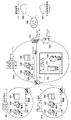
図1は、複数のネットワーク機器が設置された複数の顧客内ネットワークなどの拠点ネットワークと、それらネットワーク機器のための遠隔管理サービスサーバーとのネットワークの接続関係を示す図である。
[First Embodiment]
Hereinafter, embodiments for carrying out the present invention will be described with reference to the drawings.
<Configuration example of network device management system of this embodiment>
FIG. 1 is a diagram showing a network connection relationship between a base network such as a plurality of in-customer networks in which a plurality of network devices are installed and a remote management service server for those network devices.

図1において、100〜102は複写機などのネットワーク機器を示している。また、110〜112は顧客の社内LAN(ローカルエリアネットワーク)を示している。LAN110〜112のそれぞれのネットワークは拠点毎に分かれている。各拠点はWAN(ワイドエリアネットワーク)やインターネットVPN、広域イーサネット(登録商標)などのネットワークによって互いに接続されている。図1ではLAN110を顧客企業の本社内ネットワークとして示している。また、LAN111は本社とは別拠点にある営業所ネットワークを示しており、LAN112は、本社および営業所とは別拠点である工場内ネットワークを示している。ネットワーク機器100〜102は、顧客の社内LAN(Local Area Network)110〜112にそれぞれ接続された複合機(MFP(Multi-Function Printer))や単能機(SFP(Single Function Printer))などのプリンタ或いは画像形成装置を示している。 In FIG. 1, 100 to 102 indicate network devices such as copiers. In addition, 110 to 112 indicate the customer's internal LAN (local area network). Each network of LAN 110 to 112 is divided for each base. Each site is connected to each other by networks such as WAN (Wide Area Network), Internet VPN, and Wide Area Ethernet (registered trademark). Figure 1 shows LAN110 as the head office network of a client company. In addition, LAN111 indicates a sales office network located at a base separate from the head office, and LAN112 indicates an in-factory network located at a base separate from the head office and sales offices. Network devices 100-102 are printers such as multifunction devices (MFPs (Multi-Function Printers)) and single-function printers (SFPs (Single Function Printers)) that are connected to the customer's internal LAN (Local Area Network) 110 to 112, respectively. Alternatively, an image forming apparatus is shown.

本実施例では、ネットワークを介してさまざまな機器情報、稼働情報を送信可能な機能を備えるネットワーク機器100〜102として、プリント・スキャンなどの機能をもつ複写機を例示している。なお、本実施形態は、複写機以外にもそのような送信機能を備える機器であれば適用可能で、例えばプリンターやスキャナー、ネットワークカメラ、デジタル医療器などにも適用可能である。 In this embodiment, a copier having a function such as print / scan is illustrated as a network device 100-102 having a function capable of transmitting various device information and operation information via a network. In addition to the copying machine, the present embodiment can be applied to any device having such a transmitting function, and is also applicable to, for example, a printer, a scanner, a network camera, a digital medical device, and the like.

社内LANには、ネットワーク機器のほかに複数のPCや業務サーバー、その他の機器が接続されている。図1の本社内ネットワーク110にはさらに3つのネットワーク120,121,122が含まれている。ネットワーク120には一般の社員が利用する端末125やネットワーク機器100が接続されていることを示している。ネットワーク121は、顧客の社内LANとインターネット140との接続ポイントが設けられているネットワークであり、ファイアウォール132やプロクシ(Proxy)サーバー133が接続されていることを示している。ネットワーク122は顧客のデータセンターのネットワークを示しており、業務サーバー131やネットワーク機器100〜102を監視するための監視装置130が接続されている。ここでファイアウォール132はインターネット等の外部ネットワークと社内ネットワークとの通信を制限する機能を有する。 In addition to network devices, multiple PCs, business servers, and other devices are connected to the corporate LAN. The head office network 110 in FIG. 1 includes three additional networks 120,121,122. It shows that the terminal 125 and the network device 100 used by general employees are connected to the network 120. The network 121 is a network in which a connection point between the customer's corporate LAN and the Internet 140 is provided, and indicates that the firewall 132 and the proxy server 133 are connected. The network 122 shows the network of the customer's data center, and the monitoring device 130 for monitoring the business server 131 and the network equipment 100 to 102 is connected to the network 122. Here, the firewall 132 has a function of restricting communication between an external network such as the Internet and an internal network.

営業所内ネットワーク111には拠点LANであるネットワーク123があり、営業担当者などのユーザーが利用する端末126やネットワーク機器101が接続されている。工場内ネットワーク112には拠点LANであるネットワーク124があり、工場で働くユーザーが利用する端末127やネットワーク機器102が接続されている。また、インターネット140上には遠隔管理サービスサーバー150やその他情報提供サービス151などから構成される機器管理システムがあり、デバイスの稼働状況レポートや遠隔保守などのサービスを提供している。 The network 111 in the sales office has a network 123, which is a base LAN, to which terminals 126 and network devices 101 used by users such as sales staff are connected. The factory network 112 includes a network 124, which is a base LAN, to which terminals 127 and network devices 102 used by users working in the factory are connected. In addition, on the Internet 140, there is a device management system consisting of a remote management service server 150 and other information providing services 151, which provides services such as device operation status reports and remote maintenance.

図1に描いている顧客のネットワークは一例であり、インターネットには無数の企業LANが接続されている。企業ネットワーク110〜112には、セキュリティのためルーターやファイアウォールにアクセス制御が設定されている。例えば、工場内ネットワーク112のネットワークの端末からは本社ネットワーク110にあるデータセンターネットワーク122にアクセスが許可されている。この設定により工場内の端末127から業務サーバー131へアクセスし日々の業務を運営している。しかし、工場内の端末127からインターネット上のサービスにアクセスする必要がない場合、本社内ネットワーク121へのアクセス設定が行なわれていない。このような設定を施すことで工場内のネットワーク124に接続されている端末127からはインターネットへのアクセスができないようになっている。 The customer network depicted in Figure 1 is an example, and innumerable corporate LANs are connected to the Internet. Access control is set on routers and firewalls for security in corporate networks 110 to 112. For example, access is permitted to the data center network 122 in the head office network 110 from the network terminal of the factory network 112. With this setting, the terminal 127 in the factory accesses the business server 131 to operate daily business. However, when it is not necessary to access the service on the Internet from the terminal 127 in the factory, the access setting to the head office network 121 is not made. By making such a setting, the terminal 127 connected to the network 124 in the factory cannot access the Internet.

一方、本社や営業所では、業務上インターネット140へアクセスして外部から提供されるサービスを利用する必要がある。このような拠点のネットワーク120や123に接続されている端末125や126は、ネットワーク121へのアクセスが許されている。また、ネットワーク120や123に接続されている端末125や126は、データセンターネットワークに接続されている業務サーバー131にアクセスが許されている。 On the other hand, at the head office and sales offices, it is necessary to access the Internet 140 for business purposes and use services provided from the outside. Terminals 125 and 126 connected to networks 120 and 123 of such bases are allowed access to network 121. In addition, terminals 125 and 126 connected to networks 120 and 123 are allowed access to the business server 131 connected to the data center network.

このような環境で監視装置130は、顧客内ネットワークのどのネットワーク機器にもアクセスのできるデータセンターネットワーク122に接続されている。監視装置130は、インターネット上の遠隔管理サービスサーバー150へネットワーク機器の監視情報を送信するため、ネットワーク121へアクセスを許されている。またインターネット140へのアクセスが許されている場合には、ファイアウォール132の設定においても、ファイアウォール132を超えてインターネットへのアクセスが許されている。 In such an environment, the monitoring device 130 is connected to a data center network 122 that can access any network device in the customer's network. The monitoring device 130 is allowed to access the network 121 in order to transmit the monitoring information of the network device to the remote management service server 150 on the Internet. Further, when access to the Internet 140 is permitted, access to the Internet is permitted beyond the firewall 132 even in the setting of the firewall 132.

<本実施形態のネットワーク機器の制御部構成例>
図2は、図1におけるネットワーク機器100〜102等の監視装置130の監視対象となるネットワーク機器のハードウェア制御部の構成を示すブロック図である。ネットワーク機器100の制御部は主として、コピー、プリント、ブラウザーアプリケーションやネットワーク機器自身を監視する監視モジュールなどのプログラムの処理を行う。制御部は、システム管理を行う部分と、画像処理管理を行う部分から構成されている。
<Example of control unit configuration of network device of this embodiment>
FIG. 2 is a block diagram showing a configuration of a hardware control unit of a network device to be monitored by a monitoring device 130 such as the network device 100 to 102 in FIG. The control unit of the network device 100 mainly processes programs such as copy, print, browser application, and a monitoring module that monitors the network device itself. The control unit is composed of a part that performs system management and a part that performs image processing management.

システム管理を行う各構成要素は、操作部301、Network I/F部202、回線I/F部203、ROM204、RAM205、記憶装置206、CPU207から構成されている。また、画像処理管理を行う各構成要素は、IO制御部208、画像処理部209、画像回転部210、デジタルI/F部211、圧縮伸長部212、画素密度変換部213から構成されている。そして、これらの構成要素は、システムバス216及び画像バス217に接続されている。ROM204にはコピー、プリント、ネットワーク機器の監視プログラムなどの制御プログラムが格納される。 Each component that manages the system is composed of an operation unit 301, a network I / F unit 202, a line I / F unit 203, a ROM 204, a RAM 205, a storage device 206, and a CPU 207. Each component that manages image processing is composed of an IO control unit 208, an image processing unit 209, an image rotation unit 210, a digital I / F unit 211, a compression / expansion unit 212, and a pixel density conversion unit 213. Then, these components are connected to the system bus 216 and the image bus 217. The ROM 204 stores control programs such as copy, print, and network device monitoring programs.

記憶装置206にはウェブブラウザやユーザーによってインストールされたアプリケーションなどの一般的なプログラムが格納される。プログラムには、監視装置130の要求(リクエスト)に応じて装置自身の稼働状態や設定等を監視し、監視装置130に送信するなど、監視を実行する監視プログラム(あるいは監視モジュール)が含まれる。ROM204や記憶装置206に格納されたこれらのプログラムはCPU207で実行される。RAM205は、プログラムを実行するためのワークメモリエリアである。また、アプリケーションプログラムがネットワーク機器を制御するうえで必要な画像データやネットワークコンテンツを一時記憶するための画像メモリでもある。記憶装置206は不揮発性記憶装置であるため、ネットワーク機器100の再起動後も保持しておく必要のあるアプリケーションのライセンス情報や各設定値などが格納される。Network I/F202はLANと接続するためのインターフェース部であり、LANを介してネットワーク上のさまざまなコンピューターと通信を行う。 Storage 206 stores common programs such as web browsers and user-installed applications. The program includes a monitoring program (or monitoring module) that executes monitoring, such as monitoring the operating status and settings of the monitoring device 130 in response to a request (request) of the monitoring device 130 and transmitting it to the monitoring device 130. These programs stored in ROM 204 and storage 206 are executed by CPU 207. RAM205 is a work memory area for executing a program. It is also an image memory for temporarily storing image data and network contents necessary for an application program to control a network device. Since the storage device 206 is a non-volatile storage device, the license information of the application and each setting value that need to be retained even after the network device 100 is restarted are stored. Network I / F202 is an interface part for connecting to LAN, and communicates with various computers on the network via LAN.

また、ネットワーク機器に格納されているアプリケーションの起動や終了その他の処理は、ネットワーク機器外のプログラムからネットワークを介して指示することが可能である。例えば、ネットワーク機器自身を監視する監視モジュールは、監視装置130から指示を受けて起動したり、監視を開始したりすることができる。また、ネットワーク機器の各設定値についても同様であり、ネットワークを介して設定することができる。例えば、ネットワーク機器自身がインターネットアクセスをする際に利用するProxyサーバー133のアドレス設定は、監視装置130からの指示を受けて設定することができる。 In addition, the start and end of the application stored in the network device and other processes can be instructed from a program outside the network device via the network. For example, the monitoring module that monitors the network device itself can be activated or started by receiving an instruction from the monitoring device 130. The same applies to each setting value of the network device, which can be set via the network. For example, the address setting of the Proxy server 133 used when the network device itself accesses the Internet can be set by receiving an instruction from the monitoring device 130.

回線I/F部203は、公衆電話網に接続され、ROM204内の通信制御プログラムにより制御され、モデムなどの装置を介して遠隔の端末とデータの送受信を行う。ファクシミリの送受信もこの回線I/F部203を使用して行う。操作部201には表示手段やキー入力手段が内蔵されており、これらはCPU207にて制御される。操作者は、キー入力手段を通してスキャナー読み取りやプリント出力に関する各種設定指示や、作動/停止指示を行う。以上のデバイスがシステムバス216上に配置される。 The line I / F unit 203 is connected to the public telephone network, controlled by a communication control program in the ROM 204, and transmits / receives data to / from a remote terminal via a device such as a modem. Facsimile transmission and reception are also performed using this line I / F section 203. The operation unit 201 has a built-in display means and key input means, which are controlled by the CPU 207. The operator gives various setting instructions related to scanner reading and print output, and operation / stop instructions through the key input means. The above devices are placed on the system bus 216.

IO制御部208は、システムバス216と画像データを高速で転送する画像バス217とを接続するためのバスブリッジである。画像バス217は、たとえばPCIバスまたはIEEE1394で構成される。 The IO control unit 208 is a bus bridge for connecting the system bus 216 and the image bus 217 that transfers image data at high speed. The image bus 217 is composed of, for example, a PCI bus or IEEE1394.

画像バス217上には以下のデバイスが配置される。デジタルI/F部211は、デバイスのリーダー部215やプリンター部214と制御部とを接続し、画像データの同期系/非同期系の変換を行う。また、リーダー部215やプリンター部214内の各所に配置した前述の各種センサーが検出した情報は、このデジタルI/F部211、及びIO制御部208を介してシステムバス216へ流れる。 The following devices are arranged on the image bus 217. The digital I / F unit 211 connects the device reader unit 215 or printer unit 214 to the control unit, and performs synchronous / asynchronous conversion of image data. In addition, the information detected by the various sensors arranged in the reader section 215 and the printer section 214 flows to the system bus 216 via the digital I / F section 211 and the IO control section 208.

画像処理部209は、入力及び出力画像データに対し補正/加工/編集を行う。画像回転部210は画像データの回転を行う。画像圧縮伸長部212は、多値画像データはJPEG、2値画像データはJBIG/MMR/MR/MHの圧縮伸張処理を行う。画像密度変換部213は、出力用画像データに対して解像度変換等を行う。 The image processing unit 209 corrects / processes / edits the input and output image data. The image rotation unit 210 rotates the image data. The image compression / expansion unit 212 performs compression / expansion processing of JPEG for multi-valued image data and JBIG / MMR / MR / MH for binary image data. The image density conversion unit 213 performs resolution conversion or the like on the output image data.

上記構成により、ネットワーク機器101〜103は、複写機やプリンター、スキャナー等の機能を提供すると共に、ネットワークを介してデータセンターネットワーク122に設けられた監視装置130と通信することができる。また、監視モジュールを実行することができる。 With the above configuration, the network devices 101 to 103 can provide functions such as a copier, a printer, and a scanner, and can communicate with the monitoring device 130 provided in the data center network 122 via the network. You can also run the monitoring module.

<ネットワーク機器のソフトウェアモジュール構成>
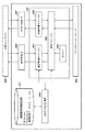
図3は、図1における監視装置130の監視対象となるネットワーク機器100〜103のソフトウェアモジュールの構成、特に監視モジュールに関する構成を説明する図である。図中の301乃至307、及び、309乃至311がネットワーク機器100のソフトウェアモジュールに該当する。301はネットワーク機器における自己監視モジュールを表しており、その中で中心的な処理を行なう302は全体マネージャーを表している。図中308はネットワーク機器外部のネットワークを表しており、図1ではLAN120、123、124に相当する。そこに外部からの指示を受けつけ、ネットワーク機器の管理情報を提供するIFとして設定管理IF305がある。この設定管理IF305は外部からのリクエストに対して、ネットワーク機器内で処理を実行し、要求されたデータを返し、さらにネットワーク機器内の設定情報を変更するためのIFを提供している。例えば、プロトコルとしてSNMPのようなネットワーク機器を管理するためのプロトコルを用いることができるが、ここではSNMPに限定することはなく、その他の標準プロトコル、独自のプロトコル、及び、その他の管理プロトコルなどを利用してもよい。
<Software module configuration of network equipment>
FIG. 3 is a diagram illustrating a configuration of software modules of network devices 100 to 103 to be monitored by the monitoring device 130 in FIG. 1, particularly a configuration related to the monitoring module. 301 to 307 and 309 to 311 in the figure correspond to the software module of the network device 100. 301 represents the self-monitoring module in the network equipment, and 302, which performs the central processing in it, represents the overall manager. In the figure, 308 represents a network outside the network device, and in FIG. 1, it corresponds to LANs 120, 123, and 124. There is a setting management IF305 as an IF that receives instructions from the outside and provides management information of network devices. This setting management IF305 provides an IF for executing processing in the network device, returning the requested data, and changing the setting information in the network device in response to an external request. For example, a protocol for managing network devices such as SNMP can be used as a protocol, but the protocol is not limited to SNMP here, and other standard protocols, proprietary protocols, and other management protocols may be used. You may use it.

303はタイマーを表している。監視モジュール301の全体マネージャー302が常にネットワーク機器の状態を監視している。ネットワーク機器にジャムやエラーなどのイベントが発生するとデバイスインターフェース309を介してイベントに係るイベント情報を収集して、遠隔管理サービスサーバー150へ収集したイベント情報を送信する。 303 represents a timer. The general manager 302 of the monitoring module 301 constantly monitors the status of network devices. When an event such as a jam or an error occurs in the network device, the event information related to the event is collected via the device interface 309, and the collected event information is transmitted to the remote management service server 150.

その他に、カウンターやログなどの情報は送信タイミングをタイマー303にセットしておき、遠隔管理サービスサーバー150に送信すべき時刻になったらタイマー303から呼び出しを受ける。そしてあらかじめ決められたデータを決められた所定の時間間隔で遠隔管理サービスサーバー150に送信する。 In addition, the transmission timing of information such as counters and logs is set in the timer 303, and when the time to be transmitted to the remote management service server 150 comes, the timer 303 calls. Then, the predetermined data is transmitted to the remote management service server 150 at a predetermined predetermined time interval.

304は自己監視モジュールにおける設定管理マネージャーを表している。ここではネットワークを介して設定される系のみを記載しているが、LUI(ローカルUI)など別のIFからの指示に対してもまとめて設定情報の管理を行なってもよい。例えば、遠隔管理サービスサーバー150のURL設定やProxyサーバーの設定、自己監視の開始/停止、などの設定を外部から受け付け、全体マネージャー302と連携して制御している。これらの設定変更は、ローカルUIからでも可能である。 304 represents the configuration management manager in the self-monitoring module. Although only the system set via the network is described here, the setting information may be managed collectively for the instruction from another IF such as LUI (local UI). For example, the URL setting of the remote management service server 150, the proxy server setting, the start / stop of self-monitoring, and other settings are accepted from the outside and controlled in cooperation with the overall manager 302. These settings can also be changed from the local UI.

306は通信管理マネージャーを表している。全体マネージャー302はイベントの発生やタイマー303の満了に応じてネットワーク機器の監視情報を遠隔管理サービスサーバー150に送信する。このときこの通信管理マネージャー306によって送信すべき必須データがこのモジュールが収集し、送信すべきデータが十分であるか否かを確認して送信を行なう。また、通信管理マネージャー306は、情報の優先順位や再送すべきか否かなどの制御をして適切な順番と適切なタイミングで送信制御を行なう。 306 represents the communication management manager. The general manager 302 sends the monitoring information of the network device to the remote management service server 150 in response to the occurrence of an event or the expiration of the timer 303. At this time, the communication management manager 306 collects the essential data to be transmitted by this module, confirms whether or not the data to be transmitted is sufficient, and then transmits the data. In addition, the communication management manager 306 controls the priority of information and whether or not the information should be retransmitted, and performs transmission control in an appropriate order and at an appropriate timing.

307はHTTP/SOAP IFを表している。このIFはHTTPクライアントであり、外部ネットワーク308に対してデータを送信するためのIFである。ここでは遠隔管理サービスサーバー150に対してネットワーク機器の自己監視情報を送信するためのクライアントとなっている。ここでSOAP(Single Object Access Protocol)は、XMLベースのプロトコルであり、たとえばWebサービスの提供や利用のために用いられる。すなわち本例ではSOAPを用いて監視サーバー150との間でメッセージの送受信を行う。なお図中には、HTTP/SOAPとプロトコルの記載をしているが、REST/JSONを用いた軽量プロトコルでも、MQTTやWeb Socketを用いたIOTなどに利用が見込まれているプロトコルを利用してもよい。ここはネットワーク機器の監視情報を遠隔管理サービスサーバー150に送信するための処理を行なうモジュールでありプロトコルを限定しない。 307 represents HTTP / SOAP IF. This IF is an HTTP client and is an IF for sending data to the external network 308. Here, it is a client for transmitting self-monitoring information of network devices to the remote management service server 150. Here, SOAP (Single Object Access Protocol) is an XML-based protocol, and is used for providing and using Web services, for example. That is, in this example, SOAP is used to send and receive messages to and from the monitoring server 150. Although HTTP / SOAP and protocols are described in the figure, even lightweight protocols using REST / JSON use protocols that are expected to be used for IOT using MQTT and Web Socket. May be good. This is a module that performs processing for transmitting monitoring information of network devices to the remote management service server 150, and does not limit the protocol.

310は機器設定情報格納部に対するDBアクセスを管理するDBアクセス管理部を表している。また311は、機器設定情報格納部であり、機器の設定情報を格納しておくためのDBを表している。機器設定情報格納部311では、主にIPアドレスやProxyサーバーなどのネットワーク系設定情報や遠隔管理サービスサーバー150のURL情報などが格納されている。機器設定情報格納部311にはこのほか、たとえばイベントの発生のつど収集される情報等を格納してもよい。例えば、図1では監視装置130がネットワーク機器に対して、Proxyサーバーの設定と遠隔管理サービスサーバー150に対する通信テストとを指示した場合には、ネットワーク機器、特に設定管理マネージャー304は、設定管理IF305を介して設定変更等の指示を受け付ける。プロクシサーバーの設定とは、ここではネットワーク機器がプロクシサーバーを介して通信を行うための、ネットワーク機器に対する設定である。設定管理マネージャー304は、Proxyサーバーの設定指示を受け付けるとDBアクセス管理部301を介してDBすなわち機器設定情報格納部311にProxyサーバーの設定を格納する。またこの処理と共に全体マネージャー302に通信テスト発行指示が発行される。 310 represents a DB access management unit that manages DB access to the device setting information storage unit. Further, 311 is a device setting information storage unit, and represents a DB for storing device setting information. The device setting information storage unit 311 mainly stores network setting information such as an IP address and Proxy server, and URL information of the remote management service server 150. In addition, the device setting information storage unit 311 may store, for example, information to be collected each time an event occurs. For example, in FIG. 1, when the monitoring device 130 instructs the network device to set the Proxy server and the communication test for the remote management service server 150, the network device, especially the setting management manager 304, sets the setting management IF305. Accepts instructions such as setting changes via. The proxy server setting here is a setting for the network device for the network device to communicate via the proxy server. When the setting management manager 304 receives the setting instruction of the Proxy server, the setting management manager 304 stores the setting of the Proxy server in the DB, that is, the device setting information storage unit 311 via the DB access management unit 301. Along with this process, a communication test issuance instruction is issued to the overall manager 302.

この通信テスト発行指示により、全体マネージャー302はDBアクセス管理部310を介して、通信テストに必要な情報を取得する。この必要な情報とは、遠隔管理サービスサーバー150のURLや、設定したProxyサーバー133のアドレスである。この情報を取得した全体マネージャー302は、通信テストを実行するために通信管理マネージャー306に取得した情報とともに通信テスト指示を発行する。通信マネージャー306は、通信テストの相手のURLやProxyサーバー133のアドレスのほかに、ネットワーク機器の識別子やその他通信テストを実行するために必要な情報を収集し、HTTP/SOAP IF307に通信テスト指示を与える。するとHTTP/SOAP IF307は遠隔管理サービスサーバー150に対して通信テストを実施し、テスト成功のレスポンスを受けると共に全体マネージャー302はネットワーク機器の自己監視を開始する。 By this communication test issuance instruction, the general manager 302 acquires the information necessary for the communication test via the DB access management unit 310. This necessary information is the URL of the remote management service server 150 and the address of the proxy server 133 that has been set. The general manager 302 that has acquired this information issues a communication test instruction together with the acquired information to the communication management manager 306 in order to execute the communication test. The communication manager 306 collects the URL of the communication test partner and the address of the Proxy server 133, as well as the identifier of the network device and other information necessary to execute the communication test, and issues a communication test instruction to HTTP / SOAP IF 307. give. Then, HTTP / SOAP IF307 conducts a communication test on the remote management service server 150, receives a response of the test success, and the overall manager 302 starts self-monitoring of the network device.

<本実施形態の監視装置130の制御部構成例>
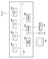
図4は、図1における監視装置130、遠隔管理サービスサーバー150を実現するためのサーバーPCなどの情報処理装置のハードウェア構成を示すブロック図である。監視装置130では、ネットワークを介してネットワーク機器100〜102からバイスの管理情報を収集するためのアプリケーションが実行される。また、監視装置130は、一般的な情報処理装置の構成を備えている。すなわち、バス401、CPU402、ROM403、RAM404に加えて、LAN等のネットワークへ接続するためのNetwork I/F405、表示デバイス409を制御する表示制御部406、入力デバイス410、411を制御する入力制御部407、記憶装置408を備えている。
<Example of Control Unit Configuration of Monitoring Device 130 of the Present Embodiment>
FIG. 4 is a block diagram showing a hardware configuration of an information processing device such as a server PC for realizing the monitoring device 130 and the remote management service server 150 in FIG. The monitoring device 130 executes an application for collecting vise management information from network devices 100 to 102 via a network. Further, the monitoring device 130 has a configuration of a general information processing device. That is, in addition to the bus 401, CPU402, ROM403, and RAM404, the Network I / F405 for connecting to a network such as a LAN, the display control unit 406 that controls the display device 409, and the input control unit that controls the input devices 410 and 411. It is equipped with 407 and storage device 408.

バス401は、図1の監視装置130を構成する各構成部品間のデータを受け渡す共通信号路である。RAM404は、書換え可能な記憶手段であり、ネットワーク機器の管理ソフトウェアを実行するためのワークメモリエリアとなる。ネットワーク機器の管理ソフトウェアには、ネットワークを介してネットワーク機器から監視情報を取得するプログラムや設定変更指示を発行するプログラム、処理の開始や停止を指示するプログラムなどがある。ネットワーク機器から取得した監視情報はこのRAM404で展開され所定の形にデータ変換される。 The bus 401 is a common signal path for passing data between the components constituting the monitoring device 130 of FIG. 1. The RAM404 is a rewritable storage means, and serves as a work memory area for executing management software for network devices. Network device management software includes a program that acquires monitoring information from a network device via a network, a program that issues a setting change instruction, and a program that instructs the start and stop of processing. The monitoring information acquired from the network device is expanded by this RAM 404 and converted into data in a predetermined form.

記憶装置408は、不揮発性記憶装置である。記憶装置408には、監視装置130のハードウェア制御を行うOSが記憶されている。また、このほかに管理対象となる複数ネットワーク機器のリストや、管理ソフトウェアやプラグインソフトウェアを構成する各プログラムが記憶されている。記憶装置408には、これらのプログラムのほかにプログラムの処理に利用するための設定情報、例えば、ネットワーク機器へリクエスト発行するための認証情報やSNMPのコミュニティネームもこの不揮発性記憶装置408に格納される。 The storage device 408 is a non-volatile storage device. The storage device 408 stores the OS that controls the hardware of the monitoring device 130. In addition, a list of multiple network devices to be managed and each program constituting the management software and the plug-in software are stored. In addition to these programs, the storage device 408 also stores setting information used for program processing, for example, authentication information for issuing a request to a network device and an SNMP community name in the non-volatile storage device 408. To.

Network I/F405は、監視装置130がネットワークへ接続するためのインターフェースであり、監視装置130はネットワークを介してネットワーク機器と通信を行う。 The Network I / F405 is an interface for the monitoring device 130 to connect to the network, and the monitoring device 130 communicates with the network device via the network.

CPU402は、各構成部品403〜411を個別に又は統合的に制御するものであり、記憶装置408に格納されたプログラム基づき、Network I/F405を介してネットワーク機器の監視情報を収集したり制御したりする。 The CPU 402 controls each component 403 to 411 individually or in an integrated manner, and collects and controls monitoring information of network devices via the Network I / F 405 based on a program stored in the storage device 408. Or something.

<監視装置130のソフトウェアモジュール構成>
監視装置130は、顧客のネットワーク内に設置され顧客のネットワークに接続されている複数のネットワーク機器を監視する。図5は、監視装置130上で実行される監視装置ソフトウェアにおけるネットワーク機器への指示発行処理を行なうプログラムの機能を示すブロック図である。SFP(シングルファンクションプリンタ)などシンプルな機能を有するネットワーク機器に対して、監視装置130はネットワークを介してステータス情報を要求する。そして得られた監視情報から遠隔管理サービスサーバー150に対して監視情報を送信するか否かの判断を行なう。一方、MFP(マルチファンクションプリンタ)のようにスキャンやプリント、FAXなど複数の機能を有しているネットワーク機器は自身を監視するためのプログラムである監視モジュールが提供され、インストールできる場合がある。このような監視モジュールがインストールされたネットワーク機器に対して監視装置130は、Proxyサーバー133の設定やネットワーク機器内の監視プログラムの起動をネットワーク越しに指示する。監視モジュールを持たないデバイスは、監視装置130からの要求に応じたステータス情報を返すため、一般的な項目が監視の対象となることが多い。これに対して監視モジュールは、それがインストールされているデバイスのために開発されているので、監視モジュールを持つデバイスは、たとえば固有の機能に係る情報など、より詳細な情報を収集し、監視装置130に提供することができる。
<Software module configuration of monitoring device 130>
The monitoring device 130 monitors a plurality of network devices installed in the customer's network and connected to the customer's network. FIG. 5 is a block diagram showing a function of a program for issuing instructions to network devices in the monitoring device software executed on the monitoring device 130. The monitoring device 130 requests status information via a network from a network device having a simple function such as an SFP (single function printer). Then, it is determined whether or not to transmit the monitoring information to the remote management service server 150 from the obtained monitoring information. On the other hand, network devices that have multiple functions such as scanning, printing, and faxing, such as MFPs (multifunction printers), may be provided with a monitoring module, which is a program for monitoring themselves, and can be installed. The monitoring device 130 instructs the network device in which such a monitoring module is installed to set the Proxy server 133 and start the monitoring program in the network device over the network. Since a device that does not have a monitoring module returns status information in response to a request from the monitoring device 130, general items are often monitored. Monitoring modules, on the other hand, are developed for the devices on which they are installed, so devices with monitoring modules collect more detailed information, such as information about unique functions, and monitoring devices. Can be provided to 130.

図5では、監視装置130のソフトウェアを構成する各ソフトウェアモジュールの入出力処理の例について説明する。ネットワーク機器のメンテナンスサービスを顧客に提供する担当者をユーザーAとして表している。監視装置ソフトウェアは、ユーザーAから管理対象となるネットワーク機器の登録を受け付けるためのUIを有する。 FIG. 5 describes an example of input / output processing of each software module constituting the software of the monitoring device 130. User A represents the person in charge of providing maintenance services for network equipment to customers. The monitoring device software has a UI for accepting registration of network devices to be managed from user A.

ユーザーIF(UI)制御部501が、遠隔監視装置ソフトウェアにおけるデバイス登録用画面を提供する。ユーザーAは、監視を行なう対象のネットワーク機器リストをネットワークから探索したり顧客に販売したネットワーク機器のリストから作成したりすることで準備する。そして、そのネットワーク機器リストをUI制御部501から監視情報格納部504に登録を行なう。このネットワーク機器リストには、ネットワーク機器のシリアル番号やIPアドレスなどネットワークのアドレス情報が含まれている。これにより監視装置130は顧客内ネットワークでネットワーク機器にアクセスすることができるようになる。また、ユーザーIF入出力制御部では登録されたネットワーク機器リストを表示し、ユーザーAの指示に従いネットワーク機器を監視対象とするか否かを制御することができる。 The user IF (UI) control unit 501 provides a device registration screen in the remote monitoring device software. User A prepares by searching the network for a list of network devices to be monitored or creating a list of network devices sold to customers. Then, the network device list is registered from the UI control unit 501 to the monitoring information storage unit 504. This network device list includes network address information such as the serial number and IP address of the network device. As a result, the monitoring device 130 can access the network device in the customer's in-customer network. In addition, the user IF input / output control unit can display the registered network device list and control whether or not the network device is to be monitored according to the instruction of user A.

例えば、監視対象の複数のネットワーク機器に対して、通信テストを実行というボタンを表示し監視開始の指示を受け付ける。そのほかに特定のネットワーク機器を監視対象からはずす指示をユーザーAから受け付ける。502は、監視装置ソフトウェアの中心的な処理を行なう全体管理マネージャーを表している。全体管理マネージャー502は、監視装置ソフトウェア内の各モジュールに対して処理指示を発行したり、指示を伝達したりして、一連の処理が正しく実行されるように管理を行なう。 For example, a button for executing a communication test is displayed for a plurality of network devices to be monitored, and an instruction to start monitoring is received. In addition, user A accepts an instruction to remove a specific network device from the monitoring target. Reference numeral 502 is a general management manager that performs the central processing of the monitoring device software. The general management manager 502 issues processing instructions to each module in the monitoring device software and transmits the instructions to manage the series of processes so that they are executed correctly.

503は、監視装置ソフトウェアの情報格納部に対する入出力部を示している。504は、監視装置ソフトウェアの監視情報格納部を示している。監視情報格納部504は、ユーザーAからまたはその他の登録方法により登録された監視対象候補および、監視対象のネットワーク機器リストを記憶装置408に格納する。また、この監視情報格納部504は、すべてのネットワーク機器のネットワークアドレスや、製品名、識別子などの監視情報を記憶装置408に格納して管理する。そのほか、監視情報格納部504には、監視対象のネットワーク機器の各ネットワーク機器の性能や機能、さらに監視情報の収集方法や監視に必要なすべての情報も記憶装置408に格納し、管理する。 Reference numeral 503 is an input / output unit for the information storage unit of the monitoring device software. Reference numeral 504 indicates a monitoring information storage unit of the monitoring device software. The monitoring information storage unit 504 stores the monitoring target candidate registered from the user A or by another registration method and the network device list of the monitoring target in the storage device 408. Further, the monitoring information storage unit 504 stores and manages monitoring information such as network addresses, product names, and identifiers of all network devices in the storage device 408. In addition, the monitoring information storage unit 504 stores and manages the performance and functions of each network device of the network device to be monitored, as well as the method of collecting monitoring information and all the information necessary for monitoring in the storage device 408.

505は、Proxyプロセス制御部を示している。監視装置ソフトウェアは、監視装置130自身が必要であると判断した場合、または、ユーザーAから指示された場合、Proxyサーバーとしての機能を有効化することができる。すなわち監視装置130をプロクシサーバーとして機能させることができる。506は、遠隔管理サーバー150から発行された指示コマンドのステータス管理部を示している。監視装置130は、遠隔管理サービスサーバー150からネットワークを介して指示コマンドの取得を行なう。この指示コマンドの取得は、監視装置130が遠隔管理サービスサーバー150に対して指示コマンドの問い合わせメソッドを送信して、ポーリングをすることで処理を取得してもよい。これは、ファイアウォール132が外部からの自発的なリクエストをブロックするため、遠隔管理サービスサーバー150が自発的に指示コマンドを送信しても、ファイアウォール132を超えられない可能性があるためである。そのほか、MQTTやWeb SocketのようなHTTP/HTTPSなどのプロトコル上でTCPレベルのセッションを維持してリアルタイムに遠隔管理サービスサーバー150から指示コマンドを受信してもよい。監視装置130は、遠隔管理サービスサーバー150から指示コマンドを受信すると、その指示コマンドを実行し処理結果がどのような結果となったか、各処理のフェーズでステータスを管理する。 Reference numeral 505 indicates a Proxy process control unit. The monitoring device software can enable the function as a Proxy server when the monitoring device 130 itself determines that it is necessary or when instructed by user A. That is, the monitoring device 130 can function as a proxy server. Reference numeral 506 is a status management unit of the instruction command issued from the remote management server 150. The monitoring device 130 acquires instruction commands from the remote management service server 150 via the network. The acquisition of this instruction command may be acquired by the monitoring device 130 sending the inquiry method of the instruction command to the remote management service server 150 and polling. This is because the firewall 132 blocks voluntary requests from the outside, so even if the remote management service server 150 voluntarily sends an instruction command, the firewall 132 may not be exceeded. In addition, a TCP-level session may be maintained on a protocol such as HTTP / HTTPS such as MQTT or Web Socket to receive instruction commands from the remote management service server 150 in real time. When the monitoring device 130 receives the instruction command from the remote management service server 150, the monitoring device 130 executes the instruction command and manages the status of the processing result in each processing phase.

ステータス管理部506は、最終的に受信した指示コマンドに対する処理結果を管理し、その結果を遠隔管理サービスサーバー150へ送信するまでの管理を行なっている。 The status management unit 506 manages the processing result for the finally received instruction command, and manages the result until it is transmitted to the remote management service server 150.

監視装置130は、遠隔管理サービスサーバー150から指示コマンドを受信する。受信される指示コマンドは通常、監視装置130宛ての指示コマンドであるが、特定のネットワーク機器宛の指示コマンドを受けることもある。このようなケースの場合、一旦監視装置130は特定のネットワーク機器宛の指示コマンドを受け付けて、改めて対象のネットワーク機器に対してネットワークを介して指示を発行する。 The monitoring device 130 receives an instruction command from the remote management service server 150. The instruction command received is usually an instruction command addressed to the monitoring device 130, but it may also receive an instruction command addressed to a specific network device. In such a case, the monitoring device 130 once receives an instruction command addressed to a specific network device, and issues an instruction to the target network device again via the network.

507は、機器通信管理部を示している。機器通信管理部507では、監視装置130の監視情報格納部504に格納されているネットワーク機器リストのネットワークアドレスをベースにネットワーク機器と通信を行なう。この通信ではネットワーク機器の存在確認や、ネットワーク機器の識別、ネットワーク機器の種別判別、能力確認(ファームウェアバージョンの確認や、特定モジュールの応答)などを行なう。また、SNMPや独自プロトコルを利用してネットワーク機器の障害情報やプリンターの利用状況などのネットワーク機器監視情報を取得する。その他、監視モジュールが組み込まれているネットワーク機器については、ポーリング形式での監視となり効率が良くない。この監視モジュールは組み込みのモジュールと記載しているが、ネットワーク機器上で処理が動くプログラムであればよく、形態には制限しない。具体的には、インストールする形態のプログラムでも、オプション機器を取り付けるネットワーク機器上で動くプログラムでもよい。 Reference numeral 507 indicates a device communication management unit. The device communication management unit 507 communicates with the network device based on the network address of the network device list stored in the monitoring information storage unit 504 of the monitoring device 130. In this communication, the existence of the network device is confirmed, the network device is identified, the type of the network device is determined, and the capability is confirmed (firmware version confirmation, response of a specific module), and the like. In addition, network device monitoring information such as network device failure information and printer usage status is acquired using SNMP and proprietary protocols. In addition, network equipment with a built-in monitoring module is monitored in a polling format, which is not efficient. Although this monitoring module is described as a built-in module, it is not limited to any form as long as it is a program that operates on a network device. Specifically, it may be a program in the form of installation or a program running on a network device to which an optional device is attached.

このようなケースでは、全体管理マネージャー502はネットワーク機器自身に組み込まれている監視モジュールを有効化するための指示を発行する。そのまま監視モジュールを有効しても遠隔管理サービスサーバー150との通信ができるようなるとは限らない。たとえばネットワーク機器による通信が、ファイアウォール132を超えてインターネット140へアクセスできないように設定されている場合がある。そこで、監視装置130はネットワーク機器がインターネット140へアクセスできるようにProxyサーバー133のアドレスを設定指示し、Proxyサーバー133を介してインターネット140へアクセスさせることが考えられる。 In such a case, the overall management manager 502 issues an instruction to activate the monitoring module built into the network device itself. Even if the monitoring module is enabled as it is, it is not always possible to communicate with the remote management service server 150. For example, communication by a network device may be set so that it cannot access the Internet 140 beyond the firewall 132. Therefore, it is conceivable that the monitoring device 130 sets and instructs the address of the Proxy server 133 so that the network device can access the Internet 140, and accesses the Internet 140 via the Proxy server 133.

しかし、ネットワーク機器の設置されているネットワークからProxyサーバー133のアドレスを設定するだけで直接インターネットに接続できないことがおおい。そこで、監視装置130がネットワーク機器の監視モジュールを起動させるような場合、監視装置130内でProxyのプロセスを起動し、監視装置130にProxyサーバー機能を持たせる。全体管理マネージャー502は監視装置130のProxyのプロセスがすでに起動済みか否かを判定し、Proxyのプロセスが起動していない場合、Proxyプロセス制御部505にProxy機能の指示を発行する。そして監視装置130自身にProxyのプロセスが立ち上がると、ネットワーク機器に自己監視プログラムすなわち監視モジュールを有効にするよう指示するタイミングで、Proxyサーバーのアドレスとして監視装置130のネットワークアドレスをネットワーク機器に登録する。 However, it is often not possible to connect directly to the Internet simply by setting the address of Proxy server 133 from the network where the network equipment is installed. Therefore, when the monitoring device 130 starts the monitoring module of the network device, the Proxy process is started in the monitoring device 130, and the monitoring device 130 is provided with the Proxy server function. The general management manager 502 determines whether the Proxy process of the monitoring device 130 has already started, and if the Proxy process has not started, issues a Proxy function instruction to the Proxy process control unit 505. Then, when the Proxy process is started up in the monitoring device 130 itself, the network address of the monitoring device 130 is registered in the network device as the proxy server address at the timing of instructing the network device to enable the self-monitoring program, that is, the monitoring module.

<遠隔管理サービスサーバー150のソフトウェアモジュール構成>
遠隔管理サービスサーバー150は、インターネット上に存在するさまざまなサービスのうちの1つである。このサービスは、顧客環境に設置したネットワーク機器の監視情報を収集し、サービスマンやメンテナンス契約会社にメンテナンスのためのサポート情報を提供する。
<Software module configuration of remote management service server 150>
The remote management service server 150 is one of various services existing on the Internet. This service collects monitoring information of network equipment installed in the customer environment and provides support information for maintenance to service personnel and maintenance contract companies.

図6は、遠隔管理サービスサーバー150上で実行される遠隔管理サービスサーバーソフトウェアにおけるネットワーク機器への指示コマンド発行処理を行なうプログラムの機能を示すブロック図である。図6では、遠隔管理サービスサーバー150のソフトウェアを構成する各ソフトウェアモジュールの入出力処理の例について説明する。遠隔管理サービスサーバー150を利用して収集されたネットワーク機器の監視情報を利用する担当者をユーザーBとして表している。また、遠隔管理サービスサーバー150は、指示コマンドをユーザーBから受け付け特定のネットワーク機器に対して送信し、遠隔のネットワーク機器に対して処理を実行させることができる。 FIG. 6 is a block diagram showing a function of a program that issues an instruction command to a network device in the remote management service server software executed on the remote management service server 150. FIG. 6 describes an example of input / output processing of each software module constituting the software of the remote management service server 150. The person in charge of using the monitoring information of the network device collected by using the remote management service server 150 is represented as user B. Further, the remote management service server 150 can receive an instruction command from the user B, transmit it to a specific network device, and cause the remote network device to execute the process.

ここではユーザーBが指示コマンド発行時の処理について説明する。ネットワーク機器の管理形態として、顧客ネットワーク内に監視装置130が設置されている場合には、監視装置130を介して特定のネットワーク機器に対して指示コマンドを発行する。ユーザーBは、遠隔管理サービスサーバー150を介して任意のネットワーク機器に対して処理コマンドを処理させたい場合、監視装置130に対象のネットワーク機器宛てに指示コマンドを発行する。 Here, the processing when user B issues an instruction command will be described. As a management form of the network device, when the monitoring device 130 is installed in the customer network, an instruction command is issued to a specific network device via the monitoring device 130. When the user B wants an arbitrary network device to process a processing command via the remote management service server 150, the user B issues an instruction command to the target network device to the monitoring device 130.

また、監視装置130が顧客ネットワーク上になく、ネットワーク機器上で監視モジュールが動いている場合、指示コマンドの問い合わせ通信は、各ネットワーク機器が発行する。このため、ユーザーBが対象のネットワーク機器に指示コマンドを発行すると、対象のネットワーク機器が指示コマンドの問い合わせの通信を行った際にその応答に指示コマンドを発行する。 Further, when the monitoring device 130 is not on the customer network and the monitoring module is operating on the network device, the inquiry communication of the instruction command is issued by each network device. Therefore, when the user B issues an instruction command to the target network device, the instruction command is issued to the response when the target network device communicates the inquiry of the instruction command.

601はインターネットに公開しているWeb Serviceのインターフェースである。このインターフェースを介してネットワーク機器からの監視情報を受信したり指示コマンドの問い合わせに対して、指示を発行したりする。 601 is a Web Service interface that is open to the Internet. Through this interface, it receives monitoring information from network devices and issues instructions in response to inquiries about instruction commands.

602はネットワーク機器から送信された監視情報をWebService601が受信した後、データの種類やどのようなデータを受信したのかを解釈する解釈部である。たとえばSOAPを用いていれば、解釈部602はSOAPメッセージを解釈する。 Reference numeral 602 is an interpretation unit that interprets the type of data and what kind of data is received after WebService601 receives the monitoring information transmitted from the network device. For example, if SOAP is used, the interpreter 602 interprets the SOAP message.

603は、応答作成部であり、たとえばネットワーク機器から受信した監視情報に対して、データ受信を受け付けたことを示すOK応答や、指示コマンドの問い合わせに対して、応答時に指示を発行したりする。 Reference numeral 603 is a response creation unit, which issues an instruction at the time of responding to an OK response indicating that data reception has been accepted for monitoring information received from a network device or an inquiry of an instruction command.

604は全体管理マネージャーであり、ユーザーからの入力やネットワーク機器からの監視情報の受信について一連の処理を各モジュールに発行し指示する管理プログラムである。 604 is an overall management manager, which is a management program that issues and instructs each module to perform a series of processes regarding input from users and reception of monitoring information from network devices.

605は管理情報入出力部であり、ユーザーからのリクエストに応じて条件に合致するネットワーク機器を特定したり、ユーザーが特定ネットワーク機器に発行した指示コマンドのステータスについてDBに書き込んだり、読み出したりする。 Reference numeral 605 is a management information input / output unit, which identifies a network device that meets the conditions in response to a request from the user, and writes or reads the status of an instruction command issued by the user to the specific network device in the DB.

606は、管理情報格納部であり、遠隔管理サービスサーバー150にて管理されているすべてのネットワーク機器情報や、管理情報などが格納されている。また、ユーザーの発行した指示コマンドのステータスや処理結果などが格納されている。 Reference numeral 606 is a management information storage unit, which stores all network device information and management information managed by the remote management service server 150. In addition, the status and processing results of instruction commands issued by the user are stored.

また、遠隔管理サービスサーバーソフトウェアは、ユーザーBから特定ネットワーク機器に発行する指示コマンドを受け付けるためのUIを有する。遠隔管理サービスサーバーソフトウェアにおける指示コマンドを受け付ける画面をユーザーIF(UI)制御部607とする。例えば、特定ネットワーク機器への指示を発行する際には、以下のような処理が遠隔管理サービスサーバー150にて実行される。ユーザーBは、管理対象のネットワーク機器リストから指示発行対象のネットワーク機器を検索する。このときには、UI制御部607で受信したネットワーク機器を検索するためのクエリは全体管理マネージャー604を介して管理情報入出力部605に送信される。対象ネットワーク機器を特定するためのクエリを受けた管理情報入出力部605は、管理情報格納部606から条件に合致したネットワーク機器を特定し応答として返す。UI制御部607を介してユーザーBに対してクエリ結果となるネットワーク機器情報が提示(たとえば表示)される。ユーザーBは、そのネットワーク機器が目的のネットワーク機器であった場合には、発行可能な指示リストを画面UIから選択し、その指示の発行を設定する。UI制御部607を介してこの指示を受信した全体管理マネージャー604は、管理情報入出力部605を介してネットワーク機器の監視構成を取得する。監視構成とは例えば、ネットワーク機器が監視装置による監視の対象であるか否かや、あるいは監視モジュールがインストールされているか否か、インストールされている監視モジュールの提供する機能などを示す情報であってよい。監視構成を参照することで、たとえば、ネットワーク機器が、監視モジュールを有し、かつ監視装置130による監視対象であることを知ることができる。 In addition, the remote management service server software has a UI for receiving an instruction command issued from user B to a specific network device. The screen for receiving instruction commands in the remote management service server software is referred to as the user IF (UI) control unit 607. For example, when issuing an instruction to a specific network device, the following processing is executed by the remote management service server 150. User B searches for the network device for which the instruction is issued from the list of managed network devices. At this time, the query for searching the network device received by the UI control unit 607 is sent to the management information input / output unit 605 via the general management manager 604. Upon receiving the query for identifying the target network device, the management information input / output unit 605 identifies the network device that matches the conditions from the management information storage unit 606 and returns it as a response. The network device information that is the query result is presented (for example, displayed) to the user B via the UI control unit 607. When the network device is the target network device, the user B selects an issueable instruction list from the screen UI and sets the issue of the instruction. Upon receiving this instruction via the UI control unit 607, the general management manager 604 acquires the monitoring configuration of the network device via the management information input / output unit 605. The monitoring configuration is, for example, information indicating whether or not the network device is the target of monitoring by the monitoring device, whether or not the monitoring module is installed, and the functions provided by the installed monitoring module. Good. By referring to the monitoring configuration, for example, it can be known that the network device has a monitoring module and is a monitoring target by the monitoring device 130.

ユーザーBが指示した対象ネットワーク機器の監視構成が、監視装置130による監視ネットワーク機器の一つであった場合、全体管理マネージャー604は、対象の監視装置130に対して指示コマンドを作成し管理情報格納部606に格納する。そして、遠隔管理サービスサーバー150は、対象の監視装置130から指示コマンド問い合わせの通信を受信すると、その応答に指示コマンドを発行する。 If the monitoring configuration of the target network device instructed by user B is one of the monitoring network devices by the monitoring device 130, the general management manager 604 creates an instruction command for the target monitoring device 130 and stores the management information. Store in part 606. Then, when the remote management service server 150 receives the communication of the instruction command inquiry from the target monitoring device 130, the remote management service server 150 issues an instruction command in response to the communication.

<本実施形態の監視装置ソフトウェアの動作例>
以下、本発明の実施例について図面を用いて説明する。
<Operation example of the monitoring device software of this embodiment>
Hereinafter, examples of the present invention will be described with reference to the drawings.

上記構成に基づいて、本実施形態の監視装置ソフトウェアの動作例を説明する。 An operation example of the monitoring device software of the present embodiment will be described based on the above configuration.

図7は、監視装置130のユーザーがUI制御部501にてネットワーク機器を監視下に入れるための操作を実行してから、遠隔管理サービスサーバー150がネットワーク機器を正常に監視対象とするまでの処理を表したフローチャートである。このフローチャートの処理を実現するためのプログラムは、図4に示すROM403、記憶装置408のいずれかの記憶手段に記憶され、必要に応じてRAM404に展開され、CPU402により実行される。また、ここに示すフローチャートの処理は、図5に示す監視装置ソフトウェアの処理を示したものである。 FIG. 7 shows the process from when the user of the monitoring device 130 executes an operation for putting the network device under monitoring by the UI control unit 501 until the remote management service server 150 normally monitors the network device. It is a flowchart showing. The program for realizing the processing of this flowchart is stored in the storage means of either ROM 403 or storage device 408 shown in FIG. 4, expanded in RAM 404 as necessary, and executed by CPU 402. Further, the processing of the flowchart shown here shows the processing of the monitoring device software shown in FIG.

図7において、監視装置130のUI制御部501からユーザーAがネットワーク機器の監視開始操作を指示することでプログラムが呼び出されると、フローチャートに示す処理が開始される。監視装置プログラムは、ステップS701にて監視装置130が遠隔管理サービスサーバー150と通信可能か否かを確認する。この処理では、ユーザーAから監視開始の指示を受け付けたUI制御部501が全体管理マネージャー502に入力指示を伝えると、全体管理マネージャー502が機器通信管理部507を介して遠隔管理サービスサーバー150への通信可否を判定する。
ステップS701にて監視装置130は遠隔管理サービスサーバー150と通信可能な状態でない場合、ステップS702に進む。
In FIG. 7, when the program is called by the user A instructing the monitoring start operation of the network device from the UI control unit 501 of the monitoring device 130, the process shown in the flowchart is started. The monitoring device program confirms in step S701 whether the monitoring device 130 can communicate with the remote management service server 150. In this process, when the UI control unit 501 that receives the instruction to start monitoring from user A transmits the input instruction to the general management manager 502, the general management manager 502 sends the remote management service server 150 to the remote management service server 150 via the device communication management unit 507. Determine if communication is possible.
If the monitoring device 130 is not in a state where it can communicate with the remote management service server 150 in step S701, the process proceeds to step S702.

ステップS702では、UI制御部501は、ユーザーAに対してネットワークの設定を正しく設定し遠隔管理サービスサーバー150と通信できるような設定にするようメッセージ表示をする。ステップS702にて、メッセージを表示した後、処理はステップS703へ進む。 In step S702, UI control 501 displays a message to user A to correctly set the network settings so that it can communicate with the remote management service server 150. After displaying the message in step S702, the process proceeds to step S703.

ステップS703で監視装置130は、ユーザーからネットワークアドレスやProxyの設定など正しい情報を受け付ける一連の処理を実行する。受け付けた設定等は、それらを格納すべきところへと格納する。ここでは詳細の説明を省略する。ステップS703でユーザーからネットワークの設定情報更新を受けると、処理をステップS701へ進める。 In step S703, the monitoring device 130 executes a series of processes for receiving correct information such as network address and Proxy settings from the user. The received settings etc. are stored in the place where they should be stored. Detailed description will be omitted here. When the network setting information is updated by the user in step S703, the process proceeds to step S701.

ステップ701にて監視装置130は、遠隔管理サービスサーバー150と通信可能であることが確認できた場合、処理はステップS704へ進む。ステップS704で全体管理マネージャー502は、監視情報格納部504から監視対象とすべきネットワーク機器のリストを取得する。そして、監視設定の完了していない監視対象ネットワーク機器の有無を判定する。ステップS704で、まだ監視設定の完了していない監視対象のネットワーク機器があるとわかると監視装置130は、処理をステップS705に進める。 If it is confirmed in step 701 that the monitoring device 130 can communicate with the remote management service server 150, the process proceeds to step S704. In step S704, the general management manager 502 acquires a list of network devices to be monitored from the monitoring information storage unit 504. Then, it is determined whether or not there is a monitored network device for which the monitoring setting has not been completed. When it is found in step S704 that there is a network device to be monitored for which the monitoring setting has not been completed, the monitoring device 130 proceeds to step S705.

ステップS705で、全体管理マネージャー502は、機器設定指示管理部507を介して対象ネットワーク機器から機能情報を収集する。ここでの機能情報とは、製品名称やファームウェアのバージョン情報や監視モジュールのソフトウェアバージョン情報などである。これらの取得した情報は、全体管理マネージャー502により監視情報格納部504に格納していたネットワーク機器の識別情報やネットワークアドレス情報などと整合性を確認したのちに関連性を持たせて監視情報格納部に保管される。ステップS705にて、監視対象ネットワーク機器の機器情報を取得すると、次に処理をステップS706に進める。 In step S705, the overall management manager 502 collects function information from the target network device via the device setting instruction management unit 507. The functional information here is product name, firmware version information, software version information of the monitoring module, and the like. After confirming the consistency of the acquired information with the network device identification information and network address information stored in the monitoring information storage unit 504 by the general management manager 502, the monitoring information storage unit is associated with the information. It is stored in. When the device information of the monitored network device is acquired in step S705, the process proceeds to step S706.

ステップS706にて、全体管理マネージャー502は取得したネットワーク機器の機能情報から、自己監視機能を有しており、かつ、その自己監視機能をネットワーク経由で有効化することが可能か否かを判定する。たとえば監視モジュールがインストール済みであれば自己監視機能を有すると判定できる。また監視モジュールがインストール済みであれば、たとえばその監視モジュールの識別情報(たとえば製品IDおよびバージョンなど)に基づいて、監視モジュールを遠隔的に有効化可能であるかどうかを判定できる。ステップS706で全体管理マネージャー502は、対象のネットワーク機器に自己監視機能を有していないか、または、ネットワーク経由で有効化することができないとわかると、処理をステップS707へ進める。 In step S706, the overall management manager 502 determines from the acquired function information of the network device whether or not it has a self-monitoring function and it is possible to enable the self-monitoring function via the network. .. For example, if the monitoring module is already installed, it can be determined that it has a self-monitoring function. If the monitoring module is already installed, it can be determined whether the monitoring module can be remotely activated based on, for example, the identification information of the monitoring module (for example, product ID and version). If the overall management manager 502 finds in step S706 that the target network device does not have the self-monitoring function or cannot be enabled via the network, the process proceeds to step S707.

ステップS707で全体管理マネージャー502は、対象ネットワーク機器の監視方法をポーリングで行うことを決定し、前もって決められたスケジュールにしたがってネットワーク機器に対して定期的に監視情報を取得するための設定を作成する。この設定にはたとえば、ポーリングの対象となるネットワーク機器のアドレスや、ポーリングの時間間隔等の時間情報、ポーリングによる要求の対象となる監視情報の項目などの内容情報などが含まれる。また、機器設定指示管理部507を介して対象ネットワーク機器に対して監視ネットワーク機器の登録を行う。これは具体的には、SNMPトラップのようにサービスコールエラーがネットワーク機器で発生したら特定のアドレスにイベント発生情報を送信するように対象ネットワーク機器に前もって登録する処理である。これにより監視対象ネットワーク機器に何か問題が発生した時には、そのイベントを監視装置130で受信し、ほぼリアルタイムでユーザーに障害発生情報を通知することができる。ここでは、SNMPトラップを例にあげて記載したが、各社独自の機能を利用してイベント自動通知をしても構わない。ステップS707にて、監視対象ネットワーク機器の監視方法をポーリングにて行う準備が完了したら、処理をステップS704へ進める。 In step S707, the overall management manager 502 decides to poll the target network device and creates a setting for periodically acquiring monitoring information for the network device according to a predetermined schedule. .. This setting includes, for example, the address of a network device to be polled, time information such as a polling time interval, and content information such as monitoring information items to be requested by polling. In addition, the monitoring network device is registered for the target network device via the device setting instruction management unit 507. Specifically, this is a process of registering in advance in the target network device so that the event occurrence information is transmitted to a specific address when a service call error occurs in the network device such as an SNMP trap. As a result, when a problem occurs in the monitored network device, the monitoring device 130 can receive the event and notify the user of the failure occurrence information in almost real time. Here, the SNMP trap is used as an example, but the event may be automatically notified by using the unique function of each company. When the preparation for polling the monitoring method of the network device to be monitored is completed in step S707, the process proceeds to step S704.

一方ステップS706で全体管理マネージャー502は、対象のネットワーク機器に自己監視機能を有しており、かつ自己監視機能をネットワーク経由で有効化することができるとわかると、処理をステップS708へ進める。 On the other hand, in step S706, when the general management manager 502 finds that the target network device has a self-monitoring function and the self-monitoring function can be enabled via the network, the process proceeds to step S708.

ステップS708にて全体管理マネージャー502は、監視対象のネットワーク機器にProxyサーバーの設定が行われているか、ステップS706で機能情報を取得した際に一緒に取得した設定情報から判定する。ステップS708で、監視対象のネットワーク機器にProxyサーバーの設定が行われていることがわかると、処理をステップS709へ進める。 In step S708, the overall management manager 502 determines whether the Proxy server has been set in the network device to be monitored from the setting information acquired together with the function information acquired in step S706. If it is found in step S708 that the Proxy server has been set for the network device to be monitored, the process proceeds to step S709.

ステップS709で全体管理マネージャー502は、ネットワーク機器に既に設定済のProxyサーバーの設定を優先して自己監視機能を有効化する。このために全体管理マネージャー502はネットワーク機器設定指示管理部507を介して指示を発行する。全体管理マネージャー502は、対象のネットワーク機器に対して有効化指示を発行すると、処理をステップS710へ進める。 In step S709, the general management manager 502 activates the self-monitoring function by giving priority to the Proxy server settings already set in the network device. For this purpose, the general management manager 502 issues an instruction via the network device setting instruction management unit 507. When the general management manager 502 issues an activation instruction to the target network device, the process proceeds to step S710.

ステップS710で全体管理マネージャー502は、対象ネットワーク機器の自己監視機能の有効化に成功したか否かを直接問い合わせることで確認する。ステップS710で問題なくネットワーク機器の自己監視機能の有効化に成功したことが確認できると、フローチャート上のAを介して処理をステップS704へ進める。 In step S710, the general management manager 502 confirms by directly inquiring whether or not the self-monitoring function of the target network device has been successfully enabled. If it is confirmed in step S710 that the self-monitoring function of the network device has been successfully enabled, the process proceeds to step S704 via A on the flowchart.

また、ステップS708で対象ネットワーク機器にProxyサーバーの設定が行われていないことがわかるか、またはステップS710でネットワーク機器の自己監視機能の有効化に失敗したことがわかると、処理をステップS711に進める。 If it is found in step S708 that the Proxy server has not been set for the target network device, or if it is found in step S710 that the activation of the self-monitoring function of the network device has failed, the process proceeds to step S711. ..

ステップS711で全体管理マネージャー502は、Proxyプロセス制御部505にてProxyのプロセスがすでに起動済みか否かを判定する。ステップS711にて全体管理マネージャー502は、監視装置130内でProxyのプロセスが動いていないと判定すると、処理をステップS712へ進める。 In step S711, the general management manager 502 determines whether or not the Proxy process has already been started by the Proxy process control unit 505. If the general management manager 502 determines in step S711 that the Proxy process is not running in the monitoring device 130, the process proceeds to step S712.

ステップS712で全体管理マネージャー502は、Proxyプロセス制御部505に対してProxyプロセスの起動指示を発行し、監視装置130にてProxyサーバーの機能を有効化する。ステップS712でProxyプロセスを立ち上げると、処理をステップS713へ進める。 In step S712, the general management manager 502 issues a proxy process start instruction to the Proxy process control unit 505, and enables the Proxy server function in the monitoring device 130. When the Proxy process is started in step S712, the process proceeds to step S713.

ステップS711ですでにProxyプロセスが立ち上がっていると判定した場合も、処理をステップS713へ進める。ステップS713で全体管理マネージャー502は、監視装置130自身のネットワークアドレスをProxyサーバーのアドレスとして対象ネットワーク機器に設定させるためのネットワーク設定変更指示を発行する。また、この指示に加えて対象ネットワーク機器の自己監視機能を有効化する指示を発行する。これらのProxyサーバーのアドレス設定指示と自己監視機能の有効化指示を発行した後、処理をステップS714へ進める。 If it is determined in step S711 that the Proxy process has already started, the process proceeds to step S713. In step S713, the general management manager 502 issues a network setting change instruction for setting the network address of the monitoring device 130 itself as the address of the Proxy server in the target network device. In addition to this instruction, an instruction to enable the self-monitoring function of the target network device is issued. After issuing the address setting instruction of these Proxy servers and the activation instruction of the self-monitoring function, the process proceeds to step S714.

ステップS714で、全体管理マネージャー502は、対象ネットワーク機器の自己監視機能の有効化に成功したか否かを対象ネットワーク機器に直接問い合わせることで判定する。ステップS714で問題なくネットワーク機器の自己監視機能の有効化に成功したことが確認できると、フローチャート上のAを介して処理をステップS704へ進める。また、ステップS714でネットワーク機器の自己監視機能の有効化に失敗したことがわかると、処理をステップS715に進める。 In step S714, the overall management manager 502 determines whether or not the self-monitoring function of the target network device has been successfully enabled by directly inquiring the target network device. If it is confirmed in step S714 that the self-monitoring function of the network device has been successfully enabled, the process proceeds to step S704 via A on the flowchart. If it is found in step S714 that the activation of the self-monitoring function of the network device has failed, the process proceeds to step S715.

ステップS715で全体管理マネージャー502は、対象ネットワーク機器の監視方法をポーリングで行うことを決定し、前もって決められたスケジュールにしたがってネットワーク機器に対して定期的に監視情報を取得するための設定を作成する。また、機器設定指示管理部507を介して対象ネットワーク機器に対して監視ネットワーク機器の登録を行う。これらはステップS707と同様であり、ステップS707に分岐してもよい。ステップS715ではポーリング方式でネットワーク機器監視を行う設定を完了させると、フローチャート上のAを介して処理をステップS704へ進める。 In step S715, the overall management manager 502 decides to poll the target network device and creates a setting for periodically acquiring monitoring information for the network device according to a predetermined schedule. .. In addition, the monitoring network device is registered for the target network device via the device setting instruction management unit 507. These are the same as in step S707, and may branch to step S707. In step S715, when the setting for monitoring the network device by the polling method is completed, the process proceeds to step S704 via A on the flowchart.

一方ステップS704で全体管理マネージャー502は、監視設定の完了していない監視対象ネットワーク機器がリスト中になくなったことを確認すると処理をステップS716へ進める。ステップS716で全体管理マネージャー502は、遠隔監視サービス150に対して通信テストの信号と共に監視対象のネットワーク機器リストを送信する。ここで監視装置130が遠隔管理サービスサーバー150に対して監視下にあるネットワーク機器リストを送信することで、遠隔管理サービスサーバー150は、監視するネットワーク機器の構成を把握する。すなわち、監視装置130の管理下にあるネットワーク機器リストを遠隔管理サービスサーバー150は知ることとなる。 On the other hand, in step S704, the general management manager 502 proceeds to step S716 when it confirms that the monitored network devices for which the monitoring settings have not been completed are no longer in the list. In step S716, the general management manager 502 sends the remote monitoring service 150 a list of network devices to be monitored together with the communication test signal. Here, the monitoring device 130 transmits a list of network devices under monitoring to the remote management service server 150, so that the remote management service server 150 grasps the configuration of the network devices to be monitored. That is, the remote management service server 150 knows the list of network devices under the control of the monitoring device 130.

ステップS716で遠隔管理サービスサーバー150への通信テスト処理が終わると、ネットワーク機器を監視下に登録するための設定処理が完了する。このフローチャートにて記載している処理は、UI制御部501では「通信テスト」や「監視開始」などのボタンなどで一括して指示できるように実装されることもある。 When the communication test process to the remote management service server 150 is completed in step S716, the setting process for registering the network device under monitoring is completed. The processes described in this flowchart may be implemented in the UI control unit 501 so that they can be collectively instructed by buttons such as "communication test" and "monitoring start".

以上の手順により、監視装置130は、ネットワーク機器の自己監視機能の有無などに応じて、ネットワーク機器の監視モジュールを用いた監視またはポーリングによる監視の何れかを設定して、機器の監視を行うことができる。つまり、監視装置130は、異なる監視形態を採用する複数のネットワーク機器を監視対象として管理することができる。 According to the above procedure, the monitoring device 130 monitors the device by setting either monitoring using the monitoring module of the network device or monitoring by polling according to the presence or absence of the self-monitoring function of the network device. Can be done. That is, the monitoring device 130 can manage a plurality of network devices that employ different monitoring modes as monitoring targets.

さらに、ネットワーク機器の監視モジュールを用いる場合には、インターネットへのアクセスのためにプロクシサーバーを用いるようネットワーク機器を設定する。こうすることで、ネットワーク機器からファイアウォールを超えたインターネットへのアクセスが制限されている場合でも、プロクシサーバーを介したインターネットへのアクセスが可能となる。特にプロクシサーバーが動作していない場合には、監視装置自身の有するプロクシ機能をプロクシサーバーとして用いることで、プロクシサーバーの有無を問わずそれを利用できる。 Furthermore, when using the monitoring module of the network device, the network device is set to use the proxy server for accessing the Internet. By doing so, even if the access to the Internet from the network device beyond the firewall is restricted, the access to the Internet through the proxy server becomes possible. In particular, when the proxy server is not operating, by using the proxy function of the monitoring device itself as the proxy server, it can be used regardless of the presence or absence of the proxy server.

<本実施形態のネットワーク機器登録及び監視開始のシーケンス図>
図8は、監視装置130のユーザーがユーザーIF入出力制御部にてネットワーク機器を監視下に入れるための操作を実行してから、遠隔管理サービスサーバー150がネットワーク機器を正常に監視対象とするまでの処理を表したシーケンス図である。図8においては、ネットワーク機器Aは監視モジュールを持たないか、または自己監視機能を有効化できないために、監視装置130からのポーリングによる監視対象である。一方、ネットワーク機器Bは、監視モジュールを有し、かつ監視モジュールによる自己監視機能を有効化できたネットワーク機器である。
<Sequence diagram of network device registration and monitoring start of this embodiment>
Figure 8 shows the period from when the user of the monitoring device 130 performs an operation to put the network device under monitoring in the user IF input / output control unit until the remote management service server 150 normally monitors the network device. It is a sequence diagram which showed the process of. In FIG. 8, since the network device A does not have a monitoring module or the self-monitoring function cannot be enabled, it is a monitoring target by polling from the monitoring device 130. On the other hand, the network device B is a network device having a monitoring module and capable of enabling the self-monitoring function by the monitoring module.

図8において、ユーザーIF入出力制御部501を介してユーザーAが監視装置130に複数の監視対象ネットワーク機器に通信テストを指示することにより処理が開始される。監視装置130は、ステップS801にてユーザーAから通信テスト指示を受ける。この指示を受けることで監視装置ソフトウェアの処理プロセスが立ち上がる。このプロセスが立ち上がると、ネットワーク機器リスト中のネットワーク機器一台一台に対して機能情報取得の通信処理S802を行う。この通信処理は、図7のフローチャート中のS705の処理に相当する。機能情報取得対象のネットワーク機器が、監視モジュールの機能を有していた場合、S802の応答であるS803の通信でネットワーク機器Bには自己監視モジュールの機能を有している旨の内容を含む情報が提供される。 In FIG. 8, the process is started when the user A instructs the monitoring device 130 to perform a communication test on a plurality of monitored network devices via the user IF input / output control unit 501. The monitoring device 130 receives a communication test instruction from the user A in step S801. Upon receiving this instruction, the processing process of the monitoring device software is started. When this process is started, the communication process S802 for acquiring function information is performed for each network device in the network device list. This communication process corresponds to the process of S705 in the flowchart of FIG. 7. If the network device for which function information is to be acquired has the function of the monitoring module, information including the content that the network device B has the function of the self-monitoring module in the communication of S803 which is the response of S802. Is provided.

S802の応答情報を受けた監視装置130は、必要であれば監視装置130内でProxyプロセスを立ち上げる。次に監視装置130は、ネットワーク機器Bに対して監視装置130をProxyサーバーとして設定する指示と監視モジュールの起動指示をS804として送信する。 Upon receiving the response information of S802, the monitoring device 130 starts a Proxy process in the monitoring device 130 if necessary. Next, the monitoring device 130 transmits an instruction to set the monitoring device 130 as a Proxy server and an instruction to start the monitoring module to the network device B as S804.

ここでのProxyサーバー設定指示と監視モジュールの起動指示は同じタイミングでなくても良い。Proxyサーバーの設定指示と監視モジュールの起動指示を受信したネットワーク機器Bは、遠隔管理サービスサーバー150に対してS804で指示されたProxyサーバーの設定を利用して遠隔管理サービスサーバー150に通信テストS805を送信する。ネットワーク機器Bは、遠隔管理サービスサーバー150からOKレスポンスS806を受信すると、S804で指示されたProxyサーバーの設定値を不揮発の記憶領域に保存する。遠隔管理サービスサーバー150との通信テストを完了したネットワーク機器Bは、自己監視モジュールによる監視機能を有効化し監視状態に入る。そして、ネットワーク機器Bは監視状態に入ったのちに、S804の応答として監視装置130にS807へOKレスポンスを返す。 The Proxy server setting instruction and the monitoring module start instruction here do not have to be at the same timing. Upon receiving the Proxy server setting instruction and the monitoring module start instruction, the network device B applies the communication test S805 to the remote management service server 150 using the Proxy server settings instructed in S804 for the remote management service server 150. Send. When the network device B receives the OK response S806 from the remote management service server 150, the network device B saves the setting value of the Proxy server instructed by S804 in the non-volatile storage area. The network device B that has completed the communication test with the remote management service server 150 activates the monitoring function by the self-monitoring module and enters the monitoring state. Then, after the network device B enters the monitoring state, it returns an OK response to the monitoring device 130 as a response of the S804 to the S807.

S807でOKレスポンスを受信した監視装置130は、別の監視下に入っていないネットワーク機器に対して、機能情報の取得S808を送信する。ここで送信する内容はS802の取得と同様のものである。ネットワーク機器Aから機能情報の応答がS809として返る。ここでネットワーク機器Aには自己監視モジュールが設定されていないことがわかると、監視装置130はネットワーク機器Aをポーリングによって監視することを決め、そのための設定を行う。ここで監視対象設定の全てのネットワーク機器が監視下に入ったことがわかると、最後に監視装置130は遠隔管理サービスサーバー150に対して通信テストS810を送信する。監視装置130は通信テストを送信する際、監視装置130の監視下にあるネットワーク機器のリストを遠隔管理サービスサーバー150に対して送信する。ここで、監視装置130の監視下となるネットワーク機器リストを送信することで、対象ネットワーク機器への指示コマンドの送信先が監視装置130であることを遠隔管理サービスサーバー150に通知する。 Upon receiving the OK response in S807, the monitoring device 130 transmits the acquisition S808 of the function information to another network device that is not under monitoring. The content transmitted here is the same as the acquisition of S802. The response of the function information is returned as S809 from the network device A. If it is found that the self-monitoring module is not set in the network device A, the monitoring device 130 decides to monitor the network device A by polling and makes the setting for that purpose. When it is found that all the network devices in the monitoring target setting are under monitoring, the monitoring device 130 finally sends the communication test S810 to the remote management service server 150. When the monitoring device 130 transmits the communication test, the monitoring device 130 transmits a list of network devices under the supervision of the monitoring device 130 to the remote management service server 150. Here, by transmitting a list of network devices monitored by the monitoring device 130, the remote management service server 150 is notified that the destination of the instruction command to the target network device is the monitoring device 130.

なおポーリングにより収集した機器情報や機器の状態などの監視情報は、監視装置130から遠隔管理サービスサーバー150に対して、たとえば定期的に送信される。また監視モジュールを持つ監視対象のネットワーク機器は、たとえば設定に従って定期的にコマンド問合せを遠隔管理サービスサーバー150に送信し、コマンドをポーリングする。遠隔管理サービスサーバー150は、送信すべき指示があればそれを送信し、それに応じてネットワーク機器から応答される例えば監視情報を収集する。 The monitoring information such as the device information and the device status collected by polling is periodically transmitted from the monitoring device 130 to the remote management service server 150, for example. In addition, the network device to be monitored, which has a monitoring module, periodically sends a command inquiry to the remote management service server 150 according to the settings, and polls the command. The remote management service server 150 transmits an instruction to be transmitted, if any, and collects, for example, monitoring information replied from the network device accordingly.

また、ここでのシーケンスは、新規ネットワーク機器登録時における処理シーケンスを示しているが、監視途中で新しいネットワーク機器が新規で追加される際にも、同様の処理が行なわれる。ユーザーAからの通信テストS801の指示から上記で記載のシーケンスを通して、新規ネットワーク機器の追加を行なうことができる。 Further, the sequence here shows the processing sequence at the time of registering a new network device, but the same processing is performed when a new network device is newly added during monitoring. A new network device can be added through the sequence described above from the instruction of the communication test S801 from the user A.

以上の構成および手順により、本実施形態の監視システムでは、監視対象のネットワーク機器の持つ機能に応じて、より高い監視機能を用いた機器の監視を実現できる。さらに、監視装置がプロクシサーバー機能を提供することにより、ネットワーク接続に制限がある場合にも、そのより高い監視機能を生かすことができる。本例では監視モジュールを用いた監視の方が、ポーリングによる監視よりも高機能を有するものとしている。そして、監視モジュールを利用できるネットワーク機器については、監視モジュールを用いた監視を行うようネットワーク機器を設定する。これにより上述したように、監視モジュールの持つより高い機能を生かすことができる。一方で、監視モジュールのインストールができないようなネットワーク機器が混在していても、そちらに対してはポーリングによる監視を行うことができる。 With the above configuration and procedure, the monitoring system of the present embodiment can realize device monitoring using a higher monitoring function according to the function of the network device to be monitored. Furthermore, by providing the proxy server function of the monitoring device, even if the network connection is limited, the higher monitoring function can be utilized. In this example, monitoring using the monitoring module has higher functionality than monitoring by polling. Then, for the network equipment that can use the monitoring module, the network equipment is set so as to perform monitoring using the monitoring module. As a result, as described above, the higher functions of the monitoring module can be utilized. On the other hand, even if there are network devices that cannot be installed with the monitoring module, they can be monitored by polling.

[第2実施形態]
以下、本発明の実施例について図面を用いて説明する。
[Second Embodiment]
Hereinafter, examples of the present invention will be described with reference to the drawings.

これまでの実施例1では、ネットワーク機器から遠隔管理サービスサーバー150までの監視情報を転送するための経路を提供するための技術を記載した。実施例1では、各ネットワーク機器内の自己監視モジュールを起動させる。ここで、ネットワーク機器内の自己監視モジュールには、ネットワーク機器の監視情報を遠隔管理サービスサーバー150へ送信する機能だけでなく、遠隔管理サービスサーバー150に対して指示コマンドの問い合わせを発行する機能を備える。この自己監視モジュールによる問合せの発行により、遠隔管理サービスサーバー150からの様々な設定変更などの指示が可能となる。実施例2では、実施例1における構成をとった場合において、通信負荷などを考慮した、この指示コマンドの問い合わせの特徴的な実現方法について説明する。 In the first embodiment so far, a technique for providing a route for transferring monitoring information from the network device to the remote management service server 150 has been described. In the first embodiment, the self-monitoring module in each network device is activated. Here, the self-monitoring module in the network device has not only a function of transmitting the monitoring information of the network device to the remote management service server 150 but also a function of issuing an instruction command inquiry to the remote management service server 150. .. By issuing an inquiry by this self-monitoring module, it is possible to instruct various setting changes from the remote management service server 150. In the second embodiment, when the configuration of the first embodiment is adopted, a characteristic method of realizing the inquiry of this instruction command in consideration of the communication load and the like will be described.

<ネットワーク機器のソフトウェア処理例>
通常、監視装置130が設置されない顧客のネットワーク環境では、ネットワーク機器のLUI(ローカルUI)からネットワーク機器の監視モジュールを有効にする。LUIから自己監視モジュールを有効にした場合、通常のネットワーク機器監視情報を遠隔管理サービスサーバー150に送信する。さらに、遠隔管理サービスサーバー150から指示コマンドがないかを確認する指示コマンドの問い合わせ通信を定期的にまたはイベント的にポーリングする。
<Software processing example of network equipment>
Normally, in a customer's network environment where the monitoring device 130 is not installed, the monitoring module of the network device is enabled from the LUI (local UI) of the network device. When the self-monitoring module is enabled from LUI, normal network device monitoring information is sent to the remote management service server 150. In addition, the remote management service server 150 polls the inquiry communication of the instruction command to check for the instruction command periodically or eventually.

実施例2の場合、ネットワーク機器の監視モジュールはネットワークを介して監視装置130から指示され起動する。この場合、指示コマンドの問い合わせは監視装置130がまとめて行うので、ネットワーク機器の監視モジュールは指示コマンンドの問い合わせのためのポーリングは行わない。 In the case of the second embodiment, the monitoring module of the network device is instructed and started by the monitoring device 130 via the network. In this case, since the monitoring device 130 collectively inquires about the instruction command, the monitoring module of the network device does not poll for the inquiry of the instruction command.

ネットワーク機器が指示コマンドの問い合わせを実施するタイミングは、監視装置130がネットワーク機器に対して「指示コマンドの問い合わせの呼び出し指示」を発行した時のみとなる。 The timing at which the network device executes the inquiry of the instruction command is only when the monitoring device 130 issues the "instruction to call the inquiry of the instruction command" to the network device.

<遠隔管理サービスサーバー150のソフトウェア処理例>
図6では、ユーザーBが指示コマンド発行時のソフトウェアモジュール構成と処理について説明した。ここでは、実施例2の遠隔管理サービスサーバー150の処理例について説明する。ネットワーク機器の管理形態として、顧客ネットワーク内に監視装置130が設置されている場合には、遠隔管理サービスサーバー150は、監視装置130を介して特定のネットワーク機器に対して指示コマンドを発行する。しかし、特定ネットワーク機器に発行する一つ一つの指示を監視装置130が中継し、指示コマンドの解釈や処理ステータス、さらに処理結果の管理を行うと監視装置130の処理が複雑化してしまう。このため、遠隔管理サービスサーバー150が監視装置130の管理する特定ネットワーク機器に指示コマンドを発行する場合、指示コマンドの問い合わせの呼び出し指示を監視装置130に発行する。遠隔管理サービスサーバー150からの指示コマンドは、監視対象のネットワーク機器からのコマンド問い合わせに応じて送信される。指示コマンドの問い合わせの呼び出し指示とは、ネットワーク機器にコマンド問い合わせを送信させるための指示である。この指示コマンドの問い合わせの呼び出し指示を受け付けた監視装置130は、対象のネットワーク機器に対して遠隔管理サービスサーバー150に指示コマンドの問い合わせを発行するように指示を出す。特定ネットワーク機器で自己監視モジュールが動いている場合、この指示コマンドの問い合わせの呼び出しを受けると、遠隔管理サービスサーバー150に指示コマンドの問い合わせを発行する。これにより遠隔管理サービスサーバー150に対して例えば定期的に行われる指示のポーリングは、監視装置130からのものとなる。ネットワーク機器からのポーリングは、その機器に対する問い合わせ呼び出しがある場合であり、通信の付加および遠隔管理サービスサーバー150の負荷は軽減される。
<Software processing example of remote management service server 150>
Figure 6 describes the software module configuration and processing when user B issues an instruction command. Here, a processing example of the remote management service server 150 of the second embodiment will be described. When the monitoring device 130 is installed in the customer network as a management form of the network device, the remote management service server 150 issues an instruction command to a specific network device via the monitoring device 130. However, if the monitoring device 130 relays each instruction issued to the specific network device, interprets the instruction command, manages the processing status, and manages the processing result, the processing of the monitoring device 130 becomes complicated. Therefore, when the remote management service server 150 issues an instruction command to a specific network device managed by the monitoring device 130, it issues an instruction to call the inquiry of the instruction command to the monitoring device 130. The instruction command from the remote management service server 150 is transmitted in response to a command inquiry from the network device to be monitored. The call instruction of the inquiry of the instruction command is an instruction for causing the network device to send the command inquiry. Upon receiving the instruction to call the inquiry of this instruction command, the monitoring device 130 instructs the target network device to issue the inquiry of the instruction command to the remote management service server 150. When the self-monitoring module is running on a specific network device, when the inquiry for this instruction command is called, the inquiry for the instruction command is issued to the remote management service server 150. As a result, polling of instructions to the remote management service server 150, for example, periodically is performed from the monitoring device 130. Polling from a network device is when there is an inquiry call to that device, and the additional communication and the load on the remote management service server 150 are reduced.

例えば、ユーザーBは特定ネットワーク機器への指示を発行する際には、以下のような処理が遠隔管理サービスサーバー150にて実行される。ユーザーBは、管理対象のネットワーク機器リストから指示発行対象のネットワーク機器を検索する。このときには、ユーザーIF入力制御部607で受信したネットワーク機器を検索するためのクエリは全体管理マネージャー604を介して管理情報入出力部605に送信される。対象ネットワーク機器を特定するためのクエリを受けた管理情報入出力部605は、管理情報格納部606から条件に合致したネットワーク機器を特定し応答として返す。ユーザーIF入出力部607を介してユーザーBに対してクエリ結果となるネットワーク機器情報が提示される。ユーザーBは、そのネットワーク機器が指示を発行する対象であるネットワーク機器であった場合には、発行可能な指示リストを表示した画面UIから発行する指示コマンドを選択し設定する。ユーザーIF入出力制御部607を介してこの設定を受信した全体管理マネージャー604は、管理情報入出力部605を介してネットワーク機器の監視構成を取得する。 For example, when user B issues an instruction to a specific network device, the following processing is executed on the remote management service server 150. User B searches for the network device for which the instruction is issued from the list of managed network devices. At this time, the query for searching the network device received by the user IF input control unit 607 is transmitted to the management information input / output unit 605 via the general management manager 604. Upon receiving the query for identifying the target network device, the management information input / output unit 605 identifies the network device that matches the conditions from the management information storage unit 606 and returns it as a response. The network device information that is the query result is presented to user B via the user IF input / output unit 607. When the network device is the network device to which the instruction is issued, the user B selects and sets the instruction command to be issued from the screen UI displaying the issueable instruction list. Upon receiving this setting via the user IF input / output control unit 607, the general management manager 604 acquires the monitoring configuration of the network device via the management information input / output unit 605.

ユーザーBが指示した対象ネットワーク機器の監視構成が、遠隔管理装置130による指示コマンドの問い合わせを代理で行なう方式であった場合、遠隔管理サービスの全体管理マネージャー604は、ふたつの指示を作成し管理情報格納部606に格納する。ひとつは、監視装置130に対する指示コマンドであり、この指示コマンドは、対象のネットワーク機器に指示コマンドを発行させるようにするための、指示コマンドの問い合わせの呼び出し指示である。もうひとつは、対象ネットワーク機器が指示コマンドの問い合わせを実行してきたときにその応答として発行するユーザーBが発行した指示コマンドである。 If the monitoring configuration of the target network device instructed by user B is a method in which the remote management device 130 inquires of the instruction command on behalf of the user, the general management manager 604 of the remote management service creates two instructions and manages the information. It is stored in the storage unit 606. One is an instruction command for the monitoring device 130, and this instruction command is an instruction to call an inquiry of the instruction command in order to cause the target network device to issue the instruction command. The other is an instruction command issued by user B, which is issued as a response when the target network device executes an inquiry for the instruction command.

<本実施形態2の監視装置ソフトウェアの動作例>
上記構成に基づいて、本実施形態2の監視装置ソフトウェアの動作例を説明する。図9は、監視装置130が遠隔管理サービスサーバー150に対して指示コマンドの問い合わせを実行してから、監視下のネットワーク機器に指示コマンド問い合わせの呼び出しを発行し処理を完了するまでを表したフローチャートである。このフローチャートの処理は、図4に示すROM403、記憶装置408のいずれかの記憶手段に記憶され、必要に応じてRAM404に展開され、CPU402により実行される。また、ここに示すフローチャートの処理は、図5に示す監視装置ソフトウェアの処理を示したものである。
<Operation example of the monitoring device software of the second embodiment>
An operation example of the monitoring device software of the second embodiment will be described based on the above configuration. FIG. 9 is a flowchart showing the process from the monitoring device 130 executing the instruction command inquiry to the remote management service server 150 to issuing the instruction command inquiry call to the monitored network device and completing the process. is there. The processing of this flowchart is stored in the storage means of either the ROM 403 or the storage device 408 shown in FIG. 4, expanded in the RAM 404 as needed, and executed by the CPU 402. Further, the processing of the flowchart shown here shows the processing of the monitoring device software shown in FIG.

図9において、タイマーや何かのイベントのトリガにより指示コマンドの問い合わせ処理が呼び出されると、フローチャートに示す処理が開始される。監視装置プログラムは、ステップS901にて機器通信管理部507を介して遠隔管理サービスサーバー150に対して指示コマンドの問い合わせを行う。全体管理マネージャー502は、指示コマンドの問い合わせを実行すると処理をステップS902へ進める。 In FIG. 9, when the inquiry process of the instruction command is called by the trigger of a timer or some event, the process shown in the flowchart is started. In step S901, the monitoring device program inquires of the remote management service server 150 for an instruction command via the device communication management unit 507. When the general management manager 502 executes the inquiry of the instruction command, the process proceeds to step S902.

ステップS902にて全体管理マネージャーは、遠隔管理サービスサーバー150からの応答に指示コマンドが含まれているか否かを判定する。ここで遠隔管理サービスサーバー150から指示コマンドがなかった場合には、処理をステップS903へ進める。 In step S902, the general management manager determines whether or not the response from the remote management service server 150 includes an instruction command. If there is no instruction command from the remote management service server 150 here, the process proceeds to step S903.

ステップS903にて全体管理マネージャー502は、次回指示コマンドの問い合わせ発行の定期スケジュールか、指示コマンドの問い合わせ処理の発行条件が揃うまで待機する。そして、次回の指示コマンドの問い合わせ発行条件が揃うと全体管理マネージャー502は処理をステップS901へ進める。 In step S903, the general management manager 502 waits until the periodic schedule for issuing the inquiry for the next instruction command or the issuing conditions for the inquiry processing for the instruction command are satisfied. Then, when the inquiry issuance conditions for the next instruction command are met, the general management manager 502 proceeds to step S901.

ステップ S902にて全体管理マネージャー502は、遠隔管理サービスサーバー150からの応答に指示コマンドが含まれていることを確認すると、処理をステップS904へ進める。 When the general management manager 502 confirms that the response from the remote management service server 150 includes the instruction command in step S902, the process proceeds to step S904.

ステップS904ではステータス管理部506が新規の指示コマンドを受信したことから、監視情報格納部504に全体管理マネージャー502を介して指示コマンドのステータスを管理するためのデータベースのレコードを作成する。例えば、ここで作成されるレコードを図11(a)に示す。レコードには、受信日時と、指示IDと、対象IDと、ステータスと、コードと、更新日時と、繰り返し回数とが含まれる。作成されたレコードには、受信日時と、指示IDと、更新日時の値が設定される。受信日時は指示コマンドを受信した日時である。指示IDは指示コマンドの識別情報であり、たとえば監視装置130が割り当てる値でよい。更新日時はレコードの更新ごとに更新されるが、初期値は受信日時と同一でよい。他のフィールドには確定した値は設定されず、たとえば適当な初期値を割り当てておけばよい。 In step S904, since the status management unit 506 receives a new instruction command, a database record for managing the status of the instruction command is created in the monitoring information storage unit 504 via the general management manager 502. For example, the record created here is shown in FIG. 11 (a). The record includes a reception date / time, an instruction ID, a target ID, a status, a code, an update date / time, and a number of repetitions. In the created record, the reception date / time, the instruction ID, and the update date / time value are set. The reception date and time is the date and time when the instruction command was received. The instruction ID is identification information of the instruction command, and may be a value assigned by the monitoring device 130, for example. The update date and time is updated each time the record is updated, but the initial value may be the same as the reception date and time. No fixed value is set in the other fields, for example, an appropriate initial value may be assigned.

ステップS904でステータス管理部506が指示コマンドを管理するためのレコードを発行すると、全体管理マネージャー502は処理をステップS905に進める。ステップS905にて全体管理マネージャー502は、指示コマンドの実行対象である宛先を確認する。ここで指示コマンドの宛先が自身の監視装置130宛てのものであった場合、全体管理マネージャー502は処理をステップS906に進める。 When the status management unit 506 issues a record for managing the instruction command in step S904, the general management manager 502 proceeds to the process in step S905. In step S905, the general management manager 502 confirms the destination to which the instruction command is executed. If the destination of the instruction command is addressed to its own monitoring device 130, the general management manager 502 proceeds to step S906.

ステップS906にて全体管理マネージャー502は、指示されたコマンドを実行する。そして、処理をステップS907に進める。ステップS907では、ステータス管理部506は指示コマンドを実行開始したことを記録するため、ステップS904にて作成したレコードを更新する。そのレコードの例を図9(b)に示す。新たに実行した装置の識別情報を対象IDフィールドに、実行されたコマンドをコマンドフィールドに、コマンドの実行状態をステータスフィールドにセットし、更新日時をその時の日時で更新する。図11(b)の例では、対象IDは「監視装置A」、コマンドは「スケジュール変更指示」、ステータスは「実行中」である。 In step S906, the general management manager 502 executes the instructed command. Then, the process proceeds to step S907. In step S907, the status management unit 506 updates the record created in step S904 in order to record that the instruction command has started to be executed. An example of the record is shown in FIG. 9 (b). The identification information of the newly executed device is set in the target ID field, the executed command is set in the command field, the command execution status is set in the status field, and the update date and time is updated with the date and time at that time. In the example of FIG. 11B, the target ID is "monitoring device A", the command is "schedule change instruction", and the status is "execution".

ステップS907にてレコードを更新すると、全体管理マネージャー502は処理をステップS908へ進める。ステップS908にて全体管理マネージャー502は、指示コマンドの実行結果を確認する。指示コマンドの結果が無事成功し完了していた場合、全体管理マネージャー502は処理をステップS909へ進める。 When the record is updated in step S907, the general management manager 502 proceeds to step S908. In step S908, the general management manager 502 confirms the execution result of the instruction command. If the result of the instruction command is successful and complete, the general management manager 502 proceeds to step S909.

ステップS909では、ステータス管理部506は指示コマンドの結果が問題なく成功したことを記録するため、ステップS904にて作成したレコードを更新する。更新したレコードを図11(c)に示す。この例ではステータスが「実行中」から「成功」へと書き換えられる。ステップS909にてレコードを更新すると、全体管理マネージャー502は処理をステップS910へ進める。 In step S909, the status management unit 506 updates the record created in step S904 in order to record that the result of the instruction command succeeds without any problem. The updated record is shown in FIG. 11 (c). In this example, the status is rewritten from "Running" to "Success". When the record is updated in step S909, the general management manager 502 proceeds to step S910.

ステップS910にて全体管理マネージャー502は、指示コマンドが無事に成功したことを遠隔管理サービスサーバー150に通知するため、機器通信管理部507を介して指示コマンド結果通知処理を行う。指示コマンド結果通知処理を完了すると全体管理マネージャー502は処理をステップS913に進める。 In step S910, the overall management manager 502 performs an instruction command result notification process via the device communication management unit 507 in order to notify the remote management service server 150 that the instruction command was successful. When the instruction command result notification process is completed, the general management manager 502 proceeds to step S913.

一方ステップS908にて、指示コマンドの結果が何らかの理由で失敗して終了していたと判定した場合、全体管理マネージャー502は処理をステップS911へ進める。 On the other hand, if it is determined in step S908 that the result of the instruction command has failed for some reason and the process has ended, the general management manager 502 proceeds to step S911.

ステップS911では、ステータス管理部506は指示コマンドの結果が失敗であることと、その時の結果コードを記録するため、ステップS904にて作成したレコードを更新する。図11(d)にそのレコードを示す。ステータスには「失敗」を示す情報が、コードにはたとえば失敗の理由等を示す結果コードが記録される。ステップS911にてレコードを更新すると、全体管理マネージャー502は処理をステップS912へ進める。 In step S911, the status management unit 506 updates the record created in step S904 in order to record the result of the instruction command as a failure and the result code at that time. The record is shown in FIG. 11 (d). Information indicating "failure" is recorded in the status, and a result code indicating, for example, the reason for the failure is recorded in the code. When the record is updated in step S911, the general management manager 502 proceeds to step S912.

ステップS912にて全体管理マネージャー502は、指示コマンドが失敗したことと結果コードを遠隔管理サービスサーバー150に通知するため、機器通信管理部507を介して指示コマンド結果通知処理を行う。指示コマンド結果通知処理を完了すると全体管理マネージャー502は処理をステップS913に進める。 In step S912, the general management manager 502 performs an instruction command result notification process via the device communication management unit 507 in order to notify the remote management service server 150 of the failure of the instruction command and the result code. When the instruction command result notification process is completed, the general management manager 502 proceeds to step S913.

ステップS913では、ステータス管理部506は指示コマンドの結果を遠隔管理サービスサーバー150に通知完了しすべての処理を完了したので、ステップS904にて作成したレコードを更新して、監視装置130の処理を完了する。 In step S913, the status management unit 506 has notified the remote management service server 150 of the result of the instruction command and completed all the processing. Therefore, the record created in step S904 is updated to complete the processing of the monitoring device 130. To do.

ステップS905にて指示コマンドの宛先が監視装置130自身に宛てたものでなかった場合、全体管理マネージャー502は処理をステップS914に進める。 If the destination of the instruction command in step S905 is not addressed to the monitoring device 130 itself, the general management manager 502 proceeds to step S914.

ステップS914にて全体管理マネージャー150は、指示コマンドの実行先である宛先が、管理装置130による監視対象であるネットワーク機器リスト中に存在するか否かを判定する。なおかつ、この指示コマンドは、「指示コマンドの問い合わせの呼び出し指示」であることか否かを判定する。この結果、指示コマンドの宛先が管理装置130の監視対象であるネットワーク機器であり、かつ、指示コマンドが「指示コマンドの問い合わせの呼び出し指示」あった場合、全体管理マネージャー502は処理をステップS915に進める。 In step S914, the general management manager 150 determines whether or not the destination to which the instruction command is executed exists in the network device list to be monitored by the management device 130. Moreover, it is determined whether or not this instruction command is a "call instruction for inquiries of instruction commands". As a result, if the destination of the instruction command is the network device to be monitored by the management device 130 and the instruction command is "instruction to call the inquiry of the instruction command", the general management manager 502 proceeds to step S915. ..

ステップS915では、ステータス管理部506は指示コマンドの宛先が監視対象のネットワーク機器と特定し指示コマンドの内容も確認したことから、ステータスを更新するため、ステップS904にて作成したレコードを更新する。図11(e)はその更新後のレコードの例を示す。対象IDには宛先の「ネットワーク機器A」が、コマンドには「指示コマンドの問い合わせの呼び出し指示」が、書き込まれている。なおコマンドフィールドの値は、たとえばコマンドを示す識別情報でよい。ステップS915にてレコードを更新すると、全体管理マネージャー502は処理をステップS916へ進める。 In step S915, the status management unit 506 identifies the destination of the instruction command as the network device to be monitored and confirms the content of the instruction command. Therefore, in order to update the status, the record created in step S904 is updated. FIG. 11 (e) shows an example of the updated record. The destination "network device A" is written in the target ID, and the "instruction to call the inquiry of the instruction command" is written in the command. The value of the command field may be, for example, identification information indicating a command. When the record is updated in step S915, the general management manager 502 proceeds to step S916.

ステップS916にて全体管理マネージャー502は、対象のネットワーク機器に対して「指示コマンドの問い合わせの呼び出し指示」を発行する。この「指示コマンドの問い合わせの呼び出し指示」を受けたネットワーク機器は、実施例1で説明した自己監視モジュールの動作しているネットワーク機器である。この指示を受けたネットワーク機器は、遠隔管理サービスサーバー150に対して、指示コマンドの問い合わせを発行する。ステップS916にて全体管理マネージャー502は、対象のネットワーク機器に対して「指示コマンドの問い合わせの呼び出し指示」を発行すると処理をステップS917に進める。 In step S916, the general management manager 502 issues a "instruction to call an instruction command inquiry" to the target network device. The network device that has received this "instruction to call the inquiry of the instruction command" is the network device in which the self-monitoring module described in the first embodiment is operating. Upon receiving this instruction, the network device issues an inquiry for the instruction command to the remote management service server 150. When the general management manager 502 issues the "instruction to call the inquiry of the instruction command" to the target network device in step S916, the process proceeds to step S917.

ステップS917にて全体管理マネージャー502は、ステップS916にて発行した「指示コマンドの問い合わせの呼び出し指示」が成功したか否かを判定する。「指示コマンドの問い合わせの呼び出し指示」が失敗するのは、対象のネットワーク機器の電源がオフ、省電力モード中、ネットワークに接続されていない、などにより、一時的に指示コマンドが対象のネットワーク機器に到達しないケースが含まれる。一方で、対象のネットワーク機器に指示コマンドが到達し、それを実行した結果、コマンド処理に失敗した場合などについては、ステップS917においては成功したと判定される。ステップS917にて「指示コマンドの問い合わせの呼び出し指示」が成功していた場合、全体管理マネージャー502は処理をステップS918へ進める。 In step S917, the general management manager 502 determines whether or not the "instruction to call the inquiry of the instruction command" issued in step S916 was successful. The reason why the "instruction to call the inquiry of the instruction command" fails is that the instruction command is temporarily applied to the target network device because the target network device is turned off, in power saving mode, or not connected to the network. Includes cases that do not reach. On the other hand, when the instruction command arrives at the target network device and the command processing fails as a result of executing the command, it is determined that the command has succeeded in step S917. If the "instruction to call the inquiry of the instruction command" is successful in step S917, the general management manager 502 proceeds to step S918.

ステップS918では、ステータス管理部506は「指示コマンドの問い合わせの呼び出し指示」が成功したことを記録するため、ステップS904にて作成したレコードを更新する。図12(a)にその例を示す。図11(e)のレコードのステータス欄に「成功」を書き込んだものとなる。なおたとえば、「指示コマンドの問い合わせの呼び出し指示」の受信確認を対象のネットワーク機器から受信した場合に、それが成功したものと判定できる。ステップS918にてレコードを更新すると、全体管理マネージャー502は処理をステップS919へ進める。 In step S918, the status management unit 506 updates the record created in step S904 in order to record the success of the "instruction to call the inquiry of the instruction command". An example is shown in FIG. 12 (a). It means that "success" is written in the status column of the record of FIG. 11 (e). For example, when the reception confirmation of the "instruction to call the inquiry of the instruction command" is received from the target network device, it can be determined that the reception has been successful. When the record is updated in step S918, the general management manager 502 proceeds to step S919.

ステップS919にて全体管理マネージャー502は、対象のネットワーク機器に対する指示コマンドの転送が成功したことを遠隔管理サービスサーバー150に通知するため、機器通信管理部507を介して指示コマンド結果通知処理を行う。なお、対象のネットワーク機器からの指示コマンドの実行結果を受信した場合には、遠隔管理サービスサーバー150に通知される指示コマンド結果通知にその実行結果の内容を含めてもよい。指示コマンド結果通知処理を完了すると全体管理マネージャー502は処理をステップS913に進める。 In step S919, the overall management manager 502 performs instruction command result notification processing via the device communication management unit 507 in order to notify the remote management service server 150 that the transfer of the instruction command to the target network device is successful. When the execution result of the instruction command from the target network device is received, the content of the execution result may be included in the instruction command result notification notified to the remote management service server 150. When the instruction command result notification process is completed, the general management manager 502 proceeds to step S913.

ステップS917にて、ネットワーク機器の電源がOFFなどの理由で「指示コマンドの問い合わせの呼び出し指示」が失敗した場合、全体管理マネージャー502は処理をステップS920へ進める。 In step S917, if the "instruction to call the inquiry of the instruction command" fails due to reasons such as the power of the network device being turned off, the general management manager 502 proceeds to step S920.

ステップS920では、ステータス管理部506は「指示コマンドの問い合わせの呼び出し指示」が失敗したことを記録するため、ステップS904にて作成したレコードを更新する。ここではさらに「指示コマンドの問い合わせ呼び出し指示」が何回目の失敗であるのかもレコードに記録する。図12(b)にその例を示す。図12(b)の例では、失敗はまだ確定しておらず、ステータスは「再処理中」とし、指示コマンドの呼び出しを試みた回数を繰り返し回数として記録する。ステップS918にてレコードを更新すると、全体管理マネージャー502は処理をステップS921へ進める。 In step S920, the status management unit 506 updates the record created in step S904 in order to record that the "instruction to call the inquiry of the instruction command" has failed. Here, the number of failures of the "inquiry call instruction of the instruction command" is also recorded in the record. An example is shown in FIG. 12 (b). In the example of FIG. 12B, the failure has not been determined yet, the status is set to "reprocessing", and the number of attempts to call the instruction command is recorded as the number of repetitions. When the record is updated in step S918, the general management manager 502 proceeds to step S921.

ステップS921にてステータス管理部506は、一定回数以上(例えば、10回)「指示コマンドの問い合わせの呼び出し指示」に失敗しているのか否かを確認する。ここで一定回数以上「指示コマンドの問い合わせの呼び出し指示」に失敗していた場合、処理をステップS922へ進める。繰り返し回数は、レコードに記録された繰り返し回数を参照すればよい。 In step S921, the status management unit 506 confirms whether or not the "instruction to call the inquiry of the instruction command" has failed more than a certain number of times (for example, 10 times). If the "instruction to call the inquiry of the instruction command" has failed more than a certain number of times, the process proceeds to step S922. For the number of repetitions, the number of repetitions recorded in the record may be referred to.

ステップS922では、ステータス管理部506は「指示コマンドの問い合わせの呼び出し指示」が一定回数以上失敗したことを記録するため、ステップS904にて作成したレコードを更新する。図12(c)にその例を示す。この段階では再試行はこれ以上行わず、失敗を確定させるためにステータスは「失敗」となり、コードが記録される。ステップS922にてレコードを更新すると、全体管理マネージャー502は処理をステップS923へ進める。 In step S922, the status management unit 506 updates the record created in step S904 in order to record that the "instruction to call the inquiry of the instruction command" has failed a certain number of times or more. An example is shown in FIG. 12 (c). No more retries are made at this stage, the status is "Failed" and the code is recorded to confirm the failure. When the record is updated in step S922, the general management manager 502 proceeds to step S923.

ステップS923にて全体管理マネージャー502は、対象のネットワーク機器に対する指示コマンドの転送に失敗したことを遠隔管理サービスサーバー150に通知するため、機器通信管理部507を介して指示コマンド結果通知処理を行う。指示コマンド結果通知処理を完了すると全体管理マネージャー502は処理をステップS913に進める。 In step S923, the general management manager 502 performs an instruction command result notification process via the device communication management unit 507 in order to notify the remote management service server 150 that the transfer of the instruction command to the target network device has failed. When the instruction command result notification process is completed, the general management manager 502 proceeds to step S913.

ステップS921にて、「指示コマンドの問い合わせの呼び出し指示」の失敗が、まだ一定回数以上に達していない場合、一定の期間をあけて再送処理へ入る。そして全体管理マネージャー502は、処理をステップS915へ進める。 In step S921, if the failure of the "instruction to call the inquiry of the instruction command" has not reached a certain number of times or more, the retransmission process is started after a certain period of time. Then, the general management manager 502 advances the process to step S915.

ステップS914にて、指示コマンドの対象が監視装置130の監視対象のネットワーク機器リスト中に存在しなかった場合、または、指示コマンドが「指示コマンドの問い合わせの呼び出し指示」ではない場合には、全体管理マネージャー502は処理をステップS924へ進める。 In step S914, if the target of the instruction command does not exist in the list of network devices to be monitored by the monitoring device 130, or if the instruction command is not the "instruction to call the inquiry of the instruction command", overall management Manager 502 advances the process to step S924.

ステップS924では、ステータス管理部506は指示コマンドの宛先となるネットワーク機器が監視装置130の監視対象のネットワーク機器でないことを記録するため、ステップS904にて作成したレコードを更新する。図12(d)にその例を示す。失敗の理由はたとえばコード欄に記録される。なお、指示コマンドが「指示コマンドの問い合わせの呼び出し指示」でないことが失敗の理由である場合には、コマンドフィールドには、指示されたコマンドの識別情報が記録され、コードとしてそのことを示す情報が記録される。ステップS924にてレコードを更新すると、全体管理マネージャー502は処理をステップS925へ進める。 In step S924, the status management unit 506 updates the record created in step S904 in order to record that the network device to which the instruction command is addressed is not the network device to be monitored by the monitoring device 130. An example is shown in FIG. 12 (d). The reason for the failure is recorded, for example, in the code field. If the reason for the failure is that the instruction command is not an "instruction to call an inquiry for an instruction command", the identification information of the instructed command is recorded in the command field, and information indicating that is recorded as a code. Recorded. When the record is updated in step S924, the general management manager 502 proceeds to step S925.

ステップS925にて全体管理マネージャー502は、指示コマンドが失敗したことを遠隔管理サービスサーバー150に通知するため、機器通信管理部507を介して指示コマンド結果通知処理を行う。指示コマンド結果通知処理を完了すると全体管理マネージャー502は処理をステップS913に進める。 In step S925, the general management manager 502 performs an instruction command result notification process via the device communication management unit 507 in order to notify the remote management service server 150 that the instruction command has failed. When the instruction command result notification process is completed, the general management manager 502 proceeds to step S913.

以上の手順で、監視装置130は遠隔管理サービスサーバー150に対して指示コマンドの問い合わせを例えば定期的に行う。それに応じて、遠隔管理サービスサーバー150は、発行すべき指示コマンドがあればそれを対象の装置に宛てて送ることができる。送信される指示コマンドが「指示コマンドの問い合わせの呼び出し指示」であり、かつ、宛先が管理対象のネットワーク機器であるなら、監視装置130は、宛先のネットワーク機器にコマンドを転送し、その機器に「指示コマンドの問い合わせ」を、遠隔管理サービスサーバー150に宛てて送信させることができる。このように、監視装置130が遠隔管理サービスサーバー150に対するポーリングを代行し、監視対象のネットワーク機器のそれぞれからは、必要に応じて問い合わせを発行させることで、トラフィックを軽減し、遠隔管理サービスサーバー150の負荷を軽減することができる。なおかつ、遠隔管理サービスサーバー150からの指示は、ポーリングの間隔に応じて適時に得ることができる。さらに、ネットワーク機器にインストールされた監視モジュールの機能を生かした、様々な監視情報を得ることができる。なお、監視モジュールがインストールされていないネットワーク機器については、第1実施形態と同様に、監視装置130がそれら機器を対象としてポーリングすることで監視情報を得る。 In the above procedure, the monitoring device 130 periodically inquires of the remote management service server 150 for an instruction command, for example. In response, the remote management service server 150 can send an instruction command to be issued to the target device, if any. If the instruction command to be transmitted is an "instruction to call an inquiry for an instruction command" and the destination is a managed network device, the monitoring device 130 transfers the command to the destination network device and "indicates" to that device. "Inquiry for instruction command" can be sent to the remote management service server 150. In this way, the monitoring device 130 performs polling for the remote management service server 150, and each of the network devices to be monitored issues inquiries as needed to reduce traffic and reduce the traffic to the remote management service server 150. The load on the server can be reduced. Moreover, the instruction from the remote management service server 150 can be obtained in a timely manner according to the polling interval. Furthermore, various monitoring information can be obtained by utilizing the functions of the monitoring module installed in the network device. For network devices in which the monitoring module is not installed, monitoring information is obtained by polling the devices by the monitoring device 130 as in the first embodiment.

<本実施形態のネットワーク機器への指示コマンド発行時のシーケンス図>
図10は、遠隔管理サービスサーバー150のユーザーが特定のネットワーク機器に対して「通信スケジュールの変更」指示を発行してから、特定ネットワーク機器の通信スケジュールが変更されるまでの処理を表したシーケンス図である。図10において、監視装置130は複数のネットワーク機器を監視している。
<Sequence diagram when issuing an instruction command to the network device of this embodiment>
FIG. 10 is a sequence diagram showing the process from the user of the remote management service server 150 issuing the "change communication schedule" instruction to a specific network device to the change of the communication schedule of the specific network device. Is. In FIG. 10, the monitoring device 130 monitors a plurality of network devices.

監視装置130は、監視している複数のネットワーク機器を代表して遠隔管理サービスサーバー150に対して指示コマンドの問い合わせの通信S1001を行う。図10のシーケンス図は、この監視装置130が送信する指示コマンドの問い合わせの通信S1001から開始される。S1001の指示コマンドの問い合わせの通信時には、まだ遠隔管理サービスサーバー150に特定の指示がユーザーから発行されていない。このため、指示コマンドの問い合わせの通信に対して指示コマンドなしS1002の応答を返す。 The monitoring device 130 performs communication S1001 for inquiring an instruction command to the remote management service server 150 on behalf of the plurality of network devices being monitored. The sequence diagram of FIG. 10 starts from the communication S1001 of the inquiry of the instruction command transmitted by the monitoring device 130. The user has not yet issued a specific instruction to the remote management service server 150 when communicating the inquiry of the instruction command of S1001. Therefore, the response of S1002 without the instruction command is returned in response to the inquiry communication of the instruction command.

その後、ユーザーIF入出力制御部607を介してユーザーBが、自己監視モジュールの制御下のネットワーク機器Bに対して通信スケジュールの変更指示S1003を発行する。通信スケジュールの変更指示を受けた遠隔管理サービスサーバー150は、ネットワーク機器Bの監視機器構成を機器管理情報格納部606から取得し確認する。 After that, the user B issues the communication schedule change instruction S1003 to the network device B under the control of the self-monitoring module via the user IF input / output control unit 607. Upon receiving the instruction to change the communication schedule, the remote management service server 150 acquires and confirms the monitoring device configuration of the network device B from the device management information storage unit 606.

ネットワーク機器Bは、直接通信テストを実行してきたネットワーク機器なので、遠隔管理サービスサーバー150はネットワーク機器B内で自己監視モジュールが動いていることを把握する。実際には、通信テストを受信することで遠隔管理サービスサーバー150は監視構成を把握する。また、その後の監視装置130からの通信テストにて送信されるネットワーク機器リスト中にネットワーク機器Bの識別子が入っていた。このことから、遠隔管理サービスサーバー150は対象のネットワーク機器は自己監視モジュールが動いていながら、指示コマンドの問い合わせ通信は監視装置130が実施していることを把握する。 Since the network device B is a network device that has executed the direct communication test, the remote management service server 150 grasps that the self-monitoring module is operating in the network device B. In reality, the remote management service server 150 grasps the monitoring configuration by receiving the communication test. In addition, the identifier of the network device B was included in the list of network devices transmitted in the communication test from the monitoring device 130 after that. From this, the remote management service server 150 grasps that the monitoring device 130 is performing the inquiry communication of the instruction command while the self-monitoring module is operating in the target network device.

この機器監視構成から遠隔管理サービスサーバー150は、ネットワーク機器B宛ての指示コマンドとして「スケジュールの変更指示」を準備する。また、さらに監視装置130宛ての指示コマンドとして「ネットワーク機器Bに対する指示コマンドの問い合わせの呼び出し指示」を発行する準備を行なう。これらの指示コマンドの発行準備ができると遠隔管理サービスサーバー150は、指示の受け付けOKを表すレスポンスS1004をユーザーBに返す。 From this device monitoring configuration, the remote management service server 150 prepares a "schedule change instruction" as an instruction command addressed to the network device B. Further, as an instruction command addressed to the monitoring device 130, preparations are made to issue a "call instruction for inquiries about the instruction command to the network device B". When these instruction commands are ready to be issued, the remote management service server 150 returns a response S1004 indicating that the instruction is accepted to user B.

次に監視装置130は、複数のネットワーク機器を代表して指示コマンドの問い合わせS1005を遠隔管理サービスサーバー150に送信する。遠隔管理サービスサーバー150には対象の監視装置130宛ての指示コマンドが準備されているので遠隔管理サービスサーバー150は、応答S1006の通信にて、「ネットワーク機器Bの指示コマンドの問い合わせの呼び出し指示」を発行する。遠隔管理サービスサーバー150からの応答S1006を受信した監視装置130は、顧客内ネットワークに接続されているネットワーク機器Bに対して「指示コマンドの問い合わせの呼び出し指示」S1007を発行する。 Next, the monitoring device 130 transmits the instruction command inquiry S1005 to the remote management service server 150 on behalf of the plurality of network devices. Since the remote management service server 150 is prepared with an instruction command addressed to the target monitoring device 130, the remote management service server 150 issues a "call instruction for inquiry of the instruction command of the network device B" in the communication of the response S1006. Issue. Upon receiving the response S1006 from the remote management service server 150, the monitoring device 130 issues the "instruction command inquiry call instruction" S1007 to the network device B connected to the customer network.

ネットワーク機器BからOKの応答レスポンスS1008が返ってきた場合には、監視装置130は遠隔管理サービスサーバー150に対して処理結果としての「完了」通知S1009を送信する。 When the OK response response S1008 is returned from the network device B, the monitoring device 130 sends a "completion" notification S1009 as a processing result to the remote management service server 150.

遠隔管理サービスサーバー150は、「完了」通知S1009を受信すると「ネットワーク機器Bの指示コマンドの問い合わせの呼び出し指示」が無事にネットワーク機器Bに発行されたことを把握し、応答としてOKレスポンスS1010を監視装置130に返す。 When the remote management service server 150 receives the "completion" notification S1009, it grasps that the "instruction to call the inquiry of the instruction command of the network device B" has been successfully issued to the network device B, and monitors the OK response S1010 as a response. Return to device 130.

もし、監視装置130がネットワーク機器Bに対して指示を発行する際に、ネットワーク機器Bの電源がOFFとなっていて通信できない場合があれば一定期間の再送を試みる。
例えば、1時間毎に10回を上限にネットワーク機器Bへ「指示コマンドの問い合わせの呼び出し指示」を試みる。そして通信ができない場合には、S1009の処理結果通知で、「ネットワーク機器Bに対する指示コマンドの問い合わせの呼び出し指示」は「失敗」の通知を行なう。
If the monitoring device 130 issues an instruction to the network device B and the power of the network device B is turned off and communication cannot be performed, the retransmitting is attempted for a certain period of time.
For example, try "instruction to call an instruction command inquiry" to network device B up to 10 times every hour. Then, when communication is not possible, in the processing result notification of S1009, the "instruction to call the inquiry of the instruction command to the network device B" notifies "failure".

S1007にて「指示コマンドの問い合わせの呼び出し指示」を受信したデバイスBは、遠隔管理サービスサーバー150に対して指示コマンドの問い合わせS1011を発行する。この指示コマンドの問い合わせを受信した遠隔管理サービスサーバー150は、ユーザーBから指示を受けていた「ネットワーク機器Bに対するスケジュール変更指示」をS1011への応答S1012に付加して返す。S1012にてスケジュール変更指示を受信したデバイスBはスケジュールの変更処理を実行し、その実行結果を遠隔管理サービスサーバー150に「処理結果通知」S1013として送信する。遠隔管理サービスサーバー150は、処理結果を受信するとOKレスポンスを応答S1014としてネットワーク機器Bに返す。その後、ユーザーBはS1003でネットワーク機器Bに指示したスケジュール変更指示の結果をS1015にて確認する。遠隔管理サービスサーバー150はS1013にて受信した指示結果をユーザーBに対して処理結果S1016として返す。 The device B that receives the "instruction to call the inquiry of the instruction command" in S1007 issues the inquiry S1011 of the instruction command to the remote management service server 150. Upon receiving the inquiry of this instruction command, the remote management service server 150 adds the "schedule change instruction to the network device B" instructed by the user B to the response S1012 to S1011 and returns it. Device B, which receives the schedule change instruction in S1012, executes the schedule change process and sends the execution result to the remote management service server 150 as "process result notification" S1013. When the remote management service server 150 receives the processing result, it returns an OK response as a response S1014 to the network device B. After that, user B confirms the result of the schedule change instruction instructed to the network device B in S1003 in S1015. The remote management service server 150 returns the instruction result received in S1013 to the user B as the processing result S1016.

また、一定期間経つと、定期通信として監視装置130は遠隔管理サービスサーバー150に対して指示コマンドの問い合わせS1017を送信する。 After a certain period of time, the monitoring device 130 sends an instruction command inquiry S1017 to the remote management service server 150 as regular communication.

この時には、また指示コマンドが設定されていないので、遠隔管理サービスサーバー150は、指示なしS1018を返す。 At this time, since the instruction command is not set again, the remote management service server 150 returns S1018 without instruction.

以上のようにして、本実施形態においても、各ネットワーク機器から遠隔管理サービスサーバーに対してコマンド問合せを発行し、それに応じてコマンドを受信することができる、そのコマンドを実行することで、監視の設定を変更することなどができる。また監視情報も、各ネットワーク機器から遠隔管理サービスサーバーに直接送信せず、いったん監視装置130に送信して蓄積し、それを遠隔管理サービスサーバーに送信するように構成してもよい。またたとえば、ネットワーク機器からはコマンド問合せを発行し、遠隔管理サービスサーバーからの指示に応じて設定を変更したり、あるいは監視情報を送信しているが、これではトラップなどで監視対象の機器から通知された監視情報を適時に送信できなこともあり得る。そこで、コマンド問合せに代えて、コマンド要求をネットワーク機器から遠隔管理サービスサーバー150に送信してもよい。この場合には遠隔管理サービスサーバー150は送信元の機器に対してコマンド問合せ呼び出しを送信する。これにより、ネットワーク機器がイニシアチブをとって、情報を遠隔管理サービスサーバーに送信することもできる。 As described above, also in this embodiment, a command inquiry can be issued from each network device to the remote management service server, and a command can be received in response to the command inquiry. By executing the command, monitoring can be performed. You can change the settings and so on. Further, the monitoring information may not be directly transmitted from each network device to the remote management service server, but may be configured to be once transmitted to the monitoring device 130, stored, and then transmitted to the remote management service server. Also, for example, a command inquiry is issued from a network device, the setting is changed according to an instruction from the remote management service server, or monitoring information is sent, but this is notified from the monitored device by a trap or the like. It may not be possible to send the monitored monitoring information in a timely manner. Therefore, instead of the command inquiry, the command request may be sent from the network device to the remote management service server 150. In this case, the remote management service server 150 sends a command inquiry call to the source device. This also allows network devices to take the initiative and send the information to the remote management service server.

[その他の実施例]
本発明は、上述の実施形態の1以上の機能を実現するプログラムを、ネットワーク又は記憶媒体を介してシステム又は装置に供給し、そのシステム又は装置のコンピュータにおける1つ以上のプロセッサーがプログラムを読出し実行する処理でも実現可能である。また、1以上の機能を実現する回路(例えば、ASIC)によっても実現可能である。
[Other Examples]
The present invention supplies a program that realizes one or more functions of the above-described embodiment to a system or device via a network or storage medium, and one or more processors in the computer of the system or device reads and executes the program. It can also be realized by the processing to be performed. It can also be realized by a circuit (for example, ASIC) that realizes one or more functions.

100 画像形成装置、120 端末、130 監視装置、131 業務サーバー、132 ファイアウォール、133 プロクシサーバー、140 インターネット、150 遠隔管理サービスサーバー、151 その他情報提供サービス 100 image forming equipment, 120 terminals, 130 monitoring equipment, 131 business server, 132 firewall, 133 proxy server, 140 Internet, 150 remote management service server, 151 other information providing services

Claims (12)

ネットワークで接続されたネットワーク機器から監視装置に対して送信される監視情報を収集して、外部ネットワーク上の機器管理システムに対して監視情報を送信する監視装置であって、
監視対象のネットワーク機器の機能情報を収集する収集手段と、
前記機能情報に基づいて、該ネットワーク機器の監視情報を収集して外部ネットワークへと前記監視情報を送信する自己監視機能を前記ネットワーク機器が有すると判定した場合には、前記ネットワーク機器に、前記外部ネットワークと通信するための前記監視装置のプロクシサーバー機能への接続情報を設定する設定手段とを有し、
前記自己監視機能により収集された前記ネットワーク機器の監視情報は、前記監視装置のプロクシサーバー機能を経由して、前記機器管理システムに対応するURLに対して送信される
ことを特徴とする監視装置。
A monitoring device that collects monitoring information sent from network devices connected via a network to the monitoring device and sends the monitoring information to the device management system on the external network.
A collection method for collecting functional information of network devices to be monitored,
When it is determined that the network device has a self-monitoring function that collects the monitoring information of the network device and transmits the monitoring information to the external network based on the function information, the network device is subjected to the external. It has a setting means for setting connection information to the proxy server function of the monitoring device for communicating with the network.
A monitoring device characterized in that the monitoring information of the network device collected by the self-monitoring function is transmitted to a URL corresponding to the device management system via the proxy server function of the monitoring device.
請求項1に記載の監視装置であって、
前記設定手段は、前記ネットワーク機器が前記自己監視機能を有していると判定され、かつ、前記ネットワーク機器のプロクシサーバーに関する設定として前記プロクシサーバー機能に関する設定が行われていない場合に、前記監視装置のプロクシサーバー機能への接続情報を前記ネットワーク機器に設定することを特徴とする監視装置。
The monitoring device according to claim 1.
The setting means is the monitoring device when it is determined that the network device has the self-monitoring function and the setting related to the proxy server function is not made as the setting related to the proxy server of the network device. A monitoring device characterized in that connection information to the proxy server function of the above is set in the network device.
請求項1または2に記載の監視装置であって、
前記収集手段により別のネットワーク機器から収集された機能情報に基づいて当該ネットワーク機器が前記自己監視機能を有していないと判定された場合には、前記監視装置のプロクシサーバー機能への接続情報が当該ネットワーク機器には設定されず、前記機器管理システムに送信すべき監視情報は前記監視装置から当該ネットワーク機器に要求することで取得されることを特徴とする監視装置。
The monitoring device according to claim 1 or 2.
When it is determined that the network device does not have the self-monitoring function based on the functional information collected from another network device by the collecting means, the connection information to the proxy server function of the monitoring device is released. A monitoring device that is not set in the network device and that the monitoring information to be transmitted to the device management system is acquired by requesting the network device from the monitoring device.
請求項1乃至3のいずれか一項に記載の監視装置であって、
前記外部ネットワークと通信するための前記監視装置のプロクシサーバー機能への接続情報が設定された場合に、前記自己監視機能を有効化する有効化手段をさらに有することを特徴とする監視装置。
The monitoring device according to any one of claims 1 to 3.
A monitoring device further comprising an activation means for activating the self-monitoring function when connection information to the proxy server function of the monitoring device for communicating with the external network is set.
請求項4に記載の監視装置であって、
前記有効化手段による前記自己監視機能の有効化が失敗した場合には、前記機器管理システムに送信すべき監視情報は前記監視装置から前記ネットワーク機器に要求することで取得されることを特徴とする監視装置。
The monitoring device according to claim 4.
If the activation of the self-monitoring function by the activation means fails, the monitoring information to be transmitted to the device management system is characterized in that it is obtained by requesting the network device from the monitoring device Monitoring device.
請求項1乃至5のいずれか一項に記載の監視装置であって、
前記機器管理システムに対して指示コマンドの問い合わせを送信する送信手段と、
前記問い合わせに対する指示コマンドを受信し、前記指示コマンドの対象が前記ネットワーク機器の場合には、前記ネットワーク機器に対して、前記指示コマンドを転送する転送手段と
をさらに有することを特徴とする監視装置。
The monitoring device according to any one of claims 1 to 5.
A transmission means for transmitting an inquiry of an instruction command to the device management system, and
A transfer means for receiving an instruction command for the inquiry and transferring the instruction command to the network device when the target of the instruction command is the network device.
A monitoring device characterized by further having.
請求項6に記載の監視装置であって、
前記転送手段は、前記ネットワーク機器に対する前記指示コマンドの転送に失敗した場合には、転送が成功する、または転送が所定の回数だけ失敗するまで、前記ネットワーク機器に対して、前記指示コマンドを転送することを特徴とする監視装置。
The monitoring device according to claim 6.
When the transfer means fails to transfer the instruction command to the network device, the transfer means transfers the instruction command to the network device until the transfer succeeds or the transfer fails a predetermined number of times. A monitoring device characterized by that.
請求項6または7に記載の監視装置であって、
前記転送手段による転送が成功した場合には、前記ネットワーク機器に対する前記指示コマンドの転送が成功したことを示す通知を、前記機器管理システムに対して行う通知手段をさらに有することを特徴とする監視装置。
The monitoring device according to claim 6 or 7.
When the transfer by the transfer means is successful, the monitoring device further includes a notification means for notifying the device management system that the transfer of the instruction command to the network device is successful. ..
請求項8に記載の監視装置であって、
前記通知手段は、前記通知に、さらに前記ネットワーク機器での前記指示コマンドの実行結果を含めることを特徴とする監視装置。
The monitoring device according to claim 8.
The notification means is a monitoring device characterized in that the notification further includes an execution result of the instruction command in the network device.
請求項6乃至9のいずれか一項に記載の監視装置であって、
前記問い合わせに対する指示コマンドを受信し、
前記指示コマンドの対象が前記監視装置の場合には、前記指示コマンドを実行する実行手段をさらに有することを特徴とする監視装置。
The monitoring device according to any one of claims 6 to 9.
Receive the instruction command for the inquiry and
When the target of the instruction command is the monitoring device, the monitoring device further includes an execution means for executing the instruction command.
ネットワークで接続されたネットワーク機器から監視装置に対して送信される監視情報を収集して、外部ネットワーク上の機器管理システムに対して監視情報を送信する監視装置における方法であって、
監視対象のネットワーク機器の機能情報を収集する収集工程と、
前記機能情報に基づいて、該ネットワーク機器の監視情報を収集して外部ネットワークへと前記監視情報を送信する自己監視機能を前記ネットワーク機器が有すると判定した場合には、前記ネットワーク機器に、前記外部ネットワークと通信するための前記監視装置のプロクシサーバー機能への接続情報を設定する設定工程とを有し、
前記自己監視機能により収集された前記ネットワーク機器の監視情報は、前記監視装置のプロクシサーバー機能を経由して、前記機器管理システムに対応するURLに対して送信されることを特徴とする方法。
It is a method in a monitoring device that collects monitoring information transmitted from a network device connected by a network to a monitoring device and sends the monitoring information to a device management system on an external network.
A collection process that collects functional information of network devices to be monitored,
When it is determined that the network device has a self-monitoring function that collects the monitoring information of the network device and transmits the monitoring information to the external network based on the function information, the network device is subjected to the external. It has a setting process for setting connection information to the proxy server function of the monitoring device for communicating with the network.
The monitoring information of the network devices that are collected by the self-monitoring function, wherein said via proxy server functionality of the monitoring device, and wherein the Rukoto sent to the URL that corresponds to the device management system.
請求項1乃至10のいずれか一項に記載の監視装置の各手段としてコンピューターを機能させるためのプログラム。 A program for operating a computer as each means of the monitoring device according to any one of claims 1 to 10.
JP2017032547A 2017-02-23 2017-02-23 Monitoring equipment, methods and programs Active JP6853689B2 (en)

Priority Applications (1)

Application Number Priority Date Filing Date Title
JP2017032547A JP6853689B2 (en) 2017-02-23 2017-02-23 Monitoring equipment, methods and programs

Applications Claiming Priority (1)

Application Number Priority Date Filing Date Title
JP2017032547A JP6853689B2 (en) 2017-02-23 2017-02-23 Monitoring equipment, methods and programs

Publications (3)

Publication Number Publication Date
JP2018136876A JP2018136876A (en) 2018-08-30
JP2018136876A5 JP2018136876A5 (en) 2020-04-02
JP6853689B2 true JP6853689B2 (en) 2021-03-31

Family

ID=63366950

Family Applications (1)

Application Number Title Priority Date Filing Date
JP2017032547A Active JP6853689B2 (en) 2017-02-23 2017-02-23 Monitoring equipment, methods and programs

Country Status (1)

Country Link
JP (1) JP6853689B2 (en)

Families Citing this family (2)

* Cited by examiner, † Cited by third party
Publication number Priority date Publication date Assignee Title
JP7336291B2 (en) * 2019-07-25 2023-08-31 Tis株式会社 Server device, program, and information processing method
JP2024036955A (en) * 2022-09-06 2024-03-18 パナソニックIpマネジメント株式会社 Management system, management method, information processing device, program, and refrigeration cycle device

Family Cites Families (4)

* Cited by examiner, † Cited by third party
Publication number Priority date Publication date Assignee Title
JP2004310728A (en) * 2002-09-24 2004-11-04 Ricoh Co Ltd Management mediating device, image forming apparatus, management mediating program and recording medium with management mediating program recorded
JP5480715B2 (en) * 2009-11-25 2014-04-23 キヤノン株式会社 Device management system, site monitoring apparatus and method
JP5550504B2 (en) * 2010-09-16 2014-07-16 キヤノン株式会社 Image forming apparatus and control method
JP2014106919A (en) * 2012-11-29 2014-06-09 Canon Inc Management apparatus, management method, and program

Also Published As

Publication number Publication date
JP2018136876A (en) 2018-08-30

Similar Documents

Publication Publication Date Title
US8078720B2 (en) Management of networked devices
JP5197287B2 (en) Management apparatus, image forming apparatus, service processing method, and program
US20070165265A1 (en) System using services, image handling apparatus, external processing apparatus, information processing apparatus, and state change sending method
JP5962698B2 (en) Image forming system, service providing server, information processing terminal, image forming apparatus, and program
JP2016076252A (en) Management mediation device, image forming apparatus, management mediation program and recording medium in which management mediation program is recorded
JP2018066811A (en) Image processing device, information processing method, and program
JP2016052004A (en) Communication system, image processing device, image processing device control method, and program
JP6853689B2 (en) Monitoring equipment, methods and programs
JP5550504B2 (en) Image forming apparatus and control method
JP6343178B2 (en) Communication system and control method therefor, first terminal and control method therefor, and program
JP2009255390A (en) Image forming apparatus, functional cooperation control method, and functional cooperation control program
JP2018061142A (en) Management device, control method, and program
JP4184247B2 (en) Management device, remote management system, and program
JP6380453B2 (en) Image forming system, relay server, communication control method, and program
JP4227564B2 (en) Management apparatus, information processing method, and program
JP5434169B2 (en) Information processing apparatus, information processing method, and program
JP2003271398A (en) Image forming device and equipment management program for the same device
JP4744808B2 (en) Communication device, remote management system and program thereof
JP4378338B2 (en) Information processing apparatus, device setting method, storage medium, and program
JP2016152461A (en) Cloud system, router, management server, and program
JP2006254046A (en) Communications equipment with mediation function, communications system, method for controlling the communications equipment with mediation function, program, and recording medium
JP6313658B2 (en) Communication system and control method in communication system
JP2019016223A (en) Communication system, communication device and control method therefor, and program
JP6127586B2 (en) Information processing system and information processing method
JP4726659B2 (en) Remote management system

Legal Events

Date Code Title Description
A521 Written amendment

Free format text: JAPANESE INTERMEDIATE CODE: A523

Effective date: 20200220

A621 Written request for application examination

Free format text: JAPANESE INTERMEDIATE CODE: A621

Effective date: 20200220

A977 Report on retrieval

Free format text: JAPANESE INTERMEDIATE CODE: A971007

Effective date: 20201021

A131 Notification of reasons for refusal

Free format text: JAPANESE INTERMEDIATE CODE: A131

Effective date: 20201109

A521 Written amendment

Free format text: JAPANESE INTERMEDIATE CODE: A523

Effective date: 20201228

RD01 Notification of change of attorney

Free format text: JAPANESE INTERMEDIATE CODE: A7421

Effective date: 20210103

A521 Written amendment

Free format text: JAPANESE INTERMEDIATE CODE: A523

Effective date: 20210113

TRDD Decision of grant or rejection written
A01 Written decision to grant a patent or to grant a registration (utility model)

Free format text: JAPANESE INTERMEDIATE CODE: A01

Effective date: 20210212

A61 First payment of annual fees (during grant procedure)

Free format text: JAPANESE INTERMEDIATE CODE: A61

Effective date: 20210312

R151 Written notification of patent or utility model registration

Ref document number: 6853689

Country of ref document: JP

Free format text: JAPANESE INTERMEDIATE CODE: R151