JP6851289B2 - Heat dissipation structure and battery with it - Google Patents
Heat dissipation structure and battery with it Download PDFInfo
- Publication number
- JP6851289B2 JP6851289B2 JP2017161776A JP2017161776A JP6851289B2 JP 6851289 B2 JP6851289 B2 JP 6851289B2 JP 2017161776 A JP2017161776 A JP 2017161776A JP 2017161776 A JP2017161776 A JP 2017161776A JP 6851289 B2 JP6851289 B2 JP 6851289B2
- Authority
- JP
- Japan
- Prior art keywords
- heat
- rubber
- sheet
- conductive sheet
- heat conductive
- Prior art date
- Legal status (The legal status is an assumption and is not a legal conclusion. Google has not performed a legal analysis and makes no representation as to the accuracy of the status listed.)
- Active
Links
- 230000017525 heat dissipation Effects 0.000 title description 21
- 229920001971 elastomer Polymers 0.000 claims description 69
- 239000005060 rubber Substances 0.000 claims description 67
- 238000001816 cooling Methods 0.000 claims description 36
- OKTJSMMVPCPJKN-UHFFFAOYSA-N Carbon Chemical compound [C] OKTJSMMVPCPJKN-UHFFFAOYSA-N 0.000 claims description 34
- 238000005452 bending Methods 0.000 claims description 25
- 229910052799 carbon Inorganic materials 0.000 claims description 22
- 229920005989 resin Polymers 0.000 claims description 18
- 239000011347 resin Substances 0.000 claims description 18
- 229920002379 silicone rubber Polymers 0.000 claims description 15
- 239000004945 silicone rubber Substances 0.000 claims description 15
- BQCADISMDOOEFD-UHFFFAOYSA-N Silver Chemical compound [Ag] BQCADISMDOOEFD-UHFFFAOYSA-N 0.000 claims description 9
- 229910052709 silver Inorganic materials 0.000 claims description 9
- 239000004332 silver Substances 0.000 claims description 9
- 229910052751 metal Inorganic materials 0.000 claims description 8
- 239000002184 metal Substances 0.000 claims description 8
- 239000010409 thin film Substances 0.000 claims description 7
- 229920000049 Carbon (fiber) Polymers 0.000 claims description 6
- 239000004917 carbon fiber Substances 0.000 claims description 6
- 239000000919 ceramic Substances 0.000 claims description 4
- 238000010438 heat treatment Methods 0.000 claims description 4
- 229910002804 graphite Inorganic materials 0.000 description 12
- 239000010439 graphite Substances 0.000 description 12
- 229910052782 aluminium Inorganic materials 0.000 description 9
- XAGFODPZIPBFFR-UHFFFAOYSA-N aluminium Chemical compound [Al] XAGFODPZIPBFFR-UHFFFAOYSA-N 0.000 description 9
- 239000000835 fiber Substances 0.000 description 8
- 239000002245 particle Substances 0.000 description 8
- 229910003460 diamond Inorganic materials 0.000 description 7
- 239000010432 diamond Substances 0.000 description 7
- 239000000463 material Substances 0.000 description 7
- 238000012546 transfer Methods 0.000 description 7
- XLYOFNOQVPJJNP-UHFFFAOYSA-N water Substances O XLYOFNOQVPJJNP-UHFFFAOYSA-N 0.000 description 6
- RIMXLXBUOQMDHV-UHFFFAOYSA-N 1,2-dichloro-4-(2-chlorophenyl)benzene Chemical compound C1=C(Cl)C(Cl)=CC=C1C1=CC=CC=C1Cl RIMXLXBUOQMDHV-UHFFFAOYSA-N 0.000 description 5
- 239000000945 filler Substances 0.000 description 5
- 238000010248 power generation Methods 0.000 description 5
- 239000003990 capacitor Substances 0.000 description 4
- 230000002708 enhancing effect Effects 0.000 description 4
- 239000004734 Polyphenylene sulfide Substances 0.000 description 3
- PMHQVHHXPFUNSP-UHFFFAOYSA-M copper(1+);methylsulfanylmethane;bromide Chemical compound Br[Cu].CSC PMHQVHHXPFUNSP-UHFFFAOYSA-M 0.000 description 3
- WABPQHHGFIMREM-UHFFFAOYSA-N lead(0) Chemical group [Pb] WABPQHHGFIMREM-UHFFFAOYSA-N 0.000 description 3
- 238000004519 manufacturing process Methods 0.000 description 3
- 238000000034 method Methods 0.000 description 3
- 229920000069 polyphenylene sulfide Polymers 0.000 description 3
- 229920001296 polysiloxane Polymers 0.000 description 3
- 230000005855 radiation Effects 0.000 description 3
- 229920002050 silicone resin Polymers 0.000 description 3
- 125000006850 spacer group Chemical group 0.000 description 3
- KAKZBPTYRLMSJV-UHFFFAOYSA-N Butadiene Chemical compound C=CC=C KAKZBPTYRLMSJV-UHFFFAOYSA-N 0.000 description 2
- JOYRKODLDBILNP-UHFFFAOYSA-N Ethyl urethane Chemical compound CCOC(N)=O JOYRKODLDBILNP-UHFFFAOYSA-N 0.000 description 2
- 229920000459 Nitrile rubber Polymers 0.000 description 2
- 239000004696 Poly ether ether ketone Substances 0.000 description 2
- PPBRXRYQALVLMV-UHFFFAOYSA-N Styrene Chemical compound C=CC1=CC=CC=C1 PPBRXRYQALVLMV-UHFFFAOYSA-N 0.000 description 2
- 229910045601 alloy Inorganic materials 0.000 description 2
- 239000000956 alloy Substances 0.000 description 2
- 230000005540 biological transmission Effects 0.000 description 2
- 239000000498 cooling water Substances 0.000 description 2
- 238000011161 development Methods 0.000 description 2
- 239000000806 elastomer Substances 0.000 description 2
- 230000020169 heat generation Effects 0.000 description 2
- 238000009434 installation Methods 0.000 description 2
- 239000007769 metal material Substances 0.000 description 2
- 239000000203 mixture Substances 0.000 description 2
- 238000000465 moulding Methods 0.000 description 2
- 125000004430 oxygen atom Chemical group O* 0.000 description 2
- 229920002530 polyetherether ketone Polymers 0.000 description 2
- 229920005992 thermoplastic resin Polymers 0.000 description 2
- IYZWUWBAFUBNCH-UHFFFAOYSA-N 2,6-dichlorobiphenyl Chemical compound ClC1=CC=CC(Cl)=C1C1=CC=CC=C1 IYZWUWBAFUBNCH-UHFFFAOYSA-N 0.000 description 1
- 229910000838 Al alloy Inorganic materials 0.000 description 1
- PIGFYZPCRLYGLF-UHFFFAOYSA-N Aluminum nitride Chemical compound [Al]#N PIGFYZPCRLYGLF-UHFFFAOYSA-N 0.000 description 1
- 229920002943 EPDM rubber Polymers 0.000 description 1
- 229920000181 Ethylene propylene rubber Polymers 0.000 description 1
- YCKRFDGAMUMZLT-UHFFFAOYSA-N Fluorine atom Chemical compound [F] YCKRFDGAMUMZLT-UHFFFAOYSA-N 0.000 description 1
- 244000043261 Hevea brasiliensis Species 0.000 description 1
- WHXSMMKQMYFTQS-UHFFFAOYSA-N Lithium Chemical compound [Li] WHXSMMKQMYFTQS-UHFFFAOYSA-N 0.000 description 1
- 229920006311 Urethane elastomer Polymers 0.000 description 1
- 239000000853 adhesive Substances 0.000 description 1
- 230000001070 adhesive effect Effects 0.000 description 1
- 150000001336 alkenes Chemical class 0.000 description 1
- 230000001588 bifunctional effect Effects 0.000 description 1
- 239000006229 carbon black Substances 0.000 description 1
- 239000011248 coating agent Substances 0.000 description 1
- 238000000576 coating method Methods 0.000 description 1
- 239000002131 composite material Substances 0.000 description 1
- 239000011231 conductive filler Substances 0.000 description 1
- 239000013078 crystal Substances 0.000 description 1
- 230000007423 decrease Effects 0.000 description 1
- 230000006866 deterioration Effects 0.000 description 1
- 238000001035 drying Methods 0.000 description 1
- 230000000694 effects Effects 0.000 description 1
- 150000002148 esters Chemical class 0.000 description 1
- 229910052731 fluorine Inorganic materials 0.000 description 1
- 239000011737 fluorine Substances 0.000 description 1
- 125000002887 hydroxy group Chemical group [H]O* 0.000 description 1
- 229920003049 isoprene rubber Polymers 0.000 description 1
- 229910052744 lithium Inorganic materials 0.000 description 1
- 238000012423 maintenance Methods 0.000 description 1
- 238000002844 melting Methods 0.000 description 1
- 230000008018 melting Effects 0.000 description 1
- VNWKTOKETHGBQD-UHFFFAOYSA-N methane Chemical compound C VNWKTOKETHGBQD-UHFFFAOYSA-N 0.000 description 1
- 238000012986 modification Methods 0.000 description 1
- 230000004048 modification Effects 0.000 description 1
- 229920003052 natural elastomer Polymers 0.000 description 1
- 229920001194 natural rubber Polymers 0.000 description 1
- 150000004767 nitrides Chemical class 0.000 description 1
- JRZJOMJEPLMPRA-UHFFFAOYSA-N olefin Natural products CCCCCCCC=C JRZJOMJEPLMPRA-UHFFFAOYSA-N 0.000 description 1
- 229920002312 polyamide-imide Polymers 0.000 description 1
- 238000007639 printing Methods 0.000 description 1
- 230000001681 protective effect Effects 0.000 description 1
- 230000009257 reactivity Effects 0.000 description 1
- 238000004904 shortening Methods 0.000 description 1
- 238000003756 stirring Methods 0.000 description 1
- 229920003048 styrene butadiene rubber Polymers 0.000 description 1
- 229920002725 thermoplastic elastomer Polymers 0.000 description 1
- 229920001187 thermosetting polymer Polymers 0.000 description 1
- 238000004804 winding Methods 0.000 description 1
Images


Classifications
-
- Y—GENERAL TAGGING OF NEW TECHNOLOGICAL DEVELOPMENTS; GENERAL TAGGING OF CROSS-SECTIONAL TECHNOLOGIES SPANNING OVER SEVERAL SECTIONS OF THE IPC; TECHNICAL SUBJECTS COVERED BY FORMER USPC CROSS-REFERENCE ART COLLECTIONS [XRACs] AND DIGESTS
- Y02—TECHNOLOGIES OR APPLICATIONS FOR MITIGATION OR ADAPTATION AGAINST CLIMATE CHANGE
- Y02E—REDUCTION OF GREENHOUSE GAS [GHG] EMISSIONS, RELATED TO ENERGY GENERATION, TRANSMISSION OR DISTRIBUTION
- Y02E60/00—Enabling technologies; Technologies with a potential or indirect contribution to GHG emissions mitigation
- Y02E60/10—Energy storage using batteries
Description
本発明は、放熱構造体およびそれを備えるバッテリーに関する。 The present invention relates to a heat radiating structure and a battery including the heat radiating structure.
自動車、航空機、船舶あるいは家庭用若しくは業務用電子機器の制御システムは、より高精度かつ複雑化してきており、それに伴って、回路基板上の小型電子部品の集積密度が増加の一途を辿っている。この結果、回路基板周辺の発熱による電子部品の故障や短寿命化を解決することが強く望まれている。 Control systems for automobiles, aircraft, ships, or household or commercial electronic devices are becoming more accurate and complex, and the density of small electronic components on circuit boards is increasing. .. As a result, it is strongly desired to solve the failure and shortening of the life of electronic components due to heat generation around the circuit board.
回路基板からの速やかな放熱を実現するには、従来から、回路基板自体を放熱性に優れた材料で構成し、ヒートシンクを取り付け、あるいは放熱ファンを駆動するといった手段を単一で若しくは複数組み合わせて行われている。これらの内、回路基板自体を放熱性に優れた材料、例えばダイヤモンド、窒化アルミニウム(AlN)、cBNなどから構成する方法は、回路基板のコストを極めて高くしてしまう。また、放熱ファンの配置は、ファンという回転機器の故障、故障防止のためのメンテナンスの必要性や設置スペースの確保が難しいという問題を生じる。これに対して、放熱フィンは、熱伝導性の高い金属(例えば、アルミニウム)を用いた柱状あるいは平板状の突出部位を数多く形成することによって表面積を大きくして放熱性をより高めることのできる簡易な部材であるため、放熱部品として汎用的に用いられている(特許文献1を参照)。 In order to realize quick heat dissipation from the circuit board, conventionally, the circuit board itself is made of a material having excellent heat dissipation, a heat sink is attached, or a means of driving a heat dissipation fan is used alone or in combination. It is done. Of these, a method in which the circuit board itself is made of a material having excellent heat dissipation, for example, diamond, aluminum nitride (AlN), cBN, or the like, makes the cost of the circuit board extremely high. Further, the arrangement of the heat radiating fan causes problems such as failure of the rotating device called the fan, maintenance necessity for preventing the failure, and difficulty in securing the installation space. On the other hand, the heat radiating fin is a simple one that can increase the surface area and further improve the heat radiating property by forming a large number of columnar or flat plate-shaped projecting portions using a metal having high thermal conductivity (for example, aluminum). Since it is a member, it is widely used as a heat-dissipating component (see Patent Document 1).
ところで、現在、世界中で、地球環境への負荷軽減を目的として、従来からのガソリン車あるいはディーゼル車を徐々に電気自動車に転換しょうとする動きが活発化している。特に、フランス、オランダ、ドイツをはじめとする欧州諸国の他、中国でも、2040年までにガソリン車とディーゼル車から完全に電気自動車に切り替えることを宣言している。電気自動車の普及には、高性能バッテリーの開発の他、多数の充電スタンドの設置などの課題がある。特に、リチウム系の自動車用バッテリーの充電及び発電機能を高めるための技術開発が大きな課題となっている。上記自動車バッテリーは、摂氏60度以上の高温下では充電や発電の機能を十分に発揮できないことが良く知られている。このため、先に説明した回路基板と同様、バッテリーにおいても、放熱性を高めることが重要視されている。 By the way, at present, there are active movements around the world to gradually convert conventional gasoline-powered vehicles or diesel-powered vehicles to electric vehicles for the purpose of reducing the burden on the global environment. In particular, in addition to European countries such as France, the Netherlands and Germany, China has also declared that it will completely switch from gasoline and diesel vehicles to electric vehicles by 2040. The spread of electric vehicles has issues such as the development of high-performance batteries and the installation of a large number of charging stations. In particular, technological development for enhancing the charging and power generation functions of lithium-based automobile batteries has become a major issue. It is well known that the above-mentioned automobile battery cannot fully exert its charging and power generation functions at a high temperature of 60 degrees Celsius or higher. For this reason, it is important to improve the heat dissipation of the battery as well as the circuit board described above.
バッテリーの速やかな放熱を実現するには、アルミニウム等の熱伝導性に優れた金属製の筐体に水冷パイプを配置し、当該筐体にバッテリーセルを多数配置し、バッテリーセルと筐体の底面との間に密着性のゴムシートを挟んだ構造が採用されている。以下、図を参照して説明する。 In order to quickly dissipate heat from the battery, place the water-cooled pipe in a metal housing with excellent thermal conductivity such as aluminum, place a large number of battery cells in the housing, and place the battery cell and the bottom of the housing. A structure in which an adhesive rubber sheet is sandwiched between the two is adopted. Hereinafter, description will be made with reference to the drawings.
図8は、従来のバッテリーの概略断面図を示す。図8のバッテリー100は、多数のバッテリーセル101をアルミニウム若しくはアルミニウム基合金から成る筐体102の内底面103上に配置される。筐体102の底部104には、冷却水を流すための水冷パイプ105が備えられている。バッテリーセル101は、底部104との間にゴムシート(例えば、室温硬化型シリコーンゴム製のシート)106を挟んで筐体102内に固定されている。このような構造のバッテリー100では、バッテリーセル101は、ゴムシート106を通じて筐体102に伝熱して、水冷によって効果的に除熱される。
FIG. 8 shows a schematic cross-sectional view of a conventional battery. In the
しかし、図8に示すような従来のバッテリー100の放熱構造には、次のような解決すべき課題がある。ゴムシート106は、アルミニウムやグラファイトと比べて熱伝導性が低いため、バッテリーセル101から筐体102に効率よく熱を移動させることが難しい。また、ゴムシート106に代えてグラファイト等のスペーサを挟む方法も考えられる。しかし、複数のバッテリーセル101の下面が平らではなく段差を有することから、バッテリーセル101とスペーサとの間に隙間が生じ、伝熱効率が低下する。これは、回路基板にスペーサを接触する場合にも同様である。
However, the heat dissipation structure of the
また、バッテリーセル101は、高温域のみならず、摂氏ゼロ度以下の低温域でも、充電や発電機能が低下することが知られている。このため、上記従来のような放熱構造のみでは、低温域での機能低下に対応できない。また、回路基板上の電子部品も低温域にて機能低下を生じる場合がある。
Further, it is known that the
本発明は、上記課題に鑑みてなされたものであり、放熱効率に優れると共に発熱機能をも備えた放熱構造体及びそれを備えたバッテリーを提供することを目的とする。 The present invention has been made in view of the above problems, and an object of the present invention is to provide a heat radiating structure having excellent heat radiating efficiency and also having a heat generating function, and a battery provided with the heat radiating structure.
(1)上記目的を達成するための一実施形態に係る放熱構造体は、熱源と冷却部材との間にあって、熱源から冷却部材に熱を伝導させるための放熱構造体であって、金属、炭素若しくはセラミックスの少なくとも1つにて成り、熱源と冷却部材との間にて湾曲若しくは屈曲して配置される熱伝導シートと、熱伝導シートの湾曲若しくは屈曲にて形成される内方空間内に少なくとも配置されるゴム状弾性体と、熱伝導シートと熱源とを密着固定するためのゴムシートと、熱伝導シート、ゴムシート若しくはゴム状弾性体を加熱するために給電可能な通電用電極と、を備える。本願でいう「湾曲」とは、孤を描くことを意味する。また、本願でいう「屈曲」とは、湾曲に比べて急激に折れ曲がることを意味する。 (1) The heat radiating structure according to the embodiment for achieving the above object is a heat radiating structure for conducting heat from the heat source to the cooling member between the heat source and the cooling member, and is made of metal or carbon. Alternatively, the heat conductive sheet is made of at least one of ceramics and is curved or bent between the heat source and the cooling member, and at least in the inner space formed by the bending or bending of the heat conductive sheet. A rubber-like elastic body to be arranged, a rubber sheet for closely fixing the heat conductive sheet and the heat source, and an energizing electrode capable of supplying power to heat the heat conductive sheet, the rubber sheet or the rubber-like elastic body. Be prepared. "Curved" in the present application means drawing an arc. Further, the "bending" in the present application means that the bending is sharper than the bending.
(2)別の実施形態に係る放熱構造体では、さらに、熱伝導シートは、U字状の湾曲部若しくはV字状の屈曲部を1以上有する形態を持つのが好ましい。 (2) In the heat radiating structure according to another embodiment, it is preferable that the heat conductive sheet has one or more U-shaped curved portions or V-shaped bent portions.
(3)別の実施形態に係る放熱構造体では、また、ゴム状弾性体は、内方空間の厚さ方向にて分割されており、熱伝導シートの湾曲若しくは屈曲を開放して平らにした際に追従可能であるのが好ましい。 (3) In the heat radiating structure according to another embodiment, the rubber-like elastic body is divided in the thickness direction of the inner space, and the heat conductive sheet is flattened by opening the curvature or bending. It is preferable that the case can be followed.
(4)別の実施形態に係る放熱構造体では、また、熱伝導シートを炭素製のシートとし、通電用電極を熱伝導シート上に形成される銀薄膜とするのが好ましい。 (4) In the heat radiating structure according to another embodiment, it is preferable that the heat conductive sheet is a carbon sheet and the current-carrying electrode is a silver thin film formed on the heat conductive sheet.
(5)別の実施形態に係る放熱構造体では、また、炭素製のシートは、炭素繊維と樹脂とを含むシートであるのが好ましい。 (5) In the heat radiating structure according to another embodiment, the carbon sheet is preferably a sheet containing carbon fibers and a resin.
(6)別の実施形態に係る放熱構造体では、また、ゴムシートは、シリコーンゴム製のシートであるのが好ましい。 (6) In the heat radiating structure according to another embodiment, the rubber sheet is preferably a sheet made of silicone rubber.
(7)一実施形態に係るバッテリーは、上述の放熱構造体を、熱源としてのバッテリーセルと当該バッテリーセルを配置している冷却部材としての筐体との間に配置している。 (7) In the battery according to one embodiment, the above-mentioned heat dissipation structure is arranged between a battery cell as a heat source and a housing as a cooling member in which the battery cell is arranged.
本発明によれば、放熱効率に優れると共に発熱機能をも備えた放熱構造体及びそれを備えたバッテリーを提供できる。 According to the present invention, it is possible to provide a heat dissipation structure having excellent heat dissipation efficiency and also having a heat generation function, and a battery provided with the heat dissipation structure.
次に、本発明の各実施形態について、図面を参照して説明する。なお、以下に説明する各実施形態は、特許請求の範囲に係る発明を限定するものではなく、また、各実施形態の中で説明されている諸要素及びその組み合わせの全てが本発明の解決手段に必須であるとは限らない。 Next, each embodiment of the present invention will be described with reference to the drawings. It should be noted that each of the embodiments described below does not limit the invention according to the claims, and all of the elements and combinations thereof described in each embodiment are the means for solving the present invention. Is not always required.
(第1実施形態)
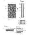
図1は、第1実施形態に係る放熱構造体の一部透過平面図(1A)、該一部透過平面図におけるA−A線断面図と一部Pの拡大図(1B)および該一部透過平面図におけるB−B線断面図と一部Qの拡大図(1C)をそれぞれ示す。
(First Embodiment)
FIG. 1 is a partially transmitted plan view (1A) of the heat radiation structure according to the first embodiment, a sectional view taken along line AA in the partially transmitted plan view, an enlarged view (1B) of a part P, and a part thereof. A sectional view taken along line BB in the transmission plan view and an enlarged view (1C) of a part of Q are shown.
第1実施形態に係る放熱構造体1は、熱源と冷却部材との間にあって、熱源から冷却部材に熱を伝導させるための放熱構造体である。放熱構造体1は、熱伝導シート11と、ゴム状弾性体12と、ゴムシート13,13と、通電用電極14,14とを備える。熱伝導シート11は、金属、炭素若しくはセラミックスの少なくとも1つにて成り、熱源と冷却部材との間にて湾曲若しくは屈曲して配置されるシートである。ゴム状弾性体12は、熱伝導シート11の湾曲若しくは屈曲にて形成される内方空間内に少なくとも配置される弾性体である。ゴムシート13,13は、熱伝導シート11と熱源とを密着固定するためのシートである。通電用電極14,14は、熱伝導シート11に通電して、熱伝導シート11自体を加熱するために熱伝導シート11上に互いに離間形成される2つ一組の電極である。ただし、通電用電極14,14は、熱伝導シート11ではなく、ゴムシート13,13若しくはゴム状弾性体12を加熱するために給電可能な電極であっても良く、そのような場合に、一方の通電用電極14から供給される電流は、ゴムシート13,13若しくはゴム状弾性体12を経由して他方の通電用電極14に流れ込んでも、あるいは通電用電極14,14同士を接続するヒータをゴムシート13,13若しくはゴム状弾性体12に形成しておき、電流が当該ヒータを流れるようにしても良い。本願でいう「炭素」は、グラファイト、グラファイトより結晶性の低いカーボンブラック、ダイヤモンド、ダイヤモンドに近い構造を持つダイヤモンドライクカーボン等の炭素(元素記号:C)から成る各種結晶構造のものを含むように広義に解釈される。
The
(1)熱伝導シート
熱伝導シート11は、この実施形態では、U字状の湾曲部を1つ備える。ただし、熱伝導シート11は、U字状の湾曲部に代えて、V字状の屈曲部を1つ備えても良い。熱伝導シート11は、好ましくは炭素製のシートであり、さらに好ましくは炭素繊維と樹脂とを含むシートである。熱伝導シート11は、本願の各実施形態では、樹脂にグラファイト繊維やカーボン粒子を配合分散した材料を硬化させた薄いシートである。樹脂が熱伝導シート11の全質量に対して50質量%を超えていても、あるいはグラファイト繊維やカーボン粒子が樹脂の全質量に対して50質量%を超えていても良い。すなわち、熱伝導シート11は、熱伝導に大きな支障が無い限り、樹脂を主材とし、あるいはグラファイト繊維やカーボン粒子を主材としても良い。樹脂としては、例えば、熱可塑性樹脂を好適に使用できる。熱可塑性樹脂としては、熱源からの熱を伝導する際に溶融しない程度の高融点を備える樹脂が好ましく、例えば、ポリフェニレンスルフィド(PPS)、ポリエーテルエーテルケトン(PEEK)、ポリアミドイミド(PAI)等を好適に挙げることができる。樹脂は、熱伝導シート11の成形前の状態において、グラファイト繊維の隙間に、例えば粒子状に分散している。熱伝導シート11は、グラファイト繊維、樹脂の他、熱伝導をより高めるためのフィラーとして、窒化アルミニウムあるいはダイヤモンドを分散していても良い。
(1) Heat Conductive Sheet The heat
熱伝導シート11は、後述のゴム状弾性体12よりも熱伝導性に優れているのが好ましく、導電性に優れるか否かは問わない。熱伝導シート11の熱伝導率は、好ましくは10W/mK以上である。この実施形態では、通電用電極14,14を用いて熱伝導シート11自体に電流が流れるようにして、熱伝導シート11を発熱させるようにしている。このため、熱伝導シート11に炭素繊維(好ましくはグラファイト繊維)やカーボン粒子を含ませて、熱伝導シート11中に電流が流れやすいネットワークを形成するようにしている。通電用電極14,14間を流れる電流がゴムシート13,13、ゴム状弾性体12あるいは別の電気回路(当該回路はヒータとして機能)を流れる場合には、熱伝導シート11は、導電性に優れている必要はなく、熱伝導性を有するだけでも良い。その場合、熱伝導シート11を、窒化アルミニウム、ダイヤモンド、ダイヤモンドカーボン(グラファイトより導電性は低い)などを含むシートとしても良い。熱伝導シート11は、湾曲性(若しくは屈曲性)のあるシートであれば、その厚さに制約はないが、0.3〜5mmが好ましく、0.3〜1mmがより好ましい。ただし、熱伝導シート11の熱伝導率は、その厚さが増加するほど低下するため、シートの強度、可撓性および熱伝導性を総合的に考慮して、その厚さを決定するのが好ましい。
The heat
(2)ゴム状弾性体
ゴム状弾性体12は、湾曲若しくは屈曲させた熱伝導シート11の内側の空間に配置される弾性体であって、熱源と冷却部材との間にあってクッション性を発揮させる機能と、熱伝導シート11に加わる荷重によって熱伝導シート11が破損等しないようにする保護部材としての機能とを有する。ゴム状弾性体12は、熱伝導シート11に比べて低熱伝導性の部材である。このため、熱源からの熱は、ゴムシート13を経た後、主に、湾曲若しくは屈曲している熱伝導シート11中を伝わって、ゴムシート13を経て、冷却部材へと伝わる。
(2) Rubber-like elastic body The rubber-like
ゴム状弾性体12は、好ましくは、シリコーンゴム、ウレタンゴム、イソプレンゴム、エチレンプロピレンゴム、天然ゴム、エチレンプロピレンジエンゴム、ニトリルゴム(NBR)あるいはスチレンブタジエンゴム(SBR)等の熱硬化性エラストマー; ウレタン系、エステル系、スチレン系、オレフィン系、ブタジエン系、フッ素系等の熱可塑性エラストマー、あるいはそれらの複合物等を含むように構成される。ゴム状弾性体12は、熱伝導シート11を伝わる熱によって溶融あるいは分解等せずにその形態を維持できる程度の耐熱性の高い材料から構成されるのが好ましい。この実施形態では、ゴム状弾性体12は、より好ましくは、ウレタン系エラストマー中にシリコーンを含浸したもの、あるいはシリコーンゴムにより構成される。ゴム状弾性体12は、その熱伝導性を少しでも高めるために、ゴム中に窒化アルミニウム、cBN、ダイヤモンドの粒子等に代表されるフィラーを分散して構成されていても良い。
The rubber-like
(3)ゴムシート
ゴムシート13,13は、この実施形態では、熱源と熱伝導シート11との間、および冷却部材と熱伝導シート11との間に配置されるシートである。ゴムシート13,13は、U字形状に湾曲した熱伝導シート11の両端から略水平を保持している領域に分離して固定されている。ただし、後述の実施形態にも示すように、U字形状に湾曲した熱伝導シート11に、その外側をU字状に覆う1つのゴムシート13を備えるようにしても良い。
(3) Rubber Sheets The
ゴムシート13は、上述のゴム状弾性体12と同様の様々な種類の弾性体にて形成可能であるが、熱源からの熱を速やかに熱伝導シート11に伝える必要から、熱伝導性に優れたシリコーンゴムを含むシートであるのが好ましい。ゴムシート13をシリコーンゴムにて主に構成する場合、窒化アルニウム、アルミニウム等の高熱伝導性のフィラーをシリコーンゴム中に分散させるのが好ましい。また、シリコーンゴム製のゴムシート13としては、粘着性を高めるために、二官能性のシリコーン生ゴムにシリコーンレジンを組み合わせたシリコーンゴムを例示できる。当該シリコーンレジンは、好適には、MQレジンを例示できる。MQレジンとは、Siの4本の結合手に酸素原子を結合させた構造の4方分岐型のQユニットだけを架橋させ、末端の反応性を止めるために、Siの1本の結合手に酸素原子を結合させた構造の一方分岐型のMユニットを加えたレジンである。また、シリコーンレジンとしては、水酸基を多く結合するものを使用した方が、シリコーンゴムの粘着性を高めることができるので好ましい。
The
ゴムシート13は、凹凸のある熱源と熱伝導シート11との密着性を高める機能を持つ。ゴムシート13は、耐熱性および粘着性があれば特に硬度を問わないが、特にシリコーンゴムを主材とするシートであれば、ショア00基準にて60度以下、好ましくは40度以下、さらに好ましくは10度以下である。ゴムシート13が低硬度であるほど、熱源の凹凸を吸収しやすいからである。また、ゴムシート13の厚さは、好ましくは0.3〜5mm、より好ましくは0.7〜3mm、さらにより好ましくは1〜2.5mmである。ただし、ゴムシート13の厚さは、熱源の凹凸あるいはゴム硬度等の条件に応じて決定するのが好ましい。
The
(4)通電用電極
通電用電極14,14は、一方を給電ラインに、他方をグランドラインにそれぞれ接続する電極である。この実施形態では、通電用電極14,14は、熱伝導シート11の表面に、金属フィラーを含有するペーストを塗布することで形成される薄膜である。金属フィラーを含有するペーストとしては、銀のフィラーを含有するペースト(銀ペースト)を好適に例示できる。その場合には、上記薄膜は銀薄膜となる。ただし、銀以外でも、比較的導電性に優れた金属材料を含有するペーストを塗布して通電用電極14,14を作製しても良い。また、通電用電極14,14の形成方法としては、特に制約はなく、例えば、刷毛塗りや、印刷を採用できる。この実施形態では、通電用電極14,14は、図1(1B)に示すように、熱伝導シート11とゴムシート13との間に形成されている。ただし、通電用電極14,14は、ゴムシート13を貫通して形成されても良い。また、ゴムシート13を形成した箇所以外に、通電用電極14,14を形成しても良い。通電用電極14,14に接続される給電用の引き出し線は、放熱構造体1に含めても、あるいは含めなくとも良い。さらに、当該引き出し線に接続される給電手段も、放熱構造体1に含めても、あるいは含めなくても良い。これは、後述の実施形態でも同様である。
(4) Energizing electrodes The energizing
(5)好適な製造方法
(a)PPS等に代表される樹脂製のファイバー、グラファイト繊維(若しくは粒子)およびカーボン粒子を水の中で撹拌して紙漉きの要領でフェルト状シートを作製する。
(b)続いて、フェルト状シートを金型内にセットして、金型内のフェルト状シート上に硬化性シリコーンゴム組成物に代表される未硬化状態のゴム状弾性体組成物を供して、加熱加圧下で成形を行う。この結果、熱伝導シート11とゴム状弾性体12とが積層された湾曲あるいは屈曲変形可能なシートが完成する。
(c)次に、熱伝導シート11側の端部に、銀ペーストを印刷して、乾燥後に通電用電極14,14を形成する。
(d)熱源および冷却部材の接する面(通電用電極14,14の位置と重ならない領域)に熱伝導性シリコーンテープを貼り付け、熱伝導シート11上にゴムシート13,13を形成する。
(e)最後に、通電用電極14,14に引き出し線を接続する。
(5) Suitable production method (a) A felt-like sheet is produced by stirring resin fibers, graphite fibers (or particles) and carbon particles typified by PPS or the like in water in the manner of papermaking.
(B) Subsequently, the felt-like sheet is set in the mold, and the uncured rubber-like elastic body composition typified by the curable silicone rubber composition is provided on the felt-like sheet in the mold. , Perform molding under heating and pressurization. As a result, a bendable or bendable sheet in which the heat
(C) Next, a silver paste is printed on the edge of the heat
(D) A heat conductive silicone tape is attached to a surface in contact with the heat source and the cooling member (a region that does not overlap with the positions of the energizing
(E) Finally, the lead wire is connected to the energizing
図2は、図1の放熱構造体を備える第1実施形態に係るバッテリーの概略断面図(2A)、該概略断面図における一部Cのバッテリーセル固定前の断面図(2B)および該概略断面図における一部Cの拡大図(2C)をそれぞれ示す FIG. 2 is a schematic cross-sectional view (2A) of the battery according to the first embodiment including the heat dissipation structure of FIG. 1, a cross-sectional view (2B) of a part C of the schematic cross-sectional view before fixing the battery cell, and the schematic cross-sectional view. An enlarged view (2C) of a part C in the figure is shown.
図2(2A)に示すバッテリー20は、例えば、電気自動車用のバッテリーであって、多数のバッテリーセル21を備える。バッテリーセル21は、アルミニウム若しくはアルミニウム基合金から成る筐体22の内底面23上に配置される。筐体22の底部24には、冷却水を流すための水冷パイプ25が備えられている。バッテリーセル21は、底部24との間に、図1の放熱構造体1を挟んで筐体22内に固定されている。このような構造のバッテリー20では、バッテリーセル21は、放熱構造体1を通じて筐体22に伝熱して、水冷によって効果的に除熱される。バッテリー20内のバッテリーセル21は、熱源の一例である。バッテリー20の底部24(水冷パイプ25を設置)は、冷却部材の一例である。
The
図2(2B)および(2C)に示すように、内底面23上に放熱構造体1を配置して、その上から多数のバッテリーセル21を配置すると、放熱構造体1はその厚さ方向の荷重を受けて圧縮される。多数のバッテリーセル21は、それらの底面が完全な平面ではなく、凹凸を有する。この実施形態では、図2(2B)に示すように、最長段差dの凹凸があるため、放熱構造体1のバッテリーセル21側のゴムシート13は、d以上の厚さを要する。一般的には、dは1mm若しくはそれ以下であると考えられている。このため、上記ゴムシート13の厚さは、1mm以上である方が好ましい。ゴムシート13の圧縮のみならず、ゴム状弾性体12も、また、多くのバッテリーセル21からの荷重を受けて、厚さt0から厚さt1(<t0)に圧縮される。バッテリーセル21の複数並列する方向は、放熱構造体1の熱伝導シート11のU字の開放側から湾曲凸部側に向かう方向であっても良く、あるいはそれと直交する方向でも良い。これは、第3実施形態以降でも同様である。
As shown in FIGS. 2B and 2C, when the
(第2実施形態)
次に、本発明の第2実施形態について説明する。第2実施形態では、第1実施形態と共通する部分については、同じ符号を付して、重複した説明を省略する。第2実施形態は、第1実施形態と同一の放熱構造体を電子機器の回路基板に搭載した形態を示す。
(Second Embodiment)
Next, the second embodiment of the present invention will be described. In the second embodiment, the parts common to the first embodiment are designated by the same reference numerals, and duplicate description will be omitted. The second embodiment shows a mode in which the same heat dissipation structure as that of the first embodiment is mounted on a circuit board of an electronic device.
図3は、第1実施形態に係る放熱構造体を回路基板とヒートシンクとの間に配置した電子機器の一部の断面図を示す。 FIG. 3 shows a cross-sectional view of a part of an electronic device in which the heat radiating structure according to the first embodiment is arranged between the circuit board and the heat sink.
電子機器30は、筐体31内にプリント回路基板(以後、「PCB」若しくは単に「回路基板」という)33を備えると共に、PCB33と所定距離を隔ててヒートシンク32を備える。ヒートシンク32は、この実施形態では、アルミニウム若しくはアルミニウム合金に代表される熱伝導性の高い金属材料から好適に構成されており、放熱を高めるための多数のフィンを備える。ヒートシンク32は、フィンに代えてあるいはフィンと共にピンを備えても良い。
The
PCB33の表側の面(図3では上方の面)および裏側の面(図3では下方の面)に描かれた配線と電気的に接続された状態の若しくは非接続状態の多くの電子部品を備えている。電子部品は、特定の部品に限定されることはなく、この実施形態では、キャパシタ34およびICチップ35を含む。この実施形態では、キャパシタ34およびICチップ35は、PCB10の表裏両面に接続されている。PCB33は、裏側の面にキャパシタ34およびICチップ35を搭載していると、ヒートシンク32の表側の面と直接接続することは難しい。このため、PCB33とヒートシンク32との隙間に放熱構造体1を配置して、回路基板33から熱伝導シート11を経てヒートシンク32に熱を伝えて効率の良い放熱を実現するようにしている。この実施形態では、回路基板33は熱源の一例である。ヒートシンク32は冷却部材の一例である。この実施形態にも示すように、放熱構造体1は、第1実施形態のようなバッテリー20のみならず、第2実施形態のような電子機器30にも搭載できる。
It is equipped with many electronic components that are electrically connected or disconnected from the wiring drawn on the front surface (upper surface in FIG. 3) and the back surface (lower surface in FIG. 3) of the
(第3実施形態)
次に、本発明の第3実施形態について説明する。第3実施形態では、第1実施形態と共通する部分については、同じ符号を付して、重複した説明を省略する。第3実施形態は、第1実施形態の放熱構造体の変形例を示す。
(Third Embodiment)
Next, a third embodiment of the present invention will be described. In the third embodiment, the parts common to the first embodiment are designated by the same reference numerals, and duplicate description will be omitted. The third embodiment shows a modified example of the heat radiating structure of the first embodiment.
図4は、第3実施形態に係る放熱構造体の湾曲変形前後の各断面図(4A)およびその変形例の同視各断面図(4B)をそれぞれ示す。 FIG. 4 shows each cross-sectional view (4A) before and after the curved deformation of the heat radiating structure according to the third embodiment and each cross-sectional view (4B) of the same view of the modified example.
第3実施形態に係る放熱構造体1aは、熱伝導シート11を湾曲変形させたときの内方空間にゴム状弾性体12aを備える。ゴム状弾性体12aは、熱伝導シート11のU字開放側から湾曲部に向かって切り込み40を備える。切り込み40の長さは、ゴム状弾性体12aを完全に分割しない長さである。この点以外の構成は、第1実施形態に係る放熱構造体1と共通する。
The
放熱構造体1aは、図4(4A)の下方に示すように、熱伝導シート11を平板として、その一方の面にゴム状弾性体12aを積層させ、その反対側の面に、ゴムシート13,13を分離して積層した構成を有する。放熱構造体1aをその長さ方向(図中の左右方向)略中央部分からゴム状弾性体12a側に折り曲げるように湾曲変形させると、図4(4A)の上方に示す形状となる。
As shown in the lower part of FIG. 4A, the
図4(4B)に示す放熱構造体1bは、放熱構造体1aの切り込み40をさらに長くした切り込み41を備える。切り込み41は、ゴム状弾性体12を、第1ゴム状弾性体12aと第2ゴム状弾性体12bとに分割している。このような切り込み41をゴム状弾性体12に形成することによっても、放熱構造体1bは、放熱構造体1aと同様に、放熱構造体1bをその長さ方向(図中の左右方向)略中央部分からゴム状弾性体12側に折り曲げるように湾曲変形させることにより、熱伝導シート11をU字状に変形させた形態の放熱構造体1bとなる。
The
このように、放熱構造体1a,1bは、ゴム状弾性体12a,12が熱伝導シート11の湾曲若しくは屈曲にて形成される内方空間内の厚さ方向にて分割されており、熱伝導シート11の湾曲若しくは屈曲を開放して平らにした際に追従可能である。
As described above, in the
(第4実施形態)
次に、本発明の第4実施形態について説明する。第4実施形態では、第1実施形態を含めた先の各実施形態と共通する部分については、同じ符号を付して、重複した説明を省略する。第4実施形態は、第1実施形態の放熱構造体の変形例を示す。
(Fourth Embodiment)
Next, a fourth embodiment of the present invention will be described. In the fourth embodiment, the parts common to each of the above embodiments including the first embodiment are designated by the same reference numerals, and duplicate description will be omitted. The fourth embodiment shows a modified example of the heat radiating structure of the first embodiment.
図5は、第4実施形態に係る放熱構造体の(1C)と同視の断面図を示す。図6は、第4実施形態に係る放熱構造体の変形例の湾曲変形前後の各断面図を示す。 FIG. 5 shows a cross-sectional view of the heat radiating structure according to the fourth embodiment, which is the same as (1C). FIG. 6 shows each cross-sectional view before and after the curved deformation of the modified example of the heat radiating structure according to the fourth embodiment.
第4実施形態に係る放熱構造体1cは、熱伝導シート11を湾曲変形した際の外側の面に同シート11の両端部に亘って1つのゴムシート13cを備える。この構造は、第1実施形態に係る放熱構造体1のようにゴムシート13,13を分割して備える構造と異なる。放熱構造体1cにおけるゴムシート13cの構成以外については、放熱構造体1と共通する。
The
また、図6に示す変形例に係る放熱構造体1dのように、ゴムシート13cを熱伝導シート11の一方の端部から他方の端部に亘って外側の面に形成するに加えて、ゴム状弾性体12aにその厚さ方向を分割する切り込み40を形成することにより、ゴム状弾性体12a、熱伝導シート11、ゴムシート13cの順に積層した平板状の放熱構造体1dを製造できる。放熱構造体1dは、その長さ方向(図中の左右方向)略中央部分からゴム状弾性体12a側に折り曲げるように湾曲変形させることにより、熱伝導シート11をU字状に変形させた形態の放熱構造体1dとなる。
Further, in addition to forming the
(第5実施形態)
次に、本発明の第5実施形態について説明する。第5実施形態では、第1実施形態を含めた先の各実施形態と共通する部分については、同じ符号を付して、重複した説明を省略する。第5実施形態は、第1実施形態の放熱構造体の変形例を示す。
(Fifth Embodiment)
Next, a fifth embodiment of the present invention will be described. In the fifth embodiment, the parts common to each of the above embodiments including the first embodiment are designated by the same reference numerals, and duplicate description will be omitted. The fifth embodiment shows a modified example of the heat radiating structure of the first embodiment.
図7は、第5実施形態に係る放熱構造体の(1C)と同視の断面図(7A)および該断面図におけるバッテリーセル固定前後の各断面図(7B)をそれぞれ示す。 FIG. 7 shows a cross-sectional view (7A) of the heat radiating structure according to the fifth embodiment and the same as (1C), and each cross-sectional view (7B) before and after fixing the battery cell in the cross-sectional view.
第5実施形態に係る放熱構造体1eは、U字状の湾曲部を2つ有する形態の熱伝導シート11eを有する。熱伝導シート11eは、(1C)と同視の断面において、略S字状の形態を有する。このように、熱伝導シートの端部から最初の湾曲部に向かう方向に切断したときの断面を略S字状の熱伝導シート11eを用いることによっても、熱源と冷却部材との間のクッション材としての機能を発揮できる。この実施形態では、ゴム状弾性体12は、熱伝導シート11eの湾曲若しくは屈曲にて形成される内方空間ごとに1つずつ配置されている。しかし、熱伝導シート11eの1つの内方空間内のみにゴム状弾性体12配置するようにしても良い。ゴムシート13,13は、熱伝導シート11eの両端における片面であってゴム状弾性体12の配置面と異なる面に形成されている。この点は、第1実施形態と同様である。
The
図7(7B)に示すように、放熱構造体1eは、その一方のゴムシート13を冷却部材の一例であるバッテリー20の底部24に、他方のゴムシート13を熱源の一例であるバッテリーセル21にそれぞれ接触するように、バッテリー20内に設置可能である。放熱構造体1eは、バッテリーセル21の荷重を受けて圧縮される。また、バッテリーセル21側のゴムシート13は、バッテリーセル21を埋設する。なお、この実施形態では、バッテリーセル21は、図7(7B)の紙面表裏方向に向かって多数並んでいる。バッテリーセル21側のゴムシート13は、多数のバッテリーセル21に段差があっても熱伝導シート11eへの伝熱効率を低下させないように、バッテリーセル21と熱伝導シート11e双方に密着している。
As shown in FIG. 7B, in the
(各実施形態の作用・効果)
以上のように、放熱構造体1,1a,1b,1c,1d,1e(以後、「放熱構造体1等」という。)は、バッテリーセル21や回路基板33のような熱源と、バッテリー20の底部24(筐体22の一部)やヒートシンク32のような冷却部材との間にあって、当該熱源から当該冷却部材に熱を伝導させるための放熱構造体であって、金属、炭素若しくはセラミックスの少なくとも1つにて成り、上記熱源と上記冷却部材との間にて湾曲若しくは屈曲して配置される熱伝導シート11,11eと、熱伝導シート11,11eの湾曲若しくは屈曲にて形成される内方空間内に少なくとも配置されるゴム状弾性体12,12aと、熱伝導シート11,11eと上記熱源とを密着固定するためのゴムシート13,13cと、熱伝導シート11,11e、ゴムシート13,13c若しくはゴム状弾性体12,12aを加熱するために給電可能な通電用電極14,14と、を備える。
(Action / effect of each embodiment)
As described above, the
放熱構造体1等を上記のように構成すると、放熱効率に優れると共に発熱機能をも備えた放熱構造体1等及びそれを備えたバッテリー20や電子機器30を実現できる。環境温度が低下して、バッテリー20の各バッテリーセル21や電子機器30の電子部品が正常に機能しない場合であっても、通電用電極14,14間に電流を流して熱伝導シート11,11e、ゴムシート13,13c若しくはゴム状弾性体12,12aを加熱することにより、各バッテリーセル21や電子部品の機能を正常に発揮できる。
When the
熱伝導シート11,11eは、U字状の湾曲部若しくはV字状の屈曲部を1以上有する形態を持つので、放熱構造体1等の厚さ方向を避け、熱伝導シート11,11eに沿って熱を伝えやすい。熱伝導シート11,11eは、放熱構造体1等中に、熱源と冷却部材との隙間において、U字状若しくはV字状に曲がりくねって配置されている。このため、熱源からの荷重を受けて熱伝導シート11,11eが破損しにくい。また、ゴム状弾性体12,12aは、放熱構造体1等のクッション性を高めるのに寄与している。
Since the heat
第3実施形態および第4実施形態におけるゴム状弾性体12,12aは、前記内方空間の厚さ方向にて分割されており、熱伝導シート11の湾曲若しくは屈曲を開放して平らにした際に追従可能である。このため、放熱構造体1等を平板状に製造しておき、その長さ方向略中央から折り曲げることによって、U字状の湾曲部若しくはV字状の屈曲部を1以上有する熱伝導シート11を容易に形成できる。
The rubber-like
熱伝導シート11,11eを炭素製のシートとすることによって、湾曲部若しくは屈曲部を1以上備える熱伝導シート11,11eを製造しやすくなる。特に、炭素製のシートを炭素繊維と樹脂とを含むシートとすることにより、可撓性に富み、湾曲あるいは屈曲させやすいシートを容易に形成できる。また、通電用電極14,14を熱伝導シート11,11e上に形成される銀薄膜とすることで、通電用電極14,14の電気抵抗を低減でき、また、容易に電極を形成できる。
By using the heat
ゴムシート13,13は、特に、シリコーンゴム製のシートとすることにより、熱伝導性が高く、かつ低硬度で熱源の凹凸を吸収可能なシートを作製しやすくなる。また、熱源からの熱によってゴムシート13,13が溶融等することなく、損傷しにくい。
By using the
上述のいずれかの放熱構造体1等を、熱源としてのバッテリーセル21と、バッテリーセル21を配置している冷却部材としての筐体22(上記実施形態では底部24)との間に配置しているバッテリー20を構成すると、バッテリーセル21が高温(60℃以上)あるいは低温(0℃以下)により発電や充電の各機能を低下させにくいバッテリー20を実現できる。
One of the above-mentioned
(その他の実施形態)
上述のように、本発明の好適な各実施形態について説明したが、本発明は、これらに限定されることなく、種々変形して実施可能である。
(Other embodiments)
As described above, the preferred embodiments of the present invention have been described, but the present invention is not limited to these, and can be implemented in various modifications.
例えば、熱源は、バッテリーセル21、回路基板33のみならず、発熱する対象物を全て含む。熱源として、例えば、キャパシタ34およびICチップ35等の電子部品を対象としても良い。同様に、冷却部材は、底部24やヒートシンク32のみならず、熱源からの熱を逃がす部材を全て含む。
For example, the heat source includes not only the
ゴム状弾性体12,12aは、上述の各実施形態では、熱伝導シート11,11eの湾曲若しくは屈曲にて形成される内方空間のみに配置されているが、当該内方空間のみならず、当該内方空間以外にも延出して形成されていても良い。例えば、ゴム状弾性体12,12aは、ゴムシート13,13c側にも回り込んで熱伝導シート11,11eに密着していても良い。
In each of the above-described embodiments, the rubber-like
ゴムシート13,13cは、熱伝導シート11,11eと熱源との間に存在していれば、熱伝導シート11,11eと冷却部材との間に存在していなくとも良い。また、ゴムシート13,13cは、熱源や冷却部材に接着していなくて、接触若しくは密着していて、熱源や冷却部材から容易に着脱できても良い。熱伝導シートは、上記各実施形態における形態ではなく、断面V字状あるいは断面コの字状のものでも良い。
The
また、上述の各実施形態の複数の構成要素は、互いに組み合わせ不可能な場合を除いて、自由に組み合わせ可能である。例えば、第2実施形態において、電子機器20に、第3実施形態、第4実施形態または第5実施形態に係る各放熱構造体1a,1b,1c.1d,1eのいずれかを備えても良い。また、切り込み40,41は、第5実施形態に係る放熱構造体1eに採用しても良い。
Further, the plurality of components of each of the above-described embodiments can be freely combined except when they cannot be combined with each other. For example, in the second embodiment, the
本発明に係る放熱構造体は、例えば、自動車用バッテリーの他、自動車、工業用ロボット、発電装置、PC、家庭用電化製品などの各種電子機器にも利用することができる。 The heat radiating structure according to the present invention can be used not only for automobile batteries but also for various electronic devices such as automobiles, industrial robots, power generation devices, PCs, and household electric appliances.
1,1a,1b,1c,1d,1e・・・放熱構造体、11,11e・・・熱伝導シート(炭素製のシート、炭素繊維と樹脂とを含むシート)、12,12a・・・ゴム状弾性体、12b・・・第1ゴム状弾性体、12c・・・第2ゴム状弾性体、13,13c・・・ゴムシート(シリコーンゴム製のシート)、14・・・通電用電極(銀薄膜)、20・・・バッテリー、21・・・バッテリーセル(熱源の一例)、22・・・筐体(冷却部材を含む)、23・・・内底面、24・・・底部(冷却部材の一例)、30・・・電子機器、31・・・筐体、32・・・ヒートシンク(冷却部材の一例)、33・・・回路基板(熱源の一例)。 1,1a, 1b, 1c, 1d, 1e ... Heat dissipation structure, 11,11e ... Heat conductive sheet (carbon sheet, sheet containing carbon fiber and resin), 12, 12a ... Rubber Elastic body, 12b ... 1st rubber elastic body, 12c ... 2nd rubber elastic body, 13, 13c ... rubber sheet (silicone rubber sheet), 14 ... energizing electrode ( (Silver thin film), 20 ... Battery, 21 ... Battery cell (an example of heat source), 22 ... Housing (including cooling member), 23 ... Inner bottom surface, 24 ... Bottom (cooling member) (Example), 30 ... Electronic equipment, 31 ... Housing, 32 ... Heat sink (example of cooling member), 33 ... Circuit board (example of heat source).
Claims (6)
金属、炭素若しくはセラミックスの少なくとも1つにて成り、前記熱源と前記冷却部材との間にて湾曲若しくは屈曲して配置される熱伝導シートと、
前記熱伝導シートの湾曲若しくは屈曲にて形成される内方空間内に少なくとも配置されるゴム状弾性体と、
前記熱伝導シートと前記熱源とを密着固定するためのゴムシートと、
前記熱伝導シート、前記ゴムシート若しくは前記ゴム状弾性体を加熱するために給電可能な通電用電極と、
を備え、
前記ゴム状弾性体は、前記内方空間の厚さ方向にて分割されており、前記熱伝導シートの湾曲若しくは屈曲を開放して平らにした際に追従可能である放熱構造体。 A heat radiating structure between a heat source and a cooling member for conducting heat from the heat source to the cooling member.
A heat conductive sheet made of at least one of metal, carbon or ceramic and arranged to be curved or bent between the heat source and the cooling member.
A rubber-like elastic body that is at least arranged in the inner space formed by bending or bending the heat conductive sheet, and
A rubber sheet for closely fixing the heat conductive sheet and the heat source,
The heat conductive sheet, the rubber sheet, or the energizing electrode capable of supplying power for heating the rubber-like elastic body,
Equipped with a,
The rubber-like elastic body is divided in the thickness direction of the inner space, and is a heat radiating structure that can follow when the heat conductive sheet is flattened by opening the curvature or bending.
前記通電用電極を前記熱伝導シート上に形成される銀薄膜とする請求項1または2に記載の放熱構造体。 The heat conductive sheet is made of carbon and is used as a carbon sheet.
The heat radiating structure according to claim 1 or 2 , wherein the current-carrying electrode is a silver thin film formed on the heat conductive sheet.
Priority Applications (1)
| Application Number | Priority Date | Filing Date | Title |
|---|---|---|---|
| JP2017161776A JP6851289B2 (en) | 2017-08-25 | 2017-08-25 | Heat dissipation structure and battery with it |
Applications Claiming Priority (1)
| Application Number | Priority Date | Filing Date | Title |
|---|---|---|---|
| JP2017161776A JP6851289B2 (en) | 2017-08-25 | 2017-08-25 | Heat dissipation structure and battery with it |
Publications (2)
| Publication Number | Publication Date |
|---|---|
| JP2019040745A JP2019040745A (en) | 2019-03-14 |
| JP6851289B2 true JP6851289B2 (en) | 2021-03-31 |
Family
ID=65727262
Family Applications (1)
| Application Number | Title | Priority Date | Filing Date |
|---|---|---|---|
| JP2017161776A Active JP6851289B2 (en) | 2017-08-25 | 2017-08-25 | Heat dissipation structure and battery with it |
Country Status (1)
| Country | Link |
|---|---|
| JP (1) | JP6851289B2 (en) |
Families Citing this family (6)
| Publication number | Priority date | Publication date | Assignee | Title |
|---|---|---|---|---|
| KR102479967B1 (en) * | 2019-05-10 | 2022-12-20 | 주식회사 엘지에너지솔루션 | Battery module |
| JP7267129B2 (en) * | 2019-07-10 | 2023-05-01 | 本田技研工業株式会社 | storage module |
| JP2021051905A (en) * | 2019-09-25 | 2021-04-01 | 富士高分子工業株式会社 | Heat conductive sheet for sealing material and heat-generating electrical/electronic part incorporated with the same |
| WO2021166346A1 (en) * | 2020-02-19 | 2021-08-26 | 信越ポリマー株式会社 | Multilayer sheet and cell unit provided with same |
| JP6916976B1 (en) * | 2020-02-19 | 2021-08-11 | 信越ポリマー株式会社 | Multi-layer sheet and cell unit with it |
| CN114725574B (en) * | 2022-06-09 | 2022-08-16 | 宜宾职业技术学院 | Cooling assembly for power battery and power battery module safety device |
Family Cites Families (10)
| Publication number | Priority date | Publication date | Assignee | Title |
|---|---|---|---|---|
| JPS5373261U (en) * | 1977-09-01 | 1978-06-19 | ||
| JPH05258842A (en) * | 1992-03-09 | 1993-10-08 | Naigai Denki Kk | Planar heating element and its manufacture |
| JPH11354166A (en) * | 1998-06-08 | 1999-12-24 | Sony Tektronix Corp | Battery temperature controller |
| JP2000022366A (en) * | 1998-06-30 | 2000-01-21 | Hitachi Denshi Ltd | Heat conduction member and cooling structure using the same |
| JP2002367757A (en) * | 2001-06-05 | 2002-12-20 | Matsushita Electric Ind Co Ltd | Heater unit |
| JP2006054356A (en) * | 2004-08-13 | 2006-02-23 | Agilent Technol Inc | Heat-conducting member |
| JP2007184392A (en) * | 2006-01-06 | 2007-07-19 | Taika:Kk | Thermoconductive structural body, and heat dissipating memeber and electronic device using the same |
| JP2015050164A (en) * | 2013-09-04 | 2015-03-16 | 三菱重工業株式会社 | Battery module |
| IL229744A0 (en) * | 2013-12-01 | 2014-03-31 | Yosi Wolf | Heat conduction device |
| JP2017135078A (en) * | 2016-01-29 | 2017-08-03 | 株式会社豊田自動織機 | Battery module and battery pack |
-
2017
- 2017-08-25 JP JP2017161776A patent/JP6851289B2/en active Active
Also Published As
| Publication number | Publication date |
|---|---|
| JP2019040745A (en) | 2019-03-14 |
Similar Documents
| Publication | Publication Date | Title |
|---|---|---|
| JP6851289B2 (en) | Heat dissipation structure and battery with it | |
| JP7001501B2 (en) | Heat dissipation structure and battery with it | |
| JP6871183B2 (en) | Heat dissipation structure and battery with it | |
| JP6929464B2 (en) | Heat dissipation structure and battery with it | |
| JP7116781B2 (en) | Heat dissipation structure and battery with same | |
| JP2019165081A (en) | Heat dissipation structure and battery equipped with the same | |
| CN213071222U (en) | Heat radiation structure and storage battery mounted with the same | |
| TW202030906A (en) | Heat dissipation structure and battery having the structure | |
| JP2019207759A (en) | Heat dissipation structure and battery | |
| JP2020113387A (en) | Heat dissipation structure and battery with the same | |
| JP6629689B2 (en) | Thermal conductive connector and electronic device having the same | |
| WO2019124178A1 (en) | Heat radiation structure, and battery provided with same | |
| JP6994122B2 (en) | Heat dissipation structure and battery with it | |
| JP7190311B2 (en) | Thermal structure and battery | |
| JP2020187885A (en) | Heat dissipation structure and battery including the same | |
| JP2021005508A (en) | Heat dissipation structure and battery including the same | |
| WO2022034759A1 (en) | Heat dissipation member, heat dissipation structure, and battery | |
| JP7174674B2 (en) | Heat dissipation structure, method for manufacturing heat dissipation structure, heat dissipation unit, method for manufacturing heat dissipation unit, and battery | |
| JP7399760B2 (en) | Heat dissipation structure and battery equipped with the same | |
| JP2021018937A (en) | Heat dissipation structure and battery comprising the same | |
| WO2020184109A1 (en) | Heat-dissipating structure sheet and method for manufacturing heat-dissipating structure | |
| NL2020306B1 (en) | Heat dissipating structure and battery provoded with the same | |
| JP2020202272A (en) | Heat dissipation structure and battery having the same | |
| JP2022012195A (en) | Heat dissipation structure and battery with the same | |
| JP2021044140A (en) | Heat dissipation structure and battery having the same |
Legal Events
| Date | Code | Title | Description |
|---|---|---|---|
| A621 | Written request for application examination |
Free format text: JAPANESE INTERMEDIATE CODE: A621 Effective date: 20200110 |
|
| A977 | Report on retrieval |
Free format text: JAPANESE INTERMEDIATE CODE: A971007 Effective date: 20200916 |
|
| A131 | Notification of reasons for refusal |
Free format text: JAPANESE INTERMEDIATE CODE: A131 Effective date: 20201006 |
|
| A521 | Request for written amendment filed |
Free format text: JAPANESE INTERMEDIATE CODE: A523 Effective date: 20201201 |
|
| TRDD | Decision of grant or rejection written | ||
| A01 | Written decision to grant a patent or to grant a registration (utility model) |
Free format text: JAPANESE INTERMEDIATE CODE: A01 Effective date: 20210302 |
|
| A61 | First payment of annual fees (during grant procedure) |
Free format text: JAPANESE INTERMEDIATE CODE: A61 Effective date: 20210309 |
|
| R150 | Certificate of patent or registration of utility model |
Ref document number: 6851289 Country of ref document: JP Free format text: JAPANESE INTERMEDIATE CODE: R150 |
|
| S531 | Written request for registration of change of domicile |
Free format text: JAPANESE INTERMEDIATE CODE: R313531 |
|
| R350 | Written notification of registration of transfer |
Free format text: JAPANESE INTERMEDIATE CODE: R350 |
|
| R250 | Receipt of annual fees |
Free format text: JAPANESE INTERMEDIATE CODE: R250 |