JP6851223B2 - Wireless communication device and communication method control method - Google Patents
Wireless communication device and communication method control method Download PDFInfo
- Publication number
- JP6851223B2 JP6851223B2 JP2017040078A JP2017040078A JP6851223B2 JP 6851223 B2 JP6851223 B2 JP 6851223B2 JP 2017040078 A JP2017040078 A JP 2017040078A JP 2017040078 A JP2017040078 A JP 2017040078A JP 6851223 B2 JP6851223 B2 JP 6851223B2
- Authority
- JP
- Japan
- Prior art keywords
- frequency band
- code
- control unit
- wireless communication
- length
- Prior art date
- Legal status (The legal status is an assumption and is not a legal conclusion. Google has not performed a legal analysis and makes no representation as to the accuracy of the status listed.)
- Active
Links
- 238000004891 communication Methods 0.000 title claims description 116
- 238000000034 method Methods 0.000 title claims description 110
- 230000005540 biological transmission Effects 0.000 claims description 63
- 238000012545 processing Methods 0.000 description 36
- 238000012937 correction Methods 0.000 description 15
- 238000005259 measurement Methods 0.000 description 7
- 238000001514 detection method Methods 0.000 description 5
- 238000007726 management method Methods 0.000 description 5
- 238000010586 diagram Methods 0.000 description 4
- 230000006870 function Effects 0.000 description 4
- 238000013468 resource allocation Methods 0.000 description 2
- 238000004088 simulation Methods 0.000 description 2
- 238000006243 chemical reaction Methods 0.000 description 1
- 238000004904 shortening Methods 0.000 description 1
Images


Landscapes
- Detection And Prevention Of Errors In Transmission (AREA)
- Mobile Radio Communication Systems (AREA)
Description
本発明は、複数の周波数帯を利用して信号を伝送する無線通信システムにおいて使用される無線通信装置および通信方式制御方法に係わる。 The present invention relates to a wireless communication device and a communication method control method used in a wireless communication system that transmits signals using a plurality of frequency bands.
無線通信システムにおいて、データは、要求される通信品質に応じた通信方式で伝送される。例えば、小さい伝送遅延が要求されるアプリケーションに対しては、受信器における復号処理に要する時間の短い符号種別および符号長が選択される。また、低い誤り率が要求されるアプリケーションに対しては、1シンボル当たりのビット数の少ない変調方式が選択される。或いは、低い誤り率が要求されるアプリケーションに対して低い符号化率が設定されるようにしてもよい。さらに、要求される通信品質に応じて、受信器における復号繰返し回数を選択してもよい。 In a wireless communication system, data is transmitted by a communication method according to the required communication quality. For example, for an application that requires a small transmission delay, a code type and a code length that require a short time for decoding processing in the receiver are selected. Further, for an application that requires a low error rate, a modulation method having a small number of bits per symbol is selected. Alternatively, a low coding rate may be set for an application that requires a low error rate. Further, the number of decoding repetitions in the receiver may be selected according to the required communication quality.
ところで、近年、通信容量を大きくするために、複数の無線周波数帯を同時に利用してデータを伝送する通信方式が検討されている。例えば、920MHz帯、2.4GHz帯、5GHz帯のうちの2つ以上の周波数帯を利用してデータが伝送されることがある。そして、複数の周波数帯を利用してデータを伝送する通信方式においては、周波数帯ごとに測定される受信レベル(RSSI:Received Signal Strength Index)及び/又は受信品質(SINR:Signal-to-Interference plus Noise Ratio)に基づいて、周波数帯ごとに、要求される通信品質に適した通信方式が選択される。 By the way, in recent years, in order to increase the communication capacity, a communication method for transmitting data by simultaneously using a plurality of radio frequency bands has been studied. For example, data may be transmitted using two or more frequency bands of the 920 MHz band, 2.4 GHz band, and 5 GHz band. In a communication method for transmitting data using a plurality of frequency bands, the reception level (RSSI: Received Signal Strength Index) and / or the reception quality (SINR: Signal-to-Interference plus) measured for each frequency band is used. Based on Noise Ratio), a communication method suitable for the required communication quality is selected for each frequency band.
また、要求される通信品質に適した通信方式を選択する技術として、複数のチャネル毎に検出された通信状況に応じて無線LANアクセスポイントの通信端末との間での無線LAN通信方式および通信チャネルを切り換える方法が提案されている(例えば、特許文献1参照)。 In addition, as a technique for selecting a communication method suitable for the required communication quality, a wireless LAN communication method and a communication channel with a communication terminal of a wireless LAN access point according to the communication status detected for each of a plurality of channels. A method of switching between the above has been proposed (see, for example, Patent Document 1).
複数の無線周波数帯を利用してデータを伝送する従来技術においては、上述のように、周波数帯ごとに通信方式が選択される。しかしながら、周波数帯ごとに通信方式を選択する場合、データ伝送効率が低下することがある。或いは、ユーザまたはアプリケーションから要求される通信品質(例えば、伝送遅延、誤り率)を満足できないことがある。すなわち、従来技術では、データ伝送効率を高くすること、及び、ユーザまたはアプリケーションから要求される通信品質を満足させることの双方をバランスよく実現することは困難である。 In the prior art of transmitting data using a plurality of radio frequency bands, a communication method is selected for each frequency band as described above. However, when the communication method is selected for each frequency band, the data transmission efficiency may decrease. Alternatively, the communication quality (for example, transmission delay, error rate) required by the user or application may not be satisfied. That is, in the prior art, it is difficult to achieve both high data transmission efficiency and satisfying the communication quality required by the user or the application in a well-balanced manner.
本発明の1つの側面に係わる目的は、要求される通信品質を満足させながらデータ伝送効率を改善することである。 An object relating to one aspect of the present invention is to improve data transmission efficiency while satisfying the required communication quality.
本発明の1つの態様の無線通信装置は、複数の周波数帯を利用して符号語を伝送する無線通信システムにおいて使用される無線通信装置であって、各周波数帯の品質、各周波数帯の使用可能リソース、データのビット長、与えられる要求品質に基づいて、前記データを伝送するための符号の種別、前記データを伝送するための符号語中の情報ビットの長さ、前記符号語の符号化率、各周波数帯の変調方式を決定する制御部と、前記制御部により決定された符号の種別および情報ビットの長さに従って、前記データを符号化して符号語を生成する符号化器と、前記制御部により決定された符号化率に従って、前記符号化器により生成された符号語の符号化率を調整する符号化率調整器と、各周波数帯に対して設けられ、前記制御部により決定された各周波数帯の変調方式に従って、与えられるビット列からそれぞれ変調信号を生成する複数の変調器と、各周波数帯の使用可能リソース、前記情報ビット長さおよび前記符号化率から算出される符号長、各周波数帯の変調方式に基づいて、前記符号化率調整器により符号化率が調整された符号語の各ビットを前記複数の変調器に分配する分配器と、を備える。 The wireless communication device of one aspect of the present invention is a wireless communication device used in a wireless communication system that transmits code words using a plurality of frequency bands, and the quality of each frequency band and the use of each frequency band. Based on the available resources, the bit length of the data, the required quality given, the type of code for transmitting the data, the length of the information bits in the code word for transmitting the data, the coding of the code word. A control unit that determines the rate, the modulation method of each frequency band, a encoder that encodes the data to generate a code word according to the type of code and the length of the information bit determined by the control unit, and the above. A coding rate adjuster that adjusts the coding rate of the code word generated by the coding device according to the coding rate determined by the control unit, and a coding rate adjuster provided for each frequency band, which is determined by the control unit. A plurality of modulators that generate a modulation signal from a given bit string according to the modulation method of each frequency band, available resources of each frequency band, a code length calculated from the information bit length and the coding rate, A distributor that distributes each bit of a code word whose coding rate has been adjusted by the coding rate regulator to the plurality of modulators based on the modulation method of each frequency band is provided.
上述の態様によれば、要求される通信品質を満足させながらデータ伝送効率を改善することができる。 According to the above aspect, the data transmission efficiency can be improved while satisfying the required communication quality.
図1は、本発明の実施形態に係わる無線通信システムの一例を示す。図1に示す無線通信システム1は、特に限定されるものではないが、例えば、無線LANシステムである。ただし、本発明の実施形態は、Bluetooth(登録商標)、WiMAX、携帯電話システム等の他の無線通信システムにも適用可能である。無線通信システム1は、無線通信装置2、3を含む。各無線通信装置2、3は、例えば、ユーザ端末である。ユーザ端末は、モバイル端末であってもよい。
FIG. 1 shows an example of a wireless communication system according to an embodiment of the present invention. The
無線通信装置2、3は、複数の周波数帯を利用してデータを伝送できる。具体的には、無線通信装置2、3は、複数の周波数帯を同時に利用してデータを伝送できる。この実施例では、無線通信装置2、3は、920MHz帯、2.4GHz帯、5GHz帯のうちの2つ以上を同時に利用してデータを伝送できる。なお、無線通信装置2、3間の通信品質は、周波数帯ごとに異なる。よって、無線通信装置2、3は、周波数帯ごとに異なる変調方式および異なる符号でデータを伝送してもよい。
The
図2は、無線通信装置2、3が備える送信回路の一例を示す。送信回路10は、この実施例では、図2に示すように、符号化器11、符号化率調整器12、分配器13、複数の変調器14a〜14c、制御部15、複数のRF回路16a〜16c、複数のアンテナ17a〜17cを備える。なお、送信回路10は、図2に示していない他の回路要素を備えていてもよい。
FIG. 2 shows an example of a transmission circuit included in the
符号化器11は、制御部15から与えられる指示に従って、入力データを符号化して1または複数の符号語を生成する。符号語は、情報ビットおよびパリティビットから構成される。入力データは、情報ビットとして符号語に格納される。入力データから複数の符号語が生成されるときは、入力データは、複数のデータブロックに分割されて各符号語に格納される。パリティビットは、入力データに基づいて生成される。なお、制御部15から符号化器11に与えられる指示は、符号の種別を表す情報および情報ビットの長さを表す情報を含む。符号の種別は、例えば、畳込み符号、低密度パリティ検査符号(LDPC:Low Density Parity Check)、ターボ符号等を識別する。情報ビットの長さは、各符号語の情報ビットの長さを表す。
The
符号化率調整器12は、制御部15から与えられる指示に従って、符号化器11により生成される符号語の符号化率を調整する。制御部15から符号化率調整器12に与えられる指示は、符号化率を表す情報を含む。符号化率は、符号語全体の長さに対する情報ビットの長さを表す。この実施例では、説明を簡単にするために、符号語全体の長さは、情報ビットの長さおよびパリティビットの長さの和に相当するものとする。
The code rate adjuster 12 adjusts the code rate of the code word generated by the
分配器13は、制御部15から与えられる指示に従って、符号化率調整器12により符号化率が調整された符号語の各ビットを変調器14a〜14cに分配する。制御部15から分配器13に与えられる指示は、各周波数帯の使用可能リソースを表す情報、符号長を表す情報、各周波数帯の変調方式を表す情報を含む。
The
変調器14a〜14cは、周波数帯ごとに設けられる。この例では、変調器14a、14b、14cは、それぞれ、920MHz帯、2.4GHz帯、5GHz帯に対して設けられる。そして、変調器14a〜14cは、それぞれ、制御部15から与えられる指示に従って、分配器13から与えられるビット列からそれぞれ変調信号を生成する。制御部15から変調器14a〜14cに与えられる指示は、変調方式を表す情報を含む。すなわち、変調器14a〜14cは、それぞれ、制御部15において決定される変調方式に応じて、入力ビット列からそれぞれ変調信号を生成する。
Modulators 14a to 14c are provided for each frequency band. In this example, the
制御部15には、制御情報が与えられる。制御情報は、データのビット長を表す情報、要求品質を表す情報を含む。データのビット長を表す情報は、例えば、そのデータを生成したアプリケーションから与えられる。要求品質を表す情報は、ユーザ、アプリケーション、またはネットワーク管理システムから与えられる。要求品質は、例えば、最大伝送遅延、最大誤り率等を表す。そして、制御部15は、各周波数帯の通信品質、各周波数帯の使用可能リソース、データのビット長、与えられる要求品質に基づいて、データを伝送するための符号の種別、データを伝送するための符号語中の情報ビットの長さ、符号語の符号化率、各周波数帯の変調方式を決定する。なお、この明細書において「伝送遅延」は、ある無線通信装置から送信される信号が他の無線通信装置により受信されて復号されるまでの時間を意味することがある。即ち、伝送遅延は、復号処理遅延を含むことがある。
Control information is given to the
制御部15は、品質測定部21およびリソース検出部22を含む。品質測定部21は、周波数帯ごとに、自装置と相手装置との間の通信品質を測定する。ただし、「測定する」は、相手装置において測定された値を取得する処理を含む。例えば、送信回路10が相手装置へ参照信号を送信したときに、相手装置は、その参照信号を利用してRSSIおよびSINRを測定する。この場合、品質測定部21は、RSSIおよびSINRの測定値を相手装置から受信することにより、自装置と相手装置との間の通信品質を測定する。ただし、品質測定部21は、他の方法で通信品質を測定してもよい。例えば、品質測定部21は、相手装置に対して参照信号の送信を依頼し、相手装置から受信する参照信号を利用してRSSIおよびSINRを測定してもよい。或いは、品質測定部21は、自装置と相手装置との間の通信品質を推定してもよい。
The
リソース検出部22は、周波数帯ごとに、使用可能な通信リソースを検出する。例えば、各周波数帯において複数のサブチャネルが提供される無線通信システムにおいては、リソース検出部22は、未使用のサブチャネルを検出してもよい。また、リソース検出部22は、使用可能な通信リソースを表す情報をネットワーク管理システムから取得してもよい。
The
制御部15は、デジタル信号を処理するプロセッサシステムまたはデジタル信号処理回路によって実現される。プロセッサシステムは、プロセッサエレメントおよびメモリを含み、与えられたプログラムを実行することにより制御部15の機能を提供する。デジタル信号処理回路は、例えば、FPGA(field-programmable gate array)であり、制御部15の機能を提供する。
The
RF回路16a〜16cは、周波数帯ごとに設けられる。この実施例では、RF回路16a、16b、16cは、それぞれ、920MHz帯、2.4GHz帯、5GHz帯に対して設けられる。そして、RF回路16a〜16cは、それぞれ、変調器14a〜14cにより生成される変調信号を対応する周波数帯にアップコンバートする。アンテナ17a〜17cは、それぞれ、RF回路16a〜16cにより生成されるRF変調信号を出力する。
RF circuits 16a to 16c are provided for each frequency band. In this embodiment, the
図3は、無線通信装置2、3が備える受信回路の一例を示す。受信回路30は、この実施例では、図3に示すように、複数のアンテナ31a〜31c、複数のダウンコンバータ32a〜32c、制御部33、複数の復調器34a〜34c、逆分配器35、符号化率逆調整器36、復号器37を備える。なお、受信回路30は、図3に示していない他の回路要素を備えていてもよい。
FIG. 3 shows an example of a receiving circuit included in the
受信回路30は、他の無線通信装置から送信される無線信号を受信する。この実施例では、受信回路30は、図2に示す送信回路10から送信される無線信号を受信する。この無線信号は、複数のアンテナ31a〜31cを介して受信され、ダウンコンバータ32a〜32cによりベースバンド帯にダウンコンバートされる。なお、ダウンコンバータ32a、32b、32cは、それぞれ、920MHz、2.4GHz、5GHzの局発信号で受信信号をダウンコンバートする。したがって、復調器34a、34b、34cには、それぞれ、920MHz帯、2.4GHz帯、5GHz帯を利用して伝送されてきた信号が導かれる。
The receiving
制御部33は、他の無線通信装置に実装される制御部15との間で制御情報を共有することにより、複数の復調器34a〜34c、逆分配器35、符号化率逆調整器36、復号器37を制御する。制御部33は、他の無線通信装置に実装される制御部15との間で、例えば、符号種別を表す情報、符号長を表す情報、符号化率を表す情報、各周波数帯の変調方式を表す情報、復号繰返し回数を表す情報を共有してもよい。送信回路10に実装される制御部15と受信回路30に実装される制御部33との間で共有される情報は、無線通信装置2、3間で直接的に通知されるようにしてもよいし、ネットワーク管理システムを介して通知されるようにしてもよい。
By sharing control information with the
制御部33は、デジタル信号を処理するプロセッサシステムまたはデジタル信号処理回路によって実現される。プロセッサシステムは、プロセッサエレメントおよびメモリを含み、与えられたプログラムを実行することにより制御部33の機能を提供する。デジタル信号処理回路は、例えば、FPGAであり、制御部33の機能を提供する。
The
復調器34a〜34cは、それぞれ、制御部33から与えられる指示に従って、対応する周波数帯の受信信号を復調する。このとき、復調器34a〜34cは、変調器14a〜14cによる変調処理に対応する復調処理を実行する。逆分配器35は、制御部33から与えられる指示に従って、復調器34a〜34cから出力されるビット列を合成する。このとき、逆分配器35は、分配器13による分配処理に対応する逆分配処理を実行する。符号化率逆調整器36は、制御部33から与えられる指示に従って、逆分配器35から出力されるビット列の符号化率を調整する。このとき、符号化率逆調整器36は、符号化率調整器12による調整処理の逆処理を実行する。
The
復号器37は、制御部33から与えられる指示に従って、符号化率逆調整器36から出力されるビット列を復号する。このとき、復号器37は、符号化器11による符号化に対応する復号処理を実行する。なお、制御部33から復号器37に与えられる指示は、復号繰返し回数を表す情報を含んでいてもよい。この場合、復号器37は、制御部33により指定される回数だけ復号処理を実行する。
The
図4は、通信方式を決定する方法の概要を示すフローチャートである。このフローチャートの処理は、送信回路10に実装されている制御部15により実行される。また、このフローチャートの処理は、例えば、他の無線通信装置へデータを送信する旨のリクエストがアプリケーションから制御部15へ与えられたときに実行される。
FIG. 4 is a flowchart showing an outline of a method for determining a communication method. The processing of this flowchart is executed by the
S1において、制御部15は、各周波数帯の品質を測定する。この実施例では、制御部15は、920MHz帯、2.4GHz帯、5GHz帯それぞれについて、RSSIおよびSINRを測定する。なお、品質の測定は、上述したように、相手装置における測定結果を取得するケースを含むものとする。
In S1, the
S2において、制御部15は、S1で測定した各周波数帯の品質に基づいて、各周波数帯で使用する変調方式を選択する。ここで、通信品質の良好な周波数帯に対しては、多値度の高い変調方式(すなわち、1シンボル当たりのビット数の多い変調方式)が選択される。一方、通信品質の悪い周波数帯に対しては、多値度の低い変調方式(すなわち、1シンボル当たりのビット数の少ない変調方式)が選択される。例えば、無線通信システムにおいてQPSKおよび16QAMが使用可能であるものとする。この場合、通信品質が所定の閾値レベルよりも低い周波数帯に対してQPSKが選択され、通信品質が所定の閾値レベル以上の周波数帯に対して16QAMが選択される。
In S2, the
S3において、制御部15は、伝送データの要求品質に応じて、符号種別および復号繰返し回数を決定する。伝送データの要求品質としては、この実施例では、最大伝送遅延および/または最大の誤り訂正能力が指定される。要求品質を表す情報は、ユーザ、アプリケーション、またはネットワーク管理システムから与えられる。
In S3, the
小さい伝送遅延が要求されたときは、制御部15は、処理時間の短い符号を選択すると共に、復号繰返し回数として小さい値を指定する。例えば、無線通信システムにおいて畳込み符号および低密度パリティ検査符号(LDPC:Low Density Parity Check)が使用可能であるものとする。ここで、復号処理に要する時間は、LDPCよりも畳込み符号の方が短い。したがって、小さい伝送遅延が要求されたときは、制御部15は、符号種別として畳込み符号を選択すると共に、復号繰返し回数として「1」を選択する。
When a small transmission delay is required, the
低い誤り率が要求されたときは、制御部15は、誤り訂正能力の高い符号を選択すると共に、復号繰返し回数として大きな値を指定する。ここで、誤り訂正能力は、畳込み符号よりもLDPCの方が高い。また、復号処理を繰返し実行することにより誤り率を改善することが可能である。したがって、低い誤り率が要求されたときは、制御部15は、符号種別としてLDPCを選択すると共に、復号繰返し回数として「64」を選択する。
When a low error rate is required, the
S4において、制御部15は、伝送データの要求品質およびリソース情報に基づいて、各周波数帯のリソース、符号長、符号化率を決定する。ここで、制御部15は、変調方式を再選択してもよい。リソース情報は、使用可能な周波数および/または使用可能な時間を表す。使用可能な周波数は、例えば、各周波数帯において複数のサブチャネルが提供される無線通信システムにおいては、未使用のサブチャネルを表す。また、使用可能な時間は、未使用のタイムスロットを表す。なお、制御部15は、ネットワーク管理システムからリソース情報を受信してもよい。
In S4, the
小さい伝送遅延が要求されたときは、制御部15は、符号長を短くすると共に、符号化率を高くする。一方、低い誤り率が要求されたときは、制御部15は、符号長を長くすると共に、符号化率を低くする。なお、一般に、符号長が短いほど復号処理に要する時間が短くなり、符号化率が低いほど誤り訂正能力が高くなる。
When a small transmission delay is required, the
次に、通信方式を決定する方法の一例を示す。以下の記載では、まず、周波数帯ごとに独立して通信方式を決定する方法を説明し、その後で本発明の実施形態に係わる方法を説明する。 Next, an example of a method for determining the communication method will be shown. In the following description, first, a method of independently determining a communication method for each frequency band will be described, and then a method according to an embodiment of the present invention will be described.
以下の例では、送信回路10は、2個の周波数帯X、Yを利用して24ビットのデータを伝送するものとする。周波数帯Xにおいては3個のサブチャネルが使用可能であり、周波数帯Yにおいては6個のサブチャネルが使用可能である。周波数帯Xの通信品質は高く、周波数帯Yの通信品質は低い。通信品質の高い周波数帯Xでは、各サブチャネルを介して16QAM信号が伝送され、通信品質の低い周波数帯Yでは、各サブチャネルを介してQPSK信号が伝送される。
In the following example, it is assumed that the
図5は、周波数帯ごとに独立して通信方式を決定する方法の一例を示す。この例では、図5(a)に示すように、周波数帯X、Yを利用してそれぞれ12ビットのデータが伝送される。周波数帯Xの通信品質は高いので、符号化率は高い(付加されるパリティビットは少ない)。よって、周波数帯Xにおいては、12ビットの情報ビットに対して8ビットのパリティが付加され、20ビットの符号語Xが生成される。一方、周波数帯Yの通信品質は低いので、符号化率は低い(付加されるパリティビットは多い)。よって、周波数帯Yにおいては、12ビットの情報ビットに対して22ビットのパリティビットが付加され、34ビットの符号語Yが生成される。 FIG. 5 shows an example of a method of independently determining a communication method for each frequency band. In this example, as shown in FIG. 5A, 12-bit data is transmitted using the frequency bands X and Y, respectively. Since the communication quality of the frequency band X is high, the coding rate is high (the number of parity bits added is small). Therefore, in the frequency band X, 8-bit parity is added to the 12-bit information bit, and a 20-bit codeword X is generated. On the other hand, since the communication quality of the frequency band Y is low, the coding rate is low (many parity bits are added). Therefore, in the frequency band Y, a 22-bit parity bit is added to the 12-bit information bit, and a 34-bit codeword Y is generated.
さらに、周波数帯Xにおいては多値度の高い変調方式(ここでは、16QAM)が適用され、周波数帯Yにおいては多値度の低い変調方式(ここでは、QPSK)が適用される。すなわち、周波数帯Xにおいては1個のシンボルに4ビットが割り当てられ、周波数帯Yにおいては1個のシンボルに2ビットが割り当てられる。この結果、周波数帯Xを利用して伝送される符号語Xは、3個の情報ビットシンボルおよび2個のパリティビットシンボルにマッピングされる。また、周波数帯Yを利用して伝送される符号語Yは、6個の情報ビットシンボルおよび11個のパリティビットシンボルにマッピングされる。なお、図5において、「I」は情報ビットを伝送する情報ビットシンボルを表し、「P」はパリティビットを伝送するパリティビットシンボルを表す。 Further, in the frequency band X, a modulation method having a high multi-level degree (here, 16QAM) is applied, and in the frequency band Y, a modulation method having a low multi-level degree (here, QPSK) is applied. That is, in the frequency band X, 4 bits are assigned to one symbol, and in the frequency band Y, 2 bits are assigned to one symbol. As a result, the codeword X transmitted using the frequency band X is mapped to three information bit symbols and two parity bit symbols. Further, the codeword Y transmitted using the frequency band Y is mapped to 6 information bit symbols and 11 parity bit symbols. In FIG. 5, "I" represents an information bit symbol for transmitting an information bit, and "P" represents a parity bit symbol for transmitting a parity bit.
符号語X、Yは、それぞれ、図5(b)に示すように、使用可能なリソースに割り当てられる。図5(b)は、各周波数帯におけるサブチャネルと単位時間(タイムスロット)に対するシンボルの割り当ての関係を示す。周波数帯Xにおいては、第1タイムスロットに3個の情報ビットシンボルが割り当てられ、第2タイムスロットに2個のパリティビットシンボルが割り当てられる。周波数帯Yにおいては、第1タイムスロットに6個の情報ビットシンボルが割り当てられ、第2タイムスロットに6個のパリティビットシンボルが割り当てられ、第3タイムスロットに5個のパリティビットシンボルが割り当てられる。なお、図5(b)において、斜線領域は、シンボルが伝送されないリソースを表している。 The codewords X and Y are assigned to available resources, respectively, as shown in FIG. 5 (b). FIG. 5B shows the relationship between subchannels and symbol assignments for unit time (time slot) in each frequency band. In the frequency band X, three information bit symbols are assigned to the first time slot, and two parity bit symbols are assigned to the second time slot. In the frequency band Y, 6 information bit symbols are assigned to the 1st time slot, 6 parity bit symbols are assigned to the 2nd time slot, and 5 parity bit symbols are assigned to the 3rd time slot. .. In FIG. 5B, the shaded area represents a resource to which the symbol is not transmitted.
このように、図5に示す例では、24ビットのデータを伝送するために、3タイムスロット期間を要する。また、受信回路30においてデータを再生するためには、符号語全体を受信する必要がある。したがって、周波数帯Xを利用して伝送される信号は、2タイムスロット期間が経過した後に復号処理が開始される。また、周波数帯Yを利用して伝送される信号は、3タイムスロット期間が経過した後に復号処理が開始される。さらに、伝送シンボルが割り当てられていない未使用のリソースが存在する。
As described above, in the example shown in FIG. 5, it takes 3 time slot periods to transmit 24-bit data. Further, in order to reproduce the data in the receiving
本発明の実施形態に係る方法においては、要求される通信品質を満足させながらデータ伝送効率が高くなるように、通信方式およびリソースの割り当てが決定される。例えば、以下の要求のうちの少なくとも1つを満足するように通信方式およびリソースの割り当てが決定される。
(1)データを伝送するために要する時間(タイムスロットの個数)を削減する
(2)受信装置において復号処理の開始タイミングを早くして復号処理遅延を削減する
(3)リソースの使用効率を高くする
すなわち、オーバヘッドを小さくすると共に、符号化利得が大きくなるように、複数の周波数帯全体で通信方式を決定する。
In the method according to the embodiment of the present invention, the communication method and resource allocation are determined so as to increase the data transmission efficiency while satisfying the required communication quality. For example, the communication method and resource allocation are determined so as to satisfy at least one of the following requirements.
(1) Reduce the time (number of time slots) required to transmit data (2) Advance the start timing of decoding processing in the receiving device to reduce decoding processing delay (3) Increase resource usage efficiency That is, the communication method is determined over the entire plurality of frequency bands so that the overhead is reduced and the coding gain is increased.
図6は、本発明の実施形態に係る送信回路10おいて通信方式を決定する方法の一例を示す。この例では、図6(a)に示すように、12ビットの情報ビットに対して12ビットのパリティビットが付加され、24ビットの符号語が生成される。この符号語の一部は周波数帯Xを利用して伝送され、残り部分は周波数帯Yを利用して伝送される。具体的には、情報ビットが周波数帯Xを利用して伝送され、パリティビットが周波数帯Yを利用して伝送される。ただし、本発明の実施形態は、図6に示す例に限定されるものではない。即ち、情報ビットが周波数帯Xおよび周波数帯Yの双方を利用して伝送されるようにしてもよいし、パリティビットが周波数帯Xおよび周波数帯Yの双方を利用して伝送されるようにしてもよい。
FIG. 6 shows an example of a method of determining a communication method in the
図5に示す例と同様に、周波数帯Xにおいて16QAMが適用され、周波数帯YにおいてQPSKが適用される。すなわち、周波数帯Xにおいては1個のシンボルに4ビットが割り当てられ、周波数帯Yにおいては1個のシンボルに2ビットが割り当てられる。この結果、周波数帯Xを利用して伝送される情報ビット(12ビット)は、3個の情報ビットシンボルにマッピングされる。周波数帯Yを利用して伝送されるパリティビット(12ビット)は、6個のパリティビットシンボルにマッピングされる。なお、図6(a)に示す符号語を2個生成することにより、24ビットのデータが伝送される。 Similar to the example shown in FIG. 5, 16QAM is applied in frequency band X and QPSK is applied in frequency band Y. That is, in the frequency band X, 4 bits are assigned to one symbol, and in the frequency band Y, 2 bits are assigned to one symbol. As a result, the information bits (12 bits) transmitted using the frequency band X are mapped to the three information bit symbols. The parity bits (12 bits) transmitted using the frequency band Y are mapped to six parity bit symbols. By generating two codewords shown in FIG. 6A, 24-bit data is transmitted.
各符号語は、図6(b)に示すように、使用可能なリソースに割り当てられる。図6(b)は、各周波数帯におけるサブチャネルと単位時間(タイムスロット)に対するシンボルの割り当ての関係を示す。この例では、1番目の符号語が第1タイムスロットに割り当てられ、2番目の符号語が第2タイムスロットに割り当てられる。すなわち、第1タイムスロットにおいて、3個の情報ビットシンボルIは、周波数帯Xの3個のサブチャネルに割り当てられ、6個のパリティビットシンボルPは、周波数帯Yの6個のサブチャネルに割り当てられる。第2タイムスロットにおいても、3個の情報ビットシンボルIは、周波数帯Xの3個のサブチャネルに割り当てられ、6個のパリティビットシンボルPは、周波数帯Yの6個のサブチャネルに割り当てられる。 Each codeword is assigned to an available resource, as shown in FIG. 6 (b). FIG. 6B shows the relationship between subchannels and symbol assignments for unit time (time slot) in each frequency band. In this example, the first codeword is assigned to the first time slot and the second codeword is assigned to the second time slot. That is, in the first time slot, the three information bit symbols I are assigned to the three subchannels of the frequency band X, and the six parity bit symbols P are assigned to the six subchannels of the frequency band Y. Be done. Also in the second time slot, the three information bit symbols I are assigned to the three subchannels of the frequency band X, and the six parity bit symbols P are assigned to the six subchannels of the frequency band Y. ..
このように、図6に示す例では、2タイムスロット期間で24ビットのデータを伝送することができる。また、この例では、1タイムスロット期間で1個の符号語全体が伝送される。すなわち、受信装置は、1タイムスロット期間が経過した時点で、復号処理を開始することができる。したがって、図5に示す方法と比較すると、復号処理遅延が削減される。さらに、図6に示す例では、第1〜第2タイムスロットにおいて、未使用のリソースが存在しない。すなわち、図5に示す方法と比較すると、リソースの使用効率が改善している。 As described above, in the example shown in FIG. 6, 24-bit data can be transmitted in a two-time slot period. Further, in this example, one codeword is transmitted in one time slot period. That is, the receiving device can start the decoding process when the one time slot period has elapsed. Therefore, the decoding processing delay is reduced as compared with the method shown in FIG. Further, in the example shown in FIG. 6, there are no unused resources in the first and second time slots. That is, the resource usage efficiency is improved as compared with the method shown in FIG.
本発明の実施形態に係る通信方式制御方法は、図6に示すように、復号処理遅延が小さく、且つ、リソースの使用効率の高くなるように、符号の種別、符号語中の情報ビットの長さ、符号化率、各周波数帯の変調方式などを決定する。以下では、これらの通信パラメータを決定する手順を説明する。 As shown in FIG. 6, the communication method control method according to the embodiment of the present invention has a code type and a length of information bits in a code word so that the decoding processing delay is small and the resource usage efficiency is high. The coding rate, the modulation method for each frequency band, etc. are determined. The procedure for determining these communication parameters will be described below.
図7は、通信方式を決定する方法の一例を示すフローチャートである。このフローチャートの処理は、図4に示すフローチャートのS2〜S4に相当する。なお、図7に示す実施例では、ユーザまたはアプリケーションにより許容可能な伝送遅延が要求されるものとする。 FIG. 7 is a flowchart showing an example of a method of determining a communication method. The processing of this flowchart corresponds to S2 to S4 of the flowchart shown in FIG. In the embodiment shown in FIG. 7, it is assumed that an acceptable transmission delay is required by the user or the application.
S11において、制御部15は、無線通信システムにおいて使用可能な複数の符号の中から、使用すべき符号を選択する。このとき、制御部15は、例えば、無線通信システムにおいて使用可能な複数の符号の中から、誤り訂正能力の最も高い符号を選択する。
In S11, the
S12において、制御部15は、情報ビット長を指定する。情報ビット長は、符号語中に格納されるデータの長さを表す。すなわち、各符号語に格納されるデータのビット数が指定される。このとき、制御部15は、例えば、情報ビット長として入力データのビット長を指定する。
In S12, the
S13において、制御部15は、各周波数帯の通信品質に基づいてMCSおよび復号繰返し回数を指定する。各周波数帯についてのMCSとしては、変調方式が指定される。例えば、通信品質が高いほど、または誤り訂正能力が高いほど、多値度の高い変調方式が指定される。換言すれば、通信品質が低いほど、または誤り訂正能力が低いほど、多値度の低い変調方式が指定される。通信品質および誤り訂正能力と変調方式との関係は、予め測定またはシミュレーション等により決められていることが好ましい。
In S13, the
また、S13において、符号化率も指定される。ただし、本発明の実施形態では、1つの符号語が複数の周波数帯を利用して伝送される。よって、符号化率は、各周波数帯に対して個々に指定されるのではなく、複数の周波数帯を利用する通信に対して指定される。また、復号繰返し回数も、複数の周波数帯を利用する通信に対して指定される。 Further, in S13, the coding rate is also specified. However, in the embodiment of the present invention, one codeword is transmitted using a plurality of frequency bands. Therefore, the coding rate is not specified individually for each frequency band, but is specified for communication using a plurality of frequency bands. The number of repetitions of decoding is also specified for communication using a plurality of frequency bands.
S14において、制御部15は、S11〜S13で選択または指定したパラメータでデータ伝送が実行されたときの伝送遅延を計算する。ここでは、伝送遅延は、受信装置において実行される復号処理に要する時間(以下、復号処理時間)を含む。そして、伝送遅延は、復号処理時間に強く依存する。尚、復号処理時間は、符号の種別に依存する。また、符号長または符号語中の情報ビット長が長いほど、復号処理時間が長くなる。さらに、復号繰返し回数が多いほど、復号処理時間が長くなる。
In S14, the
S15において、制御部15は、ユーザまたはアプリケーションにより要求される許容可能な伝送遅延(以下、要求遅延)とS14で計算した伝送遅延とを比較する。そして、S14で計算した伝送遅延が要求遅延よりも小さければ、制御部15の処理はS16へ進む。すなわち、現在のパラメータが要求品質を満足するときは、制御部15の処理はS16へ進む。なお、「現在のパラメータ」は、S11〜S13で選択または指定したパラメータを意味する。ただし、S17、S20、S22またはS23においてパラメータが更新された後は、「現在のパラメータ」は更新されたパラメータを意味する。
In S15, the
S16において、制御部15は、現在のパラメータで所定の時間内に所定量のデータを送信する場合に、余りリソースが存在するか否かを判定する。「余りリソース」は、この実施例では、未使用のリソースに相当する。例えば、図5(b)に示す例では、斜線領域で表されるリソースが余りリソースである。ここで、送信回路10は、使用可能なすべてのリソースを使用して信号を送信することが好ましい。
In S16, the
したがって、現在のパラメータで余りリソースが存在するときは、制御部15は、S17において、余りリソースが最小になるようにMCSを変更する。この場合、制御部15は、例えば、パリティビットを追加することにより符号化率を低くする。なお、符号化率を低くすると、受信装置において誤り訂正能力の改善が期待される。すなわち、余りリソースを利用してパリティビットを増やすことで、伝送遅延を大きくすることなく誤り訂正能力を改善することができる。なお、制御部15は、パリティビット長を長くすると共に、変調方式および/または符号種別を変更してもよい。
Therefore, when there is a surplus resource in the current parameter, the
現在のパラメータで余りリソースが存在しないと判定したとき、または、S17の処理が終了したときは、制御部15の処理はS18へ進む。制御部15は、S18において、送信回路10内の各回路要素にパラメータを設定する。すなわち、制御部15は、符号化器11に対して、符号の種別を表す情報および情報ビットの長さを表す情報を設定する。制御部15は、符号化率調整器12に対して、符号化率を表す情報を設定する。制御部15は、分配器13に対して、各周波数帯の使用可能リソースを表す情報、符号長を表す情報、各周波数帯の変調方式を表す情報を設定する。制御部15は、変調器14a〜14cに対して、変調方式を表す情報を設定する。また、制御部15は、決定したパラメータを受信回路30へ通知する。このとき、制御部15は復号繰返し回数を表す情報も受信回路30へ通知する。
When it is determined that there are not many resources in the current parameter, or when the processing of S17 is completed, the processing of the
現在のパラメータに基づいてS14で計算した伝送遅延が要求遅延よりも大きければ(S15:No)、制御部15は、伝送遅延を小さくするためにS19〜S23の処理を実行する。すなわち、S19において、制御部15は、現在のパラメータとして指定されている復号繰返し回数が1であるか否かを判定する。復号繰返し回数が2以上であるとき
は、制御部15は、S20において、復号繰返し回数を少なくする。このとき、制御部15は、例えば、復号繰返し回数を1だけ少なくする。
If the transmission delay calculated in S14 based on the current parameters is larger than the required delay (S15: No), the
この後、制御部15の処理はS13に戻り、MCSが再選択される。すなわち、S13〜S15、S19、S20において、復号繰返し回数を削減することで伝送遅延が要求遅延よりも小さくなったか否かが判定される。この処理ループは、伝送遅延が要求遅延よりも小さくなるまで繰り返し実行される。ただし、復号繰返し回数が1であるにもかかわらず伝送遅延が要求遅延以上である場合には、制御部15の処理はS21へ進む。
After that, the process of the
S21において、制御部15は、現在のパラメータとして指定されている情報ビット長が、選択されている符号種別での最小の情報ビット長であるか否かを判定する。ここで、情報ビット長が小さければ、符号長も短くなり、伝送遅延の削減が期待される。そこで、現在のパラメータとして指定されている情報ビット長が最小のビット長でないときは、制御部15は、S22において情報ビット長を短くする。すなわち、入力データを分割することにより、各符号語中に格納するデータの長さを短くする。
In S21, the
この後、制御部15の処理はS13に戻り、MCSが再選択される。すなわち、S13〜S15、S21、S22において、情報ビット長を短くすることで伝送遅延が要求遅延よりも小さくなったか否かが判定される。この処理ループは、伝送遅延が要求遅延よりも小さくなるまで繰り返し実行される。ただし、情報ビット長が最小のビット長まで削減されたにもかかわらず伝送遅延が要求遅延以上である場合には、制御部15の処理はS23へ進む。
After that, the process of the
S23において、制御部15は、符号種別を変更する。この場合、復号処理時間の短い符号が新たに選択される。例えば、LDPCでは伝送遅延が要求遅延以上であるときは、畳込み符号が選択される。
In S23, the
この後、制御部15の処理はS12に戻る。この場合、新たに選択された符号に対してS13以降の処理が実行されるので、S12において、情報ビット長の初期値が指定される。例えば、制御部15は、情報ビット長として入力データのビット長を指定する。
そして、符号種別を変更することで伝送遅延が要求遅延よりも小さくなったか否かが判定される。この処理ループは、伝送遅延が要求遅延よりも小さくなるまで繰り返し実行される。
After that, the process of the
Then, by changing the code type, it is determined whether or not the transmission delay is smaller than the required delay. This processing loop is repeatedly executed until the transmission delay becomes smaller than the required delay.
図6に示すケースを参照して図7に示すフローチャートの実施例を説明する。以下の記載では、入力データは24ビットであるものとする。
S11において、所定の符号種別(以下、符号A)が選択される。S12において、情報ビット長として24ビットが指定される。S13において、周波数帯Xに対して16QAMが指定され、周波数帯Yに対してQPSKが指定される。また、復号繰返し回数としてN(Nは、2以上の整数)が指定される。S14〜S15において、伝送遅延が要求遅延よりも大きいものとする。この場合、S19〜S20において、復号繰返し回数がNから1に変更された後、制御部15の処理はS13に戻り、MCSが再選択される。
An embodiment of the flowchart shown in FIG. 7 will be described with reference to the case shown in FIG. In the following description, it is assumed that the input data is 24 bits.
In S11, a predetermined code type (hereinafter, code A) is selected. In S12, 24 bits are specified as the information bit length. In S13, 16QAM is designated for the frequency band X, and QPSK is designated for the frequency band Y. Further, N (N is an integer of 2 or more) is specified as the number of repetitions of decoding. In S14 to S15, it is assumed that the transmission delay is larger than the required delay. In this case, in S19 to S20, after the number of decoding repetitions is changed from N to 1, the processing of the
S13において、必要に応じてMCSが変更される。ここで、S14〜S15において、再度、伝送遅延が要求遅延よりも大きいものとする。この場合、S21〜S22において、情報ビット長が24から12に変更された後、制御部15の処理はS13に戻り、MCSが再選択される。
In S13, the MCS is changed as needed. Here, in S14 to S15, it is assumed that the transmission delay is larger than the required delay again. In this case, in S21 to S22, after the information bit length is changed from 24 to 12, the processing of the
S13において、必要に応じてMCSが変更される。S14〜S15において、再度、伝送遅延が要求遅延よりも大きいものとする。この場合、S23において、符号種別が符号Aから符号Bに変更された後、制御部15の処理はS12に戻る。なお、符号Aと比較して、符号Bの復号処理時間は短いものとする。そして、符号種別が符号Aから符号Bに変更されたことにより、S14〜S15において、伝送遅延が要求遅延よりも小さいものとする。ここで、S16の判定条件が「余りリソースが最小」であるものとする。そうすると、図6に示す例では、S16の判定結果が「Yes」となる。
In S13, the MCS is changed as needed. In S14 to S15, it is assumed that the transmission delay is larger than the required delay again. In this case, in S23, after the code type is changed from the code A to the code B, the processing of the
この後、S18において、データ伝送の準備が実行される。すなわち、符号化器11に対して「符号の種別:符合B」「情報ビット長:12」が設定される。符号化率調整器12に対して「符号化率:1/2」が設定される。分配器13に対して「周波数帯X:3サブチャネル、16QAM」「周波数帯Y:6サブチャネル、QPSK」「符号長:24」が設定される。周波数帯Xに対応する変調器(例えば、変調器14a)に対して「変調方式:16QAM」が設定され、周波数帯Yに対応する変調器(例えば、変調器14b)に対して「変調方式:QPSK」が設定される。
After that, in S18, preparation for data transmission is executed. That is, "code type: code B" and "information bit length: 12" are set for the
図8は、変調方式による特性の差異を説明する図である。ここでは、誤り訂正を行わないケースにおいて、多値度の異なる変調方式のビット誤り率(BER)を比較している。尚、BPSK、QPSK、8PSK、16QAM、64QAMの多値度(1シンボル当たり伝送されるビット数)は、それぞれ1、2、3、4、6である。そして、例えば、QPSK、16QAM、64QAMにおいて、ビット誤り率が1パーセントとなる信号対雑音比は、それぞれ、8dB、14dB、22dBである。すなわち、多値度が高い変調方式ほど、高い信号対雑音比が要求される。したがって、通信品質が良好な周波数帯においては、多値度の高い変調方式を使用することができ、通信品質が悪い周波数帯においては、多値度の低い変調方式しか使用することができない。 FIG. 8 is a diagram for explaining the difference in characteristics depending on the modulation method. Here, the bit error rates (BER) of modulation methods having different multivalue degrees are compared in the case where error correction is not performed. The multilevel degrees (number of bits transmitted per symbol) of BPSK, QPSK, 8PSK, 16QAM, and 64QAM are 1, 2, 3, 4, and 6, respectively. Then, for example, in QPSK, 16QAM, and 64QAM, the signal-to-noise ratios at which the bit error rate is 1% are 8 dB, 14 dB, and 22 dB, respectively. That is, the higher the multi-value degree, the higher the signal-to-noise ratio is required. Therefore, in the frequency band where the communication quality is good, the modulation method having a high multi-value degree can be used, and in the frequency band where the communication quality is poor, only the modulation method having a low multi-value degree can be used.
図9は、符号の種別による特性の差異を説明する図である。ここでは、誤り訂正を行わないケース、畳込み符号を使用するケース、LDPCを使用するケースについてパケット誤り率(PER)を比較している。図9に示すように、誤り訂正を実行することにより所要SNRが低くなる。また、LDPCの誤り訂正能力は、畳込み符号よりも高い。但し、畳込み符号と比較してLDPCの復号処理時間は長くなる。したがって、これらの符号を使用可能な無線通信システムでは、小さな伝送遅延が要求されるときは畳込み符号が選択され、低い誤り率が要求されるときはLDPCが選択される。 FIG. 9 is a diagram for explaining the difference in characteristics depending on the type of reference numeral. Here, the packet error rate (PER) is compared for the case where error correction is not performed, the case where a convolutional code is used, and the case where LDPC is used. As shown in FIG. 9, the required SNR is lowered by performing error correction. Moreover, the error correction capability of the LDPC is higher than that of the convolutional code. However, the decoding processing time of the LDPC is longer than that of the convolutional code. Therefore, in wireless communication systems that can use these codes, a convolutional code is selected when a small transmission delay is required, and an LDPC is selected when a low error rate is required.
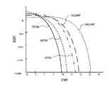
図10は、符号長および符号化率による特性の差異を説明する図である。ここでは、符号長(L=512、1024、2048、4096)および符号化率(R=1/3、1/2、2/3、3/4)に対してパケット誤り率を比較している。図10に示すように、符号長が長いほどPER特性が向上し、符号化率が低くなるほどPER特性が向上する。ただし、符号化率が低くなると、パリティビットの割合が高くなるので、実効データレートは低下する。 FIG. 10 is a diagram for explaining the difference in characteristics depending on the code length and the coding rate. Here, the packet error rate is compared with respect to the code length (L = 512, 1024, 2048, 4096) and the coding rate (R = 1/3, 1/2, 2/3, 3/4). .. As shown in FIG. 10, the longer the code length, the better the PER characteristic, and the lower the coding rate, the better the PER characteristic. However, when the coding rate is low, the ratio of the parity bits is high, so that the effective data rate is low.
図11は、復号繰返し回数による特性の差異を説明する図である。ここでは、復号繰返し回数に対してビット誤り率を比較している。図11に示すように、復号繰返し回数を多くすると、誤り訂正能力が向上する。ただし、復号繰返し回数を多くすると、必然的に復号処理時間が増加するので、伝送遅延が大きくなってしまう。 FIG. 11 is a diagram illustrating a difference in characteristics depending on the number of repetitions of decoding. Here, the bit error rate is compared with respect to the number of repetitions of decoding. As shown in FIG. 11, increasing the number of decoding repetitions improves the error correction capability. However, if the number of times of decoding repetition is increased, the decoding processing time inevitably increases, so that the transmission delay becomes large.
図8〜図11に示す特性は、予め測定またはシミュレーションにより得られている。そして、制御部15は、図8〜図11に示す特性を利用して、図7に示すフローチャートの処理を実行する。
The characteristics shown in FIGS. 8 to 11 are obtained in advance by measurement or simulation. Then, the
1 無線通信システム
2、3 無線通信装置
10 送信回路
11 符号化器
12 符号化率調整器
13 分配器
14a〜14c 変調器
15 制御部
16a〜16c RF回路
17a〜17c アンテナ
21 品質測定部
22 リソース検出部
30 受信回路
31a〜31c アンテナ
32a〜32c ダウンコンバータ
33 制御部
34a〜34c 復調器
35 逆分配器
36 符号化率逆調整器
37 復号器
1
Claims (7)
制御部と、
前記制御部により決定された符号の種別および情報ビットの長さに従って、データを符号化して符号語を生成する符号化器と、
前記制御部により決定された符号化率に従って、前記符号化器により生成された符号語の符号化率を調整する符号化率調整器と、
各周波数帯に対して設けられ、前記制御部により決定された各周波数帯の変調方式に従って、与えられるビット列からそれぞれ変調信号を生成する複数の変調器と、
各周波数帯の使用可能リソース、前記情報ビットの長さおよび前記符号化率から算出される符号長、各周波数帯の変調方式に基づいて、前記符号化率調整器により符号化率が調整された符号語の各ビットを前記複数の変調器に分配する分配器と、を備え、
前記制御部は、
各周波数帯の品質に基づいて各周波数帯の変調方式を決定し、
データの要求品質に基づいて前記データを伝送するための符号の種別および前記データを伝送するための符号語中の情報ビットの長さを決定し、
前記要求品質および各周波数帯の使用可能リソースに基づいて、前記符号語の符号化率を決定する
ことを特徴とする無線通信装置。 A wireless communication device used in a wireless communication system that transmits code words using a plurality of frequency bands.
And the control section,
According to the length of the classification and the information bits of the code determined by the control unit, and an encoder for generating a code word data is encoded,
A code rate adjuster that adjusts the code rate of the codeword generated by the coder according to the code rate determined by the control unit.
A plurality of modulators provided for each frequency band and each generating a modulation signal from a given bit string according to the modulation method of each frequency band determined by the control unit.
The code rate was adjusted by the code rate adjuster based on the available resources of each frequency band, the length of the information bit, the code length calculated from the code rate, and the modulation method of each frequency band. A distributor that distributes each bit of a code word to the plurality of modulators is provided.
The control unit
Determine the modulation method for each frequency band based on the quality of each frequency band,
Based on the required quality of the data, the type of code for transmitting the data and the length of the information bit in the code word for transmitting the data are determined.
The code rate of the codeword is determined based on the required quality and the available resources of each frequency band.
A wireless communication device characterized by the fact that.
ことを特徴とする請求項1に記載の無線通信装置。 Wherein, based on the required quality and available resources of the frequency band of the data, the wireless communication apparatus according to claim 1, characterized in that re-determines a modulation scheme for each frequency band.
受信器に通知する
ことを特徴とする請求項1に記載の無線通信装置。 The control unit determines the type of code, the length of information bits, the coding rate, and the modulation method for each frequency band.
The wireless communication device according to claim 1, wherein the receiver is notified.
ことを特徴とする請求項3に記載の無線通信装置。 The control unit further determines the number of decoding repetitions for decoding the modulated signal in the receiver based on the given required quality, and notifies the receiver of the determined number of decoding repetitions. The wireless communication device according to claim 3.
前記制御部は、許容可能な伝送遅延に基づいて、前記符号語中の情報ビットのビット長を決定する
ことを特徴とする請求項1乃至4のうち何れか1項に記載の無線通信装置。 The required quality is an acceptable transmission delay,
The wireless communication device according to any one of claims 1 to 4, wherein the control unit determines the bit length of the information bit in the codeword based on an acceptable transmission delay.
前記制御部は、許容可能な伝送遅延に基づいて、符号の種別を決定する
ことを特徴とする請求項1乃至4のうち何れか1項に記載の無線通信装置。 The required quality is an acceptable transmission delay,
The wireless communication device according to any one of claims 1 to 4, wherein the control unit determines a code type based on an acceptable transmission delay.
各周波数帯の品質に基づいて各周波数帯の変調方式を決定し、
データの要求品質に基づいて前記データを伝送するための符号の種別および前記データを伝送するための符号語中の情報ビットの長さを決定し、
前記要求品質および各周波数帯の使用可能リソースに基づいて、前記符号語の符号化率を決定し、
決定した符号の種別および情報ビットの長さに従って、前記データを符号化して符号語を生成し、
決定した符号化率に従って、前記符号語の符号化率を調整し、
前記各周波数帯の使用可能リソース、決定した情報ビットの長さおよび符号化率から算出される符号長、決定した各周波数帯の変調方式に基づいて、符号化率が調整された前記符号語の各ビットを、前記複数の周波数帯に分配し、
決定した各周波数帯の変調方式に従って、前記複数の周波数帯に分配された各ビット列からそれぞれ変調信号を生成する、
ことを特徴とする通信方式制御方法。 A communication method control method for controlling a communication method for each frequency band in a wireless communication device used in a wireless communication system that transmits code words using a plurality of frequency bands.
Determine the modulation method for each frequency band based on the quality of each frequency band,
Based on the required quality of the data, the type of code for transmitting the data and the length of the information bit in the code word for transmitting the data are determined.
The code rate of the codeword is determined based on the required quality and the available resources of each frequency band.
The data is encoded to generate a code word according to the determined code type and the length of the information bit.
The coding rate of the codeword is adjusted according to the determined code rate.
The available resources, the code length calculated from the determined length of the information bits and the coding rate of each frequency band, based on the modulation scheme of each frequency band determined, the codeword encoding rate is adjusted Each bit is distributed to the plurality of frequency bands,
A modulation signal is generated from each bit string distributed in the plurality of frequency bands according to the determined modulation method of each frequency band.
A communication method control method characterized by the fact that.
Priority Applications (1)
| Application Number | Priority Date | Filing Date | Title |
|---|---|---|---|
| JP2017040078A JP6851223B2 (en) | 2017-03-03 | 2017-03-03 | Wireless communication device and communication method control method |
Applications Claiming Priority (1)
| Application Number | Priority Date | Filing Date | Title |
|---|---|---|---|
| JP2017040078A JP6851223B2 (en) | 2017-03-03 | 2017-03-03 | Wireless communication device and communication method control method |
Publications (2)
| Publication Number | Publication Date |
|---|---|
| JP2018148328A JP2018148328A (en) | 2018-09-20 |
| JP6851223B2 true JP6851223B2 (en) | 2021-03-31 |
Family
ID=63591580
Family Applications (1)
| Application Number | Title | Priority Date | Filing Date |
|---|---|---|---|
| JP2017040078A Active JP6851223B2 (en) | 2017-03-03 | 2017-03-03 | Wireless communication device and communication method control method |
Country Status (1)
| Country | Link |
|---|---|
| JP (1) | JP6851223B2 (en) |
-
2017
- 2017-03-03 JP JP2017040078A patent/JP6851223B2/en active Active
Also Published As
| Publication number | Publication date |
|---|---|
| JP2018148328A (en) | 2018-09-20 |
Similar Documents
| Publication | Publication Date | Title |
|---|---|---|
| US10887150B2 (en) | Method and apparatus for data transmission in a multiuser downlink cellular system | |
| CN109803426B (en) | Method and device for transmitting data | |
| JP5264923B2 (en) | Method and apparatus for transmitting channel quality information in a wireless communication system | |
| US9166736B2 (en) | Communication apparatus and communication method | |
| JP4908506B2 (en) | Method and apparatus for optimal selection of MIMO and interference cancellation | |
| US7277498B2 (en) | Mapping method of code word with QAM modulation | |
| JP2001244912A (en) | Cdma cellular radio transmission system | |
| EP1285507B1 (en) | Data transfer method | |
| KR20080013966A (en) | Transmitting apparatus, receiving apparatus and transmission power control method | |
| EP2299737A1 (en) | Base station apparatus and data mapping method | |
| EP1879319A1 (en) | Transmitting apparatus, receiving apparatus and spatial multiplex number controlling method | |
| JP2006340364A (en) | Transmit power control of wireless communication device | |
| KR102142363B1 (en) | Base station apparatus, terminal apparatus, wireless communication system and method for controlling wireless communication system | |
| US8165537B2 (en) | Wireless transmitter and wireless transmission method | |
| JPWO2007125580A1 (en) | Adaptive modulation method and communication apparatus | |
| JPWO2009019759A1 (en) | Base station apparatus, uplink SINR measurement method, uplink scheduling method, and reception quality measurement method | |
| CN113949471A (en) | Measurement feedback method and device | |
| JP5386513B2 (en) | Communication apparatus and reception quality reporting method | |
| JP6851223B2 (en) | Wireless communication device and communication method control method | |
| CN115276908A (en) | Wireless communication method and device, and storage medium | |
| KR102124610B1 (en) | Method and apparatus for low complexity decoding in a wireless communication systems | |
| US9363760B2 (en) | Method and system allowing the dynamic allocation of power and/or of modulation in a system comprising N channels | |
| RU2430470C1 (en) | Method and apparatus for transmitting channel quality information in telecommunication system | |
| KR102335920B1 (en) | Apparatus and method for selecting channel quality indicator in communication system | |
| JPWO2020090067A1 (en) | Base station equipment, terminal equipment and wireless communication systems |
Legal Events
| Date | Code | Title | Description |
|---|---|---|---|
| RD01 | Notification of change of attorney |
Free format text: JAPANESE INTERMEDIATE CODE: A7426 Effective date: 20170310 |
|
| A521 | Request for written amendment filed |
Free format text: JAPANESE INTERMEDIATE CODE: A821 Effective date: 20170310 |
|
| A621 | Written request for application examination |
Free format text: JAPANESE INTERMEDIATE CODE: A621 Effective date: 20200226 |
|
| RD03 | Notification of appointment of power of attorney |
Free format text: JAPANESE INTERMEDIATE CODE: A7423 Effective date: 20200702 |
|
| A977 | Report on retrieval |
Free format text: JAPANESE INTERMEDIATE CODE: A971007 Effective date: 20201016 |
|
| A131 | Notification of reasons for refusal |
Free format text: JAPANESE INTERMEDIATE CODE: A131 Effective date: 20201110 |
|
| A521 | Request for written amendment filed |
Free format text: JAPANESE INTERMEDIATE CODE: A523 Effective date: 20210104 |
|
| TRDD | Decision of grant or rejection written | ||
| A01 | Written decision to grant a patent or to grant a registration (utility model) |
Free format text: JAPANESE INTERMEDIATE CODE: A01 Effective date: 20210224 |
|
| A61 | First payment of annual fees (during grant procedure) |
Free format text: JAPANESE INTERMEDIATE CODE: A61 Effective date: 20210309 |
|
| R150 | Certificate of patent or registration of utility model |
Ref document number: 6851223 Country of ref document: JP Free format text: JAPANESE INTERMEDIATE CODE: R150 |
|
| S531 | Written request for registration of change of domicile |
Free format text: JAPANESE INTERMEDIATE CODE: R313531 |
|
| R350 | Written notification of registration of transfer |
Free format text: JAPANESE INTERMEDIATE CODE: R350 |
|
| R250 | Receipt of annual fees |
Free format text: JAPANESE INTERMEDIATE CODE: R250 |