JP6848821B2 - Press molding equipment and method - Google Patents
Press molding equipment and method Download PDFInfo
- Publication number
- JP6848821B2 JP6848821B2 JP2017220550A JP2017220550A JP6848821B2 JP 6848821 B2 JP6848821 B2 JP 6848821B2 JP 2017220550 A JP2017220550 A JP 2017220550A JP 2017220550 A JP2017220550 A JP 2017220550A JP 6848821 B2 JP6848821 B2 JP 6848821B2
- Authority
- JP
- Japan
- Prior art keywords
- punch
- vertical wall
- flange
- molding
- die
- Prior art date
- Legal status (The legal status is an assumption and is not a legal conclusion. Google has not performed a legal analysis and makes no representation as to the accuracy of the status listed.)
- Active
Links
- 238000000465 moulding Methods 0.000 title claims description 220
- 238000000034 method Methods 0.000 title claims description 62
- 230000007246 mechanism Effects 0.000 claims description 49
- 238000003825 pressing Methods 0.000 claims description 25
- 238000005452 bending Methods 0.000 description 21
- 230000008569 process Effects 0.000 description 21
- 238000013461 design Methods 0.000 description 5
- 230000008859 change Effects 0.000 description 4
- 238000011156 evaluation Methods 0.000 description 4
- 239000000463 material Substances 0.000 description 4
- 238000005259 measurement Methods 0.000 description 4
- 238000004891 communication Methods 0.000 description 3
- 238000010586 diagram Methods 0.000 description 3
- 230000001629 suppression Effects 0.000 description 3
- 229910000831 Steel Inorganic materials 0.000 description 2
- 230000000052 comparative effect Effects 0.000 description 2
- 230000007423 decrease Effects 0.000 description 2
- 230000000694 effects Effects 0.000 description 2
- 238000004519 manufacturing process Methods 0.000 description 2
- 230000035515 penetration Effects 0.000 description 2
- 238000012545 processing Methods 0.000 description 2
- 230000009467 reduction Effects 0.000 description 2
- 239000010959 steel Substances 0.000 description 2
- 230000009471 action Effects 0.000 description 1
- 230000008901 benefit Effects 0.000 description 1
- 230000008602 contraction Effects 0.000 description 1
- 230000007547 defect Effects 0.000 description 1
- 238000011161 development Methods 0.000 description 1
- 238000002474 experimental method Methods 0.000 description 1
- 238000010097 foam moulding Methods 0.000 description 1
- 238000002360 preparation method Methods 0.000 description 1
- 230000002035 prolonged effect Effects 0.000 description 1
- 238000011084 recovery Methods 0.000 description 1
- 230000000717 retained effect Effects 0.000 description 1
- 239000013585 weight reducing agent Substances 0.000 description 1
Images


Description
本発明は、長手方向に延びる溝形状部を有し、該溝形状部を形成する一対の縦壁部の少なくとも一方に長手方向に沿って湾曲するフランジ部を有する目標形状の成形品を成形するプレス成形装置及び方法に関する。 The present invention forms a molded product having a target shape having a groove-shaped portion extending in the longitudinal direction and having a flange portion curved along the longitudinal direction on at least one of a pair of vertical wall portions forming the groove-shaped portion. Regarding press molding equipment and methods.
プレス成形とは、その対象物である材料(ブランク)に金型を押し付けることにより、金型の形状をブランクに転写して加工を行う方法のことである。プレス成形においては、プレス成形品を金型から取り出した後に、そのプレス成形品内の残留応力が弾性回復することによって起こる形状不良、いわゆるスプリングバックが発生し、所望の形状とは異なってしまう問題がしばしば発生する。 Press molding is a method of transferring the shape of a die to a blank by pressing the die against the material (blank) which is the object thereof. In press molding, after the press-molded product is taken out from the mold, shape defects, so-called springbacks, which occur due to elastic recovery of the residual stress in the press-molded product, occur, and the shape is different from the desired shape. Often occurs.
スプリングバックがどの程度生じるかについては、主に材料の強度に大きく影響される。昨今では、特に自動車業界を中心に、自動車車体の軽量化の観点から車体部品に高強度な鋼板を使用する傾向が強くなっており、このような材料の高強度化に伴いスプリングバックの生じる程度が大きくなっている。
このため、スプリングバック後の形状を目標とする設計形状に近づけるために、生産現場では熟練者が金型を幾度も修正して、トライアル&エラーを重ねなければならず、その結果、生産準備期間が長期化してしまう。したがって、スプリングバックを効果的に低減できる方法を開発することは、自動車の開発期間やコストを削減する上でも、ますます重要な課題であると言える。
The extent to which springback occurs is largely influenced by the strength of the material. In recent years, especially in the automobile industry, there is a strong tendency to use high-strength steel plates for car body parts from the viewpoint of weight reduction of automobile bodies, and the degree of springback caused by such high-strength materials is increasing. Is getting bigger.
For this reason, in order to bring the shape after springback closer to the target design shape, a skilled worker must modify the mold many times at the production site and repeat trials and errors, resulting in a production preparation period. Will be prolonged. Therefore, it can be said that developing a method that can effectively reduce springback is an increasingly important issue in reducing the development period and cost of automobiles.
スプリングバックの低減には、その発生原因である応力のコントロールが必要不可欠である。部品形状の断面が長手方向に変化しないストレート部品では、スプリングバックは口開きなどの2次元的な断面形状の変化にとどまり、応力のコントロールは比較的容易である。一方、部品形状の断面が長手方向に変化する湾曲した部品では、2次元的な断面形状の変化に加え、捩れや曲がりといった3次元的なスプリングバックが発生する。3次元的なスプリングバックを引き起こす応力は複雑で、その制御は極めて困難である。
湾曲部品の捩れや曲がりの3次元的なスプリングバックを低減する技術として、特許文献1に「プレス成形方法及び装置」が提案されている。
In order to reduce springback, it is essential to control the stress that causes it. In a straight part in which the cross section of the part shape does not change in the longitudinal direction, the springback is limited to a two-dimensional change in the cross-sectional shape such as opening of the mouth, and stress control is relatively easy. On the other hand, in a curved part in which the cross section of the part shape changes in the longitudinal direction, in addition to the two-dimensional change in the cross-sectional shape, a three-dimensional springback such as twisting or bending occurs. The stresses that cause three-dimensional springback are complex and extremely difficult to control.
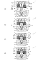
同文献においては、例えば図9に示すようなパンチ底部51aと縦壁部51b、51cからなる溝形状部51dおよびフランジ部(湾曲内側フランジ部51eおよび湾曲外側フランジ部51f)で形成され、かつ長手方向に沿って湾曲するフランジ部を有する成形品51をフォーム成形した際に成形品51に生じるスプリングバックの形態について検討されている。
本発明は、同文献で検討されたスプリングバック低減のメカニズムを前提としているので、以下において同文献で検討されたメカニズムを概説する。
In the same document, for example, it is formed by a groove-
Since the present invention is premised on the mechanism of springback reduction examined in the same document, the mechanism examined in the same document will be outlined below.
従来の単純なフォーム成形では、図10の斜視図、図11の断面図に示すように、ダイ53とパンチ55を有するプレス成形金型57でブランク69(図11参照)を挟み込むことで成形を行う。図12は成形前後のブランク外形線を示した図であり、破線が成形前のブランク外形線を、実線が下死点でのブランク外形線を示している。湾曲曲率の大きい側(曲率半径の小さい側)のフランジ部(以下、湾曲内側フランジ部51e)に該当する外形線は成形によりブランクが流入することで曲率は小さくなり(曲率半径は大きくなり)線長が長くなる(A0B0→A1B1)。つまり、湾曲内側フランジ部51eは伸びフランジ成形となり、下死点では長手方向に引張応力が残留する。
In the conventional simple foam molding, as shown in the perspective view of FIG. 10 and the cross-sectional view of FIG. 11, molding is performed by sandwiching the blank 69 (see FIG. 11) between the press molding dies 57 having the
一方、湾曲曲率の小さい側(曲率半径の大きい側)のフランジ部(以下、湾曲外側フランジ部51f)ではその逆で、外形線は成形によりブランクが流入することで曲率は大きくなり(曲率半径は小さくなり)線長が短くなる。(C0D0→C1D1)。つまり、湾曲外側フランジ部51fは縮みフランジ変形となり、下死点では長手方向に圧縮応力が残留する。
これらの残留応力は離型時に弾性回復し、湾曲内側フランジ部51eでは縮み変形、湾曲外側フランジ部51fは伸び変形となり、その結果、図13に示すように、部品は湾曲曲率が大きく(曲率半径が小さく)なるような曲がり変形となるスプリングバックが発生する。なお、図13において、破線がスプリングバック前の形状を示しており、実線がスプリングバック後の形状を示している。
On the other hand, the opposite is true for the flange portion (hereinafter, the curved
These residual stresses elastically recover at the time of mold release, and the curved
以上のように、長手方向に湾曲したフランジ部を有する成形品では、フランジ部における残留応力が離型時に解放されるため、成形品全体に曲がり変形を与えるスプリングバックを生じさせる。このことから、このような成形品では、フランジ部の残留応力の低減が、成形品のスプリングバック低減に非常に重要であるといえる。 As described above, in the molded product having the flange portion curved in the longitudinal direction, the residual stress in the flange portion is released at the time of mold release, so that springback that bends and deforms the entire molded product is generated. From this, it can be said that in such a molded product, reduction of the residual stress of the flange portion is very important for reducing the springback of the molded product.
プレス成形過程においてフランジ部の線長を目標形状よりも大きく変化させ、その後にフランジ部の線長を目標形状に戻すような成形をすることにより、フランジ部の残留応力を低減させる技術が特許文献1の発明である。
特許文献1に開示されたプレス成形装置59の成形中の断面を図14に示す。プレス成形装置59は、ダイ61と、ダイ61に対向配置されたフランジ成形用ダイ63と、支持機構65によって上下動可能に支持されたパンチ67と、ブランク69をパンチ67に押圧するパッド71とを備えている。
特許文献1のプレス成形方法は、ダイ61とパンチ67によってパンチ底部51a及び縦壁部51b、51cを目標形状に第1下死点まで成形すると共に、湾曲内側フランジ部51eおよび湾曲外側フランジ部51fについて、湾曲内側フランジ部51eに対しては長手方向の線長が成形品51のフランジ部の線長よりも長く、湾曲外側フランジ部51fに対しては長手方向の線長が成形品51のフランジ部の線長よりも短くなるように成形する第1成形工程(図14(a)〜図14(c)参照)と、ダイ61とフランジ成形用ダイ63によって第1成形工程で成形された湾曲内側フランジ部51eおよび湾曲外側フランジ部51fを成形品51の目標形状に第2下死点まで成形する第2成形工程(図14(c)、(d)参照)とを備え、第1成形工程と第2成形工程を1度のプレス成形で行うことを特徴とするものである。
Patent documents include a technique for reducing the residual stress of a flange portion by changing the wire length of the flange portion larger than the target shape in the press forming process and then returning the flange portion line length to the target shape. It is an invention of 1.
FIG. 14 shows a cross section of the
In the press forming method of
図15は、湾曲内側フランジ部51eと湾曲外側フランジ部51fにおけるプレス成形開始前から第1下死点さらに第2下死点までの線長の変化を説明する説明図である。図15では、湾曲の内側および外側のそれぞれについて、破線の丸で囲んだ部分を拡大して示している。各拡大図において、破線がプレス成形前のブランク69の内側端69aおよび外側端69b、点線が第1下死点における内側端69aおよび外側端69b、そして実線が第2下死点における内側端69aおよび外側端69bをそれぞれ示している。
FIG. 15 is an explanatory diagram illustrating a change in line length between the curved
プレス成形開始前の内側端69aのA0点、B0点は、それぞれ、第1下死点ではA1点、B1点になり、第2下死点ではA2点、B2点となり、線長はA0B0→A1B1→A2B2と変化する。成形開始から第1下死点までの第1成形工程の間、ブランクの流入により内側端69aにおけるA0B0はA1B1となり、内側端69aの線長は引き伸ばされて長くなる(伸びフランジ変形)。次いで、第1下死点から第2下死点までの第2成形工程の間、内側端69aは外側に押し出される(湾曲中心に向かって流出する)変形をするため、内側端69aの線長はわずかに短くなり(A1B1→A2B2)、第2下死点で目標形状相当の線長になる。
The A 0 point and B 0 point of the
一方、外側端69bでは内側端69aとは逆の現象が起こる。プレス成形開始前の外側端69bのC0点、D0点は、それぞれ、第1下死点ではC1点、D1点になり、第2下死点ではC2点、D2点となり、線長はC0D0→C1D1→C2D2と変化する。成形開始から第1下死点までの第1成形工程の間、ブランクの流入により外側端69bにおけるC0D0はC1D1となり、外側端69bの線長は縮められて短くなる(縮みフランジ変形)。次いで、第1下死点から第2下死点までの第2成形工程の間、外側端69bは外側に押し出される(湾曲外側に向かって流出する)変形をするため、外側端69bの線長はわずかに長くなり(C1D1→C2D2)、第2下死点で目標形状相当の線長になる。
On the other hand, at the
このように、湾曲内側フランジ部51eに対しては、第1成形工程において、一旦、成形品51の目標形状よりも線長が長くなる成形を行い、第2成形工程において成形品51の目標形状の線長に戻す成形を行う。湾曲外側フランジ部51fに対しては、第1成形工程において、一旦、成形品51の目標形状よりも線長が短くなる成形を行い、第2成形工程において成形品51の目標形状の線長に戻す成形を行う。このため、湾曲内側フランジ部51eおよび湾曲外側フランジ部51fにおいて、第1成形工程で生じたひずみが第2成形工程でわずかに戻されることになり、残留応力が大幅に低減される。
In this way, the curved
この点について、図16に基づいて説明する。図16は、フランジ部の成形開始から第2下死点までの長手方向の応力−ひずみ線図である。図16に示すように、第1成形工程により第1下死点のフランジ部には、大きな残留応力が蓄積される。しかし、第2成形工程で、第1下死点から第2下死点までひずみをわずかに戻すことによって残留応力は大幅に低減する。
以上のように、特許文献1の発明は、わずかにひずみを戻すことによって、残留応力が敏感に大きく変化する特徴を利用したものである。
This point will be described with reference to FIG. FIG. 16 is a stress-strain diagram in the longitudinal direction from the start of molding of the flange portion to the second bottom dead center. As shown in FIG. 16, a large residual stress is accumulated in the flange portion of the first bottom dead center by the first molding step. However, in the second molding step, the residual stress is significantly reduced by slightly returning the strain from the first bottom dead center to the second bottom dead center.
As described above, the invention of
特許文献1で開示されたスプリングバック抑制のメカニズムは、第1下死点から第2下死点までの過程でひずみをわずかに戻すことによって残留応力を大幅に低減するというものであり、ひずみの戻し量をどの程度にするかが重要である。
そして、ひずみの戻し量は第1下死点(図14(c)参照)から第2下死点(図14(d)参照)に至るパンチの下降量(相対移動距離h)(図14(a)参照)に関係しており、相対移動距離hを確実かつ正確に調整できることが重要である。
The mechanism of springback suppression disclosed in
The strain return amount is the punch lowering amount (relative movement distance h) from the first bottom dead center (see FIG. 14 (c)) to the second bottom dead center (see FIG. 14 (d)) (FIG. 14 (Fig. 14). It is important that the relative movement distance h can be adjusted reliably and accurately in relation to a)).
しかしながら、特許文献1に開示されているプレス成形装置59では、固定されているのはフランジ成形用ダイ63であり、パンチ67はその全体が支持機構65により支えられ、プレス成形中にパンチ67全体が動く構造になっている。このため、ブランクの材料強度のばらつきや、機械的な遊びの影響により、プレス成形中のパンチ67の動きが不安定になる場合があった。
パンチ67の動きがプレス成形の各ショットで同じでないと、上述の相対移動距離hがショットごとに変化してひずみの戻し量が変化することになる。このため、スプリングバック後の形状がショットごとに変動する場合があり、この点では特許文献1のプレス成形装置59ではスプリングバック後の目標形状がばらつく恐れがある。
However, in the
If the movement of the
また、特許文献1に開示されているプレス成形装置59では、相対移動距離hは第1下死点におけるパンチ67の位置のみで設定するものであり、パンチ位置の微調整に手間取ると、スプリングバックを確実に防止するのが難しいという課題がある。
さらに、湾曲内側フランジ部と湾曲外側フランジ部のプレス方向の位置が同じであり、相対移動距離hの調整を湾曲内側フランジ部と湾曲外側フランジ部で個別にできないため、捩れや曲がりといった複雑な3次元的なスプリングバックに柔軟に対応することが難しいという課題もあった。
Further, in the
Further, since the positions of the curved inner flange portion and the curved outer flange portion in the pressing direction are the same and the relative movement distance h cannot be adjusted individually for the curved inner flange portion and the curved outer flange portion, complicated 3 such as twisting and bending 3 There was also the problem that it was difficult to flexibly respond to dimensional springback.
本発明は上記のような課題を解決するためになされたものであり、成形途中におけるひずみの戻し量が一定になるような調整を行うことができ、スプリングバックを抑制できるプレス成形装置及び方法を得ることを目的としている。
また、捩れや曲がりといった3次元的なスプリングバックを安定して低減できるプレス成形装置及び方法を提供することを目的としている。
The present invention has been made to solve the above-mentioned problems, and a press molding apparatus and method capable of adjusting so that the amount of strain returned during molding becomes constant and suppressing springback can be provided. The purpose is to get.
Another object of the present invention is to provide a press molding apparatus and method capable of stably reducing three-dimensional springback such as twisting and bending.
(1)本発明に係るプレス成形装置は、パンチ底部と該パンチ底部の両側から連続する一対の縦壁部とからなり長手方向に延びる溝形状部を有し、前記縦壁部の少なくとも一方に長手方向に沿って湾曲するフランジ部を有する成形品を目標形状に成形するものであって、前記パンチ底部を成形するパンチ底成形部と、該パンチ底成形部の両側に配置されて前記縦壁部と前記フランジ部とを成形する縦壁・フランジ成形部を有するダイと、該ダイと協働して前記縦壁部の下部と前記フランジ部を成形する下部パンチと、該下部パンチに対して高さ方向で離接可能に(離れたり接したりできるように)設けられ、前記ダイと協働して前記パンチ底部および前記縦壁部の上部を成形する上部パンチと、前記下部パンチ内に設置され、該上部パンチと前記下部パンチとの間のパンチギャップを調整可能に前記上部パンチを支持する上部パンチ支持機構とを備え、前記長手方向に沿って湾曲するフランジ部側にある前記縦壁・フランジ成形部の少なくとも一方は他方と独立して高さを変更可能に構成されていることを特徴とするものである。 (1) The press molding apparatus according to the present invention has a groove-shaped portion formed of a punch bottom portion and a pair of vertical wall portions continuous from both sides of the punch bottom portion and extending in the longitudinal direction, and is formed on at least one of the vertical wall portions. A molded product having a flange portion curved along the longitudinal direction is molded into a target shape, and the punch bottom molded portion for molding the punch bottom portion and the vertical wall arranged on both sides of the punch bottom molded portion. For a die having a vertical wall / flange forming portion for forming the portion and the flange portion, a lower punch for forming the lower portion of the vertical wall portion and the flange portion in cooperation with the die, and the lower punch. An upper punch that is provided so as to be detachable (separate and contactable) in the height direction and that forms the bottom of the punch and the upper part of the vertical wall in cooperation with the die, and is installed in the lower punch. The vertical wall, which is provided with an upper punch support mechanism for supporting the upper punch so that the punch gap between the upper punch and the lower punch can be adjusted, and which is on the flange portion side curved along the longitudinal direction. At least one of the flange molded portions is characterized in that the height can be changed independently of the other.
(2)本発明に係るプレス成形方法は、パンチ底部と該パンチ底部の両側から連続する一対の縦壁部とからなり長手方向に延びる溝形状部を有し、前記縦壁部の少なくとも一方に長手方向に沿って湾曲するフランジ部を有する目標形状の成形品を、上記(1)に記載のプレス成形装置を用いて成形するものであって、前記上部パンチを前記下部パンチに対して所定のパンチギャップを設けて支持すると共に前記縦壁・フランジ成形部の一方と他方を同じ高さ又は異なる高さにした状態で前記ダイを前記下部パンチ側に移動させて、前記ダイと前記上部パンチによって前記縦壁部の上部を成形する前成形工程と、前記ダイを前記下部パンチ側にさらに移動させることで前記上部パンチを前記下部パンチに前記パンチギャップがない状態に押しつけて、前記ダイと前記下部パンチとで前記縦壁部およびフランジ部を前記目標形状に成形する後成形工程と、を備えたことを特徴とするものである。 (2) The press forming method according to the present invention includes a punch bottom portion and a pair of vertical wall portions continuous from both sides of the punch bottom portion, and has a groove-shaped portion extending in the longitudinal direction, and is formed on at least one of the vertical wall portions. A molded product having a target shape having a flange portion curved along the longitudinal direction is molded by using the press molding apparatus according to (1) above, and the upper punch is formed with respect to the lower punch. The die is moved to the lower punch side in a state where one and the other of the vertical wall / flange molded portion are at the same height or different heights while being supported by providing a punch gap, and the die and the upper punch are used. The pre-molding step of molding the upper part of the vertical wall portion and the die is further moved to the lower punch side to press the upper punch against the lower punch so that the lower punch does not have the punch gap, and the die and the lower part are formed. It is characterized by including a post-molding step of molding the vertical wall portion and the flange portion into the target shape with a punch.
(3)本発明に係るプレス成形方法は、長手方向に延びる溝形状部を有し、該溝形状部を形成する一対の縦壁部の少なくとも一方に長手方向に沿って湾曲するフランジ部を有する目標形状の成形品を、上記(1)に記載のプレス成形装置を用いて成形するプレス成形方法であって、前記上部パンチを前記下部パンチに対して所定のパンチギャップを設けて支持した状態で前記ダイを前記下部パンチ側に移動させ前記縦壁・フランジ成形部を前記下部パンチのフランジ成形部との間に所定のダイギャップを形成する第1成形工程と、前記ダイを前記下部パンチ側にさらに移動させることで前記上部パンチを前記下部パンチに前記パンチギャップがない状態に押しつける第2成形工程と、前記縦壁・フランジ成形部を前記フランジ成形部側にさらに移動させて前記ダイギャップがない状態にすることで、前記目標形状に成形する第3成形工程と、を備え、前記第1成形工程において形成されるダイギャップが、前記縦壁・フランジ成形部の一方と他方で異なるように、前記第1成形工程において前記変更可能な縦壁・フランジ成形部の高さを調整することを特徴とするものである。 (3) The press molding method according to the present invention has a groove-shaped portion extending in the longitudinal direction, and has a flange portion curved along the longitudinal direction on at least one of a pair of vertical wall portions forming the groove-shaped portion. A press molding method for molding a molded product having a target shape using the press molding apparatus according to (1) above, in which the upper punch is supported by providing a predetermined punch gap with respect to the lower punch. A first forming step of moving the die to the lower punch side to form a predetermined die gap between the vertical wall / flange forming portion and the flange forming portion of the lower punch, and moving the die to the lower punch side. The second molding step of pressing the upper punch to the lower punch without the punch gap by further moving, and the die gap by further moving the vertical wall / flange molding portion to the flange molding portion side. A third molding step of molding into the target shape by the state is provided, and the die gap formed in the first molding step is different between one and the other of the vertical wall / flange molding portion. It is characterized in that the height of the changeable vertical wall / flange molded portion is adjusted in the first molding step.
本発明においては、パンチ底部と該パンチ底部の両側から連続する一対の縦壁部とからなり長手方向に延びる溝形状部を有し、前記縦壁部の少なくとも一方に長手方向に沿って湾曲するフランジ部を有する目標形状の成形品を成形するものであって、前記パンチ底部を成形するパンチ底成形部と、該パンチ底成形部の両側に配置されて前記縦壁部と前記フランジ部を成形する縦壁・フランジ成形部とを有するダイと、該ダイと協働して前記縦壁部の下部と前記フランジ部を成形する下部パンチと、該下部パンチに対して高さ方向で離接可能に(離れたり接したりできるように)設けられ、前記ダイと協働して前記パンチ底部および前記縦壁部の上部を成形する上部パンチと、前記下部パンチ内に設置され、該上部パンチと前記下部パンチとの間のパンチギャップを調整可能に前記上部パンチを支持する上部パンチ支持機構とを備え、前記長手方向に沿って湾曲するフランジ部側にある前記縦壁・フランジ成形部の少なくとも一方は他方と独立して高さを変更可能に構成されていることにより、成形途中におけるひずみの戻し量が一定になるような調整を安定的にでき、部品全体に生じる捩れや曲がりといった3次元的なスプリングバックを安定して抑制することができる。 In the present invention, the punch bottom portion and a pair of vertical wall portions continuous from both sides of the punch bottom portion have a groove-shaped portion extending in the longitudinal direction, and at least one of the vertical wall portions is curved along the longitudinal direction. A molded product having a target shape having a flange portion is molded, and the punch bottom molding portion for molding the punch bottom portion and the vertical wall portion and the flange portion are formed on both sides of the punch bottom molding portion. A die having a vertical wall / flange forming portion to be formed, a lower punch for forming the lower portion of the vertical wall portion and the flange portion in cooperation with the die, and a lower punch that can be separated from the lower punch in the height direction. An upper punch that is provided (so that it can be separated and touched) to form the bottom of the punch and the top of the vertical wall in cooperation with the die, and is installed in the lower punch and the upper punch and the said. At least one of the vertical wall / flange forming portion on the flange portion side curved along the longitudinal direction is provided with an upper punch supporting mechanism for supporting the upper punch so that the punch gap between the lower punch and the lower punch can be adjusted. Since the height can be changed independently of the other, it is possible to make stable adjustments so that the amount of strain returned during molding is constant, and three-dimensional such as twisting and bending that occurs in the entire part. Springback can be suppressed stably.
[実施の形態1]
本実施の形態に係る一例として図1に示すプレス成形装置1は、図4に例示するパンチ底部51aとパンチ底部51aの両側から連続する一対の縦壁部51b、51cとからなり長手方向に延びる溝形状部51dを有し、縦壁部51b、51cのそれぞれに長手方向に沿って湾曲する湾曲内側フランジ部51eと湾曲外側フランジ部51fを有する成形品51を目標形状に成形するものであって、図1に示すように、ダイ3と、下部パンチ5と、上部パンチ7と、上部パンチ支持機構9とを備えている。以下、プレス成形装置1の各構成を説明する。
[Embodiment 1]
As an example according to the present embodiment, the
<ダイ>
ダイ3は、パッド11と、パッド11の両側に配置されて縦壁部51b、51cと湾曲内側フランジ部51eおよび湾曲外側フランジ部51fを成形する縦壁・フランジ成形部13と、パッド11および縦壁・フランジ成形部13を保持する上型ダイホルダ15と、を有してなるものである。
<Die>
The
≪パッド≫
パッド11は、成形過程においてブランク69を上部パンチ7に押し付けて把持するとともに、パンチ底成形部として上部パンチ7と協働してパンチ底部51aを成形するものである。
パッド11は、パッド押付機構17を介して上型ダイホルダ15に保持されており、成形過程において、パッド押付機構17によって上部パンチ7側に所定の押し付け力で押し付けられるようになっている。パッド押付機構17としては、エアシリンダ等を用いることができる。
≪Pad≫
The
The
本発明に係るプレス成形装置1は、パッド11と上部パンチ7でブランク69を把持することでブランク69が成形中に動かないようにすることができるようにパッド11を設けることが望ましいが、本発明はパッドを使用しなくても実施できる。ただし、この場合には、パンチ底成形部を上型ダイホルダ15に別途設ける必要がある。
In the
≪縦壁・フランジ成形部≫
縦壁・フランジ成形部13は、パッド11の両側に配置されて縦壁部51b、51cと湾曲内側フランジ部51eおよび湾曲外側フランジ部51fを成形するものであり、内側縦壁・フランジ成形部13a(図1中左側)と外側縦壁・フランジ成形部13b(図1中右側)が設けられている。ここで、内側縦壁・フランジ成形部13aと外側縦壁・フランジ成形部13bの内側と外側は、長手方向に沿って湾曲する成形品51の湾曲の内側と外側を意味する。
そして、内側縦壁・フランジ成形部13aは、前記湾曲の内側である縦壁部51bと湾曲内側フランジ部51eを成形するのに対し、外側縦壁・フランジ成形部13bは、前記湾曲の外側である縦壁部51cと湾曲外側フランジ部51fを成形する。
内側縦壁・フランジ成形部13aと外側縦壁・フランジ成形部13bは、内側縦壁・フランジ成形部支持機構19aと外側縦壁・フランジ成形部支持機構19bによりそれぞれ上型ダイホルダ15に支持されており、互いに他方と独立して高さを変更可能(高さ方向に移動可能)に構成されている。
≪Vertical wall / flange molding part≫
The vertical wall /
The inner vertical wall /
The inner vertical wall /
≪縦壁・フランジ成形部支持機構≫
縦壁・フランジ成形部支持機構19は、縦壁・フランジ成形部13の少なくとも一方を他方と独立して高さを変更可能に支持するものであり、図1においては、内側縦壁・フランジ成形部13aの高さを変更可能に支持する内側縦壁・フランジ成形部支持機構19aと、外側縦壁・フランジ成形部13bの高さを変更可能に支持する外側縦壁・フランジ成形部支持機構19bが設けられている。
≪Vertical wall / flange molded part support mechanism≫
The vertical wall / flange molding
内側縦壁・フランジ成形部支持機構19aおよび外側縦壁・フランジ成形部支持機構19bは、内側縦壁・フランジ成形部13aと外側縦壁・フランジ成形部13bの成形過程における高さ方向の位置をそれぞれ独立して調整可能である。なお、縦壁・フランジ成形部支持機構19としては、サーボモータを用いることが好ましい。
The inner vertical wall / flange molding
≪上型ダイホルダ≫
上型ダイホルダ15は、パッド押付機構17を介してパッド11を保持し、縦壁・フランジ成形部支持機構19を介して縦壁・フランジ成形部13を支持するとともに、上型ダイホルダ15を移動させることでダイ3全体を移動させるものであり、図示しないダイ駆動装置によって駆動される。
さらに、上型ダイホルダ15には、パッド押付機構17を収容するためのパッド押付機構収容部21が設けられている。
≪Upper die holder≫
The
Further, the
<下部パンチ>
下部パンチ5は、縦壁・フランジ成形部13と協働して目標形状の縦壁部51b、51cの下部と湾曲内側フランジ部51eおよび湾曲外側フランジ部51fを成形するものであり、図1に示すように、中央部に縦壁部51b、51cの下部を成形するための縦壁下部成形部23が設けられ、縦壁下部成形部23の下端から連続して水平方向に張り出すフランジ成形部25が設けられている。
下部パンチ5には、その内部に空洞部27と、空洞部27から縦壁下部成形部23の中央を通り縦壁下部成形部23の上面に至る連通溝29が形成されている。
<Lower punch>
The
The
<上部パンチ>
上部パンチ7は、下部パンチ5に対して高さ方向で離接可能に(離れたり接したりできるように)設けられて、ダイ3と協働してパンチ底部51aおよび縦壁部51b、51cの上部を成形するものである。
<Upper punch>
The
<上部パンチ支持機構>
上部パンチ支持機構9は、上部パンチ7の下面と下部パンチ5における縦壁下部成形部23の上面との間のパンチギャップGを調整可能に上部パンチ7を支持するものであり、下部パンチ5の空洞部27内に設置されている。
上部パンチ支持機構9は、連通溝29に上下動可能に配設されて上端が上部パンチ7の下面に接続されて上部パンチ7を下方から支持する支持部材31と、支持部材31の下端に接続されて空洞部27の上部壁に当接することで支持部材31の上動位置を規制するストッパ33と、ストッパ33の下部に接続されてストッパ33を所定の支持力で支持するエアシリンダ等の支持装置35とを備えている。
<Upper punch support mechanism>
The upper
The upper
支持装置35は、所定の支持力でストッパ33を上方に押し上げることでストッパ33の上面を空洞部27の上面に押し当てた状態で上部パンチ7を支持しており、これにより、上部パンチ7の下面と下部パンチ5における縦壁下部成形部23の上面との間に所定間隔のパンチギャップGが形成される。
このパンチギャップGは特許文献1における相対移動距離h(図14)に相当するものであるが、上部パンチ支持機構9によれば、ストッパ33の上面と空洞部27の上面との間にシム等を配設することでパンチギャップGを容易に微調整することができる。
The
This punch gap G corresponds to the relative movement distance h (FIG. 14) in
支持装置35による上部パンチ7の支持力は、前述したパッド押付機構17の押し付け力と比較して十分に大きくする必要がある。言い換えると、支持装置35による支持力は、パッド押付機構17の押し付け力とブランク69の成形開始からクランプ時(図2(b)参照)までのブランク69の加工(成形)に必要な力の和よりも大きくする。このような支持力で上部パンチ7を支持することにより、上部パンチ7は下部パンチ5にしっかりと固定されるため、特許文献1の技術のような加工中のパンチの不安定性は解消される。
The supporting force of the
上記のように構成されたプレス成形装置1を用いたプレス成形方法は、以下の実施の形態2および実施の形態3にて説明する。
The press molding method using the
なお、上記の説明では、内側縦壁・フランジ成形部13aと外側縦壁・フランジ成形部13bの双方が個別に高さを変更可能に支持されているものであった。もっとも、本発明は、内側縦壁・フランジ成形部13aと外側縦壁・フランジ成形部13bのいずれか一方が高さを変更可能に支持されており、他方が上型ダイホルダ15に固定しているものや、上型ダイホルダ15を用いずに、内側縦壁・フランジ成形部13aと外側縦壁・フランジ成形部13bのうち、長手方向に沿って湾曲するフランジ部側にある縦壁・フランジ成形部13の少なくとも一方が他方に対して高さを変更可能に支持されているものであってもよい。後者の場合、内側縦壁・フランジ成形部13aと外側縦壁・フランジ成形部13bの他方を移動させることで、ダイ3全体を移動させればよい。
In the above description, both the inner vertical wall /
また、上型ダイホルダ15を移動させることで、ダイ3全体を移動させるものであったが、上型ダイホルダ15を移動させずに、下部パンチ5と上部パンチ7をダイ3側に移動させるものであってもよい。
Further, the
[実施の形態2]
本発明の実施の形態2に係るプレス成形方法は、図4に例示する成形品51を、本発明の実施の形態1に係るプレス成形装置1を用いて成形するものであって、前成形工程と、後成形工程とを備えたものである。以下、図2に基づいて各工程を説明する。
[Embodiment 2]
The press molding method according to the second embodiment of the present invention is to mold the molded
<前成形工程>
前成形工程は、図2(a)に示すプレス成形開始時から図2(b)に示すクランプ時まで、上部パンチ7を下部パンチ5に対して所定のパンチギャップGを設けて支持すると共に縦壁・フランジ成形部13の一方(内側縦壁・フランジ成形部13a)と他方(外側縦壁・フランジ成形部13b)を高さ方向で同じ位置にした状態でダイ3を下部パンチ5側に相対移動させて、縦壁・フランジ成形部13と上部パンチ7によって縦壁部51b、51cの上部を成形する工程である。
なお、縦壁・フランジ成形部13の高さは、パンチ底部51aおよび縦壁部51b、51cの上部を目標形状と同じ形状に成形する高さとしてもよい。
<Pre-molding process>
In the preforming step, the
The height of the vertical wall /
図2(b)のクランプ時では、上部パンチ7が成形下死点(図2(c))よりもパンチギャップGだけ上方に押し上げられた状態にあるため、この状態で縦壁部51b、51cの上部が形成されると、ブランク幅方向端部(フランジ端部に相当する部位69a、69b)が成形下死点の状態よりも内側(下部パンチ5側)に入り込む。そのため、プレス成形開始時の内側端69aの線長は引き伸ばされて長くなり(湾曲内側の伸びフランジ変形)、外側端69bの線長は、縮められて短くなる(湾曲外側の縮みフランジ変形)。
When the
<後成形工程>
後成形工程は、図2(b)に示すクランプ時から図2(c)に示す成形下死点まで、ダイ3を下部パンチ5側にさらに相対移動させることで上部パンチ7を下部パンチ5にパンチギャップGがない状態に押しつけて、縦壁・フランジ成形部13と下部パンチ5とで縦壁部51b、51cと湾曲内側フランジ部51eおよび湾曲外側フランジ部51fを目標形状に成形する工程である。
<Post-molding process>
In the post-molding step, the
図2(b)のクランプ時では、パッド押付機構17がパッド押付機構収容部21に収容され、パッド11の上面が上型ダイホルダ15の下面に当接されているため、図2(c)の成形下死点に至る過程では、上型ダイホルダ15が下降すると、上部パンチ7はパッド11を介して上型ダイホルダ15によって下方に押圧される。これにより、上部パンチ7が押し下げられてパンチギャップGが小さくなるとともに、縦壁・フランジ成形部13もさらに降下し、成形下死点ではパンチギャップGがゼロになり、湾曲内側フランジ部51eと湾曲外側フランジ部51fが成形される。
At the time of clamping in FIG. 2B, the
このクランプ時から成形下死点までの過程では、内側端69aは外側に押し出される(湾曲中心に向かって流出する)変形をするため、内側端69aはクランプ時よりもわずかに短くなり、圧縮力が加わってクランプ時にフランジ端部相当部位に作用した張力と相殺して、成形下死点で目標形状相当の線長になる。他方、外側端69bは、クランプ時から成形下死点までの過程では外側に押し出される(湾曲外側に向かって流出する)変形をするため、外側端69bの線長はクランプ時よりもわずかに長くなり、引張力が加わって、クランプ時にフランジ端部相当部位に作用した圧縮力と相殺して、成形下死点で目標形状相当の線長になる。
In the process from the time of clamping to the bottom dead center of molding, the
以上のように、本実施の形態2に係るプレス成形方法によれば、湾曲内側フランジ部51eおよび湾曲外側フランジ部51fにおいては、図16に示したようなひずみの戻し操作が行われ、残留応力の低減をすることができる。
そして、縦壁部51b、51cを成形するパンチが上下で分割されて、上部パンチ7と下部パンチ5のパンチギャップGを調整可能にしているので、シム等をかませることでパンチギャップGの微調整が可能になっている。パンチギャップGを微調整することで、ひずみの戻し量をコントロールできるので、スプリングバックの低減に最も適切なパンチギャップGにすることができ、スプリングバックを安定的かつ効果的に防止できる。
As described above, according to the press forming method according to the second embodiment, in the curved
Then, the punches for forming the
また、上記は内側フランジおよび外側フランジともに湾曲する例を示したが、内側フランジまたは外側フランジのいずれかが湾曲する目標形状においても上記手段が適用できて、スプリングバックが防止できる。 Further, although the above shows an example in which both the inner flange and the outer flange are curved, the above means can be applied to a target shape in which either the inner flange or the outer flange is curved, and springback can be prevented.
なお、上記の説明は、後成形工程においてダイ3を下部パンチ5側に移動させて上部パンチ7と下部パンチ5との間にパンチギャップGがなくなった時点で、内側縦壁・フランジ成形部13aと外側縦壁・フランジ成形部13bのいずれもが下部パンチ5のフランジ成形部25との間に隙間(ダイギャップg)がない状態となるように、前成形工程および後成形工程において内側縦壁・フランジ成形部13aと外側縦壁・フランジ成形部13bを高さ方向で同じ位置にしたものである。
この場合、前成形工程においてパンチギャップGを保ったままダイ3を下部パンチ5側に移動させたクランプ時(図2(b))において、パンチ底部51aと縦壁部51b、51cの上部を目標形状に成形するとよい。
In the above description, when the
In this case, when the
もっとも、本実施の形態2に係るプレス成形方法は、クランプ時においてパンチ底部51aと縦壁部51b、51cの上部を目標形状に成形するものに限るものではなく、後成形工程において上部パンチ7と下部パンチ5との間にパンチギャップGがなくなった時点で目標形状となるように、前成形工程において縦壁・フランジ成形部13の一方と他方を同じ高さにした状態で成形し、後成形工程においてパンチギャップGがなくなった後、縦壁・フランジ成形部13を下部パンチ5側に移動させて縦壁部51b、51cの下部と湾曲内側フランジ部51eおよび湾曲外側フランジ部51fを成形するものであってもよい。
However, the press forming method according to the second embodiment is not limited to the one in which the upper portions of the
さらに、本実施の形態2に係るプレス成形方法は、前成形工程においては、縦壁・フランジ成形部13の一方と他方を異なる高さにした状態でダイ3を下部パンチ5側に移動させて成形し、後成形工程において縦壁・フランジ成形部13の一方と他方をそれぞれ下部パンチ5側に移動させてパンチ底部51aと縦壁部51b、51cの上部を目標形状に成形するものであってもよい。
Further, in the press forming method according to the second embodiment, in the preforming step, the
[実施の形態3]
実際のプレス成形においては、ある部品のプレス成形を連続して行う前にプレストライを行って、成形品の形状を測定した結果をもとに、金型を微調整する。その際、湾曲内側フランジ部51eと湾曲外側フランジ部51fにおけるひずみの戻し量を個別に調整できれば、捩れや曲がりといった3次元的なスプリングバックを効果的に防止できる。
そこで、本実施の形態3では、湾曲内側フランジ部51eと湾曲外側フランジ部51fにおけるひずみの戻し量を個別に調整するプレス成形方法について説明する。
[Embodiment 3]
In actual press molding, a press try is performed before continuous press molding of a certain part, and the mold is finely adjusted based on the result of measuring the shape of the molded product. At that time, if the amount of strain return in the curved
Therefore, in the third embodiment, a press molding method for individually adjusting the amount of strain return in the curved
本発明の実施の形態3に係るプレス成形方法は、図4に例示する目標形状の成形品51を、本発明の実施の形態1に係るプレス成形装置1を用いて成形するものであって、第1成形工程と、第2成形工程と、第3成形工程とを備えたものである。以下、図3に基づいて各工程を説明する。
In the press molding method according to the third embodiment of the present invention, the molded
<第1成形工程>
第1成形工程は、上部パンチ7を下部パンチ5に対して所定のパンチギャップGを設けて支持した状態でダイ3を下部パンチ5側に相対移動させる工程である。
<First molding process>
The first forming step is a step of moving the
図3においては、図3(a)に示すプレス成形開始時において内側縦壁・フランジ成形部13aと外側縦壁・フランジ成形部13bとが高さ方向で異なる位置となるように内側縦壁・フランジ成形部支持機構19aおよび外側縦壁・フランジ成形部支持機構19bによりそれぞれの位置を調整し、該高さ方向の位置を保ったまま、図3(b)に示すクランプ時の状態まで上型ダイホルダ15を下部パンチ5側に移動させている。このときの内側縦壁・フランジ成形部13aまたは外側縦壁・フランジ成形部13bは、上部パンチ7に対する相対的な位置を成形下死点(図3(d)に示す第2下死点)に比べて上方となるように設定しているため、クランプ時においては、パンチ底部51aと縦壁部51b、51cの上部は、目標形状には至ってないものの概ね成形されればよい。
この場合、内側縦壁・フランジ成形部13aと外側縦壁・フランジ成形部13bのそれぞれについて、ダイギャップg1およびg2を形成させる。
In FIG. 3, the inner vertical wall /
In this case, for each of the inner vertical wall
また、図3(b)のクランプ時では、パッド押付機構17がパッド押付機構収容部21に収容され、パッド11の上面が上型ダイホルダ15の下面に当接している状態である。
Further, at the time of clamping in FIG. 3B, the
<第2成形工程>
第2成形工程は、ダイ3を下部パンチ5側にさらに相対移動させることで上部パンチ7を下部パンチ5に対してパンチギャップGがない状態に押しつける工程である。
図3においては、クランプ時(図3(b))において内側縦壁・フランジ成形部13aと外側縦壁・フランジ成形部13bとが高さ方向で異なる位置に調整されたまま第1下死点(図3(c))までダイ3を下部パンチ5側に移動させて、上部パンチ7と下部パンチ5との間のパンチギャップGがない状態に形成させる。
<Second molding process>
The second molding step is a step of pressing the
In FIG. 3, at the time of clamping (FIG. 3 (b)), the first bottom dead center while the inner vertical wall /
<第3成形工程>
第3成形工程は、縦壁・フランジ成形部13をフランジ成形部25側にさらに移動させてダイギャップがない状態にすることで、縦壁部51b、51cと湾曲内側フランジ部51e、湾曲外側フランジ部51fを目標形状に成形する工程である。
図3においては、図3(b)から図3(d)まで、内側縦壁・フランジ成形部支持機構19aおよび外側縦壁・フランジ成形部支持機構19bにより内側縦壁・フランジ成形部13aと外側縦壁・フランジ成形部13bをそれぞれ個別に移動させることで、ダイギャップg1およびg2がない状態にする。
<Third molding process>
In the third molding step, the vertical wall /
In FIG. 3, from FIG. 3 (b) to FIG. 3 (d), the inner vertical wall / flange molded
本実施の形態3に係るプレス成形方法の作用効果は以下のとおりである。
図3(a)のプレス成形開始時の例において、内側縦壁・フランジ成形部13aの高さ方向位置は外側縦壁・フランジ成形部13bよりも若干だけ高く設定されている。
The effects of the press molding method according to the third embodiment are as follows.
In the example at the start of press molding in FIG. 3A, the position of the inner vertical wall /
そして、図3(a)のプレス成形開始時の状態から図3(b)のクランプ時の状態までの第1成形工程では、実施の形態2と同様に、上部パンチ7がパンチギャップGを保ったままダイ3が下降することにより、ブランク幅方向端部(フランジ端部に相当する部位69a、69b)が成形下死点の状態よりも内側(下部パンチ5側)に入り込む。そのため、プレス成形開始時に比べると、内側端69aの線長は引き伸ばされて長くなり(湾曲内側の伸びフランジ変形)、外側端69bの線長は、縮められて短くなる(湾曲外側の縮みフランジ変形)。ただし、内側縦壁・フランジ成形部13aの位置が外側縦壁・フランジ成形部13bの位置よりも高いので、外側端69bの方が内側端69aよりも内側に入りこんでおり、両者の間では内側に入り込む量に差が生じている。
Then, in the first molding step from the state at the start of press molding in FIG. 3 (a) to the state at the time of clamping in FIG. 3 (b), the
次に、クランプ時(図3(b))から第1下死点(図3(c))に至る第2成形工程では、ダイ3がさらに下降することで上部パンチ7が下部パンチ5側に押し込まれてパンチギャップGがゼロになる。さらに、続く第1下死点から第2下死点に至る第3成形工程では、縦壁・フランジ成形部13がフランジ成形部25側に移動してダイギャップg1、g2がゼロになり、縦壁部51b、51cと湾曲内側フランジ部51e、湾曲外側フランジ部51fが目標形状に成形される。
Next, in the second molding step from the time of clamping (FIG. 3 (b)) to the first bottom dead center (FIG. 3 (c)), the
前述のとおり、クランプ時においては、外側端69bは内側端69aよりも内側に入り込んでいるため、このクランプ時から第1下死点を経て第2下死点に至る過程(第2成形工程および第3成形工程)では、湾曲外側フランジ部51fにおけるひずみの戻し量は、湾曲内側フランジ部51eのひずみの戻し量よりも多くなる。
As described above, since the
このように、本実施の形態3においては内側縦壁・フランジ成形部13aと外側縦壁・フランジ成形部13bを個別に高さ方向移動可能、すなわち独立して高さを変更可能にしたことにより、金型自体の形状を変えることなく、湾曲内側フランジ部51eと湾曲外側フランジ部51fの各ひずみの戻し量を個別に制御することができ、より精密に曲がりや捩れのスプリングバックを制御することができる。
本発明の実施の形態3のこのような柔軟性は、微調整を繰り返すプレスショップにおいて大きな優位性を有していると言える。
As described above, in the third embodiment, the inner vertical wall /
It can be said that such flexibility according to the third embodiment of the present invention has a great advantage in a press shop where fine adjustment is repeated.
上記の説明は、成形開始時から第1下死点に至る過程において内側縦壁・フランジ成形部13aと外側縦壁・フランジ成形部13bの高さ方向の位置に違いを設けることで、ブランクの内側端と外側端の内側に入り込む量に差を設けることを意図したものである。これにより、クランプ時から第2下死点までの過程でひずみの戻し量に違いを生じさせることができる。
In the above description, the blank is provided by providing a difference in the position in the height direction between the inner vertical wall /
本発明のプレス成形方法による作用効果について、プレス成形実験を行って検証したので、以下これについて説明する。
プレス成形した成形品51の目標形状は、図4および図5に示すように、ハット断面を有する長手方向に沿って湾曲した形状であり、長さは1000mm、断面の高さは30mm、パンチ底部51aの幅は20mm、湾曲内側フランジ部51eおよび湾曲外側フランジ部51fの幅は25mm、形状の幅中心の長手方向湾曲曲率半径は1000mmである。ブランク69として、板厚1.2mmの引張強度980MPa級の鋼板を使用した。プレス機には1000tonf油圧プレス機を用いた。
Since the action and effect of the press molding method of the present invention have been verified by conducting a press molding experiment, this will be described below.
As shown in FIGS. 4 and 5, the target shape of the press-molded molded
本発明例として、図1に示すプレス成形装置1を用いて、上部パンチ7と下部パンチ5との間のパンチギャップGと、内側縦壁・フランジ成形部13aと外側縦壁・フランジ成形部13bの高さ(ダイギャップg1およびg2)をそれぞれ個別に設定した。
これに対し、比較例として、図14に示すプレス成形装置59を用いて、特許文献1の方法を用い、相対移動距離hを変化させた。比較例、本発明例ともに、パッドを使用し、パッド圧は50tonfとした。
As an example of the present invention, using the
On the other hand, as a comparative example, the relative movement distance h was changed by using the
成形品51の評価は、図6に示す曲がり量Δyと図7に示す捩れ量Δθを比較することにより行った。
曲がり量Δyは、以下の方法で測定した。まず、成形された成形品51の形状を3次元形状測定装置で測定した。その後、CADソフトウェア上で長手方向中央の湾曲部が設計形状と合うように測定形状データの位置合わせを行った後、部品端における測定形状データと設計形状データのY座標差異(曲がり量Δy、図6参照)を算出し、この曲がり量Δyをスプリングバックによる曲がり変形の指標とした。
The evaluation of the molded
The amount of bending Δy was measured by the following method. First, the shape of the molded
曲がり量Δyは、正ならば部品の湾曲曲率が大きくなる(曲率半径が小さくなる)方向に曲がり変形したことを、負ならば湾曲曲率が小さくなる(曲率半径が大きくなる)方向に曲がり変形したことを意味する。そして、絶対値が小さければスプリングバック量が少ないことを意味する。 The amount of bending Δy is that if it is positive, it bends and deforms in the direction in which the curvature of curvature of the part increases (the radius of curvature decreases), and if it is negative, it bends and deforms in the direction in which the curvature of curvature decreases (the radius of curvature increases). Means that. And if the absolute value is small, it means that the amount of springback is small.
一方、捩れ量Δθの測定は、以下の方法により行った。
曲がり量Δyの測定方法と同様、長手方向中央の湾曲部が設計形状と合うように測定形状データの位置合わせを行った後、図7に示すように湾曲部中央と端部の断面形状を抽出した。抽出した断面形状は図7の模式図のようになっている。測定形状のパンチ底部分と、設計形状のパンチ底部分のなす角(スプリングバックによる回転角)を、図7の回転角の方向を正として測定し、湾曲部中央のパンチ底回転角θCと、端部のパンチ底回転角θEから、捩れ量をΔθ=θE−θCとして計算した。
On the other hand, the twist amount Δθ was measured by the following method.
Similar to the method for measuring the bending amount Δy, after aligning the measurement shape data so that the curved portion in the center of the longitudinal direction matches the design shape, the cross-sectional shapes of the center and the end of the curved portion are extracted as shown in FIG. did. The extracted cross-sectional shape is as shown in the schematic view of FIG. The angle formed by the punch bottom portion of the measurement shape and the punch bottom portion of the design shape (rotation angle due to springback) is measured with the direction of the rotation angle in FIG. 7 as positive, and the punch bottom rotation angle θ C at the center of the curved portion is obtained. , The twist amount was calculated as Δθ = θ E − θ C from the punch bottom rotation angle θ E at the end.
本発明例1では、パンチギャップGを10mm、内側縦壁・フランジ成形部13aのダイギャップg1を17mm、外側縦壁・フランジ成形部13bのダイギャップg2を15mmとした場合、曲がり量Δy、捩れ量Δθともに、ゼロに近い値にすることができた。
本発明例2では、縦壁・フランジ成形部13の高さを同じにして成形した場合であり、内側縦壁・フランジ成形部13a、外側縦壁・フランジ成形部13bのダイギャップg1、g2を同時に2.5mmから25mmまで変更して(パンチギャップGも同時に変更して)、曲がり量Δyと捩れ量Δθを測定した結果を、曲がり量Δyを○、捩れ量Δθを△で図8にプロットして示す。本発明例2では、ダイギャップg1=g2=11.8mmとした場合、曲がり量Δyがほぼゼロとなり、ダイギャップg1=g2=18.2mmとした場合、捩れ量Δθがほぼゼロになった。
また、従来例として、図11に示す一体型のダイ53を用いる場合、すなわち、相対移動距離h=0mmの場合、曲がり量Δy=7.3mm、捩れ量Δθ=6.0°と本発明例1および本発明例2に比べて著しく低下していた。
In Example 1 of the present invention, when the punch gap G is 10 mm, the die gap g 1 of the inner vertical wall /
In Inventive Example 2, a case where the molded in the same height of the vertical wall
Further, as a conventional example, when the integrated die 53 shown in FIG. 11 is used, that is, when the relative movement distance h = 0 mm, the bending amount Δy = 7.3 mm and the twisting amount Δθ = 6.0 °, and the present invention example 1 and the present invention It was significantly lower than that of Invention Example 2.
本実施例からわかるように、本発明の方法では、パンチギャップGを設定することに加え、内側縦壁・フランジ成形部13aと外側縦壁・フランジ成形部13bのダイギャップg1、g2をそれぞれ独立に設定することができ、曲がり量と捩れ量が、ともにゼロに近い値になるような操業条件を探して設定することができる。また、曲がり量のみ、捩れ量のみをゼロに近い値になるよう操業条件を探して設定することも、同じ装置で可能とする。
As can be seen from this embodiment, in the method of the present invention, in addition to setting the punch gap G, the die gaps g 1 and g 2 of the inner vertical wall /
1 プレス成形装置
3 ダイ
5 下部パンチ
7 上部パンチ
9 上部パンチ支持機構
11 パッド
13 縦壁・フランジ成形部
13a 内側縦壁・フランジ成形部
13b 外側縦壁・フランジ成形部
15 上型ダイホルダ
17 パッド押付機構
19 縦壁・フランジ成形部支持機構
19a 内側縦壁・フランジ成形部支持機構
19b 外側縦壁・フランジ成形部支持機構
21 パッド押付機構収容部
23 縦壁下部成形部
25 フランジ成形部
27 空洞部
29 連通溝
31 支持部材
33 ストッパ
35 支持装置
<成形品>
51 成形品
51a パンチ底部
51b 縦壁部(湾曲内側)
51c 縦壁部(湾曲外側)
51d 溝形状部
51e 湾曲内側フランジ部
51f 湾曲外側フランジ部
<従来例>
53 ダイ
55 パンチ
57 プレス成形金型
59 プレス成形装置
61 ダイ
63 フランジ成形用ダイ
65 支持機構
67 パンチ
69 ブランク
69a 内側端
69b 外側端
71 パッド
<記号>
G パンチギャップ
g ダイギャップ
g1 内側縦壁・フランジ成形部のダイギャップ
g2 外側縦壁・フランジ成形部のダイギャップ
h 相対移動距離
1
51 Molded
51c Vertical wall (curved outside)
51d
53
G Punch gap g Die gap g 1 Inner vertical wall / flange molded part die gap g 2 Outer vertical wall / flange molded part die gap h Relative movement distance
Claims (3)
前記パンチ底部を成形するパンチ底成形部と、該パンチ底成形部の両側に配置されて前記縦壁部と前記フランジ部とを成形する縦壁・フランジ成形部を有するダイと、
該ダイと協働して前記縦壁部の下部と前記フランジ部を成形する下部パンチと、
該下部パンチに対して高さ方向で離接可能に(離れたり接したりできるように)設けられ、前記ダイと協働して前記パンチ底部および前記縦壁部の上部を成形する上部パンチと、
前記下部パンチ内に設置され、該上部パンチと前記下部パンチとの間のパンチギャップを調整可能に前記上部パンチを支持する上部パンチ支持機構とを備え、
前記パンチ底成形部の両側にある前記縦壁・フランジ成形部は互いに他方と独立して高さを変更可能に構成されていることを特徴とするプレス成形装置。 Molding consisting of a punch bottom and a pair of vertical wall portions continuous from both sides of the punch bottom, having a groove-shaped portion extending in the longitudinal direction, and having a flange portion curved in the longitudinal direction on at least one of the vertical wall portions. A press molding device that molds a product into a target shape.
A punch bottom forming portion for forming the punch bottom portion, a die having vertical wall / flange forming portions arranged on both sides of the punch bottom forming portion for forming the vertical wall portion and the flange portion, and a die.
A lower punch that forms the lower part of the vertical wall portion and the flange portion in cooperation with the die, and
An upper punch that is provided so as to be detachable (separate and contactable) from the lower punch in the height direction and that forms the bottom of the punch and the upper part of the vertical wall in cooperation with the die.
It is provided with an upper punch support mechanism that is installed in the lower punch and supports the upper punch so that the punch gap between the upper punch and the lower punch can be adjusted.
A press molding apparatus characterized in that the vertical wall / flange molding portions on both sides of the punch bottom molding portion are configured so that their heights can be changed independently of each other.
前記上部パンチを前記下部パンチに対して所定のパンチギャップを設けて支持すると共に前記縦壁・フランジ成形部の一方と他方を同じ高さ又は異なる高さにした状態で前記ダイを前記下部パンチ側に移動させて、前記ダイと前記上部パンチによって前記縦壁部の上部を成形する前成形工程と、
前記ダイを前記下部パンチ側にさらに移動させることで前記上部パンチを前記下部パンチに前記パンチギャップがない状態に押しつけて、前記ダイと前記下部パンチとで前記縦壁部およびフランジ部を前記目標形状に成形する後成形工程と、を備えたことを特徴とするプレス成形方法。 A target having a groove-shaped portion composed of a punch bottom portion and a pair of vertical wall portions continuous from both sides of the punch bottom portion and extending in the longitudinal direction, and having a flange portion curved along the longitudinal direction on at least one of the vertical wall portions. A press molding method for molding a molded product having a shape using the press molding apparatus according to claim 1.
The upper punch is supported by providing a predetermined punch gap with respect to the lower punch, and the die is placed on the lower punch side with one and the other of the vertical wall / flange molded portion having the same height or different heights. And the pre-molding step of molding the upper part of the vertical wall portion by the die and the upper punch.
By further moving the die to the lower punch side, the upper punch is pressed against the lower punch so that there is no punch gap, and the vertical wall portion and the flange portion are formed into the target shape by the die and the lower punch. A press molding method characterized by comprising a molding step after molding.
前記上部パンチを前記下部パンチに対して所定のパンチギャップを設けて支持した状態で前記ダイを前記下部パンチ側に移動させ前記縦壁・フランジ成形部を前記下部パンチのフランジ成形部との間に所定のダイギャップを形成する第1成形工程と、
前記ダイを前記下部パンチ側にさらに移動させることで前記上部パンチを前記下部パンチに前記パンチギャップがない状態に押しつける第2成形工程と、
前記縦壁・フランジ成形部を前記フランジ成形部側にさらに移動させて前記ダイギャップがない状態にすることで、前記目標形状に成形する第3成形工程と、を備え、
前記第1成形工程において形成されるダイギャップが、前記縦壁・フランジ成形部の一方と他方で異なるように、前記第1成形工程において前記変更可能な縦壁・フランジ成形部の高さを調整することを特徴とするプレス成形方法。The molded product having a target shape having a groove-shaped portion extending in the longitudinal direction and having a flange portion curved along the longitudinal direction on at least one of a pair of vertical wall portions forming the groove-shaped portion is described in claim 1. It is a press molding method that molds using the press molding equipment of
With the upper punch supported by providing a predetermined punch gap with respect to the lower punch, the die is moved to the lower punch side, and the vertical wall / flange forming portion is placed between the flange forming portion of the lower punch. The first molding step of forming a predetermined die gap and
A second molding step of pressing the upper punch into the lower punch so that the lower punch does not have the punch gap by further moving the die to the lower punch side.
A third molding step of molding into the target shape by further moving the vertical wall / flange molding portion to the flange molding portion side so that there is no die gap is provided.
The height of the vertical wall / flange molded portion that can be changed in the first molding step is adjusted so that the die gap formed in the first molding step differs between one and the other of the vertical wall / flange molded portion. A press molding method characterized by
Priority Applications (1)
| Application Number | Priority Date | Filing Date | Title |
|---|---|---|---|
| JP2017220550A JP6848821B2 (en) | 2017-11-16 | 2017-11-16 | Press molding equipment and method |
Applications Claiming Priority (1)
| Application Number | Priority Date | Filing Date | Title |
|---|---|---|---|
| JP2017220550A JP6848821B2 (en) | 2017-11-16 | 2017-11-16 | Press molding equipment and method |
Publications (2)
| Publication Number | Publication Date |
|---|---|
| JP2019089113A JP2019089113A (en) | 2019-06-13 |
| JP6848821B2 true JP6848821B2 (en) | 2021-03-24 |
Family
ID=66835546
Family Applications (1)
| Application Number | Title | Priority Date | Filing Date |
|---|---|---|---|
| JP2017220550A Active JP6848821B2 (en) | 2017-11-16 | 2017-11-16 | Press molding equipment and method |
Country Status (1)
| Country | Link |
|---|---|
| JP (1) | JP6848821B2 (en) |
Families Citing this family (2)
| Publication number | Priority date | Publication date | Assignee | Title |
|---|---|---|---|---|
| JP2021053692A (en) * | 2019-10-02 | 2021-04-08 | 日本製鉄株式会社 | Press device |
| JP7255545B2 (en) * | 2020-04-22 | 2023-04-11 | トヨタ車体株式会社 | Press molding method and press mold |
Family Cites Families (4)
| Publication number | Priority date | Publication date | Assignee | Title |
|---|---|---|---|---|
| JP4158028B2 (en) * | 2003-04-17 | 2008-10-01 | Jfeスチール株式会社 | Metal plate pressing tool and processing method |
| JP6083418B2 (en) * | 2014-06-19 | 2017-02-22 | Jfeスチール株式会社 | Press forming method |
| JP6075333B2 (en) * | 2014-06-25 | 2017-02-08 | Jfeスチール株式会社 | Press forming method and apparatus |
| MY186888A (en) * | 2015-05-11 | 2021-08-26 | Nippon Steel Corp | Press molding device and press molding method |
-
2017
- 2017-11-16 JP JP2017220550A patent/JP6848821B2/en active Active
Also Published As
| Publication number | Publication date |
|---|---|
| JP2019089113A (en) | 2019-06-13 |
Similar Documents
| Publication | Publication Date | Title |
|---|---|---|
| KR101779688B1 (en) | Press forming method and press forming device | |
| CN102764807B (en) | Manufacturing method of press product and press forming apparatus | |
| JP5861749B1 (en) | Press forming method | |
| KR101962557B1 (en) | Press forming method and press forming die | |
| KR102225434B1 (en) | Press forming device and method for producing press-formed articles | |
| JP5812312B1 (en) | Press molding method, press product manufacturing method, and press molding apparatus | |
| JP6848821B2 (en) | Press molding equipment and method | |
| JP6083390B2 (en) | Press forming method | |
| JP6777053B2 (en) | Press molding equipment and method | |
| JP5938074B2 (en) | Drawing method and apparatus | |
| JP6083418B2 (en) | Press forming method | |
| JP6527544B2 (en) | Press forming apparatus and method of manufacturing press formed article | |
| WO2014084151A1 (en) | Press forming method and press forming device | |
| JP6809435B2 (en) | Press molding equipment and method | |
| JP6330747B2 (en) | Press molding die and press molding method | |
| JP6527543B2 (en) | Press forming apparatus and method of manufacturing press formed article | |
| KR20170081215A (en) | Press-forming method and method of manufacturing component employing same method, and press-forming device and formed component press-formed using same device | |
| JP4158028B2 (en) | Metal plate pressing tool and processing method | |
| KR20200050197A (en) | Press mold | |
| CN116422774A (en) | Longitudinal beam stamping die and forming process |
Legal Events
| Date | Code | Title | Description |
|---|---|---|---|
| A621 | Written request for application examination |
Free format text: JAPANESE INTERMEDIATE CODE: A621 Effective date: 20190621 |
|
| A977 | Report on retrieval |
Free format text: JAPANESE INTERMEDIATE CODE: A971007 Effective date: 20200617 |
|
| A131 | Notification of reasons for refusal |
Free format text: JAPANESE INTERMEDIATE CODE: A131 Effective date: 20200707 |
|
| A521 | Request for written amendment filed |
Free format text: JAPANESE INTERMEDIATE CODE: A523 Effective date: 20200812 |
|
| TRDD | Decision of grant or rejection written | ||
| A01 | Written decision to grant a patent or to grant a registration (utility model) |
Free format text: JAPANESE INTERMEDIATE CODE: A01 Effective date: 20210202 |
|
| A61 | First payment of annual fees (during grant procedure) |
Free format text: JAPANESE INTERMEDIATE CODE: A61 Effective date: 20210215 |
|
| R150 | Certificate of patent or registration of utility model |
Ref document number: 6848821 Country of ref document: JP Free format text: JAPANESE INTERMEDIATE CODE: R150 |
|
| R250 | Receipt of annual fees |
Free format text: JAPANESE INTERMEDIATE CODE: R250 |