JP6845872B2 - Expandable flexible hose - Google Patents
Expandable flexible hose Download PDFInfo
- Publication number
- JP6845872B2 JP6845872B2 JP2018554569A JP2018554569A JP6845872B2 JP 6845872 B2 JP6845872 B2 JP 6845872B2 JP 2018554569 A JP2018554569 A JP 2018554569A JP 2018554569 A JP2018554569 A JP 2018554569A JP 6845872 B2 JP6845872 B2 JP 6845872B2
- Authority
- JP
- Japan
- Prior art keywords
- hose
- tubular member
- integral tubular
- layer
- reinforcing layer
- Prior art date
- Legal status (The legal status is an assumption and is not a legal conclusion. Google has not performed a legal analysis and makes no representation as to the accuracy of the status listed.)
- Active
Links
- 239000002657 fibrous material Substances 0.000 claims description 68
- 230000003014 reinforcing effect Effects 0.000 claims description 46
- 239000007788 liquid Substances 0.000 claims description 15
- XLYOFNOQVPJJNP-UHFFFAOYSA-N water Substances O XLYOFNOQVPJJNP-UHFFFAOYSA-N 0.000 claims description 14
- 239000002759 woven fabric Substances 0.000 claims description 7
- 238000009940 knitting Methods 0.000 claims description 5
- 229910003460 diamond Inorganic materials 0.000 claims description 4
- 239000010432 diamond Substances 0.000 claims description 4
- 239000004744 fabric Substances 0.000 claims description 4
- 230000000284 resting effect Effects 0.000 claims description 3
- 230000032258 transport Effects 0.000 claims description 3
- 239000002861 polymer material Substances 0.000 claims 2
- 238000011084 recovery Methods 0.000 claims 1
- 239000000463 material Substances 0.000 description 22
- 229920000642 polymer Polymers 0.000 description 12
- 239000000835 fiber Substances 0.000 description 9
- 230000014509 gene expression Effects 0.000 description 8
- 239000013013 elastic material Substances 0.000 description 6
- 230000002787 reinforcement Effects 0.000 description 5
- 229920002725 thermoplastic elastomer Polymers 0.000 description 5
- 239000004743 Polypropylene Substances 0.000 description 4
- 230000002262 irrigation Effects 0.000 description 4
- 238000003973 irrigation Methods 0.000 description 4
- 229920001155 polypropylene Polymers 0.000 description 4
- 239000011248 coating agent Substances 0.000 description 3
- 238000000576 coating method Methods 0.000 description 3
- 230000008602 contraction Effects 0.000 description 3
- 229920001971 elastomer Polymers 0.000 description 3
- 229920000728 polyester Polymers 0.000 description 3
- 239000000126 substance Substances 0.000 description 3
- 239000004753 textile Substances 0.000 description 3
- 230000007704 transition Effects 0.000 description 3
- PPBRXRYQALVLMV-UHFFFAOYSA-N Styrene Chemical compound C=CC1=CC=CC=C1 PPBRXRYQALVLMV-UHFFFAOYSA-N 0.000 description 2
- 239000000806 elastomer Substances 0.000 description 2
- 239000012530 fluid Substances 0.000 description 2
- 238000012986 modification Methods 0.000 description 2
- 230000004048 modification Effects 0.000 description 2
- 230000001105 regulatory effect Effects 0.000 description 2
- 239000002689 soil Substances 0.000 description 2
- 229920002943 EPDM rubber Polymers 0.000 description 1
- 244000043261 Hevea brasiliensis Species 0.000 description 1
- 229920002302 Nylon 6,6 Polymers 0.000 description 1
- 239000004372 Polyvinyl alcohol Substances 0.000 description 1
- 229920000297 Rayon Polymers 0.000 description 1
- 239000000853 adhesive Substances 0.000 description 1
- 230000001070 adhesive effect Effects 0.000 description 1
- 229920006231 aramid fiber Polymers 0.000 description 1
- 229920003235 aromatic polyamide Polymers 0.000 description 1
- 230000005540 biological transmission Effects 0.000 description 1
- 229920001577 copolymer Polymers 0.000 description 1
- 230000001419 dependent effect Effects 0.000 description 1
- 238000009413 insulation Methods 0.000 description 1
- 229920000126 latex Polymers 0.000 description 1
- 239000004816 latex Substances 0.000 description 1
- 238000004519 manufacturing process Methods 0.000 description 1
- 239000012528 membrane Substances 0.000 description 1
- 238000000034 method Methods 0.000 description 1
- 239000000203 mixture Substances 0.000 description 1
- 229920003052 natural elastomer Polymers 0.000 description 1
- 229920001194 natural rubber Polymers 0.000 description 1
- -1 polypropylene Polymers 0.000 description 1
- 229920002451 polyvinyl alcohol Polymers 0.000 description 1
- 238000002360 preparation method Methods 0.000 description 1
- 238000011321 prophylaxis Methods 0.000 description 1
- 239000002964 rayon Substances 0.000 description 1
- 238000003860 storage Methods 0.000 description 1
- 229920001935 styrene-ethylene-butadiene-styrene Polymers 0.000 description 1
- 229920002994 synthetic fiber Polymers 0.000 description 1
- 239000012209 synthetic fiber Substances 0.000 description 1
- 238000011282 treatment Methods 0.000 description 1
- 238000011144 upstream manufacturing Methods 0.000 description 1
Images


Classifications
-
- F—MECHANICAL ENGINEERING; LIGHTING; HEATING; WEAPONS; BLASTING
- F16—ENGINEERING ELEMENTS AND UNITS; GENERAL MEASURES FOR PRODUCING AND MAINTAINING EFFECTIVE FUNCTIONING OF MACHINES OR INSTALLATIONS; THERMAL INSULATION IN GENERAL
- F16L—PIPES; JOINTS OR FITTINGS FOR PIPES; SUPPORTS FOR PIPES, CABLES OR PROTECTIVE TUBING; MEANS FOR THERMAL INSULATION IN GENERAL
- F16L11/00—Hoses, i.e. flexible pipes
- F16L11/04—Hoses, i.e. flexible pipes made of rubber or flexible plastics
- F16L11/12—Hoses, i.e. flexible pipes made of rubber or flexible plastics with arrangements for particular purposes, e.g. specially profiled, with protecting layer, heated, electrically conducting
-
- F—MECHANICAL ENGINEERING; LIGHTING; HEATING; WEAPONS; BLASTING
- F16—ENGINEERING ELEMENTS AND UNITS; GENERAL MEASURES FOR PRODUCING AND MAINTAINING EFFECTIVE FUNCTIONING OF MACHINES OR INSTALLATIONS; THERMAL INSULATION IN GENERAL
- F16L—PIPES; JOINTS OR FITTINGS FOR PIPES; SUPPORTS FOR PIPES, CABLES OR PROTECTIVE TUBING; MEANS FOR THERMAL INSULATION IN GENERAL
- F16L11/00—Hoses, i.e. flexible pipes
- F16L11/04—Hoses, i.e. flexible pipes made of rubber or flexible plastics
- F16L11/08—Hoses, i.e. flexible pipes made of rubber or flexible plastics with reinforcements embedded in the wall
Landscapes
- Engineering & Computer Science (AREA)
- General Engineering & Computer Science (AREA)
- Mechanical Engineering (AREA)
- Rigid Pipes And Flexible Pipes (AREA)
- Pipe Accessories (AREA)
Description
[発明の分野]
本発明は、一般に、フレキシブルホース(可撓性ホース、柔軟なホース、flexible hose)の技術分野に適用可能であり、特に、好適には、水を輸送するための灌漑用ホースまたは水撒き用ホース(ガーデンホース)であるフレキシブルホースに関し、このホースは、拡張可能であり、すなわち、流体が内部を通過する際に自動的に拡張し、液体の圧力が停止すると自動的に収縮することを許容する(susceptible)。
[Field of invention]
The present invention is generally applicable to the technical field of flexible hoses (flexible hoses, flexible hoses, flexible hoses), and is particularly preferably an irrigation hose or a watering hose for transporting water. With respect to a flexible hose (garden hose), this hose is expandable, i.e. allows it to expand automatically as the fluid passes through it and contract automatically when the pressure of the liquid ceases. (Susceptible).
[定義]
ここで使用されている表現「繊維素材(textile)補強層」、またはその派生語は、層を支持するための、層に取り付けられた少なくとも1つの繊維素材糸(textile yarn)で構成される層を意味する。「繊維素材補強層」は、通常、四角形、長方形、またはひし形の、層の非拘束部分(free portions、自由部分)を残すように、支持層上に配置されている。
[Definition]
The expression "textile reinforcement layer" used herein, or a derivative thereof, is a layer composed of at least one textile yarn attached to the layer to support the layer. Means. The "fiber material reinforcement layer" is usually arranged on the support layer so as to leave unconstrained parts (free parts) of the layer, which are square, rectangular, or diamond-shaped.
ここで使用されている表現「繊維素材糸」、またはその派生語は、他の寸法と比較して、長さが顕著に長いということを条件とする、任意の形状および任意の材料で製造された長尺の糸状部材を含む。例えば、繊維素材糸は、ポリマー糸であってもよく、当該ポリマー糸は単一構造であってもよいし、またはその代わりに複数の基本糸の集合体、または長方形の断面を有する織物の帯状体で構成されてもよい。 The expression "fiber material yarn" used herein, or a derivative thereof, is manufactured in any shape and any material, provided that it is significantly longer in length compared to other dimensions. Includes long thread-like members. For example, the fibrous material yarn may be a polymer yarn, the polymer yarn may have a single structure, or instead an aggregate of a plurality of basic yarns, or a strip of woven fabric having a rectangular cross section. It may be composed of a body.
ここで使用されている表現「繊維素材編物層」または「編物」またはその派生語は、支持層に設けられ、複数のチェーン状の編目または編物を形成するように互いに連結された、少なくとも2つの糸または糸の群で構成された層を意味する。 As used herein, the expression "fiber material knit layer" or "knit" or a derivative thereof is provided on the support layer and is connected to each other to form a plurality of chain stitches or knits, at least two. It means a thread or a layer composed of a group of threads.
ここで使用されている表現「繊維素材織物層」または「織物」またはその派生語は、逆向きの傾斜(opposite inclination)をつけて支持層上に設けられるとともに、織物を形成するように互いに交互に連結された、少なくとも2つの糸または糸の群で構成された層を意味する。織物では、糸は、まず別の糸の上に、次にその下に交互に織り合わせられる。傾斜角によっては、織物は布地としても知られている。 The expressions "textile material woven layer" or "woven" or its derivatives as used herein are provided on the support layer with an opposition insulation and alternate with each other to form a woven fabric. Means a layer composed of at least two threads or groups of threads connected to. In woven fabrics, the threads are woven first on top of another thread and then alternately below it. Depending on the angle of inclination, the fabric is also known as fabric.
ここで使用されている表現「繊維素材結節層」または「結節」またはその派生語は、逆向きの傾斜をつけて支持層上に設けられ、1または複数の結び目によって互いに相互連結された、少なくとも2つの糸または糸の群で構成された層を意味する。結節では、糸は結び目によって課せられた制約により、別の糸に対して滑動することはできない。 The expressions "fiber material nodule layer" or "nodule" or its derivatives as used herein are provided on the support layer with an opposite slope and interconnected with each other by one or more knots, at least. It means a layer composed of two threads or a group of threads. In a nodule, a thread cannot slide with respect to another thread due to the constraints imposed by the knot.
ここで使用される表現「親和性材料(compatible materials)」またはその派生語は、互いに化学的および/または物理的な親和性を有することを意味し、すなわち、接合されると、接触面を介した張力またはせん断応力の伝達を支援するように構成された接合点を形成する材料である。したがって、同一の材料は、または同一ベースの母材を有する材料である場合は常に、最大レベルの親和性を有する。 The expression "compatible materials" or its derivatives as used herein means having chemical and / or physical affinity with each other, i.e., when joined, through a contact surface. A material that forms a junction configured to assist in the transmission of tension or shear stress. Therefore, the same material, or whenever it is a material with the same base base material, has the highest level of affinity.
ここで使用される表現、ポリマーの「母材」またはその派生語は、完成品の分子構造を提供可能なポリマー材料を意味する。 As used herein, the term "base material" or a derivative thereof for a polymer means a polymeric material capable of providing the molecular structure of the finished product.
ここで使用される表現「提供する」またはその派生語は、対象の工程ステップのための、対象の要素の生成、準備を意味し、したがって、単純な取り出しおよび想定される保管から、予熱および/または化学的および/または物理的処理などまでの、対象の関与するステップを最適に活用するための予防的処理を含む。 The expression "provide" or its derivatives as used herein means the generation, preparation of the element of interest for the process step of interest, and thus from simple retrieval and expected storage, preheating and /. Or include prophylactic treatment to optimally utilize the steps involved in the subject, such as chemical and / or physical treatment.
ここで使用される表現「膜(film)」またはその派生語は、厚さが0.5mmよりも小さいポリマー材料の層を意味する。 As used herein, the expression "film" or a derivative thereof means a layer of polymeric material with a thickness of less than 0.5 mm.
[従来技術]
ホース、特に、外側の被覆(jacket)および内側のフレキシブルチューブを含む消防ホースはよく知られている。
[Previous technology]
Fire hoses, especially those that include an outer jacket and an inner flexible tube, are well known.
外側の被覆は通常、合成繊維素材ファイバ(synthetic textile fiber)で構成され、既定の内径を有している。一方で内側チューブはゴムで構成され、チューブを流れる水流によって伝達される作動圧力(working pressure)が付加されると、被覆の内径と一致する外径まで拡張されるように設計されている。 The outer coating is usually composed of synthetic fiber fiber and has a predetermined inner diameter. On the other hand, the inner tube is made of rubber and is designed to expand to an outer diameter that matches the inner diameter of the coating when working pressure is applied by the water flow through the tube.
結果として、内側チューブが使用時のホース全体の内径を決定する。一方で、不使用時、つまり、ホースに水が流れていないとき、内側ホースはつぶれて平坦となり、ホース全体のかさばりが比較的小さくなり、リールで保管することが可能になる。 As a result, the inner tube determines the inner diameter of the entire hose during use. On the other hand, when not in use, that is, when no water is flowing through the hose, the inner hose is crushed and flattened, the hose as a whole becomes relatively less bulky, and can be stored on a reel.
この種のホースは、被覆と内側チューブを別々に製造し、その後で組み立てなければいけないため、製造が困難かつ面倒である。
さらに、この種のホースは専門の操作者によって使用されるものであり、重量がある上にかさばり、取り扱いが困難である。
This type of hose is difficult and cumbersome to manufacture because the coating and inner tube must be manufactured separately and then assembled.
In addition, this type of hose is used by professional operators and is heavy, bulky and difficult to handle.
本発明の目的は、顕著な効率性および比較的低価格の、拡張可能なフレキシブルホースを提供することにより、上記欠点の少なくとも一部を克服することである。 An object of the present invention is to overcome at least some of the above drawbacks by providing an expandable flexible hose with outstanding efficiency and relatively low cost.
本発明の別の目的は、単純かつ迅速な方法で製造可能な、拡張可能なフレキシブルホースを提供することである。 Another object of the present invention is to provide an expandable flexible hose that can be manufactured in a simple and rapid manner.
本発明の別の目的は、インライン方式で自動的に製造可能な、拡張可能なフレキシブルホースを提供することである。 Another object of the present invention is to provide an expandable flexible hose that can be automatically manufactured in an in-line manner.
本発明の別の目的は、扱いやすい拡張可能なフレキシブルホースを提供することである。 Another object of the present invention is to provide an expandable flexible hose that is easy to handle.
本発明の別の目的は、比較的高い破裂圧力を有する拡張可能なフレキシブルホースを提供することである。 Another object of the present invention is to provide an expandable flexible hose with a relatively high burst pressure.
本発明の別の目的は、かさばりを最小限にする拡張可能なフレキシブルホースを提供することである。 Another object of the present invention is to provide an expandable flexible hose that minimizes bulk.
本発明の別の目的は、保管が単純かつ実用的な、拡張可能なフレキシブルホースを提供することである。 Another object of the present invention is to provide an expandable flexible hose that is simple and practical to store.
本発明の別の目的は、破損した場合に修理できる拡張可能なフレキシブルホースを提供することである。 Another object of the present invention is to provide an expandable flexible hose that can be repaired in case of breakage.
本発明の別の目的は、長さをカスタマイズできる拡張可能なフレキシブルホースを提供することである。 Another object of the present invention is to provide an expandable flexible hose whose length can be customized.
この目的、および他の目的は、本明細書で説明、表示および/または特許請求の範囲に記載の、液体を輸送するフレキシブルホース、特に、水を輸送する拡張可能な灌漑用ホースおよび水撒き用ホース、並びに、ホースを含むホースの組立体によって達成される実現される。 This and other purposes are described herein, labeled and / or claimed for flexible hoses for transporting liquids, in particular expandable irrigation hoses for transporting water and for watering. Achieved by the hose, as well as the assembly of the hose, including the hose.
本ホースは灌漑用ホースまたは水撒き用ホースとして典型的な、波形ではなく(非波形)、コイル型ではない(非コイル型)、管状構造を有する。ポリマー層が管状に形成されてもよい。 This hose has a non-corrugated (non-corrugated), non-coiled (non-coiled), tubular structure typical of irrigation hoses or watering hoses. The polymer layer may be formed in a tubular shape.
波形ホースの例は米国特許第3028290号によって公知であり、一方でコイル型ホースは米国特許第4009734号によって公知である。 Examples of corrugated hoses are known in US Pat. No. 3,209,290, while coiled hoses are known in US Pat. No. 4,09734.
フレキシブルホースは、第1のポリマー弾性材料の少なくとも1つの内側層と、第2のポリマー弾性材料の少なくとも1つの外側層と、それらの間に介在する少なくとも1つの繊維素材補強層を備えてもよい。 The flexible hose may include at least one inner layer of the first polymeric elastic material, at least one outer layer of the second polymeric elastic material, and at least one fibrous material reinforcing layer intervening between them. ..
少なくとも1つの内側層および少なくとも1つの外側層が結合されて、少なくとも1つの一体的管状部材を形成することができる。一体的管状部材は、少なくとも1つの繊維素材層と一体化し、少なくとも1つの繊維素材層を組み込むことができる。 At least one inner layer and at least one outer layer can be combined to form at least one integral tubular member. The integral tubular member can be integrated with at least one fibrous material layer and incorporate at least one fibrous material layer.
上記を実現するために、少なくとも1つの外側層と少なくとも1つの内側層が、少なくとも1つの繊維素材補強層によって被覆されていない少なくとも1つの内側層の外側面の領域に対応して、相互に(reciprocally)結合されてもよい。換言すると、少なくとも1つの外側層と少なくとも1つの内側層は、少なくとも1つの繊維素材層の繊維素材糸で占められている範囲以外で相互に結合されてもよい。 To achieve the above, at least one outer layer and at least one inner layer correspond to each other (corresponding to a region of the outer surface of at least one inner layer that is not covered by at least one fibrous material reinforcing layer. Reciprocally) may be combined. In other words, the at least one outer layer and the at least one inner layer may be coupled to each other except as occupied by the fibrous material yarns of the at least one fibrous material layer.
一体的管状部材は、管状部材を通って流れる作動流体によって付加される圧力下で自動的に拡張し、および場合によっては伸張し、その元の直径および場合によってはその元の長さを増加させ、ならびに、作動圧力が停止すると、元の直径および場合によっては元の長さに戻すために、自動的に収縮するように、弾性を適切に有することができる。 The integral tubular member automatically expands and stretches under pressure applied by the working fluid flowing through the tubular member, increasing its original diameter and possibly its original length. , And, when the working pressure is stopped, it can properly have elasticity so that it automatically contracts to return to its original diameter and possibly its original length.
拡張は外観上明らかで識別可能であるが、伸張はそれほど明らかではなく、最終的に外観で感知することはできない。言い換えると、伸張は発生する場合としない場合とがあり、伸張は拡張よりも顕著に識別が困難である。 The extension is apparent and identifiable on the outside, but the extension is less obvious and ultimately not perceptible on the appearance. In other words, stretching may or may not occur, and stretching is significantly more difficult to distinguish than stretching.
上記を実現するために、一体的管状部材を形成する第1のポリマー弾性材料および第2のポリマー弾性材料が適切に選択される。 In order to realize the above, the first polymer elastic material and the second polymer elastic material forming the integral tubular member are appropriately selected.
第1のポリマー弾性材料および第2のポリマー弾性材料は、エラストマーまたは熱可塑性エラストマーとすることができる。 The first polymer elastic material and the second polymer elastic material can be elastomers or thermoplastic elastomers.
適切なTPEは、PP/SEBSまたはPP/EPDMのようなTPE−S、あるいはエチレン−オクテンコポリマーのようなTPE−Oであってもよい。 Suitable TPEs may be TPE-S such as PP / SEBS or PP / EPDM, or TPE-O such as ethylene-octene copolymers.
適切なエラストマーは天然ゴムまたはラテックスであってもよい。 Suitable elastomers may be natural rubber or latex.
一体的管状部材は、ASTM D2240(3”)に従って測定された、30ショアAから50ショアAのショアA硬度を有することができる。 The integral tubular member can have a Shore A hardness of 30 Shore A to 50 Shore A as measured according to ASTM D2240 (3 ").
少なくとも1つの繊維素材層の繊維素材糸はポリエステル、ナイロン6,6、ポリビニル・アルコール、パラ系アラミドファイバ、メタ系アラミドファイバ、レーヨンであってもよい。 The fiber material yarn of at least one fiber material layer may be polyester, nylon 6,6, polyvinyl alcohol, para-aramid fiber, meta-aramid fiber, or rayon.
有利なことに、少なくとも1つの繊維素材層の繊維素材糸は、BISFA(7章)に従って測定された、30%未満、好適には25%未満の破断点伸び率を有することができる。 Advantageously, the fiber material yarn of at least one fiber material layer can have a breaking point elongation of less than 30%, preferably less than 25%, as measured according to BISFA (Chapter 7).
有利なことに、少なくとも1つの繊維素材層の繊維素材糸は、BISFA(7章)に従って測定された、少なくとも50cN/texの靱性を有することができる。 Advantageously, the fibrous material yarn of at least one fibrous material layer can have a toughness of at least 50 cN / tex as measured according to BISFA (Chapter 7).
適切な参考文献として参照される欧州特許第2520840号および/または欧州特許第2778491号によって教示されるように、それ自体が公知の方法で、ホースに挿入されるか、またはホースと連結される1または複数の規制部(restrictions)すなわち流量制限器(flow restrictor)によって、自動的拡張、および場合によっては自動的伸張が促進される。ホースの片方の端部は、例えば蛇口のような、輸送対象の液体を供給する手段に適切に連結することができる。 As taught by European Patent No. 252840 and / or European Patent No. 2778491, which is referred to as a suitable reference, it is inserted into or connected to the hose in a manner known per se1. Alternatively, multiple restrictions, or flow restrictors, facilitate automatic expansion and, in some cases, automatic extension. One end of the hose can be adequately connected to a means of supplying the liquid to be transported, such as a faucet.
知られているように、応力が発生した(stressed)場合のフレキシブルホース内の繊維素材補強層は、種類に応じて軸方向(長手軸方向、長軸方向)に伸張するか、および/または半径方向に拡張する傾向にある。 As is known, the fibrous material reinforcing layer in the flexible hose when stressed is stretched axially (longitudinal, longitudinal) and / or radial depending on the type. It tends to expand in the direction.
一体的管状部材および少なくとも1つの繊維素材補強層は、2バール(2bar、2×10⁵Pa)の作動圧力下で、ホースは元の外径(original outer diameter)の少なくとも1.3倍の外径に拡張し、好適には元の直径の1.4倍に拡張し、より好適には元の直径の1.45倍に拡張し、さらに好適には元の外径の1.5倍に拡張するように、適切に互いに協働することができる。 The integral tubular member and at least one fibrous material reinforcing layer are under operating pressure of 2 bar (2 bar, 2 × 10 5 Pa) and the hose is at least 1.3 times the original outer diameter outside. Expand to diameter, preferably 1.4 times the original diameter, more preferably 1.45 times the original diameter, and even more preferably 1.5 times the original outer diameter They can work together appropriately to extend.
一方で、一体的管状部材および前記少なくとも1つの繊維素材補強層は、5バール(5bar、5×10⁵Pa)の作動圧力下で、一体的管状部材の長さの伸張が、一体的管状部材に液体が流れていない場合の元の長さに対して20%未満であり、好適には、一体的管状部材に液体が流れていない場合の元の長さに対して15%未満であるように、互いに協働することができる。 On the other hand, the integral tubular member and the at least one fiber material reinforcing layer have an integral tubular member whose length is extended under an operating pressure of 5 bar (5 bar, 5 × 10 5 Pa). Less than 20% of the original length when no liquid is flowing into the integral tubular member, preferably less than 15% of the original length when no liquid is flowing through the integral tubular member. In addition, they can cooperate with each other.
有利なことに、本発明の拡張可能ホースの少なくとも1つの繊維素材補強層は、液体が一体的管状部材を通って流れていない休止状態における休止形態と、一体的管状部材がその中を流れる液体の作動圧力によって作用をうけるときの作動形態の間を移動することを許容する。 Advantageously, at least one fibrous material reinforcing layer of the expandable hose of the present invention has a dormant mode in which the liquid does not flow through the integral tubular member and a liquid through which the integral tubular member flows. Allows movement between operating modes when acted upon by the operating pressure of.
作動形態において、少なくとも1つの繊維素材補強層は半径方向に膨張し、場合によっては軸方向に延伸し、一体的管状部材の拡張および場合によっては伸張を伴う。 In the working mode, the at least one fibrous material reinforcing layer expands radially and possibly axially, with expansion and optionally extension of the integral tubular member.
繊維素材補強層の糸が弾性かもしくは剛性か、ならびに繊維素材補強層の種類に依存して、このような拡張、および場合による伸張は、程度の差はあるが、識別可能である。 Depending on whether the threads of the fibrous material reinforcing layer are elastic or rigid, and the type of fibrous material reinforcing layer, such expansion, and in some cases stretch, are identifiable to varying degrees.
しかしながら、繊維素材補強層の糸は、その拡張の際に一体的管状部材で効果的に動作するために、好適には剛性であってもよい。 However, the thread of the fiber material reinforcing layer may be preferably rigid in order to effectively operate with the integral tubular member during its expansion.
好適には、少なくとも1つの繊維素材補強層および一体的管状部材が、拡張および場合によっては伸張する時に、最大径および場合によっては最大長さを決定するために、繊維素材補強層が一体的管状部材を捕捉する(intercept、遮る)ように相互に構成することができる。 Preferably, the fibrous material reinforcing layer is integrally tubular to determine the maximum diameter and possibly the maximum length when the at least one fibrous material reinforcing layer and the integral tubular member are expanded and optionally stretched. The members can be configured to capture (intercept, block) each other.
言い換えると、所定のホース内部圧力に対して、少なくとも1つの繊維素材補強層の半径方向の最大拡張および場合によっては軸方向の最大伸張が、ホース全体の半径方向の最大拡張および場合によっては軸方向の最大長さを決定するように、少なくとも1つの繊維素材補強層の半径方向の最大拡張(maximum enlargement)および場合によっては軸方向の最大伸張(maximum enlongation)は、一体的管状部材の半径方向の最大拡張および場合によっては軸方向の最大伸張よりも小さい。 In other words, for a given hose internal pressure, the maximum radial and possibly axial maximal expansion of at least one fibrous material reinforcement layer and the maximal radial and possibly axial extension of the entire hose. The maximum radial expansion and, in some cases, the maximum axial extension of at least one fibrous material reinforcing layer is the radial of the integral tubular member so as to determine the maximum length of the Less than maximum expansion and, in some cases, axial maximum extension.
一体的管状部材の自動的収縮は、ホース内部の圧力が停止すると、少なくとも1つの繊維素材補強層を休止形態に戻すことを適切に可能とする。 The automatic contraction of the integral tubular member makes it possible to adequately return at least one fibrous material reinforcing layer to the dormant form when the pressure inside the hose ceases.
一体的管状部材のこの自動収縮は、その弾性のみにより実現可能であり、他の助力は不要である。特に、本発明のホースはコイルばねや同様の自動収縮手段を必要としない。 This automatic contraction of the integral tubular member can only be achieved by its elasticity and no other assistance is required. In particular, the hose of the present invention does not require a coil spring or similar automatic contracting means.
上記の一または複数の特徴の結果、使い勝手がよく実用的な拡張可能なフレキシブルホースを取得することが可能である。 As a result of one or more of the above features, it is possible to obtain a flexible hose that is easy to use and practical to expand.
本発明に従ったフレキシブルホースは、先行技術の拡張可能ホースの欠点を取り除きつつ、「古典的な」フレキシブルホースの有利な点に、拡張可能ホースのすべての有利な点を組み合わせることを可能にする。 Flexible hoses according to the present invention allow the advantages of "classical" flexible hoses to be combined with all the advantages of expandable hoses, while eliminating the drawbacks of prior art expandable hoses. ..
実際、本発明に従ったフレキシブルホースは比較的高い破裂圧力を有し、「古典的な」フレキシブルホースの破裂圧力と比較しても遜色ない。 In fact, flexible hoses according to the present invention have relatively high burst pressures, comparable to the burst pressures of "classical" flexible hoses.
実際、少なくとも1つの繊維素材補強層は高破裂圧力、および、それに伴うホースのより高い耐久性を確保している。 In fact, at least one fiber material reinforcement layer ensures high burst pressure and associated higher durability of the hose.
さらに、少なくとも1つの外側層がポリマー材料で構成されているという事実の結果、フレキシブルホースは単純であり、湿った土の上でひきずることで付着した残留土および/または泥を迅速に掃除することができる。 In addition, as a result of the fact that at least one outer layer is composed of a polymeric material, the flexible hose is simple and can quickly clean up residual soil and / or mud that has adhered by dragging on moist soil. Can be done.
さらに、本発明に従ったフレキシブルホースの全体的な嵩高さ(bulkiness)は最小限に抑えられている。これにより、例えば、極めて小さな空間にも保管することが可能である。さらに、古典的なホースリールにも容易に保管することができる。 Moreover, the overall bulkiness of the flexible hose according to the present invention is minimized. As a result, for example, it can be stored in an extremely small space. In addition, it can be easily stored on classic hose reels.
さらに、本発明に従ったフレキシブルホースは、故障または破損の場合に、「古典的な」ホースのように修復可能である。また、例えば、ホースが断裂した場合に、元の付属品を、もしあるならば市場のフレキシブルホース用の古典的付属品と交換することも可能である。 Moreover, flexible hoses according to the present invention can be repaired like "classical" hoses in case of failure or breakage. It is also possible, for example, to replace the original accessory, if any, with a classic accessory for flexible hoses on the market if the hose ruptures.
ただし、本発明のホースにおいて、複数の層を互いに連結するための、端部を連結する付属品または要素は不要であることは理解されるであろう。実際、本発明のホースにおいて、すべての要素が一体化しており、具体的には、少なくとも1つの繊維素材補強層は一体的管状部材に渡って一体化している。 However, it will be understood that in the hoses of the present invention, no end-connecting accessories or elements are required to connect the layers to each other. In fact, in the hose of the present invention, all elements are integrated, specifically, at least one fiber material reinforcing layer is integrated over an integral tubular member.
本発明のホースを、全構成の特徴を維持しながら、任意のサイズに切断することも可能である。上記は本ホースのメートル単位でのカスタマイズによる商品化をも可能にする。 It is also possible to cut the hose of the present invention to any size while maintaining the characteristics of the entire configuration. The above also enables commercialization of this hose by customizing it in meters.
好適には、本発明に従った拡張可能ホースの繊維素材補強層は、繊維素材結節層または繊維素材編物層であってもよい。好適には、繊維素材編物層の編目はトリコットタイプ、放射状タイプ、ダイヤモンドタイプ、あるいは両面編または編み込み式であってもよい。 Preferably, the fibrous material reinforcing layer of the expandable hose according to the present invention may be a fibrous material nodular layer or a fibrous material knitted layer. Preferably, the stitches of the fiber material knitted layer may be tricot type, radial type, diamond type, double-sided knitted or braided type.
第1の繊維素材層が、拡張時に最大径を決定するために一体的管状部材を捕捉するように、少なくとも1つの第1の繊維素材層および一体的管状部材は、相互に(mutually)構成(configure)されている。 The at least one first fiber material layer and the integral tubular member are mutually configured (mutually) so that the first fiber material layer captures the integral tubular member to determine the maximum diameter during expansion. It has been cornfigure).
本発明の有利な実施形態は、従属請求項にて説明される。 Advantageous embodiments of the present invention are described in the dependent claims.
本発明の更なる特徴および有利な点が、拡張可能なフレキシブルホース1の好適で包括的な実施形態の詳細な説明を読むことで、明らかとなるであろう。当該特徴および有利な点は、添付の図面を参照して、限定的ではない例として説明されている。
Further features and advantages of the present invention will become apparent by reading the detailed description of suitable and comprehensive embodiments of the expandable
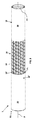
上記図面を参照すると、拡張可能ホース1が、液体を輸送するために有利に使用されている。具体的には、フレキシブルホース1は、水を輸送するための灌漑用ホースまたは水撒き用ホースであってもよい。
With reference to the above drawings, the
図3および図4で具体的に示されているように、拡張可能ホース1はポリマー内側層10およびポリマー外側層20を含んでもよい。
As specifically shown in FIGS. 3 and 4, the
拡張可能なフレキシブルホース1は、トリコットタイプの鎖編による繊維素材編物層30をさらに含んでもよい。
The expandable
上記の構造によるフレキシブルホース1が後述されるが、本発明に従ったホースは、添付の請求項によって決定される仕様に従った他の層を含んでもよいことは理解されるであろう。
Although the
例えば、二重の繊維素材補強層や、または上記層の内側または外側に1または複数の追加のポリマー層が備わっていてもよい。 For example, a double fibrous material reinforcing layer or one or more additional polymer layers may be provided inside or outside the layer.
上記の構造によるフレキシブルホース1が後述されるが、ここに説明されている技術的特徴が、添付の請求項によって決定される仕様に従った、少なくとも3層を含むホースに適用されることはさらに理解されるであろう。
Although the
水を輸送するための水撒き用ホースが以下で参照されるが、拡張可能なフレキシブルホース1は、添付の請求項によって決定される仕様に従って、いかなる目的を有してもよいし、いかなる液体を輸送してもよい。
Sprinkling hoses for transporting water are referred to below, but the expandable
好適ではあるが排他的ではない実施形態において、内側層10および外側層20は、ポリプロピレン(PP)に基づく母材を有するスチレン系熱可塑性エラストマー(TPE−S)で構成されてもよく、例えば、ASTM D2240(3”)に従って測定された、40ショアA硬度を有するNilflex(登録商標)SH(タロ プラスト エス.ピー.アー)であってもよい。このような材料は、ASTM D412/Cに従って測定された約6.5MPaの引張強度、および、ASTM D412/Cに従って測定された約880%の破断点伸び率を有している。
In a preferred but non-exclusive embodiment, the
具体的には、内側層10は1.5mmから2.5mmの厚さを有することができ、好適には1.6mmから2mmの厚さを有することができる。
Specifically, the
好適ではあるが排他的ではない実施形態において、繊維素材補強層30はポリエステル(PET)系糸で構成されてもよく、例えば、550dtexの線密度を有するBrilen GLE(登録商標)(ブライアン テック エス.アー.製)であってもよい。このような糸は、BISFA(7章)に従って測定された42.7+/−4.2Nの最大引張強度、BISFA(7章)に従って測定された12.5+/−2.5%の破断点伸び率、およびBISFA(7章)に従って測定された75.5+/−7cN/texの靱性を有している。
In a preferred but non-exclusive embodiment, the fibrous
第1の繊維素材補強層30は内側層10の外面12上に、当該外面上に複数の開放領域13(open area)を残すように配置されることができる。当該複数の開放領域13は、外側層20の内面21の対応する部分13’に直接面している。
The first fiber
内側層10と外側層20とは、非被覆領域13、13’の各々と一致して相互に固着されることができる。
The
内側層10と外側層20の間の固着は、互いに親和性を有する材料を利用して、または内側層と外側層の間に介在する粘着性材料による層によって確保されてもよい。
Adhesion between the
このような結合を有効にするために、内側層10および外側層20は一体的管状部材50を形成し、この内部で繊維素材補強層30が一体化または埋め込まれていてもよい。
In order to enable such a bond, the
ホースの全ポリマー層に、考えうる同一材料を選択することで、一体的管状部材50の機械的挙動を均一にし、材料間の最大限の親和性を確保する。
By selecting the same possible material for all polymer layers of the hose, the mechanical behavior of the
図1および2に具体的に示されているように、ホース1の端部51、52に適切な相互結合要素を備えてもよい。
As specifically shown in FIGS. 1 and 2, the ends 51, 52 of the
例えば、各々の結合器60、61を備えてもよい。
For example, the
好適ではあるが排他的ではない実施形態において、結合器60は例えばメス結合器であってもよく、ホース1を、例えば蛇口Rなどの使用場所に連結するように構成されてもよい。一方で、結合器61はオス結合器であってもよく、例えばランスまたはスプリンクラーのような、1または複数のスプリンクラー付属品Dにホース1を連結するように構成されてもよい。
In a preferred but non-exclusive embodiment, the
別の実施形態では、ホース1の端部52は、例えばランスまたはスプリンクラーのような、スプリンクラー付属品Dに強固に結合されてもよい。この場合、ホース1は結合器61を含んでおらず、それ以上のスプリンクラー付属品に結合することはできない。もう片方の端部51で、ホース1を、例えば蛇口Rなどの使用場所に連結するために、結合器60が備わっていてもよい。
In another embodiment, the
上記の特徴の結果、拡張可能なホース1は、ホース1の内部で流れる水によって付加される作動圧力によって、自動的に拡張し、および場合によっては伸張し、結果としてその元の直径、および場合によってはその元の長さを増加させることを許容することができる。
As a result of the above features, the
上記を実現するために、それ自体が公知の方法で、ホース内部の、またはホースと結合された少なくとも1つの規制部を備えることができる。 To achieve the above, at least one regulator inside the hose or coupled to the hose can be provided in a manner known per se.
好適ではあるが排他的ではない実施形態において、それ自体が公知の方法で、少なくとも1つの規制部が、結合器61内に配置された流量制限器によって規定されることができる。
In a preferred but non-exclusive embodiment, at least one regulator can be defined by a flow limiter located within the
一方で、ホース1は、例えば肥厚部など、一または複数の規制部を内部に含むことができる。
On the other hand, the
少なくとも1つの規制部は、例えばランス(lance)またはスプリンクラーのようなスプリンクラー付属品Dを備えていてもよい。 At least one regulatory unit may include a sprinkler accessory D, such as a lance or sprinkler.
少なくとも1つの規制部は、規制部の上流の圧力がホース1の内部に作用し、それによりホース1を軸Xに対して直角な半径方向に拡張し、場合によっては同じ軸Xに沿ってホース1を軸方向に伸張するような、圧力損失(pressure drop)を生じさせることができる。
In at least one regulator, pressure upstream of the regulator acts inside the
実際には、ホース1が例えば蛇口Rなどの使用場所に結合されると、蛇口を開いたときに、ホース1を流れる水が、図1および図2に示されているように、ホース1の半径方向の拡張、および場合によっては軸方向の伸長を促進する。いずれの場合も、伸張は極めて小さく、拡張と比べて顕著に小さい。
In practice, when the
言い換えると、水流は、水がその中を流れていない時のホース1と同一の元の直径D0(図3)から、作動時の直径D1(図4)へと、ホース1の移行を促進する。
In other words, the water stream facilitates the transition of
元の直径D0から作動時の直径D1への移行は徐々に行われる。 The transition from the original diameter D0 to the operating diameter D1 is gradual.
対照的に、蛇口Rを閉めると、ホース1は自動的に収縮し、よって元の直径および場合によっては元の長さに回復する。
In contrast, when the faucet R is closed, the
上記を達成するために、一体的管状部材50および繊維素材層30は互いに協働することが可能である。
To achieve the above, the
より正確には、一体的管状部材50は、例えば、水によって付加される作動圧力下で自動的に半径方向に拡張し、例えば作動圧力が停止すると、自動的に収縮するような弾性を有することができる。
More precisely, the
一方で一体的管状部材50の拡張は、図3の、水がホースを流れていないときの休止形態から、図4の、作動圧力下にあるときの作動形態へと、繊維素材補強層30の移行を促進する。
On the other hand, the expansion of the
反対に、作動圧力が停止したときに、一体的管状部材50の自動収縮が、繊維素材補強層30をその休止形態に戻す。
On the contrary, when the working pressure is stopped, the automatic contraction of the
作動圧力下で、ホースの直径の増加および場合によっては長さの増加に加え、ホースの全体的な厚さの菲薄化がさらに発生する。上記の構造および材料により、圧力下で壁厚さは約半分に減少する。 Under working pressure, in addition to increasing the diameter and possibly length of the hose, further thinning of the overall thickness of the hose occurs. Due to the above structure and materials, the wall thickness is reduced by about half under pressure.
繊維素材補強層30は、一体的管状部材50が拡張したときに、最大径を決定するために一体的管状部材50を捕捉するように適切に構成することができる。
The fibrous
上記を実施するために、繊維素材補強層30の糸および一体的管状部材50の材料は、例えば上記のように適切に選択されてもよい。
To carry out the above, the thread of the fiber
編物である繊維素材補強層30は、図3および4に示されるトリコットタイプの鎖編でもよく、または、同一出願人名義の欧州特許第0623776号の教示に従って製造されてもよい。
The fiber
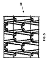
その代わりに、編物である繊維素材補強層30は図5に示されるダイヤモンド編タイプであってもよく、または、同一出願人名義の欧州特許第0527512号によって教示される放射状タイプでもよい。
Alternatively, the knitted fiber
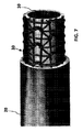
別の実施形態では、編物である繊維素材補強層30は図6に示される両面編タイプであってもよく、または、図7に示される編込みタイプであってもよい。
In another embodiment, the knitted fiber
編物構造の代わりに、第1の繊維素材補強層30は織物または結節によるものであってもよい。図8および9は織物である繊維素材補強層の2つの例を示しており、糸の向き、数および構成がそれぞれ異なる。図10は結節である繊維補強層の例を示している。
Instead of the knitted structure, the first fibrous
2バール(2bar、2×10⁵Pa)の作動圧力下で、ホースは、その外径を元の外径の少なくとも1.3倍、好適には元の径の少なくとも1.4倍、より好適には元の径の少なくとも1.45倍、さらに好適には元の径の少なくとも1.5倍に拡張するように、一体的管状部材および少なくとも1つの繊維素材補強層は互いに協働してもよい。 2 bar (2bar, 2 × 10 5 Pa ) under operating pressure of the hose is at least 1.3 times the original external diameter of the outer diameter, preferably at least 1.4 times the original size, more preferably The integral tubular member and at least one fibrous material reinforcing layer may cooperate with each other so as to extend at least 1.45 times the original diameter, and more preferably at least 1.5 times the original diameter. Good.
例えば、上記のような構造を有し、上記の材料で製造された、休止時に9mmの内径、休止時に14.5mmの外径、および80g/mt(メートル当たり重量)の重量を備えたホースを用いた場合、異なる内部作動圧力での拡張は、以下の表1のように発生する。 For example, a hose having the above structure and made of the above materials and having an inner diameter of 9 mm at rest, an outer diameter of 14.5 mm at rest, and a weight of 80 g / mt (weight per meter). When used, expansion at different internal working pressures occurs as shown in Table 1 below.

これらのデータが、材料および/もしくはホースの内径または外径または重量/mtなどのホースの特徴に応じて変化しうることは理解されるであろう。 It will be appreciated that these data may vary depending on the characteristics of the hose, such as material and / or hose inner or outer diameter or weight / mt.
5バール(5bar、5×10⁵Pa)の作動圧力下で、一体的管状部材50の長さ方向の伸張が、元の長さに対して20%未満、好適には元の長さに対して15%未満であるように、一体的管状部材50および繊維素材補強層30が互いに協働することができる。
Under working pressure of 5 bar (5 bar, 5 × 10 5 Pa), the extension of the
この膜20は、下部層、特に繊維素材層を保護することを目的としており、さらに、ホースに外観を持たせる役割を果たしている。また、外部からの化学物質への抵抗や、地表でのホースの滑りに関しても重要である。実際、この膜はぬかるんだ地面や庭での使用によるホースの付着物を最小限に抑える。
The
上記の説明から、本発明は、意図する目的を達成することは明らかである。 From the above description, it is clear that the present invention achieves the intended object.
本発明は様々な修正および変更を受け入れる余地があり、それらはすべて、添付する請求項で示された発明概念に該当する。すべての詳細事項は本発明の請求範囲から逸脱することなく、他の技術的等価要素と置き換えられてもよく、材料は要件に応じて異なるものであってもよい。 The present invention has room for various modifications and modifications, all of which fall under the concept of the invention set forth in the appended claims. All details may be replaced with other technical equivalents without departing from the claims of the invention, and the materials may vary according to requirements.
本発明は添付図面を具体的に参照して説明されているが、詳細な説明および請求項の中で使用されている参照符号は本発明の情報をより分かりやすくさせるために使用されており、本発明の請求範囲を限定するものではない。 Although the present invention is described specifically with reference to the accompanying drawings, the reference numerals used in the detailed description and claims are used to make the information of the present invention more understandable. The claims of the present invention are not limited.
Claims (10)
− 第1の弾性ポリマー材料で作られた少なくとも1つの内側層(10)と、
− 第2の弾性ポリマー材料で作られた少なくとも1つの外側層(20)と、
− 前記少なくとも1つの内側層(10)と前記少なくとも1つの外側層(20)の間に介在する少なくとも1つの繊維素材補強層(30)と、を含み、
前記少なくとも1つの内側層(10)および前記少なくとも1つの外側層(20)は、一体的管状部材(50)を形成するように相互に結合し、前記少なくとも1つの繊維素材補強層(30)は前記一体的管状部材(50)に埋め込まれており、
前記一体的管状部材(50)は、前記一体的管状部材(50)を通って流れる液体によって付加される前記作動圧力下で自動的に拡張して、その元の外径を増加させ、および、再度前記元の外径となるために、前記作動圧力が停止すると自動的に回復するような弾性を有し、
前記少なくとも1つの繊維素材補強層(30)が、液体が前記一体的管状部材(50)を通って流れていないときの休止形態と、前記一体的管状部材(50)が前記作動圧力によって拡張するときの作動形態の間での動作を許容し、
2バールの作動圧力下で、前記ホースが外径を元の外径に対して少なくとも1.3倍に拡張するように、前記一体的管状部材(50)と前記少なくとも1つの繊維素材補強層(30)とが互いに協働することを特徴とするホース。 An expandable flexible hose that transports liquids, especially water,
-At least one inner layer (10) made of the first elastic polymer material,
-With at least one outer layer (20) made of a second elastic polymer material,
− Containing at least one fibrous material reinforcing layer (30) interposed between the at least one inner layer (10) and the at least one outer layer (20).
The at least one inner layer (10) and the at least one outer layer (20) are coupled to each other to form an integral tubular member (50), and the at least one fibrous material reinforcing layer (30) is It is embedded in the integral tubular member (50) and
The integral tubular member (50) automatically expands under the working pressure applied by the liquid flowing through the integral tubular member (50) to increase its original outer diameter, and. Since it returns to the original outer diameter again, it has elasticity that automatically recovers when the operating pressure stops.
The at least one fiber material reinforcing layer (30) is in a dormant form when the liquid is not flowing through the integral tubular member (50), and the integral tubular member (50) is expanded by the operating pressure. Allows movement between modes of operation when
The integral tubular member (50) and the at least one fibrous material reinforcing layer (so that the hose expands its outer diameter by at least 1.3 times its original outer diameter under operating pressure of 2 bar). A hose characterized in that 30) and the hose cooperate with each other.
− 請求項1から9のいずれか一項に記載の拡張可能なフレキシブルホースと、− The expandable flexible hose according to any one of claims 1 to 9.
− 前記ホースの拡張を促進する作動圧力を前記ホース内に生成するための、少なくとも1つの規制部すなわち少なくとも1つの流量制限器(61)であって、前記ホース内部に配置されるか又は前記ホースに連結されている、前記少なくとも1つの規制部すなわち少なくとも1つの流量制限器(61)と、-At least one regulator, i.e. at least one flow limiter (61), for generating working pressure in the hose that facilitates expansion of the hose, either located inside the hose or the hose. The at least one regulator, i.e. at least one flow limiter (61), which is connected to the
を備えていることを特徴とするホース組立体。A hose assembly characterized by being equipped with.
Applications Claiming Priority (1)
| Application Number | Priority Date | Filing Date | Title |
|---|---|---|---|
| PCT/IB2016/052435 WO2017187233A1 (en) | 2016-04-29 | 2016-04-29 | Enlargeable flexible hose |
Publications (3)
| Publication Number | Publication Date |
|---|---|
| JP2019515200A JP2019515200A (en) | 2019-06-06 |
| JP2019515200A5 JP2019515200A5 (en) | 2019-07-11 |
| JP6845872B2 true JP6845872B2 (en) | 2021-03-24 |
Family
ID=56069176
Family Applications (1)
| Application Number | Title | Priority Date | Filing Date |
|---|---|---|---|
| JP2018554569A Active JP6845872B2 (en) | 2016-04-29 | 2016-04-29 | Expandable flexible hose |
Country Status (6)
| Country | Link |
|---|---|
| US (2) | US10927983B2 (en) |
| EP (1) | EP3449162B1 (en) |
| JP (1) | JP6845872B2 (en) |
| AU (2) | AU2016404620A1 (en) |
| CA (1) | CA3021751C (en) |
| WO (1) | WO2017187233A1 (en) |
Families Citing this family (11)
| Publication number | Priority date | Publication date | Assignee | Title |
|---|---|---|---|---|
| CA3021751C (en) * | 2016-04-29 | 2023-06-20 | Fitt S.P.A. | Enlargeable flexible hose |
| CN110114605B (en) * | 2016-10-28 | 2022-02-01 | 阿德加一人股份责任有限公司 | Telescopic corrugated hose and preparation method thereof |
| FR3069611B1 (en) | 2017-07-31 | 2020-03-06 | Exel Industries | LAYER AND PIPE COMPRISING SUCH A LAYER |
| US11022238B2 (en) * | 2018-04-27 | 2021-06-01 | Fiskars Finland Oy Ab | Lightweight hose |
| BR202018067754U2 (en) * | 2018-09-04 | 2020-03-17 | Eduardo Feital De Carlo | FIRE HOSE WITH REFLECTIVE BALLIZER |
| DE102019107481A1 (en) * | 2019-03-22 | 2020-09-24 | Yuan Pin Industrial Co., Ltd. | Extensible water hose |
| CN110260060A (en) * | 2019-07-26 | 2019-09-20 | 浙江海伦塑胶有限公司 | Flexible water pipe |
| CN110553103A (en) * | 2019-08-26 | 2019-12-10 | 阳江市新特体育科技用品有限公司 | novel telescopic water pipe and manufacturing method thereof |
| IT201900021978A1 (en) * | 2019-11-22 | 2021-05-22 | Fitt Spa | FLAT FLEXIBLE HOSE MADE OF THERMOPLASTIC ELASTOMER FOR THE TRANSPORT OF FLUIDS |
| US11927284B2 (en) * | 2020-06-24 | 2024-03-12 | Winston Products Llc | Expandable hose |
| US12066129B2 (en) * | 2022-10-20 | 2024-08-20 | Qmax, Llc | Tubes and methods of expanding and/or contracting tubes |
Family Cites Families (65)
| Publication number | Priority date | Publication date | Assignee | Title |
|---|---|---|---|---|
| DE569929C (en) | 1933-02-09 | Kuebler & Co M B H E | Rubber hose with helical folds with fabric wraps | |
| US3028290A (en) | 1959-02-10 | 1962-04-03 | Fred T Roberts | Method and apparatus for forming a reinforced corrugated hose |
| BE754793A (en) | 1969-08-14 | 1971-02-15 | America Esna Corp | IMPROVEMENTS IN (OR RELATING TO) FLEXIBLE PIPING |
| US3682202A (en) * | 1970-01-22 | 1972-08-08 | Goodyear Tire & Rubber | Reinforced hose |
| US3934064A (en) * | 1971-11-24 | 1976-01-20 | E. I. Du Pont De Nemours And Company | Composite structures of knitted glass fabric and thermoplastic polyfluoroethylene resin sheet |
| JPS5329206Y2 (en) | 1973-11-07 | 1978-07-22 | ||
| US4009734A (en) | 1976-02-26 | 1977-03-01 | Parker-Hannifin Corporation | Coiled tubing |
| FR2468826A1 (en) | 1979-10-31 | 1981-05-08 | Capri Codec Sa | Pipe couplings with conic seals backed by an annular spring - to compensate for elastic fatigue by thermal cycling |
| DE3018417A1 (en) | 1980-05-14 | 1981-11-19 | Hans Grohe Gmbh & Co Kg, 7622 Schiltach | FLEXIBLE DOUBLE-WALLED PRESSURE HOSE, IN PARTICULAR SHOWER HOSE, AND METHOD FOR THE PRODUCTION THEREOF |
| DE3304079C1 (en) | 1983-02-07 | 1984-07-12 | Vohrer, Christoph, 6240 Königstein | Hose for the production of hose ends having predetermined lengths, and method for producing the hose |
| EP0151017A3 (en) | 1984-01-30 | 1986-05-14 | The Gates Rubber Company | Hose stem with locking collar and method |
| US4923226A (en) | 1987-06-23 | 1990-05-08 | Proprietary Technology, Inc. | Apparatus for attaching a hose to a fitting |
| US4957792A (en) | 1987-11-09 | 1990-09-18 | Toyo Tire & Rubber Co., Ltd. | Self-molding hose and a continuous vulcanization method |
| US4989643A (en) * | 1988-12-20 | 1991-02-05 | Chase-Walton Elastomers, Inc. | High performance composite hose |
| JPH03157599A (en) | 1989-11-16 | 1991-07-05 | Toyoda Mach Works Ltd | Pressure fluid supply hose |
| IT1253759B (en) | 1991-08-07 | 1995-08-23 | Fitt Spa | FLEXIBLE HOSE WITH REINFORCING LINK |
| IT1270777B (en) * | 1993-05-13 | 1997-05-07 | Fitt Spa | FLEXIBLE HOSE WITH CHAIN LINK |
| DE19524394C1 (en) | 1995-07-04 | 1997-01-09 | Tecalemit Gmbh Deutsche | Expansion hose |
| US5816622A (en) * | 1996-04-30 | 1998-10-06 | Teknor Apex Company | Protective sleeve for garden hose |
| US20010010339A1 (en) | 1997-09-09 | 2001-08-02 | Thomas Jeffrey A. | Coiled hose and spray nozzle |
| WO1999015326A1 (en) | 1997-09-19 | 1999-04-01 | Total Containment, Inc. | Improved flexible hose construction and method of making same |
| FR2784447B1 (en) | 1998-10-08 | 2000-12-22 | Fed Mogul Systems Prot Group | TEXTILE SHEATH FOR RUBBER TUBE |
| US6561550B1 (en) | 2000-10-16 | 2003-05-13 | Alfmeier Prazision Ag Baugruppen Und Systemlosungen | Hose connection |
| US6227579B1 (en) | 1999-11-30 | 2001-05-08 | Lakeshore Automatic Products Inc. | Swivel garden hose connector |
| CN2435609Y (en) | 2000-08-16 | 2001-06-20 | 邓全龙 | Flexible water-sucking hose for fire vehicle |
| AU2002338619A1 (en) | 2001-04-09 | 2002-10-28 | Quarterlock, Inc. | Hose coupling device |
| US6948527B2 (en) | 2001-11-24 | 2005-09-27 | Gary Dean Ragner | Pressure-actuated linearly retractable and extendible hose |
| US8776836B2 (en) | 2001-11-24 | 2014-07-15 | Ragner Technology Corporation | Linearly retractable pressure hose structure |
| JP4619329B2 (en) | 2005-08-09 | 2011-01-26 | 芦森工業株式会社 | Structure of connection between hose and fitting |
| DE102008022663B4 (en) | 2008-05-07 | 2012-10-31 | Schauenburg Hose Technology Gmbh | Stretch hose |
| ITVI20080260A1 (en) * | 2008-11-04 | 2010-05-05 | Fitt Spa | FLEXIBLE HOSE FOR MULTILAYER IRRIGATION |
| ITVI20090013U1 (en) | 2009-03-25 | 2010-09-26 | Fitt Spa | FLEXIBLE HOSE WITH DECORATIVE ELEMENTS |
| US20120042980A1 (en) * | 2009-05-12 | 2012-02-23 | Fitt S.P.A. | Reinforced Flexible Hose with High Pressure Strength and Method for its Manufacturing |
| ITVI20100217A1 (en) * | 2010-07-30 | 2012-01-31 | Fitt Spa | STRUCTURE OF FLEXIBLE HOSE WITH INTERLACED REINFORCEMENT |
| WO2012109249A2 (en) | 2011-02-07 | 2012-08-16 | Saint-Gobain Performance Plastics Corporation | A flexible article and method of forming the article |
| US8479776B2 (en) * | 2011-11-04 | 2013-07-09 | Blue Gentian, Llc | Expandable garden hose |
| US8757213B2 (en) | 2011-11-04 | 2014-06-24 | Blue Gentian, Llc | Commercial hose |
| US8291942B2 (en) | 2011-11-04 | 2012-10-23 | Blue Gentian, Llc | Expandable hose assembly |
| US8291941B1 (en) | 2011-11-04 | 2012-10-23 | Blue Gentian, Llc | Expandable and contractible hose |
| NL2008092C2 (en) | 2012-01-10 | 2013-07-15 | Lankhorst Mouldings B V | BENDING RESTRICTION ELEMENT FOR LIMITING THE BENDING RANGE OF A PIPE. |
| CA2870793C (en) | 2012-04-18 | 2017-07-11 | Roger C. Walsh | Self-draining hose |
| US8936046B2 (en) * | 2012-11-09 | 2015-01-20 | Ragner Technology Corporation | Elastic and spring biased retractable hoses |
| US9127791B2 (en) | 2012-11-09 | 2015-09-08 | Ragner Technology Corporation | Lubricated elastically biased stretch hoses |
| US9182057B2 (en) | 2013-08-10 | 2015-11-10 | Ragner Technology Corporation | Retractable elastic bungee hose |
| EP2764992B1 (en) | 2013-02-08 | 2020-06-17 | ContiTech MGW GmbH | Flexible hose |
| EP2628988A1 (en) | 2013-03-13 | 2013-08-21 | Actervis Gmbh | Water hose |
| DE202013101116U1 (en) | 2013-03-15 | 2013-03-25 | Newbud Industrial Corp. | Telescopic water pipe |
| JP6381181B2 (en) | 2013-07-03 | 2018-08-29 | ホーチキ株式会社 | Fire hose |
| US9844921B2 (en) * | 2013-08-10 | 2017-12-19 | Ragner Technology Corporation | Annular-pleated circular braid |
| TWM469410U (en) | 2013-08-20 | 2014-01-01 | Huang-Fu Huang | Tube expansion apparatus |
| TWM469409U (en) | 2013-08-23 | 2014-01-01 | Ming-Yan Wu | Expandable tube structure improvement |
| US9074711B2 (en) * | 2013-08-28 | 2015-07-07 | Huang Fu Huang | Axially expansible pipe assembly |
| CN203628131U (en) | 2013-12-10 | 2014-06-04 | 天台县富华塑胶有限公司 | Equal-proportional telescopic expansion pipe |
| CN203868543U (en) | 2014-03-18 | 2014-10-08 | 阳江市新特体育用品有限公司 | High-elasticity retractable water pipe with gradients |
| DE202014004448U1 (en) | 2014-06-02 | 2014-06-23 | Actervis Gmbh | water hose |
| CN104197141A (en) | 2014-08-21 | 2014-12-10 | 天台县富华塑胶有限公司 | Production process of equal-proportion stretching and retracting expansion tube |
| CN104405967A (en) | 2014-10-11 | 2015-03-11 | 陆宋瑞 | Elastic telescopic braided pipe and production process thereof |
| CN204267921U (en) | 2014-11-21 | 2015-04-15 | 台州市路桥正来塑胶厂 | A kind of telescopic pipe |
| US9863565B2 (en) | 2014-11-25 | 2018-01-09 | Teknor Apex Company | Multi-layer expandable hose |
| EA031710B1 (en) | 2014-12-18 | 2019-02-28 | Фитт С.П.А. | Extensible flexible hose and method for continuously manufacturing the same |
| DE202015100073U1 (en) | 2015-01-09 | 2015-02-09 | Shanghai Q Mall & Co., Ltd. | Automatically telescopic stretch water hose with extended life |
| CN107614953B (en) | 2015-04-24 | 2022-08-05 | 特诺尔艾佩斯公司 | Lightweight high flow hose assembly and method of manufacture |
| CA3021751C (en) * | 2016-04-29 | 2023-06-20 | Fitt S.P.A. | Enlargeable flexible hose |
| IT201700071472A1 (en) * | 2017-06-27 | 2018-12-27 | Fitt Spa | ULTRALIGHT REINFORCED HOSE |
| JP2019094578A (en) | 2017-11-17 | 2019-06-20 | 株式会社豊田自動織機 | Fiber structure and fiber reinforced composite material |
-
2016
- 2016-04-29 CA CA3021751A patent/CA3021751C/en active Active
- 2016-04-29 AU AU2016404620A patent/AU2016404620A1/en not_active Abandoned
- 2016-04-29 US US16/096,257 patent/US10927983B2/en active Active
- 2016-04-29 WO PCT/IB2016/052435 patent/WO2017187233A1/en active Application Filing
- 2016-04-29 EP EP16724473.0A patent/EP3449162B1/en active Active
- 2016-04-29 JP JP2018554569A patent/JP6845872B2/en active Active
-
2021
- 2021-01-16 US US17/151,145 patent/US11353143B2/en active Active
-
2023
- 2023-03-27 AU AU2023201870A patent/AU2023201870B2/en active Active
Also Published As
| Publication number | Publication date |
|---|---|
| US10927983B2 (en) | 2021-02-23 |
| US11353143B2 (en) | 2022-06-07 |
| AU2023201870A1 (en) | 2023-04-27 |
| NZ747740A (en) | 2023-08-25 |
| AU2016404620A1 (en) | 2018-11-22 |
| CA3021751A1 (en) | 2017-11-02 |
| US20190145553A1 (en) | 2019-05-16 |
| EP3449162A1 (en) | 2019-03-06 |
| US20210140568A1 (en) | 2021-05-13 |
| JP2019515200A (en) | 2019-06-06 |
| WO2017187233A1 (en) | 2017-11-02 |
| AU2023201870B2 (en) | 2024-11-28 |
| CA3021751C (en) | 2023-06-20 |
| EP3449162B1 (en) | 2021-07-21 |
Similar Documents
| Publication | Publication Date | Title |
|---|---|---|
| JP6845872B2 (en) | Expandable flexible hose | |
| US11287066B2 (en) | Extensible flexible hose, and method and production line for continuously manufacturing thereof | |
| US10981349B2 (en) | Ultra-lightweight reinforced flexible hose | |
| CN111051755B (en) | Layer and pipe comprising such a layer | |
| AU2015100607A4 (en) | Water Hose | |
| TWI680251B (en) | Extensible flexible hose | |
| NZ747740B2 (en) | Enlargeable flexible hose |
Legal Events
| Date | Code | Title | Description |
|---|---|---|---|
| A521 | Request for written amendment filed |
Free format text: JAPANESE INTERMEDIATE CODE: A821 Effective date: 20181210 |
|
| RD01 | Notification of change of attorney |
Free format text: JAPANESE INTERMEDIATE CODE: A7426 Effective date: 20181210 |
|
| A521 | Request for written amendment filed |
Free format text: JAPANESE INTERMEDIATE CODE: A523 Effective date: 20190418 |
|
| A621 | Written request for application examination |
Free format text: JAPANESE INTERMEDIATE CODE: A621 Effective date: 20190418 |
|
| A131 | Notification of reasons for refusal |
Free format text: JAPANESE INTERMEDIATE CODE: A131 Effective date: 20200519 |
|
| A521 | Request for written amendment filed |
Free format text: JAPANESE INTERMEDIATE CODE: A523 Effective date: 20200817 |
|
| TRDD | Decision of grant or rejection written | ||
| A01 | Written decision to grant a patent or to grant a registration (utility model) |
Free format text: JAPANESE INTERMEDIATE CODE: A01 Effective date: 20210202 |
|
| A61 | First payment of annual fees (during grant procedure) |
Free format text: JAPANESE INTERMEDIATE CODE: A61 Effective date: 20210226 |
|
| R150 | Certificate of patent or registration of utility model |
Ref document number: 6845872 Country of ref document: JP Free format text: JAPANESE INTERMEDIATE CODE: R150 |
|
| R250 | Receipt of annual fees |
Free format text: JAPANESE INTERMEDIATE CODE: R250 |