JP6845552B2 - box - Google Patents
box Download PDFInfo
- Publication number
- JP6845552B2 JP6845552B2 JP2016175102A JP2016175102A JP6845552B2 JP 6845552 B2 JP6845552 B2 JP 6845552B2 JP 2016175102 A JP2016175102 A JP 2016175102A JP 2016175102 A JP2016175102 A JP 2016175102A JP 6845552 B2 JP6845552 B2 JP 6845552B2
- Authority
- JP
- Japan
- Prior art keywords
- pair
- bent
- box
- positioning
- lid
- Prior art date
- Legal status (The legal status is an assumption and is not a legal conclusion. Google has not performed a legal analysis and makes no representation as to the accuracy of the status listed.)
- Expired - Fee Related
Links
- 238000005452 bending Methods 0.000 claims description 14
- 238000000034 method Methods 0.000 description 7
- 238000004519 manufacturing process Methods 0.000 description 5
- 238000007789 sealing Methods 0.000 description 4
- 239000000463 material Substances 0.000 description 3
- 238000003780 insertion Methods 0.000 description 2
- 230000037431 insertion Effects 0.000 description 2
- 241001672694 Citrus reticulata Species 0.000 description 1
- 230000015572 biosynthetic process Effects 0.000 description 1
- 238000007796 conventional method Methods 0.000 description 1
- 230000003993 interaction Effects 0.000 description 1
- 239000000123 paper Substances 0.000 description 1
Images

Landscapes
- Cartons (AREA)
Description
本発明は、内蓋を覆う外蓋で蓋部を形成する箱に関する。 The present invention relates to a box in which a lid is formed by an outer lid that covers an inner lid.
段ボールを適用した段ボール箱が知られている。段ボール箱は、箱本体から延長して形成された内蓋および内蓋を覆う外蓋を備える。従来の段ボール箱は、外蓋の折り曲げ部の弾性による外側への反りに対して種々の工夫を施している(例えば、特許文献1、特許文献2参照)。 Corrugated cardboard boxes to which corrugated cardboard is applied are known. The corrugated cardboard box includes an inner lid formed extending from the box body and an outer lid covering the inner lid. In the conventional corrugated cardboard box, various measures are taken against the outward warp due to the elasticity of the bent portion of the outer lid (see, for example, Patent Document 1 and Patent Document 2).
特許文献1に開示された発明は、内蓋に形成されたスリットに外蓋の係合片を嵌め込む形態を有する。すなわち、特許文献1の技術は、内蓋にスリットを形成し、外蓋に係合片を形成して、係合片をスリットに挿入することで外蓋の閉ロック力を確保している。
特許文献2に開示された発明は、内蓋および外蓋の内、外蓋に封緘部材を取り付ける形態を有する。すなわち、特許文献2の技術は、封緘部材という本体とは別の部材を新たに取り付けることによって、外蓋を適宜に開け閉めできる形態としている。
The invention disclosed in Patent Document 1 has a form in which an engaging piece of an outer lid is fitted into a slit formed in the inner lid. That is, in the technique of Patent Document 1, a slit is formed in the inner lid, an engaging piece is formed in the outer lid, and the engaging piece is inserted into the slit to secure the closing locking force of the outer lid.
The invention disclosed in Patent Document 2 has a form in which a sealing member is attached to the inner lid, the inner lid, and the outer lid. That is, the technique of Patent Document 2 has a form in which the outer lid can be appropriately opened and closed by newly attaching a member other than the main body, which is a sealing member.
しかし、特許文献1に記載された技術は、閉ロック力を実現するために、スリットおよび係合片を形成する工程が必要であること、係合片をスリットに挿入する工程が必要であることなど製造過程の増加に伴う工程の複雑さをもたらしている。また、特許文献2に記載された技術は、外蓋をロックして固定するために別部材としての封緘部材を準備する必要がある。また、封緘部材を取り付ける新たな工程が必要になる。
さらに、これらの従来技術では、外蓋を閉じたときに外蓋の平坦性を確保できないなどの課題が生じていた。本発明はこのような状況に鑑みてなされたものであり、外蓋を閉じたときの外蓋の平坦性を簡潔な構造で容易に実現しやすい箱を提供することを目的とする。
However, the technique described in Patent Document 1 requires a step of forming a slit and an engaging piece and a step of inserting the engaging piece into the slit in order to realize a closing locking force. It brings about the complexity of the process due to the increase of the manufacturing process. Further, in the technique described in Patent Document 2, it is necessary to prepare a sealing member as a separate member in order to lock and fix the outer lid. In addition, a new process for attaching the sealing member is required.
Further, in these conventional techniques, there has been a problem that the flatness of the outer lid cannot be ensured when the outer lid is closed. The present invention has been made in view of such a situation, and an object of the present invention is to provide a box in which the flatness of the outer lid when the outer lid is closed can be easily realized with a simple structure.
本発明に係る箱は、直方体の天面に位置する蓋部を有する箱であって、相互に対向する一対の第1辺、および前記第1辺に隣接して相互に対向する一対の第2辺を有する底面と、一対の前記第1辺から立ち上がって相互に向き合う一対の第1側面と、一対の前記第2辺から立ち上がって相互に向き合い前記第1側面にそれぞれ隣接する一対の第2側面と、一対の前記第1側面からそれぞれ延長し、前記第1側面の上端の第1折り曲げ部でそれぞれ折り曲げられて前記底面に対向する一対の内蓋と、一対の前記第2側面からそれぞれ延長し、前記第2側面の上端の第2折り曲げ部でそれぞれ折り曲げられ、前記内蓋を覆って前記蓋部を形成する一対の外蓋と、を備え、一対の前記外蓋のそれぞれは、先端に、前記第2折り曲げ部と平行な第3折り曲げ部で折り曲げられて前記内蓋の下側へ嵌め込まれる一対の嵌め込み部を有し、一対の前記内蓋のそれぞれは、前記第1折り曲げ部の中心から前記内蓋が有する先端部の中心までを対称軸として切断された一対の分割内蓋を有し、一対の前記分割内蓋は、前記対称軸に沿ってそれぞれ対称に、前記第1折り曲げ部の側に、前記嵌め込み部が嵌め込まれるとき内側に曲げられて相互に摩擦力を生じる摩擦部と、前記先端部の側に、前記嵌め込み部を整合的に位置決めする位置決め部と、を有し、前記摩擦部は、前記第1折り曲げ部に沿って前記対称軸に対して対称に形成された切断部によって前記第1折り曲げ部から分離されていることを特徴とする。 The box according to the present invention is a box having a lid portion located on the top surface of a rectangular body, and has a pair of first sides facing each other and a pair of second sides adjacent to the first side and facing each other. A bottom surface having sides, a pair of first side surfaces that stand up from the pair of the first sides and face each other, and a pair of second side surfaces that stand up from the pair of the second sides and face each other and are adjacent to each other. And each of the pair of inner lids that extend from the first side surface and are bent at the first bent portion at the upper end of the first side surface to face the bottom surface and extend from the pair of the second side surfaces. A pair of outer lids, each of which is bent at a second bent portion at the upper end of the second side surface to cover the inner lid to form the lid portion, are provided, and each of the pair of outer lids has a tip. It has a pair of fitting portions that are bent at a third bending portion parallel to the second bending portion and fitted to the lower side of the inner lid, and each of the pair of the inner lids is from the center of the first bending portion. It has a pair of divided inner lids cut up to the center of the tip portion of the inner lid as an axis of symmetry, and the pair of the divided inner lids are symmetrical along the axis of symmetry of the first bent portion. on the side, a friction portion causing frictional forces to each other are bent inwardly when the fitting portion is fitted, on the side of the tip, have a, a positioning portion for positioning said fitting portion Consistently, the friction unit is characterized that you have been separated from the first bent portion by the cutting portion formed symmetrically with respect to the symmetry axis along the first folding portion.
この構成により、本発明に係る箱は、外蓋が第2折り曲げ部で生じる弾性による反りを抑制する。つまり、分割内蓋が有する摩擦部の弾性で嵌め込み部の両端を加圧して保持するので、第2折り曲げ部における反りを抑制し、位置決め部で嵌め込み部の両端を除く中央領域を内蓋に嵌め込んだ状態を維持する。
本発明に係る箱は、内蓋と外蓋の形状を少し変えただけの簡潔な構造で蓋部(外蓋)の平坦性を容易に実現しやすくする。このような作用効果は箱を段ボールで形成して段ボール箱とした場合に特に有効となる。つまり、外蓋は他の部材を用いずに閉じたときの平坦性を容易に実現しやすくなる。このため、一対の外蓋に対してテープなどを張り付けて平坦性を確保する必要性が抑制される。
With this configuration, in the box according to the present invention, the outer lid suppresses warpage due to elasticity generated at the second bent portion. That is, since both ends of the fitting portion are pressed and held by the elasticity of the friction portion of the split inner lid, warpage at the second bent portion is suppressed, and the central region excluding both ends of the fitting portion is fitted to the inner lid at the positioning portion. Keep it crowded.
The box according to the present invention has a simple structure in which the shapes of the inner lid and the outer lid are slightly changed, so that the flatness of the lid portion (outer lid) can be easily realized. Such an action effect is particularly effective when the box is made of corrugated cardboard to form a corrugated cardboard box. That is, the outer lid can easily achieve flatness when closed without using other members. Therefore, the need to attach a tape or the like to the pair of outer lids to ensure flatness is suppressed.
また、本発明の一実施態様に係る箱では、前記切断部は、一対の前記位置決め部の間の間隔で定まる位置決め幅と同じ寸法で切断されていることを特徴とする。
また、本発明の一実施態様に係る箱では、前記位置決め幅は、一対の前記嵌め込み部が互いに重ねられて前記位置決め部に嵌め込まれるときの厚みと略等しいことを特徴とする。
また、本発明の一実施態様に係る箱では、前記摩擦部は、前記第2折り曲げ部に沿う方向で略30mmの摩擦長を有することを特徴とする。
また、本発明の一実施態様に係る箱では、前記直方体は、段ボールで形成されていることを特徴とする。
Also, in the box according to an embodiment of the present invention, the cutting unit is characterized in that it is cut with the same dimensions as the positioning width determined by the spacing between the pair of the positioning unit.
Further, in the box according to the embodiment of the present invention, the positioning width is substantially equal to the thickness when the pair of the fitting portions are overlapped with each other and fitted into the positioning portion.
Further, in the box according to the embodiment of the present invention, the friction portion has a friction length of about 30 mm in the direction along the second bent portion.
Further, in the box according to the embodiment of the present invention, the rectangular parallelepiped is made of corrugated cardboard.
本発明に係る箱は、内蓋と外蓋の形状を少し変えただけの簡潔な構造で蓋部(外蓋)の平坦性を容易に実現しやすくする。このような作用効果は箱を段ボールで形成して段ボール箱とした場合に特に有効となる。つまり、外蓋は他の部材を用いずに閉じたときの平坦性を容易に実現しやすくなる。このため、一対の外蓋に対してテープなどを張り付けて平坦性を確保する必要性が抑制されるという効果を奏する。 The box according to the present invention has a simple structure in which the shapes of the inner lid and the outer lid are slightly changed, so that the flatness of the lid portion (outer lid) can be easily realized. Such an action effect is particularly effective when the box is made of corrugated cardboard to form a corrugated cardboard box. That is, the outer lid can easily achieve flatness when closed without using other members. Therefore, it is possible to suppress the need to attach a tape or the like to the pair of outer lids to ensure flatness.
以下、本発明の実施の形態について図面を参照して説明する。
図1から図4までを参照して、本実施の形態に係る箱1(段ボール箱10)について説明する。
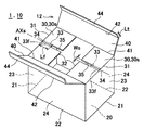
図1は、本発明の実施の形態1に係る箱1の内蓋30を閉じ、外蓋40を閉める前の状態を斜め上方から見て示す斜視図である。
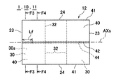
図2は、図1に示した箱の外蓋40を閉じた状態を平面視で示す平面図である。
Hereinafter, embodiments of the present invention will be described with reference to the drawings.
The box 1 (cardboard box 10) according to the present embodiment will be described with reference to FIGS. 1 to 4.
FIG. 1 is a perspective view showing a state before the
FIG. 2 is a plan view showing a state in which the
直方体11の天面に位置する蓋部12を有する箱1は、相互に対向する一対の第1辺21、および第1辺21に隣接して相互に対向する一対の第2辺22を有する底面20と、一対の第1辺21から立ち上がって相互に向き合う一対の第1側面23と、一対の第2辺22から立ち上がって相互に向き合い第1側面23にそれぞれ隣接する一対の第2側面24と、を備える。
箱1は、一対の第1側面23からそれぞれ延長し、第1側面23の上端の第1折り曲げ部31でそれぞれ折り曲げられて底面20に対向する一対の内蓋30と、一対の第2側面24からそれぞれ延長し、第2側面24の上端の第2折り曲げ部41でそれぞれ折り曲げられ、内蓋30を覆って蓋部12を形成する一対の外蓋40と、を備える。
The box 1 having the
The box 1 extends from the pair of
一対の外蓋40のそれぞれは、先端に、第2折り曲げ部41と平行な第3折り曲げ部42で折り曲げられて内蓋30の下側へ嵌め込まれる一対の嵌め込み部44を有し、一対の内蓋30のそれぞれは、第1折り曲げ部31の中心から内蓋30が有する先端部32の中心までを対称軸AXsとして切断された一対の分割内蓋30sを有する。
一対の分割内蓋30sは、対称軸AXsに沿ってそれぞれ対称に、第1折り曲げ部31の側に、嵌め込み部44が嵌め込まれるとき内側に曲げられて相互に摩擦力を生じる摩擦部33と、先端部32の側に、嵌め込み部44を整合的に位置決めする位置決め部35と、を有する。
Each of the pair of
The pair of divided
箱1は、一対の嵌め込み部44を重ね合わせて一体化し、一体化した状態の嵌め込み部44を一対の摩擦部33に位置合わせして外力によって摩擦部33を内側へ押し込むので、一対の外蓋40を閉じたとき、摩擦部33は、底面20の方へ曲げられる。
なお、一対の嵌め込み部44は、それぞれ個別に摩擦部33へ押し込まれても良い。段ボールなどの素材の状態に応じて押込みが円滑に施せる形態(一方毎、あるいは一対を一括)で押し込むことが好ましい。
曲げられた摩擦部33は弾性によって外蓋40の側へ反る性質を有しているから、嵌め込み部44との間で相互に摩擦力が作用する。したがって、分割内蓋30sに対して底面20の側へ嵌め込まれた嵌め込み部44は、摩擦部33によって固定した状態を維持する。
また、位置決め部35に向き合う範囲の嵌め込み部44は、位置決め部35にそのまま嵌め込まれる。したがって、位置決め部35に嵌め込まれた嵌め込み部44は、嵌め込み部44が外力で曲げた摩擦部33で生じる摩擦力によって両側を保持された状態を維持する。
箱1は、外蓋40が第2折り曲げ部41で生じる弾性による反りを抑制する。つまり、分割内蓋30sが有する摩擦部33の弾性で嵌め込み部44の両端を加圧して保持するので、第2折り曲げ部41における反りを抑制し、位置決め部35で嵌め込み部44の両端を除く中央領域を内蓋30に嵌め込んだ状態を維持する。
したがって、箱1は、内蓋30と外蓋40の形状を少し変えただけの簡潔な構造で蓋部12(外蓋40)の平坦性を容易に実現しやすくする。このような作用効果は箱1を段ボールで形成して段ボール箱10とした場合に特に有効となる。つまり、外蓋40は他の部材を用いずに閉じたときの平坦性を容易に実現しやすくなる。このため、一対の外蓋40に対してテープなどを張り付けて平坦性を確保する必要性が抑制されるという効果を奏する。
In the box 1, a pair of
The pair of
Since the
Further, the
In the box 1, the
Therefore, the box 1 has a simple structure in which the shapes of the
第1折り曲げ部31、第2折り曲げ部41、および第3折り曲げ部42は、箱1を作るときの基礎材(例えば、段ボール)を折り曲げて直線状に形成される。
箱1が特に段ボールで形成された場合、内蓋30を形成する第1折り曲げ部31は外蓋40で押さえられるので略平面状を確保できる。これに対し、外蓋40を形成する第2折り曲げ部41は、相対的に内蓋30の外側に配置されるので、第2折り曲げ部41に外から加える曲げる力に対して元に戻ろうとする弾性が作用し、十分に曲がりきれない。
内蓋30が分割内蓋30sとされていない状態では、外蓋40は、閉じようとしても簡単に閉まり難い形態となる。つまり、例え加圧して一旦閉めた状態にできても、弾性力によってもとの浮き上がり状態に戻り、閉めた状態つまり平坦性を維持しにくい。本実施の形態では、分割内蓋30sに摩擦部33と位置決め部35とを共存させることで、嵌め込み部44に対する保持力を作用させる。
つまり、外力によって一対の分割内蓋30sの間の内側へ一旦嵌め込んだ嵌め込み部44(外蓋40)が摩擦部33との間に作用する摩擦力によって固定され、更に、嵌め込み部44において摩擦部33と干渉しない部分は、位置決め部35によって平坦性を持たせて位置決めされ外側へ戻る弾性力が作用しにくい状態となる。
なお、外蓋40における第2折り曲げ部41から第3折り曲げ部42までの距離と、内蓋30における第1折り曲げ部31から先端部32までの距離は、筒型(例えば、一般的に採用されている段ボール製のミカン箱)としての段ボール箱10を作るときの工程上、通常は一致する。
The first
When the box 1 is particularly made of corrugated cardboard, the first
In the state where the
That is, the fitting portion 44 (outer lid 40) once fitted inward between the pair of divided
The distance from the second
摩擦部33は、第1折り曲げ部31に沿って対称軸AXsに対して対称に形成された切断部34によって第1折り曲げ部31から分離されている。
摩擦部33は、切断部34によって第1折り曲げ部31から離されているので、嵌め込み部44によって押されたとき、対称軸AXsから平行に離れて内側へ折り曲げられやすくなる。つまり、曲げられた摩擦部33は、嵌め込み部44と面同士で向き合うことになるので、互いの摩擦力を十分に確保しやすくなり、外蓋40は十分な平坦性を確保しやすくなる。
摩擦部33は、嵌め込み部44によって内蓋30より更に内側へ折り曲げられる。そのとき、摩擦部33が第1折り曲げ部31と一体のままでは、第1折り曲げ部31に繋がった状態の摩擦部33は、曲がりにくくなる。したがって、切断部34は、摩擦部33が嵌め込み部44の挿入に沿って曲げられやすくする。
摩擦部33は、第2折り曲げ部41に沿う方向で略30mmの摩擦長Lfを有することが好ましい。摩擦部33は、30mm程度の長さ(摩擦長Lf)を有するので、一対の嵌め込み部44が一対の位置決め部35に嵌め込まれたとき、位置決め部35での嵌め込みと協働して十分な機械的強度を確保できる。
なお、摩擦長Lfを30mm程度として説明したが、摩擦長Lfは、箱1の大きさによって適宜変更され、例えば40mm程度であっても構わない。
The
Since the
The
The
Although the friction length Lf has been described as about 30 mm, the friction length Lf may be appropriately changed depending on the size of the box 1 and may be, for example, about 40 mm.
切断部34が第1折り曲げ部31に沿って形成されたときの位置状態は、摩擦部33が第1側面23から離れて内側へ折り曲げられる位置であれば良く、第1折り曲げ部31に重ねて形成されても良い。
切断部34は、一対の位置決め部35の間の間隔で定まる位置決め幅Wsと同じ寸法で切断されていることが好ましい。つまり、切断部34が第1折り曲げ部31に沿って切断されている長さは、対称軸AXsに対して対称であることが好ましいから、位置決め幅Wsと同じ寸法とされている。
したがって、嵌め込み部44が押し込まれたとき、2つの摩擦部33は、対称的に曲がりやすい。このため、嵌め込み部44は、正確に嵌め込まれる。切断部34の位置は、位置決め幅Wsと同じ寸法で規定されるから、位置決め部35を延長させたとして第1折り曲げ部31と交差する位置で規定される。この構成によって、摩擦部33は、嵌め込み部44に対して確実に摩擦力を生じるように曲げられる。
The position state when the
The
Therefore, when the
摩擦部33は、対称軸AXsに平行な位置決め部35の縁の延長線上に折り目33fを有する。つまり、摩擦部33は、嵌め込み部44で折り曲げられる位置(位置決め部35の延長線上)に予め折り目33fが形成される。具体的には、折り目33fは、摩擦部33の裏側(底面20に向き合う側で、摩擦部33が谷折りとなる側)に罫線刃(折り目33fを形成するための刃)を用いて容易に精度よく形成される。
これにより、嵌め込み部44は、摩擦部33を底面に向けて折り曲げるので、摩擦部33と嵌め込み部44との間に作用する摩擦力を確保しやすい。
折り目33fは、切断部34の長さを位置決め幅Wsと同一寸法にすることで容易に位置決めされる。つまり、切断部34が位置決め幅Wsと平行な方向で切断されているとき、折り目33fは、位置決め部35の延長線上で摩擦部33が谷折りとなる位置に位置合わせされるので嵌め込み部44との摩擦を維持した状態で折り曲げられる。
一対の分割内蓋30sは、第2折り曲げ部41に沿う方向で(対称軸AXsを中心に)互いに確実に分離されていることが好ましい。一対の摩擦部33は、嵌め込み部44との相互作用で摩擦力が確実に作用する必要がある。
したがって、向かい合う2つの摩擦部33はできるだけ相互間の隙間が広がらない状態で相互に対称に配置されることが好ましい。対称軸AXsの両側の摩擦部33の間の隙間は、素材(段ボール)を切断して摩擦部33を形成するときに用いる刃の厚さによって定まる。このため、隣り合う摩擦部33を形成するときに適用される刃は、摩擦部33が単に相互に分離される程度の厚さがあれば良い。
The
As a result, the
The
It is preferable that the pair of divided
Therefore, it is preferable that the two
第3折り曲げ部42と交差する方向での嵌め込み部44の長さ(嵌め込み長Lt)は、30mm程度が好ましい。外蓋40の第3折り曲げ部42に沿う方向での強度を確保でき、また、分割内蓋30s(位置決め部35)に嵌め込まれたときの強度を確保できる。また、30mmより大きい場合に比べて内蓋30の内側での容積を確保しやすくなる。
The length (fitting length Lt) of the
直方体11は、段ボールで形成されていることが好ましい。つまり、箱1は、段ボールで形成された外蓋40が外側へ向かう力を内蓋30で抑制するので、外蓋40の外側への反りを抑制しやすい段ボール箱10となる。
なお、段ボール箱10を例示したが、本発明は、紙製でもプラスチック製でも同様に適用される。
The rectangular parallelepiped 11 is preferably made of corrugated cardboard. That is, since the
Although the corrugated cardboard box 10 has been illustrated, the present invention is similarly applied to both paper and plastic products.
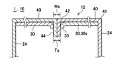
図3は、図2に示した箱1を矢印F3−F3の方向で見た断面状態を拡大し一部省略して示す拡大断面図である。
図4は、図2に示した箱1を矢印F4−F4の方向で見た断面状態を拡大し一部省略して示す拡大断面図である。
FIG. 3 is an enlarged cross-sectional view showing the box 1 shown in FIG. 2 in an enlarged cross-sectional state as viewed in the direction of arrows F3-F3 with a part omitted.
FIG. 4 is an enlarged cross-sectional view showing the box 1 shown in FIG. 2 in an enlarged cross-sectional state as viewed in the direction of arrows F4-F4 with a part omitted.
位置決め幅Wsは、一対の嵌め込み部44が互いに重ねられて位置決め部35に嵌め込まれるときの厚みTsと略等しい。位置決め幅Wsは、一対の嵌め込み部44が重ねられたときの厚みTsと略等しいので嵌め込み部44の嵌め込みと位置決めとを確実に実現しやすい。嵌め込み部44は、外蓋40の端部がそのまま延長して形成されている。
位置決め幅Wsと、重ねた2つの嵌め込み部44の厚みTsとは略等しい寸法であるので相互に滑り合う程度の摩擦を生じる。つまり、分割内蓋30sの端面と嵌め込み部44の平面とは滑り合う位置関係を有するので正確に位置決めしやすい。したがって、位置決め幅Wsは、嵌め込み部44に対する位置決めを正確にしやすくなる。
位置決め幅Ws(一対の位置決め部35の間の幅)は、嵌め込み部44に対して互いに摩擦力が作用する状態とされた摩擦部33とは異なって、嵌め込み部44の厚みTs(対向して重ねられた2枚で一対の嵌め込み部44の板厚)と略同じ寸法に形成されている。つまり、位置決め幅Wsは、2枚の嵌め込み部44の厚みTsと略等しい寸法であり正確に位置決めされやすい。
例えば、厚みTsが10mmの場合、位置決め幅Wsは、8mmないし12mm程度であれば略同様に作用する。
これにより、一対の分割内蓋30sの間に嵌め込み部44が挟まれ、隙間を抑制された状態で位置決めされる。位置決め部35は、嵌め込み部44の分割内蓋30sへの出し入れ、すなわち外蓋40の開閉に伴う分割内蓋30sへの作用を抑制する。
つまり、平坦に閉じた外蓋40に対する外からの開閉が容易となり、取り扱いが容易になる。また、分割内蓋30sが有する位置決め部35は、平坦となるので、外蓋40の平坦性を維持できる。
本実施の形態では、対向する一対の位置決め部35が有する対称軸AXsとの間の幅を合計して位置決め幅Wsとしている。つまり、それぞれの分割内蓋30sは、嵌め込み部44が有する板厚(Ts/2)と略同一の幅で位置決め幅Wsの半分(Ws/2)が除去され、対称軸AXsを中心として全体として2枚の嵌め込み部44の厚みTsと同一寸法となる位置決め幅Wsが形成されている。なお、製造工程における位置決め幅Wsの形成は、内蓋30を分割して形成する前の分割内蓋30sに相当する領域に対して一括して一度に実施される。
本実施の形態に係る箱1(段ボール箱10)は、形状に対する新規で有用な技術的思想の創作であるが、従来の製造工程(生産方法)とほとんど同様の製造工程で生産できる。
なお、摩擦部33を配置しないで、摩擦部33の位置に位置決め部35を延長して外蓋40を閉じる形状も考えられる。しかし、外蓋40を確実に閉じた状態にすること、また閉じた状態を確実に維持すること、逆に、必要に応じて容易に開くことなどの使い勝手を考慮すると、位置決め部35のみでの設定では本発明の作用効果(蓋の平坦性、更には開閉の容易さ)を得ることが困難であり、摩擦部33と位置決め部35との併用による作用、効果は極めて大きいことが認識された。
また、位置決め部35を摩擦部33で置き換える形状も考えられる。しかし、この場合は、外蓋40の開閉に新たな困難性が生じ、摩擦部33と位置決め部35との併用による作用、効果は極めて大きいことが認識された。
The positioning width Ws is substantially equal to the thickness Ts when the pair of
Since the positioning width Ws and the thickness Ts of the two overlapping
The positioning width Ws (width between the pair of positioning portions 35) is different from the
For example, when the thickness Ts is 10 mm, the positioning width Ws works in substantially the same manner if it is about 8 mm to 12 mm.
As a result, the
That is, the flatly closed
In the present embodiment, the widths between the pair of
The box 1 (cardboard box 10) according to the present embodiment is a creation of a new and useful technical idea for the shape, but can be produced by a manufacturing process almost the same as the conventional manufacturing process (production method).
It is also conceivable that the
Further, a shape in which the
本発明は、段ボールを使用した箱などに有効に利用できる。 The present invention can be effectively used for boxes and the like using corrugated cardboard.
1 箱
10 段ボール箱
11 直方体
12 蓋部
20 底面
21 第1辺
22 第2辺
23 第1側面
24 第2側面
30 内蓋
30s 分割内蓋
31 第1折り曲げ部
32 先端部
33 摩擦部
33f 折り目
34 切断部
35 位置決め部
40 外蓋
41 第2折り曲げ部
42 第3折り曲げ部
44 嵌め込み部
AXs対称軸
Lf 摩擦長
Lt 嵌め込み長
Ts 厚み
Ws 位置決め幅
1 box 10 cardboard box 11
Claims (5)
相互に対向する一対の第1辺、および前記第1辺に隣接して相互に対向する一対の第2辺を有する底面と、
一対の前記第1辺から立ち上がって相互に向き合う一対の第1側面と、
一対の前記第2辺から立ち上がって相互に向き合い前記第1側面にそれぞれ隣接する一対の第2側面と、
一対の前記第1側面からそれぞれ延長し、前記第1側面の上端の第1折り曲げ部でそれぞれ折り曲げられて前記底面に対向する一対の内蓋と、
一対の前記第2側面からそれぞれ延長し、前記第2側面の上端の第2折り曲げ部でそれぞれ折り曲げられ、前記内蓋を覆って前記蓋部を形成する一対の外蓋と、を備え、
一対の前記外蓋のそれぞれは、先端に、前記第2折り曲げ部と平行な第3折り曲げ部で折り曲げられて前記内蓋の下側へ嵌め込まれる一対の嵌め込み部を有し、
一対の前記内蓋のそれぞれは、前記第1折り曲げ部の中心から前記内蓋が有する先端部の中心までを対称軸として切断された一対の分割内蓋を有し、
一対の前記分割内蓋は、前記対称軸に沿ってそれぞれ対称に、前記第1折り曲げ部の側に、前記嵌め込み部が嵌め込まれるとき内側に曲げられて相互に摩擦力を生じる摩擦部と、前記先端部の側に、前記嵌め込み部を整合的に位置決めする位置決め部と、を有し、
前記摩擦部は、前記第1折り曲げ部に沿って前記対称軸に対して対称に形成された切断部によって前記第1折り曲げ部から分離されている
ことを特徴とする箱。 A box with a lid located on the top of a rectangular parallelepiped
A bottom surface having a pair of first sides facing each other and a pair of second sides adjacent to each other and facing each other.
A pair of first side surfaces that stand up from the first side and face each other,
A pair of second side surfaces that stand up from the pair of the second sides and face each other and are adjacent to the first side surface, respectively.
A pair of inner lids extending from the pair of the first side surfaces and bent at the first bent portion at the upper end of the first side surface to face the bottom surface.
A pair of outer lids extending from the pair of the second side surfaces and bent at the second bent portion at the upper end of the second side surface to cover the inner lid and form the lid portion are provided.
Each of the pair of outer lids has a pair of fitting portions at the tip thereof, which are bent at a third bending portion parallel to the second bending portion and fitted to the lower side of the inner lid.
Each of the pair of inner lids has a pair of divided inner lids cut from the center of the first bent portion to the center of the tip portion of the inner lid as an axis of symmetry.
The pair of divided inner lids are symmetrically arranged along the axis of symmetry, and are bent inward on the side of the first bent portion when the fitted portion is fitted to generate frictional force with each other. on the side of the tip, have a, a positioning portion for positioning said fitting portion aligned manner,
It said friction unit is a box, characterized in that the cutting portion is formed symmetrically with respect to the symmetry axis along the first bending portion that is separated from the first bent portion.
前記切断部は、一対の前記位置決め部の間の間隔で定まる位置決め幅と同じ寸法で切断されている
ことを特徴とする箱。 The box according to claim 1.
A box characterized in that the cut portion is cut with the same dimensions as the positioning width determined by the distance between the pair of the positioning portions.
前記位置決め幅は、一対の前記嵌め込み部が互いに重ねられて前記位置決め部に嵌め込まれるときの厚みと略等しい
ことを特徴とする箱。 The box according to claim 2.
A box characterized in that the positioning width is substantially equal to the thickness when a pair of the fitting portions are overlapped with each other and fitted into the positioning portion.
前記摩擦部は、前記第2折り曲げ部に沿う方向で略30mmの摩擦長を有する
ことを特徴とする箱。 The box according to any one of claims 1 to 3.
The friction portion is a box having a friction length of about 30 mm in a direction along the second bent portion.
前記直方体は、段ボールで形成されている
ことを特徴とする箱。 The box according to any one of claims 1 to 4.
The rectangular parallelepiped is a box characterized in that it is made of corrugated cardboard.
Priority Applications (1)
| Application Number | Priority Date | Filing Date | Title |
|---|---|---|---|
| JP2016175102A JP6845552B2 (en) | 2016-09-07 | 2016-09-07 | box |
Applications Claiming Priority (1)
| Application Number | Priority Date | Filing Date | Title |
|---|---|---|---|
| JP2016175102A JP6845552B2 (en) | 2016-09-07 | 2016-09-07 | box |
Publications (2)
| Publication Number | Publication Date |
|---|---|
| JP2018039533A JP2018039533A (en) | 2018-03-15 |
| JP6845552B2 true JP6845552B2 (en) | 2021-03-17 |
Family
ID=61625009
Family Applications (1)
| Application Number | Title | Priority Date | Filing Date |
|---|---|---|---|
| JP2016175102A Expired - Fee Related JP6845552B2 (en) | 2016-09-07 | 2016-09-07 | box |
Country Status (1)
| Country | Link |
|---|---|
| JP (1) | JP6845552B2 (en) |
Family Cites Families (7)
| Publication number | Priority date | Publication date | Assignee | Title |
|---|---|---|---|---|
| JPS4421671Y1 (en) * | 1966-05-07 | 1969-09-12 | ||
| JPS63178937A (en) * | 1987-01-08 | 1988-07-23 | 松下電器産業株式会社 | Storage battery packaging box |
| JPH07205953A (en) * | 1994-01-26 | 1995-08-08 | Tanakaya:Kk | Cushioned container |
| JP2008239238A (en) * | 2007-03-29 | 2008-10-09 | Yasutaka Kikuchi | Container for thin article |
| JP2010030649A (en) * | 2008-07-30 | 2010-02-12 | Towa Sangyo Kk | Packaging container |
| DE102013015571A1 (en) * | 2013-09-20 | 2015-03-26 | Ipe Schropp Gbr (Vertretungsberechtigter Gesellschafter Joachim Schropp, 74831 Gundelsheim) | folding |
| JP6426492B2 (en) * | 2015-02-16 | 2018-11-21 | レンゴー株式会社 | Easy-open packaging box |
-
2016
- 2016-09-07 JP JP2016175102A patent/JP6845552B2/en not_active Expired - Fee Related
Also Published As
| Publication number | Publication date |
|---|---|
| JP2018039533A (en) | 2018-03-15 |
Similar Documents
| Publication | Publication Date | Title |
|---|---|---|
| CN1910084B (en) | Plastic box | |
| JP6132563B2 (en) | Packaging box | |
| JP6350622B2 (en) | Packaging box | |
| WO2014109133A1 (en) | Packing box | |
| JP3216513U (en) | Packaging box with lock function | |
| JP6616701B2 (en) | Packaging box | |
| JP2016150753A (en) | Easily opened packing box | |
| JP3171407U (en) | Cardboard box flap locking structure | |
| JP6845552B2 (en) | box | |
| JP2021041962A (en) | Packaging box | |
| JP3177596U (en) | Packaging box | |
| JP5464920B2 (en) | Packaging box with closed-maintenance function | |
| JP6912286B2 (en) | Lock structure and packaging box | |
| JP6513936B2 (en) | Packaging box | |
| JP6127897B2 (en) | Stacking tray combined box | |
| JP6723713B2 (en) | Tissue box case | |
| JP3201982U (en) | Simple lock packaging box | |
| JP3182826U (en) | Packaging box | |
| JP6476032B2 (en) | Packaging box | |
| JP3150970U (en) | Simple open packaging box | |
| JP6821975B2 (en) | Packaging box | |
| JP2021059346A (en) | Packaging container | |
| JP2016084167A (en) | Lock structure | |
| JP5963521B2 (en) | A container for storing a wound body wound with a long object and a container containing the wound body | |
| JP7672781B2 (en) | Packaging box |
Legal Events
| Date | Code | Title | Description |
|---|---|---|---|
| A621 | Written request for application examination |
Free format text: JAPANESE INTERMEDIATE CODE: A621 Effective date: 20190713 |
|
| A977 | Report on retrieval |
Free format text: JAPANESE INTERMEDIATE CODE: A971007 Effective date: 20200615 |
|
| A131 | Notification of reasons for refusal |
Free format text: JAPANESE INTERMEDIATE CODE: A131 Effective date: 20200804 |
|
| A521 | Request for written amendment filed |
Free format text: JAPANESE INTERMEDIATE CODE: A523 Effective date: 20200825 |
|
| TRDD | Decision of grant or rejection written | ||
| A01 | Written decision to grant a patent or to grant a registration (utility model) |
Free format text: JAPANESE INTERMEDIATE CODE: A01 Effective date: 20210216 |
|
| A61 | First payment of annual fees (during grant procedure) |
Free format text: JAPANESE INTERMEDIATE CODE: A61 Effective date: 20210218 |
|
| R150 | Certificate of patent or registration of utility model |
Ref document number: 6845552 Country of ref document: JP Free format text: JAPANESE INTERMEDIATE CODE: R150 |
|
| LAPS | Cancellation because of no payment of annual fees |