JP6844702B2 - Equipment protection device and equipment protection method - Google Patents
Equipment protection device and equipment protection method Download PDFInfo
- Publication number
- JP6844702B2 JP6844702B2 JP2019532331A JP2019532331A JP6844702B2 JP 6844702 B2 JP6844702 B2 JP 6844702B2 JP 2019532331 A JP2019532331 A JP 2019532331A JP 2019532331 A JP2019532331 A JP 2019532331A JP 6844702 B2 JP6844702 B2 JP 6844702B2
- Authority
- JP
- Japan
- Prior art keywords
- temperature
- controller
- threshold value
- sensor
- temperature difference
- Prior art date
- Legal status (The legal status is an assumption and is not a legal conclusion. Google has not performed a legal analysis and makes no representation as to the accuracy of the status listed.)
- Active
Links
Images


Classifications
-
- H—ELECTRICITY
- H02—GENERATION; CONVERSION OR DISTRIBUTION OF ELECTRIC POWER
- H02M—APPARATUS FOR CONVERSION BETWEEN AC AND AC, BETWEEN AC AND DC, OR BETWEEN DC AND DC, AND FOR USE WITH MAINS OR SIMILAR POWER SUPPLY SYSTEMS; CONVERSION OF DC OR AC INPUT POWER INTO SURGE OUTPUT POWER; CONTROL OR REGULATION THEREOF
- H02M1/00—Details of apparatus for conversion
- H02M1/32—Means for protecting converters other than automatic disconnection
-
- H—ELECTRICITY
- H02—GENERATION; CONVERSION OR DISTRIBUTION OF ELECTRIC POWER
- H02P—CONTROL OR REGULATION OF ELECTRIC MOTORS, ELECTRIC GENERATORS OR DYNAMO-ELECTRIC CONVERTERS; CONTROLLING TRANSFORMERS, REACTORS OR CHOKE COILS
- H02P27/00—Arrangements or methods for the control of AC motors characterised by the kind of supply voltage
- H02P27/04—Arrangements or methods for the control of AC motors characterised by the kind of supply voltage using variable-frequency supply voltage, e.g. inverter or converter supply voltage
- H02P27/06—Arrangements or methods for the control of AC motors characterised by the kind of supply voltage using variable-frequency supply voltage, e.g. inverter or converter supply voltage using dc to ac converters or inverters
- H02P27/08—Arrangements or methods for the control of AC motors characterised by the kind of supply voltage using variable-frequency supply voltage, e.g. inverter or converter supply voltage using dc to ac converters or inverters with pulse width modulation
- H02P27/085—Arrangements or methods for the control of AC motors characterised by the kind of supply voltage using variable-frequency supply voltage, e.g. inverter or converter supply voltage using dc to ac converters or inverters with pulse width modulation wherein the PWM mode is adapted on the running conditions of the motor, e.g. the switching frequency
-
- H—ELECTRICITY
- H02—GENERATION; CONVERSION OR DISTRIBUTION OF ELECTRIC POWER
- H02M—APPARATUS FOR CONVERSION BETWEEN AC AND AC, BETWEEN AC AND DC, OR BETWEEN DC AND DC, AND FOR USE WITH MAINS OR SIMILAR POWER SUPPLY SYSTEMS; CONVERSION OF DC OR AC INPUT POWER INTO SURGE OUTPUT POWER; CONTROL OR REGULATION THEREOF
- H02M1/00—Details of apparatus for conversion
- H02M1/32—Means for protecting converters other than automatic disconnection
- H02M1/327—Means for protecting converters other than automatic disconnection against abnormal temperatures
-
- H—ELECTRICITY
- H02—GENERATION; CONVERSION OR DISTRIBUTION OF ELECTRIC POWER
- H02P—CONTROL OR REGULATION OF ELECTRIC MOTORS, ELECTRIC GENERATORS OR DYNAMO-ELECTRIC CONVERTERS; CONTROLLING TRANSFORMERS, REACTORS OR CHOKE COILS
- H02P29/00—Arrangements for regulating or controlling electric motors, appropriate for both AC and DC motors
- H02P29/60—Controlling or determining the temperature of the motor or of the drive
- H02P29/62—Controlling or determining the temperature of the motor or of the drive for raising the temperature of the motor
-
- H—ELECTRICITY
- H02—GENERATION; CONVERSION OR DISTRIBUTION OF ELECTRIC POWER
- H02P—CONTROL OR REGULATION OF ELECTRIC MOTORS, ELECTRIC GENERATORS OR DYNAMO-ELECTRIC CONVERTERS; CONTROLLING TRANSFORMERS, REACTORS OR CHOKE COILS
- H02P29/00—Arrangements for regulating or controlling electric motors, appropriate for both AC and DC motors
- H02P29/60—Controlling or determining the temperature of the motor or of the drive
- H02P29/68—Controlling or determining the temperature of the motor or of the drive based on the temperature of a drive component or a semiconductor component
-
- H—ELECTRICITY
- H05—ELECTRIC TECHNIQUES NOT OTHERWISE PROVIDED FOR
- H05K—PRINTED CIRCUITS; CASINGS OR CONSTRUCTIONAL DETAILS OF ELECTRIC APPARATUS; MANUFACTURE OF ASSEMBLAGES OF ELECTRICAL COMPONENTS
- H05K7/00—Constructional details common to different types of electric apparatus
- H05K7/20—Modifications to facilitate cooling, ventilating, or heating
- H05K7/2089—Modifications to facilitate cooling, ventilating, or heating for power electronics, e.g. for inverters for controlling motor
Description
本発明は、機器保護装置及び機器保護方法に関するものである。 The present invention relates to a device protection device and a device protection method.
温度センサでインバータ温度を検出し、温度変化量を計算し、温度変化量が閾値より大きいときには、インバータ温度の修正を行い。さらに修正後のインバータ温度になまし処理を行い、なまし処理の処理済み温度が上限温度より大きい場合には、負荷制限率設定し、モータのトルクに制限をかける方法が知られている(特許文献1)。 The temperature sensor detects the inverter temperature, calculates the amount of temperature change, and if the amount of temperature change is larger than the threshold value, corrects the inverter temperature. Further, a method is known in which annealing treatment is performed to the corrected inverter temperature, and when the processed temperature of the smoothing treatment is larger than the upper limit temperature, a load limit rate is set to limit the torque of the motor (patented). Document 1).
しかしながら、周辺温度が高温の時には、トルク制限が適切なタイミングにかからず、発熱部分が高温になるという問題がある。 However, when the ambient temperature is high, there is a problem that the torque limit is not applied at an appropriate timing and the heat generating portion becomes high.
本発明が解決しようとする課題は、発熱部分の温度上昇を抑制できる機器保護装置及び機器保護方法を提供することである。 An object to be solved by the present invention is to provide a device protection device and a device protection method capable of suppressing a temperature rise of a heat generating portion.
本発明は、機器の冷却に使用される冷媒の温度と機器の温度をそれぞれ検出し、冷媒の検出温度と機器の検出温度の温度差を演算し、温度差が所定の温度差閾値より高い場合に機器に対して駆動制限をかけ、機器の検出温度が所定の温度閾値より高い場合に機器に対して駆動制限をかけることによって上記課題を解決する。 The present invention detects the temperature of the refrigerant used for cooling the equipment and the temperature of the equipment, respectively, calculates the temperature difference between the detection temperature of the refrigerant and the detection temperature of the equipment, and when the temperature difference is higher than a predetermined temperature difference threshold. The above problem is solved by applying a drive limit to the device and applying a drive limit to the device when the detected temperature of the device is higher than a predetermined temperature threshold.
本発明によれば、発熱部分の温度上昇を抑制できる。 According to the present invention, the temperature rise of the heat generating portion can be suppressed.
以下、本発明の実施形態を図面に基づいて説明する。本実施形態に係る機器保護装置は、発熱体を含む機器の温度上昇を抑制する装置である。機器保護装置は、例えば車両に搭載される駆動システムに設けられ、駆動システムに含まれる機器の温度を管理しつつ、機器の温度上昇を抑制している。 Hereinafter, embodiments of the present invention will be described with reference to the drawings. The device protection device according to the present embodiment is a device that suppresses a temperature rise of a device including a heating element. The device protection device is provided in, for example, a drive system mounted on a vehicle, and controls the temperature of the device included in the drive system while suppressing the temperature rise of the device.
以下の説明では、機器保護装置が車両用の駆動システムに設けられた例を説明する。なお、機器保護装置は、必ずしも駆動システムに設けられる必要はなく、発熱部分を含んだ他のシステムに設けられてよい。また機器保護装置は、車両に限らず他の装置に設けられてもよい。 In the following description, an example in which the device protection device is provided in the drive system for the vehicle will be described. The device protection device does not necessarily have to be provided in the drive system, and may be provided in another system including a heat generating portion. Further, the device protection device may be provided not only in the vehicle but also in other devices.
図1は、本実施形態に係る機器保護装置を含む駆動システムのブロック図である。駆動システムは、電源1、負荷2、電力変換装置3、冷却装置4、及びコントローラ10を備えている。
FIG. 1 is a block diagram of a drive system including a device protection device according to the present embodiment. The drive system includes a
電源1は、車両の電力源であって、リチウムイオン電池などの二次電池を並列又は直列に接続した電池群である。負荷2は、モータ(電動機)であり、車輪に対して回転力を与えるように車輪と連結されている。負荷2には、例えば三相交流モータが用いられる。
The
電力変換装置3は、電源1と負荷2との間に接続されている。電力変換装置3は、インバータ回路及び制御回路等を有している。インバータ回路は、IGBT等のスイッチング素子をブリッジ状に接続した、2相3相変換を可能とする回路である。インバータ回路は、負荷2と電源1との間に接続されている。インバータ回路は、複数のスイッチング素子を直列に接続した直列回路を、3相分並列に接続している。インバータ回路において、上アームのスイッチング素子と下アームのスイッチング素子との各接続点は、モータ側のUVW相の出力端子に接続されている。また、インバータ回路は、平滑コンデンサを有している。平滑コンデンサは、電源1の入出力電圧を平滑し、ブリッジ状のスイッチング素子の回路と電源1側の接続端子との間に接続されている。
The power conversion device 3 is connected between the
電力変換装置3は、装置の内部温度を検出するための温度センサ21を有している。電力変換装置3は、インバータ回路に含まれるスイッチング素子のオン、オフを切り換えることで電力変換を行う。スイッチング素子がオン、オフ動作を行うと、スイッチング損失等により発熱する。スイッチング素子はパワーモジュールとしてモジュール化されており、電力変換装置3の内部に設けられている。温度センサ21は、スイッチング素子のスイッチング動作によって上昇するパワーモジュールの温度を検出している。温度センサ21はパワーモジュールに設置されている。温度センサ21は検出値をコントローラ10に出力する。なお、温度センサ21の検出値は、電力変換装置3内のコントローラを介して、コントローラ10に出力されてもよい。なお、温度センサ21は、パワーモジュールに限らず、電力変換装置3の他の内部部品の温度を検出できるように、電力変換装置に設けられてもよい。
The power conversion device 3 has a
冷却装置4は、電力変換装置3内に冷媒を循環させることで、電力変換装置3を冷却する。冷却装置4は、冷媒を出力するためのポンプ、冷媒量を調整するための調整弁、熱交換器等を有している。冷却装置4と電力変換装置3との間は、冷媒を通す流路で接続されている。流路は、冷却装置4から出て、電力変換装置の内部を通り、冷却装置4に戻るように形成されている。冷媒は、パワーモジュールの冷却に使用され、水などの液体、冷媒ガス等である。
The
冷却装置4は、冷媒の温度を検出するための温度センサ22を有している。温度センサ22は流路に設けられている。温度センサ22は、検出値をコントローラ10に出力する。
The
コントローラ10は、機器保護装置の制御処理を実行するコンピュータであり、温度センサ21の検出温度及び温度センサ22の検出温度に基づき電力変換装置3を制御することで、電力変換装置3を保護する。コントローラ10は、電力変換装置3を保護するための制御を実行させるプログラムが格納されたROM(Read Only Memory)と、このROMに格納されたプログラムを実行するためのCPU(Central Processing Unit)と、アクセス可能な記憶装置として機能するRAM(Random Access Memory)と、を備える。コントローラ10は、電力変換装置3内のコントローラと信号線で接続されている。なお、コントローラ10は、電力変換装置3内に設けられて、コントローラ10が、スイッチング動作を制御する機能を有してもよい。また、コントローラ10は、パワーモジュール内のスイッチング素子を直接制御してもよい。
The
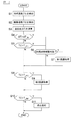
次に、コントローラ10による電力変換装置3を保護するための制御フローを、図2を用いて説明する。コントローラ10は、電力変換装置3の駆動中、以下の制御フローを所定の周期で実行している。
Next, a control flow for protecting the power conversion device 3 by the
ステップS1にて、コントローラ10は、温度センサ22を用いて、冷媒の温度(T1)を検出する。ステップS2にて、コントローラ10は、温度センサ21を用いて、電力変換装置3のパワーモジュールの温度(機器温度:T2)を検出する。
In step S1, the
ステップS3にて、コントローラ10は、検出された冷媒温度(T1)と検出された機器温度(T2)との差分を求めることで、温度差(ΔT=T2−T1)を演算する。
In step S3, the
ステップS4にて、コントローラ10は、温度差と所定の温度差閾値(ΔT_th)とを比較する。温度差閾値(ΔT_th)は予め設定された閾値である。後述するように環境温度が低い場合には、機器の温度上昇の速さは、冷媒の温度上昇の速さよりも速く、温度差の上昇も速くなる。温度差閾値(ΔT_th)は、低温状態で電力変換装置3の温度が上昇する状態で、電力変換装置3の温度が許容温度に達する前に、電力変換装置3に対して駆動制限を加えるタイミングを、温度差で示している。In step S4, the
温度差(ΔT)が温度差閾値(ΔT_th)以下である場合には、コントローラ10はステップS5の制御フローを実行する。一方、温度差(ΔT)が温度差閾値(ΔT_th)より大きい場合には、コントローラ10はステップS6の制御フローを実行する。When the temperature difference (ΔT) is equal to or less than the temperature difference threshold value (ΔT _th ), the
ステップS5にて、コントローラ10は、機器温度(T2)と温度閾値(T_th1)とを比較する。機器温度(T2)が温度閾値(T_th1)より高い場合には、コントローラ10はステップS6の制御フローを実行する。一方、機器温度(T2)が温度閾値(T_th1)以下である場合には、コントローラ10はステップS8の制御フローを実行する。温度閾値(T_th1)は、後述する第1保護処理を実行するか否かを判定するための閾値であり、温度差閾値(ΔT_th)よりも高い温度に設定されている。温度差閾値(ΔT_th)は低温環境用の閾値であり、温度閾値(T_th1)は高温環境用の閾値である。In step S5, the
ステップS6にて、コントローラ10は、現在のモータの駆動状態に基づき、スイッチング周波数の制限が可能であるか否かを判定する。コントローラ10は、電力変換装置3から、モータ回転数を取得することで、モータの駆動状態を確認する。スイッチング周波数は、スイッチング素子のオン、オフを制御する際のキャリア周波数である。温度差(ΔT)が温度差閾値(ΔT_th)より高い場合、又は、機器温度(T2)が温度閾値(T1_th1)より高い場合には、パワーモジュールの温度上昇を抑制するために、パワーモジュールに対して駆動制限をかける。パワーモジュールに駆動制限をかけることで、モータの駆動にも制限がかかる。駆動制限は、キャリア周波数を現在の周波数より低くすることで実行される。しかしながら、モータの回転数が高い状態でスイッチング周波数を低く設定した場合には、制御発散する可能性がある。そこで、ステップS6の制御フローでは、モータの駆動状態が、スイッチング周波数を低く設定できる状態にあるか否かを判定する。具体的には、コントローラ10は、現在のモータ回転数と回転数閾値とを比較し、現在のモータ回転数(N)が回転数閾値(Nth)より低い場合にはスイッチング周波数を制限できると判定し、現在のモータ回転数が回転数閾値以上である場合にはスイッチング周波数を制限できないと判定する。回転数閾値は予め設定されており、モータのトルクに応じた値にしてもよい。In step S6, the
スイッチング周波数を制限できると判定された場合には、ステップS7にて、コントローラ10は第1保護処理を実行する。第1保護処理は、スイッチング周波数に制限をかけることで、モータに対して駆動制限をかける。具体的には、コントローラ10は、電力変換装置3から現在のモータの出力トルク及びモータ回転数を取得する。選択可能なスイッチング周波数は予め設定されており、モータの駆動状態に応じて、選択可能なスイッチング周波数が異なる。
If it is determined that the switching frequency can be limited, the
例えば、選択可能なスイッチング周波数として、3つの周波数(fsw1、fsw2、fsw3)が予め設定されている。ただし、周波数(fsw3)が最も高く、周波数(fsw1)が最も低い。また、回転数閾値より低い回転数閾値(Nth_L)が予め設定されている。そして、モータの現在の回転数に応じて、選択可能なスイッチン周波数が決まる。モータの現在の回転数Nが回転数閾値(Nth)より高い場合には、選択可能なスイッチング周波数はfsw3のみであり、スイッチング周波数の制限ができない状態に相当する。モータの現在の回転数が回転数閾値(Nth)以下で、回転数閾値(Nth_L)より高い場合には、選択可能なスイッチング周波数は、周波数(fsw3)及び周波数(fsw2)である。そして、例えば、現在のキャリア周波数が周波数(fsw2)より高く周波数(fsw3)より低い場合には、コントローラ10は、キャリア周波数を周波数(fsw2)に設定し、キャリア周波数に対して制限をかける。また、モータの現在の回転数が回転数閾値(Nth_L)以下である場合には、選択可能なスイッチング周波数は、周波数(fsw1)、周波数(fsw2)、周波数(fsw3)である。例えば、現在のキャリア周波数が周波数(fsw3)より高い場合は、コントローラ10は、キャリア周波数を周波数(fsw3)に設定し、キャリア周波数に対して制限をかける。すなわち、コントローラ10は、モータの現在の回転数に応じて選択可能なスイッチング周波数が複数ある場合には、現在のキャリア周波数よりも低いキャリア周波数に設定する。これにより、損失が抑制され、パワーモジュールの発熱を抑制できる。なお、選択可能なスイッチング周波数は、モータ回転数に限らず、モータのトルクにより決定してもよい。For example, three frequencies (f sw1 , f sw2 , and f sw3 ) are preset as selectable switching frequencies. However, the frequency (f sw3 ) is the highest and the frequency (f sw1 ) is the lowest. Further, a rotation speed threshold value ( Nth_L ) lower than the rotation speed threshold value is set in advance. Then, the selectable switching frequency is determined according to the current rotation speed of the motor. If the current rotational speed N of the motor is higher than the rotation speed threshold value (N th), the switching frequency selectable is only f sw3, corresponds to a state that can not switching frequency limitation. Current rotational speed of the motor is below the rotational speed threshold value (N th), is higher than the rotation speed threshold value (N th - L), the switching frequency selectable is the frequency (f sw3) and frequency (f sw2) .. Then, for example, when the current carrier frequency is higher than the frequency (f sw2 ) and lower than the frequency (f sw3 ), the
ステップS8にて、コントローラ10は、機器温度(T2)と温度閾値(T_th2)とを比較する。温度閾値(T_th2)は、後述する第2保護処理を実行するか否かを判定するための閾値であり、温度閾値(T_th1)よりも高い温度に設定されている。機器温度(T2)が温度閾値(T_th2)より高い場合には、コントローラ10はステップS9の制御フローを実行する。一方、機器温度(T2)が温度閾値(T_th2)以下である場合には、コントローラ10はステップS10の制御フローを実行する。In step S8, the
ステップS9にて、コントローラ10は、第2保護処理を実行する。第2保護処理は、機器温度(T2)が温度閾値(T_th2)に達した時点の要求トルクを、モータからの最大出力に設定することで、モータからの出力トルクに制限をかける。具体的には、機器温度(T2)が温度閾値(T_th2)に達した場合に、コントローラ10は、電力変換装置3のコントローラに対して、要求トルクに応じたトルク指令値の上限を現在のトルク指令値にするよう、指令信号を送信する。電力変換装置3のコントローラは、指令信号を受信したとき、現在のトルク指令を上限値に設定する。上限値が設定された後に、ドライバーのアクセル操作により、トルク指令の上限値を超えるような要求トルクが入力された場合でも、コントローラは、トルク指令値を上限値に制限した上で、モータの現在の回転数、モータの現在の電流に応じたスイッチング信号を生成し、スイッチング素子を制御する。これにより、要求トルクに制限が加わるため、モータの出力トルクが抑制され、その結果として、パワーモジュールの温度が抑制される。In step S9, the
ステップS10にて、コントローラ10は、機器温度(T2)と上限温度(T_fail)とを比較する。上限温度(T_fail)は、パワーモジュールに許容される温度の上限値を示しており、温度閾値(T_th1)及び温度閾値(T_th2)よりも高い温度に設定されている。機器温度(T2)が上限温度(T_fail)より高い場合には、コントローラ10はステップS11の制御フローを実行する。一方、機器温度(T2)が上限温度(T_fail)以下である場合には、コントローラ10は制御フローを終了する。In step S10, the
ステップS11にて、コントローラ10は、電力変換装置3内のコントローラに対して、モータを強制的に停止させる旨のフェールセーフ信号を送信する。電力変換装置3内のコントローラは、フェールセーフ信号を受信した場合には、電力変換装置3の動作を停止させる(フェールセーフ処理)。これにより、パワーモジュールが上限値を超えることを防止できる。
In step S11, the
次に、図3A、図3B、図4A、図4Bを用いて、第1保護処理と温度の関係について説明する。図3A、図3Bは環境温度が低温(TL)であるときの温度特性を示し、図4A、図4Bは環境温度が高温(TH)であるときの温度特性を示す。図3A、図3B、図4A、図4Bにおいて、グラフаは温度差(ΔT)の特性を示し、グラフbは温度センサ22で検出される冷媒温度(T1)を示し、グラフcは温度センサ21で検出される機器温度(T2)を示し、グラフdはスイッチング素子の実際の温度(Tsw)を示す。また横軸は時間を示し、縦軸は温度の大きさを示す。図3A及び図4Aは、本実施形態に係る機器保護装置を駆動システムに設けない時の特性(比較例)を示している。図3B及び図4Bは、本実施形態に係る機器保護装置を駆動システムに設けたときの特性を示している。Next, the relationship between the first protection treatment and the temperature will be described with reference to FIGS. 3A, 3B, 4A, and 4B. 3A and 3B show the temperature characteristics when the environmental temperature is low ( TL ), and FIGS. 4A and 4B show the temperature characteristics when the environmental temperature is high ( TH ). In FIGS. 3A, 3B, 4A, and 4B, graph а shows the characteristics of the temperature difference (ΔT), graph b shows the refrigerant temperature (T1) detected by the
図3Aに示すように、環境温度が低い時には、機器温度(T2)は、時刻t2の時点で温度閾値(T_th1)に達する。一方、温度差(ΔT)は、時刻t2よりも早い時刻t1の時点で、温度差閾値(ΔT_th)に達する。すなわち、低温時には、機器温度(T2)が温度閾値(T_th1)に達する前に、冷媒温度と機器温度との温度差が広がり、温度差(ΔT)は温度差閾値(ΔT_th)に達する。そして、図3Bに示すように、本実施形態では、温度差(ΔT)が温度差閾値(ΔT_th)に達した時点で、第1保護処理が実行されるため、スイッチング素子の温度が高温になる前に損失が低減され、スイッチング素子温度(Tsw)を抑制できる。一方、第1保護処理を実行しない比較例では、時刻t1以降も、スイッチング素子温度(Tsw)は上昇し続ける。As shown in FIG. 3A, when the environmental temperature is low, device temperature (T2) reaches a temperature threshold value (T_ th1) at time t2. On the other hand, the temperature difference (ΔT) reaches the temperature difference threshold (ΔT _th) at the time t1 earlier than the time t2. That is, at the time of low temperature, before device temperature (T2) is to reach the temperature threshold value (T_ th1), spreading the temperature difference between the refrigerant temperature and the device temperature, the temperature difference ([Delta] T) reaches a temperature difference threshold ([Delta] T - th). Then, as shown in FIG. 3B, in the present embodiment, when the temperature difference (ΔT) reaches the temperature difference threshold value ( ΔT_th ), the first protection process is executed, so that the temperature of the switching element becomes high. The loss is reduced and the switching element temperature (Tsw) can be suppressed. On the other hand, in the comparative example in which the first protection process is not executed, the switching element temperature (Tsw) continues to rise even after the time t1.
図4Aに示すように、環境温度が高い時には、温度差(ΔT)が温度差閾値(ΔT_th)に達する時点(時刻t4)よりも先に、機器温度(T2)が温度閾値(T_th1)に達する(時刻t3)。そして、図4Bに示すように、本実施形態では、温度差(T2)が温度閾値(T_th1)に達した時点で、第1保護処理が実行されるため、スイッチング素子の温度が高温になる前に損失が低減され、スイッチング素子温度(Tsw)を抑制できる。As shown in FIG. 4A, when the environmental temperature is high, before the time point (time t 4) the temperature difference ([Delta] T) reaches a temperature difference threshold ([Delta] T - th), instrument temperature (T2) is a temperature threshold (T_ th1 ) Is reached (time t 3 ). Then, as shown in FIG. 4B, in the present embodiment, when the temperature difference (T2) has reached a temperature threshold value (T_ th1), since the first protective process is performed, the temperature of the switching element becomes high Previously, the loss is reduced and the switching element temperature (Tsw) can be suppressed.
次に、図5A、図5B、図6A、図6Bを用いて、第2保護処理と温度の関係について説明する。図5A、図5Bは環境温度が低温(TL)であるときの温度特性を示し、図6A、図6Bは環境温度が高温(TH)であるときの温度特性を示す。図5A、図5B、図6A、図6Bにおいて、グラフаは温度差(ΔT)の特性を示し、グラフbは温度センサ22で検出される冷媒温度(T1)を示し、グラフcは温度センサ21で検出される機器温度(T2)を示し、グラフdはスイッチング素子の実際の温度(Tsw)を示す。また横軸は時間を示し、縦軸は温度の大きさを示す。図5A及び図6Aは、本実施形態に係る機器保護装置が第1保護処理のみをした場合の特性を示しており、図5B及び図6Bは、本実施形態に係る機器保護装置が第1保護処理及び第2保護処理をした場合の特性を示している。Next, the relationship between the second protection treatment and the temperature will be described with reference to FIGS. 5A, 5B, 6A, and 6B. 5A and 5B show the temperature characteristics when the environmental temperature is low ( TL ), and FIGS. 6A and 6B show the temperature characteristics when the environmental temperature is high ( TH ). In FIGS. 5A, 5B, 6A, and 6B, graph а shows the characteristics of the temperature difference (ΔT), graph b shows the refrigerant temperature (T1) detected by the
図5Aに示すように、第1保護処理後に、パワーモジュールの温度が上昇し続けた場合には、機器温度(T2)が時刻(t5)の時点で上限温度(T_fail)に達するため、フェールセーフ処理が実行される。一方、本実施形態では、図5Bに示すように、機器温度(T2)が上限温度(T_fail)に達する前に、機器温度(T2)が温度閾値(T_th2)に達した時点で、第2保護処理が実行され、機器温度(T2)が温度閾値(T_th2)に達した時点の出力を上限として、トルク制限がかかる。これにより、スイッチング素子の温度上昇を抑制し、電力変換装置3の動作可能な時間を延ばすことができる。As shown in FIG. 5A, after the first protection process, when the temperature of the power module continues to rise, to reach the upper limit temperature (T_ fail) at the time of equipment temperature (T2) is the time (t 5), Fail-safe processing is performed. On the other hand, in the present embodiment, as shown in FIG. 5B, before device temperature (T2) is to reach the upper limit temperature (T_ fail), when the device temperature (T2) has reached a temperature threshold value (T_ th2), the 2 The protection process is executed, and the torque is limited with the output at the time when the device temperature (T2) reaches the temperature threshold value ( T_th2) as the upper limit. As a result, the temperature rise of the switching element can be suppressed, and the operating time of the power conversion device 3 can be extended.
図6Aに示すように、第1保護処理後に、パワーモジュールの温度が上昇し続けた場合には、機器温度(T2)が時刻(t6)の時点で上限温度(T_fail)に達するため、フェールセーフ処理が実行される。一方、本実施形態では、図6Bに示すように、機器温度(T2)が上限温度(T_fail)に達する前に、機器温度(T2)が温度閾値(T_th2)に達した時点で、第2保護処理が実行され、機器温度(T2)が温度閾値(T_th2)に達した時点の出力を上限として、トルク制限がかかる。これにより、環境温度の高温時も、スイッチング素子の温度上昇を抑制し、電力変換装置3の動作可能な時間を延ばすことができる。As shown in FIG. 6A, after the first protection process, when the temperature of the power module continues to rise, to reach the upper limit temperature (T_ fail) at the time of equipment temperature (T2) is the time (t 6), Fail-safe processing is performed. On the other hand, in the present embodiment, as shown in FIG. 6B, before device temperature (T2) is to reach the upper limit temperature (T_ fail), when the device temperature (T2) has reached a temperature threshold value (T_ th2), the 2 The protection process is executed, and the torque is limited with the output at the time when the device temperature (T2) reaches the temperature threshold value ( T_th2) as the upper limit. As a result, even when the environmental temperature is high, it is possible to suppress the temperature rise of the switching element and extend the operating time of the power conversion device 3.
上記のように本実施形態に係る機器保護装置は、パワーモジュール等の機器の冷却に使用される冷媒の温度と機器の温度をそれぞれ検出し、冷媒の検出温度と機器の検出温度の温度差を演算し、温度差が温度差閾値(ΔTth)より高い場合に機器に対して駆動制限をかけ、機器の検出温度が温度閾値(T_th1)より高い場合に機器に対して駆動制限をかける。これにより、発熱体の温度上昇を抑制し、発熱体又は機器加える熱負荷を抑制できる。また機器の動作時間を延ばすことができる。As described above, the device protection device according to the present embodiment detects the temperature of the refrigerant used for cooling the device such as the power module and the temperature of the device, respectively, and determines the temperature difference between the detection temperature of the refrigerant and the detection temperature of the device. calculated, multiplied by the driving restriction to the device when the temperature difference is higher than the temperature difference threshold ([Delta] T th), applying a drive limiting to the device when the detected temperature of the device is higher than the temperature threshold value (T_ th1). As a result, the temperature rise of the heating element can be suppressed, and the heat load applied to the heating element or the device can be suppressed. In addition, the operating time of the device can be extended.
また本実施形態では、機器の検出温度が温度閾値(T_th2)より高い場合には、機器の検出温度が上昇し温度閾値(T_th2)に達した時点の出力を、機器からの最大出力に設定する。これにより、発熱体の温度を上げる直接の原因となっている出力を制限し、機器の動作可能な時間を拡大することができる。In this embodiment also, when the detected temperature of the device is higher than the temperature threshold value (T_ th2) is the output at which the detected temperature of the device reaches the elevated temperature threshold (T_ th2), the maximum output from the device Set. As a result, the output that is the direct cause of raising the temperature of the heating element can be limited, and the operating time of the device can be extended.
また本実施形態では、機器の駆動制限として、スイッチング素子のスイッチング周波数を、現在の周波数よりも低い周波数に設定する。これにより、損失を低減することで、電力変換装置の出力に制限を掛けずに、温度上昇を抑制できる。 Further, in the present embodiment, the switching frequency of the switching element is set to a frequency lower than the current frequency as a drive limitation of the device. As a result, by reducing the loss, it is possible to suppress the temperature rise without limiting the output of the power converter.
また本実施形態では、駆動制限として、モータの回転数に応じて、スイッチング素子のスイッチング周波数に制限をかける。これにより、モータ回転数に応じた最適な周波数を設定し、制御発散を防止できる。 Further, in the present embodiment, as a drive limitation, the switching frequency of the switching element is limited according to the rotation speed of the motor. As a result, the optimum frequency can be set according to the motor rotation speed, and control divergence can be prevented.
また本実施形態では、機器の検出温度が温度閾値(T_fail)以上である場合には、機器の動作を停止させる。これにより、機器に異常が生じることを防止できる。In the present embodiment, the detected temperature of the device if the temperature threshold (T_ fail) or stops the operation of the equipment. As a result, it is possible to prevent an abnormality from occurring in the device.
また本実施形態の変形例として、第2保護処理は、モータからの上限出力を第1制限値に設定し、モータの出力に制限をかけた後に、機器温度が上昇する場合には、モータからの上限出力を、第2制限値よりも低い値に設定する。図7は、機器温度と、モータからの上限出力の制限値の関係を示すグラフである。 Further, as a modification of the present embodiment, in the second protection process, when the upper limit output from the motor is set to the first limit value and the device temperature rises after limiting the output of the motor, the motor is used. The upper limit output of is set to a value lower than the second limit value. FIG. 7 is a graph showing the relationship between the equipment temperature and the limit value of the upper limit output from the motor.
図7に示すように、機器温度(T2)が温度閾値(T_th2)以下である場合には、モータからの上限出力がPth1に設定される。そのため、モータからの出力は上限値(Pth1)以下に抑制される。さらに、モータからの出力を上限値(Pth1)に制限した状態で、機器温度(T2)が温度閾値(T_th2)より高くなる場合には、コントローラ10は、図7に示す関係性に基づき、モータからの上限出力に対して更なる制限がかかる。コントローラ10は、図7の関係性を示すマップを記憶している。コントローラ10は、マップを参照しつつ、機器温度(T2>T_th2)に対応する上限値(Pth)を特定し、特定された上限値で、モータからの出力に制限を加える。これにより、変形例に係る保機器護装置は、発熱体の温度上昇を抑制できる。また、出力を完全に止めていないため、最低限の動力性能は維持できる。As shown in FIG. 7, when the device temperature (T2) is equal to or lower than the temperature threshold value (T_th2 ), the upper limit output from the motor is set to Pth1. Therefore, the output from the motor is suppressed to the upper limit value (P th1) or less. Furthermore, while limiting the output from the motor to the upper limit value (P th1), when the device temperature (T2) is higher than the temperature threshold value (T_ th2), the
なお、機器温度と上限値の関係性は、図8のグラフで示すような関係性でもよい。図8では、機器温度(T2)が温度閾値(T_th2)より高くなるにつれて、モータからの出力の上限値が比例関係で小さくなっている。The relationship between the device temperature and the upper limit value may be the relationship shown in the graph of FIG. In FIG. 8, as the device temperature (T2) becomes higher than the temperature threshold value (T_th2 ), the upper limit of the output from the motor becomes smaller in a proportional relationship.
1…電源
2…負荷
3…電力変換装置
4…冷却装置
10…コントローラ
21、22…温度センサ1 ...
Claims (7)
前記機器の温度を検出する第2センサと、
前記第1センサにより検出された第1検出温度、及び、前記第2センサにより検出された第2検出温度に基づき、前記機器に対して駆動制限をかけるコントローラとを備え、
前記コントローラは、
前記第1検出温度と前記第2検出温度との温度差を演算し、
前記温度差が所定の温度差閾値より高い場合に、前記機器に対して前記駆動制限をかけ、
前記温度差が前記所定の温度差閾値より低く、かつ、前記第2検出温度が所定の第1温度閾値より高い場合に、前記機器に対して前記駆動制限をかける機器保護装置。The first sensor that detects the temperature of the refrigerant used to cool the equipment including the heating element, and
A second sensor that detects the temperature of the device and
A controller that limits the drive of the device based on the first detection temperature detected by the first sensor and the second detection temperature detected by the second sensor is provided.
The controller
The temperature difference between the first detection temperature and the second detection temperature is calculated, and the temperature difference is calculated.
When the temperature difference is higher than a predetermined temperature difference threshold value, the drive limit is applied to the device.
A device protection device that imposes a drive limit on the device when the temperature difference is lower than the predetermined temperature difference threshold value and the second detection temperature is higher than the predetermined first temperature threshold value.
前記第2検出温度が所定の第2温度閾値より高い場合には、前記第2検出温度が上昇し前記第2温度閾値に達した時点の出力を、前記機器からの最大出力に設定する請求項1記載の機器保護装置。The controller
A claim that when the second detection temperature is higher than a predetermined second temperature threshold value, the output at the time when the second detection temperature rises and reaches the second temperature threshold value is set as the maximum output from the device. 1. The device protection device according to 1.
前記第2センサは、前記スイッチング素子の温度を検出し、
前記コントローラは、前記駆動制限として、前記スイッチング素子のスイッチング周波数を、現在の周波数よりも低い周波数に設定する請求項1又は2記載の機器保護装置。The device has a switching element
The second sensor detects the temperature of the switching element and
The device protection device according to claim 1 or 2, wherein the controller sets the switching frequency of the switching element to a frequency lower than the current frequency as the drive limit.
前記第2センサは、前記スイッチング素子の温度を検出し、
前記コントローラは、前記駆動制限として、前記モータの回転数に応じて、前記スイッチング素子のスイッチング周波数に制限をかける請求項1〜3のいずれか一項に記載の機器保護装置。The device has a switching element connected to a motor.
The second sensor detects the temperature of the switching element and
The device protection device according to any one of claims 1 to 3, wherein the controller limits the switching frequency of the switching element according to the rotation speed of the motor as the drive limit.
前記駆動制限として前記機器からの上限出力を第1制限値に設定し、
前記機器からの出力に制限をかけた後に、前記第2検出温度が上昇する場合には、前記機器からの上限出力を、前記第1制限値よりも低い第2制限値に設定する請求項1〜4のいずれか一項に記載の機器保護装置。The controller
As the drive limit, the upper limit output from the device is set to the first limit value.
Claim 1 in which when the second detection temperature rises after limiting the output from the device, the upper limit output from the device is set to a second limit value lower than the first limit value. The device protection device according to any one of the items to 4.
第1センサを用いて、前記機器の冷却に使用される冷媒の温度を検出し、
第2センサを用いて、前記機器の温度を検出し、
前記第1センサにより検出された前記冷媒の検出温度と、前記第2センサにより検出された前記機器の検出温度の温度差を演算し、
前記温度差が所定の温度差閾値より高い場合に、前記機器に対して駆動制限をかけ、
前記温度差が前記所定の温度差閾値より低く、かつ、前記機器の検出温度が所定の温度閾値より高い場合に、前記機器に対して前記駆動制限をかける機器保護方法。In a protection method that uses a processor to protect equipment, including heating elements,
Using the first sensor, the temperature of the refrigerant used to cool the equipment is detected.
The temperature of the device is detected by using the second sensor.
The temperature difference between the detection temperature of the refrigerant detected by the first sensor and the detection temperature of the device detected by the second sensor is calculated.
When the temperature difference is higher than a predetermined temperature difference threshold value, a drive limit is applied to the device.
A device protection method that imposes a drive limit on the device when the temperature difference is lower than the predetermined temperature difference threshold value and the detection temperature of the device is higher than the predetermined temperature threshold value.
Applications Claiming Priority (1)
| Application Number | Priority Date | Filing Date | Title |
|---|---|---|---|
| PCT/JP2017/027499 WO2019021469A1 (en) | 2017-07-28 | 2017-07-28 | Apparatus protection device and apparatus protection method |
Publications (2)
| Publication Number | Publication Date |
|---|---|
| JPWO2019021469A1 JPWO2019021469A1 (en) | 2020-09-03 |
| JP6844702B2 true JP6844702B2 (en) | 2021-03-17 |
Family
ID=65039649
Family Applications (1)
| Application Number | Title | Priority Date | Filing Date |
|---|---|---|---|
| JP2019532331A Active JP6844702B2 (en) | 2017-07-28 | 2017-07-28 | Equipment protection device and equipment protection method |
Country Status (10)
| Country | Link |
|---|---|
| US (1) | US10763775B2 (en) |
| EP (1) | EP3661049B1 (en) |
| JP (1) | JP6844702B2 (en) |
| KR (1) | KR102220860B1 (en) |
| CN (1) | CN110945777B (en) |
| BR (1) | BR112020001767B1 (en) |
| CA (1) | CA3071229C (en) |
| MY (1) | MY196047A (en) |
| RU (1) | RU2729775C1 (en) |
| WO (1) | WO2019021469A1 (en) |
Families Citing this family (3)
| Publication number | Priority date | Publication date | Assignee | Title |
|---|---|---|---|---|
| TWI677155B (en) * | 2018-10-02 | 2019-11-11 | 新唐科技股份有限公司 | Power driving chip and method |
| JP6873293B1 (en) * | 2020-03-23 | 2021-05-19 | 三菱電機株式会社 | Control device for AC rotating electric machine |
| FR3136608A1 (en) * | 2022-06-13 | 2023-12-15 | Psa Automobiles Sa | REDUNDANCY MONITORING OF TEMPERATURE MEASUREMENTS OF AN ELECTRIC MOTOR MACHINE OF A VEHICLE |
Family Cites Families (17)
| Publication number | Priority date | Publication date | Assignee | Title |
|---|---|---|---|---|
| JP3504160B2 (en) * | 1998-10-01 | 2004-03-08 | 三菱電機株式会社 | Servo control device |
| JP2004023810A (en) * | 2002-06-12 | 2004-01-22 | Nissan Motor Co Ltd | Electric vehicle |
| JP2006230037A (en) | 2005-02-15 | 2006-08-31 | Toyota Motor Corp | Actuator and control method of actuating apparatus |
| US7791300B2 (en) * | 2005-09-21 | 2010-09-07 | Mitsubishi Denki Kabushiki Kaisha | Excessive temperature detecting system of electric motor controller |
| JP5221119B2 (en) | 2007-12-14 | 2013-06-26 | 株式会社東芝 | Inverter device |
| US8203315B2 (en) * | 2008-09-30 | 2012-06-19 | Infineon Technologies Ag | System and method for temperature based control of a power semiconductor circuit |
| JP4730420B2 (en) * | 2008-10-09 | 2011-07-20 | トヨタ自動車株式会社 | Motor drive device and control method of motor drive device |
| DE102009001427A1 (en) | 2009-03-10 | 2010-09-16 | Zf Lenksysteme Gmbh | Motor vehicle's electrical power steering operating method, involves reducing heat produced in semiconductor switch by modifying pulse wave modulated pattern so that determined temperature difference does not exceed preset limit value |
| JP5435262B2 (en) | 2009-05-26 | 2014-03-05 | 富士電機株式会社 | Electric motor drive system |
| JP5549505B2 (en) * | 2010-09-28 | 2014-07-16 | 日産自動車株式会社 | Temperature protection device, motor control device, and temperature protection method |
| US9313933B2 (en) * | 2011-10-06 | 2016-04-12 | Mitsubishi Electric Corporation | Power converter performing evaporative cooling of a switching element |
| EP3076112A1 (en) * | 2011-12-12 | 2016-10-05 | Indesit Company S.p.A. | Method and device for controlling a refrigerating appliance, and refrigerating appliance implementing said method |
| JP2013215791A (en) | 2012-04-11 | 2013-10-24 | Daihen Corp | Power source device for welding |
| JP5846029B2 (en) * | 2012-04-20 | 2016-01-20 | 三菱自動車工業株式会社 | Vehicle control device |
| JP6049506B2 (en) * | 2013-03-15 | 2016-12-21 | 三菱電機株式会社 | Power module protection device |
| JP5880519B2 (en) * | 2013-10-21 | 2016-03-09 | トヨタ自動車株式会社 | In-vehicle electronic device |
| JP2015130769A (en) * | 2014-01-08 | 2015-07-16 | 日立オートモティブシステムズ株式会社 | Motor system controller |
-
2017
- 2017-07-28 KR KR1020207002861A patent/KR102220860B1/en active IP Right Grant
- 2017-07-28 WO PCT/JP2017/027499 patent/WO2019021469A1/en active Application Filing
- 2017-07-28 EP EP17919564.9A patent/EP3661049B1/en active Active
- 2017-07-28 MY MYPI2020000411A patent/MY196047A/en unknown
- 2017-07-28 RU RU2020108434A patent/RU2729775C1/en active
- 2017-07-28 BR BR112020001767-1A patent/BR112020001767B1/en active IP Right Grant
- 2017-07-28 CA CA3071229A patent/CA3071229C/en active Active
- 2017-07-28 US US16/634,772 patent/US10763775B2/en active Active
- 2017-07-28 JP JP2019532331A patent/JP6844702B2/en active Active
- 2017-07-28 CN CN201780093477.0A patent/CN110945777B/en active Active
Also Published As
| Publication number | Publication date |
|---|---|
| WO2019021469A1 (en) | 2019-01-31 |
| EP3661049A1 (en) | 2020-06-03 |
| KR20200023444A (en) | 2020-03-04 |
| KR102220860B1 (en) | 2021-02-26 |
| RU2729775C1 (en) | 2020-08-12 |
| EP3661049B1 (en) | 2022-01-05 |
| MY196047A (en) | 2023-03-09 |
| CA3071229A1 (en) | 2019-01-31 |
| JPWO2019021469A1 (en) | 2020-09-03 |
| US20200212839A1 (en) | 2020-07-02 |
| BR112020001767B1 (en) | 2023-05-16 |
| CA3071229C (en) | 2023-07-11 |
| EP3661049A4 (en) | 2020-07-29 |
| CN110945777A (en) | 2020-03-31 |
| BR112020001767A2 (en) | 2020-07-21 |
| US10763775B2 (en) | 2020-09-01 |
| CN110945777B (en) | 2023-10-10 |
Similar Documents
| Publication | Publication Date | Title |
|---|---|---|
| JP5630474B2 (en) | Inverter | |
| JP6844702B2 (en) | Equipment protection device and equipment protection method | |
| JP6962455B2 (en) | Equipment protection device and equipment protection method | |
| US10924055B2 (en) | Motor drive apparatus having input power supply voltage adjustment function | |
| US9692351B2 (en) | Protective device for vehicle inverter | |
| JP5045159B2 (en) | Control subunit and control main unit | |
| JP7070062B2 (en) | Equipment protection device and equipment protection method | |
| CN110556793B (en) | Real-time IGBT overload protection method | |
| EP4207602A1 (en) | Switching element drive method and switching element drive device | |
| JP2016140122A (en) | Control method for electric power conversion system | |
| JP6497081B2 (en) | Braking resistance control device and braking resistance control method | |
| JP6492967B2 (en) | Inverter device | |
| JP2011097672A (en) | Inverter apparatus | |
| GB2569796A (en) | Drive lifetime extension | |
| JP2010110075A (en) | Motor driving inverter device | |
| JP2022158942A (en) | Motor drive device, motor drive method, and computer-readable medium | |
| JP2019103350A (en) | Control unit | |
| JP2021191171A (en) | Power supply device | |
| JP2017200299A (en) | Inverter-cooling pump control apparatus, and vehicle | |
| JP2012151162A (en) | Ebullient cooling device for power semiconductor element |
Legal Events
| Date | Code | Title | Description |
|---|---|---|---|
| A529 | Written submission of copy of amendment under article 34 pct |
Free format text: JAPANESE INTERMEDIATE CODE: A5211 Effective date: 20200121 |
|
| A621 | Written request for application examination |
Free format text: JAPANESE INTERMEDIATE CODE: A621 Effective date: 20200121 |
|
| A529 | Written submission of copy of amendment under article 34 pct |
Free format text: JAPANESE INTERMEDIATE CODE: A5211 Effective date: 20200122 |
|
| TRDD | Decision of grant or rejection written | ||
| A01 | Written decision to grant a patent or to grant a registration (utility model) |
Free format text: JAPANESE INTERMEDIATE CODE: A01 Effective date: 20210126 |
|
| A61 | First payment of annual fees (during grant procedure) |
Free format text: JAPANESE INTERMEDIATE CODE: A61 Effective date: 20210208 |
|
| R151 | Written notification of patent or utility model registration |
Ref document number: 6844702 Country of ref document: JP Free format text: JAPANESE INTERMEDIATE CODE: R151 |