JP6838721B2 - Multi-axis hinges and electronic devices using this multi-axis hinge - Google Patents

Multi-axis hinges and electronic devices using this multi-axis hinge Download PDF

Info

Publication number
JP6838721B2
JP6838721B2 JP2016171194A JP2016171194A JP6838721B2 JP 6838721 B2 JP6838721 B2 JP 6838721B2 JP 2016171194 A JP2016171194 A JP 2016171194A JP 2016171194 A JP2016171194 A JP 2016171194A JP 6838721 B2 JP6838721 B2 JP 6838721B2
Authority
JP
Japan
Prior art keywords
hinge shaft
housing
sub
connecting member
main
Prior art date
Legal status (The legal status is an assumption and is not a legal conclusion. Google has not performed a legal analysis and makes no representation as to the accuracy of the status listed.)
Active
Application number
JP2016171194A
Other languages
Japanese (ja)
Other versions
JP2018035904A (en
JP2018035904A5 (en
Inventor
加藤 秀夫
秀夫 加藤
Current Assignee (The listed assignees may be inaccurate. Google has not performed a legal analysis and makes no representation or warranty as to the accuracy of the list.)
Naturaleza One Co Ltd
Original Assignee
Naturaleza One Co Ltd
Priority date (The priority date is an assumption and is not a legal conclusion. Google has not performed a legal analysis and makes no representation as to the accuracy of the date listed.)
Filing date
Publication date
Application filed by Naturaleza One Co Ltd filed Critical Naturaleza One Co Ltd
Priority to JP2016171194A priority Critical patent/JP6838721B2/en
Priority to KR1020170109448A priority patent/KR101992014B1/en
Priority to US15/692,258 priority patent/US10037058B2/en
Priority to CN201710778322.2A priority patent/CN107797612B/en
Priority to TW106129902A priority patent/TWI690255B/en
Publication of JP2018035904A publication Critical patent/JP2018035904A/en
Publication of JP2018035904A5 publication Critical patent/JP2018035904A5/ja
Application granted granted Critical
Publication of JP6838721B2 publication Critical patent/JP6838721B2/en
Active legal-status Critical Current
Anticipated expiration legal-status Critical

Links

Images

Classifications

    • GPHYSICS
    • G06COMPUTING; CALCULATING OR COUNTING
    • G06FELECTRIC DIGITAL DATA PROCESSING
    • G06F1/00Details not covered by groups G06F3/00 - G06F13/00 and G06F21/00
    • G06F1/16Constructional details or arrangements
    • G06F1/1613Constructional details or arrangements for portable computers
    • G06F1/1633Constructional details or arrangements of portable computers not specific to the type of enclosures covered by groups G06F1/1615 - G06F1/1626
    • G06F1/1675Miscellaneous details related to the relative movement between the different enclosures or enclosure parts
    • G06F1/1681Details related solely to hinges
    • EFIXED CONSTRUCTIONS
    • E05LOCKS; KEYS; WINDOW OR DOOR FITTINGS; SAFES
    • E05DHINGES OR SUSPENSION DEVICES FOR DOORS, WINDOWS OR WINGS
    • E05D3/00Hinges with pins
    • E05D3/06Hinges with pins with two or more pins
    • FMECHANICAL ENGINEERING; LIGHTING; HEATING; WEAPONS; BLASTING
    • F16ENGINEERING ELEMENTS AND UNITS; GENERAL MEASURES FOR PRODUCING AND MAINTAINING EFFECTIVE FUNCTIONING OF MACHINES OR INSTALLATIONS; THERMAL INSULATION IN GENERAL
    • F16CSHAFTS; FLEXIBLE SHAFTS; ELEMENTS OR CRANKSHAFT MECHANISMS; ROTARY BODIES OTHER THAN GEARING ELEMENTS; BEARINGS
    • F16C11/00Pivots; Pivotal connections
    • F16C11/04Pivotal connections
    • F16C11/045Pivotal connections with at least a pair of arms pivoting relatively to at least one other arm, all arms being mounted on one pin
    • GPHYSICS
    • G06COMPUTING; CALCULATING OR COUNTING
    • G06FELECTRIC DIGITAL DATA PROCESSING
    • G06F1/00Details not covered by groups G06F3/00 - G06F13/00 and G06F21/00
    • G06F1/16Constructional details or arrangements
    • G06F1/1613Constructional details or arrangements for portable computers
    • G06F1/1615Constructional details or arrangements for portable computers with several enclosures having relative motions, each enclosure supporting at least one I/O or computing function
    • G06F1/1616Constructional details or arrangements for portable computers with several enclosures having relative motions, each enclosure supporting at least one I/O or computing function with folding flat displays, e.g. laptop computers or notebooks having a clamshell configuration, with body parts pivoting to an open position around an axis parallel to the plane they define in closed position
    • GPHYSICS
    • G06COMPUTING; CALCULATING OR COUNTING
    • G06FELECTRIC DIGITAL DATA PROCESSING
    • G06F1/00Details not covered by groups G06F3/00 - G06F13/00 and G06F21/00
    • G06F1/16Constructional details or arrangements
    • G06F1/1613Constructional details or arrangements for portable computers
    • G06F1/1633Constructional details or arrangements of portable computers not specific to the type of enclosures covered by groups G06F1/1615 - G06F1/1626
    • G06F1/1637Details related to the display arrangement, including those related to the mounting of the display in the housing
    • G06F1/1647Details related to the display arrangement, including those related to the mounting of the display in the housing including at least an additional display
    • GPHYSICS
    • G06COMPUTING; CALCULATING OR COUNTING
    • G06FELECTRIC DIGITAL DATA PROCESSING
    • G06F1/00Details not covered by groups G06F3/00 - G06F13/00 and G06F21/00
    • G06F1/16Constructional details or arrangements
    • G06F1/1613Constructional details or arrangements for portable computers
    • G06F1/1633Constructional details or arrangements of portable computers not specific to the type of enclosures covered by groups G06F1/1615 - G06F1/1626
    • G06F1/1637Details related to the display arrangement, including those related to the mounting of the display in the housing
    • G06F1/1652Details related to the display arrangement, including those related to the mounting of the display in the housing the display being flexible, e.g. mimicking a sheet of paper, or rollable
    • EFIXED CONSTRUCTIONS
    • E05LOCKS; KEYS; WINDOW OR DOOR FITTINGS; SAFES
    • E05DHINGES OR SUSPENSION DEVICES FOR DOORS, WINDOWS OR WINGS
    • E05D3/00Hinges with pins
    • E05D3/06Hinges with pins with two or more pins
    • E05D3/12Hinges with pins with two or more pins with two parallel pins and one arm
    • E05D3/122Gear hinges
    • EFIXED CONSTRUCTIONS
    • E05LOCKS; KEYS; WINDOW OR DOOR FITTINGS; SAFES
    • E05YINDEXING SCHEME RELATING TO HINGES OR OTHER SUSPENSION DEVICES FOR DOORS, WINDOWS OR WINGS AND DEVICES FOR MOVING WINGS INTO OPEN OR CLOSED POSITION, CHECKS FOR WINGS AND WING FITTINGS NOT OTHERWISE PROVIDED FOR, CONCERNED WITH THE FUNCTIONING OF THE WING
    • E05Y2900/00Application of doors, windows, wings or fittings thereof
    • E05Y2900/60Application of doors, windows, wings or fittings thereof for other use
    • E05Y2900/606Application of doors, windows, wings or fittings thereof for other use for electronic devices

Description

本発明は、フレキシブルなディスプレイシートを備えたノート型パソコン等の電子機器に用いて好適な多軸ヒンジ、並びにこの多軸ヒンジを用いた電子機器に関する。 The present invention relates to a multi-axis hinge suitable for use in an electronic device such as a notebook computer provided with a flexible display sheet, and an electronic device using the multi-axis hinge.

従来、ノート型パソコンのキーボード部を設けた第1筺体と、ディスプレイ部を設けた第2筐体とを、同期回転機構を介して開閉可能に連結する2軸ヒンジが下記特許文献1により公知である。この公知の2軸ヒンジの同期回転機構は、第1ヒンジシャフトと第2ヒンジシャフトにそれぞれ取り付けた円盤状の第1ギア及び第2ギアと、この第1ギアと第2ギアとの間に介在させた傘歯車から成る中間ギアとで構成されており、この同期回転機構によって第1筺体と第2筐体が同期して開閉できることにより、開閉動作が良好で、効率性及び操作性の良い2軸ヒンジを提供し得るように構成されている。 Conventionally, a biaxial hinge that connects a first housing provided with a keyboard portion of a notebook computer and a second housing provided with a display portion so as to be openable and closable via a synchronous rotation mechanism is known in Patent Document 1 below. is there. The known synchronous rotation mechanism of the two-axis hinge is interposed between the disc-shaped first gear and the second gear attached to the first hinge shaft and the second hinge shaft, respectively, and the first gear and the second gear. It is composed of an intermediate gear composed of a hinged gear, and the first housing and the second housing can be opened and closed synchronously by this synchronous rotation mechanism, so that the opening and closing operation is good, and the efficiency and operability are good. It is configured to be able to provide a shaft hinge.

これと同様に、第1ヒンジシャフトと第2ヒンジシャフト間に同期回転機構を備えた3軸ヒンジも下記特許文献2の出願により開示され、また、4軸ヒンジについても下記特許文献3の出願により開示されている。 Similarly, a 3-axis hinge provided with a synchronous rotation mechanism between the 1st hinge shaft and the 2nd hinge shaft is also disclosed by the application of Patent Document 2 below, and the 4-axis hinge is also disclosed by the application of Patent Document 3 below. It is disclosed.

一方、前記第2筐体に取り付けられるディスプレイ部としては、従来ガラス板を用いた液晶が広く用いられてきたが、近年、下記特許文献4に記載のように液晶を可撓性材質の樹脂シートで挟んだ可撓性材質(フレキシブル)のディスプレイシートや、下記特許文献5に記載のように同じく可撓性材質(フレキシブル)の有機EL(有機エレクトロルミネッセンス)が実用化され、サイズの大きな可撓性を持ったディスプレイシートが価格的にも需要者に受け入れ可能になっている。このような1枚のフレキシブルなタッチパネル式のディスプレイシートを用いて、ノート型パソコンの前記第2筐体だけではなく第1筐体までを全面的に覆うことにより、前記第1筐体にキーボードを設けることなく大画面表示を行うことが可能となり、また、そのタッチパネル機能によりキーボードとしての役割を持たせることも可能な状況になっている。 On the other hand, as a display unit attached to the second housing, a liquid crystal using a glass plate has been widely used in the past, but in recent years, as described in Patent Document 4 below, the liquid crystal is made of a resin sheet made of a flexible material. A display sheet made of a flexible material (flexible) sandwiched between them and an organic EL (organic electroluminescent) made of a flexible material (flexible) as described in Patent Document 5 below have been put into practical use, and have a large size and flexibility. Display sheets with characteristics have become acceptable to consumers in terms of price. By using such a single flexible touch panel type display sheet to completely cover not only the second housing of the notebook computer but also the first housing, the keyboard can be attached to the first housing. It is possible to display a large screen without providing it, and it is also possible to give it a role as a keyboard by its touch panel function.

その場合に、前記第1筐体と第2筐体を、例えば前記特許文献1〜3に記載のような従来のヒンジを用いて連結したのでは、そのヒンジを跨いで有機EL基板等のフレキシブルでタッチ操作可能なディスプレイシートを取り付けたとき、ヒンジを折り曲げて第1筐体と第2筐体を閉じる際に、ヒンジが曲がり過ぎて有機EL基板等のディスプレイシートを傷めやすいという問題があり、また、ヒンジの表面に凹凸があると、タッチ入力時にディスプレイシートに局部的に不均等な力が加わることによってもディスプレイシートを傷めやすいという問題があった。 In that case, if the first housing and the second housing are connected by using a conventional hinge as described in, for example, Patent Documents 1 to 3, the flexible organic EL substrate or the like straddles the hinge. When a display sheet that can be touch-operated with is attached, there is a problem that when the hinge is bent to close the first housing and the second housing, the hinge is bent too much and the display sheet such as the organic EL substrate is easily damaged. Further, if the surface of the hinge is uneven, there is a problem that the display sheet is easily damaged by locally applying an uneven force to the display sheet at the time of touch input.

特開2016-1052号公報Japanese Unexamined Patent Publication No. 2016-1052 特願2016-96374号Japanese Patent Application No. 2016-96374 特願2015-50454号Japanese Patent Application No. 2015-50454 特開平10−26754号公報Japanese Unexamined Patent Publication No. 10-26754 特開2009−187509号公報Japanese Unexamined Patent Publication No. 2009-187509

本発明の目的は、上記問題点を解決するために成されたもので、ノート型パソコン等の第1筐体と第2筐体の内面側を液晶や有機EL等を用いたフレキシブルな1枚のディスプレイシートによって全体的に覆う場合に、当該第1筐体と第2筐体を開閉可能に連結する多軸ヒンジであって、前記両筐体の閉成時に、湾曲したディスプレイシートの曲率半径が小さくなりすぎて当該ディスプレイシートを損傷してしまうようなことがなく、第1筐体と第2筐体の開閉時に任意の開閉角度で停止でき、さらに、第1筐体と第2筐体が同期して開閉動作を行うことができる操作性の優れた多軸ヒンジを提供し、更にこの多軸ヒンジを用いることにより、大画面サイズのフレキシブルなディスプレイシートを備えた取扱いに便利な薄型の電子機器を提供せんとするにある。 An object of the present invention is to solve the above-mentioned problems, and a flexible one piece using a liquid crystal, an organic EL, or the like on the inner surface side of the first housing and the second housing of a notebook computer or the like. It is a multi-axis hinge that connects the first housing and the second housing so as to be openable and closable when it is entirely covered by the display sheet of the above, and the radius of curvature of the curved display sheet when both housings are closed. Can be stopped at an arbitrary opening / closing angle when opening / closing the first housing and the second housing, without causing the display sheet to become too small and damaging the display sheet, and further, the first housing and the second housing can be opened and closed. Provides a multi-axis hinge with excellent operability that can be opened and closed synchronously, and by using this multi-axis hinge, a thin and convenient display sheet with a large screen size is provided. It is intended to provide electronic devices.

本発明はさらに、上記目的に加え、第1筐体と第2筐体を最大開成角度まで開いた際や、閉じた際に所定の開閉角度から自動的に開閉動作をする多軸ヒンジ並びにこの多軸ヒンジを備えた電子機器を提供せんとするにある。 Further, in addition to the above object, the present invention further includes a multi-axis hinge that automatically opens and closes from a predetermined opening / closing angle when the first housing and the second housing are opened to the maximum opening angle or closed. It is intended to provide electronic devices with multi-axis hinges.

上記課題を解決するために本発明に係る多軸ヒンジは、請求項1に記載のとおり、上側両面に渡ってフレキシブルでタッチ操作可能なディスプレイシートを取り付けた第1筐体と第2筐体を開閉するために、前記ディスプレイシートの下側に位置して前記第1筐体と前記第2筐体の間に取り付けられて用いられる多軸ヒンジであって、前記第1筐体に取り付けた第1ブラケットと前記第2筐体に取り付けた第2ブラケットを互いに複数の連結部材で連結させた複数のヒンジシャフトを設け、この各ヒンジシャフトに互いに関連させて少なくとも前記第1筐体と前記第2筐体を同期して開閉させる同期回転機構と、前記第1筐体と前記第2筐体の開閉角度を規制するストッパー手段と、前記第1筐体と前記第2筐体の開閉操作時にフリクショントルクを創出させるフリクション機構を設け、前記複数のヒンジシャフトを、所定間隔を開けて設けた第1メインヒンジシャフト及び第2メインヒンジシャフトと、前記第1メインヒンジシャフトと前記第2メインヒンジシャフトの間に所定間隔を開けて設けた第1サブヒンジシャフト及び第2サブヒンジシャフトとを有するものとし、前記連結部材を、前記第1メインヒンジシャフトと前記第1サブヒンジシャフト同士を連結する連結部材と、前記第2メインヒンジシャフトと前記第2サブヒンジシャフト同士を連結する連結部材と、前記第1サブヒンジシャフト及び前記第2サブヒンジシャフト同士を連結する連結部材とを有するものすると共に、前記同期回転機構は、前記第1メインヒンジシャフト及び第2メインヒンジシャフトに対してそれぞれ回転を拘束して取り付けられ、当該第1メインヒンジシャフト及び第2メインヒンジシャフトを挿通する軸端面に前記第1メインヒンジシャフト及び第2メインヒンジシャフトを中心軸とする傘歯型駆動ギアをそれぞれ有すると共に、前記第1ブラケット及び第2ブラケットが取り付けられる第1取付部材及び第2取付部材と、前記第1サブヒンジシャフト及び第2サブヒンジシャフトが回転可能に連結された前記連結部材に設けられ、その軸端面に前記第1サブヒンジシャフト及び第2サブヒンジシャフトを中心軸とする第1及び第2傘歯型従動ギアを有する旋回ブロックと、前記第1取付部材の前記傘歯型駆動ギアの回転を前記旋回ブロックの第1傘歯型従動ギアに伝達する第1両面傘歯型中間ギアと、前記第2取付部材の前記傘歯型駆動ギアの回転を前記旋回ブロックの第2傘歯型従動ギアに伝達する第2両面傘歯型中間ギアと、前記旋回ブロックによって、前記第1及び第2両面傘歯型中間ギアの軸と平行な軸を中心に回転可能なように保持される第3両面傘歯型中間ギアと、前記複数の連結部材のうちの1つであって、前記第3両面傘歯型中間ギアの一方の傘歯型従動ギアと噛み合う傘歯型ギアを有し、前記第1メインヒンジシャフト及び前記第1サブヒンジシャフトが連結される前記連結部材と、前記複数の連結部材のうちの1つであって、前記第3両面傘歯型中間ギアのもう一方の傘歯型従動ギアと噛み合う傘歯型ギアを有し、前記第2メインヒンジシャフト及び前記第2サブヒンジシャフトが連結される前記連結部材とで構成し、前記第1筐体と前記第2筐体が互いに向き合う閉成状態のときにはその折り曲げ部分の内側に湾曲部が形成され、全開成状態のときには前記第1筐体と前記第2筐体と面一になるように構成したことを特徴とする。In order to solve the above problems, the multi-axis hinge according to the present invention includes a first housing and a second housing to which a flexible and touch-operable display sheet is attached to both upper surfaces as described in claim 1. A multi-axis hinge that is located under the display sheet and is attached between the first housing and the second housing to open and close, and is attached to the first housing. A plurality of hinge shafts in which one bracket and a second bracket attached to the second housing are connected to each other by a plurality of connecting members are provided, and at least the first housing and the second housing are related to each hinge shaft. A synchronous rotation mechanism that synchronizes the opening and closing of the housing, a stopper means that regulates the opening and closing angles of the first housing and the second housing, and friction during opening and closing operations of the first housing and the second housing. A friction mechanism for creating torque is provided, and the plurality of hinge shafts are provided at predetermined intervals of the first main hinge shaft and the second main hinge shaft, and the first main hinge shaft and the second main hinge shaft. It is assumed that it has a first sub-hinge shaft and a second sub-hinge shaft provided at a predetermined interval between them, and the connecting member is a connecting member that connects the first main hinge shaft and the first sub-hinge shaft to each other. The second main hinge shaft and the second sub-hinge shaft are connected to each other, and the first sub-hinge shaft and the second sub-hinge shaft are connected to each other. The synchronous rotation mechanism is attached to the first main hinge shaft and the second main hinge shaft by restraining rotation, respectively, and the first main hinge shaft and the second main hinge shaft are inserted into the shaft end surface. A first mounting member and a second mounting member to which the first bracket and the second bracket are mounted, and the first sub, which have a hinged tooth type drive gear having a main hinge shaft and a second main hinge shaft as a central axis, respectively. The first and second hinge teeth centered on the first sub-hinge shaft and the second sub-hinge shaft are provided on the connecting member in which the hinge shaft and the second sub-hinge shaft are rotatably connected to each other. A swivel block having a mold driven gear, a first double-sided hinged intermediate gear that transmits the rotation of the hinged drive gear of the first mounting member to the first hinged driven gear of the swivel block, and the first. 2 In front of the mounting member Note: A second double-sided capsular intermediate gear that transmits the rotation of the capsular drive gear to the second captive driven gear of the swivel block, and the first and second double-sided capsular intermediate gears by the swivel block. A third double-sided capsular intermediate gear that is held so as to be rotatable about an axis parallel to the shaft of the above, and one of the plurality of connecting members, that is, the third double-sided capsular intermediate gear. One of the plurality of connecting members and the connecting member having a captive gear that meshes with one of the captive driven gears and to which the first main hinge shaft and the first sub-hinge shaft are connected. The second main hinge shaft and the second sub-hinge shaft are connected to each other by having a gear that meshes with the other gear of the third double-sided gear. It is composed of a connecting member, and when the first housing and the second housing face each other in a closed state , a curved portion is formed inside the bent portion, and when the first housing and the second housing are in a fully opened state, the first housing and the said It is characterized in that it is configured to be flush with the second housing.

次に、本発明に係る多軸ヒンジの好適な実施例においては、請求項2に記載のとおり、前記ストッパー手段を、前記複数の連結部材のうちの1つであって、その外面にストッパー凹部又はストッパー凸部が形成され、前記第1メインヒンジシャフト及び前記第1サブヒンジシャフトが挿通連結された前記連結部材と、前記複数の連結部材のうちのもう1つであって、その外面にストッパー凹部又はストッパー凸部が形成され、前記第2メインヒンジシャフト及び第2サブヒンジシャフトが連結された前記連結部材と、前記ストッパー凹部又は前記ストッパー凸部が形成された前記2つの連結部材に隣接し、前記2つの連結部材の前記ストッパー凹部又はストッパー凸部とそれぞれ係合するストッパー凸部又はストッパー凹部を有し、前記第1サブヒンジシャフト及び前記第2サブヒンジシャフトが挿通連結された前記連結部材と、によって構成されたことを特徴とする。 Then, in the preferred embodiment of the multi-axis hinge according to the present invention, as described in claim 2, said stopper means, be one of the previous SL plurality of connecting members, a stopper on the outer surface thereof A connecting member having a concave portion or a convex portion of a stopper formed through which the first main hinge shaft and the first sub-hinge shaft are inserted and connected, and another of the plurality of connecting members, on the outer surface thereof. stopper recess or the stopper protrusion is formed adjacent to the second and the connecting member main hinge shaft and a second sub-hinge shaft is connected, the stopper recess or the two coupling members, wherein the stopper protrusion is formed and, pre-SL two have the stopper recesses or stopper projections or stoppers recess respectively engage with the stopper protrusion of the coupling member, the said first sub-hinge shaft and the second sub-hinge shaft is inserted connected It is characterized in that it is composed of a connecting member.

さらに、本発明に係る多軸ヒンジの好適な実施例においては、請求項3に記載のとおり、前記フリクション機構を、前記第1メインヒンジシャフト及び第2メインヒンジシャフトにそれぞれ回転を拘束されて取り付けられた第1及び第2フリクションワッシャーと、前記第1及び第2フリクションワッシャーの各一方の面にそれぞれ当接され、前記第1メインヒンジシャフトと前記第1サブヒンジシャフトが回転可能に連結された前記連結部材及び前記第2メインヒンジシャフトと前記第2サブヒンジシャフトを挿通させた前記連結部材と、前記第1及び第2フリクションワッシャーのもう一方の面にそれぞれ当接されるナナコメ加工が施された面を有し、前記2つの連結部材とそれぞれ一緒に前記第1メインヒンジシャフト及び前記第2メインヒンジシャフト上で回転可能なように設けられた第1及び第2カムディスクと、前記第1及び第2フリクションワッシャーに対して、前記2つの連結部材と、前記第1及び第2カムディスクをそれぞれ圧接させる第1及び第2弾性手段と、によって構成されたことを特徴とする。 Furthermore, in the preferred embodiment of the multi-axis hinge according to the present invention, as described in claim 3, the friction mechanism, is constrained to rotate respectively before Symbol first main hinge shaft and a second main hinge shaft and mounting the first and second friction washer is, the first and respectively abut on each one surface of the second friction washer, before Symbol to be the first main hinge shaft first sub hinge shaft rotation said connecting member said concatenated with the connecting member and the second main hinge shaft second sub hinge shaft was inserted, Nanakome processing to be respectively abut on the other surface of the first and second friction washer A first and second cam disc, which has a surface provided with a surface and is provided so as to be rotatable on the first main hinge shaft and the second main hinge shaft together with the two connecting members, respectively. It is characterized in that it is composed of the two connecting members and the first and second elastic means for pressing the first and second cam discs with respect to the first and second friction washers, respectively.

さらに、本発明に係る多軸ヒンジの好適な実施例においては、請求項4に記載のとおり、前記多軸ヒンジは吸込み機構を有し、前記吸込み機構を、片面にカム面
を有し、前記第1メインヒンジシャフト及び前記第2メインヒンジシャフト上にそれぞれ回転可能なように設けられ、前記第1メインヒンジシャフトと前記第1サブヒンジシャフトを連結させた前記連結部材及び前記第2メインヒンジシャフトと前記第2サブヒンジシャフトを連結させた前記連結部材とそれぞれ一緒に回転可能なように設けられた第1及び第2カムディスクと、前記第1メインヒンジシャフト及び前記第2メインヒンジシャフト上にそれぞれ回転を拘束されて設けられ、前記第1及び第2カムディスクのカム面と作用するカム面を有する第1及び第2カムフォロワーと、前記第1及び第2カムディスクのカム面に対して前記第1及び第2カムフォロワーのカム面を圧接させる第1及び第2弾性手段と、によって構成したことを特徴とする。
Furthermore, in the preferred embodiment of the multi-axis hinge according to the present invention, as described in claim 4, wherein the multi-axis hinge has a suction mechanism, the suction mechanism has a cam surface on one side, the the first main hinge shaft and provided so as to be rotatable respectively on said second main hinge shaft, said first main hinge shaft and the said coupling member first sub hinge shaft ligated and the second main hinge shaft On the first and second cam disks provided so as to be rotatable together with the connecting member to which the second sub-hinge shaft is connected, and on the first main hinge shaft and the second main hinge shaft. With respect to the first and second cam followers, which are provided with their rotations constrained and have cam surfaces that interact with the cam surfaces of the first and second cam discs, and the cam surfaces of the first and second cam discs, respectively. It is characterized in that it is composed of the first and second elastic means for pressing the cam surfaces of the first and second cam followers.

さらに、本発明に係る電子機器の好適な実施例においては、請求項5に記載のとおり、上記いずれか1項に記載の多軸ヒンジ前記第1筐体と前記第2筐体の間に用いたことを特徴とする。 Furthermore, in the preferred embodiment of the electronic apparatus according to the present invention, as described in claim 5, use during a multi-axis hinge the first housing and the second housing according to the any one It is characterized by being there.

そして、本発明に係る電子機器の好適な実施例においては、請求項6に記載のとおり、1枚のフレキシブルなディスプレイシートを前記第1筐体と前記第2筐体の上側両面を広く覆うように設けると共に、前記ディスプレイシートの中央部を上記いずれか1項に記載の多軸ヒンジに固定したことを特徴とする。 Then, in the preferred embodiment of the electronic apparatus according to the present invention, as described in claim 6, as a single flexible display sheet covering a wide upper side of the second housing and the first housing The central portion of the display sheet is fixed to the multi-axis hinge according to any one of the above items.

本発明は、上記の如く構成することにより、各内側を1枚のフレキシブルなディスプレイシートで覆われたノート型パソコン等の電子機器の第1筐体と第2筐体を、前記ディスプレイシートの下側において本発明に係る多軸ヒンジによって開閉可能に連結し、各ヒンジシャフトの間に連携させて、或は独立させて同期回転機構、ストッパー手段,及びフリクション機構を設けることにより、前記第1筐体と第2筐体を閉じた状態において、前記ディスプレイシートが折れてしまわない湾曲部を形成でき、前記第1筐体と第2筐体を同期して開閉できる上に、前記第1筐体と第2筐体を180度の全開状態にした際には、多軸ヒンジは前記第1筐体と第2筐体と面一になって表目に突出することがないという効果を奏しうる。また、フリクション機構により、前記第1筐体と第2筐体をフリーストップで開閉でき、吸込み機構を設けた場合には、前記第1筐体と第2筐体の閉成時と全開時にその直前において自動的に閉じ或は開くことができる開閉動作の効率性及び操作性に優れた多軸ヒンジを提供でき、さらにこの多軸ヒンジを用いることにより、大サイズのフレキシブルなディスプレイシートを備えた取扱いに便利な薄型の電子機器を提供し得るものである。 According to the present invention, by configuring as described above, the first housing and the second housing of an electronic device such as a notebook personal computer whose inside is covered with one flexible display sheet are placed under the display sheet. The first casing is provided by providing a synchronous rotation mechanism, a stopper means, and a friction mechanism by connecting the hinge shafts on the side so as to be openable and closable by the multi-axis hinges according to the present invention, and linking or independently between the hinge shafts. With the body and the second housing closed, the display sheet can form a curved portion that does not break, the first housing and the second housing can be opened and closed synchronously, and the first housing can be opened and closed. When the second housing is fully opened at 180 degrees, the multi-axis hinge can have the effect of being flush with the first housing and the second housing and not protruding to the front. .. Further, the friction mechanism can open and close the first housing and the second housing in a free stop, and when the suction mechanism is provided, the first housing and the second housing are closed and fully opened. It is possible to provide a multi-axis hinge with excellent efficiency and operability of opening and closing operation that can be automatically closed or opened immediately before, and by using this multi-axis hinge, a large-sized flexible display sheet is provided. It can provide a thin electronic device that is convenient to handle.

本発明に係る多軸ヒンジを取り付けた、例えば電子機器の1例であるノート型パソコンを示し、(a)はその第2筐体を第1筐体に対して120°開いた状態を前方から見た斜視図であり、(b)は第1筐体と第2筐体を閉じた状態を後方から見た斜視図である。A notebook computer to which a multi-axis hinge according to the present invention is attached, for example, an example of an electronic device, is shown, and (a) shows a state in which the second housing is opened 120 ° with respect to the first housing from the front. It is a perspective view as seen, and (b) is a perspective view of a state in which the first housing and the second housing are closed, as viewed from the rear. 図1に示したノート型パソコンの第2筐体を第1筐体に対して180°開いた状態を上方から見た斜視図である。FIG. 3 is a perspective view of the second housing of the notebook personal computer shown in FIG. 1 opened 180 ° with respect to the first housing as viewed from above. 本発明に係る多軸ヒンジの一実施例を開いた状態で示す斜視図である。It is a perspective view which shows one Example of the multi-axis hinge which concerns on this invention in an open state. 図3に示した多軸ヒンジにフレキシブルなディスプレイシートを取り付け、その多軸ヒンジを閉じた状態を示す斜視図である。FIG. 3 is a perspective view showing a state in which a flexible display sheet is attached to the multi-axis hinge shown in FIG. 3 and the multi-axis hinge is closed. 本発明に係る多軸ヒンジの一実施例の分解斜視図である。It is an exploded perspective view of one Example of the multi-axis hinge which concerns on this invention. 図5に示した多軸ヒンジを図5とは異なった方向から見た分解斜視図である。FIG. 5 is an exploded perspective view of the multi-axis hinge shown in FIG. 5 as viewed from a direction different from that in FIG. 図5及び図6に示した多軸ヒンジにおける第1(第2)メインヒンジシャフトの(a)平面図と、(b)正面図である。5A is a plan view of the first (second) main hinge shaft in the multi-axis hinge shown in FIGS. 5 and 6, and FIG. 6B is a front view. 図5及び図6に示した多軸ヒンジにおける第1(第2)サブヒンジシャフトの正面図である。5 is a front view of the first (second) sub-hinge shaft in the multi-axis hinge shown in FIGS. 5 and 6. 図5及び図6に示した多軸ヒンジにおける第1(第2)取付部材の(a)正面図と、(b)左側面図と、(c)平面図と、(d)下方から見た斜視図である。(A) front view, (b) left side view, (c) plan view, and (d) bottom view of the first (second) mounting member in the multi-axis hinge shown in FIGS. 5 and 6. It is a perspective view. 図5及び図6に示した多軸ヒンジにおける第1(第2)両面傘歯型中間ギアの(a)正面図と、(b)側面図である。5 is a front view (a) and (b) a side view of the first (second) double-sided umbrella tooth type intermediate gear in the multi-axis hinge shown in FIGS. 5 and 6. 図5及び図6に示した多軸ヒンジにおける旋回ブロック(及び連結部材)の(a)斜視図と、(b)正面図と、(c)平面図と、(d)左側面図である。5A is a perspective view, (b) is a front view, (c) is a plan view, and (d) is a left side view of the swivel block (and connecting member) in the multi-axis hinge shown in FIGS. 5 and 6. 図5及び図6に示した多軸ヒンジにおける別種の連結部材の(a)斜視図と、(b)正面図と、(c)平面図と、(d)左側面図である。5A is a perspective view, (b) is a front view, (c) is a plan view, and (d) is a left side view of another type of connecting member in the multi-axis hinge shown in FIGS. 5 and 6. 図5及び図6に示した多軸ヒンジにおけるスペーサーの(a)正面図と、(b)右側面図と、(c)平面図である。5A is a front view of the spacer in the multi-axis hinge shown in FIGS. 5 and 6, FIG. 5B is a right side view, and FIG. 6C is a plan view. 図5及び図6に示した多軸ヒンジにおける補助取付部材の左側面図であるIt is a left side view of the auxiliary mounting member in the multi-axis hinge shown in FIGS. 5 and 6. 図5及び図6に示した多軸ヒンジにおける更に別種の連結部材の(a)斜視図と、(b)正面図と、(c)平面図と、(d)右側面図と、(e)左側面図である。(A) perspective view, (b) front view, (c) plan view, (d) right side view, and (e) of still another type of connecting member in the multi-axis hinge shown in FIGS. 5 and 6. It is a left side view. 図5及び図6に示した多軸ヒンジにおける更に別種の連結部材の(a)正面図と、(b)平面図と、(c)左側面図と、(d)右側面図である。 5 is a front view, a plan view, a left side view, and a right side view of still another type of connecting member in the multi-axis hinge shown in FIGS. 5 and 6. 図5及び図6に示した多軸ヒンジにおける更に別種の連結部材の(a)斜視図と、(b)正面図と、(c)平面図と、(d)左側面図である。 5A is a perspective view, (b) is a front view, (c) is a plan view, and (d) is a left side view of still another type of connecting member in the multi-axis hinge shown in FIGS. 5 and 6. 図5及び図6に示した多軸ヒンジにおける第1(第2)フリクションワッシャーの左側面図である。5 is a left side view of the first (second) friction washer in the multi-axis hinge shown in FIGS. 5 and 6. 図5及び図6に示した多軸ヒンジにおける第1(第2)カムディスクの(a)斜視図と、(b)正面図と、(c)左側面図である。5A is a perspective view of the first (second) cam disc in the multi-axis hinge shown in FIGS. 5 and 6, (b) is a front view, and (c) is a left side view. 図5及び図6に示した多軸ヒンジにおける第1(第2)カムフォロワーの(a)斜視図と、(b)正面図と、(c)左側面図である。5A is a perspective view of the first (second) cam follower in the multi-axis hinge shown in FIGS. 5 and 6, (b) is a front view, and (c) is a left side view. 図5及び図6に示した多軸ヒンジにおける第1(第2)軸端取付部材の(a)正面図と、(b)左側面図と、(c)平面図である。5A is a front view of the first (second) shaft end mounting member in the multi-axis hinge shown in FIGS. 5 and 6, (b) is a left side view, and (c) is a plan view. 図5及び図6に示した多軸ヒンジにおける更に別種の第1(第2)スペーサーの(a)斜視図と、(b)左側面図である。(A) perspective view and (b) left side view of still another type of first (second) spacer in the multi-axis hinge shown in FIGS. 5 and 6. 図5及び図6に示した多軸ヒンジにおける第1(第2)ブラケットの(a)左側面図と、(b)下側から見た斜視図である。5 is a left side view of the first (second) bracket in the multi-axis hinge shown in FIGS. 5 and 6 and (b) a perspective view seen from the lower side. 本発明に係る多軸ヒンジを取り付けた第1及び第2筐体の開閉動作を示す説明図であり、(a)閉成時、(b)90度開成時、(c)180度開成時を示している。 It is explanatory drawing which shows the opening and closing operation of the 1st and 2nd housings which attached the multi-axis hinge which concerns on this invention. Shown. 図5及び図6に示した多軸ヒンジにおけるストッパー手段の説明図であり、(a)当該ストッパー手段の一部を構成する連結部材のストッパー凸部を示す軸直角断面図と、(b)当該ストッパー手段の一部を構成する別の連結部材のストッパー凹部を示す軸直角断面図と、(c)全開成状態における当該ストッパー手段の軸直角断面図と、(d)閉成状態における当該ストッパー手段の軸直角断面図である。It is explanatory drawing of the stopper means in the multi-axis hinge shown in FIG. 5 and FIG. An axially orthogonal cross-sectional view showing a stopper recess of another connecting member that constitutes a part of the stopper means, (c) an axially orthogonal cross-sectional view of the stopper means in the fully opened state, and (d) the stopper means in the closed state. It is a cross-sectional view perpendicular to the axis of.

以下に本発明に係る多軸ヒンジを電子機器の1例であるノート型パソコンに用いた場合の実施例について図面に基づいて説明するが、本発明に係る多軸ヒンジを用い得るものはノート型パソコンに限定されず、互いに開閉可能に連結される第1筐体と第2筐体を有するモバイルパソコン、PDA等の各種電子機器に広く用いることができる。 Hereinafter, an example in which the multi-axis hinge according to the present invention is used for a notebook personal computer as an example of an electronic device will be described with reference to the drawings. However, the multi-axis hinge according to the present invention can be used for a notebook type. The present invention is not limited to a personal computer, and can be widely used in various electronic devices such as a mobile personal computer and a PDA having a first housing and a second housing that are openably and closably connected to each other.

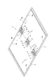
図1(a)、(b)は、本発明に係る多軸ヒンジ4、4、4を用いた電子機器の1例としてのノート型パソコン1を示す。このノート型パソコン1は、本発明に係る3個の多軸ヒンジ4、4、4によって互いに開閉可能なように連結された第1筐体2と第2筐体3とを備え、これら第1筐体2と第2筐体3のそれぞれの後部の左右個所と、中央箇所の3箇所において、本発明に係る多軸ヒンジ4、4,4により開閉可能に連結されて成るものである。左右2箇所だけではなく、中央箇所を含めて3箇所を本発明に係る多軸ヒンジ4、4、4により連結することによって、両筐体を安定的に連結できると共に、後述のタッチパネル式のフレキシブルなディスプレイシート5に凹凸が生じるのをより効果的に防止できる。図示した実施例においては、各多軸ヒンジ4の第1ブラケット56に設けた取付ネジ孔56e、56e(図3、図4参照)に取付ネジ6、6(図2参照)を挿入し、これらの取付ネジ6、6をノート型パソコン1の第1筐体2に設けたネジ孔(図では省略)にねじ込むことにより、各多軸ヒンジ4の第1ブラケット56を第1筐体2に取り付ける。同様に、各多軸ヒンジ4の第2ブラケット57に設けた取付ネジ孔57e、57e(図3、図4参照)には取付ネジ7、7(図2参照)を挿入し、これらの取付ネジ7、7をノート型パソコン1の第2筐体3に設けたネジ孔(図では省略)にねじ込むことにより、各多軸ヒンジ4の第2ブラケット57を第2筐体3に取り付ける。 1 (a) and 1 (b) show a notebook personal computer 1 as an example of an electronic device using the multi-axis hinges 4, 4 and 4 according to the present invention. The notebook personal computer 1 includes a first housing 2 and a second housing 3 connected so as to be openable and closable by the three multi-axis hinges 4, 4 and 4 according to the present invention. The rear left and right portions of the housing 2 and the second housing 3 and the central portion are connected to each other so as to be openable and closable by the multi-axis hinges 4, 4, and 4 according to the present invention. By connecting not only the two left and right locations but also three locations including the central location with the multi-axis hinges 4, 4 and 4 according to the present invention, both housings can be stably connected and the touch panel type flexible described later. It is possible to more effectively prevent unevenness from being generated on the display sheet 5. In the illustrated embodiment, mounting screws 6 and 6 (see FIG. 2) are inserted into the mounting screw holes 56e and 56e (see FIGS. 3 and 4) provided in the first bracket 56 of each multi-axis hinge 4, and these are inserted. The first bracket 56 of each multi-axis hinge 4 is attached to the first housing 2 by screwing the mounting screws 6 and 6 into the screw holes (omitted in the figure) provided in the first housing 2 of the notebook computer 1. .. Similarly, mounting screws 7 and 7 (see FIG. 2) are inserted into the mounting screw holes 57e and 57e (see FIGS. 3 and 4) provided in the second bracket 57 of each multi-axis hinge 4, and these mounting screws are inserted. The second bracket 57 of each multi-axis hinge 4 is attached to the second housing 3 by screwing 7 and 7 into the screw holes (omitted in the drawing) provided in the second housing 3 of the notebook computer 1.

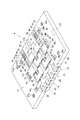
図示した実施例においては、上記の如く、多軸ヒンジ4、4、4により互いに開閉可能に連結されたノート型パソコン1の第1筐体2と第2筐体3との内面全体を、サイズの大きな1枚の液晶シートや有機EL等のタッチパネル式のフレキシブルなディスプレイシート5で連続的にカバーして、このディスプレイシート5の全体に動画その他の映像を表示することができるようになっている。また、必要に応じて、ディスプレイシート5の第1筐体2側の領域はキーボード面表示部5aとしてキーボード画像を表示してタッチパネル式のキーボードとして利用することもできる。その際、ディスプレイシート5の第2筐体3側の領域は、通常のノート型パソコンと同様にキーボード入力で操作される文書や画像等の映像表示部5bとして利用するようにする。これらの場合、第1筐体2と第2筐体3の内面全体を連続的にカバーする大サイズの1枚のフレキシブルなディスプレイシート5は、その中央部分を3本の取付ネジ8、8、8(図2参照)によって、前記3個の多軸ヒンジ4、4,4にそれぞれ固定するようになっている。図示した実施例において、1枚のフレキシブルなディスプレイシート5は前記3本の取付ネジ8、8、8のみによって前記3個の多軸ヒンジ4、4、4を介してノート型パソコン1の第1筐体2と第2筐体3に取り付けられ、ディスプレイシート5のそれ以外の部分は第1筐体2と第2筐体3に固定されることなく、第1筐体2と第2筐体3の内面上にフリー状態で保持されるようになっている。即ち、第1筐体2と第2筐体3の開閉操作に伴って、ディスプレイシート5の前記フリー状態の領域は第1筐体2と第2筐体3の内面に沿って数mm程度の範囲で摺動でき、第1筐体2や第2筐体3の内面からめくれ上がらないようになっている。即ち、例えば図2に示すように、第1筐体2の内面側の縁部から内方向へ向けて透明なプラスチック製の小さな押え爪2a、2aを設けて、この押え爪2a、2aによってディスプレイシート5の縁部が持ち上がらないように軽く押えるようにし、同様に、第2筐体3の内面側の縁部から内方向へ向けて透明なプラスチック製の小さな押え爪3a、3aを設けて、この押え爪3a、3aによってディスプレイシート5の縁部が持ち上がらないように軽く押えるようにすることが考えられる。但し、ディスプレイシート5の中央部以外の前記フリー状態の部分の保持手段は、これに限定されない。例えば、第1筺体2と第2筐体3の縁部の内側に保持用の溝部を設け、ディスプレイシート5の周端部を当該ディスプレイシートが摺動可能となるように保持し、第1筺体2と第2筐体3の開閉操作時におけるディスプレイシートの伸縮幅を吸収するように構成しても良い。 In the illustrated embodiment, as described above, the entire inner surface of the first housing 2 and the second housing 3 of the notebook computer 1 connected to each other by the multi-axis hinges 4, 4 and 4 so as to be openable and closable is sized. A large liquid crystal sheet or a touch panel type flexible display sheet 5 such as an organic EL can be continuously covered, and moving images and other images can be displayed on the entire display sheet 5. .. Further, if necessary, the area on the first housing 2 side of the display sheet 5 can be used as a touch panel type keyboard by displaying a keyboard image as a keyboard surface display unit 5a. At that time, the area on the second housing 3 side of the display sheet 5 is used as a video display unit 5b for documents, images, etc. operated by keyboard input in the same manner as a normal notebook computer. In these cases, one large-sized flexible display sheet 5 that continuously covers the entire inner surface of the first housing 2 and the second housing 3 has three mounting screws 8, 8 and its central portion. 8 (see FIG. 2) is used to fix the three multi-axis hinges 4, 4 and 4, respectively. In the illustrated embodiment, one flexible display sheet 5 is the first of the notebook personal computer 1 via the three multi-axis hinges 4, 4 and 4 only by the three mounting screws 8, 8 and 8. The first housing 2 and the second housing are attached to the housing 2 and the second housing 3, and the other parts of the display sheet 5 are not fixed to the first housing 2 and the second housing 3. It is designed to be held in a free state on the inner surface of 3. That is, with the opening / closing operation of the first housing 2 and the second housing 3, the free state region of the display sheet 5 is about several mm along the inner surfaces of the first housing 2 and the second housing 3. It can slide within a range and does not turn up from the inner surface of the first housing 2 or the second housing 3. That is, for example, as shown in FIG. 2, small transparent plastic presser claws 2a and 2a are provided inward from the edge on the inner surface side of the first housing 2, and the presser claws 2a and 2a are used for display. Lightly press the edge of the sheet 5 so that it does not lift up, and similarly, provide small transparent plastic presser claws 3a and 3a inward from the edge on the inner surface side of the second housing 3. It is conceivable that the presser claws 3a and 3a lightly press the edge of the display sheet 5 so as not to lift it. However, the means for holding the free state portion other than the central portion of the display sheet 5 is not limited to this. For example, a groove for holding is provided inside the edges of the first housing 2 and the second housing 3, and the peripheral end of the display sheet 5 is held so that the display sheet can slide, and the first housing is held. The display sheet may be configured to absorb the expansion / contraction width of the display sheet during the opening / closing operation of the second housing 3 and the second housing 3.

本発明に係る3個の多軸ヒンジ4、4、4は、同じ構成であるので、そのうちの1個のものを説明する。図2〜図24に示した実施例において、多軸ヒンジ4は、第1ブラケット56と第1取付部材17を介して前記ノート型パソコン1等の第1筐体2側に取り付けられる第1メインヒンジシャフト11と、同様に、第2ブラケット57と第2取付部材18を介して前記第2筐体3側に取り付けられる第2メインヒンジシャフト12とを有し、更に、複数の連結部材23、27、31により前記第1メインヒンジシャフト11と平行に保持される第1サブヒンジシャフト13と、同じく複数の連結部材24、28、32により前記第2メインヒンジシャフト12と平行に保持される第2サブヒンジシャフト14とを有している。前記第1サブヒンジシャフト13と第2サブヒンジシャフト14は、1個又は複数の連結部材33、51によって互いに平行に保持されるように構成される。 Since the three multi-axis hinges 4, 4, and 4 according to the present invention have the same configuration, one of them will be described. In the embodiment shown in FIGS. 2 to 24, the multi-axis hinge 4 is attached to the first housing 2 side of the notebook computer 1 or the like via the first bracket 56 and the first attachment member 17. Similarly, the hinge shaft 11 has a second main hinge shaft 12 attached to the second housing 3 side via a second bracket 57 and a second attachment member 18, and a plurality of connecting members 23, The first sub-hinge shaft 13 held in parallel with the first main hinge shaft 11 by 27, 31 and the second main hinge shaft 12 held in parallel with the second main hinge shaft 12 by a plurality of connecting members 24, 28, 32. It has two sub-hinge shafts 14. The first sub-hinge shaft 13 and the second sub-hinge shaft 14 are configured to be held in parallel with each other by one or a plurality of connecting members 33 and 51.

これらの第1メインヒンジシャフト11、第2メインヒンジシャフト12、第1サブヒンジシャフト13、第2サブヒンジシャフト14上には、ヒンジの開閉動作を実現するための回転制御手段15を構成する各種部材が装着され、当該回転制御手段15の一部として、前記第1筐体2と第2筐体3の開閉操作に伴う前記第1メインヒンジシャフト11と前記第2メインヒンジシャフト12のいずれか一方の回転動作を前記第1サブヒンジシャフト13及び第2サブヒンジシャフト14を介して他方に伝達するギア式の同期回転機構16が設けられる。前記回転制御手段15には、更に、ストッパー手段、フリクション機構36が含まれ、さらに吸込み機構39を加えることができる。 On the first main hinge shaft 11, the second main hinge shaft 12, the first sub-hinge shaft 13, and the second sub-hinge shaft 14, various rotation control means 15 for realizing the opening / closing operation of the hinge are configured. One of the first main hinge shaft 11 and the second main hinge shaft 12 accompanying the opening / closing operation of the first housing 2 and the second housing 3 as a part of the rotation control means 15 to which the member is mounted. A gear-type synchronous rotation mechanism 16 for transmitting one rotation operation to the other via the first sub-hinge shaft 13 and the second sub-hinge shaft 14 is provided. The rotation control means 15 further includes a stopper means and a friction mechanism 36, and a suction mechanism 39 can be further added.

そして、本発明に係る多軸ヒンジ4において特徴的なことは、内側両面に渡ってフレキシブルでタッチ操作可能なディスプレイシートを取り付けた第1筐体と第2筐体を開閉するために、第1筺体2と第2筐体3の両端部において、しかも前記ディスプレイシートの下側に位置して取り付けられる多軸ヒンジであって、前記第1筐体に取り付けた第1ブラケットと前記第2筐体に取り付けた第2ブラケットを互いに複数の連結部材で連結させた複数のヒンジシャフトを設け、この各ヒンジシャフトに互いに連携させて、或は独立させて少なくとも同期回転機構と、ストッパー手段と、フリクション機構を設け、前記第1筐体と第2筐体の閉成状態のときにはその内側に湾曲部が形成され、全開成状態のときには前記第1筐体と前記第2筐体と面一になるように構成したことである。また、他の形態においては、前記各ヒンジシャフトに互いに連携させて、或は独立させて少なくとも同期回転機構と、ストッパー手段と、フリクション機構と、及び又は吸込み機構を作用させ、前記第1筐体と第2筐体の閉成状態のときにはその内側に湾曲部が形成され、全開成状態のときには前記第1筐体と前記第2筐体と面一になるように構成したことである。以下、各部分の構成について具体的に説明する。 The multi-axis hinge 4 according to the present invention is characterized by the first opening and closing of the first housing and the second housing to which the flexible and touch-operable display sheet is attached to both inner surfaces. A multi-axis hinge that is attached at both ends of the housing 2 and the second housing 3 and is located below the display sheet, and is a first bracket and the second housing attached to the first housing. A plurality of hinge shafts are provided in which the second brackets attached to the above are connected to each other by a plurality of connecting members, and at least the synchronous rotation mechanism, the stopper means, and the friction mechanism are linked to each other or independently of each hinge shaft. When the first housing and the second housing are closed, a curved portion is formed inside the first housing and the second housing, and when the first housing and the second housing are fully opened, the first housing and the second housing are flush with each other. It is configured in. Further, in another form, at least the synchronous rotation mechanism, the stopper means, the friction mechanism, and / or the suction mechanism are acted on the hinge shafts in cooperation with each other or independently of the hinge shafts to act on the first housing. When the second housing is closed, a curved portion is formed inside the second housing, and when the second housing is fully opened, the first housing and the second housing are flush with each other. Hereinafter, the configuration of each part will be specifically described.

ノート型パソコン等の第1筐体2に取り付けられる第1ブラケット56と、第2筐体3に取り付けられる第2ブラケット57は、図3〜図6、図23に示すように、どちらも同一の構成を有し(図23では、第1ブラケット56を単品として示し、第2ブラケット57の対応部分の指示記号はカッコ書きで示す。以下、同様。)、主体部56a(57a)、固定ネジ孔56b〜56e(57b〜57e)、凹部56f〜56h(57f〜57h)を有している。この第1ブラケット56(第2ブラケット57)は、前記の如く、その固定ネジ孔56e、56e(57e、57e)に挿入される取付ネジ6、6(7、7)によって、ノート型パソコン等の第1筐体2(第2筐体3)に取り付けられる。第1ブラケット56(第2ブラケット57)の凹部56f(57f)には、第1取付部材17(第2取付部材18)のアーム部17e(18e)が嵌め入れられ、当該アーム部17e(18e)に設けた取付ネジ孔17f、17g(18f、18g)と、第1ブラケット56(第2ブラケット57)に設けた固定ネジ孔56b、56b(57b、57b)に、固定ネジ56i、56i(57i、57i。図5、図6参照)をねじ込むことにより、第1ブラケット56(第2ブラケット57)と第1取付部材17(第2取付部材18)とが固定される。第1ブラケット56(第2ブラケット57)の凹部56g(57g)には、第1補助取付部材29(30)のアーム部29c(30c)が嵌め入れられ、当該アーム部29c(30c)に設けた取付ネジ孔29d(30d)と、第1ブラケット56(第2ブラケット57)に設けた固定ネジ孔56c(57c)に、固定ネジ56j(57j。図5、図6参照)をねじ込むことにより、第1ブラケット56(第2ブラケット57)と第1補助取付部材29(30)とが固定される。同様に、第1ブラケット56(第2ブラケット57)の凹部56h(57h)には、スペーサー34(35)が嵌め入れられ、当該スペーサー34(35)に設けた取付ネジ孔34b(35b)と、第1ブラケット56(第2ブラケット57)に設けた固定ネジ孔56d(57d)に、固定ネジ56k(57k。図5、図6参照)をねじ込むことにより、第1ブラケット56(第2ブラケット57)とスペーサー34(35)とが固定され、第1ブラケット56(第2ブラケット57)の凹部56h(57h)が穴埋めされて平坦化される。尚、第1ブラケット56(第2ブラケット57)に、使用目的のない凹部56h(57h)を一旦形成し、その後これをスペーサー34(35)で穴埋めする理由は、第1ブラケット56と第2ブラケット57を同一形状とすることにより、製造コストを低減化するためである。即ち、第1補助取付部材29(30)を取り付けるための凹部56g(57g)を設けただけでは、第1ブラケット56と第2ブラケット57は鏡像対称となり、同一形状ではないため、それぞれ個別に製造する必要があり、それによるコスト高を回避するためである。 As shown in FIGS. 3 to 6 and 23, the first bracket 56 attached to the first housing 2 of a notebook computer or the like and the second bracket 57 attached to the second housing 3 are both the same. It has a configuration (in FIG. 23, the first bracket 56 is shown as a single item, and the indicator symbols of the corresponding parts of the second bracket 57 are shown in parentheses; the same applies hereinafter), the main body portion 56a (57a), and the fixing screw hole. It has 56b to 56e (57b to 57e) and recesses 56f to 56h (57f to 57h). As described above, the first bracket 56 (second bracket 57) is made of a notebook computer or the like by means of mounting screws 6, 6 (7, 7) inserted into the fixing screw holes 56e, 56e (57e, 57e). It is attached to the first housing 2 (second housing 3). The arm portion 17e (18e) of the first mounting member 17 (second mounting member 18) is fitted into the recess 56f (57f) of the first bracket 56 (second bracket 57), and the arm portion 17e (18e) is fitted. In the mounting screw holes 17f, 17g (18f, 18g) provided in the first bracket 56 (second bracket 57) and the fixing screw holes 56b, 56b (57b, 57b) provided in the first bracket 56 (second bracket 57), the fixing screws 56i, 56i (57i, By screwing 57i (see FIGS. 5 and 6), the first bracket 56 (second bracket 57) and the first mounting member 17 (second mounting member 18) are fixed. The arm portion 29c (30c) of the first auxiliary mounting member 29 (30) was fitted into the recess 56g (57g) of the first bracket 56 (second bracket 57) and provided in the arm portion 29c (30c). By screwing the fixing screw 56j (57j, see FIGS. 5 and 6) into the mounting screw hole 29d (30d) and the fixing screw hole 56c (57c) provided in the first bracket 56 (second bracket 57), the first The 1 bracket 56 (second bracket 57) and the first auxiliary mounting member 29 (30) are fixed. Similarly, the spacer 34 (35) is fitted into the recess 56h (57h) of the first bracket 56 (second bracket 57), and the mounting screw holes 34b (35b) provided in the spacer 34 (35) are By screwing the fixing screw 56k (57k, see FIGS. 5 and 6) into the fixing screw hole 56d (57d) provided in the first bracket 56 (second bracket 57), the first bracket 56 (second bracket 57) And the spacer 34 (35) are fixed, and the recesses 56h (57h) of the first bracket 56 (second bracket 57) are filled in and flattened. The reason why the recess 56h (57h ) having no purpose of use is once formed in the first bracket 56 (second bracket 57) and then filled with the spacer 34 (35) is because the first bracket 56 and the second bracket are used. This is to reduce the manufacturing cost by making the 57s have the same shape. That is, if only the recess 56 g (57 g) for mounting the first auxiliary mounting member 29 (30) is provided, the first bracket 56 and the second bracket 57 are mirror image symmetric and do not have the same shape. This is to avoid the high cost associated with it.

第1メインヒンジシャフト11(図7に第1メインヒンジシャフト11を単品として示す。第2メインヒンジシャフト12も同一構成であるので、その指示記号を第1メインヒンジシャフト11の指示記号の後に括弧書きにより併記する。)は、図示する如く構成され、頭部11a(12a)と、円形軸部11b(12b)と、異形軸部11c(12c)と、雄ネジ部11d(12d)とを有する。 The first main hinge shaft 11 (the first main hinge shaft 11 is shown as a single item in FIG. 7. Since the second main hinge shaft 12 also has the same configuration, the instruction symbol is shown in parentheses after the instruction symbol of the first main hinge shaft 11. (Also described by writing) is configured as shown in the drawing, and has a head portion 11a (12a), a circular shaft portion 11b (12b), a deformed shaft portion 11c (12c), and a male screw portion 11d (12d). ..

第1メインヒンジシャフト11(第2メインヒンジシャフト12)は、図3、図5、図6に示す如く、連結部材31(32)、第1補助取付部材29(30)、もう1つ別種の連結部材27(28)、第1取付部材17(18)、更に別種の連結部材23(24)、第1フリクションワッシャー37(38)、第1カムディスク40(41)、第1カムフォロワー42(43)、第1弾性手段44a(44b)の皿バネ45、45(46、46)、ワッシャー47(48)に順次挿通され、先端の雄ネジ部11d(12d)に締付けナット49(50)が螺着される。これによって、第1メインヒンジシャフト11(第2メインヒンジシャフト12)の軸部に、前記各構成部材が装着される。その場合、第1メインヒンジシャフト11(第2メインヒンジシャフト12)の円形軸部11b(12b)は、前記連結部材31(32)の第1円形軸孔31d(32d)(図15参照)、第1補助取付部材29(30)の円形軸孔29b(30b)(図14参照)、連結部材27(28)の第1円形軸孔27d(28d)(図11参照)、連結部材23(24)の第1円形軸孔23c(24c)(図12参照)に挿通されることにより、これらの各構成部材は円形軸部11b(12b)の軸中心に回転可能に装着される。第1メインヒンジシャフト11(12)の異形軸部11c(12c)には、第1取付部材17(18)、連結部材23(24)、第1フリクションワッシャー37(38)、第1カムディスク40(41)、第1カムフォロワー42(43)、皿バネ45、45(46、46)、ワッシャー47(48)が装着される。その場合、第1メインヒンジシャフト11(12)の異形軸部11c(12c)は、第1取付部材17(18)の異形軸孔17b(18b)(図9参照)、第1フリクションワッシャー37(38)の異形軸孔37b(38b)(図18参照)、第1カムフォロワー42(43)の異形軸孔42b(43b)(図20参照)、ワッシャー47(48)の異形軸孔47b(48b)(図5、6参照)に挿通され、これらの各構成部材が第1メインヒンジシャフト11(12)の異形軸部11c(12c)の軸中心の回転を拘束された状態で装着される。 The first main hinge shaft 11 (second main hinge shaft 12) includes a connecting member 31 (32), a first auxiliary mounting member 29 (30), and another type, as shown in FIGS. 3, 5, and 6. Connecting member 27 (28), first mounting member 17 (18), another type of connecting member 23 (24), first friction washer 37 (38), first cam disc 40 (41), first cam follower 42 ( 43), the disc springs 45, 45 (46, 46) of the first elastic means 44a (44b), and the washer 47 (48) are sequentially inserted, and the tightening nut 49 (50) is attached to the male screw portion 11d (12d) at the tip. It is screwed. As a result, the respective constituent members are mounted on the shaft portion of the first main hinge shaft 11 (second main hinge shaft 12). In that case, the circular shaft portion 11b (12b) of the first main hinge shaft 11 (second main hinge shaft 12) has the first circular shaft hole 31d (32d) of the connecting member 31 (32) (see FIG. 15). The circular shaft hole 29b (30b) of the first auxiliary mounting member 29 (30) (see FIG. 14), the first circular shaft hole 27d (28d) of the connecting member 27 (28) (see FIG. 11), and the connecting member 23 (24). ) Is inserted into the first circular shaft hole 23c (24c) (see FIG. 12), so that each of these constituent members is rotatably mounted on the shaft center of the circular shaft portion 11b (12b). The deformed shaft portion 11c (12c) of the first main hinge shaft 11 (12) has a first mounting member 17 (18), a connecting member 23 (24), a first friction washer 37 (38), and a first cam disc 40. (41), the first cam follower 42 (43), the disc springs 45, 45 (46, 46), and the washer 47 (48) are attached. In that case, the deformed shaft portion 11c (12c) of the first main hinge shaft 11 (12) is the deformed shaft hole 17b (18b) (see FIG. 9) of the first mounting member 17 (18), and the first friction washer 37 (see FIG. 9). Deformed shaft hole 37b (38b) of 38) (see FIG. 18), deformed shaft hole 42b ( 43b ) of the first cam follower 42 (43) (see FIG. 20), and deformed shaft hole 47b (48b) of washer 47 (48). ) (See FIGS. 5 and 6), and each of these constituent members is mounted in a state where the rotation of the shaft center of the deformed shaft portion 11c (12c) of the first main hinge shaft 11 (12) is restricted.

第1サブヒンジシャフト13(第2サブヒンジシャフト14)は、図3、図5、図6に示す如く、その円形軸部13b(14b)が、連結部材31(32)の第2円形軸孔31e(第2円形軸孔32e)(図15参照)、それとは別種の連結部材33の第1円形軸孔33c(第2円形軸孔33e)(図16参照)、更に別種の前記連結部材27(28)の第円形軸孔27e(第2円形軸孔28e)(図11参照)、旋回ブロック21の第1円形軸孔21d(第2円形軸孔21e)、更に別種の前記連結部材23(24)の第2円形軸孔23e(第2円形軸孔24e)(図12参照)、更に別種の連結部材51の第1円形軸孔51c(第2円形軸孔51e)(図17参照)に順次挿通された後、第1サブヒンジシャフト13(第2サブヒンジシャフト14)の先端側円形軸部13d(14d)を第1サブヒンジシャフト13(第2サブヒンジシャフト14)の先端側円形軸部13d(14d)を第1軸端取付部材52(第2軸端取付部材53)(図21参照)の円形軸孔52c(53c)に挿入し、図5、図6に示した止めネジ54(55)を第1軸端取付部材52(第2軸端取付部材53)のネジ孔52d(53d)にねじ込むことによって、当該止めネジ54(55)の側面が第1サブヒンジシャフト13(第2サブヒンジシャフト14)の止めネジ係止溝13c(14c)に係合して、第1サブヒンジシャフト13(第2サブヒンジシャフト14)の軸上に前記各構成部材が抜け落ちることなく装着される。尚、第1サブヒンジシャフト13(第2サブヒンジシャフト14)の軸部は円形軸部13b(14b)だけであるため、この軸部上に装着された前記各構成部材は、第1サブヒンジシャフト13(第2サブヒンジシャフト14)の軸部に対して回転を拘束されることなく、いずれも回転可能なように保持される。 As shown in FIGS. 3, 5, and 6, the first sub-hinge shaft 13 (second sub-hinge shaft 14) has a circular shaft portion 13b (14b) of which is a second circular shaft hole of the connecting member 31 (32). 31e (second circular shaft hole 32e ) (see FIG. 15), a first circular shaft hole 33c (second circular shaft hole 33e) (see FIG. 16) of a connecting member 33 of a different type, and the connecting member 27 of a different type. The first circular shaft hole 27e (second circular shaft hole 28e) (see FIG. 11) of (28), the first circular shaft hole 21d (second circular shaft hole 21e) of the swivel block 21, and another type of the connecting member 23. The second circular shaft hole 23e (second circular shaft hole 24e) (see FIG. 12) of (24), and the first circular shaft hole 51c (second circular shaft hole 51e) of another type of connecting member 51 (see FIG. 17). The tip-side circular shaft portion 13d (14d) of the first sub-hinge shaft 13 (second sub-hinge shaft 14) is changed to the tip-side circular shaft portion of the first sub-hinge shaft 13 (second sub-hinge shaft 14). The shaft portion 13d (14d) is inserted into the circular shaft hole 52c (53c) of the first shaft end mounting member 52 (second shaft end mounting member 53) (see FIG. 21), and the set screw shown in FIGS. 5 and 6 is inserted. By screwing 54 (55) into the screw holes 52d (53d) of the first shaft end mounting member 52 (second shaft end mounting member 53), the side surface of the set screw 54 (55) becomes the first sub-hinge shaft 13 ( Engage with the set screw locking groove 13c (14c) of the second sub-hinge shaft 14) and mount the constituent members on the shaft of the first sub-hinge shaft 13 (second sub-hinge shaft 14) without falling off. Will be done. Since the shaft portion of the first sub-hinge shaft 13 (second sub-hinge shaft 14) is only the circular shaft portion 13b (14b), each of the constituent members mounted on the shaft portion is the first sub-hinge. Rotation is not restricted with respect to the shaft portion of the shaft 13 (second sub-hinge shaft 14), and both are held so as to be rotatable.

前記の如く、第1メインヒンジシャフト11(第2メインヒンジシャフト12)と第1サブヒンジシャフト13(第2サブヒンジシャフト14)の軸上に前記の各構成部材を装着する過程において、第1両面傘歯型中間ギア19(第2両面傘歯型中間ギア20)を連結部材27(28)の中間ギア収容凹部27h(28h)内に回転可能なように収容し(図5、図6参照)、更にこの第1両面傘歯型中間ギア19(第2両面傘歯型中間ギア20)の外周面と前記連結部材23(24)の係合凸部23g(24g)との間に介装されるようにスペーサー25(26)を保持させる。更に、第3両面傘歯型中間ギア22を旋回ブロック21の中間ギア収容凹部21h内に回転可能なように収容し、この第3両面傘歯型中間ギア22の外周面を前記連結部材51の当接凹部51gとの間に保持させる。このように、これらの第1両面傘歯型中間ギア19(20)、第3両面傘歯型中間ギア22及びスペーサー25(26)は、第1メインヒンジシャフト11(第2メインヒンジシャフト12)や第1サブヒンジシャフト13(第2サブヒンジシャフト14)の軸上に直接的に装着されるのではなく、他の構成部材を介して間接的に保持されることになる。 As described above, in the process of mounting each of the above components on the shafts of the first main hinge shaft 11 (second main hinge shaft 12) and the first sub-hinge shaft 13 (second sub-hinge shaft 14), the first The double-sided hinged intermediate gear 19 (second double-sided hinged intermediate gear 20) is rotatably accommodated in the intermediate gear accommodating recess 27h (28h) of the connecting member 27 (28) (see FIGS. 5 and 6). ), Further intervening between the outer peripheral surface of the first double-sided hinged intermediate gear 19 (second double-sided hinged intermediate gear 20) and the engaging convex portion 23 g (24 g) of the connecting member 23 (24). The spacer 25 (26) is held so as to be. Further, the third double-sided bevel gear type intermediate gear 22 is housed in the intermediate gear accommodating recess 21h of the swivel block 21 so as to be rotatable, and the outer peripheral surface of the third double-sided bevel tooth type intermediate gear 22 is accommodated in the connecting member 51. It is held between the contact recess 51g and the contact recess 51g. As described above, the first double-sided bevel gear type intermediate gear 19 (20), the third double-sided bevel tooth type intermediate gear 22 and the spacer 25 (26) are the first main hinge shaft 11 (second main hinge shaft 12). And the first sub-hinge shaft 13 (second sub-hinge shaft 14) is not directly mounted on the shaft, but is indirectly held via other constituent members.

以上のようにして組み立てられた本発明に係る多軸ヒンジ4は、第1筐体2及び第2筐体3の全開成状態のときには、図3に示すように内面が平坦な外観を呈し、図2に示すように第1筐体2及び第2筐体3と面一の内面が形成される。また、閉成状態のときには、図4に示すようにその内側に湾曲部4aが形成され、その湾曲率が所定値以下とならないように規制される。 The multi-axis hinge 4 according to the present invention assembled as described above exhibits a flat inner surface as shown in FIG. 3 when the first housing 2 and the second housing 3 are fully opened. As shown in FIG. 2, an inner surface flush with the first housing 2 and the second housing 3 is formed. Further, in the closed state, as shown in FIG. 4, a curved portion 4a is formed inside the curved portion 4a, and the bending rate is regulated so as not to be less than a predetermined value.

以下、前記各構成部材によって構築される本発明に係る多軸ヒンジ4における各部の構成について説明する。図5及び図6に示す如く、本発明に係る多軸ヒンジ4は、回転制御手段15を備え、この回転制御手段15は、同期回転機構16と、ストッパー手段33oと、フリクション機構36と、吸込み機構39とから構成される。 Hereinafter, the configuration of each part of the multi-axis hinge 4 according to the present invention constructed by each of the constituent members will be described. As shown in FIGS. 5 and 6, the multi-axis hinge 4 according to the present invention includes a rotation control means 15, and the rotation control means 15 includes a synchronous rotation mechanism 16, a stopper means 33o, a friction mechanism 36, and a suction mechanism. It is composed of a mechanism 39.

これらのうち、まず同期回転機構16は、ギア式であって、その主要な構成要素として、前記第1及び第2メインヒンジシャフト11、12に対してそれぞれ回転を拘束した状態で取り付けられた前記第1及び第2取付部材17、18と、前記第1及び第2サブヒンジシャフト13、14がそれぞれ回転可能に挿通された旋回ブロック21と、前記第1取付部材17の回転を前記旋回ブロック21に伝達する第1両面傘歯型中間ギア19と、前記第2取付部材18の回転を前記旋回ブロック21に伝達する第2両面傘歯型中間ギア20とを有し、さらに、前記旋回ブロック21に回転可能に装着された第3両面傘歯型中間ギア22と、前記第1メインヒンジシャフト11(第2メインヒンジシャフト12)及び第1サブヒンジシャフト13(第2サブヒンジシャフト14)がそれぞれ回転可能に挿通され、前記第3両面傘歯型中間ギア22と噛合する傘歯型ギアを有する連結部材23(24)とを有する。 Of these, first, the synchronous rotation mechanism 16 is a gear type, and as its main component, the synchronous rotation mechanism 16 is attached to the first and second main hinge shafts 11 and 12, respectively, in a state of restraining rotation. The swivel block 21 into which the first and second mounting members 17 and 18, the first and second sub-hinge shafts 13 and 14, respectively are rotatably inserted, and the swivel block 21 rotates the first mounting member 17. It has a first double-sided captooth type intermediate gear 19 that transmits the rotation of the second mounting member 18 to the swivel block 21, and a second double-sided captooth type intermediate gear 20 that transmits the rotation of the second mounting member 18 to the swivel block 21. The first main hinge shaft 11 (second main hinge shaft 12) and the first sub hinge shaft 13 (second sub hinge shaft 14) are respectively rotatably mounted on the third double-sided umbrella tooth type intermediate gear 22. It has a connecting member 23 (24) that is rotatably inserted and has a bevel gear that meshes with the third double-sided bead intermediate gear 22.

前記第1及び第2取付部材17、18(両者の構成は同一であるので、以下では第1取付部材17について説明し、第2取付部材18については、その指示記号を第1取付部材17の指示記号の後に括弧書きで併記することにより、重複説明を省略する。図5、図6、図9参照。この点は、他の部材についても同様とする。)は、円筒主体部17a(18a)と、異形軸孔17b(18b)と、傘歯型駆動ギア17c、17d(18c、18d)と、アーム部17e(18e)と、取付ネジ孔17f、17g(18f、18g)とを有し、その異形軸孔17b(18b)に前記第1メインヒンジシャフト11(12)の異形軸部11c(12c)を挿通することにより、前記第1ブラケット56(57)の回転操作と共に、第1メインヒンジシャフト11(12)も一緒に回転するようになっている。この第1取付部材17(18)の円筒主体部17a(18a)の軸端面には、第1メインヒンジシャフト11(12)を中心軸とする傘歯型駆動ギア17c、17d(18c、18d)が形成されている。このうち傘歯型駆動ギア17c(18c)は、後述する第1両面傘歯型中間ギア19(20)の傘歯型従動ギア19b(20b)と噛み合うようになっている。第1取付部材17(18)のもう一方の傘歯型駆動ギア17d(18d)は、製造コスト節減のためにこれらの第1取付部材17と第2取付部材18とを完全に同一形状、同一サイズの部材として作製し、兼用するようにしたために設けられているものであり、図示した実施例における組み立て状態においては、これが噛み合うべき相手歯車は存在しない。 The first and second mounting members 17 and 18 (since the configurations of both are the same, the first mounting member 17 will be described below, and for the second mounting member 18, the instruction symbol thereof is given to the first mounting member 17. Duplicate explanations are omitted by writing them in parentheses after the indicator symbols. See FIGS. 5, 6, and 9. This point is the same for other members.) Is the cylindrical main body portion 17a (18a). ), Deformed shaft holes 17b (18b), hinged tooth type drive gears 17c, 17d (18c, 18d), arm portions 17e (18e), and mounting screw holes 17f, 17g (18f, 18g). By inserting the deformed shaft portion 11c (12c) of the first main hinge shaft 11 (12) into the deformed shaft hole 17b (18b), the first main bracket 56 (57) is rotated and the first main is operated. The hinge shaft 11 (12) is also designed to rotate together. Umbrella tooth type drive gears 17c, 17d (18c, 18d) centered on the first main hinge shaft 11 (12) are provided on the shaft end faces of the cylindrical main body portion 17a (18a) of the first mounting member 17 (18). Is formed. Of these, the bevel tooth type drive gear 17c (18c) meshes with the umbrella tooth type driven gear 19b (20b) of the first double-sided bevel tooth type intermediate gear 19 (20) described later. The other bevel tooth type drive gear 17d (18d) of the first mounting member 17 (18) has the same shape and the same shape as the first mounting member 17 and the second mounting member 18 in order to reduce the manufacturing cost. It is provided because it is manufactured as a member of a size and is also used, and in the assembled state in the illustrated embodiment, there is no mating gear to which this should mesh.

前記旋回ブロック21は、図示(図5、図6、図11参照)する如く、主体部21aと、第1円筒軸部21bと、第2円筒軸部21cと、第1円形軸孔21dと、第2円形軸孔21eと、第1傘歯型従動ギア21fと、第2傘歯型従動ギア21gと、中間ギア収容凹部21hと、連結部材係止凸部21iと、ストッパー凹部21j、21kと、中間ギア収容凹面21lとを有し、その第1円形軸孔21dには第1サブヒンジシャフト13が回転可能に挿通され、もう一方の第2円形軸孔21eには第2サブヒンジシャフト14が回転可能に挿通されるようになっている。この旋回ブロック21の前記第1傘歯型従動ギア21fは、次に説明する第1両面傘歯型中間ギア19(図3、5、6、10参照)の傘歯型従動ギア19bと噛み合い、旋回ブロック21の前記第2傘歯型従動ギア21gは、次に説明する第2両面傘歯型中間ギア20(図3等参照)の傘歯型従動ギア20bと噛み合うようになっている。また、旋回ブロック21の前記中間ギア収容凹部21hと中間ギア収容凹面21lとによって形成される空間には、後述する第3両面傘歯型中間ギア22(図5、図6、図10参照)が回転可能に収容され、前記連結部材係止凸部21iは、後述する連結部材33の円弧状凹部33nに当接、係合せしめられるようになっている。尚、旋回ブロック21の前記ストッパー凹部21j、21kは、製造コスト節減のためこの旋回ブロック21と完全に同一形状、同一サイズの部材として作製、使用される後述の連結部材27、28において必要とされる構成要素であり、旋回ブロック21として用いられるときには、特別の機能は有さない。即ち、後述の連結部材27、28のストッパー凹部27j、27k(28j、28k)が、後述する連結部材33のストッパー凸部33m、33nと共働して、連結部材27、28の回転角度を所定範囲内に規制するストッパー機能を生じさせるためのものであり、旋回ブロック21として用いられるときには、それらのストッパー凹部21j、21kは特別の機能は有さない。 As shown in the drawings (see FIGS. 5, 6, and 11), the swivel block 21 includes a main body portion 21a, a first cylindrical shaft portion 21b, a second cylindrical shaft portion 21c, a first circular shaft hole 21d, and the like. A second circular shaft hole 21e, a first umbrella tooth type driven gear 21f, a second umbrella tooth type driven gear 21g, an intermediate gear accommodating recess 21h, a connecting member locking convex portion 21i, and stopper recesses 21j and 21k. The first sub-hinge shaft 13 is rotatably inserted into the first circular shaft hole 21d, and the second sub-hinge shaft 14 is rotatably inserted into the other second circular shaft hole 21e. Is rotatably inserted. The first bevel tooth type driven gear 21f of the swivel block 21 meshes with the bevel tooth type driven gear 19b of the first double-sided bevel tooth type intermediate gear 19 (see FIGS. 3, 5, 6 and 10) described below. The second bevel tooth type driven gear 21g of the swivel block 21 meshes with the bevel tooth type driven gear 20b of the second double-sided bevel tooth type intermediate gear 20 (see FIG. 3 and the like) described below. Further, in the space formed by the intermediate gear accommodating recess 21h and the intermediate gear accommodating concave surface 21l of the swivel block 21, a third double-sided umbrella tooth type intermediate gear 22 (see FIGS. 5, 6, and 10) described later is provided. It is rotatably accommodated, and the connecting member locking convex portion 21i is adapted to abut and engage with the arcuate concave portion 33n of the connecting member 33, which will be described later. The stopper recesses 21j and 21k of the swivel block 21 are required in the connecting members 27 and 28 described later, which are manufactured and used as members having exactly the same shape and size as the swivel block 21 in order to reduce manufacturing costs. When used as a swivel block 21, it does not have any special function. That is, the stopper recesses 27j, 27k (28j, 28k) of the connecting members 27, 28 described later cooperate with the stopper protrusions 33m, 33n of the connecting member 33 described later to determine the rotation angle of the connecting members 27, 28. The purpose is to generate a stopper function that regulates within the range, and when used as the swivel block 21, the stopper recesses 21j and 21k do not have a special function.

前記第1両面傘歯型中間ギア19(第2両面傘歯型中間ギア20)は、円盤状主体部19a(20a)と、傘歯型従動ギア19b、19c(20b、20c)とを有し、前記第1取付部材17(18)の前記傘歯型駆動ギア17c(18c)の回転を前記旋回ブロック21の第1傘歯型従動ギア21f(第2傘歯型従動ギア21g)に伝達するようになっている。この第1両面傘歯型中間ギア19(第2両面傘歯型中間ギア20)の円盤状主体部19a(20a)は、連結部材27(28)の中間ギア収容凹部27h(28h)と中間ギア収容凹面27l(28l)とによって形成される空間に回転可能に収容されるようになっている。その場合、第1両面傘歯型中間ギア19(20)は、前記空間内において、前記第1メインヒンジシャフト11(12)と直交する軸を中心に回転可能に保持される。この点は、前記旋回ブロック21に対する第3両面傘歯型中間ギア22の取付状態も同様である。連結部材27(28)の中間ギア収容凹部27h(28h)内に収容された第1両面傘歯型中間ギア19(20)の脱落やブレを防止し、かつ、この第1両面傘歯型中間ギア19(20)の外周面の周囲に形成される空隙を穴埋めするために、第1両面傘歯型中間ギア19(20)の外周面の一部にスペーサー25(26)を摺接させた状態で、第1両面傘歯型中間ギア19(20)を一定位置で回転可能に保持するようにする。第1両面傘歯型中間ギア19(20)の一方の傘歯型従動ギア19b(20b)は前記第1取付部材17(第2取付部材18)の前記傘歯型駆動ギア17c(18c)と噛み合わせられ、第1両面傘歯型中間ギア19(20)のもう一方の傘歯型従動ギア19c(20c)は前記旋回ブロック21の前記第1傘歯型従動ギア21f(21g)と噛み合わせられる。 The first double-sided bevel tooth type intermediate gear 19 (second double-sided bevel tooth type intermediate gear 20) has a disk-shaped main body portion 19a (20a) and a bevel tooth type driven gear 19b, 19c (20b, 20c). , The rotation of the bevel gear type drive gear 17c (18c) of the first mounting member 17 (18) is transmitted to the first bevel tooth type driven gear 21f (second bevel tooth type driven gear 21g) of the turning block 21. It has become like. The disk-shaped main body portion 19a (20a) of the first double-sided bevel tooth type intermediate gear 19 (second double-sided bevel tooth type intermediate gear 20) is formed between the intermediate gear accommodating recess 27h (28h) of the connecting member 27 (28) and the intermediate gear. It is rotatably accommodated in the space formed by the accommodating concave surfaces 27l (28l). In that case, the first double-sided bevel tooth type intermediate gear 19 (20) is rotatably held in the space about an axis orthogonal to the first main hinge shaft 11 (12). This point is the same in the mounted state of the third double-sided umbrella tooth type intermediate gear 22 with respect to the swivel block 21. The first double-sided bevel gear type intermediate gear 19 (20) housed in the intermediate gear accommodating recess 27h (28h) of the connecting member 27 (28) is prevented from falling off or shaken, and the first double-sided bevel tooth type intermediate In order to fill the gap formed around the outer peripheral surface of the gear 19 (20), the spacer 25 (26) is slidably contacted with a part of the outer peripheral surface of the first double-sided bevel tooth type intermediate gear 19 (20). In this state, the first double-sided bevel tooth type intermediate gear 19 (20) is rotatably held at a fixed position. One of the bevel tooth type driven gears 19b (20b) of the first double-sided bevel tooth type intermediate gear 19 (20) is the same as the bevel tooth type drive gear 17c (18c) of the first mounting member 17 (second mounting member 18). The other bevel tooth type driven gear 19c (20c) of the first double-sided bevel tooth type intermediate gear 19 (20) is meshed with the first bevel tooth type driven gear 21f (21 g) of the turning block 21. Beveled.

連結部材27(28)は、本実施例の場合、前述のように前記旋回ブロック21と完全に同一形状、同一サイズの部材として作製された構成要素であり、図示(図5、図6、図11参照)する如く、主体部27a(28a)と、第1円筒軸部27b(28b)と、第2円筒軸部27c(28c)と、第1円形軸孔27d(28d)と、第2円形軸孔27e(28e)と、第1傘歯型従動ギア27f(28f)と、第2傘歯型従動ギア27g(28g)と、中間ギア収容凹部27h(28h)と、連結部材係止凸部27i(28i)と、ストッパー凹部27j、27k(28j、28k)と、中間ギア収容凹面27l(28l)とを有し、その第1円形軸孔27d(28d)には第1メインヒンジシャフト11(12)が回転可能に挿通され、もう一方の第2円形軸孔27e(28e)には第1サブヒンジシャフト13(14)が回転可能に挿通されるようになっている。連結部材27(28)の中間ギア収容凹部27h(28h)には、前記の如く第1両面傘歯型中間ギア19(20)が回転可能なように収容される。連結部材27(28)の前記第2円筒軸部27c(28c)の外周面に設けたストッパー凹部27k(28k)には、後述する連結部材33のストッパー凸部33m(33n)が嵌入して、両者が係合すること(図25参照)により、後述するストッパー手段33oが構成されるようになっている。連結部材27(28)の前記連結部材係止凸部27i(28i)は、連結部材31(32)の円弧状凹部31h(32h)に収容される。連結部材27(28)の前記第1傘歯型従動ギア27f(28f)と第2傘歯型従動ギア27g(28g)は、図示した組立て状態においては特別の機能は有さない。 In the case of this embodiment, the connecting member 27 (28) is a component manufactured as a member having completely the same shape and the same size as the swivel block 21 as described above, and is shown (FIGS. 5, 6, 6). 11), the main body portion 27a (28a), the first cylindrical shaft portion 27b (28b), the second cylindrical shaft portion 27c (28c), the first circular shaft hole 27d (28d), and the second circular shaft portion 27d (28d). Shaft hole 27e (28e), first umbrella tooth type driven gear 27f (28f), second umbrella tooth type driven gear 27g (28g), intermediate gear accommodating recess 27h (28h), connecting member locking convex portion It has 27i (28i), stopper recesses 27j, 27k (28j, 28k), and an intermediate gear accommodating concave surface 27l (28l), and the first circular shaft hole 27d (28d) has a first main hinge shaft 11 ( 12) is rotatably inserted, and the first sub-hinge shaft 13 (14) is rotatably inserted into the other second circular shaft hole 27e (28e). As described above, the first double-sided umbrella tooth type intermediate gear 19 (20) is rotatably accommodated in the intermediate gear accommodating recess 27h (28h) of the connecting member 27 (28). The stopper convex portion 33m (33n) of the connecting member 33, which will be described later, is fitted into the stopper concave portion 27k (28k) provided on the outer peripheral surface of the second cylindrical shaft portion 27c (28c) of the connecting member 27 (28). By engaging the two (see FIG. 25), the stopper means 33o described later is configured. The connecting member locking convex portion 27i (28i) of the connecting member 27 (28) is housed in the arcuate concave portion 31h (32h) of the connecting member 31 (32). The first umbrella tooth type driven gear 27f (28f) and the second umbrella tooth type driven gear 27g (28g) of the connecting member 27 (28) do not have a special function in the illustrated assembled state.

スペーサー25(26)は、その主体部25a(26a)の両端に円弧状凹部25b、25c(26b、26c)を有すると共に、両側面に円弧状凹部25d、25e(26d、26e)を有している。その一端側の円弧状凹部25b(26b)は前記第1両面傘歯型中間ギア19(第2両面傘歯型中間ギア20)の外周面に摺接し、他端側の円弧状凹部25c(26c)は後述する連結部材23(24)のスペーサー係止凸部23g(24g)に当接した状態で設けられるようになっている。また、スペーサー25(26)の一方の側面の円弧状凹部25d(26d)は前記第1取付部材17(18)の円筒主体部17a(18a)の外周面に当接すると共に、スペーサー25(26)のもう一方の側面の円弧状凹部25e(26e)は前記旋回ブロック21の第1円筒軸部21b(21c)の外周面に当接する状態で設けられるようになっている。 The spacer 25 (26) has arcuate recesses 25b, 25c (26b, 26c) at both ends of the main body 25a (26a), and has arcuate recesses 25d, 25e (26d, 26e) on both side surfaces. There is. The arcuate recess 25b (26b) on one end side is in sliding contact with the outer peripheral surface of the first double-sided bevel tooth type intermediate gear 19 (second double-sided bevel tooth type intermediate gear 20), and the arcuate recess 25c (26c) on the other end side is in sliding contact with the outer peripheral surface. ) Is provided in a state of being in contact with the spacer locking convex portion 23g (24g) of the connecting member 23 (24) described later. Further, the arcuate recess 25d (26d) on one side surface of the spacer 25 (26) abuts on the outer peripheral surface of the cylindrical main body portion 17a (18a) of the first mounting member 17 (18), and the spacer 25 (26) The arcuate recess 25e (26e) on the other side surface of the swivel block 21 is provided in contact with the outer peripheral surface of the first cylindrical shaft portion 21b (21c) of the swivel block 21.

したがって、前記第1、第2両面傘歯型中間ギア19、20及びスペーサー25、26は、第1、第2メインヒンジシャフト11、12、第1、第2サブヒンジシャフト13、14や第1、第2ブラケット56、57等に直接的に取り付けられるのではなく、第1、第2メインヒンジシャフト11、12等に直接的に取り付けられた他の部材によって間接的に支承されている点が、それらの他の部材とは相違している。 Therefore, the first and second double-sided bevel tooth type intermediate gears 19 and 20 and the spacers 25 and 26 are the first and second main hinge shafts 11, 12, the first and second sub-hinge shafts 13, 14 and the first. , It is not directly attached to the second brackets 56, 57, etc., but is indirectly supported by other members directly attached to the first, second main hinge shafts 11, 12, etc. , Different from those other members.

連結部材33(図5、6、16参照)は、主体部33aと、第1円環軸部33bと、第2円環軸部33cと、第1円形軸孔33dと、第2円形軸孔33eと、第1隔壁33fと、第2隔壁33gと、円弧状凹部33h〜33lと、ストッパー凸部33m、33nとを有し、前記第1円形軸孔33dには第1サブヒンジシャフト13が回転可能に挿通され、第2円形軸孔33eには第2サブヒンジシャフト14が回転可能に挿通される。ストッパー凸部33m、33nは、前述のように、連結部材27、28にそれぞれ設けた前記ストッパー凹部27k、28kに嵌入して、連結部材27、28の回転角度を規制する。連結部材33の第2隔壁33gの先端に設けた円弧状凹部33hは、前記旋回ブロック21の連結部材係止凸部21iと嵌合するようになっている。連結部材33の円弧状凹部33iは連結部材27の第2円筒軸部27cの外周面と摺接し、円弧状凹部33jは連結部材28の第2円筒軸部28cの外周面と摺接し、円弧状凹部33kは連結部材31の第2円環軸部31cの外周面及び第1サブヒンジシャフト13の頭部13aの外周面と摺接し、円弧状凹部33lは連結部材32の第2円環軸部32cの外周面及び第2サブヒンジシャフト14の頭部14aの外周面と摺接することにより、これら各構成部材の頂面間に形成される空隙を減少させ得るようになっている。 The connecting member 33 (see FIGS. 5, 6 and 16) includes a main body portion 33a, a first annular shaft portion 33b, a second annular shaft portion 33c, a first circular shaft hole 33d, and a second circular shaft hole. It has 33e, a first partition 33f, a second partition 33g, arcuate recesses 33h to 33l, and stopper protrusions 33m and 33n, and a first sub-hinge shaft 13 is provided in the first circular shaft hole 33d. The second sub-hinge shaft 14 is rotatably inserted into the second circular shaft hole 33e. As described above, the stopper convex portions 33m and 33n are fitted into the stopper concave portions 27k and 28k provided in the connecting members 27 and 28, respectively, to regulate the rotation angles of the connecting members 27 and 28. The arcuate concave portion 33h provided at the tip of the second partition wall 33g of the connecting member 33 is adapted to fit with the connecting member locking convex portion 21i of the swivel block 21. The arcuate recess 33i of the connecting member 33 is in sliding contact with the outer peripheral surface of the second cylindrical shaft portion 27c of the connecting member 27, and the arcuate recess 33j is in sliding contact with the outer peripheral surface of the second cylindrical shaft portion 28c of the connecting member 28. The recess 33k is in sliding contact with the outer peripheral surface of the second annular shaft portion 31c of the connecting member 31 and the outer peripheral surface of the head portion 13a of the first sub-hinge shaft 13, and the arcuate recess 33l is the second annular shaft portion of the connecting member 32. By sliding contact with the outer peripheral surface of the 32c and the outer peripheral surface of the head portion 14a of the second sub-hinge shaft 14, the gap formed between the top surfaces of each of these constituent members can be reduced.

第1補助取付部材29(第2補助取付部材30)(図5、6、14参照)は、円筒主体部29a(30a)と、円形軸孔29b(30b)と、アーム部29c(30c)と、取付ネジ孔29d(30d)とを有し、その取付ネジ孔29d(30d)と前記第1ブラケット56(57)の固定ネジ孔56e(57e)にねじ込まれる取付ネジ(図では省略)によって第1ブラケット56(57)に固定され、その円形軸孔29b(30b)には第1メインヒンジシャフト11(第2メインヒンジシャフト12)が回転可能に挿通されるようになっている。 The first auxiliary mounting member 29 (second auxiliary mounting member 30) (see FIGS. 5, 6 and 14) includes a cylindrical main body portion 29a (30a), a circular shaft hole 29b (30b), and an arm portion 29c (30c). The mounting screw has a mounting screw hole 29d (30d), and is screwed into the mounting screw hole 29d (30d) and the fixing screw hole 56e (57e) of the first bracket 56 (57). It is fixed to the bracket 56 (57), and the first main hinge shaft 11 (second main hinge shaft 12) is rotatably inserted into the circular shaft hole 29b (30b).

連結部材31(32)(図5、6、15参照)は、主体部31a(32a)と、第1円環軸部31b(32b)と、第2円環軸部31c(32c)と、第1円形軸孔31d(32d)と、第2円形軸孔31e(32e)と、第1隔壁31f(32f)と、第2隔壁31g(32g)と、円弧状凹部31h〜31l(32h〜32l)とを有し、前記第1円形軸孔31d(32d)には第1メインヒンジシャフト11(12)が回転可能に挿通され、第2円形軸孔31e(32e)には第1サブヒンジシャフト13(14)が回転可能に挿通される。この連結部材31(32)の第2隔壁31g(32g)の先端に設けた円弧状凹部31h(32h)は、前記連結部材27(28)の連結部材係止凸部27i(28i)に当接するようになっている。この連結部材31(32)の円弧状凹部31i(32i)は前記第1補助取付部材29(30)の円筒主体部29a(30a)の外周面と摺接し、円弧状凹部31j(32j)は連結部材33の第1円環軸部33b(33c)の外周面と摺接し、円弧状凹部31k(32k)は第1メインヒンジシャフト11(12)の頭部11a(12a)の外周面と摺接し、円弧状凹部31l(32l)は第1サブヒンジシャフト13(14)の頭部13a(14a)の外周面と摺接することにより、これら各構成部材の頂面間に形成される空隙を減少させ得るようになっている。 The connecting member 31 (32) (see FIGS. 5, 6 and 15) includes a main body portion 31a (32a), a first annular shaft portion 31b (32b), a second annular shaft portion 31c (32c), and a first. 1 circular shaft hole 31d (32d), 2nd circular shaft hole 31e (32e), 1st partition 31f (32f), 2nd partition 31g (32g), arcuate recess 31h to 31l (32h to 32l) The first main hinge shaft 11 (12) is rotatably inserted into the first circular shaft hole 31d (32d), and the first sub-hinge shaft 13 is rotatably inserted into the second circular shaft hole 31e (32e). (14) is rotatably inserted. The arcuate concave portion 31h (32h) provided at the tip of the second partition wall 31g (32g) of the connecting member 31 (32) abuts on the connecting member locking convex portion 27i (28i) of the connecting member 27 (28). It has become like. The arcuate recess 31i (32i) of the connecting member 31 (32) is in sliding contact with the outer peripheral surface of the cylindrical main body portion 29a (30a) of the first auxiliary mounting member 29 (30), and the arcuate recess 31j (32j) is connected. The first annular shaft portion 33b (33c) of the member 33 is in sliding contact with the outer peripheral surface, and the arcuate recess 31k (32k) is in sliding contact with the outer peripheral surface of the head portion 11a (12a) of the first main hinge shaft 11 (12). The arcuate recess 31l (32l) is in sliding contact with the outer peripheral surface of the head portion 13a (14a) of the first sub-hinge shaft 13 (14) to reduce the gap formed between the top surfaces of each of these constituent members. I'm getting it.

連結部材23(24)(図5、6、12参照)は、主体部23a(24a)と、円環軸部23b(24b)と、第1円形軸孔23c(24c)と、円筒軸部23d(24d)と、第2円形軸孔23e(24e)と、傘歯型ギア23f(24f)と、スペーサー係止凸部23g(24g)と、キー溝23h(24h)と、ナナコメ加工23i(24i)と、円筒状凹部23j(24j)とを有し、その第1円形軸孔23c(24c)には第1メインヒンジシャフト11(第2メインヒンジシャフト12)が回転可能に挿通され、第2円形軸孔23e(24e)には第1サブヒンジシャフト13(第2サブヒンジシャフト14)が回転可能に挿通されている。この連結部材23(24)の前記円筒軸部23d(24d)の片方の軸端面に設けた傘歯型ギア23f(24f)は、前記旋回ブロック21に装着された前記第3両面傘歯型中間ギア22(図5、図6、図10参照)の傘歯型従動ギア22b、22cにそれぞれ噛み合っている。連結部材23(24)に設けた前記スペーサー係止凸部23g(24g)は、前述の如く、スペーサー25(26)の円弧状凹部25c(26c)に当接するようになっている。この連結部材23(24)の前記円環軸部23b(24b)の裏面には、前記ナナコメ加工23i(24i)が施され、後述する第1フリクションワッシャー37(第2フリクションワッシャー38)との間のフリクション効果を増大させるようになっている。また、連結部材23(24)の円筒軸部23d(24d)に隣接する円筒状凹部23j(24j)には、キー溝23h(24h)が形成され、このキー溝23h(24h)に、後述する第1カムディスク40(第2カムディスク41)の回り止めキー40l(41l)と、後述する第1軸端取付部材52(53)の回り止め凸部52gが嵌入されるようになっている。この連結部材23(24)と前記第3両面傘歯型中間ギア22とは、後述するように、同期回転機構16において、その同期回転動作の一部を実現する役割を果たすものである。 The connecting member 23 (24) ( see FIGS. 5, 6 and 12 ) includes a main body portion 23a (24a), an annular shaft portion 23b (24b), a first circular shaft hole 23c (24c), and a cylindrical shaft portion 23d. (24d), second circular shaft hole 23e (24e), hinged tooth type gear 23f (24f), spacer locking convex portion 23g (24g), key groove 23h (24h), and nana rice processing 23i (24i). ) And a cylindrical recess 23j (24j), the first main hinge shaft 11 (second main hinge shaft 12) is rotatably inserted into the first circular shaft hole 23c (24c), and the second main hinge shaft 12 is rotatably inserted. A first sub-hinge shaft 13 (second sub-hinge shaft 14) is rotatably inserted into the circular shaft hole 23e (24e). The bevel gear 23f (24f) provided on one of the shaft end faces of the cylindrical shaft portion 23d (24d) of the connecting member 23 (24) is the third double-sided bevel gear intermediate mounted on the swivel block 21. The gears 22 (see FIGS. 5, 6 and 10) mesh with the bevel tooth type driven gears 22b and 22c, respectively. As described above, the spacer locking convex portion 23g (24g) provided on the connecting member 23 (24) is in contact with the arcuate concave portion 25c (26c) of the spacer 25 (26). The back surface of the annular shaft portion 23b (24b) of the connecting member 23 (24) is subjected to the Nanakome processing 23i (24i), and is between the first friction washer 37 (second friction washer 38) described later. It is designed to increase the friction effect of. Further, a key groove 23h (24h) is formed in the cylindrical recess 23j (24j) adjacent to the cylindrical shaft portion 23d (24d) of the connecting member 23 (24), and the key groove 23h (24h) will be described later. The detent key 40l (41l) of the first cam disc 40 (second cam disc 41) and the detent convex portion 52g of the first shaft end mounting member 52 (53) described later are fitted. The connecting member 23 (24) and the third double-sided bevel tooth type intermediate gear 22 play a role of realizing a part of the synchronous rotation operation in the synchronous rotation mechanism 16, as will be described later.

次に、連結部材51(図5、6、17参照)は、スペーサーとしての機能をも兼ねるものであり、主体部51aと、第1円環軸部51bと、第2円環軸部51cと、第1円形軸孔51dと、第2円形軸孔51eと、第1隔壁51fと、第2隔壁51gと、円弧状凹部51h〜51lと、ディスプレイシート固定ネジ孔51mとを有し、前記第1円形軸孔51dには第1サブヒンジシャフト13が回転可能に挿通され、第2円形軸孔51eには第2サブヒンジシャフト14が回転可能に挿通される。連結部材51の第1隔壁51fの先端に設けた円弧状凹部51hは、前記旋回ブロック21の中間ギア収容凹部21h内に収容された前記第3両面傘歯型中間ギア22の外周面と嵌合するようになっている。連結部材51の円弧状凹部51iは連結部材23の円筒軸部23dの外周面と摺接し、円弧状凹部51jは連結部材24の円筒軸部24dの外周面と摺接し、円弧状凹部51kは第1軸端取付部材52の円筒軸部52bの外周面と摺接し、円弧状凹部51lは第2軸端取付部材53の円筒軸部53bの外周面と摺接することにより、連結部材51は、隣接するこれら各構成部材の頂面間に形成される空隙を減少させ得るようになっている。尚、この連結部材51の前記ディスプレイシート固定ネジ孔51mは、前述のようにディスプレイシート5(図2参照)を取付ネジ8によって多軸ヒンジ4に取り付けるためのものである。 Next, the connecting member 51 (see FIGS. 5, 6 and 17) also functions as a spacer, and includes a main body portion 51a, a first annular shaft portion 51b, and a second annular shaft portion 51c. The first circular shaft hole 51d, the second circular shaft hole 51e, the first partition wall 51f, the second partition wall 51g, the arcuate recesses 51h to 51l, and the display sheet fixing screw hole 51m. The first sub-hinge shaft 13 is rotatably inserted into the 1 circular shaft hole 51d, and the second sub-hinge shaft 14 is rotatably inserted into the second circular shaft hole 51e. The arcuate recess 51h provided at the tip of the first partition wall 51f of the connecting member 51 fits with the outer peripheral surface of the third double-sided bevel tooth type intermediate gear 22 housed in the intermediate gear accommodating recess 21h of the swivel block 21. It is designed to do. The arc-shaped recess 51i of the connecting member 51 is in sliding contact with the outer peripheral surface of the cylindrical shaft portion 23d of the connecting member 23, the arc-shaped recess 51j is in sliding contact with the outer peripheral surface of the cylindrical shaft portion 24d of the connecting member 24, and the arc-shaped recess 51k is the first. The connecting member 51 is adjacent to the first shaft end mounting member 52 by sliding contact with the outer peripheral surface of the cylindrical shaft portion 52b and the arcuate recess 51l sliding contact with the outer peripheral surface of the cylindrical shaft portion 53b of the second shaft end mounting member 53. It is possible to reduce the voids formed between the top surfaces of each of these constituent members. The display sheet fixing screw hole 51 m of the connecting member 51 is for attaching the display sheet 5 (see FIG. 2) to the multi-axis hinge 4 by the mounting screw 8 as described above.

第1軸端取付部材52(図5、6、21参照)(第2軸端取付部材53)は、主体部52aと、円筒軸部52bと、円形軸孔52cと、ネジ孔52dと、円弧状凹部52e〜52fと、回り止め凸部52gとを有し、前述の如く第1サブヒンジシャフト13(14)の先端側円形軸部13d(14d)に取り付けられるものであるので、前述と重複する説明は省略する。回り止め凸部52g(53g)は、前記連結部材23(24)の前記キー溝23h(24h)に嵌入し、連結部材23(24)と連結された状態で第1サブヒンジシャフト13(14)上で回転する。 The first shaft end mounting member 52 (see FIGS. 5, 6 and 21) (the second shaft end mounting member 53) includes a main body portion 52a, a cylindrical shaft portion 52b, a circular shaft hole 52c, a screw hole 52d, and a circle. Since it has arc-shaped recesses 52e to 52f and detent convex portions 52g and is attached to the tip-side circular shaft portion 13d (14d) of the first sub-hinge shaft 13 (14) as described above, it overlaps with the above. The description to be made is omitted. The detent convex portion 52 g (53 g) is fitted into the key groove 23 h (24 h) of the connecting member 23 (24) and is connected to the connecting member 23 (24) to be connected to the first sub-hinge shaft 13 (14). Rotate on.

次に、フリクション機構36は、図5及び図6に示す如く、前記第1メインヒンジシャフト11側に設けられる第1フリクション機構36aと、前記第2メインヒンジシャフト12側に設けられる第2フリクション機構36bとから構成される。前記第1フリクション機構36aは、図示した実施例において、第1フリクションワッシャー37(図18を併せて参照)と、その両側に設けられる連結部材23(図12を併せて参照)及び第1カムディスク40(図19を併せて参照)と、これらを互いに圧接するために第1ヒンジシャフト11上に設けられた第1弾性手段44aとから構成される。尚、第2フリクション機構36bも同様の構成であるので、以下の説明では、図中における第2フリクション機構36bに関連する指示記号を括弧書きで示すことにより、重複する説明は省略する。第1フリクションワッシャー37(38)は、その主体部37a(38a)に設けた異形軸孔37b(38b)に第1ヒンジシャフト11(12)の前記異形軸部11c(12c)を挿通することにより、第1ヒンジシャフト11(12)に対してその軸方向には移動可能であるが、軸中心には回転不能なように拘束された状態で取り付けられる。この第1フリクションワッシャー37(38)の両面には、図5、図6及び図18に示すようにナナコメ加工37c、37d(38c、38d)が施されている。また、前記第1フリクションワッシャー37(38)の一方の相手部材となる連結部材23(24)の円環軸部23b(24b)の片面には、図6及び図12(a)に示すように前記ナナコメ加工23i(24i)が施され、同様に、前記第1フリクションワッシャー37(38)のもう一方の相手部材となる第1カムディスク40(41)の片面にも、図5及び図19(c)に示すようにナナコメ加工40k(41k)が施され、これにより、前記第1フリクションワッシャー37(38)と、連結部材23(24)の円環軸部23b(24b)と、第1カムディスク40(41)とを圧接させたときに、高いフリクション効果が得られるようになっている。 Next, as shown in FIGS. 5 and 6, the friction mechanism 36 includes a first friction mechanism 36a provided on the first main hinge shaft 11 side and a second friction mechanism provided on the second main hinge shaft 12 side. It is composed of 36b. In the illustrated embodiment, the first friction mechanism 36a includes a first friction washer 37 (see also FIG. 18), connecting members 23 provided on both sides thereof (see also FIG. 12), and a first cam disk. It is composed of 40 (see also FIG. 19) and a first elastic means 44a provided on the first hinge shaft 11 for pressing them against each other. Since the second friction mechanism 36b has the same configuration, in the following description, the instruction symbols related to the second friction mechanism 36b in the drawings are shown in parentheses, and duplicate description will be omitted. The first friction washer 37 (38) is formed by inserting the deformed shaft portion 11c (12c) of the first hinge shaft 11 (12) into the deformed shaft hole 37b (38b) provided in the main body portion 37a (38a). , Although it is movable in the axial direction with respect to the first hinge shaft 11 (12), it is attached to the center of the shaft in a state of being restrained so as not to rotate. Both sides of the first friction washer 37 (38) are subjected to Nana rice processing 37c, 37d (38c, 38d) as shown in FIGS. 5, 6 and 18. Further, as shown in FIGS. 6 and 12 (a), one surface of the annular shaft portion 23b (24b) of the connecting member 23 (24) which is one of the mating members of the first friction washer 37 (38). FIG. 5 and FIG. 19 (Fig. 5) and FIG. 19 (FIG. 19) are also formed on one side of the first cam disk 40 (41) which is subjected to the Nana rice processing 23i (24i) and is the other mating member of the first friction washer 37 (38). As shown in c), Nana rice processing 40k (41k) is applied, whereby the first friction washer 37 (38), the annular shaft portion 23b (24b) of the connecting member 23 (24), and the first cam are applied. A high friction effect can be obtained when the disc 40 (41) is pressed against the disc 40 (41).

弾性手段44は、図5及び図6に示す如く、第1メインヒンジシャフト11上に設けられる第1弾性手段44aと、第2ヒンジシャフト12上に設けられる第2弾性手段44bとから構成される。第1弾性手段44a(44b)は、前記第1フリクションワッシャー37(38)と、連結部材23(24)の円環軸部23b(24b)と、第1カムディスク40(41)とを互いに圧接させ、これら相互間のフリクション効果を高めるためのものであり、複数枚の皿バネ45、45(46、46)を重ねて設け、締付けナット49(50)を締め込むことによって軸方向への弾性力を生じさせるようにしたものである。この第1弾性手段44a(44b)は、後述する第1吸込み機構39a(39b)のための弾性手段としても共用されるものである。 As shown in FIGS. 5 and 6, the elastic means 44 is composed of a first elastic means 44a provided on the first main hinge shaft 11 and a second elastic means 44b provided on the second hinge shaft 12. .. The first elastic means 44a (44b) presses the first friction washer 37 (38), the annular shaft portion 23b (24b) of the connecting member 23 (24), and the first cam disk 40 (41) against each other. The purpose is to enhance the friction effect between them, and by providing a plurality of countersunk springs 45, 45 (46, 46) in layers and tightening the tightening nut 49 (50), the elasticity in the axial direction is increased. It is designed to generate force. The first elastic means 44a (44b) is also shared as an elastic means for the first suction mechanism 39a (39b) described later.

吸込み機構39は、図5及び図6に示す如く、第1メインヒンジシャフト11上に設けられる第1吸込み機構39aと、第2ヒンジシャフト12上に設けられる第2吸込み機構39bとから構成される。第2吸込み機構39bは、第1吸込み機構39aと同様の構成であるので、以下の説明では、図中における第2吸込み機構39bに関連する指示記号を括弧書きで示すことにより、重複する説明は省略する。第1吸込み機構39a(39b)は、図示した実施例において、第1カムディスク40(41)(図19を併せて参照)と第1カムフォロワー42(43)(図20を併せて参照)とを備え、第1カムディスク40(41)の主体部40a(41a)のカム面には第1〜第4カム凸部40c〜40fと、第1〜第4カム凹部40g〜40jが90°おきの等間隔で形成されている。また、第1カムディスク40(41)の主体部40a(41a)の外周面には回り止めキー40l(41l)が設けられている。この回り止めキー40l(41l)は、前記連結部材23(24)に設けたキー溝23h(24h)[図12(a)参照]に嵌入することによって、第1カムディスク40(41)が第1メインヒンジシャフト11と共に回転するのを防止し、後述の第1カムフォロワー42(43)が第1メインヒンジシャフト11と共に回転するときに、第1カムディスク40(41)もこれと一緒に回転してしまうのを防止するためのものである。一方、前記第1吸込み機構39a(39b)の前記第1カムフォロワー42(43)(図5、図20を参照)は、その主体部42a(43a)のカム面に第1〜第4カム凸部42c〜42f(43c〜43f)と、第1〜第4カム凹部42g〜42j(43g〜43j)が90°おきの等間隔で形成されている。前記第1カムディスク40(41)のカム面と第1カムフォロワー42(43)のカム面とを圧接させる弾性手段としては、前記第1フリクション機構36a(36b)の作動のために用いられる前記第1弾性手段44a(44b)を第1吸込み機構39a(39b)にも共用するようになっている。 As shown in FIGS. 5 and 6, the suction mechanism 39 includes a first suction mechanism 39a provided on the first main hinge shaft 11 and a second suction mechanism 39b provided on the second hinge shaft 12. .. Since the second suction mechanism 39b has the same configuration as the first suction mechanism 39a, in the following description, the instruction symbols related to the second suction mechanism 39b in the drawings are shown in parentheses, so that the overlapping description will be described. Omit. The first suction mechanism 39a (39b) together with the first cam disc 40 (41) (see also FIG. 19) and the first cam follower 42 (43) (see also FIG. 20) in the illustrated embodiment. 40c to 40f of the first to fourth cam convex portions and 40g to 40j of the first to fourth cam concave portions are formed at intervals of 90 ° on the cam surface of the main body portion 40a (41a) of the first cam disc 40 (41). Are formed at equal intervals. Further, a detent key 40l (41l) is provided on the outer peripheral surface of the main body portion 40a (41a) of the first cam disc 40 (41). The detent key 40l (41l) is fitted into the key groove 23h (24h) [see FIG. 12A] provided in the connecting member 23 (24), so that the first cam disk 40 (41) becomes the first. 1 Prevents rotation with the main hinge shaft 11, and when the first cam follower 42 (43) described later rotates with the first main hinge shaft 11, the first cam disc 40 (41) also rotates with the first cam disc 40 (41). This is to prevent it from happening. On the other hand, the first cam follower 42 (43) (see FIGS. 5 and 20) of the first suction mechanism 39a (39b) has the first to fourth cams convex on the cam surface of the main body portion 42a (43a). The portions 42c to 42f (43c to 43f) and the first to fourth cam recesses 42g to 42j (43g to 43j) are formed at equal intervals of 90 °. The elastic means for pressing the cam surface of the first cam disc 40 (41) and the cam surface of the first cam follower 42 (43) is used for operating the first friction mechanism 36a (36b). The first elastic means 44a (44b) is also shared with the first suction mechanism 39a (39b).

次に、上記した本発明に係る多軸ヒンジ4の動作について以下に説明する。まず、前記同期回転機構16は、ノート型パソコン1を両手で持って、一方の手の指を第1筐体2に掛け、他方の手の指を第2筐体3に掛けて、前記第1筐体2と第2筐体3のどちらか一方を他方に対して開閉させると、この同期回転機構16によって他方のものも同時に開かれるように構成されていることから、開閉操作が短時間で済みかつ容易となる機能を有する。 Next, the operation of the multi-axis hinge 4 according to the present invention described above will be described below. First, the synchronous rotation mechanism 16 holds the notebook computer 1 with both hands, hangs the fingers of one hand on the first housing 2, and hangs the fingers of the other hand on the second housing 3. When either one of the 1 housing 2 and the 2nd housing 3 is opened and closed with respect to the other, the synchronous rotation mechanism 16 is configured to open the other at the same time, so that the opening and closing operation can be performed in a short time. It has a function that is simple and easy.

具体的には、図1(b)及び図24(a)に示したように、第1筐体2に対して第2筐体3が閉じられた状態から、例えばキーボード側の第1筐体2を片手に持って、もう一方の手でディスプレイ側の第2筐体3を反時計方向[図24(a)]へ開いてゆくとき、同期回転機構16が動作して、第1筺体2と第2筐体3は同時に同じ開成角度で開かれて行く。即ち、まず、第2筐体3に取り付けられた第2ブラケット57とこれに固定された第2取付部材18(図5参照)が、当該第2取付部材18に回転不能に挿通された第2ヒンジシャフト12と共に反時計回り方向に回転する。尚、以下の説明で、特に図面を指定することなく単に「時計回り方向」、「反時計回り方向」というときは、図5に描かれた各構成部材を左下側から見たときに見える状態を「正面」とし、これを基準に見える状態で表記する。但し、第1、第2及び第3両面傘歯型中間ギア19、20及び22の回転方向については、図5に描かれたものを右下側から見たときに見える状態を「正面」として表記する。第2取付部材18の前記反時計回り方向への回転により、第2取付部材18の傘歯型駆動ギア17dと噛み合った傘歯型伝達ギア20bを有する第2両面中間ギア20が反時計回り方向へ回転する。これによって、前記第2両面中間ギア20のもう一方の傘歯型伝達ギア20cと噛み合った旋回ブロック21の一端側の第2傘歯型従動ギア21gが、旋回ブロック21の第2円形軸孔21eに回転可能に挿通された第2サブヒンジシャフト14を中心として時計回り方向に旋回せしめられ、旋回ブロック21自体も第2サブヒンジシャフト14を中心に時計回り方向に旋回せしめられる。このように旋回ブロック21が第2サブヒンジシャフト14を中心に時計回り方向に旋回せしめられることによって、当該旋回ブロック21の他端側の第1円形軸孔21dに挿通された第1サブヒンジシャフト13も第2サブヒンジシャフト14を中心に時計回り方向に旋回せしめられる。即ち、第1サブヒンジシャフト13は第2サブヒンジシャフト14を中心として、第2メインヒンジシャフト12に対して開く方向へ旋回せしめられることになる。そのため、当該第1サブヒンジシャフト13と連結部材27、31、23を介して互いに連結された第1メインヒンジシャフト11も、第2メインヒンジシャフト12に対して開く方向へ旋回せしめられることになり、したがって、当該第1メインヒンジシャフト11上に回転不能に取り付けられた第1取付部材17及び第1ブラケット56も第2メインヒンジシャフト12に対して開く方向へ旋回せしめられることになる。このように、ディスプレイ側の第2筐体3を反時計回り方向に開く力を加えることによって、当該第2筐体3が開かれるだけでなく、前記同期回転機構16を介して第1ブラケット56に取り付けられた第1筐体2も開く方向へ回動せしめられるものである。その結果、第2筐体3と第1筐体2は互いに反対方向へ同期回転して、開成動作が効率良く行われることになる。閉成操作時も同様であり、第2筐体3を閉成方向へ動かすと、この同期回転機構16によって第1筐体2も同時に閉成方向へ動かされることにより、閉成操作が短時間で効率良く行われることになる。 Specifically, as shown in FIGS. 1 (b) and 24 (a), from the state in which the second housing 3 is closed with respect to the first housing 2, for example, the first housing on the keyboard side. When holding 2 in one hand and opening the second housing 3 on the display side in the counterclockwise direction [FIG. 24 (a)] with the other hand, the synchronous rotation mechanism 16 operates and the first housing 2 And the second housing 3 are opened at the same opening angle at the same time. That is, first, the second bracket 57 attached to the second housing 3 and the second attachment member 18 (see FIG. 5) fixed to the second bracket 57 are rotatably inserted into the second attachment member 18. It rotates counterclockwise together with the hinge shaft 12. In the following description, when the term "clockwise" or "counterclockwise" is used without specifying a drawing, the components depicted in FIG. 5 can be seen from the lower left side. Is referred to as "front", and it is written in a state where it can be seen as a reference. However, regarding the rotation directions of the first, second and third double-sided bevel gear type intermediate gears 19, 20 and 22, the state that can be seen when viewed from the lower right side as shown in FIG. 5 is defined as the "front". write. Due to the rotation of the second mounting member 18 in the counterclockwise direction, the second double-sided intermediate gear 20 having the bevel tooth type transmission gear 20b meshed with the bevel tooth type drive gear 17d of the second mounting member 18 is counterclockwise. Rotate to. As a result, the second bevel gear type driven gear 21g on one end side of the swivel block 21 that meshes with the other bevel gear type transmission gear 20c of the second double-sided intermediate gear 20 becomes the second circular shaft hole 21e of the swivel block 21. The second sub-hinge shaft 14 rotatably inserted into the gear is swiveled in the clockwise direction, and the swivel block 21 itself is swiveled in the clockwise direction around the second sub-hinge shaft 14. By turning the swivel block 21 clockwise around the second sub-hinge shaft 14 in this way, the first sub-hinge shaft inserted into the first circular shaft hole 21d on the other end side of the swivel block 21. 13 is also swiveled clockwise around the second sub-hinge shaft 14. That is, the first sub-hinge shaft 13 is swiveled around the second sub-hinge shaft 14 in the opening direction with respect to the second main hinge shaft 12. Therefore, the first sub-hinge shaft 13 and the first main hinge shaft 11 connected to each other via the connecting members 27, 31, and 23 are also swiveled in the opening direction with respect to the second main hinge shaft 12. Therefore, the first mounting member 17 and the first bracket 56, which are non-rotatably mounted on the first main hinge shaft 11, are also swiveled in the direction of opening with respect to the second main hinge shaft 12. By applying a force to open the second housing 3 on the display side in the counterclockwise direction in this way, not only the second housing 3 is opened, but also the first bracket 56 is opened via the synchronous rotation mechanism 16. The first housing 2 attached to the above can also be rotated in the opening direction. As a result, the second housing 3 and the first housing 2 rotate synchronously in opposite directions, and the opening operation is efficiently performed. The same applies to the closing operation. When the second housing 3 is moved in the closing direction, the synchronous rotation mechanism 16 also moves the first housing 2 in the closing direction at the same time, so that the closing operation can be performed for a short time. Will be done efficiently.

また、同時に、前記の如く、第1筐体2に対して第2筐体3が閉じられた状態から、キーボード側の第1筐体2を片手に持って、もう一方の手でディスプレイ側の第2筐体3を反時計回り方向へ開いてゆくとき、第2筐体3に取り付けられた第2ブラケット57とこれに固定された第2取付部材18(図5参照)が、反時計回り方向へ押し開かれることによって、その力は第2メインヒンジシャフト12を介して連結部材24を第2サブヒンジシャフト14を中心に反時計回り方向に回転させることになる。図示した実施例において、前記旋回ブロック21の中間ギア収容凹部21hには、前記の如く第3両面傘歯型中間ギア22が回転可能に収容され、その両面の周縁部に形成された傘歯型従動ギア22b、22c(図10参照)は、前記連結部材23の傘歯型ギア23f及び連結部材24の傘歯型ギア24fとそれぞれ噛み合わせられている。そのため、上記の如く、連結部材24が第2サブヒンジシャフト14を中心に反時計回り方向へ回転する際には、前記連結部材24の傘歯型ギア24fと噛合した前記第3両面傘歯型中間ギア22が反時計回り方向へ回転せしめられ、これにより連結部材23の傘歯型ギア23fは時計回り方向に回転せしめられることによって、連結部材23は第1サブヒンジシャフト13を中心に時計回り方向に旋回し、したがって、当該連結部材23の第1円形軸孔23cに挿通された第1メインヒンジシャフト11も第1サブヒンジシャフト13を中心に時計回り方向に旋回し、この第1メインヒンジシャフト11に第1取付部材17及び第1ブラケット56を介して取り付けられたノート型パソコン1等の第1筐体2も、第2筐体3に対して開く方向へ回動せしめられるものである。その結果、第2筐体3と第1筐体2は互いに反対方向へ同期回転して、第1筐体2と第2筐体3の開成動作が一層効率良く行われることになる。 At the same time, as described above, from the state where the second housing 3 is closed with respect to the first housing 2, hold the first housing 2 on the keyboard side in one hand and hold the first housing 2 on the keyboard side with the other hand on the display side. When the second housing 3 is opened in the counterclockwise direction, the second bracket 57 attached to the second housing 3 and the second mounting member 18 (see FIG. 5) fixed to the second bracket 57 are counterclockwise. By being pushed open in the direction, the force causes the connecting member 24 to rotate counterclockwise about the second sub-hinge shaft 14 via the second main hinge shaft 12. In the illustrated embodiment, the third double-sided bevel gear type intermediate gear 22 is rotatably housed in the intermediate gear accommodating recess 21h of the swivel block 21 as described above, and the bevel gear type formed on the peripheral edges of both sides thereof. The driven gears 22b and 22c (see FIG. 10) are meshed with the bevel gear 23f of the connecting member 23 and the bevel gear 24f of the connecting member 24, respectively. Therefore, as described above, when the connecting member 24 rotates in the counterclockwise direction about the second sub-hinge shaft 14, the third double-sided hinged tooth type that meshes with the umbrella tooth type gear 24f of the connecting member 24. The intermediate gear 22 is rotated counterclockwise, whereby the umbrella tooth type gear 23f of the connecting member 23 is rotated clockwise, so that the connecting member 23 is rotated clockwise around the first sub-hinge shaft 13. The first main hinge shaft 11 swiveled in the direction and therefore inserted into the first circular shaft hole 23c of the connecting member 23 also swivels clockwise around the first sub-hinge shaft 13, and the first main hinge The first housing 2 of the notebook computer 1 or the like mounted on the shaft 11 via the first mounting member 17 and the first bracket 56 is also rotated in the opening direction with respect to the second housing 3. .. As a result, the second housing 3 and the first housing 2 rotate synchronously in opposite directions, and the opening operation of the first housing 2 and the second housing 3 is performed more efficiently.

尚、上記とは逆に、キーボード側の第1筐体2を時計方向へ開いてゆく操作を行うことも可能である。その場合の作動は、第1筐体2に取り付けられた第1ブラケット56の時計方向への回転から開始して、前記と同様の作動が行われるものであるので、その説明は省略する。 Contrary to the above, it is also possible to perform an operation of opening the first housing 2 on the keyboard side in the clockwise direction. The operation in that case starts from the clockwise rotation of the first bracket 56 attached to the first housing 2, and the same operation as described above is performed. Therefore, the description thereof will be omitted.

このように、本発明の多軸ヒンジ4によるときは、第1筐体2と第2筐体3のいずれか一方を他方のものに対して開閉する操作を行うと、前記同期回転機構16によって前記他方のものも同時に開閉動作を生じるため、第1筐体2と第2筐体3の開閉操作が容易となり、短時間で開閉操作を行うことができることから、操作性の向上を図ることができるものである。 As described above, when the multi-axis hinge 4 of the present invention is used, when one of the first housing 2 and the second housing 3 is opened and closed with respect to the other, the synchronous rotation mechanism 16 causes the operation to open and close. Since the other one also causes an opening / closing operation at the same time, the opening / closing operation of the first housing 2 and the second housing 3 becomes easy, and the opening / closing operation can be performed in a short time, so that the operability can be improved. It can be done.

ストッパー手段33oは、上記のような第1筐体2と第2筐体3の開閉操作持において、第1筐体2と第2筐体3の最大開成角度を180°もしくはそれより若干大きな角度までに規制することにより、ディスプレイシート5を必要以上に外側へ湾曲させるのを防止すると共に、第1筐体2と第2筐体3の閉成状態のときの多軸ヒンジ4の前記湾曲部4aの折曲げ最小角度が所定角度より小さくなってディスプレイシート5を折曲げ破損しないように規制する役割を果たす。即ち、図25(c)に示すように、同図においては図示してない第1筐体に取り付けられた第1ブラケット56と第2筐体に取り付けられた第2ブラケット57とを全開成状態としたときには、前記連結部材27、28に設けられたストッパー凹部27k、28kの下端面が、前記連結部材33に設けられた前記ストッパー凸部33m、33nの下端面に当接してそれ以上(連結部材27、28間の角度が例えば180°以上)の開成操作が阻止される。一方、図25(d)に示すように、第1筐体に取り付けられた第1ブラケット56と第2筐体に取り付けられた第2ブラケット57とを閉成状態としたときには、前記連結部材27、28に設けられたストッパー凹部27k、28kの上端面が、前記連結部材33に設けられた前記ストッパー凸部33m、33nの上端面に当接してそれ以上の閉成操作(連結部材27、28間の角度を例えば90°以下とする操作)が阻止される。この開閉角度規制範囲は、例えば図25(a)に示すように、前記連結部材33に設けられる前記ストッパー凸部33m、33nの中心角αを例えば45°とし、前記連結部材27、28に設けられる前記ストッパー凹部27k、28kの中心角βを例えば90°とすることによって可能であり、これらの角度を適宜変更することによって前記開閉角度規制範囲を変更することが可能である。通常は、図25(c)に示したように連結部材27と28が180°開いた状態から、図25(d)に示したように閉じた状態となるまでの連結部材33に対する連結部材27、28のそれぞれの可動角度(β−α)を45°〜50°の範囲とすることが好適である。尚、図示した実施例においては、前記ストッパー凹部を連結部材27及び28に設け、前記ストッパー凸部を連結部材33に設けたが、これとは逆に、ストッパー凹部を連結部材33に設け、前記ストッパー凸部を連結部材27及び28に設けるようにしてもよい。但し、図示した実施例のように、連結部材27及び28を前記旋回ブロック21と同一形状とする場合には、この限りでない。 The stopper means 33o sets the maximum opening angle of the first housing 2 and the second housing 3 to 180 ° or slightly larger than that in holding the opening / closing operation of the first housing 2 and the second housing 3 as described above. By restricting the display sheet 5 to the outside, it is possible to prevent the display sheet 5 from being bent outward more than necessary, and the curved portion of the multi-axis hinge 4 when the first housing 2 and the second housing 3 are in the closed state. It plays a role of restricting the display sheet 5 from being bent and damaged when the minimum bending angle of 4a becomes smaller than a predetermined angle. That is, as shown in FIG. 25 (c), the first bracket 56 attached to the first housing and the second bracket 57 attached to the second housing, which are not shown in the figure, are in a fully opened state. When the case is determined, the lower end surfaces of the stopper recesses 27k and 28k provided on the connecting members 27 and 28 come into contact with the lower end surfaces of the stopper protrusions 33m and 33n provided on the connecting member 33 and further (connect). The opening operation of the members 27 and 28 (the angle between the members 27 and 28 is, for example, 180 ° or more) is prevented. On the other hand, as shown in FIG. 25 (d), when the first bracket 56 attached to the first housing and the second bracket 57 attached to the second housing are in the closed state, the connecting member 27 , 28, the upper end surfaces of the stopper recesses 27k, 28k come into contact with the upper end surfaces of the stopper protrusions 33m, 33n provided on the connecting member 33, and a further closing operation (connecting members 27, 28). (Operation to set the angle between them to 90 ° or less) is prevented. As shown in FIG. 25A, for example, the opening / closing angle regulation range is provided on the connecting members 27 and 28 with the central angle α of the stopper convex portions 33m and 33n provided on the connecting member 33 being, for example, 45 °. This is possible by setting the central angles β of the stopper recesses 27k and 28k to be, for example, 90 °, and the opening / closing angle regulation range can be changed by appropriately changing these angles. Normally, the connecting member 27 with respect to the connecting member 33 from the state in which the connecting members 27 and 28 are opened by 180 ° as shown in FIG. 25 (c) to the closed state as shown in FIG. 25 (d). It is preferable that the movable angles (β-α) of each of the 28 and 28 are in the range of 45 ° to 50 °. In the illustrated embodiment, the stopper recess is provided in the connecting members 27 and 28, and the stopper convex portion is provided in the connecting member 33. On the contrary, the stopper recess is provided in the connecting member 33. The stopper protrusions may be provided on the connecting members 27 and 28. However, this does not apply when the connecting members 27 and 28 have the same shape as the swivel block 21 as in the illustrated embodiment.

即ち、ストッパー手段33оは、第1筐体2と第2筐体3の開成操作時において、図25の(c)に示したように、180°以上開かれるのを阻止し、閉成操作時においては、図25の(d)に示したように、連結部材33に対する連結部材27と28の閉成確度を45°づつに規制することにより、図24の(a)に示したように、折り畳まれるディスプレイシート5の最小湾曲角度を維持できるようになっている。第1筐体2と第2筐体3の閉成操作時にストッパー手段33оによって、連結部材27と28の回転動作が規制されても、当該連結部材27と28の第1メインヒンジシャフト11と第2メインヒンジシャフト12を挿通させる軸孔27eと28eは、円形であるので、第1取付部材17と第2取付部材18の異形軸孔17b、18bと第1メインヒンジシャフト11と第2メインヒンジシャフト12が係合していても、第1筐体2と第2筐体3がさらに閉じられるのを規制することはなく閉じられ、第1筐体2と第2筐体3が会い向かいで当接するまで閉じられることになる。この状態を示したのが、図24の(a)及び図25の(d)である。 That is, the stopper means 33о prevents the first housing 2 and the second housing 3 from being opened by 180 ° or more during the opening operation as shown in FIG. 25 (c), and during the closing operation. In, as shown in FIG. 25 (d), by restricting the closing probability of the connecting members 27 and 28 with respect to the connecting member 33 by 45 °, as shown in FIG. 24 (a). The minimum bending angle of the folded display sheet 5 can be maintained. Even if the stopper means 33о regulates the rotational movement of the connecting members 27 and 28 during the closing operation of the first housing 2 and the second housing 3, the first main hinge shafts 11 and 28 of the connecting members 27 and 28 2 Since the shaft holes 27e and 28e through which the main hinge shaft 12 is inserted are circular, the deformed shaft holes 17b and 18b of the first mounting member 17 and the second mounting member 18 and the first main hinge shaft 11 and the second main hinge Even if the shaft 12 is engaged, the first housing 2 and the second housing 3 are closed without being restricted from being further closed, and the first housing 2 and the second housing 3 face each other. It will be closed until it abuts. This state is shown in FIG. 24 (a) and FIG. 25 (d).

フリクション機構36の第1フリクション機構36a(第2フリクション機構36b)は、以上の第1筐体2と第2筐体3の相対的開閉操作中において、第1メインヒンジシャフト11(第2メインヒンジシャフト12)と一緒に回転する第1フリクションワッシャー37(第2フリクションワッシャー38)のナナコメ加工37c、37d(38c、38d)を施した両面が、相手部材である前記連結部材23(24)のナナコメ加工23i(24i)を施した面と、第1カムディスク40(第2カムディスク41)のナナコメ加工40k(41k)を施した面との間に挟持された状態で、前記第1弾性手段44a(第2弾性手段44b)の作用により圧接されることにより、第1メインヒンジシャフト11(第2メインヒンジシャフト12)の回転に対してフリクショントルクを発生させ、これによって、前記第1筐体2と第2筐体3の開閉動作時の任意の角度位置における安定停止作用を発生させることができるものである。 The first friction mechanism 36a (second friction mechanism 36b) of the friction mechanism 36 is the first main hinge shaft 11 (second main hinge) during the relative opening / closing operation of the first housing 2 and the second housing 3. Nana rice processing 37c, 37d (38c, 38d) of the first friction washer 37 (second friction washer 38) that rotates together with the shaft 12) is applied to both sides of the connecting member 23 (24), which is a mating member. The first elastic means 44a is sandwiched between the surface subjected to the processing 23i (24i) and the surface subjected to the Nana rice processing 40k (41k) of the first cam disk 40 (second cam disk 41). By pressure contacting by the action of (second elastic means 44b), friction torque is generated with respect to the rotation of the first main hinge shaft 11 (second main hinge shaft 12), whereby the first housing 2 And, it is possible to generate a stable stop action at an arbitrary angle position during the opening / closing operation of the second housing 3.

吸込み機構39は、第1筐体2と第2筐体3の開成角度が0°、90°、180°の時に、前記第1吸込み機構39aと第2吸込み機構39bがこれらの角度の少し手前から動作し、前記第1弾性手段44aと第2弾性手段44bの作用下において、前記第1カムフォロワー42の第1〜第4カム凸部42c〜42fが、第1カムディスク40の第1〜第4カム凹部40g〜40jへ落ち込み、同様に、第2カムフォロワー43の第1〜第4カム凸部43c〜43fが、第2カムディスク41の第1〜第4カム凹部41g〜41jへ落ち込むことにより、吸込み機能を発揮し、第1筐体2と第2筐体3を自動的に開成方向又は閉成方向へ回転付勢(吸込み)させるものである。これらの角度の中間位置において、第1カムフォロワー42の第1〜第4カム凸部42c〜42fが、第1カムディスク40の第1〜第4カム凸部40c〜40fの上へ乗り上げ、第2カムフォロワー43の第1〜第4カム凸部43c〜43fが、第2カムディスク41の第1〜第4カム凸部41c〜41fの上へ乗り上げている角度区間内においては、第1弾性手段44a及び第2弾性手段44bの皿バネが押し潰されることによりその弾性力が増大し、前記の第1筐体2と第2筐体3の所定の角度位置における安定停止作用が確保されるものである。 The suction mechanism 39 has the first suction mechanism 39a and the second suction mechanism 39b slightly before these angles when the opening angles of the first housing 2 and the second housing 3 are 0 °, 90 °, and 180 °. Under the action of the first elastic means 44a and the second elastic means 44b, the first to fourth cam convex portions 42c to 42f of the first cam follower 42 form the first to first cam discs 40. The fourth cam recesses 40g to 40j are depressed, and similarly, the first to fourth cam protrusions 43c to 43f of the second cam follower 43 are depressed into the first to fourth cam recesses 41g to 41j of the second cam disk 41. As a result, the suction function is exhibited, and the first housing 2 and the second housing 3 are automatically rotationally biased (sucked) in the opening direction or the closing direction. At an intermediate position between these angles, the first to fourth cam convex portions 42c to 42f of the first cam follower 42 ride on the first to fourth cam convex portions 40c to 40f of the first cam disc 40, and the first cam follower 42 rides on the first to fourth cam convex portions 40c to 40f. The first elasticity is within the angle section in which the first to fourth cam convex portions 43c to 43f of the two cam follower 43 ride on the first to fourth cam convex portions 41c to 41f of the second cam disc 41. When the disc springs of the means 44a and the second elastic means 44b are crushed, the elastic force is increased, and the stable stopping action of the first housing 2 and the second housing 3 at predetermined angular positions is ensured. It is a thing.

さらに本発明に係る多軸ヒンジ4、4においては、その上面にフレキシブルな前記ディスプレイシート5を設置しても当該ディスプレイシートを傷めることのないように、この多軸ヒンジを構成するすべての部材の高さ(厚さ)を、すべて同一の高さ(厚さ)とするように作製されている。より厳密には、前記第1筐体(2)の内面と第2筐体(3)の内面が同一平面内に揃うように両筐体を開き、前記第1メインヒンジシャフト(11)、第2メインヒンジシャフト(12)、第1サブヒンジシャフト(13)及び第2サブヒンジシャフト(14)の4本のシャフトを同一平面内に揃えたとき、この多軸ヒンジを構成するすべての構成部材の少なくとも内面側の各頂面同士が、より望ましくは、内面側及び外面側の各頂面同士が平坦な同一平面内に揃うように、これらすべての構成部材のサイズを設定して、或る部材の頂部が他の部材の頂部よりも突出したり陥没したりしないように構成したものである。 Further, in the multi-axis hinges 4 and 4 according to the present invention, all the members constituting the multi-axis hinge so that the display sheet is not damaged even if the flexible display sheet 5 is installed on the upper surface thereof. The heights (thicknesses) are all made to be the same height (thickness). More strictly, both housings are opened so that the inner surface of the first housing (2) and the inner surface of the second housing (3) are aligned in the same plane, and the first main hinge shaft (11), the first 2 When the four shafts of the main hinge shaft (12), the first sub-hinge shaft (13) and the second sub-hinge shaft (14) are aligned in the same plane, all the constituent members constituting this multi-axis hinge All of these components are sized so that at least the top surfaces on the inner surface side of the above are aligned with each other, more preferably, the top surfaces on the inner surface side and the outer surface side are aligned in a flat coplanar. It is configured so that the top of the member does not protrude or sink more than the top of other members.

また、同様に、ディスプレイシートを傷めることのないように、すべての構成部材の前記各頂面同士の間に、または当該構成部材自体の前記頂面上に所定面積以上の空隙が生じる部分には、当該空隙を穴埋めするスペーサー(25、26等)を設けたものである。まず、前述の如く、第1ブラケット56の凹部56hを穴埋めするスペーサー34と、第2ブラケット57の凹部57hを穴埋めするスペーサー35がこれに該当する。また本発明において最も考慮すべき空隙として、隣接する部材同士の円筒面と円筒面の間に形成される略V字形の溝から成る空隙があり、それらを穴埋めするためのスペーサーを設ける必要がある。図示した実施例においては、スペーサー25、26がこれに該当すると共に、前記連結部材31、32、33、51もこの種のスペーサーを兼ねるものである。まず、スペーサー25(26)については(図5、6、13参照)、前記の如く、その主体部25a(26a)の両端及び両側面に設けた前記円弧状凹部25b〜25e(26b〜26e)が周囲の各種部材の円筒面に対向する状態でそれらの各種部材の間に挿入されることによって、前記略V字形の溝等から成る空隙を穴埋めするものである。また、前記連結部材31、32、33、51における前記第1及び第2隔壁は、それらの側面に形成した前記円弧状凹部が、隣接する各種部材の円筒面に対向する状態でそれらの各種部材の間に挿入されることによって、前記略V字形の溝から成る空隙を穴埋めするものである。 Similarly, in a portion where a gap having a predetermined area or more is generated between the top surfaces of all the constituent members or on the top surface of the constituent member itself so as not to damage the display sheet. , Spacers (25, 26, etc.) are provided to fill the voids. First, as described above, the spacer 34 for filling the recess 56h of the first bracket 56 and the spacer 35 for filling the recess 57h of the second bracket 57 correspond to this. Further, as the gap to be considered most in the present invention, there is a gap formed by a substantially V-shaped groove formed between the cylindrical surfaces of adjacent members, and it is necessary to provide a spacer for filling the gap. .. In the illustrated embodiment, the spacers 25 and 26 correspond to this, and the connecting members 31, 32, 33 and 51 also serve as spacers of this type. First, regarding the spacer 25 (26) (see FIGS. 5, 6 and 13), as described above, the arcuate recesses 25b to 25e (26b to 26e) provided on both ends and both side surfaces of the main body portion 25a (26a). Is inserted between the various members in a state of facing the cylindrical surface of the surrounding various members to fill the gap formed by the substantially V-shaped groove or the like. Further, in the first and second partition walls of the connecting members 31, 32, 33, 51, the arc-shaped recesses formed on the side surfaces thereof face each other to the cylindrical surfaces of the adjacent members. By being inserted between the two, the gap formed by the substantially V-shaped groove is filled.

上記の如く、スペーサーの取付け形態は各種の方式が可能であり、(a)前記スペーサー34、35の如く、凹部56h、57hを有する部材自体に直接取り付けたり、(b)前記スペーサー25、26の如く、隣接する他の部材に当接させることにより支承するようにしたり、(c)スペーサーを兼ねる前記連結部材31、32、33、51の如く、第1、第2メインヒンジシャフト11、12や、第1、第2サブヒンジシャフト13、14を挿通して支持するようにしたりすることが可能である。 As described above, various types of spacers can be attached, and (a) the spacers 34 and 35 can be directly attached to the members themselves having recesses 56h and 57h, and (b) the spacers 25 and 26 can be attached. As in the case of the connecting members 31, 32, 33, 51, which also serve as a spacer (c), the first and second main hinge shafts 11, 12, and the like. , The first and second sub-hinge shafts 13 and 14 can be inserted and supported.

尚、本発明は上記実施例に限定されるものではなく、前記のような4軸ヒンジ以外にも、2〜7軸程度の範囲であれば各種構成のヒンジ機構に対応可能である。また、スペーサーの取付け形態も、前記以外の各種の方式が可能であり、スペーサーの形状も使用状態に応じて適宜変更可能である。また、前記弾性手段44を圧縮コイルスプリングとしたり合成樹脂製のものなどに代えることも可能である。したがって、本発明は特許請求の範囲内において上記の説明及び図面の記載から当業者が容易に想到し得るすべての変更実施例を包摂するものである。 The present invention is not limited to the above embodiment, and can be applied to hinge mechanisms having various configurations as long as the range is about 2 to 7 axes, in addition to the 4-axis hinge as described above. In addition, various methods other than the above can be used for mounting the spacer, and the shape of the spacer can be appropriately changed according to the usage state. Further, the elastic means 44 can be replaced with a compression coil spring or one made of synthetic resin. Therefore, the present invention includes all modified embodiments that can be easily conceived by those skilled in the art from the above description and description of the drawings within the scope of the claims.

本発明は以上のように構成したので、1枚のフレキシブルなディスプレイシートで覆われたノート型パソコン等の電子機器の第1筐体と第2筐体を、前記ディスプレイシートの下側において本発明に係る多軸ヒンジによって開閉可能に連結し、同期回転機構とストッパー手段により、前記第1筐体と第2筐体を閉じた状態において、前記ディスプレイシートが折れてしまわない湾曲部を形成でき、前記第1筐体と第2筐体を同期して開閉できる上に、前期第1筐体と第2筐体を180度の全開状態にした際には、多軸ヒンジは前記第1筐体と第2筐体と面一になって表目に突出することがないという効果を奏し、さらにまた、前記フリクション機構により、前記第1筐体と第2筐体をフリーストップで開閉でき、吸込み機構を設けた場合には、前記第1筐体と第2筐体の閉成時と全開時にその直前において自動的に閉じ或は開くことができる開閉動作の効率性及び操作性に優れた多軸ヒンジを提供でき、さらにこの多軸ヒンジを用いることにより、大サイズのフレキシブルなディスプレイシートを備えた取扱いに便利な薄型の電子機器を提供し得るものである。 Since the present invention is configured as described above, the first housing and the second housing of an electronic device such as a notebook computer covered with one flexible display sheet are placed under the display sheet according to the present invention. It is possible to form a curved portion in which the display sheet does not break when the first housing and the second housing are closed by the synchronous rotation mechanism and the stopper means. The first housing and the second housing can be opened and closed synchronously, and when the first housing and the second housing are fully opened 180 degrees in the previous period, the multi-axis hinge is the first housing. The friction mechanism allows the first and second housings to be opened and closed in a free stop, and suction is achieved. When a mechanism is provided, it can be automatically closed or opened immediately before the first and second housings are closed and fully opened, and is excellent in efficiency and operability of opening / closing operation. A shaft hinge can be provided, and by using this multi-axis hinge, it is possible to provide a thin electronic device having a large-sized flexible display sheet and convenient for handling.

1 ノート型パソコン(電子機器)
2 第1筐体
3 第2筐体
4、4 多軸ヒンジ
4a 湾曲部
5 ディスプレイシート
11 第1メインヒンジシャフト
12 第2メインヒンジシャフト
13 第1サブヒンジシャフト
14 第2サブヒンジシャフト
15 回転制御手段
16 同期回転機構
17 第1取付部材
18 第2取付部材
17c、17d、18c、18d 傘歯型駆動ギア
19 第1両面傘歯型中間ギア
20 第2両面傘歯型中間ギア
19b、19c、20b、20c 傘歯型従動ギア
21 旋回ブロック
21f 第1傘歯型従動ギア
21g 第2傘歯型従動ギア
21j、21k ストッパー凹部
22 第3両面傘歯型中間ギア
22b、22c 傘歯型従動ギア
23、24 連結部材
23f、24f 傘歯型ギア
23i、24i ナナコメ加工
27、28 連結部材
27f、28f 第1傘歯型従動ギア
27g、28g 第2傘歯型従動ギア
27j、27k、28j、28k ストッパー凹部
31、32 連結部材(スペーサー兼用)
33 連結部材(スペーサー兼用)
33m、33n ストッパー凸部
33o ストッパー手段
36 フリクション機構
37 第1フリクションワッシャー
38 第2フリクションワッシャー
37c、37d、38c、38d ナナコメ加工
39 吸込み機構
40 第1カムディスク
41 第2カムディスク
40k、41k ナナコメ加工
42 第1カムフォロワー
43 第2カムフォロワー
44a 第1弾性手段
44b 第2弾性手段
51 連結部材(スペーサー兼用)
56 第1ブラケット
57 第2ブラケット
56f〜56h、57f〜57h 凹部
1 Notebook computer (electronic device)
2 1st housing 3 2nd housing 4, 4 Multi-axis hinge 4a Curved portion 5 Display sheet 11 1st main hinge shaft 12 2nd main hinge shaft 13 1st sub hinge shaft 14 2nd sub hinge shaft 15 Rotation control means 16 Synchronous rotation mechanism 17 1st mounting member 18 2nd mounting member 17c, 17d, 18c, 18d Captooth type drive gear 19 1st double-sided captooth type intermediate gear 20 2nd double-sided captooth type intermediate gear 19b, 19c, 20b, 20c Umbrella tooth type driven gear 21 Swivel block 21f 1st Umbrella tooth type driven gear 21g 2nd Umbrella tooth type driven gear 21j, 21k Stopper recess 22 3rd double-sided Umbrella tooth type intermediate gear 22b, 22c Umbrella tooth type driven gear 23, 24 Connecting members 23f, 24f Capsular gears 23i, 24i Nana rice processing 27, 28 Connecting members 27f, 28f First captive driven gears 27g, 28g Second captive gears 27j, 27k, 28j, 28k Stopper recesses 31, 32 Connecting member (also used as spacer)
33 Connecting member (also used as a spacer)
33m, 33n Stopper convex 33o Stopper means 36 Friction mechanism 37 1st friction washer 38 2nd friction washer 37c, 37d, 38c, 38d Nana rice processing 39 Suction mechanism 40 1st cam disc 41 2nd cam disc 40k, 41k Nana rice processing 42 1st cam follower 43 2nd cam follower 44a 1st elastic means 44b 2nd elastic means 51 Connecting member (also used as a spacer)
56 1st bracket 57 2nd bracket 56f-56h, 57f-57h Recessed

Claims (6)

上側両面に渡ってフレキシブルでタッチ操作可能なディスプレイシートを取り付けた第1筐体と第2筐体を開閉するために、前記ディスプレイシートの下側に位置して前記第1筐体と前記第2筐体の間に取り付けられて用いられる多軸ヒンジであって、前記第1筐体に取り付けた第1ブラケットと前記第2筐体に取り付けた第2ブラケットを互いに複数の連結部材で連結させた複数のヒンジシャフトを設け、この各ヒンジシャフトに互いに関連させて少なくとも前記第1筐体と前記第2筐体を同期して開閉させる同期回転機構と、前記第1筐体と前記第2筐体の開閉角度を規制するストッパー手段と、前記第1筐体と前記第2筐体の開閉操作時にフリクショントルクを創出させるフリクション機構を設け、前記複数のヒンジシャフトを、所定間隔を開けて設けた第1メインヒンジシャフト及び第2メインヒンジシャフトと、前記第1メインヒンジシャフトと前記第2メインヒンジシャフトの間に所定間隔を開けて設けた第1サブヒンジシャフト及び第2サブヒンジシャフトとを有するものとし、前記連結部材を、前記第1メインヒンジシャフトと前記第1サブヒンジシャフト同士を連結する連結部材と、前記第2メインヒンジシャフトと前記第2サブヒンジシャフト同士を連結する連結部材と、前記第1サブヒンジシャフト及び前記第2サブヒンジシャフト同士を連結する連結部材とを有するものすると共に、前記同期回転機構は、前記第1メインヒンジシャフト及び第2メインヒンジシャフトに対してそれぞれ回転を拘束して取り付けられ、当該第1メインヒンジシャフト及び第2メインヒンジシャフトを挿通する軸端面に前記第1メインヒンジシャフト及び第2メインヒンジシャフトを中心軸とする傘歯型駆動ギアをそれぞれ有すると共に、前記第1ブラケット及び第2ブラケットが取り付けられる第1取付部材及び第2取付部材と、前記第1サブヒンジシャフト及び第2サブヒンジシャフトが回転可能に連結された前記連結部材に設けられ、その軸端面に前記第1サブヒンジシャフト及び第2サブヒンジシャフトを中心軸とする第1及び第2傘歯型従動ギアを有する旋回ブロックと、前記第1取付部材の前記傘歯型駆動ギアの回転を前記旋回ブロックの第1傘歯型従動ギアに伝達する第1両面傘歯型中間ギアと、前記第2取付部材の前記傘歯型駆動ギアの回転を前記旋回ブロックの第2傘歯型従動ギアに伝達する第2両面傘歯型中間ギアと、前記旋回ブロックによって、前記第1及び第2両面傘歯型中間ギアの軸と平行な軸を中心に回転可能なように保持される第3両面傘歯型中間ギアと、前記複数の連結部材のうちの1つであって、前記第3両面傘歯型中間ギアの一方の傘歯型従動ギアと噛み合う傘歯型ギアを有し、前記第1メインヒンジシャフト及び前記第1サブヒンジシャフトが連結される前記連結部材と、前記複数の連結部材のうちの1つであって、前記第3両面傘歯型中間ギアのもう一方の傘歯型従動ギアと噛み合う傘歯型ギアを有し、前記第2メインヒンジシャフト及び前記第2サブヒンジシャフトが連結される前記連結部材とで構成し、前記第1筐体と前記第2筐体が互いに向き合う閉成状態のときにはその折り曲げ部分の内側に湾曲部が形成され、全開成状態のときには前記第1筐体と前記第2筐体と面一になるように構成したことを特徴とする、多軸ヒンジ。 The first housing and the second housing are located below the display sheet in order to open and close the first housing and the second housing to which a flexible and touch-operable display sheet is attached to both upper surfaces. A multi-axis hinge used by being attached between housings, the first bracket attached to the first housing and the second bracket attached to the second housing are connected to each other by a plurality of connecting members. A synchronous rotation mechanism in which a plurality of hinge shafts are provided and at least the first housing and the second housing are synchronously opened and closed in association with each other, and the first housing and the second housing are provided. A stopper means for regulating the opening / closing angle of the hinge and a friction mechanism for creating friction torque during the opening / closing operation of the first housing and the second housing are provided, and the plurality of hinge shafts are provided at predetermined intervals. 1 Main hinge shaft and 2nd main hinge shaft, and 1st sub-hinge shaft and 2nd sub-hinge shaft provided at a predetermined distance between the 1st main hinge shaft and the 2nd main hinge shaft. The connecting member is a connecting member that connects the first main hinge shaft and the first sub-hinge shaft, a connecting member that connects the second main hinge shaft and the second sub-hinge shaft, and the above. It has a first sub-hinge shaft and a connecting member that connects the second sub-hinge shafts to each other, and the synchronous rotation mechanism constrains rotation with respect to the first main hinge shaft and the second main hinge shaft, respectively. The first main hinge shaft and the second main hinge shaft are provided on the end faces of the shafts through which the first main hinge shaft and the second main hinge shaft are inserted. The first mounting member and the second mounting member to which the first bracket and the second bracket are mounted, and the connecting member to which the first sub-hinge shaft and the second sub-hinge shaft are rotatably connected are provided with a shaft thereof. A swivel block having first and second captive driven gears centered on the first sub-hinge shaft and the second sub-hinge shaft on the end surface, and rotation of the captive drive gear of the first mounting member. The rotation of the first double-sided hinged intermediate gear that transmits to the first hinged driven gear of the swivel block and the hinged drive gear of the second mounting member is transmitted to the second hinged driven gear of the swivel block. Second to convey to A third double-sided capsular intermediate gear held by the double-sided capsular intermediate gear and the swivel block so as to be rotatable about an axis parallel to the axis of the first and second double-sided capsular intermediate gears. The first main hinge shaft and the first main hinge shaft, which is one of the plurality of connecting members and has a bevel tooth type gear that meshes with one of the bead tooth type driven gears of the third double-sided bead tooth type intermediate gear. An umbrella that meshes with the connecting member to which the first sub-hinge shaft is connected and one of the plurality of connecting members and the other captive driven gear of the third double-sided captive intermediate gear. It has a toothed gear, is composed of the connecting member to which the second main hinge shaft and the second sub hinge shaft are connected, and is in a closed state in which the first housing and the second housing face each other. A multi-axis hinge, characterized in that a curved portion is sometimes formed inside the bent portion, and is configured to be flush with the first housing and the second housing when fully opened. 前記ストッパー手段は、前記複数の連結部材のうちの1つであって、その外面にストッパー凹部又はストッパー凸部が形成され、前記第1メインヒンジシャフト及び前記第1サブヒンジシャフトが挿通連結された前記連結部材と、
前記複数の連結部材のうちのもう1つであって、その外面にストッパー凹部又はストッパー凸部が形成され、前記第2メインヒンジシャフト及び第2サブヒンジシャフトが連結された前記連結部材と、
前記ストッパー凹部又は前記ストッパー凸部が形成された前記2つの連結部材に隣接し、前記2つの連結部材の前記ストッパー凹部又はストッパー凸部とそれぞれ係合するストッパー凸部又はストッパー凹部を有し、前記第1サブヒンジシャフト及び前記第2サブヒンジシャフトが挿通連結された前記連結部材と、
によって構成されたことを特徴とする、請求項1に記載の多軸ヒンジ。
The stopper means is one of the plurality of connecting members, and a stopper concave portion or a stopper convex portion is formed on the outer surface thereof, and the first main hinge shaft and the first sub-hinge shaft are inserted and connected. With the connecting member
Another of the plurality of connecting members, the connecting member having a stopper concave portion or a stopper convex portion formed on the outer surface thereof and to which the second main hinge shaft and the second sub-hinge shaft are connected.
The stopper recesses or adjacent to the stopper protrusion is formed the two coupling members, possess the stopper recesses or stopper projections or stoppers recess respectively engage with the stopper protrusion of the front SL two coupling members, The connecting member to which the first sub-hinge shaft and the second sub-hinge shaft are inserted and connected,
The multi-axis hinge according to claim 1 , wherein the multi-axis hinge is configured by the above.
前記フリクション機構は、前記第1メインヒンジシャフト及び第2メインヒンジシャフトにそれぞれ回転を拘束されて取り付けられた第1及び第2フリクションワッシャーと、
前記第1及び第2フリクションワッシャーの各一方の面にそれぞれ当接され、前記第1メインヒンジシャフトと前記第1サブヒンジシャフトが回転可能に連結された前記連結部材及び前記第2メインヒンジシャフトと前記第2サブヒンジシャフトを挿通させた前記連結部材と、
前記第1及び第2フリクションワッシャーのもう一方の面にそれぞれ当接されるナナコメ加工が施された面を有し、前記2つの連結部材とそれぞれ一緒に前記第1メインヒンジシャフト及び前記第2メインヒンジシャフト上で回転可能なように設けられた第1及び第2カムディスクと、
前記第1及び第2フリクションワッシャーに対して、前記2つの連結部材と、前記第1及び第2カムディスクをそれぞれ圧接させる第1及び第2弾性手段と、
によって構成されたことを特徴とする、請求項1に記載の多軸ヒンジ。
The friction mechanism includes a first and second friction washer mounted is restrained to rotate each of the first main hinge shaft and a second main hinge shaft,
The connecting member and the second main hinge shaft are rotatably connected to the first main hinge shaft and the first sub-hinge shaft by abutting on one surface of each of the first and second friction washers. And the connecting member through which the second sub-hinge shaft is inserted,
The first main hinge shaft and the second main have a surface that has been subjected to nana rice processing and is brought into contact with the other surface of the first and second friction washers, respectively, together with the two connecting members. The first and second cam discs provided so that they can rotate on the hinge shaft,
The two connecting members and the first and second elastic means for pressing the first and second cam discs against the first and second friction washers, respectively.
The multi-axis hinge according to claim 1 , wherein the multi-axis hinge is configured by the above.
前記多軸ヒンジは吸込み機構を有し、前記吸込み機構は、片面にカム面を有し、前記第1メインヒンジシャフト及び前記第2メインヒンジシャフト上にそれぞれ回転可能なように設けられ、前記第1メインヒンジシャフトと前記第1サブヒンジシャフトを連結させた前記連結部材及び前記第2メインヒンジシャフトと前記第2サブヒンジシャフトを連結させた前記連結部材とそれぞれ一緒に回転可能なように設けられた第1及び第2カムディスクと、
前記第1メインヒンジシャフト及び前記第2メインヒンジシャフト上にそれぞれ回転を拘束されて設けられ、前記第1及び第2カムディスクのカム面と作用するカム面を有する第1及び第2カムフォロワーと、
前記第1及び第2カムディスクのカム面に対して前記第1及び第2カムフォロワーのカム面を圧接させる第1及び第2弾性手段と、
によって構成されたことを特徴とする、請求項1に記載の多軸ヒンジ。
The multi-axis hinge has a suction mechanism, and the suction mechanism has a cam surface on one side and is provided on the first main hinge shaft and the second main hinge shaft so as to be rotatable . 1 The connecting member connecting the main hinge shaft and the first sub-hinge shaft and the connecting member connecting the second main hinge shaft and the second sub-hinge shaft are provided so as to be rotatable together with each other. 1st and 2nd cam discs,
A first and second cam follower having a cam surface that is provided on the first main hinge shaft and the second main hinge shaft with rotation restrained and acts on the cam surface of the first and second cam discs, respectively. ,
The first and second elastic means for pressing the cam surfaces of the first and second cam followers against the cam surfaces of the first and second cam discs.
The multi-axis hinge according to claim 1 , wherein the multi-axis hinge is configured by the above.
請求項1〜のいずれか1項に記載の多軸ヒンジを前記第1筐体と前記第2筐体の間に用いたことを特徴とする、電子機器。 Characterized by using a multi-axis hinge according to between the second housing and the first housing to any one of claims 1-4, the electronic device. 1枚のフレキシブルなディスプレイシートを前記第1筐体と前記第2筐体の上側両面を広く覆うように設けると共に、前記ディスプレイシートの中央部を請求項1〜4のいずれか1項に記載の多軸ヒンジに固定したことを特徴とする、電子機器。 With the single flexible display sheet provided so as to cover a wide upper side of the second housing and the first housing, according to the central portion of the display sheet in any one of claims 1 to 4 it characterized in that fixed to the multi-axis hinge, electronic devices.
JP2016171194A 2016-09-01 2016-09-01 Multi-axis hinges and electronic devices using this multi-axis hinge Active JP6838721B2 (en)

Priority Applications (5)

Application Number Priority Date Filing Date Title
JP2016171194A JP6838721B2 (en) 2016-09-01 2016-09-01 Multi-axis hinges and electronic devices using this multi-axis hinge
KR1020170109448A KR101992014B1 (en) 2016-09-01 2017-08-29 Multiaxial hinge and electronic device using the same
US15/692,258 US10037058B2 (en) 2016-09-01 2017-08-31 Multiaxial hinge and electronic device using the same
CN201710778322.2A CN107797612B (en) 2016-09-01 2017-09-01 Multi-axis hinge and electronic apparatus using the same
TW106129902A TWI690255B (en) 2016-09-01 2017-09-01 Multiaxial hinge and electronic device using the same

Applications Claiming Priority (1)

Application Number Priority Date Filing Date Title
JP2016171194A JP6838721B2 (en) 2016-09-01 2016-09-01 Multi-axis hinges and electronic devices using this multi-axis hinge

Publications (3)

Publication Number Publication Date
JP2018035904A JP2018035904A (en) 2018-03-08
JP2018035904A5 JP2018035904A5 (en) 2019-10-10
JP6838721B2 true JP6838721B2 (en) 2021-03-03

Family

ID=61242474

Family Applications (1)

Application Number Title Priority Date Filing Date
JP2016171194A Active JP6838721B2 (en) 2016-09-01 2016-09-01 Multi-axis hinges and electronic devices using this multi-axis hinge

Country Status (5)

Country Link
US (1) US10037058B2 (en)
JP (1) JP6838721B2 (en)
KR (1) KR101992014B1 (en)
CN (1) CN107797612B (en)
TW (1) TWI690255B (en)

Families Citing this family (51)

* Cited by examiner, † Cited by third party
Publication number Priority date Publication date Assignee Title
US10331177B2 (en) 2015-09-25 2019-06-25 Intel Corporation Hinge for an electronic device
TWM533844U (en) * 2016-07-27 2016-12-11 First Dome Corp Multi-axis type rotating shaft linkage device
KR20180062277A (en) * 2016-11-30 2018-06-08 엘지디스플레이 주식회사 Folding Device of Foldable Display and Display Device having the same
CN207053559U (en) * 2017-01-26 2018-02-27 广东欧珀移动通信有限公司 Housing unit, display device and mobile terminal
CN207283607U (en) 2017-01-26 2018-04-27 广东欧珀移动通信有限公司 Packaging part, housing unit, display device and mobile terminal
CN206559414U (en) * 2017-01-26 2017-10-13 广东欧珀移动通信有限公司 Flexible plate, housing unit, display device and mobile terminal
JP6890829B2 (en) * 2017-08-17 2021-06-18 株式会社ナチュラレーザ・ワン Parallel 2-axis hinges and electronic devices
WO2019107854A1 (en) * 2017-11-28 2019-06-06 Samsung Electronics Co., Ltd. Foldable display device
TWI699155B (en) * 2018-03-02 2020-07-11 仁寶電腦工業股份有限公司 Hinge structure and electronic device having same
CN108667967B (en) 2018-05-16 2020-01-21 维沃移动通信有限公司 Rotation axis body and electronic equipment
CN112204497B (en) * 2018-07-13 2022-10-04 华为技术有限公司 Support rod assembly for foldable electronic device and foldable electronic device comprising same
KR102512482B1 (en) * 2018-07-31 2023-03-21 엘지디스플레이 주식회사 Foldable Display
WO2020029062A1 (en) * 2018-08-07 2020-02-13 华为技术有限公司 Rotating shaft connection mechanism and foldable device
TWI716019B (en) * 2018-08-21 2021-01-11 仁寶電腦工業股份有限公司 Synchronous hinge module
WO2020046025A2 (en) * 2018-08-29 2020-03-05 (주)오라컴디스플레이 Infolding-type hinge structure having flexible display panel installed thereon
KR20200026644A (en) 2018-08-29 2020-03-11 (주)에이유플렉스 Infolding Hinge Structure for Flexible Display Panel
JP7149580B2 (en) * 2018-10-25 2022-10-07 株式会社ナチュラレーザ・ワン 2-axis hinge device and electronic equipment using this 2-axis hinge device
CN209964097U (en) * 2018-12-29 2020-01-17 Oppo广东移动通信有限公司 Mobile phone and host thereof
CN210178745U (en) * 2019-01-15 2020-03-24 杭州安费诺飞凤通信部品有限公司 Synchronous mechanism of hinge of inward-folding flexible screen mobile terminal
KR102174853B1 (en) * 2019-01-23 2020-11-05 주식회사 하이맥 Opening and closing hinge module for flexible display
JP7223402B2 (en) * 2019-02-06 2023-02-16 株式会社ナチュラレーザ・ワン MULTI-AXIS HINGE DEVICE AND ELECTRONIC DEVICE USING THIS MULTI-AXIS HINGE DEVICE
US10880416B2 (en) * 2019-02-19 2020-12-29 Htc Corporation Foldable display device
US10564682B1 (en) * 2019-03-29 2020-02-18 Fositek Corporation Hinge mechanism and flexible electronic device having the same
KR102375556B1 (en) * 2019-04-30 2022-03-17 삼성전자주식회사 Structure of Hinge and electronic device including the same
KR20200138948A (en) * 2019-06-03 2020-12-11 삼성전자주식회사 Foldable electronic device and hinge sturucture thereof
CN112128215A (en) * 2019-06-24 2020-12-25 深圳市富世达通讯有限公司 Hinge mechanism
TWI688324B (en) * 2019-08-02 2020-03-11 宏碁股份有限公司 Foldable electronic device
WO2021042122A1 (en) * 2019-08-27 2021-03-04 Google Llc Hinge mechanism and foldable device having same
JP7281809B2 (en) * 2019-08-29 2023-05-26 スタッフ株式会社 mobile electronics
TWI698591B (en) * 2019-10-29 2020-07-11 富世達股份有限公司 Display device and its hinge mechanism
KR20210068880A (en) 2019-12-02 2021-06-10 삼성전자주식회사 Foldable electronic device including hinge assembly
CN111049954B (en) * 2019-12-18 2021-04-06 Oppo广东移动通信有限公司 Folding device and electronic equipment
TWI780569B (en) * 2020-01-20 2022-10-11 仁寶電腦工業股份有限公司 Foldable electronic device
TWI717229B (en) * 2020-03-11 2021-01-21 和碩聯合科技股份有限公司 Laptop computer chassis and laptop computer
KR20210142053A (en) * 2020-05-15 2021-11-24 삼성디스플레이 주식회사 Display device
EP4213472A1 (en) * 2020-05-27 2023-07-19 Samsung Electronics Co., Ltd. Electronic device including hinge structure having arm structure
KR20220007321A (en) * 2020-07-10 2022-01-18 삼성전자주식회사 Electronic device including flexible display
EP4155863A4 (en) * 2020-07-13 2023-12-13 Samsung Electronics Co., Ltd. Hinge structure for foldable electronic device and electronic device comprising same
KR20220008020A (en) * 2020-07-13 2022-01-20 삼성전자주식회사 Structure of Hinge for foldable electronic device and electronic device including the same
JPWO2022024285A1 (en) * 2020-07-30 2022-02-03
EP3958092A1 (en) * 2020-08-21 2022-02-23 Samsung Display Co., Ltd. Display device
KR20220035623A (en) * 2020-09-14 2022-03-22 삼성전자주식회사 Structure of Link Hinge and electronic device including the same
WO2022158952A1 (en) * 2021-01-25 2022-07-28 (주)에이유플렉스 Hinge for shake-proof foldable display device
TWI821927B (en) * 2021-05-06 2023-11-11 仁寶電腦工業股份有限公司 Portable electronic device
KR20230000166A (en) * 2021-06-24 2023-01-02 (주)에이유플렉스 Infolding type Hinge Structure for Foldable Display Device
JP2023006549A (en) * 2021-06-30 2023-01-18 株式会社ナチュラレーザ・ワン Articulated hinge device and electronic apparatus using the articulated hinge device
KR20230015027A (en) * 2021-07-22 2023-01-31 삼성전자주식회사 Hinge apparatus and electronic device including the same
WO2023013910A1 (en) * 2021-08-06 2023-02-09 삼성전자 주식회사 Electronic device comprising display support structure
CN116136230A (en) * 2021-11-16 2023-05-19 北京小米移动软件有限公司 Support assembly, foldable display screen and terminal equipment
TWI804106B (en) * 2021-12-16 2023-06-01 富世達股份有限公司 Gear Synchronous Hinge
CN117345754A (en) * 2022-06-29 2024-01-05 华为技术有限公司 Synchronous connection mechanism and foldable electronic equipment

Family Cites Families (27)

* Cited by examiner, † Cited by third party
Publication number Priority date Publication date Assignee Title
JP2856710B2 (en) 1996-07-12 1999-02-10 日本電気移動通信株式会社 Liquid crystal display
US6430779B1 (en) * 2000-03-31 2002-08-13 Modernfold, Inc. Mounting apparatus for concealed hinge of operable wall
US20050122671A1 (en) * 2003-12-09 2005-06-09 Homer Steven S. Electronic device with improved hinge
TWI314036B (en) * 2005-07-28 2009-08-21 Sanyo Electric Co Hinge mechanism of foldable machine and fordable machine with the same hinge mechanism
JP2009187509A (en) 2008-02-07 2009-08-20 Kenji Shirasawa Pliable (bending/flexible) digital book reader
ITVI20080070A1 (en) * 2008-03-21 2009-09-22 Ares Engineering Srl ARTICULATION MEANS
JP2010218102A (en) * 2009-03-16 2010-09-30 Sony Corp Electronic equipment
CN102109005B (en) * 2009-12-25 2013-10-09 鸿富锦精密工业(深圳)有限公司 Hinge structure and electronic device using same
KR20110100936A (en) * 2010-03-05 2011-09-15 삼성전자주식회사 Portable terminal with flexible display element
KR101452872B1 (en) * 2013-01-11 2014-11-03 (주) 프렉코 Display Device Hinge
KR101469927B1 (en) * 2013-03-04 2014-12-05 주식회사 세네카 Hinge device
KR101663728B1 (en) * 2013-08-26 2016-10-07 삼성전자주식회사 foldable electronic device having flexible display
KR101467857B1 (en) 2013-09-16 2014-12-02 (주) 프렉코 Foldable flexible display device with resist forcement means
KR101727971B1 (en) * 2014-02-21 2017-04-18 삼성전자주식회사 Foldable device
JP6355233B2 (en) * 2014-03-13 2018-07-11 株式会社ナチュラレーザ・ワン Biaxial hinge and terminal device using the biaxial hinge
CN105179459B (en) * 2014-06-12 2021-01-22 加藤电机(香港)有限公司 Double-shaft hinge and terminal machine using same
DE202014103159U1 (en) * 2014-07-09 2014-09-29 Christian Stroetmann Device housing, which has a mounting option for a flexible or bendable display and at least two housing parts, which are connected by a hinge / hinge
CN105508407B (en) * 2014-09-23 2019-01-15 联想(北京)有限公司 Borrowed structure, multi-axis hinge device and folding apparatus for multi-axis hinge device
JP6590135B2 (en) * 2014-10-14 2019-10-16 株式会社ナチュラレーザ・ワン Biaxial hinge and electronic device using the biaxial hinge
US9910465B2 (en) * 2014-11-11 2018-03-06 Microsoft Technology Licensing, Llc Covered radius hinge
US9625954B2 (en) * 2014-11-26 2017-04-18 Microsoft Technology Licensing, Llc Multi-pivot hinge
JP6544734B2 (en) * 2015-01-14 2019-07-17 株式会社ナチュラレーザ・ワン 2-axis hinge and electronic device using the 2-axis hinge
CN204512170U (en) * 2015-01-30 2015-07-29 联想(北京)有限公司 Multi-axis hinge device and electronic equipment
JP6493914B2 (en) 2015-03-13 2019-04-03 株式会社ナチュラレーザ・ワン Multi-axis hinge and terminal device using this multi-axis hinge
JP5892573B2 (en) 2015-05-14 2016-03-23 株式会社ナチュラレーザ・ワン Biaxial hinge and terminal device using the biaxial hinge
TWM510038U (en) * 2015-06-17 2015-10-01 First Dome Corp Pivot device applicable to flexible display screen
JP6764181B2 (en) * 2016-05-12 2020-09-30 株式会社ナチュラレーザ・ワン 3-axis hinges and electronic devices using these 3-axis hinges

Also Published As

Publication number Publication date
KR20180025818A (en) 2018-03-09
JP2018035904A (en) 2018-03-08
CN107797612A (en) 2018-03-13
US10037058B2 (en) 2018-07-31
CN107797612B (en) 2021-01-22
TW201813486A (en) 2018-04-01
US20180059740A1 (en) 2018-03-01
TWI690255B (en) 2020-04-01
KR101992014B1 (en) 2019-06-21

Similar Documents

Publication Publication Date Title
JP6838721B2 (en) Multi-axis hinges and electronic devices using this multi-axis hinge
JP2018035904A5 (en)
US11320871B2 (en) Seamless hinge and electronic device having the same
JP6544734B2 (en) 2-axis hinge and electronic device using the 2-axis hinge
JP6590135B2 (en) Biaxial hinge and electronic device using the biaxial hinge
JP6764181B2 (en) 3-axis hinges and electronic devices using these 3-axis hinges
US9435410B2 (en) Pivot structure
US20210034117A1 (en) Synchronized dual axis pivot hinge
JP6324833B2 (en) Biaxial hinge and terminal device using the biaxial hinge
TW202024847A (en) Hinge mechanism and flexible electronic device having the same
KR101441915B1 (en) Hinge device for electronic apparatus
US20110289728A1 (en) Hinge mechanism
US8769772B2 (en) Mobile electronic device having member rotatable between first and second positions
JP6355233B2 (en) Biaxial hinge and terminal device using the biaxial hinge
JP2006283824A5 (en)
US20160216744A1 (en) Hinge and an electronic device incorporating the same
US20220253110A1 (en) Portable information handling system hinge with hybrid rotation for distributed torque
JP2014206180A (en) Hinge device
CN110725854A (en) Gear frame transmission auxiliary supporting structure and double-shaft hinge
TW202025886A (en) Hinge assemblies with elastic members
US10296056B2 (en) Bell crank linked hinge mechanism for a computing device
US20130038996A1 (en) Mobile Electronic Device Having At Least Three Operating Configurations
US20090217486A1 (en) Hinge device and electronic apparatus
US10317951B2 (en) Hinge mechanism for a computing device
CN102654162B (en) Hinge device and electronic device comprising same

Legal Events

Date Code Title Description
A521 Request for written amendment filed

Free format text: JAPANESE INTERMEDIATE CODE: A523

Effective date: 20190829

A621 Written request for application examination

Free format text: JAPANESE INTERMEDIATE CODE: A621

Effective date: 20190829

A977 Report on retrieval

Free format text: JAPANESE INTERMEDIATE CODE: A971007

Effective date: 20200702

A131 Notification of reasons for refusal

Free format text: JAPANESE INTERMEDIATE CODE: A131

Effective date: 20200908

A521 Request for written amendment filed

Free format text: JAPANESE INTERMEDIATE CODE: A523

Effective date: 20201109

TRDD Decision of grant or rejection written
A01 Written decision to grant a patent or to grant a registration (utility model)

Free format text: JAPANESE INTERMEDIATE CODE: A01

Effective date: 20210106

A61 First payment of annual fees (during grant procedure)

Free format text: JAPANESE INTERMEDIATE CODE: A61

Effective date: 20210128

R150 Certificate of patent or registration of utility model

Ref document number: 6838721

Country of ref document: JP

Free format text: JAPANESE INTERMEDIATE CODE: R150

R250 Receipt of annual fees

Free format text: JAPANESE INTERMEDIATE CODE: R250