JP6838455B2 - Switch device, communication control method and communication control program - Google Patents
Switch device, communication control method and communication control program Download PDFInfo
- Publication number
- JP6838455B2 JP6838455B2 JP2017059593A JP2017059593A JP6838455B2 JP 6838455 B2 JP6838455 B2 JP 6838455B2 JP 2017059593 A JP2017059593 A JP 2017059593A JP 2017059593 A JP2017059593 A JP 2017059593A JP 6838455 B2 JP6838455 B2 JP 6838455B2
- Authority
- JP
- Japan
- Prior art keywords
- address
- destination
- switch device
- source
- unit
- Prior art date
- Legal status (The legal status is an assumption and is not a legal conclusion. Google has not performed a legal analysis and makes no representation as to the accuracy of the status listed.)
- Active
Links
- 238000004891 communication Methods 0.000 title claims description 204
- 238000000034 method Methods 0.000 title claims description 46
- 239000004065 semiconductor Substances 0.000 claims description 147
- 238000007689 inspection Methods 0.000 claims description 82
- 230000005540 biological transmission Effects 0.000 claims description 79
- 230000008569 process Effects 0.000 claims description 16
- 238000012545 processing Methods 0.000 description 94
- 238000006243 chemical reaction Methods 0.000 description 48
- 238000010586 diagram Methods 0.000 description 37
- 230000004913 activation Effects 0.000 description 17
- 238000012546 transfer Methods 0.000 description 16
- 230000005856 abnormality Effects 0.000 description 10
- 230000000052 comparative effect Effects 0.000 description 9
- 101150011375 Tab2 gene Proteins 0.000 description 8
- 230000006870 function Effects 0.000 description 6
- 230000004048 modification Effects 0.000 description 5
- 238000012986 modification Methods 0.000 description 5
- 230000008901 benefit Effects 0.000 description 2
- 239000012141 concentrate Substances 0.000 description 1
- 239000000470 constituent Substances 0.000 description 1
- 238000002347 injection Methods 0.000 description 1
- 239000007924 injection Substances 0.000 description 1
- 230000007774 longterm Effects 0.000 description 1
- 230000009467 reduction Effects 0.000 description 1
Images


Classifications
-
- H—ELECTRICITY
- H04—ELECTRIC COMMUNICATION TECHNIQUE
- H04L—TRANSMISSION OF DIGITAL INFORMATION, e.g. TELEGRAPHIC COMMUNICATION
- H04L61/00—Network arrangements, protocols or services for addressing or naming
- H04L61/09—Mapping addresses
- H04L61/25—Mapping addresses of the same type
- H04L61/2503—Translation of Internet protocol [IP] addresses
- H04L61/2517—Translation of Internet protocol [IP] addresses using port numbers
-
- H—ELECTRICITY
- H04—ELECTRIC COMMUNICATION TECHNIQUE
- H04L—TRANSMISSION OF DIGITAL INFORMATION, e.g. TELEGRAPHIC COMMUNICATION
- H04L45/00—Routing or path finding of packets in data switching networks
- H04L45/74—Address processing for routing
-
- H—ELECTRICITY
- H04—ELECTRIC COMMUNICATION TECHNIQUE
- H04L—TRANSMISSION OF DIGITAL INFORMATION, e.g. TELEGRAPHIC COMMUNICATION
- H04L49/00—Packet switching elements
- H04L49/25—Routing or path finding in a switch fabric
-
- H—ELECTRICITY
- H04—ELECTRIC COMMUNICATION TECHNIQUE
- H04L—TRANSMISSION OF DIGITAL INFORMATION, e.g. TELEGRAPHIC COMMUNICATION
- H04L49/00—Packet switching elements
- H04L49/30—Peripheral units, e.g. input or output ports
-
- H—ELECTRICITY
- H04—ELECTRIC COMMUNICATION TECHNIQUE
- H04L—TRANSMISSION OF DIGITAL INFORMATION, e.g. TELEGRAPHIC COMMUNICATION
- H04L2101/00—Indexing scheme associated with group H04L61/00
- H04L2101/60—Types of network addresses
- H04L2101/618—Details of network addresses
- H04L2101/622—Layer-2 addresses, e.g. medium access control [MAC] addresses
-
- H—ELECTRICITY
- H04—ELECTRIC COMMUNICATION TECHNIQUE
- H04L—TRANSMISSION OF DIGITAL INFORMATION, e.g. TELEGRAPHIC COMMUNICATION
- H04L61/00—Network arrangements, protocols or services for addressing or naming
- H04L61/09—Mapping addresses
- H04L61/10—Mapping addresses of different types
- H04L61/103—Mapping addresses of different types across network layers, e.g. resolution of network layer into physical layer addresses or address resolution protocol [ARP]
-
- H—ELECTRICITY
- H04—ELECTRIC COMMUNICATION TECHNIQUE
- H04L—TRANSMISSION OF DIGITAL INFORMATION, e.g. TELEGRAPHIC COMMUNICATION
- H04L61/00—Network arrangements, protocols or services for addressing or naming
- H04L61/58—Caching of addresses or names
Description
本発明は、スイッチ装置、通信制御方法および通信制御プログラムに関する。 The present invention relates to a switch device, a communication control method and a communication control program.
従来、車載ネットワークにおけるセキュリティを向上させるための車載ネットワークシステムが開発されている。 Conventionally, an in-vehicle network system for improving security in an in-vehicle network has been developed.
たとえば、特許文献1(特開2013−168865号公報)には、以下のような車載ネットワークシステムが開示されている。すなわち、車載ネットワークシステムは、車載ネットワーク上で用いられる通信規約のうち前記車載ネットワーク上における実装に依拠する部分を定義する定義データを格納するメモリを備えた車載制御装置と、前記車載制御装置に対して前記定義データを発行する通信規約発行装置とを備える。前記通信規約発行装置は、前記車載制御装置を前記車載ネットワークに参加させる登録装置から、前記車載制御装置を前記車載ネットワークに参加させるよう要求する登録要求を受け取ると、前記登録装置に対する認証を実施した上で、前記車載ネットワークに上における実装に準拠した前記定義データを作成して前記登録装置に返信する。前記登録装置は、前記通信規約発行装置が送信した前記定義データを受け取り、受け取った前記定義データを前記メモリ上に格納するよう前記車載制御装置に対して要求する。そして、前記車載制御装置は、前記登録装置から定義データを受け取って前記メモリ上に格納し、前記定義データが定義する前記部分にしたがって、前記通信規約に準拠して前記車載ネットワークを用いて通信する。 For example, Patent Document 1 (Japanese Unexamined Patent Publication No. 2013-168865) discloses the following in-vehicle network system. That is, the in-vehicle network system refers to an in-vehicle control device having a memory for storing definition data that defines a portion of the communication rules used on the in-vehicle network that depends on implementation on the in-vehicle network, and the in-vehicle control device. It is provided with a communication contract issuing device that issues the definition data. Upon receiving a registration request requesting the in-vehicle control device to participate in the in-vehicle network from the registration device that causes the in-vehicle control device to participate in the in-vehicle network, the communication agreement issuing device authenticates the registration device. Above, the definition data conforming to the above implementation is created in the in-vehicle network and returned to the registration device. The registration device receives the definition data transmitted by the communication contract issuing device, and requests the in-vehicle control device to store the received definition data in the memory. Then, the in-vehicle control device receives definition data from the registration device, stores it in the memory, and communicates using the in-vehicle network in accordance with the communication agreement according to the portion defined by the definition data. ..
特許文献1に記載の車載ネットワークでは、車載制御装置からの情報を中継する通信ゲートウェイが設けられる。
In the in-vehicle network described in
たとえば、通信ゲートウェイの構成として、レイヤ2(L2)の中継処理を行うL2スイッチと、レイヤ3(L3)の中継処理を行うMCU(Micro Control Unit)とを備える構成が考えられる。 For example, as a configuration of the communication gateway, a configuration including an L2 switch that performs relay processing of layer 2 (L2) and an MCU (MicroControl Unit) that performs relay processing of layer 3 (L3) can be considered.
このような構成において、たとえばL2スイッチを高速化した場合、L2レベルで中継されるフレームの伝送が高速化される。しかしながら、MPUが高速化していない場合、L3レベルで中継されるIPパケットの伝送は高速化されないので、車両の外部における外部装置と車載機器との間におけるIP(Internet Protocol)通信はL2レベルにおける高速化の恩恵を享受できない。 In such a configuration, for example, when the L2 switch is speeded up, the transmission of the frame relayed at the L2 level is speeded up. However, if the MPU is not accelerated, the transmission of the IP packet relayed at the L3 level is not accelerated, so that the IP (Internet Protocol) communication between the external device and the in-vehicle device outside the vehicle is high-speed at the L2 level. You cannot enjoy the benefits of conversion.
この発明は、上述の課題を解決するためになされたもので、その目的は、車載ネットワークにおけるIPパケットの中継処理を効率よく行うことが可能なスイッチ装置、通信制御方法および通信制御プログラムを提供することである。 The present invention has been made to solve the above-mentioned problems, and an object of the present invention is to provide a switch device, a communication control method, and a communication control program capable of efficiently performing relay processing of IP packets in an in-vehicle network. That is.
(1)上記課題を解決するために、この発明のある局面に係わるスイッチ装置は、車載ネットワークにおけるフローデータを中継するスイッチ装置であって、少なくとも送信先IP(Internet Protocol)アドレスと送信元IPアドレスと送信先ポート情報と送信元ポート情報と送信先MAC(Media Access Control)アドレスとの対応関係を示す対応情報を取得する取得部と、自己の前記スイッチ装置が受信したフレームであって前記フローデータを構成するフレームに含まれる送信先IPアドレス、送信元IPアドレス、送信先ポート情報および送信元ポート情報に基づいて、前記対応情報から前記送信先MACアドレスを取得し、取得した前記送信先MACアドレスを前記フレームに含めて送信する送信処理を行う中継部とを備える。 (1) In order to solve the above problems, the switch device according to a certain aspect of the present invention is a switch device that relays flow data in an in-vehicle network, and at least a destination IP (Internet Protocol) address and a source IP address. And the acquisition unit that acquires the correspondence information indicating the correspondence relationship between the destination port information, the source port information, and the destination MAC (Media Access Control) address, and the frame received by the switch device of the company and the flow data. Based on the destination IP address, source IP address, destination port information, and source port information included in the frame constituting the above, the destination MAC address is acquired from the corresponding information, and the acquired destination MAC address is acquired. Is included in the frame and is provided with a relay unit that performs transmission processing for transmission.
(2)上記課題を解決するために、この発明の他の局面に係わるスイッチ装置は、車載ネットワークにおけるフローデータを中継するスイッチ装置であって、少なくとも送信先IPアドレスと送信元IPアドレスと送信先ポート情報と送信元ポート情報とを一意に決定する値と送信先MACアドレスとの対応関係を示す対応情報を取得する取得部と、自己の前記スイッチ装置が受信したフレームであって前記フローデータを構成するフレーム、に含まれる値であって前記フレームの送信先IPアドレス、送信元IPアドレス、送信先ポート情報および送信元ポート情報を一意に決定する値に対応する前記送信先MACアドレスを前記対応情報から取得し、取得した前記送信先MACアドレスを前記フレームに含めて送信する送信処理を行う中継部とを備える。 (2) In order to solve the above problems, the switch device according to another aspect of the present invention is a switch device that relays flow data in an in-vehicle network, and at least a destination IP address, a source IP address, and a transmission destination. The acquisition unit that acquires the correspondence information indicating the correspondence relationship between the value that uniquely determines the port information and the source port information and the destination MAC address, and the frame received by the switch device of its own and the flow data. The corresponding destination MAC address corresponds to a value included in the constituent frames and corresponding to a value that uniquely determines the destination IP address, the source IP address, the destination port information, and the source port information of the frame. It is provided with a relay unit that performs transmission processing that is acquired from the information and that includes the acquired destination MAC address in the frame and transmits it.
(10)上記課題を解決するために、この発明のある局面に係わる通信制御方法は、車載ネットワークにおけるフローデータを中継するスイッチ装置における通信制御方法であって、少なくとも送信先IPアドレスと送信元IPアドレスと送信先ポート情報と送信元ポート情報と送信先MACアドレスとの対応関係を示す対応情報を取得するステップと、自己の前記スイッチ装置が受信したフレームであって前記フローデータを構成するフレームに含まれる送信先IPアドレス、送信元IPアドレス、送信先ポート情報および送信元ポート情報に基づいて、前記対応情報から前記送信先MACアドレスを取得し、取得した前記送信先MACアドレスを前記フレームに含めて送信する送信処理を行うステップとを含む。 (10) In order to solve the above problems, the communication control method according to a certain aspect of the present invention is a communication control method in a switch device that relays flow data in an in-vehicle network, and at least a destination IP address and a source IP. In the step of acquiring the correspondence information indicating the correspondence relationship between the address, the destination port information, the source port information, and the destination MAC address, and the frame received by the switch device of its own and constituting the flow data. Based on the included destination IP address, source IP address, destination port information, and source port information, the destination MAC address is acquired from the corresponding information, and the acquired destination MAC address is included in the frame. Includes a step of performing a transmission process to transmit.
(11)上記課題を解決するために、この発明の他の局面に係わる通信制御方法は、車載ネットワークにおけるフローデータを中継するスイッチ装置における通信制御方法であって、少なくとも送信先IPアドレスと送信元IPアドレスと送信先ポート情報と送信元ポート情報とを一意に決定する値と送信先MACアドレスとの対応関係を示す対応情報を取得するステップと、自己の前記スイッチ装置が受信したフレームであって前記フローデータを構成するフレーム、に含まれる値であって前記フレームの送信先IPアドレス、送信元IPアドレス、送信先ポート情報および送信元ポート情報を一意に決定する値に対応する前記送信先MACアドレスを前記対応情報から取得し、取得した前記送信先MACアドレスを前記フレームに含めて送信する送信処理を行うステップとを含む。 (11) In order to solve the above problems, the communication control method according to another aspect of the present invention is a communication control method in a switch device that relays flow data in an in-vehicle network, and is at least a destination IP address and a transmission source. A step of acquiring correspondence information indicating a correspondence relationship between a value that uniquely determines an IP address, a destination port information, and a source port information and a destination MAC address, and a frame received by the switch device itself. The destination MAC corresponding to a value included in a frame constituting the flow data and uniquely determining a destination IP address, a source IP address, a destination port information, and a source port information of the frame. It includes a step of acquiring an address from the corresponding information and performing a transmission process of including the acquired destination MAC address in the frame and transmitting the address.
(12)上記課題を解決するために、この発明のある局面に係わる通信制御プログラムは、車載ネットワークにおけるフローデータを中継するスイッチ装置において用いられる通信制御プログラムであって、コンピュータを、少なくとも送信先IPアドレスと送信元IPアドレスと送信先ポート情報と送信元ポート情報と送信先MACアドレスとの対応関係を示す対応情報を取得する取得部と、自己の前記スイッチ装置が受信したフレームであって前記フローデータを構成するフレームに含まれる送信先IPアドレス、送信元IPアドレス、送信先ポート情報および送信元ポート情報に基づいて、前記対応情報から前記送信先MACアドレスを取得し、取得した前記送信先MACアドレスを前記フレームに含めて送信する送信処理を行う中継部、として機能させるためのプログラムである。 (12) In order to solve the above problems, the communication control program according to a certain aspect of the present invention is a communication control program used in a switch device that relays flow data in an in-vehicle network, and sends a computer to at least a destination IP. The flow is a frame received by the switch device itself and an acquisition unit that acquires correspondence information indicating a correspondence relationship between an address, a source IP address, a destination port information, a source port information, and a destination MAC address. Based on the destination IP address, source IP address, destination port information, and source port information included in the frame that constitutes the data, the destination MAC address is acquired from the corresponding information, and the acquired destination MAC is acquired. This is a program for functioning as a relay unit that performs transmission processing in which an address is included in the frame and transmitted.
(13)上記課題を解決するために、この発明の他の局面に係わる通信制御プログラムは、車載ネットワークにおけるフローデータを中継するスイッチ装置において用いられる通信制御プログラムであって、コンピュータを、少なくとも送信先IPアドレスと送信元IPアドレスと送信先ポート情報と送信元ポート情報とを一意に決定する値と送信先MACアドレスとの対応関係を示す対応情報を取得する取得部と、自己の前記スイッチ装置が受信したフレームであって前記フローデータを構成するフレーム、に含まれる値であって前記フレームの送信先IPアドレス、送信元IPアドレス、送信先ポート情報および送信元ポート情報を一意に決定する値に対応する前記送信先MACアドレスを前記対応情報から取得し、取得した前記送信先MACアドレスを前記フレームに含めて送信する送信処理を行う中継部、として機能させるためのプログラムである。 (13) In order to solve the above problems, the communication control program according to another aspect of the present invention is a communication control program used in a switch device that relays flow data in an in-vehicle network, and sends a computer to at least a transmission destination. An acquisition unit that acquires correspondence information indicating a correspondence relationship between a value that uniquely determines an IP address, a source IP address, a destination port information, and a source port information and a destination MAC address, and its own switch device. A value included in the received frame and a frame constituting the flow data, which uniquely determines the destination IP address, source IP address, destination port information, and source port information of the frame. This is a program for acquiring the corresponding destination MAC address from the corresponding information and functioning as a relay unit for performing transmission processing including the acquired destination MAC address in the frame.
本発明は、このような特徴的な処理部を備えるスイッチ装置として実現することができるだけでなく、スイッチ装置を備える車載通信システムとして実現することができる。また、本発明は、スイッチ装置の一部または全部を実現する半導体集積回路として実現することができる。 The present invention can be realized not only as a switch device provided with such a characteristic processing unit, but also as an in-vehicle communication system including the switch device. Further, the present invention can be realized as a semiconductor integrated circuit that realizes a part or all of the switch device.
本発明によれば、車載ネットワークにおけるIPパケットの中継処理を効率よく行うことができる。 According to the present invention, it is possible to efficiently perform relay processing of IP packets in an in-vehicle network.
最初に、本発明の実施形態の内容を列記して説明する。 First, the contents of the embodiments of the present invention will be listed and described.
(1)本発明の実施の形態に係るスイッチ装置は、車載ネットワークにおけるフローデータを中継するスイッチ装置であって、少なくとも送信先IPアドレスと送信元IPアドレスと送信先ポート情報と送信元ポート情報と送信先MACアドレスとの対応関係を示す対応情報を取得する取得部と、自己の前記スイッチ装置が受信したフレームであって前記フローデータを構成するフレームに含まれる送信先IPアドレス、送信元IPアドレス、送信先ポート情報および送信元ポート情報に基づいて、前記対応情報から前記送信先MACアドレスを取得し、取得した前記送信先MACアドレスを前記フレームに含めて送信する送信処理を行う中継部とを備える。 (1) The switch device according to the embodiment of the present invention is a switch device that relays flow data in an in-vehicle network, and has at least a destination IP address, a source IP address, a destination port information, and a source port information. An acquisition unit that acquires correspondence information indicating the correspondence relationship with the destination MAC address, and a destination IP address and a source IP address that are received by the switch device and are included in the frames that constitute the flow data. , A relay unit that acquires the destination MAC address from the corresponding information based on the destination port information and the source port information, includes the acquired destination MAC address in the frame, and performs transmission processing. Be prepared.
このような構成により、たとえば、IPパケットの送信先のサブネットを特定し、特定したサブネットにおけるIPアドレスとMACアドレスとの対応テーブルからフレームに含めるべき送信先MACアドレスを取得する場合と比べて、送信先MACアドレスを対応情報から迅速に取得することができるので、レイヤ3の中継処理を高速に行うことができる。したがって、車載ネットワークにおけるIPパケットの中継処理を効率よく行うことができる。これにより、外部装置と車載機器との間におけるIP通信を高速化することができる。
With such a configuration, for example, as compared with the case where the destination subnet of the IP packet is specified and the destination MAC address to be included in the frame is obtained from the correspondence table between the IP address and the MAC address in the specified subnet, the transmission is performed. Since the destination MAC address can be quickly obtained from the corresponding information, the
(2)本発明の実施の形態に係るスイッチ装置は、車載ネットワークにおけるフローデータを中継するスイッチ装置であって、少なくとも送信先IPアドレスと送信元IPアドレスと送信先ポート情報と送信元ポート情報とを一意に決定する値と送信先MACアドレスとの対応関係を示す対応情報を取得する取得部と、自己の前記スイッチ装置が受信したフレームであって前記フローデータを構成するフレーム、に含まれる値であって前記フレームの送信先IPアドレス、送信元IPアドレス、送信先ポート情報および送信元ポート情報を一意に決定する値に対応する前記送信先MACアドレスを前記対応情報から取得し、取得した前記送信先MACアドレスを前記フレームに含めて送信する送信処理を行う中継部とを備える。 (2) The switch device according to the embodiment of the present invention is a switch device that relays flow data in an in-vehicle network, and has at least a destination IP address, a source IP address, a destination port information, and a source port information. A value included in an acquisition unit that acquires correspondence information indicating a correspondence relationship between a value that uniquely determines a value and a destination MAC address, and a frame that is received by the switch device and constitutes the flow data. The destination MAC address corresponding to the value that uniquely determines the destination IP address, the source IP address, the destination port information, and the source port information of the frame is acquired from the corresponding information, and the acquired said. It is provided with a relay unit that performs transmission processing in which the destination MAC address is included in the frame and transmitted.
このように、送信先IPアドレスと送信元IPアドレスと送信先ポート情報と送信元ポート情報とを一意に決定する値を用いる構成により、対応情報を簡素化することができる。また、たとえば、IPパケットの送信先のサブネットを特定し、特定したサブネットにおけるIPアドレスとMACアドレスとの対応テーブルからフレームに含めるべき送信先MACアドレスを取得する場合と比べて、送信先MACアドレスを対応情報から迅速に取得することができるので、レイヤ3の中継処理を高速に行うことができる。したがって、車載ネットワークにおけるIPパケットの中継処理を効率よく行うことができる。これにより、外部装置と車載機器との間におけるIP通信を高速化することができる。
In this way, the correspondence information can be simplified by the configuration using the values that uniquely determine the destination IP address, the source IP address, the destination port information, and the source port information. Also, for example, compared to the case where the destination subnet of the IP packet is specified and the destination MAC address to be included in the frame is obtained from the correspondence table between the IP address and the MAC address in the specified subnet, the destination MAC address is set. Since it can be quickly obtained from the correspondence information, the
(3)好ましくは、前記スイッチ装置は、さらに、前記対応情報を固定的に記憶する記憶部を備える。 (3) Preferably, the switch device further includes a storage unit that fixedly stores the corresponding information.
このように、たとえばスイッチ装置および車載機器のネットワーク構成が固定された環境において、予め決まっている対応関係を示す対応情報を固定的に記憶する構成により、フレームを受信するごとに対応関係を動的に作成して記憶する構成と比べて、フレームに含めるべき送信先MACアドレスを効率よく取得することができる。また、送信先IPアドレスと送信元IPアドレスと送信先ポート情報と送信元ポート情報とを一意に決定する値の重複を予めチェックすることができるので、当該値の重複のない適切な対応情報を準備することができる。 In this way, for example, in an environment where the network configuration of the switch device and the in-vehicle device is fixed, the correspondence relationship is dynamically stored each time a frame is received by the configuration in which the correspondence information indicating the predetermined correspondence relationship is fixedly stored. Compared to the configuration created and stored in, the destination MAC address to be included in the frame can be acquired more efficiently. In addition, since it is possible to check in advance for duplication of values that uniquely determine the destination IP address, the source IP address, the destination port information, and the source port information, appropriate correspondence information without duplication of the values can be obtained. Can be prepared.
(4)好ましくは、前記スイッチ装置は、さらに、自己の前記スイッチ装置が受信する前記フレームの検査処理を行う検査部を備え、前記検査部は、前記フローデータを構成する最初の前記フレームが前記検査処理に合格した場合、2番目以降の前記フレームの前記検査処理を行わず、前記中継部は、少なくとも前記2番目以降の前記フレームに対して前記送信処理を行う。 (4) Preferably, the switch device further includes an inspection unit that inspects the frame received by the switch device itself, and the inspection unit includes the first frame that constitutes the flow data. If the inspection process is passed, the inspection process for the second and subsequent frames is not performed, and the relay unit performs the transmission process for at least the second and subsequent frames.
このような構成により、最初のフレームでセキュリティを確保し、セキュリティを確保できた2番目以降のフレームについては、検査処理を省略して送信処理を行うことで、レイヤ3の中継処理を高速化することができる。
With such a configuration, security is ensured in the first frame, and for the second and subsequent frames for which security can be ensured, the relay processing of
(5)より好ましくは、前記スイッチ装置は、さらに、自己の前記スイッチ装置が受信した前記フレームを前記検査部へ出力するか、前記中継部へ出力するかを切り替える切替部を備え、前記切替部は、前記最初のフレームを前記検査部へ出力し、前記最初のフレームが前記検査処理に合格した場合、前記2番目以降のフレームを前記中継部へ出力する。 (5) More preferably, the switch device further includes a switching unit for switching whether the frame received by the switch device itself is output to the inspection unit or the relay unit, and the switching unit is provided. Outputs the first frame to the inspection unit, and when the first frame passes the inspection process, outputs the second and subsequent frames to the relay unit.
このような構成により、受信したフレームを、フローデータにおけるフレームの順番、およびフレームの検査結果に応じて検査部および中継部のいずれか一方へ適切に送り込むことができる。 With such a configuration, the received frame can be appropriately sent to either the inspection unit or the relay unit according to the frame order in the flow data and the inspection result of the frame.
(6)より好ましくは、前記スイッチ装置は、第1の半導体集積回路および第2の半導体集積回路を備え、前記第1の半導体集積回路は、前記検査部を含み、前記第2の半導体集積回路は、前記中継部および前記切替部を含み、外部からの前記フレームの受信および外部への前記フレームの送信を行う。 (6) More preferably, the switch device includes a first semiconductor integrated circuit and a second semiconductor integrated circuit, and the first semiconductor integrated circuit includes the inspection unit and the second semiconductor integrated circuit. Including the relay unit and the switching unit, receives the frame from the outside and transmits the frame to the outside.
このような構成により、たとえばMPUである第1の半導体集積回路に処理負荷が集中することを防ぐことができる。また、第1の半導体集積回路を高速化せずに、たとえばL2スイッチである第2の半導体集積回路を高速化した場合においても、L3レベルの処理の大部分を第2の半導体集積回路において行うことができるので、MPUを高速化するためのコスト上昇を抑制しながら外部装置と車載機器との間におけるIP通信を高速化することができる。 With such a configuration, it is possible to prevent the processing load from being concentrated on the first semiconductor integrated circuit, which is, for example, an MPU. Further, even when the speed of the second semiconductor integrated circuit, which is an L2 switch, is increased without increasing the speed of the first semiconductor integrated circuit, most of the L3 level processing is performed in the second semiconductor integrated circuit. Therefore, it is possible to speed up the IP communication between the external device and the in-vehicle device while suppressing the cost increase for speeding up the MPU.
(7)より好ましくは、前記スイッチ装置は、第1の半導体集積回路および第2の半導体集積回路を備え、前記第1の半導体集積回路は、前記検査部、前記中継部および前記切替部を含み、前記第2の半導体集積回路は、外部からの前記フレームの受信および外部への前記フレームの送信を行う。 (7) More preferably, the switch device includes a first semiconductor integrated circuit and a second semiconductor integrated circuit, and the first semiconductor integrated circuit includes the inspection unit, the relay unit, and the switching unit. The second semiconductor integrated circuit receives the frame from the outside and transmits the frame to the outside.
このような構成により、L3レベルの処理をたとえばMPUである第1の半導体集積回路に集中させて第2の半導体集積回路における処理をL2レベルに限定することができるので、市販のL2スイッチの集積回路を第2の半導体集積回路としてそのまま用いることができる。これにより、L2スイッチのコスト上昇を抑制しながら外部装置と車載機器との間におけるIP通信を高速化することができる。 With such a configuration, it is possible to concentrate the L3 level processing on the first semiconductor integrated circuit which is an MPU, for example, and limit the processing in the second semiconductor integrated circuit to the L2 level. The circuit can be used as it is as a second semiconductor integrated circuit. As a result, it is possible to speed up the IP communication between the external device and the in-vehicle device while suppressing the cost increase of the L2 switch.
(8)好ましくは、前記対応情報は、送信先IPアドレスと送信元IPアドレスと送信先ポート情報と送信元ポート情報と通信プロトコルと送信先MACアドレスとの対応関係を示す。 (8) Preferably, the corresponding information indicates a correspondence relationship between a destination IP address, a source IP address, a destination port information, a source port information, a communication protocol, and a destination MAC address.
このような構成により、送信先IPアドレス、送信元IPアドレス、送信先ポート情報および送信元ポート情報が同じであるが通信プロトコルの異なるフローデータを区別することができるので、フローデータの中継処理をきめ細かく管理することができる。 With such a configuration, it is possible to distinguish flow data having the same destination IP address, source IP address, destination port information, and source port information but different communication protocols, so that flow data relay processing can be performed. It can be managed in detail.
(9)より好ましくは、前記値は、送信先IPアドレスと送信元IPアドレスと送信先ポート情報と送信元ポート情報と通信プロトコルとを一意に決定する値である。 More preferably, the value is a value that uniquely determines the destination IP address, the source IP address, the destination port information, the source port information, and the communication protocol.
このような構成により、送信先IPアドレス、送信元IPアドレス、送信先ポート情報および送信元ポート情報が同じであるが通信プロトコルの異なるフローデータを区別することができるので、フローデータの中継処理をきめ細かく管理することができる。 With such a configuration, it is possible to distinguish flow data having the same destination IP address, source IP address, destination port information, and source port information but different communication protocols, so that flow data relay processing can be performed. It can be managed in detail.
(10)本発明の実施の形態に係る通信制御方法は、車載ネットワークにおけるフローデータを中継するスイッチ装置における通信制御方法であって、少なくとも送信先IPアドレスと送信元IPアドレスと送信先ポート情報と送信元ポート情報と送信先MACアドレスとの対応関係を示す対応情報を取得するステップと、自己の前記スイッチ装置が受信したフレームであって前記フローデータを構成するフレームに含まれる送信先IPアドレス、送信元IPアドレス、送信先ポート情報および送信元ポート情報に基づいて、前記対応情報から前記送信先MACアドレスを取得し、取得した前記送信先MACアドレスを前記フレームに含めて送信する送信処理を行うステップとを含む。 (10) The communication control method according to the embodiment of the present invention is a communication control method in a switch device that relays flow data in an in-vehicle network, and includes at least a destination IP address, a source IP address, and a destination port information. A step of acquiring correspondence information indicating a correspondence relationship between a source port information and a destination MAC address, and a destination IP address included in a frame received by the switch device of its own and constituting the flow data. Based on the source IP address, destination port information, and source port information, the destination MAC address is acquired from the corresponding information, and the acquired destination MAC address is included in the frame and transmitted. Including steps.
このような構成により、たとえば、IPパケットの送信先のサブネットを特定し、特定したサブネットにおけるIPアドレスとMACアドレスとの対応テーブルからフレームに含めるべき送信先MACアドレスを取得する場合と比べて、送信先MACアドレスを対応情報から迅速に取得することができるので、レイヤ3の中継処理を高速に行うことができる。したがって、車載ネットワークにおけるIPパケットの中継処理を効率よく行うことができる。これにより、外部装置と車載機器との間におけるIP通信を高速化することができる。
With such a configuration, for example, as compared with the case where the destination subnet of the IP packet is specified and the destination MAC address to be included in the frame is obtained from the correspondence table between the IP address and the MAC address in the specified subnet, the transmission is performed. Since the destination MAC address can be quickly obtained from the corresponding information, the
(11)本発明の実施の形態に係る通信制御方法は、車載ネットワークにおけるフローデータを中継するスイッチ装置における通信制御方法であって、少なくとも送信先IPアドレスと送信元IPアドレスと送信先ポート情報と送信元ポート情報とを一意に決定する値と送信先MACアドレスとの対応関係を示す対応情報を取得するステップと、自己の前記スイッチ装置が受信したフレームであって前記フローデータを構成するフレーム、に含まれる値であって前記フレームの送信先IPアドレス、送信元IPアドレス、送信先ポート情報および送信元ポート情報を一意に決定する値に対応する前記送信先MACアドレスを前記対応情報から取得し、取得した前記送信先MACアドレスを前記フレームに含めて送信する送信処理を行うステップとを含む。 (11) The communication control method according to the embodiment of the present invention is a communication control method in a switch device that relays flow data in an in-vehicle network, and includes at least a destination IP address, a source IP address, and a destination port information. A step of acquiring correspondence information indicating a correspondence relationship between a value that uniquely determines the source port information and a destination MAC address, and a frame that is received by the switch device and constitutes the flow data. The destination MAC address corresponding to the value included in the frame and uniquely determining the destination IP address, source IP address, destination port information, and source port information of the frame is acquired from the corresponding information. , The step of performing the transmission process of including the acquired destination MAC address in the frame and transmitting the data.
このように、送信先IPアドレスと送信元IPアドレスと送信先ポート情報と送信元ポート情報とを一意に決定する値を用いる構成により、対応情報を簡素化することができる。また、たとえば、IPパケットの送信先のサブネットを特定し、特定したサブネットにおけるIPアドレスとMACアドレスとの対応テーブルからフレームに含めるべき送信先MACアドレスを取得する場合と比べて、送信先MACアドレスを対応情報から迅速に取得することができるので、レイヤ3の中継処理を高速に行うことができる。したがって、車載ネットワークにおけるIPパケットの中継処理を効率よく行うことができる。これにより、外部装置と車載機器との間におけるIP通信を高速化することができる。
In this way, the correspondence information can be simplified by the configuration using the values that uniquely determine the destination IP address, the source IP address, the destination port information, and the source port information. Also, for example, compared to the case where the destination subnet of the IP packet is specified and the destination MAC address to be included in the frame is obtained from the correspondence table between the IP address and the MAC address in the specified subnet, the destination MAC address is set. Since it can be quickly obtained from the correspondence information, the
(12)本発明の実施の形態に係る通信制御プログラムは、車載ネットワークにおけるフローデータを中継するスイッチ装置において用いられる通信制御プログラムであって、コンピュータを、少なくとも送信先IPアドレスと送信元IPアドレスと送信先ポート情報と送信元ポート情報と送信先MACアドレスとの対応関係を示す対応情報を取得する取得部と、自己の前記スイッチ装置が受信したフレームであって前記フローデータを構成するフレームに含まれる送信先IPアドレス、送信元IPアドレス、送信先ポート情報および送信元ポート情報に基づいて、前記対応情報から前記送信先MACアドレスを取得し、取得した前記送信先MACアドレスを前記フレームに含めて送信する送信処理を行う中継部、として機能させるためのプログラムである。 (12) The communication control program according to the embodiment of the present invention is a communication control program used in a switch device that relays flow data in an in-vehicle network, and uses a computer as at least a destination IP address and a source IP address. It is included in the acquisition unit that acquires the correspondence information indicating the correspondence relationship between the destination port information, the source port information, and the destination MAC address, and the frame that is received by the switch device of its own and constitutes the flow data. The destination MAC address is acquired from the corresponding information based on the destination IP address, the source IP address, the destination port information, and the source port information, and the acquired destination MAC address is included in the frame. It is a program for functioning as a relay unit that performs transmission processing for transmission.
このような構成により、たとえば、IPパケットの送信先のサブネットを特定し、特定したサブネットにおけるIPアドレスとMACアドレスとの対応テーブルからフレームに含めるべき送信先MACアドレスを取得する場合と比べて、送信先MACアドレスを対応情報から迅速に取得することができるので、レイヤ3の中継処理を高速に行うことができる。したがって、車載ネットワークにおけるIPパケットの中継処理を効率よく行うことができる。これにより、外部装置と車載機器との間におけるIP通信を高速化することができる。
With such a configuration, for example, as compared with the case where the destination subnet of the IP packet is specified and the destination MAC address to be included in the frame is obtained from the correspondence table between the IP address and the MAC address in the specified subnet, the transmission is performed. Since the destination MAC address can be quickly obtained from the corresponding information, the
(13)本発明の実施の形態に係る通信制御プログラムは、車載ネットワークにおけるフローデータを中継するスイッチ装置において用いられる通信制御プログラムであって、コンピュータを、少なくとも送信先IPアドレスと送信元IPアドレスと送信先ポート情報と送信元ポート情報とを一意に決定する値と送信先MACアドレスとの対応関係を示す対応情報を取得する取得部と、自己の前記スイッチ装置が受信したフレームであって前記フローデータを構成するフレーム、に含まれる値であって前記フレームの送信先IPアドレス、送信元IPアドレス、送信先ポート情報および送信元ポート情報を一意に決定する値に対応する前記送信先MACアドレスを前記対応情報から取得し、取得した前記送信先MACアドレスを前記フレームに含めて送信する送信処理を行う中継部、として機能させるためのプログラムである。 (13) The communication control program according to the embodiment of the present invention is a communication control program used in a switch device that relays flow data in an in-vehicle network, and uses a computer as at least a destination IP address and a source IP address. An acquisition unit that acquires correspondence information indicating the correspondence between a value that uniquely determines the destination port information and the source port information and the destination MAC address, and a frame that is received by the switch device of its own and the flow. The destination MAC address corresponding to a value included in a frame constituting the data and uniquely determining a destination IP address, a source IP address, a destination port information, and a source port information of the frame. This is a program for functioning as a relay unit that performs a transmission process that is acquired from the corresponding information and that includes the acquired destination MAC address in the frame and transmits it.
このように、送信先IPアドレスと送信元IPアドレスと送信先ポート情報と送信元ポート情報とを一意に決定する値を用いる構成により、対応情報を簡素化することができる。また、たとえば、IPパケットの送信先のサブネットを特定し、特定したサブネットにおけるIPアドレスとMACアドレスとの対応テーブルからフレームに含めるべき送信先MACアドレスを取得する場合と比べて、送信先MACアドレスを対応情報から迅速に取得することができるので、レイヤ3の中継処理を高速に行うことができる。したがって、車載ネットワークにおけるIPパケットの中継処理を効率よく行うことができる。これにより、外部装置と車載機器との間におけるIP通信を高速化することができる。
In this way, the correspondence information can be simplified by the configuration using the values that uniquely determine the destination IP address, the source IP address, the destination port information, and the source port information. Also, for example, compared to the case where the destination subnet of the IP packet is specified and the destination MAC address to be included in the frame is obtained from the correspondence table between the IP address and the MAC address in the specified subnet, the destination MAC address is set. Since it can be quickly obtained from the correspondence information, the
以下、本発明の実施の形態について図面を用いて説明する。なお、図中同一または相当部分には同一符号を付してその説明は繰り返さない。また、以下に記載する実施の形態の少なくとも一部を任意に組み合わせてもよい。 Hereinafter, embodiments of the present invention will be described with reference to the drawings. The same or corresponding parts in the drawings are designated by the same reference numerals, and the description thereof will not be repeated. In addition, at least a part of the embodiments described below may be arbitrarily combined.
<第1の実施の形態>
[構成および基本動作]
図1は、本発明の第1の実施の形態に係る車載通信システムの構成を示す図である。
<First Embodiment>
[Configuration and basic operation]
FIG. 1 is a diagram showing a configuration of an in-vehicle communication system according to the first embodiment of the present invention.
図1を参照して、対象車両1は、車載通信システム301を搭載する。車載通信システム301は、スイッチ装置101と、3つの車載機器111Aと、2つの車載機器111Bとを備える。以下、車載機器111Aおよび111Bの各々を、車載機器111とも称する。
With reference to FIG. 1, the
スイッチ装置101が、3つの車載機器111Aおよび2つの車載機器111Bとそれぞれ接続されることにより車載ネットワーク12が形成される。
The vehicle-mounted
車載機器111は、たとえば、TCU(Telematics Communication Unit)、自動運転ECU(Electronic Control Unit)、カメラ、レーダ装置およびナビゲーション装置等である。 The in-vehicle device 111 is, for example, a TCU (Telematics Communication Unit), an automatic operation ECU (Electronic Control Unit), a camera, a radar device, a navigation device, and the like.
TCUは、LTE(Long Term Evolution)または3G等の通信規格に従って無線基地局装置と無線通信を行うことにより、対象車両1の外部におけるサーバ等と通信を行うことが可能である。
The TCU can communicate with a server or the like outside the
自動運転ECUは、対象車両1の自動運転制御を行う。カメラは、対象車両1の周囲の画像または映像を撮影する。レーダ装置は、たとえばミリ波レーダであり、対象車両1の周囲における物体を検知する。ナビゲーション装置は、たとえば、TCU経由で対象車両1の外部におけるマップサーバからマップ情報を受信し、受信したマップ情報の示すマップを表示する。
The automatic driving ECU controls the automatic driving of the
車載機器111間において、たとえば、IP/TCP(Transmission Control Protocol)およびIP/UDP(User Datagram Protocol)の通信プロトコルに従って、IPパケットの送受信が行われる。 IP packets are transmitted and received between the in-vehicle devices 111 according to, for example, IP / TCP (Transmission Control Protocol) and IP / UDP (User Datagram Protocol) communication protocols.
また、スイッチ装置101および車載機器111間において、たとえば、イーサネット(登録商標)の通信プロトコルに従って、IPパケットを含むイーサネットフレームの送受信が行われる。
Further, between the
より詳細には、スイッチ装置101は、2つの車載機器111間で送受信されるIPパケットを中継する。
More specifically, the
たとえば、車載機器111Aおよび111Bは、互いに異なるサブネットに属している。スイッチ装置101は、車載機器111Aと111Bとの間で送受信されるIPパケットに対してL3スイッチとして機能し、当該IPパケットを中継する。
For example, the vehicle-mounted
また、スイッチ装置101は、車載機器111Aと他の車載機器111Aとの間で送受信されるIPパケット、および車載機器111Bと他の車載機器111Bとの間で送受信されるIPパケットに対してL2スイッチとして機能し、当該IPパケットを中継する。
Further, the
[イーサネットフレームの構成]
図2は、本発明の第1の実施の形態に係る車載ネットワークにおいて送受信されるイーサネットフレームの構成の一例を示す図である。
[Ethernet frame configuration]
FIG. 2 is a diagram showing an example of a configuration of an Ethernet frame transmitted / received in the vehicle-mounted network according to the first embodiment of the present invention.
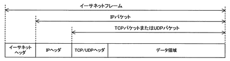
図2を参照して、イーサネットフレームは、イーサネットヘッダと1つのIPパケットとを含む。イーサネットフレームにおいてIPパケットが含まれる領域が、イーサネットフレームのペイロードである。 With reference to FIG. 2, the Ethernet frame contains an Ethernet header and one IP packet. The area in which the IP packet is included in the Ethernet frame is the payload of the Ethernet frame.
IPパケットは、IPヘッダと1つのTCPパケットまたは1つのUDPパケットとを含む。IPパケットにおいてTCPパケットまたはUDPパケットが含まれる領域が、IPパケットのペイロードである。 The IP packet includes an IP header and one TCP packet or one UDP packet. The area of the IP packet that includes the TCP packet or UDP packet is the payload of the IP packet.
TCPパケットまたはUDPパケットは、TCPヘッダまたはUDPヘッダとデータ領域とを含む。TCPパケットまたはUDPパケットにおけるデータ領域が、TCPパケットまたはUDPパケットのペイロードである。 The TCP packet or UDP packet includes a TCP header or UDP header and a data area. The data area in the TCP packet or UDP packet is the payload of the TCP packet or UDP packet.
イーサネットヘッダには、送信先MAC(Media Access Control)アドレスおよび送信元MACアドレスが含まれる。 The Ethernet header contains a destination MAC (Media Access Control) address and a source MAC address.
IPヘッダには、送信先IPアドレスおよび送信元IPアドレスが含まれる。また、IPヘッダには、通信プロトコルの種類を示すプロトコル番号が含まれる。たとえば、TCPの場合、通信プロトコル番号は6である。UDPの場合、通信プロトコル番号は17である。また、IPヘッダには、フラグフィールドおよびフラグオフセットフィールドが含まれる。フラグフィールドおよびフラグオフセットフィールドの詳細は後述する。 The IP header contains a destination IP address and a source IP address. Further, the IP header includes a protocol number indicating the type of communication protocol. For example, in the case of TCP, the communication protocol number is 6. In the case of UDP, the communication protocol number is 17. The IP header also includes a flag field and a flag offset field. Details of the flag field and the flag offset field will be described later.
TCPヘッダまたはUDPヘッダには、送信先ポート番号および送信元ポート番号が含まれる。 The TCP header or UDP header contains a destination port number and a source port number.
[フローデータ]
再び図1を参照して、スイッチ装置101は、車載ネットワーク12におけるフローデータを中継する。
[Flow data]
With reference to FIG. 1 again, the
詳細には、車載機器111は、たとえば、サイズの大きいデータを他の車載機器111へ送信する場合、当該データを複数に分割する。車載機器111によって分割されたデータをそれぞれ含む複数のIPパケットによりフローデータが構成される。車載機器111は、フローデータを他の車載機器111へ送信する。 Specifically, for example, when transmitting large-sized data to another vehicle-mounted device 111, the vehicle-mounted device 111 divides the data into a plurality of pieces. Flow data is composed of a plurality of IP packets including data divided by the in-vehicle device 111. The in-vehicle device 111 transmits the flow data to another in-vehicle device 111.
より詳細には、IPヘッダにおけるフラグフィールドには、フローデータを構成するIPパケットのうちの、途中のIPパケットであることを示すフラグ(以下、途中フラグとも称する。)が含まれる。 More specifically, the flag field in the IP header includes a flag (hereinafter, also referred to as an intermediate flag) indicating that the IP packet is an intermediate IP packet among the IP packets constituting the flow data.
途中フラグがゼロの場合、当該IPパケットは、フローデータのうちの最後のIPパケット(以下、最終IPパケットとも称する。)であるか、または分割されたデータを含まないIPパケットである。 When the intermediate flag is zero, the IP packet is the last IP packet of the flow data (hereinafter, also referred to as the final IP packet), or is an IP packet that does not include the divided data.
途中フラグが1の場合、当該IPパケットは、フローデータのうちの最終IPパケット以外のIPパケット、具体的には1番目のIPパケット(以下、先頭IPパケットとも称する。)および2番目のIPパケット等である。 When the intermediate flag is 1, the IP packet is an IP packet other than the last IP packet in the flow data, specifically, the first IP packet (hereinafter, also referred to as the first IP packet) and the second IP packet. And so on.
フラグオフセットフィールドは、当該IPパケットに格納されるデータの位置を示す値を含む。たとえば、先頭IPパケットでは、フラグオフセットフィールドの値はゼロである。 The flag offset field contains a value indicating the position of the data stored in the IP packet. For example, in the first IP packet, the value of the flag offset field is zero.
したがって、途中フラグが1であり、かつフラグオフセットフィールドの値がゼロの場合、当該IPパケットは先頭IPパケットである。また、途中フラグが1であり、かつフラグオフセットフィールドの値がゼロ以外の場合、当該IPパケットは、フローデータから最終IPパケットを除いたうちの2番目以降のIPパケット(以下、中間IPパケットとも称する。)である。また、途中フラグがゼロであり、かつフラグオフセットフィールドの値がゼロ以外の場合、当該IPパケットは、最終IPパケットである。 Therefore, when the intermediate flag is 1 and the value of the flag offset field is zero, the IP packet is the first IP packet. When the intermediate flag is 1 and the value of the flag offset field is other than zero, the IP packet is the second and subsequent IP packets obtained by excluding the final IP packet from the flow data (hereinafter, also referred to as an intermediate IP packet). It is called.). If the midway flag is zero and the value of the flag offset field is other than zero, the IP packet is the final IP packet.
図3は、本発明の第1の実施の形態に係る車載通信システムにおけるスイッチ装置の構成を示す図である。 FIG. 3 is a diagram showing a configuration of a switch device in an in-vehicle communication system according to the first embodiment of the present invention.
図3を参照して、スイッチ装置101は、第1の半導体集積回路51と、第2の半導体集積回路52と、複数の通信ポート54とを備える。
With reference to FIG. 3, the
スイッチ装置101における通信ポート54は、たとえばイーサネットケーブルを接続可能な端子である。なお、通信ポート54は、集積回路の端子であってもよい。
The
複数の通信ポート54の各々は、たとえば、イーサネットケーブルを介して複数の車載機器111のうちのいずれか1つに接続されている。
Each of the plurality of
図4は、本発明の第1の実施の形態に係るスイッチ装置における第2の半導体集積回路の構成を示す図である。 FIG. 4 is a diagram showing a configuration of a second semiconductor integrated circuit in the switch device according to the first embodiment of the present invention.
図4を参照して、第2の半導体集積回路52は、通信部21と、中継部22と、記憶部23と、切替部24と、複数のポート部25とを含む。
With reference to FIG. 4, the second semiconductor integrated
図5は、本発明の第1の実施の形態に係る第2の半導体集積回路におけるポート部の構成を示す図である。 FIG. 5 is a diagram showing a configuration of a port portion in a second semiconductor integrated circuit according to the first embodiment of the present invention.
図5を参照して、ポート部25は、受信部31と、フィルタ部32と、送信部33とを含む。
With reference to FIG. 5, the
図6は、本発明の第1の実施の形態に係るスイッチ装置における第1の半導体集積回路の構成を示す図である。 FIG. 6 is a diagram showing a configuration of a first semiconductor integrated circuit in the switch device according to the first embodiment of the present invention.
図6を参照して、第1の半導体集積回路51は、通信部41と、経路検索部42と、指示部43と、検査部44とを含む。
With reference to FIG. 6, the first semiconductor integrated
図4および図5を参照して、第2の半導体集積回路52は、たとえば、L2スイッチであり、外部からのイーサネットフレームの受信および外部へのイーサネットフレームの送信を行う。
With reference to FIGS. 4 and 5, the second semiconductor integrated
より詳細には、第2の半導体集積回路52におけるポート部25は、通信ポート54に対応して設けられる。
More specifically, the
ポート部25における送信部33は、切替部24からイーサネットフレームを受けると、受けたイーサネットフレームを対応の通信ポート54経由で宛先の車載機器111へ送信する。
When the
受信部31は、たとえば、バッファを有し、車載機器111から対応の通信ポート54経由でイーサネットフレームを受信すると、受信したイーサネットフレームを当該バッファに保存し、保存したイーサネットフレームをフィルタ部32へ出力する。
The receiving
また、受信部31は、たとえば、受信データの伝送速度が所定の制限値より大きい場合、伝送速度の低下要求を送信部33経由で接続先の車載機器111へ送信することにより、受信データの伝送速度を制限する。
Further, for example, when the transmission speed of the received data is higher than a predetermined limit value, the receiving
フィルタ部32は、受信部31からイーサネットフレームを受けると、所定条件に基づいて、受けたイーサネットフレームを切替部24へ出力するか、または破棄するかを判断する。
When the
より詳細には、フィルタ部32は、たとえば、ユーザによって設定されたACL(Access Control List)に従って、イーサネットフレームを切替部24へ出力するか、または破棄するかを判断する。
More specifically, the
図7は、本発明の第1の実施の形態に係る切替部において用いられるARLテーブルの一例を示す図である。 FIG. 7 is a diagram showing an example of an ARL table used in the switching unit according to the first embodiment of the present invention.
図7を参照して、ARL(Address Resolution Logic)テーブルTablは、送信先MACアドレスと出力先との対応関係を示す。なお、車載ネットワーク12においてVLAN(Virtual Local Area Network)を設定する場合、ARLテーブルTab1は、送信先MACアドレスとVLANのIDと出力先との対応関係を示してもよい。
With reference to FIG. 7, the ARL (Adress Resolution Logical) table Tabl shows the correspondence between the destination MAC address and the output destination. When a VLAN (Virtual Local Area Network) is set in the vehicle-mounted
出力先は、たとえば論理ポート番号である。この論理ポート番号は、たとえば、通信ポート54の物理番号、第1の半導体集積回路51および中継部22のいずれか1つを示す。
The output destination is, for example, a logical port number. The logical port number indicates, for example, any one of the physical number of the
具体的には、ゼロ〜6の論理ポート番号は、出力先が通信ポート54であることを示す。7の論理ポート番号は、出力先が中継部22であることを示す。8の論理ポート番号は、出力先が第1の半導体集積回路51であることを示す。「MAC−DA8」は、たとえばスイッチ装置101のMACアドレス(以下、スイッチアドレスとも称する。)である。
Specifically, the logical port numbers from zero to 6 indicate that the output destination is the
なお、図7では、「MAC−DA8」に対応する論理ポート番号は8であるが、7に書き換えられることがある。当該論理ポート番号の書き換えについては後述する。 In FIG. 7, the logical port number corresponding to "MAC-DA8" is 8, but it may be rewritten to 7. The rewriting of the logical port number will be described later.
切替部24は、たとえば、自己のスイッチ装置101が受信したイーサネットフレームを検査部44(図6参照)へ出力するか、中継部22へ出力するかを切り替える。また、切替部24は、たとえば、最初のイーサネットフレームを検査部44へ出力し、最初のイーサネットフレームが検査処理に合格した場合、2番目以降のフレームを中継部22へ出力する。
The switching
(L2レベルで中継可能なイーサネットフレームの処理)
切替部24は、たとえば、ARLテーブルTab1を保持しており、ポート部25からイーサネットフレームを受けると、受けたイーサネットフレームにおけるMACヘッダに含まれる送信先MACアドレスを確認する。
(Processing of Ethernet frames that can be relayed at L2 level)
The switching
切替部24は、ARLテーブルTab1を参照し、確認した送信先MACアドレスに対応する出力先をARLテーブルTab1から取得する。
The switching
具体的には、切替部24は、たとえば、L2レベルで中継可能なイーサネットフレームについては、出力先としてゼロ〜6のうちのいずれかの論理ポート番号をARLテーブルTab1から取得する。
Specifically, for example, for an Ethernet frame that can be relayed at the L2 level, the switching
そして、切替部24は、当該イーサネットフレームにおけるMACヘッダに含まれる送信元MACアドレスをスイッチアドレスに書き換えた後、取得した論理ポート番号に対応するポート部25へ当該イーサネットフレームを出力する。
Then, the switching
(最初のイーサネットフレームの処理)
切替部24は、たとえば、ポート部25からイーサネットフレームを受けて、受けたイーサネットフレームにおけるMACヘッダに含まれる送信先MACアドレスがスイッチアドレスすなわち「MAC−DA8」である場合、当該イーサネットフレームがL3レベルでの中継処理を要するイーサネットフレームであることを認識する。
(Processing of first Ethernet frame)
For example, when the switching
そして、切替部24は、イーサネットフレームに含まれるIPパケットにおける途中フラグの値およびフラグオフセットの値を確認する。
Then, the switching
切替部24は、確認した各値に基づいて、イーサネットフレームが先頭IPパケットを含むか否かを判定する。
The switching
切替部24は、イーサネットフレームが先頭IPパケットを含むと判定した場合、当該イーサネットフレームが最初のイーサネットフレームであると認識する。
When the switching
そして、切替部24、ARLテーブルTab1における「MAC−DA8」に対応する出力先が7である場合、8に書き換える。
Then, when the output destination corresponding to "MAC-DA8" in the
切替部24は、出力先として8の論理ポート番号をARLテーブルTab1から取得し、取得した論理ポート番号に対応する通信部21へ当該イーサネットフレームを出力する。
The switching
通信部21は、第1の半導体集積回路51とデータの送受信を行うことが可能である。より詳細には、通信部21は、切替部24からイーサネットフレームを受けると、受けたイーサネットフレームを第1の半導体集積回路51へ送信する。
The
再び図6を参照して、第1の半導体集積回路51における通信部41は、第2の半導体集積回路52とデータの送受信を行うことが可能である。より詳細には、通信部41は、第2の半導体集積回路52からイーサネットフレームを受信すると、受信したイーサネットフレームを検査部44へ出力する。
With reference to FIG. 6 again, the
検査部44は、たとえば、自己のスイッチ装置101が受信するイーサネットフレームの検査処理を行う。また、検査部44は、たとえば、フローデータを構成する最初のイーサネットフレームが検査処理に合格した場合、2番目以降のイーサネットフレームの検査処理を行わない。
The
より詳細には、検査部44は、ファイアウォールとして機能し、通信部41からイーサネットフレームを受けると、受けたイーサネットフレームに含まれるIPパケットの検査処理を行う。
More specifically, the
具体的には、検査部44は、IPパケットについてSPI(Stateful Packet Inspection)を行い、異常を発見した場合、当該IPパケットを含むイーサネットフレームを破棄する。
Specifically, the
一方、検査部44は、異常を発見しない場合、当該IPパケットを含むイーサネットフレームを経路検索部42へ出力する。
On the other hand, if the
経路検索部42は、たとえば、IPパケットの送信経路を検索するとともに、当該IPパケットのヘッダに格納されたTTL(Time To Live)値を1つ減算する。
The
より詳細には、経路検索部42は、たとえば、宛先ネットワークと送出インタフェースとの対応関係を示すルーティングテーブルを保持している。また、経路検索部42は、たとえば、IPアドレスとMACアドレスとの対応関係を示すARP(Address Resolution Protocol)テーブルを送出インタフェースごとに保持している。
More specifically, the
経路検索部42は、検査部44からイーサネットフレームを受けると、受けたイーサネットフレームに含まれるIPパケットから送信先IPアドレスを取得し、たとえば、取得した送信先IPアドレスに対してサブネットマスク計算を行うことにより宛先ネットワークを特定する。
When the
経路検索部42は、ルーティングテーブルを参照し、特定した宛先ネットワークに対応する送出インタフェースを特定する。
The
そして、経路検索部42は、特定した送出インタフェースに対応するARPテーブルを参照し、送信先IPアドレスに対応するMACアドレス(以下、検索アドレスとも称する。)を当該ARPテーブルから取得する。
Then, the
経路検索部42は、イーサネットフレームの送信先MACアドレスおよび送信元MACアドレスを、それぞれ検索アドレスおよびスイッチアドレスに書き換え、当該イーサネットフレームを指示部43へ出力する。
The
指示部43は、切替部24においてL3レベルでの中継処理を要するイーサネットフレームの出力先を、自己の第1の半導体集積回路51から中継部22に切り替えるための指示情報を作成し、作成した指示情報を通信部41経由で第2の半導体集積回路52へ送信する。
The
より詳細には、指示部43は、経路検索部42からイーサネットフレームを受けると、ARLテーブルTab1における「MAC−DA8」に対応する出力先を8から7に書き換えることを含む指示情報を作成する。
More specifically, when the
指示部43は、作成した指示情報をイーサネットフレームに付して、通信部41経由で第2の半導体集積回路52へ送信する。
The
再び図4を参照して、第2の半導体集積回路52における切替部24は、通信部21経由で第1の半導体集積回路51から指示情報の付されたイーサネットフレームを受信すると、受信したイーサネットフレームにおけるMACヘッダに含まれる送信先MACアドレスを確認する。
With reference to FIG. 4 again, when the switching
切替部24は、ARLテーブルTab1を参照し、確認した送信先MACアドレスすなわち検索アドレスに対応する出力先をARLテーブルTab1から取得する。
The switching
この場合、切替部24は、たとえば、出力先としてゼロ〜6のうちのいずれかの論理ポート番号をARLテーブルTab1から取得し、取得した論理ポート番号に対応するポート部25へ当該イーサネットフレームを出力する。
In this case, for example, the switching
また、切替部24は、第1の半導体集積回路51から受信した指示情報に従って、ARLテーブルTab1における「MAC−DA8」に対応する出力先を8から7に書き換える。
Further, the switching
(2番目以降のイーサネットフレームの処理)
切替部24は、たとえば、ポート部25からイーサネットフレームを受けて、受けたイーサネットフレームがL3レベルでの中継処理を要するイーサネットフレームであることを認識すると、当該イーサネットフレームに含まれるIPパケットにおける途中フラグの値およびフラグオフセットの値を確認する。
(Processing of the second and subsequent Ethernet frames)
When the switching
切替部24は、確認した各値に基づいて、イーサネットフレームが中間IPパケットまたは最終IPパケットを含むと判定すると、出力先として7の論理ポート番号をARLテーブルTab1から取得し、取得した論理ポート番号に対応する中継部22へ当該イーサネットフレームを出力する。
When the switching
図8は、本発明の第1の実施の形態に係るスイッチ装置における記憶部が保持する変換用テーブルの一例を示す図である。 FIG. 8 is a diagram showing an example of a conversion table held by a storage unit in the switch device according to the first embodiment of the present invention.
図8を参照して、記憶部23は、送信先IPアドレスと送信元IPアドレスと通信プロトコルと送信先ポート情報と送信元ポート情報と送信先MACアドレスと送信元MACアドレスとの対応関係を示す対応情報を保持する。また、記憶部23は、たとえば対応情報を固定的に記憶する。
With reference to FIG. 8, the
具体的には、記憶部23は、対応情報の一例である変換用テーブルTab2を記憶する。送信先ポート番号および送信元ポート番号は、それぞれ送信先ポート情報および送信元ポート情報の一例である。
Specifically, the
たとえば、車載ネットワーク12では接続トポロジおよびIPアドレスが固定的に運用されるので、L3中継のすべての組み合わせを予め決定することが可能である。変換用テーブルTab2は、たとえば、車載ネットワーク12におけるL3中継の可能な、送信先IPアドレス、送信元IPアドレス、通信プロトコル、送信先ポート番号および送信元ポート番号のすべての組み合わせを含む。
For example, in the in-
再び図4を参照して、中継部22は、自己のスイッチ装置101が受信したイーサネットフレームであってフローデータを構成するイーサネットフレームに含まれる送信先IPアドレス、送信元IPアドレス、通信プロトコル、送信先ポート情報および送信元ポート情報に基づいて、対応情報から送信先MACアドレスを取得する。
With reference to FIG. 4 again, the
そして、中継部22は、取得した送信先MACアドレスをイーサネットフレームに含めて送信する送信処理を行う。詳細には、中継部22は、たとえば、2番目以降のイーサネットフレームに対して送信処理を行う。
Then, the
より詳細には、中継部22は、切替部24から2番目以降のイーサネットフレームを受けると、受けたイーサネットフレームに含まれるIPパケットの内容を確認する。具体的には、中継部22は、送信先IPアドレス、送信元IPアドレス、通信プロトコル、送信先ポート番号および送信元ポート番号を確認する。
More specifically, when the
そして、中継部22は、変換用テーブルTab2を参照し、確認した送信先IPアドレス、送信元IPアドレス、通信プロトコル、送信先ポート番号および送信元ポート番号に対応する送信先MACアドレスおよび送信元MACアドレスを変換用テーブルTab2から取得する。
Then, the
ここでは、送信先MACアドレスおよび送信元MACアドレスは、それぞれ検索アドレスおよびスイッチアドレスである。 Here, the destination MAC address and the source MAC address are a search address and a switch address, respectively.
中継部22は、イーサネットフレームの送信先MACアドレスおよび送信元MACアドレスを、取得した検索アドレスおよびスイッチアドレスにそれぞれ書き換え、イーサネットフレームを切替部24へ出力する。
The
切替部24は、イーサネットフレームを中継部22から受けると、受けたイーサネットフレームにおけるMACヘッダに含まれる送信先MACアドレスを確認する。
When the switching
切替部24は、ARLテーブルTab1を参照し、確認した送信先MACアドレスすなわち検索アドレスに対応する出力先をARLテーブルTab1から取得する。
The switching
この場合、切替部24は、上述の最初のイーサネットフレームの場合と同じ論理ポート番号を出力先としてARLテーブルTab1から取得し、取得した論理ポート番号に対応するポート部25経由で宛先の車載機器111へイーサネットフレームを送信する。
In this case, the switching
[スイッチ装置101の変形例]
図9は、本発明の第1の実施の形態に係るスイッチ装置の変形例における記憶部が保持する変換用テーブルの一例を示す図である。
[Modification example of switch device 101]
FIG. 9 is a diagram showing an example of a conversion table held by a storage unit in a modified example of the switch device according to the first embodiment of the present invention.
図9を参照して、記憶部23は、送信先IPアドレスと送信元IPアドレスと通信プロトコルと送信先ポート情報と送信元ポート情報とを一意に決定する値と送信先MACアドレスと送信元MACアドレスとの対応関係を示す対応情報を保持する。また、記憶部23は、たとえば対応情報を固定的に記憶する。
With reference to FIG. 9, the
具体的には、記憶部23は、対応情報の一例である変換用テーブルTab3を記憶する。ハッシュ値は、送信先IPアドレスと送信元IPアドレスと通信プロトコルと送信先ポート情報と送信元ポート情報とを一意に決定する値の一例である。
Specifically, the
より詳細には、ハッシュ値は、送信先IPアドレス、送信元IPアドレス、通信プロトコル、送信先ポート番号および送信元ポート番号を検索キーとして、所定の計算手順P1を用いて生成される値である。 More specifically, the hash value is a value generated by using a predetermined calculation procedure P1 using the destination IP address, the source IP address, the communication protocol, the destination port number, and the source port number as search keys. ..
変換用テーブルTab3は、たとえば、車載ネットワーク12におけるL3中継の可能な、送信先IPアドレス、送信元IPアドレス、通信プロトコル、送信先ポート番号および送信元ポート番号のすべての組み合わせについてのハッシュ値を含む。
The conversion table Tab3 contains, for example, hash values for all combinations of destination IP address, source IP address, communication protocol, destination port number, and source port number that can be relayed by L3 in the in-
また、変換用テーブルTab3におけるハッシュ値は、値が重複しないように予めチェックされる。たとえば、重複するハッシュ値が存在する場合、他の計算手順を用いて新たなハッシュ値を生成し、変換用テーブルTab3におけるハッシュ値が重複しないようにする。
Further, the hash values in the
再び図4を参照して、中継部22は、自己のスイッチ装置101が受信したイーサネットフレームであってフローデータを構成するイーサネットフレーム、に含まれる値であってイーサネットフレームの送信先IPアドレス、送信元IPアドレス、通信プロトコル、送信先ポート情報および送信元ポート情報を一意に決定する値に対応する送信先MACアドレスを対応情報から取得する。
With reference to FIG. 4 again, the
そして、中継部22は、取得した送信先MACアドレスをイーサネットフレームに含めて送信する送信処理を行う。詳細には、中継部22は、たとえば、少なくとも2番目以降のイーサネットフレームに対して送信処理を行う。
Then, the
(2番目以降のイーサネットフレームの処理)
より詳細には、中継部22は、切替部24から2番目以降のイーサネットフレームを受けると、受けたイーサネットフレームから送信先IPアドレス、送信元IPアドレス、通信プロトコル、送信先ポート番号および送信元ポート番号を取得する。
(Processing of the second and subsequent Ethernet frames)
More specifically, when the
中継部22は、取得した送信先IPアドレス、送信元IPアドレス、通信プロトコル、送信先ポート番号および送信元ポート番号を検索キーとして、計算手順P1を用いてハッシュ値を生成する。
The
そして、中継部22は、変換用テーブルTab3を参照し、生成したハッシュ値に対応する送信先MACアドレスおよび送信元MACアドレスを変換用テーブルTab3から取得する。
Then, the
ここでは、送信先MACアドレスおよび送信元MACアドレスは、それぞれ検索アドレスおよびスイッチアドレスである。 Here, the destination MAC address and the source MAC address are a search address and a switch address, respectively.
中継部22は、イーサネットフレームの送信先MACアドレスおよび送信元MACアドレスを、取得した検索アドレスおよびスイッチアドレスにそれぞれ書き換え、イーサネットフレームを切替部24へ出力する。
The
[動作の流れ]
車載通信システム301における各装置は、コンピュータを備え、当該コンピュータにおけるCPU等の演算処理部は、以下のシーケンス図またはフローチャートの各ステップの一部または全部を含むプログラムを図示しないメモリからそれぞれ読み出して実行する。これら複数の装置のプログラムは、それぞれ、外部からインストールすることができる。これら複数の装置のプログラムは、それぞれ、記録媒体に格納された状態で流通する。
[Operation flow]
Each device in the in-
図10は、本発明の第1の実施の形態に係る車載通信システムにおけるスイッチ装置がイーサネットフレームの中継処理を行う際の動作手順を定めたフローチャートである。 FIG. 10 is a flowchart defining an operation procedure when the switch device in the in-vehicle communication system according to the first embodiment of the present invention performs relay processing of an Ethernet frame.
図10を参照して、まず、スイッチ装置101は、車載機器111からイーサネットフレームを受信するまで待機する(ステップS102でNO)。
With reference to FIG. 10, first, the
そして、スイッチ装置101は、車載機器111からイーサネットフレームを受信すると(ステップS102でYES)、受信したイーサネットフレームがL2レベルで中継することが可能な場合(ステップS104でYES)、以下の処理を行う。
Then, when the
すなわち、スイッチ装置101は、イーサネットフレームの送信元MCAアドレスをスイッチアドレスに書き換えた後、当該イーサネットフレームを宛先の車載機器111へ送信する(ステップS116)。
That is, the
一方、スイッチ装置101は、受信したイーサネットフレームがL3レベルでの中継処理を要するイーサネットフレームである場合(ステップS104でNO)、イーサネットフレームが最初のイーサネットフレームであるか否かを判定する(ステップS106)。
On the other hand, when the received Ethernet frame is an Ethernet frame that requires relay processing at the L3 level (NO in step S104), the
スイッチ装置101は、イーサネットフレームが2番目以降のイーサネットフレームであると判定すると(ステップS106でNO)、後述する高速中継処理を行う(ステップS118)。
When the
一方、スイッチ装置101は、イーサネットフレームが最初のイーサネットフレームであると判定すると(ステップS106でYES)、イーサネットフレームの検査処理を行う(ステップS108)。
On the other hand, when the
次に、スイッチ装置101は、イーサネットフレームが検査処理に合格しなかった場合(ステップS110でNO)、当該イーサネットフレームを破棄する(ステップS120)。
Next, when the Ethernet frame does not pass the inspection process (NO in step S110), the
一方、スイッチ装置101は、イーサネットフレームが検査処理に合格した場合(ステップS110でYES)、イーサネットフレームに含まれるIPパケットの経路を検索するとともに、当該IPパケットのヘッダに格納されたTTL値を1つ減算する(ステップS112)。
On the other hand, when the Ethernet frame passes the inspection process (YES in step S110), the
次に、スイッチ装置101は、イーサネットフレームの送信先MACアドレスおよび送信元MACアドレスを、検索結果に基づく検索アドレス、およびスイッチアドレスにそれぞれ書き換えた後、当該イーサネットフレームを宛先の車載機器111へ送信する(ステップS114)。
Next, the
次に、スイッチ装置101は、イーサネットフレームを宛先の車載機器111へ送信するか(ステップS114およびS116)、高速中継処理を行うか(ステップS118)、またはイーサネットフレームを破棄すると(ステップS120)、車載機器111から新たなイーサネットフレームを受信するまで待機する(ステップS102でNO)。
Next, the
図11は、本発明の第1の実施の形態に係る車載通信システムにおけるスイッチ装置が高速中継処理を行う際の動作手順を定めたフローチャートである。図11は、図10のステップS118における動作の詳細を示している。 FIG. 11 is a flowchart defining an operation procedure when the switch device in the in-vehicle communication system according to the first embodiment of the present invention performs high-speed relay processing. FIG. 11 shows the details of the operation in step S118 of FIG.
図11を参照して、まず、スイッチ装置101は、2番目以降のイーサネットフレームに含まれる送信先IPアドレス、送信元IPアドレス、通信プロトコル、送信先ポート番号および送信元ポート番号を確認する(ステップS202)。
With reference to FIG. 11, first, the
次に、スイッチ装置101は、変換用テーブルTab2を参照し、確認した送信先IPアドレス、送信元IPアドレス、通信プロトコル、送信先ポート番号および送信元ポート番号に対応する送信先MACアドレスおよび送信元MACアドレスを変換用テーブルTab2から取得する(ステップS204)。
Next, the
具体的には、スイッチ装置101は、たとえば、送信先MACアドレスおよび送信元MACアドレスとして、それぞれ検索アドレスおよびスイッチアドレスを取得する。
Specifically, the
次に、スイッチ装置101は、イーサネットフレームの送信先MACアドレスおよび送信元MACアドレスを、取得した検索アドレスおよびスイッチアドレスにそれぞれ書き換える(ステップS206)。
Next, the
次に、スイッチ装置101は、送信先MACアドレスおよび送信元MACアドレスを書き換えたイーサネットフレームを宛先の車載機器111へ送信する(ステップS208)。
Next, the
なお、スイッチ装置101は、変換用テーブルTab2を用いる高速中継処理を行う構成に限らず、変換用テーブルTab3を用いる高速中継処理を行う構成であってもよい。
The
図12は、本発明の第1の実施の形態に係る車載通信システムにおけるスイッチ装置が高速中継処理を行う際の動作手順を定めたフローチャートである。図12は、図10のステップS118における動作の詳細を示している。 FIG. 12 is a flowchart defining an operation procedure when the switch device in the in-vehicle communication system according to the first embodiment of the present invention performs high-speed relay processing. FIG. 12 shows the details of the operation in step S118 of FIG.
図12を参照して、まず、スイッチ装置101は、2番目以降のイーサネットフレームに含まれる送信先IPアドレス、送信元IPアドレス、通信プロトコル、送信先ポート番号および送信元ポート番号を検索キーとして、計算手順P1を用いてハッシュ値を生成する(ステップS302)。
With reference to FIG. 12, first, the
次に、スイッチ装置101は、変換用テーブルTab3を参照し、生成したハッシュ値に対応する送信先MACアドレスおよび送信元MACアドレスを変換用テーブルTab3から取得する(ステップS304)。
Next, the
具体的には、スイッチ装置101は、たとえば、送信先MACアドレスおよび送信元MACアドレスとして、それぞれ検索アドレスおよびスイッチアドレスを取得する。
Specifically, the
次に、スイッチ装置101は、イーサネットフレームの送信先MACアドレスおよび送信元MACアドレスを、取得した検索アドレスおよびスイッチアドレスにそれぞれ書き換える(ステップS306)。
Next, the
次に、スイッチ装置101は、送信先MACアドレスおよび送信元MACアドレスを書き換えたイーサネットフレームを宛先の車載機器111へ送信する(ステップS308)。
Next, the
[比較例]
図13は、本発明の第1の実施の形態に係る車載通信システムにおけるスイッチ装置の比較例の構成を示す図である。
[Comparison example]
FIG. 13 is a diagram showing a configuration of a comparative example of a switch device in an in-vehicle communication system according to the first embodiment of the present invention.
図13を参照して、比較例であるスイッチ装置901は、第1の半導体集積回路91と、第2の半導体集積回路62と、複数の通信ポート54とを備える。
With reference to FIG. 13, the
スイッチ装置901における通信ポート54の動作は、図3に示すスイッチ装置101における通信ポート54とそれぞれ同様である。
The operation of the
図14は、本発明の第1の実施の形態に係るスイッチ装置の比較例における第2の半導体集積回路の構成を示す図である。 FIG. 14 is a diagram showing a configuration of a second semiconductor integrated circuit in a comparative example of the switch device according to the first embodiment of the present invention.
図14を参照して、第2の半導体集積回路62は、通信部21と、複数のポート部25と、転送先決定部26とを含む。
With reference to FIG. 14, the second semiconductor integrated
第2の半導体集積回路62における通信部21およびポート部25の動作は、図4に示す第2の半導体集積回路52における通信部21およびポート部25とそれぞれ同様である。
The operations of the
図14を参照して、第2の半導体集積回路62は、たとえば、L2スイッチであり、外部からのイーサネットフレームの受信および外部へのイーサネットフレームの送信を行う。
With reference to FIG. 14, the second semiconductor integrated
より詳細には、第2の半導体集積回路62における転送先決定部26は、ARLテーブルTab1(図7参照)を保持する。
More specifically, the transfer
ここでは、出力先は、たとえば、通信ポート54の物理番号および第1の半導体集積回路91のいずれか一方を示す。
Here, the output destination indicates, for example, either the physical number of the
具体的には、ゼロ〜6の論理ポート番号は、出力先が通信ポート54であることを示す。8の論理ポート番号は、出力先が第1の半導体集積回路91であることを示す。
Specifically, the logical port numbers from zero to 6 indicate that the output destination is the
「MAC−DA8」は、たとえばスイッチ装置901のMACアドレスすなわちスイッチアドレスである。この例では、「MAC−DA8」に対応する論理ポート番号はたとえば8に固定されている。
“MAC-DA8” is, for example, the MAC address of the
(L2レベルで中継可能なイーサネットフレームの処理)
転送先決定部26は、たとえば、ポート部25からイーサネットフレームを受けると、受けたイーサネットフレームにおけるMACヘッダに含まれる送信先MACアドレスを確認する。
(Processing of Ethernet frames that can be relayed at L2 level)
When the transfer
転送先決定部26は、ARLテーブルTab1を参照し、確認した送信先MACアドレスに対応する出力先をARLテーブルTab1から取得する。
The transfer
具体的には、転送先決定部26は、たとえば、L2レベルで中継可能なイーサネットフレームについては、出力先としてゼロ〜6のうちのいずれかの論理ポート番号をARLテーブルTab1から取得する。
Specifically, the transfer
そして、転送先決定部26は、当該イーサネットフレームにおけるMACヘッダに含まれる送信元MACアドレスをスイッチアドレスに書き換えた後、取得した論理ポート番号に対応するポート部25へ当該イーサネットフレームを出力する。
Then, the transfer
また、転送先決定部26は、たとえば、L3レベルでの中継処理を要するイーサネットフレームについては、出力先として8の論理ポート番号をARLテーブルTab1から取得する。
Further, the transfer
そして、切替部24は、当該イーサネットフレームを通信部21経由で第1の半導体集積回路91へ送信する。
Then, the switching
図15は、本発明の第1の実施の形態に係るスイッチ装置の比較例における第1の半導体集積回路の構成を示す図である。 FIG. 15 is a diagram showing a configuration of a first semiconductor integrated circuit in a comparative example of a switch device according to a first embodiment of the present invention.
図15を参照して、第1の半導体集積回路91は、通信部41と、経路検索部42と、検査部44と、記憶部73と、リスト管理部92とを含む。
With reference to FIG. 15, the first semiconductor integrated
第1の半導体集積回路91における通信部41、経路検索部42および検査部44の動作は、図6に示す第1の半導体集積回路51における通信部41、経路検索部42および検査部44とそれぞれ同様である。
The operations of the
図16は、本発明の第1の実施の形態に係るスイッチ装置の比較例における記憶部が保持するフローリストの一例を示す図である。 FIG. 16 is a diagram showing an example of a florist held by a storage unit in a comparative example of the switch device according to the first embodiment of the present invention.
図16を参照して、第1の半導体集積回路91における記憶部73は、たとえば、送信先IPアドレスと送信元IPアドレスと通信プロトコルと送信先ポート番号と送信元ポート番号とタイムスタンプとの対応関係を示すフローリストLst1を記憶する。
With reference to FIG. 16, the
フローリストLst1は、図8に示す変換用テーブルTab2等と異なり、車載ネットワーク12におけるL3中継の可能な、送信先IPアドレス、送信元IPアドレス、通信プロトコル、送信先ポート番号および送信元ポート番号のすべての組み合わせを常時含まない。フローリストLst1の内容は、たとえばリスト管理部92によって動的に変更される。
Unlike the conversion table Tab2 and the like shown in FIG. 8, the flow list Lst1 has a destination IP address, a source IP address, a communication protocol, a destination port number, and a source port number that can be relayed by L3 in the in-
(最初のイーサネットフレームの処理)
再び図15を参照して、リスト管理部92は、L3レベルでの中継処理を要する最初のイーサネットフレームを通信部41経由で第2の半導体集積回路62から受信すると、受信したイーサネットフレームに含まれるIPパケットの内容を確認する。具体的には、リスト管理部92は、送信先IPアドレス、送信元IPアドレス、通信プロトコル、送信先ポート番号および送信元ポート番号を確認する。
(Processing of first Ethernet frame)
With reference to FIG. 15 again, when the
そして、リスト管理部92は、フローリストLst1を参照し、確認した送信先IPアドレス、送信元IPアドレス、通信プロトコル、送信先ポート番号および送信元ポート番号がフローリストLst1に登録されているか否かを確認する。
Then, the
リスト管理部92は、登録されていないことを確認すると、第2の半導体集積回路62から受信したイーサネットフレームが最初のイーサネットフレームであると判断し、当該イーサネットフレームを検査部44へ出力する。
When the
検査部44は、切替部74からイーサネットフレームを受けると、受けたイーサネットフレームに含まれるIPパケットの検査処理を行い、異常を発見した場合、当該IPパケットを含むイーサネットフレームを破棄する。
When the
一方、検査部44は、異常を発見しない場合、当該IPパケットを含むイーサネットフレームを経路検索部42へ出力する。
On the other hand, if the
リスト管理部92は、記憶部73が保持するフローリストLst1を管理する。より詳細には、リスト管理部92は、イーサネットフレームを検査部44へ出力した後、検査部44における当該イーサネットフレームの検査処理を監視する。
The
リスト管理部92は、検査部44が当該イーサネットフレームについて異常を発見しない場合、当該イーサネットフレームに含まれる送信先IPアドレス、送信元IPアドレス、通信プロトコル、送信先ポート番号および送信元ポート番号、ならびに現在時刻を示すタイムスタンプ(以下、これらをフロー情報とも称する。)をフローリストLst1に登録する。
If the
一方、リスト管理部92は、検査部44が当該イーサネットフレームについて異常を異常を発見した場合、当該イーサネットフレームについてのフロー情報をフローリストLst1に登録しない。
On the other hand, when the
経路検索部42は、検査部44からイーサネットフレームを受けると、受けたイーサネットフレームに含まれるIPパケットのヘッダに格納されたTTL値を1つ減算するとともに、以下の処理を行う。
When the
すなわち、経路検索部42は、ルーティングテーブルおよびARPテーブルに基づいて、送信先IPアドレスに対応するMACアドレスすなわち検索アドレスを取得する。
That is, the
そして、経路検索部42は、イーサネットフレームの送信先MACアドレスおよび送信元MACアドレスを、検索アドレスおよびスイッチアドレスにそれぞれ書き換え、イーサネットフレームを通信部41経由で第2の半導体集積回路62へ送信する。
Then, the
再び図14を参照して、第2の半導体集積回路62における転送先決定部26は、通信部21経由で第1の半導体集積回路91からイーサネットフレームを受信すると、受信したイーサネットフレームにおけるMACヘッダに含まれる送信先MACアドレスを確認する。
With reference to FIG. 14 again, when the transfer
転送先決定部26は、ARLテーブルTab1を参照し、確認した送信先MACアドレスすなわち検索アドレスに対応する出力先をARLテーブルTab1から取得する。
The transfer
この場合、転送先決定部26は、たとえば、出力先としてゼロ〜6のうちのいずれかの論理ポート番号をARLテーブルTab1から取得し、取得した論理ポート番号に対応するポート部25経由で宛先の車載機器111へイーサネットフレームを送信する。
In this case, the transfer
(2番目以降のイーサネットフレームの処理)
再び図15を参照して、リスト管理部92は、L3レベルでの中継処理を要する2番目以降のイーサネットフレームを通信部41経由で第2の半導体集積回路62から受信すると、受信したイーサネットフレームに含まれる送信先IPアドレス、送信元IPアドレス、通信プロトコル、送信先ポート番号および送信元ポート番号を確認する。
(Processing of the second and subsequent Ethernet frames)
With reference to FIG. 15 again, when the
そして、リスト管理部92は、フローリストLst1を参照し、確認した送信先IPアドレス、送信元IPアドレス、通信プロトコル、送信先ポート番号および送信元ポート番号がフローリストLst1に登録されているか否かを確認する。
Then, the
リスト管理部92は、登録されていることを確認すると、第2の半導体集積回路62から受信したイーサネットフレームが2番目以降のイーサネットフレームであると判断し、当該イーサネットフレームを経路検索部42へ出力する。
Upon confirming that the
また、リスト管理部92は、たとえば、タイムスタンプの示す時刻から所定時間経過した場合、およびフローデータのうちの最終IPパケットを含むイーサネットフレームを処理した場合において、対応のフロー情報をフローリストLst1から抹消する。
Further, the
なお、本発明の第1の実施の形態に係るスイッチ装置では、対応情報は、送信先IPアドレスと送信元IPアドレスと通信プロトコルと送信先ポート情報と送信元ポート情報と送信先MACアドレスと送信元MACアドレスとの対応関係を示す構成であるとしたが、これに限定するものではない。対応情報は、通信プロトコルおよび送信元MACアドレスを含まず、送信先IPアドレスと送信元IPアドレスと送信先ポート情報と送信元ポート情報と送信先MACアドレスとの対応関係を示す構成であってもよい。たとえば、車載ネットワーク12における通信プロトコルがTCPおよびUDPのいずれか一方に固定されている場合、上記構成により、車載ネットワークにおけるIPパケットの中継処理を効率よく行うという本発明の目的を達成することが可能である。また、対応情報は、送信元MACアドレスを含まず、送信先IPアドレスと送信元IPアドレスと通信プロトコルと送信先ポート情報と送信元ポート情報と送信先MACアドレスとの対応関係を示す構成であってもよい。
In the switch device according to the first embodiment of the present invention, the corresponding information includes the destination IP address, the source IP address, the communication protocol, the destination port information, the source port information, the destination MAC address, and the transmission. The configuration shows the correspondence with the original MAC address, but the configuration is not limited to this. The correspondence information does not include the communication protocol and the source MAC address, and even if the configuration shows the correspondence between the destination IP address, the source IP address, the destination port information, the source port information, and the destination MAC address. Good. For example, when the communication protocol in the vehicle-mounted
また、本発明の第1の実施の形態に係るスイッチ装置では、中継部22は、イーサネットフレームに含まれる送信先IPアドレス、送信元IPアドレス、通信プロトコル、送信先ポート情報および送信元ポート情報に基づいて、対応情報から送信先MACアドレスを取得する構成であるとしたが、これに限定するものではない。中継部22は、通信プロトコルを除く、イーサネットフレームに含まれる送信先IPアドレス、送信元IPアドレス、送信先ポート情報および送信元ポート情報に基づいて、対応情報から送信先MACアドレスを取得する構成であってもよい。
Further, in the switch device according to the first embodiment of the present invention, the
また、本発明の第1の実施の形態に係るスイッチ装置の変形例では、対応情報は、送信先IPアドレスと送信元IPアドレスと通信プロトコルと送信先ポート情報と送信元ポート情報とを一意に決定する値と送信先MACアドレスと送信元MACアドレスとの対応関係を示す構成であるとしたが、これに限定するものではない。対応情報は、通信プロトコルを除く、送信先IPアドレスと送信元IPアドレスと送信先ポート情報と送信元ポート情報とを一意に決定する値と送信先MACアドレスとの対応関係を示す構成であってもよい。たとえば、車載ネットワーク12における通信プロトコルがTCPおよびUDPのいずれか一方に固定されている場合、上記構成により、車載ネットワークにおけるIPパケットの中継処理を効率よく行うという本発明の目的を達成することが可能である。また、対応情報は、送信先IPアドレスと送信元IPアドレスと通信プロトコルと送信先ポート情報と送信元ポート情報とを一意に決定する値と送信先MACアドレスとの対応関係を示す構成であってもよい。
Further, in the modification of the switch device according to the first embodiment of the present invention, the corresponding information uniquely sets the destination IP address, the source IP address, the communication protocol, the destination port information, and the source port information. The configuration shows the correspondence between the value to be determined, the destination MAC address, and the source MAC address, but the configuration is not limited to this. The correspondence information is configured to show the correspondence relationship between the destination MAC address and the value that uniquely determines the destination IP address, the source IP address, the destination port information, and the source port information, excluding the communication protocol. May be good. For example, when the communication protocol in the vehicle-mounted
また、本発明の第1の実施の形態に係るスイッチ装置では、記憶部23が第2の半導体集積回路の内部に設けられる構成であるとしたが、これに限定するものではない。記憶部23が第2の半導体集積回路52の外部に設けられる構成であってもよい。
Further, in the switch device according to the first embodiment of the present invention, the
また、本発明の第1の実施の形態に係るスイッチ装置では、対応情報が予め記憶部23に保持される構成であるとしたが、これに限定するものではない。たとえば、スイッチ装置101は、フローデータの処理を行うごとに送信先IPアドレスと送信元IPアドレスと通信プロトコルと送信先ポート情報と送信元ポート情報と送信先MACアドレスと送信元MACアドレスとの対応関係を取得し、取得した対応関係によって記憶部23における対応情報を更新する取得部を備える構成であってもよい。
Further, the switch device according to the first embodiment of the present invention is configured to hold the corresponding information in the
また、本発明の第1の実施の形態に係るスイッチ装置の変形例では、対応情報が予め記憶部23に保持される構成であるとしたが、これに限定するものではない。たとえば、スイッチ装置101の変形例は、フローデータの処理を行うごとに送信先IPアドレスと送信元IPアドレスと通信プロトコルと送信先ポート情報と送信元ポート情報とを一意に決定する値と送信先MACアドレスと送信元MACアドレスとの対応関係を取得し、取得した対応関係によって記憶部23における対応情報を更新する取得部を備える構成であってもよい。
Further, in the modified example of the switch device according to the first embodiment of the present invention, it is assumed that the corresponding information is stored in the
また、本発明の第1の実施の形態に係るスイッチ装置は、検査部44を備える構成であるとしたが、これに限定するものではない。スイッチ装置101は、たとえば、通信のセキュリティが確保されており、イーサネットフレームに含まれるデータの検査を行う必要がない場合において、切替部24および検査部44を備えない構成であってもよい。この場合、スイッチ装置101は、たとえば、L3レベルでの中継を要するすべてのイーサネットフレームを中継部22へ出力する。
Further, the switch device according to the first embodiment of the present invention is said to have a configuration including an
また、本発明の第1の実施の形態に係るスイッチ装置は、中継部22は、2番目以降のイーサネットフレームに対して送信処理を行う構成であるとしたが、これに限定するものではない。中継部22は、3番目以降のイーサネットフレームに対して送信処理を行う構成であってもよい。
Further, the switch device according to the first embodiment of the present invention has a configuration in which the
また、本発明の第1の実施の形態に係るスイッチ装置は、第1の半導体集積回路51と第2の半導体集積回路52とを備える構成であるとしたが、これに限定するものではない。スイッチ装置101は、たとえば、第1の半導体集積回路51および第2の半導体集積回路52の各機能をまとめた1つの半導体集積回路を備える構成であってもよいし、第1の半導体集積回路51および第2の半導体集積回路52の各機能を3つ以上の半導体集積回路に分割して備える構成であってもよい。
Further, the switch device according to the first embodiment of the present invention is configured to include a first semiconductor integrated
ところで、特許文献1に記載の車載ネットワークでは、車載制御装置からの情報を中継する通信ゲートウェイが設けられる。
By the way, in the in-vehicle network described in
たとえば、通信ゲートウェイの構成として、レイヤ2の中継処理を行うL2スイッチと、レイヤ3の中継処理を行うMCUとを備える構成が考えられる。
For example, as a configuration of the communication gateway, a configuration including an L2 switch that performs
このような構成において、たとえばL2スイッチを高速化した場合、L2レベルで中継されるフレームの伝送が高速化される。しかしながら、MPUが高速化していない場合、L3レベルで中継されるIPパケットの伝送は高速化されないので、車両の外部における外部装置と車載機器との間におけるIP通信はL2レベルにおける高速化の恩恵を享受できない。 In such a configuration, for example, when the L2 switch is speeded up, the transmission of the frame relayed at the L2 level is speeded up. However, if the MPU is not speeded up, the transmission of IP packets relayed at the L3 level will not be speeded up, so IP communication between an external device outside the vehicle and an in-vehicle device will benefit from the speedup at the L2 level. I can't enjoy it.
これに対して、本発明の第1の実施の形態に係るスイッチ装置は、車載ネットワーク12におけるフローデータを中継する。取得部は、少なくとも送信先IPアドレスと送信元IPアドレスと送信先ポート情報と送信元ポート情報と送信先MACアドレスとの対応関係を示す対応情報を取得する。そして、中継部22は、自己のスイッチ装置101が受信したイーサネットフレームであってフローデータを構成するイーサネットフレームに含まれる送信先IPアドレス、送信元IPアドレス、送信先ポート情報および送信元ポート情報に基づいて、対応情報から送信先MACアドレスを取得し、取得した送信先MACアドレスをイーサネットフレームに含めて送信する送信処理を行う。
On the other hand, the switch device according to the first embodiment of the present invention relays the flow data in the vehicle-mounted
このような構成により、たとえば、IPパケットの送信先のサブネットを特定し、特定したサブネットにおけるIPアドレスとMACアドレスとの対応テーブルからイーサネットフレームに含めるべき送信先MACアドレスを取得する場合と比べて、送信先MACアドレスを対応情報から迅速に取得することができるので、レイヤ3の中継処理を高速に行うことができる。したがって、車載ネットワークにおけるIPパケットの中継処理を効率よく行うことができる。これにより、外部装置と車載機器111との間におけるIP通信を高速化することができる。
With such a configuration, for example, as compared with the case where the destination subnet of the IP packet is specified and the destination MAC address to be included in the Ethernet frame is obtained from the correspondence table of the IP address and the MAC address in the specified subnet. Since the destination MAC address can be quickly obtained from the corresponding information, the
また、本発明の第1の実施の形態に係るスイッチ装置は、車載ネットワーク12におけるフローデータを中継する。取得部は、少なくとも送信先IPアドレスと送信元IPアドレスと送信先ポート情報と送信元ポート情報とを一意に決定する値と送信先MACアドレスとの対応関係を示す対応情報を取得する。そして、中継部22は、自己のスイッチ装置101が受信したイーサネットフレームであってフローデータを構成するイーサネットフレーム、に含まれる値であってイーサネットフレームの送信先IPアドレス、送信元IPアドレス、送信先ポート情報および送信元ポート情報を一意に決定する値に対応する送信先MACアドレスを対応情報から取得し、取得した送信先MACアドレスをイーサネットフレームに含めて送信する送信処理を行う。
Further, the switch device according to the first embodiment of the present invention relays the flow data in the in-
このように、送信先IPアドレスと送信元IPアドレスと送信先ポート情報と送信元ポート情報とを一意に決定する値を用いる構成により、対応情報を簡素化することができる。また、たとえば、IPパケットの送信先のサブネットを特定し、特定したサブネットにおけるIPアドレスとMACアドレスとの対応テーブルからイーサネットフレームに含めるべき送信先MACアドレスを取得する場合と比べて、送信先MACアドレスを対応情報から迅速に取得することができるので、レイヤ3の中継処理を高速に行うことができる。したがって、車載ネットワークにおけるIPパケットの中継処理を効率よく行うことができる。これにより、外部装置と車載機器111との間におけるIP通信を高速化することができる。
In this way, the correspondence information can be simplified by the configuration using the values that uniquely determine the destination IP address, the source IP address, the destination port information, and the source port information. Also, for example, the destination MAC address is compared with the case where the destination subnet of the IP packet is specified and the destination MAC address to be included in the Ethernet frame is obtained from the correspondence table between the IP address and the MAC address in the specified subnet. Can be quickly obtained from the corresponding information, so that the relay processing of the
また、本発明の第1の実施の形態に係るスイッチ装置では、記憶部23は、対応情報を固定的に記憶する。
Further, in the switch device according to the first embodiment of the present invention, the
このように、たとえばスイッチ装置101および車載機器111のネットワーク構成が固定された環境において、予め決まっている対応関係を示す対応情報を固定的に記憶する構成により、イーサネットフレームを受信するごとに対応関係を動的に作成して記憶する構成と比べて、イーサネットフレームに含めるべき送信先MACアドレスを効率よく取得することができる。また、送信先IPアドレスと送信元IPアドレスと送信先ポート情報と送信元ポート情報とを一意に決定する値の重複を予めチェックすることができるので、当該値の重複のない適切な対応情報を準備することができる。
In this way, for example, in an environment where the network configurations of the
また、本発明の第1の実施の形態に係るスイッチ装置では、検査部44は、自己のスイッチ装置101が受信するイーサネットフレームの検査処理を行う。検査部44は、フローデータを構成する最初のイーサネットフレームが検査処理に合格した場合、2番目以降のイーサネットフレームの検査処理を行わない。そして、中継部22は、少なくとも2番目以降のイーサネットフレームに対して送信処理を行う。
Further, in the switch device according to the first embodiment of the present invention, the
このような構成により、最初のフレームでセキュリティを確保し、セキュリティを確保できた2番目以降のフレームについては、検査処理を省略して送信処理を行うことで、レイヤ3の中継処理を高速化することができる。
With such a configuration, security is ensured in the first frame, and for the second and subsequent frames for which security can be ensured, the relay processing of
また、本発明の第1の実施の形態に係るスイッチ装置では、切替部24は、自己のスイッチ装置101が受信したイーサネットフレームを検査部44へ出力するか、中継部22へ出力するかを切り替える。そして、切替部24は、最初のフレームを検査部44へ出力し、最初のイーサネットフレームが検査処理に合格した場合、2番目以降のイーサネットフレームを中継部22へ出力する。
Further, in the switch device according to the first embodiment of the present invention, the switching
このような構成により、受信したフレームを、フローデータにおけるフレームの順番、およびフレームの検査結果に応じて検査部44および中継部22のいずれか一方へ適切に送り込むことができる。
With such a configuration, the received frame can be appropriately sent to either the
また、本発明の第1の実施の形態に係るスイッチ装置は、第1の半導体集積回路51および第2の半導体集積回路52を備える。第1の半導体集積回路51は、検査部44を含む。そして、第2の半導体集積回路52は、中継部22および切替部24を含み、外部からのイーサネットフレームの受信および外部へのイーサネットフレームの送信を行う。
Further, the switch device according to the first embodiment of the present invention includes a first semiconductor integrated
このような構成により、たとえばMPUである第1の半導体集積回路51に処理負荷が集中することを防ぐことができる。また、第1の半導体集積回路51を高速化せずに、たとえばL2スイッチである第2の半導体集積回路52を高速化した場合においても、L3レベルの処理の大部分を第2の半導体集積回路52において行うことができるので、MPUを高速化するためのコスト上昇を抑制しながら外部装置と車載機器111との間におけるIP通信を高速化することができる。
With such a configuration, it is possible to prevent the processing load from being concentrated on the first semiconductor integrated
また、本発明の第1の実施の形態に係るスイッチ装置では、対応情報は、送信先IPアドレスと送信元IPアドレスと送信先ポート情報と送信元ポート情報と通信プロトコルと送信先MACアドレスとの対応関係を示す。 Further, in the switch device according to the first embodiment of the present invention, the corresponding information includes the destination IP address, the source IP address, the destination port information, the source port information, the communication protocol, and the destination MAC address. Show the correspondence.
このような構成により、送信先IPアドレス、送信元IPアドレス、送信先ポート情報および送信元ポート情報が同じであるが通信プロトコルの異なるフローデータを区別することができるので、フローデータの中継処理をきめ細かく管理することができる。 With such a configuration, it is possible to distinguish flow data having the same destination IP address, source IP address, destination port information, and source port information but different communication protocols, so that flow data relay processing can be performed. It can be managed in detail.
また、本発明の第1の実施の形態に係るスイッチ装置では、上記値は、送信先IPアドレスと送信元IPアドレスと送信先ポート情報と送信元ポート情報と通信プロトコルとを一意に決定する値である。 Further, in the switch device according to the first embodiment of the present invention, the above values are values that uniquely determine the destination IP address, the source IP address, the destination port information, the source port information, and the communication protocol. Is.
このような構成により、送信先IPアドレス、送信元IPアドレス、送信先ポート情報および送信元ポート情報が同じであるが通信プロトコルの異なるフローデータを区別することができるので、フローデータの中継処理をきめ細かく管理することができる。 With such a configuration, it is possible to distinguish flow data having the same destination IP address, source IP address, destination port information, and source port information but different communication protocols, so that flow data relay processing can be performed. It can be managed in detail.
次に、本発明の他の実施の形態について図面を用いて説明する。なお、図中同一または相当部分には同一符号を付してその説明は繰り返さない。 Next, other embodiments of the present invention will be described with reference to the drawings. The same or corresponding parts in the drawings are designated by the same reference numerals, and the description thereof will not be repeated.
<第2の実施の形態>
本実施の形態は、第1の実施の形態に係るスイッチ装置と比べて中継部が第1の半導体集積回路に設けられるスイッチ装置に関する。以下で説明する内容以外は第1の実施の形態に係るスイッチ装置と同様である。
<Second Embodiment>
The present embodiment relates to a switch device in which a relay unit is provided in the first semiconductor integrated circuit as compared with the switch device according to the first embodiment. Except for the contents described below, the same as the switch device according to the first embodiment.
図17は、本発明の第2の実施の形態に係る車載通信システムにおけるスイッチ装置の構成を示す図である。 FIG. 17 is a diagram showing a configuration of a switch device in an in-vehicle communication system according to a second embodiment of the present invention.
図17を参照して、スイッチ装置102は、第1の半導体集積回路61と、第2の半導体集積回路62と、複数の通信ポート54とを備える。
With reference to FIG. 17, the
スイッチ装置102における通信ポート54および第2の半導体集積回路62の動作は、図13に示すスイッチ装置901における通信ポート54および第2の半導体集積回路62とそれぞれ同様である。
The operations of the
図18は、本発明の第2の実施の形態に係るスイッチ装置における第1の半導体集積回路の構成を示す図である。 FIG. 18 is a diagram showing a configuration of a first semiconductor integrated circuit in a switch device according to a second embodiment of the present invention.
図18を参照して、第1の半導体集積回路61は、通信部41と、経路検索部42と、検査部44と、中継部72と、記憶部73と、切替部74と、有効化部75とを含む。
With reference to FIG. 18, the first semiconductor integrated
第1の半導体集積回路61における通信部41、経路検索部42および検査部44の動作は、図6に示す第1の半導体集積回路51における通信部41、経路検索部42および検査部44とそれぞれ同様である。
The operations of the
図19は、本発明の第2の実施の形態に係るスイッチ装置における記憶部が保持する変換用テーブルの一例を示す図である。 FIG. 19 is a diagram showing an example of a conversion table held by a storage unit in the switch device according to the second embodiment of the present invention.
図19を参照して、第1の半導体集積回路61における記憶部73は、対応情報の一例である変換用テーブルTab4を固定的に記憶する。
With reference to FIG. 19, the
変換用テーブルTab4は、たとえば、送信先IPアドレスと送信元IPアドレスと通信プロトコルと送信先ポート番号と送信元ポート番号と送信先MACアドレスと送信元MACアドレスと状態との対応関係を示す。ここで、状態は、有効および無効のいずれか一方を示し、標準では無効を示す。
The
変換用テーブルTab4は、たとえば、車載ネットワーク12におけるL3中継の可能な、送信先IPアドレス、送信元IPアドレス、通信プロトコル、送信先ポート番号および送信元ポート番号のすべての組み合わせを含む。
The
再び図18を参照して、切替部74は、たとえば、自己のスイッチ装置102が受信したイーサネットフレームを検査部44へ出力するか、中継部72へ出力するかを切り替える。また、切替部74は、たとえば、最初のイーサネットフレームを検査部44へ出力し、最初のイーサネットフレームが検査処理に合格した場合、2番目以降のフレームを中継部72へ出力する。
With reference to FIG. 18 again, the switching
(最初のイーサネットフレームの処理)
切替部74は、L3レベルでの中継処理を要する最初のイーサネットフレームを通信部41経由で第2の半導体集積回路62から受信すると、受信したイーサネットフレームに含まれるIPパケットの内容を確認する。具体的には、切替部74は、送信先IPアドレス、送信元IPアドレス、通信プロトコル、送信先ポート番号および送信元ポート番号を確認する。
(Processing of first Ethernet frame)
When the switching
そして、切替部74は、変換用テーブルTab4を参照し、確認した送信先IPアドレス、送信元IPアドレス、通信プロトコル、送信先ポート番号および送信元ポート番号に対応する状態を確認する。
Then, the switching
切替部74は、確認した状態が「無効」である場合、第2の半導体集積回路62から受信したイーサネットフレームが最初のイーサネットフレームであると判断し、当該イーサネットフレームを検査部44へ出力する。
When the confirmed state is "invalid", the switching
検査部44は、切替部74からイーサネットフレームを受けると、受けたイーサネットフレームに含まれるIPパケットの検査処理を行い、異常を発見した場合、当該IPパケットを含むイーサネットフレームを破棄する。
When the
一方、検査部44は、異常を発見しない場合、当該IPパケットを含むイーサネットフレームを経路検索部42へ出力する。
On the other hand, if the
経路検索部42は、検査部44からイーサネットフレームを受けると、受けたイーサネットフレームに含まれるIPパケットのヘッダに格納されたTTL値を1つ減算するとともに、以下の処理を行う。
When the
すなわち、経路検索部42は、当該IPパケットから送信先IPアドレスを取得し、たとえば、取得した送信先IPアドレスに対してサブネットマスク計算を行うことにより宛先ネットワークを特定する。
That is, the
経路検索部42は、ルーティングテーブルを参照し、特定した宛先ネットワークに対応する送出インタフェースを特定する。
The
そして、経路検索部42は、特定した送出インタフェースに対応するARPテーブルを参照し、送信先IPアドレスに対応するMACアドレスすなわち検索アドレスを当該ARPテーブルから取得する。
Then, the
経路検索部42は、イーサネットフレームの送信先MACアドレスおよび送信元MACアドレスを、検索アドレスおよびスイッチアドレスにそれぞれ書き換え、イーサネットフレームを有効化部75へ出力する。
The
有効化部75は、たとえば、記憶部73が保持する変換用テーブルTab4における、経路検索部42からのイーサネットフレームに対応する状態を有効化する。
The
より詳細には、有効化部75は、経路検索部42からイーサネットフレームを受けると、受けたイーサネットフレームに含まれる送信先IPアドレス、送信元IPアドレス、通信プロトコル、送信先ポート番号および送信元ポート番号を確認する。
More specifically, when the
有効化部75は、記憶部73が保持する変換用テーブルTab4において、確認した送信先IPアドレス、送信元IPアドレス、通信プロトコル、送信先ポート番号および送信元ポート番号に対応する状態を「無効」から「有効」に書き換える。
The
そして、有効化部75は、イーサネットフレームを通信部41経由で第2の半導体集積回路62へ送信する。
Then, the
また、有効化部75は、たとえば、通信部41を監視し、変換用テーブルTab4における状態を「有効」に書き換えてから所定時間経過するまでに、対応のイーサネットフレームが通信部41から送信されない場合、当該状態を「有効」から「無効」に書き換える。
Further, for example, when the
再び図14を参照して、第2の半導体集積回路62における転送先決定部26は、通信部21経由で第1の半導体集積回路61からイーサネットフレームを受信すると、受信したイーサネットフレームにおけるMACヘッダに含まれる送信先MACアドレスを確認する。
With reference to FIG. 14 again, when the transfer
転送先決定部26は、ARLテーブルTab1を参照し、確認した送信先MACアドレスすなわち検索アドレスに対応する出力先をARLテーブルTab1から取得する。
The transfer
この場合、切替部24は、たとえば、出力先としてゼロ〜6のうちのいずれかの論理ポート番号をARLテーブルTab1から取得し、取得した論理ポート番号に対応するポート部25経由で宛先の車載機器111へイーサネットフレームを送信する。
In this case, for example, the switching
(2番目以降のイーサネットフレームの処理)
再び図18を参照して、切替部74は、L3レベルでの中継処理を要する2番目以降のイーサネットフレームを通信部41経由で第2の半導体集積回路62から受信すると、受信したイーサネットフレームに含まれる送信先IPアドレス、送信元IPアドレス、通信プロトコル、送信先ポート番号および送信元ポート番号を確認する。
(Processing of the second and subsequent Ethernet frames)
With reference to FIG. 18 again, when the switching
そして、切替部74は、変換用テーブルTab4を参照し、確認した送信先IPアドレス、送信元IPアドレス、通信プロトコル、送信先ポート番号および送信元ポート番号に対応する状態を確認する。
Then, the switching
切替部74は、確認した状態が「有効」である場合、第2の半導体集積回路62から受信したイーサネットフレームが2番目以降のイーサネットフレームであると判断し、当該イーサネットフレームを中継部72へ出力する。
When the confirmed state is "valid", the switching
中継部72は、自己のスイッチ装置102が受信したイーサネットフレームであってフローデータを構成するイーサネットフレームに含まれる送信先IPアドレス、送信元IPアドレス、通信プロトコル、送信先ポート情報および送信元ポート情報に基づいて、対応情報から送信先MACアドレスを取得する。
The
そして、中継部72は、取得した送信先MACアドレスをイーサネットフレームに含めて送信する送信処理を行う。詳細には、中継部72は、たとえば、2番目以降のイーサネットフレームに対して送信処理を行う。
Then, the
より詳細には、中継部72は、切替部74から2番目以降のイーサネットフレームを受けると、受けたイーサネットフレームに含まれるIPパケットの内容を確認する。具体的には、中継部72は、送信先IPアドレス、送信元IPアドレス、通信プロトコル、送信先ポート番号および送信元ポート番号を確認する。
More specifically, when the
そして、中継部72は、変換用テーブルTab4を参照し、確認した送信先IPアドレス、送信元IPアドレス、通信プロトコル、送信先ポート番号および送信元ポート番号に対応する送信先MACアドレスおよび送信元MACアドレスを変換用テーブルTab4から取得する。
Then, the
ここでは、送信先MACアドレスおよび送信元MACアドレスは、それぞれ検索アドレスおよびスイッチアドレスである。 Here, the destination MAC address and the source MAC address are a search address and a switch address, respectively.
中継部72は、イーサネットフレームの送信先MACアドレスおよび送信元MACアドレスを、取得した検索アドレスおよびスイッチアドレスにそれぞれ書き換え、イーサネットフレームを通信部41経由で第2の半導体集積回路62へ送信する。
The
再び図14を参照して、第2の半導体集積回路62における転送先決定部26は、通信部21経由で第1の半導体集積回路61からイーサネットフレームを受信すると、受信したイーサネットフレームにおけるMACヘッダに含まれる送信先MACアドレスを確認する。
With reference to FIG. 14 again, when the transfer
転送先決定部26は、ARLテーブルTab1を参照し、確認した送信先MACアドレスに対応する出力先をARLテーブルTab1から取得する。
The transfer
この場合、切替部24は、上述の最初のイーサネットフレームの場合と同じ論理ポート番号を出力先としてARLテーブルTab1から取得し、取得した論理ポート番号に対応するポート部25経由で宛先の車載機器111へイーサネットフレームを送信する。
In this case, the switching
[スイッチ装置102の変形例]
図20は、本発明の第2の実施の形態に係る第1の半導体集積回路の変形例の構成を示す図である。
[Modification example of switch device 102]
FIG. 20 is a diagram showing a configuration of a modified example of the first semiconductor integrated circuit according to the second embodiment of the present invention.
図20を参照して、第1の半導体集積回路61の変形例は、図18に示す第1の半導体集積回路61と比べて、経路検索部42を含まない。
With reference to FIG. 20, the modified example of the first semiconductor integrated
第1の半導体集積回路61の変形例における通信部41、検査部44、中継部72、記憶部73、切替部74および有効化部75の動作は、図18に示す第1の半導体集積回路61における通信部41、検査部44、中継部72、記憶部73、切替部74および有効化部75とそれぞれ同様である。
The operation of the
図21は、本発明の第2の実施の形態に係るスイッチ装置の変形例における記憶部が保持する変換用テーブルの一例を示す図である。 FIG. 21 is a diagram showing an example of a conversion table held by a storage unit in a modified example of the switch device according to the second embodiment of the present invention.
図21を参照して、記憶部73は、対応情報の一例である変換用テーブルTab5を固定的に記憶する。
With reference to FIG. 21, the
変換用テーブルTab5は、たとえば、ハッシュ値と送信先MACアドレスと送信元MACアドレスと状態との対応関係を示す。ここで、状態は、有効および無効のいずれか一方を示し、標準では無効を示す。 The conversion table Tab5 shows, for example, the correspondence between the hash value, the destination MAC address, the source MAC address, and the state. Here, the state indicates either valid or invalid, and the standard indicates invalid.
ハッシュ値は、送信先IPアドレス、送信元IPアドレス、通信プロトコル、送信先ポート番号および送信元ポート番号を検索キーとして、計算手順P1を用いて生成される値である。 The hash value is a value generated by using the calculation procedure P1 using the destination IP address, the source IP address, the communication protocol, the destination port number, and the source port number as search keys.
変換用テーブルTab5は、たとえば、車載ネットワーク12におけるL3中継の可能な、送信先IPアドレス、送信元IPアドレス、通信プロトコル、送信先ポート番号および送信元ポート番号のすべての組み合わせについてのハッシュ値を含む。
The
また、変換用テーブルTab5におけるハッシュ値は、値が重複しないように予めチェックされる。たとえば、重複するハッシュ値が存在する場合、他の計算手順を用いて新たなハッシュ値を生成し、変換用テーブルTab5におけるハッシュ値が重複しないようにする。 Further, the hash values in the conversion table Tab5 are checked in advance so that the values do not overlap. For example, if there are duplicate hash values, another calculation procedure is used to generate a new hash value so that the hash values in the conversion table Tab5 do not overlap.
(最初のイーサネットフレームの処理)
再び図20を参照して、切替部74は、L3レベルでの中継処理を要する最初のイーサネットフレームを通信部41経由で第2の半導体集積回路62から受信すると、受信したイーサネットフレームから送信先IPアドレス、送信元IPアドレス、通信プロトコル、送信先ポート番号および送信元ポート番号を取得する。
(Processing of first Ethernet frame)
With reference to FIG. 20 again, when the switching
切替部74は、取得した送信先IPアドレス、送信元IPアドレス、通信プロトコル、送信先ポート番号および送信元ポート番号を検索キーとして、計算手順P1を用いてハッシュ値を生成する。
The switching
そして、切替部74は、変換用テーブルTab5を参照し、生成したハッシュ値に対応する状態を確認する。
Then, the switching
切替部74は、確認した状態が「無効」である場合、第2の半導体集積回路62から受信したイーサネットフレームが最初のイーサネットフレームであると判断し、生成したハッシュ値を当該イーサネットフレームに付した後、当該イーサネットフレームを検査部44へ出力する。
When the confirmed state is "invalid", the switching
検査部44は、切替部74からイーサネットフレームを受けると、受けたイーサネットフレームに含まれるIPパケットの検査処理を行い、異常を発見した場合、当該IPパケットを含むイーサネットフレームを破棄する。
When the
一方、検査部44は、異常を発見しない場合、当該IPパケットを含むイーサネットフレームを有効化部75へ出力する。
On the other hand, if the
有効化部75は、検査部44からイーサネットフレームを受けると、受けたイーサネットフレームに付されたハッシュ値を取得する。
When the
有効化部75は、記憶部73が保持する変換用テーブルTab5において、取得したハッシュ値に対応する状態を「無効」から「有効」に書き換える。そして、有効化部75は、イーサネットフレームを中継部22へ出力する。
The
中継部72は、有効化部75からイーサネットフレームを受けると、受けたイーサネットフレームに付されたハッシュ値を取得する。
When the
そして、中継部72は、変換用テーブルTab5を参照し、取得したハッシュ値に対応する状態が「有効」であることを確認すると、当該ハッシュ値に対応する送信先MACアドレスおよび送信元MACアドレスを変換用テーブルTab5から取得する。
Then, when the
ここでは、送信先MACアドレスおよび送信元MACアドレスは、たとえば、それぞれ上述の検索アドレス、およびスイッチアドレスである。 Here, the destination MAC address and the source MAC address are, for example, the above-mentioned search address and switch address, respectively.
中継部72は、イーサネットフレームの送信先MACアドレスおよび送信元MACアドレスを、取得した検索アドレスおよびスイッチアドレスにそれぞれ書き換え、イーサネットフレームに付されたハッシュ値を破棄した後、イーサネットフレームを通信部41経由で第2の半導体集積回路62へ送信する。
The
(2番目以降のイーサネットフレームの処理)
切替部74は、L3レベルでの中継処理を要する2番目以降のイーサネットフレームを通信部41経由で第2の半導体集積回路62から受信すると、受信したイーサネットフレームから送信先IPアドレス、送信元IPアドレス、通信プロトコル、送信先ポート番号および送信元ポート番号を取得する。
(Processing of the second and subsequent Ethernet frames)
When the switching
切替部74は、取得した送信先IPアドレス、送信元IPアドレス、通信プロトコル、送信先ポート番号および送信元ポート番号を検索キーとして、計算手順P1を用いてハッシュ値を生成する。
The switching
そして、切替部74は、変換用テーブルTab5を参照し、生成したハッシュ値に対応する状態を確認する。
Then, the switching
切替部74は、確認した状態が「有効」である場合、第2の半導体集積回路62から受信したイーサネットフレームが2番目以降のイーサネットフレームであると判断し、生成したハッシュ値を当該イーサネットフレームに付した後、当該イーサネットフレームを中継部72へ出力する。
When the confirmed state is "valid", the switching
中継部72は、切替部74からイーサネットフレームを受けると、受けたイーサネットフレームに付されたハッシュ値を取得する。
When the
そして、中継部72は、変換用テーブルTab5を参照し、取得したハッシュ値に対応する状態が「有効」であることを確認すると、当該ハッシュ値に対応する送信先MACアドレスおよび送信元MACアドレスを変換用テーブルTab5から取得する。
Then, when the
ここでは、送信先MACアドレスおよび送信元MACアドレスは、それぞれ検索アドレスおよびスイッチアドレスである。 Here, the destination MAC address and the source MAC address are a search address and a switch address, respectively.
中継部72は、イーサネットフレームの送信先MACアドレスおよび送信元MACアドレスを、取得した検索アドレスおよびスイッチアドレスにそれぞれ書き換え、イーサネットフレームに付されたハッシュ値を破棄した後、イーサネットフレームを通信部41経由で第2の半導体集積回路62へ送信する。
The
なお、本発明の第2の実施の形態に係るスイッチ装置では、記憶部73が第1の半導体集積回路61の内部に設けられる構成であるとしたが、これに限定するものではない。記憶部73が第1の半導体集積回路61の外部に設けられる構成であってもよい。
In the switch device according to the second embodiment of the present invention, the
また、本発明の第2の実施の形態に係るスイッチ装置は、第1の半導体集積回路61と第2の半導体集積回路62とを備える構成であるとしたが、これに限定するものではない。スイッチ装置102は、たとえば、第1の半導体集積回路61および第2の半導体集積回路62の各機能をまとめた1つの半導体集積回路を備える構成であってもよいし、第1の半導体集積回路61および第2の半導体集積回路62の各機能を3つ以上の半導体集積回路に分割して備える構成であってもよい。
Further, the switch device according to the second embodiment of the present invention is configured to include a first semiconductor integrated
以上のように、本発明の第2の実施の形態に係るスイッチ装置は、第1の半導体集積回路61および第2の半導体集積回路62を備える。第1の半導体集積回路61は、検査部44、中継部72および切替部74を含む。そして、第2の半導体集積回路62は、外部からのイーサネットフレームの受信および外部へのイーサネットフレームの送信を行う。
As described above, the switch device according to the second embodiment of the present invention includes the first semiconductor integrated
このような構成により、L3レベルの処理をたとえばMPUである第1の半導体集積回路61に集中させて第2の半導体集積回路62における処理をL2レベルに限定することができるので、市販のL2スイッチの集積回路を第2の半導体集積回路62としてそのまま用いることができる。これにより、L2スイッチのコスト上昇を抑制しながら外部装置と車載機器111との間におけるIP通信を高速化することができる。また、スイッチ装置901のようにフローリストLst1を動的に管理しないので、スイッチ装置901と比べてL3レベルの処理を簡素化することができる。
With such a configuration, the processing at the L3 level can be concentrated on the first semiconductor integrated
その他の構成および動作は第1の実施の形態に係る車載通信システムと同様であるため、ここでは詳細な説明を繰り返さない。 Since other configurations and operations are the same as those of the in-vehicle communication system according to the first embodiment, detailed description will not be repeated here.
なお、本発明の第1の実施の形態および第2の実施の形態に係る各装置の構成要素および動作のうち、一部または全部を適宜組み合わせることも可能である。 It is also possible to appropriately combine some or all of the components and operations of the devices according to the first embodiment and the second embodiment of the present invention.
上記実施の形態は、すべての点で例示であって制限的なものではないと考えられるべきである。本発明の範囲は、上記説明ではなく特許請求の範囲によって示され、特許請求の範囲と均等の意味および範囲内でのすべての変更が含まれることが意図される。 It should be considered that the above embodiments are exemplary in all respects and not restrictive. The scope of the present invention is shown by the scope of claims rather than the above description, and is intended to include all modifications within the meaning and scope equivalent to the scope of claims.
以上の説明は、以下に付記する特徴を含む。 The above description includes the features described below.
[付記1]
車載ネットワークにおけるフローデータを中継するスイッチ装置であって、
少なくとも送信先IP(Internet Protocol)アドレスと送信元IPアドレスと送信先ポート情報と送信元ポート情報と送信先MAC(Media Access Control)アドレスとの対応関係を示す対応情報を取得する取得部と、
自己の前記スイッチ装置が受信したフレームであって前記フローデータを構成するフレームに含まれる送信先IPアドレス、送信元IPアドレス、送信先ポート情報および送信元ポート情報に基づいて、前記対応情報から前記送信先MACアドレスを取得し、取得した前記送信先MACアドレスを前記フレームに含めて送信する送信処理を行う中継部とを備え、
前記フローデータは、分割されたデータをそれぞれ含む複数のIPパケットにより構成され、
前記フレームは、イーサネットフレームであり、前記送信先MACアドレスおよび1つの前記IPパケットを含み、
前記IPパケットは、前記送信先IPアドレス、前記送信元IPアドレス、および1つのTCPパケットまたは1つのUDPパケットを含み、
前記TCPパケットまたは前記UDPパケットは、前記送信先ポート情報、前記送信元ポート情報および前記データの一部を含む、スイッチ装置。
[Appendix 1]
A switch device that relays flow data in an in-vehicle network.
An acquisition unit that acquires at least correspondence information indicating the correspondence between a destination IP (Internet Protocol) address, a source IP address, a destination port information, a source port information, and a destination MAC (Media Access Control) address, and an acquisition unit.
Based on the destination IP address, source IP address, destination port information, and source port information included in the frame received by the switch device itself and constituting the flow data, the corresponding information is described as described above. It is provided with a relay unit that acquires a destination MAC address and performs a transmission process that includes the acquired destination MAC address in the frame and transmits the data.
The flow data is composed of a plurality of IP packets including each divided data.
The frame is an Ethernet frame and includes the destination MAC address and one said IP packet.
The IP packet includes the destination IP address, the source IP address, and one TCP packet or one UDP packet.
A switch device in which the TCP packet or the UDP packet includes the destination port information, the source port information, and a part of the data.
[付記2]
車載ネットワークにおけるフローデータを中継するスイッチ装置であって、
少なくとも送信先IPアドレスと送信元IPアドレスと送信先ポート情報と送信元ポート情報とを一意に決定する値と送信先MACアドレスとの対応関係を示す対応情報を取得する取得部と、
自己の前記スイッチ装置が受信したフレームであって前記フローデータを構成するフレーム、に含まれる値であって前記フレームの送信先IPアドレス、送信元IPアドレス、送信先ポート情報および送信元ポート情報を一意に決定する値に対応する前記送信先MACアドレスを前記対応情報から取得し、取得した前記送信先MACアドレスを前記フレームに含めて送信する送信処理を行う中継部とを備え、
前記フローデータは、分割されたデータをそれぞれ含む複数のIPパケットにより構成され、
前記フレームは、イーサネットフレームであり、前記送信先MACアドレスおよび1つの前記IPパケットを含み、
前記IPパケットは、前記送信先IPアドレス、前記送信元IPアドレス、および1つのTCPパケットまたは1つのUDPパケットを含み、
前記TCPパケットまたは前記UDPパケットは、前記送信先ポート情報、前記送信元ポート情報および前記データの一部を含み、
前記値は、前記送信先IPアドレス、前記送信元IPアドレス、前記送信先ポート番号および前記送信元ポート番号を検索キーとして、所定の計算手順を用いて生成されるハッシュ値である、スイッチ装置。
[Appendix 2]
A switch device that relays flow data in an in-vehicle network.
At least an acquisition unit that acquires correspondence information indicating the correspondence between a value that uniquely determines a destination IP address, a source IP address, a destination port information, and a source port information and a destination MAC address.
A frame received by the switch device of its own, which is a value included in a frame constituting the flow data, and which is a transmission destination IP address, a source IP address, a destination port information, and a source port information of the frame. It is provided with a relay unit that acquires the destination MAC address corresponding to a uniquely determined value from the corresponding information and performs transmission processing including the acquired destination MAC address in the frame.
The flow data is composed of a plurality of IP packets including each divided data.
The frame is an Ethernet frame and includes the destination MAC address and one said IP packet.
The IP packet includes the destination IP address, the source IP address, and one TCP packet or one UDP packet.
The TCP packet or the UDP packet contains the destination port information, the source port information, and a part of the data.
The value is a hash value generated by using a predetermined calculation procedure using the destination IP address, the source IP address, the destination port number, and the source port number as search keys.
1 対象車両
12 車載ネットワーク
21 通信部
22 中継部
23 記憶部
24 切替部
25 ポート部
26 転送先決定部
31 受信部
32 フィルタ部
33 送信部
41 通信部
42 経路検索部
43 指示部
44 検査部
51 第1の半導体集積回路
52 第2の半導体集積回路
54 通信ポート
61 第1の半導体集積回路
62 第2の半導体集積回路
72 中継部
73 記憶部
74 切替部
75 有効化部
91 第1の半導体集積回路
92 リスト管理部
101,102 スイッチ装置
111 車載機器
301 車載通信システム
901 スイッチ装置
1
Claims (13)
少なくとも送信先IP(Internet Protocol)アドレスと送信元IPアドレスと送信先ポート情報と送信元ポート情報と送信先MAC(Media Access Control)アドレスとの対応関係を示す、固定的に記憶されている対応情報を取得する取得部と、
自己の前記スイッチ装置が受信したフレームであって前記フローデータを構成するフレームに含まれる送信先IPアドレス、送信元IPアドレス、送信先ポート情報および送信元ポート情報に基づいて、前記対応情報から前記送信先MACアドレスを取得し、取得した前記送信先MACアドレスを前記フレームに含めて送信する送信処理を行う中継部とを備える、スイッチ装置。 A switch device that relays flow data in an in-vehicle network.
Fixedly stored correspondence information indicating at least the correspondence between the destination IP (Internet Protocol) address, the source IP address, the destination port information, the source port information, and the destination MAC (Media Access Control) address. And the acquisition department to acquire
Based on the destination IP address, source IP address, destination port information, and source port information included in the frame received by the switch device itself and constituting the flow data, the corresponding information is described as described above. A switch device including a relay unit that acquires a destination MAC address and performs a transmission process of including the acquired destination MAC address in the frame and transmitting the data.
少なくとも送信先IPアドレスと送信元IPアドレスと送信先ポート情報と送信元ポート情報とを一意に決定する値と送信先MACアドレスとの対応関係を示す、固定的に記憶されている対応情報を取得する取得部と、
自己の前記スイッチ装置が受信したフレームであって前記フローデータを構成するフレーム、に含まれる値であって前記フレームの送信先IPアドレス、送信元IPアドレス、送信先ポート情報および送信元ポート情報を一意に決定する値に対応する前記送信先MACアドレスを前記対応情報から取得し、取得した前記送信先MACアドレスを前記フレームに含めて送信する送信処理を行う中継部とを備える、スイッチ装置。 A switch device that relays flow data in an in-vehicle network.
Acquires fixedly stored correspondence information that indicates the correspondence between the destination MAC address and the value that uniquely determines at least the destination IP address, the source IP address, the destination port information, and the source port information. Acquisition department and
A frame received by the switch device of its own, which is a value included in a frame constituting the flow data, and which is a transmission destination IP address, a source IP address, a destination port information, and a source port information of the frame. A switch device including a relay unit that acquires the destination MAC address corresponding to a uniquely determined value from the corresponding information, and performs a transmission process of including the acquired destination MAC address in the frame and transmitting the data.
前記対応情報を固定的に記憶する記憶部を備える、請求項1または請求項2に記載のスイッチ装置。 The switch device further
The switch device according to claim 1 or 2, further comprising a storage unit that permanently stores the corresponding information.
自己の前記スイッチ装置が受信する前記フレームの検査処理を行う検査部を備え、
前記検査部は、前記フローデータを構成する最初の前記フレームが前記検査処理に合格した場合、2番目以降の前記フレームの前記検査処理を行わず、
前記中継部は、少なくとも前記2番目以降の前記フレームに対して前記送信処理を行う、請求項1から請求項3のいずれか1項に記載のスイッチ装置。 The switch device further
It is provided with an inspection unit that inspects the frame received by its own switch device.
When the first frame constituting the flow data passes the inspection process, the inspection unit does not perform the inspection process of the second and subsequent frames.
The switch device according to any one of claims 1 to 3, wherein the relay unit performs the transmission process on at least the second and subsequent frames.
自己の前記スイッチ装置が受信した前記フレームを前記検査部へ出力するか、前記中継部へ出力するかを切り替える切替部を備え、
前記切替部は、前記最初のフレームを前記検査部へ出力し、前記最初のフレームが前記検査処理に合格した場合、前記2番目以降のフレームを前記中継部へ出力する、請求項4に記載のスイッチ装置。 The switch device further
A switching unit for switching whether to output the frame received by its own switch device to the inspection unit or to the relay unit is provided.
The fourth aspect of claim 4, wherein the switching unit outputs the first frame to the inspection unit, and when the first frame passes the inspection process, outputs the second and subsequent frames to the relay unit. Switch device.
前記第1の半導体集積回路は、前記検査部を含み、
前記第2の半導体集積回路は、前記中継部および前記切替部を含み、外部からの前記フレームの受信および外部への前記フレームの送信を行う、請求項5に記載のスイッチ装置。 The switch device includes a first semiconductor integrated circuit and a second semiconductor integrated circuit.
The first semiconductor integrated circuit includes the inspection unit.
The switch device according to claim 5, wherein the second semiconductor integrated circuit includes the relay unit and the switching unit, and receives the frame from the outside and transmits the frame to the outside.
前記第1の半導体集積回路は、前記検査部、前記中継部および前記切替部を含み、
前記第2の半導体集積回路は、外部からの前記フレームの受信および外部への前記フレームの送信を行う、請求項5に記載のスイッチ装置。 The switch device includes a first semiconductor integrated circuit and a second semiconductor integrated circuit.
The first semiconductor integrated circuit includes the inspection unit, the relay unit, and the switching unit.
The switch device according to claim 5, wherein the second semiconductor integrated circuit receives the frame from the outside and transmits the frame to the outside.
少なくとも送信先IPアドレスと送信元IPアドレスと送信先ポート情報と送信元ポート情報と送信先MACアドレスとの対応関係を示す、固定的に記憶されている対応情報を取得するステップと、
自己の前記スイッチ装置が受信したフレームであって前記フローデータを構成するフレームに含まれる送信先IPアドレス、送信元IPアドレス、送信先ポート情報および送信元ポート情報に基づいて、前記対応情報から前記送信先MACアドレスを取得し、取得した前記送信先MACアドレスを前記フレームに含めて送信する送信処理を行うステップとを含む、通信制御方法。 A communication control method for a switch device that relays flow data in an in-vehicle network.
At least a step of acquiring fixedly stored correspondence information indicating the correspondence between the destination IP address, the source IP address, the destination port information, the source port information, and the destination MAC address.
Based on the destination IP address, source IP address, destination port information, and source port information included in the frame received by the switch device itself and constituting the flow data, the corresponding information is described as described above. A communication control method including a step of acquiring a destination MAC address and performing a transmission process of including the acquired destination MAC address in the frame and transmitting the data.
少なくとも送信先IPアドレスと送信元IPアドレスと送信先ポート情報と送信元ポート情報とを一意に決定する値と送信先MACアドレスとの対応関係を示す、固定的に記憶されている対応情報を取得するステップと、
自己の前記スイッチ装置が受信したフレームであって前記フローデータを構成するフレーム、に含まれる値であって前記フレームの送信先IPアドレス、送信元IPアドレス、送信先ポート情報および送信元ポート情報を一意に決定する値に対応する前記送信先MACアドレスを前記対応情報から取得し、取得した前記送信先MACアドレスを前記フレームに含めて送信する送信処理を行うステップとを含む、通信制御方法。 A communication control method for a switch device that relays flow data in an in-vehicle network.
Acquires fixedly stored correspondence information that indicates the correspondence between the destination MAC address and the value that uniquely determines at least the destination IP address, the source IP address, the destination port information, and the source port information. Steps to do and
A frame received by the switch device of its own, which is a value included in a frame constituting the flow data, and which is a transmission destination IP address, a source IP address, a destination port information, and a source port information of the frame. A communication control method including a step of acquiring the destination MAC address corresponding to a uniquely determined value from the corresponding information and performing a transmission process of including the acquired destination MAC address in the frame and transmitting the data.
コンピュータを、
少なくとも送信先IPアドレスと送信元IPアドレスと送信先ポート情報と送信元ポート情報と送信先MACアドレスとの対応関係を示す、固定的に記憶されている対応情報を取得する取得部と、
自己の前記スイッチ装置が受信したフレームであって前記フローデータを構成するフレームに含まれる送信先IPアドレス、送信元IPアドレス、送信先ポート情報および送信元ポート情報に基づいて、前記対応情報から前記送信先MACアドレスを取得し、取得した前記送信先MACアドレスを前記フレームに含めて送信する送信処理を行う中継部、
として機能させるための、通信制御プログラム。 A communication control program used in a switch device that relays flow data in an in-vehicle network.
Computer,
At least an acquisition unit that acquires fixedly stored correspondence information that shows the correspondence between the destination IP address, the source IP address, the destination port information, the source port information, and the destination MAC address.
Based on the destination IP address, source IP address, destination port information, and source port information included in the frame received by the switch device itself and constituting the flow data, the corresponding information is described as described above. A relay unit that acquires a destination MAC address and performs a transmission process that includes the acquired destination MAC address in the frame and transmits the data.
Communication control program to function as.
コンピュータを、
少なくとも送信先IPアドレスと送信元IPアドレスと送信先ポート情報と送信元ポート情報とを一意に決定する値と送信先MACアドレスとの対応関係を示す、固定的に記憶されている対応情報を取得する取得部と、
自己の前記スイッチ装置が受信したフレームであって前記フローデータを構成するフレーム、に含まれる値であって前記フレームの送信先IPアドレス、送信元IPアドレス、送信先ポート情報および送信元ポート情報を一意に決定する値に対応する前記送信先MACアドレスを前記対応情報から取得し、取得した前記送信先MACアドレスを前記フレームに含めて送信する送信処理を行う中継部、
として機能させるための、通信制御プログラム。 A communication control program used in a switch device that relays flow data in an in-vehicle network.
Computer,
Acquires fixedly stored correspondence information that indicates the correspondence between the destination MAC address and the value that uniquely determines at least the destination IP address, the source IP address, the destination port information, and the source port information. Acquisition department and
A frame received by the switch device of its own, which is a value included in a frame constituting the flow data, and which is a transmission destination IP address, a source IP address, a destination port information, and a source port information of the frame. A relay unit that acquires the destination MAC address corresponding to a uniquely determined value from the corresponding information, includes the acquired destination MAC address in the frame, and transmits the transmission process.
Communication control program to function as.
Priority Applications (4)
| Application Number | Priority Date | Filing Date | Title |
|---|---|---|---|
| JP2017059593A JP6838455B2 (en) | 2017-03-24 | 2017-03-24 | Switch device, communication control method and communication control program |
| CN201880015104.6A CN111373699B (en) | 2017-03-24 | 2018-03-09 | Switching device and communication control method |
| PCT/JP2018/009186 WO2018173799A1 (en) | 2017-03-24 | 2018-03-09 | Switch device, communication control method, and communication control program |
| US16/497,222 US11637803B2 (en) | 2017-03-24 | 2018-03-09 | Switch device and communication control method |
Applications Claiming Priority (1)
| Application Number | Priority Date | Filing Date | Title |
|---|---|---|---|
| JP2017059593A JP6838455B2 (en) | 2017-03-24 | 2017-03-24 | Switch device, communication control method and communication control program |
Publications (2)
| Publication Number | Publication Date |
|---|---|
| JP2018164164A JP2018164164A (en) | 2018-10-18 |
| JP6838455B2 true JP6838455B2 (en) | 2021-03-03 |
Family
ID=63584315
Family Applications (1)
| Application Number | Title | Priority Date | Filing Date |
|---|---|---|---|
| JP2017059593A Active JP6838455B2 (en) | 2017-03-24 | 2017-03-24 | Switch device, communication control method and communication control program |
Country Status (4)
| Country | Link |
|---|---|
| US (1) | US11637803B2 (en) |
| JP (1) | JP6838455B2 (en) |
| CN (1) | CN111373699B (en) |
| WO (1) | WO2018173799A1 (en) |
Families Citing this family (4)
| Publication number | Priority date | Publication date | Assignee | Title |
|---|---|---|---|---|
| JP7247712B2 (en) * | 2019-03-29 | 2023-03-29 | 株式会社デンソー | Relay device and relay method |
| WO2021002013A1 (en) * | 2019-07-04 | 2021-01-07 | パナソニック インテレクチュアル プロパティ コーポレーション オブ アメリカ | Abnormality detection device, and abnormality detection method |
| CN114553634A (en) * | 2020-11-24 | 2022-05-27 | 上海汽车集团股份有限公司 | Data processing method and related device |
| US11849011B2 (en) | 2022-01-31 | 2023-12-19 | Nokia Solutions And Networks Oy | Enabling ethernet communication over IP transport |
Family Cites Families (38)
| Publication number | Priority date | Publication date | Assignee | Title |
|---|---|---|---|---|
| JPH06268648A (en) | 1993-03-12 | 1994-09-22 | Fuji Xerox Co Ltd | Inter-network connector |
| JP3372455B2 (en) * | 1997-07-03 | 2003-02-04 | 富士通株式会社 | Packet relay control method, packet relay device, and program storage medium |
| US7725596B2 (en) * | 2000-04-28 | 2010-05-25 | Adara Networks, Inc. | System and method for resolving network layer anycast addresses to network layer unicast addresses |
| JP2002281071A (en) * | 2001-03-21 | 2002-09-27 | Nec Corp | Router device and ip filtering processing method to be used for the same device and its program |
| US7016352B1 (en) * | 2001-03-23 | 2006-03-21 | Advanced Micro Devices, Inc. | Address modification within a switching device in a packet-switched network |
| US7154899B2 (en) * | 2002-02-01 | 2006-12-26 | Corrigent Systems Ltd. | Protecting the filtering database in virtual bridges |
| US7327727B2 (en) * | 2002-06-04 | 2008-02-05 | Lucent Technologies Inc. | Atomic lookup rule set transition |
| US7505472B1 (en) * | 2003-06-20 | 2009-03-17 | Redback Networks Inc. | Method and apparatus for agnostic PPP switching |
| US7568191B2 (en) * | 2004-01-30 | 2009-07-28 | Ati Technologies, Inc. | Method and apparatus for superword register value numbering |
| US7359383B2 (en) * | 2004-03-29 | 2008-04-15 | Hewlett-Packard Development Company, L.P. | Load balancing with mesh tagging |
| US8155117B2 (en) | 2004-06-29 | 2012-04-10 | Qualcomm Incorporated | Filtering and routing of fragmented datagrams in a data network |
| WO2006072949A1 (en) * | 2005-01-05 | 2006-07-13 | Yissum Research Development Company Of The Hebrew University Of Jerusalem | A method and apparatus for managing communications |
| JP4648251B2 (en) * | 2006-06-20 | 2011-03-09 | アラクサラネットワークス株式会社 | Network relay system, network relay system control method, and management device in network relay system |
| CN101123007B (en) * | 2006-08-10 | 2010-05-12 | 北京握奇数据系统有限公司 | ETC system vehicle-mounted unit energy-saving method based on WLAN and device |
| JP5443745B2 (en) * | 2008-12-01 | 2014-03-19 | 富士通株式会社 | switch |
| WO2010082939A1 (en) * | 2009-01-19 | 2010-07-22 | Hewlett-Packard Development Company, L.P. | Load balancing |
| US8599860B2 (en) * | 2009-05-14 | 2013-12-03 | Futurewei Technologies, Inc. | Multiple prefix connections with translated virtual local area network |
| WO2011078108A1 (en) * | 2009-12-21 | 2011-06-30 | 日本電気株式会社 | Pattern-matching method and device for a multiprocessor environment |
| US9407537B1 (en) * | 2010-07-23 | 2016-08-02 | Juniper Networks, Inc. | Data packet switching within a communications network including aggregated links |
| US20130176861A1 (en) | 2010-09-22 | 2013-07-11 | Ippei Akiyoshi | Control apparatus, a communication system, a communication method and a recording medium having recorded thereon a communication program |
| US8699489B2 (en) * | 2010-12-22 | 2014-04-15 | Telefonaktiebolaget L M Ericsson (Publ) | Method and arrangement for transferring data packets |
| JP5651615B2 (en) | 2012-02-16 | 2015-01-14 | 日立オートモティブシステムズ株式会社 | In-vehicle network system |
| US8705536B2 (en) * | 2012-03-05 | 2014-04-22 | Telefonaktiebolaget L M Ericsson (Publ) | Methods of operating forwarding elements including shadow tables and related forwarding elements |
| US9047329B1 (en) * | 2012-04-27 | 2015-06-02 | Altera Corporation | Method and system for an algorithm and circuit for a high performance exact match lookup function |
| US20140105215A1 (en) * | 2012-10-15 | 2014-04-17 | Hewlett-Packard Development Company, L.P. | Converting addresses for nodes of a data center network into compact identifiers for determining flow keys for received data packets |
| US9270593B2 (en) * | 2013-05-09 | 2016-02-23 | Avago Technologies General Ip (Singapore) Pte. Ltd. | Prediction based methods for fast routing of IP flows using communication/network processors |
| JP6148546B2 (en) * | 2013-06-14 | 2017-06-14 | Kddi株式会社 | Packet transfer apparatus and program |
| US9559940B2 (en) * | 2014-03-14 | 2017-01-31 | International Business Machines Corporation | Take-over of network frame handling in a computing environment |
| US9961587B2 (en) * | 2014-06-26 | 2018-05-01 | Gilat Satellite Networks Ltd. | Methods and apparatus for optimizing tunneled traffic |
| US10021594B2 (en) * | 2014-06-26 | 2018-07-10 | Gilat Satellite Networks Ltd. | Methods and apparatus for optimizing tunneled traffic |
| US10313372B2 (en) * | 2015-03-02 | 2019-06-04 | David Paul Heilig | Identifying malware-infected network devices through traffic monitoring |
| JP6321496B2 (en) * | 2014-09-08 | 2018-05-09 | 日本電信電話株式会社 | Packet header identification control device, control method, control program, and management device |
| US20160241474A1 (en) * | 2015-02-12 | 2016-08-18 | Ren Wang | Technologies for modular forwarding table scalability |
| JP2017005617A (en) * | 2015-06-15 | 2017-01-05 | 株式会社デンソー | Relay device, electronic device, and communication system |
| CN105260136B (en) * | 2015-09-24 | 2019-04-05 | 北京百度网讯科技有限公司 | Data read-write method and distributed memory system |
| US11570098B2 (en) * | 2016-07-05 | 2023-01-31 | Six Impossible Things Before Breakfast Limited | Systems, apparatuses and methods for cooperating routers |
| EP3552352A4 (en) * | 2016-12-08 | 2020-11-11 | Hewlett-Packard Enterprise Development LP | A framework for universally specified affinity topologies with partial path invalidation and generalized network flows |
| JP6888437B2 (en) * | 2017-06-23 | 2021-06-16 | 住友電気工業株式会社 | In-vehicle communication device, communication control method and communication control program |
-
2017
- 2017-03-24 JP JP2017059593A patent/JP6838455B2/en active Active
-
2018
- 2018-03-09 US US16/497,222 patent/US11637803B2/en active Active
- 2018-03-09 CN CN201880015104.6A patent/CN111373699B/en active Active
- 2018-03-09 WO PCT/JP2018/009186 patent/WO2018173799A1/en active Application Filing
Also Published As
| Publication number | Publication date |
|---|---|
| CN111373699B (en) | 2021-12-14 |
| JP2018164164A (en) | 2018-10-18 |
| US11637803B2 (en) | 2023-04-25 |
| WO2018173799A1 (en) | 2018-09-27 |
| CN111373699A (en) | 2020-07-03 |
| US20200021557A1 (en) | 2020-01-16 |
Similar Documents
| Publication | Publication Date | Title |
|---|---|---|
| US20200358659A1 (en) | Refresh of the binding tables between data-link-layer and network-layer addresses on mobility in a data center environment | |
| US10110490B2 (en) | Method and apparatus for forwarding packet | |
| JP6838455B2 (en) | Switch device, communication control method and communication control program | |
| US7855955B2 (en) | Method for managing frames in a global-area communications network, corresponding computer-readable storage medium and tunnel endpoint | |
| US8661160B2 (en) | Bidirectional receive side scaling | |
| EP2637364B1 (en) | Method, apparatus and system for address resolution | |
| US11063908B2 (en) | On-vehicle communication device, communication control method, and communication control program | |
| US20110299537A1 (en) | Method and system of scaling a cloud computing network | |
| EP3026872B1 (en) | Packet forwarding method, apparatus, and system | |
| US11196702B2 (en) | In-vehicle communication device, and communication control method | |
| JP2005151509A (en) | Vlan server | |
| US8705545B2 (en) | N-way routing packets across an intermediate network | |
| US11621917B2 (en) | Transparent multiplexing of IP endpoints | |
| WO2019021402A1 (en) | Communication device, communication method, and communication system | |
| CN116762320A (en) | Traffic flow based mapping cache flushing for supporting device and dynamic policy updating thereof | |
| US10880215B2 (en) | Systems and methods for providing I-SID translation in SPB networks | |
| JP5350333B2 (en) | Packet relay apparatus and network system | |
| CN115834291B (en) | Distributed intranet service data acquisition method, device, equipment and storage medium | |
| US11290308B2 (en) | Relay device | |
| US11509536B2 (en) | Relay functionality in an application centric infrastructure (ACI) fabric | |
| CN107547679B (en) | Address acquisition method and device | |
| JP2024047637A (en) | Information processing device | |
| CN112737948A (en) | Data transmission method and device between VLANs and industrial control firewall equipment |
Legal Events
| Date | Code | Title | Description |
|---|---|---|---|
| A621 | Written request for application examination |
Free format text: JAPANESE INTERMEDIATE CODE: A621 Effective date: 20191021 |
|
| A131 | Notification of reasons for refusal |
Free format text: JAPANESE INTERMEDIATE CODE: A131 Effective date: 20200623 |
|
| A521 | Request for written amendment filed |
Free format text: JAPANESE INTERMEDIATE CODE: A523 Effective date: 20200811 |
|
| TRDD | Decision of grant or rejection written | ||
| A01 | Written decision to grant a patent or to grant a registration (utility model) |
Free format text: JAPANESE INTERMEDIATE CODE: A01 Effective date: 20210112 |
|
| A61 | First payment of annual fees (during grant procedure) |
Free format text: JAPANESE INTERMEDIATE CODE: A61 Effective date: 20210125 |
|
| R150 | Certificate of patent or registration of utility model |
Ref document number: 6838455 Country of ref document: JP Free format text: JAPANESE INTERMEDIATE CODE: R150 |
|
| R250 | Receipt of annual fees |
Free format text: JAPANESE INTERMEDIATE CODE: R250 |