JP6838325B2 - Sanitary equipment - Google Patents
Sanitary equipment Download PDFInfo
- Publication number
- JP6838325B2 JP6838325B2 JP2016173612A JP2016173612A JP6838325B2 JP 6838325 B2 JP6838325 B2 JP 6838325B2 JP 2016173612 A JP2016173612 A JP 2016173612A JP 2016173612 A JP2016173612 A JP 2016173612A JP 6838325 B2 JP6838325 B2 JP 6838325B2
- Authority
- JP
- Japan
- Prior art keywords
- control device
- sanitary equipment
- time
- equipment
- water supply
- Prior art date
- Legal status (The legal status is an assumption and is not a legal conclusion. Google has not performed a legal analysis and makes no representation as to the accuracy of the status listed.)
- Active
Links
Images


Landscapes
- Sanitary Device For Flush Toilet (AREA)
Description
本発明の態様は、便器本体と、便器本体に洗浄水を供給する電気的に制御された給水装置と、給水装置に対して一定時間間隔毎に駆動を指示する制御装置と、を有する衛生設備機器に関する。 Aspects of the present invention are sanitary equipment having a toilet bowl main body, an electrically controlled water supply device that supplies washing water to the toilet bowl main body, and a control device that instructs the water supply device to be driven at regular time intervals. Regarding equipment.
一般的にパブリックの現場においては、トイレルームには複数の衛生設備機器が設けられている。これら衛生設備機器に対して、排水管内に停留した汚物を排出するために、設備保護洗浄として一定時間間隔毎に洗浄水の吐水を指示する制御装置を備えていることが知られている。 (例えば、特許文献1) Generally, in public sites, toilet rooms are equipped with multiple sanitary facilities. It is known that these sanitary equipment are provided with a control device for instructing the discharge of cleaning water at regular time intervals as equipment protection cleaning in order to discharge the filth stayed in the drain pipe. (For example, Patent Document 1)
しかしながら、特許文献1の構成では、一定時間間隔毎に便器洗浄を行うということは、通電開始タイミングが同じ(ブレーカー投入)場合、同じタイミングで給水・排水が行われることになり、複数の衛生設備機器から同時(給水タイミングが僅かでも被る場合を含む)に給水が行われることによる便器に給水される洗浄水の動水圧力の低下や、衛生設備機器ごとの排水が同一排水管で行われた場合における排水の合流による排水量の局地的な増加、に起因する不具合が懸念されるといった課題がある。
However, in the configuration of
本発明は、前記課題を解決するためになされたものであり、複数の衛生設備機器から、同じタイミング(多少の衛生設備機器間のタイムラグも考慮)で設備保護洗浄が実施されることを防止することを目的としている。 The present invention has been made to solve the above problems, and prevents equipment protection cleaning from being performed from a plurality of sanitary equipment at the same timing (considering a time lag between some sanitary equipment). The purpose is.
前記目的を達成するために請求項1記載の衛生設備機器においては、便器本体と、前記便器本体に洗浄水を供給する電気的に制御された給水装置と、前記給水装置に対して一定時間間隔で駆動を指示する制御装置と、を有する衛生設備機器において、前記制御装置は、所定条件により、前記制御装置の電源投入後における初回時の前記給水装置の駆動タイミングを前記一定時間から変更させることを特徴とする。
そのため、パブリックの現場において、トイレルーム内の衛生設備機器への通電開始タイミング(ブレーカー投入)が同じ場合においても、初回時の設備保護洗浄が衛生設備機器ごとに異なる。また、2回目以降の設備保護洗浄においても、初回時の設備保護洗浄タイミングが異なるため、一定時間間隔経過した後においても、衛生設備機器ごとに異なる。つまり、複数の衛生設備機器からそれぞれの便器本体へ同時に洗浄水が吐水されない。
従って、複数の衛生設備機器から同時(給水タイミングが僅かでも被る場合を含む)に給水が行われることによる便器本体に給水される洗浄水の動水圧力の低下や、衛生設備機器ごとの排水が同一排水管で行われた場合における排水の合流による排水量の局地的な増加、に起因する不具合を防ぐことができる。
In the sanitary equipment according to claim 1 in order to achieve the above object, the toilet bowl body, the electrically controlled water supply device that supplies washing water to the toilet bowl body, and the water supply device at regular time intervals. In the sanitary equipment having the control device instructing the drive in, the control device changes the drive timing of the water supply device at the first time after the power of the control device is turned on from the fixed time according to a predetermined condition. It is characterized by.
Therefore, even if the energization start timing (breaker is turned on) of the sanitary equipment in the toilet room is the same at the public site, the equipment protection cleaning at the first time is different for each sanitary equipment. Further, in the second and subsequent equipment protection cleanings, the timing of the equipment protection cleaning at the first time is different, so even after a certain time interval elapses, it differs for each sanitary equipment. That is, the washing water is not discharged from the plurality of sanitary equipment to each toilet body at the same time.
Therefore, when water is supplied from multiple sanitary equipment at the same time (including the case where the water supply timing is slightly affected), the hydraulic pressure of the washing water supplied to the toilet body is reduced, and the drainage of each sanitary equipment is reduced. It is possible to prevent problems caused by a local increase in the amount of drainage due to the confluence of drainage when the same drainage pipe is used.
また、請求項2記載の衛生設備機器においては、前記所定条件は、予め設定された乱数であることを特徴とする。
そのため、パブリックの現場において、トイレルーム内の衛生設備機器への通電開始タイミング(ブレーカー投入)が同じ場合においても、各衛生設備機器において、通電開始タイミングが一致する、もしくは極めて近い状態になる確率が低くなるため、複数の衛生設備機器から同時(給水タイミングが僅かでも被る場合を含む)に給水が行われることによる便器本体に給水される洗浄水の動水圧力や、衛生設備機器ごとの排水が同一排水管で行われた場合における排水の合流による排水量の局地的な増加、に起因する不具合を防ぐことができる。
Further, in the sanitary equipment according to claim 2, the predetermined condition is a preset random number.
Therefore, even if the energization start timing (breaker is turned on) to the sanitary equipment in the toilet room is the same at the public site, there is a possibility that the energization start timing will be the same or extremely close to each other in each sanitary equipment. Because it is low, the hydraulic pressure of the wash water supplied to the toilet bowl body due to the simultaneous supply of water from multiple sanitary equipment (including the case where the water supply timing is slightly affected) and the drainage of each sanitary equipment are reduced. It is possible to prevent problems caused by a local increase in the amount of drainage due to the confluence of drainage when the same drainage pipe is used.
また、請求項3記載の衛生設備機器においては、前記所定条件は、前記電源投入後からの前記便器本体の使用履歴であることを特徴とする。
そのため、使用履歴に基づいて便器本体の使用回数が多い場合には、初回時における設備保護洗浄までの時間が早くなる。
従って、使用回数が多く排水配管に汚物が停留する可能性が高い衛生設備機器においては、他の衛生設備機器より早い時間で設備保護洗浄を行うことができ、効率が良い。
Further, in the sanitary equipment according to claim 3, the predetermined condition is a history of use of the toilet bowl body after the power is turned on.
Therefore, when the toilet bowl body is used many times based on the usage history, the time until the equipment protection cleaning at the first time is shortened.
Therefore, in sanitary equipment that is frequently used and there is a high possibility that filth stays in the drainage pipe, equipment protection cleaning can be performed in a shorter time than other sanitary equipment, which is efficient.
また、請求項4記載の衛生設備機器においては、前記制御装置は、使用者からの操作を受けるリモコンを有し、前記所定条件は、予め設定されるリモコンの送信コード種別であることを特徴とする。
そのため、パブリックの現場において、トイレルーム内の衛生設備機器への通電開始タイミング(ブレーカー投入)が同じ場合においても、各衛生設備機器において、通電開始タイミングが一致することがなくなり、複数の衛生設備機器から同時(給水タイミングが僅かでも被る場合を含む)に給水が行われることによる便器本体に給水される洗浄水の動水圧力や、衛生設備機器ごとの排水が同一排水管で行われた場合における排水の合流による排水量の局地的な増加、に起因する不具合を防ぐことができる。
Further, in the sanitary equipment according to claim 4, the control device has a remote controller that receives an operation from the user, and the predetermined condition is a transmission code type of the remote controller that is set in advance. To do.
Therefore, even if the energization start timing (breaker is turned on) to the sanitary equipment in the toilet room is the same at the public site, the energization start timing does not match in each sanitary equipment, and a plurality of sanitary equipment When the running pressure of the washing water supplied to the toilet bowl body due to the simultaneous water supply (including the case where the water supply timing is slightly affected) and the drainage of each sanitary equipment are performed by the same drain pipe. It is possible to prevent problems caused by a local increase in the amount of drainage due to the confluence of drainage.
本発明によれば、パブリックの現場において、トイレルーム内の衛生設備機器への通電開始タイミング(ブレーカー投入)が同じ場合においても、初回時の設備保護洗浄が衛生設備機器ごとに異なる。また、2回目以降の設備保護洗浄においても、初回時の設備保護洗浄タイミングが異なるため、一定時間間隔経過した後においても、衛生設備機器ごとに異なる。つまり、複数の衛生設備機器からそれぞれの便器本体へ同時に洗浄水が吐水されない。
従って、複数の衛生設備機器から同時(給水タイミングが僅かでも被る場合を含む)に給水が行われることによる便器本体に給水される洗浄水の動水圧力や、衛生設備機器ごとの排水が同一排水管で行われた場合における排水の合流による排水量の局地的な増加、に起因する不具合を防ぐことができる。
According to the present invention, even when the energization start timing (breaker is turned on) of the sanitary equipment in the toilet room is the same at a public site, the equipment protection cleaning at the first time is different for each sanitary equipment. Further, in the second and subsequent equipment protection cleanings, the timing of the equipment protection cleaning at the first time is different, so even after a certain time interval elapses, it differs for each sanitary equipment. That is, the washing water is not discharged from the plurality of sanitary equipment to each toilet body at the same time.
Therefore, the running pressure of the washing water supplied to the toilet bowl body due to the simultaneous water supply from multiple sanitary equipment (including the case where the water supply timing is slightly affected) and the drainage of each sanitary equipment are the same drainage. It is possible to prevent problems caused by a local increase in the amount of drainage due to the confluence of drainage when the pipe is used.
以下、本発明の実施の形態について図面を参照しつつ説明する。なお、各図面中、同様の構成要素には同一の符号を付して詳細な説明は適宜省略する。 Hereinafter, embodiments of the present invention will be described with reference to the drawings. In each drawing, similar components are designated by the same reference numerals and detailed description thereof will be omitted as appropriate.
図1は、本実施形態にかかる衛生設備機器の要部構成を表すブロック図である。
なお、図1では、水の流れを実線の矢印で、信号の流れを破線の矢印でそれぞれ示している。
FIG. 1 is a block diagram showing a main configuration of a sanitary equipment according to the present embodiment.
In FIG. 1, the flow of water is indicated by a solid arrow, and the flow of a signal is indicated by a broken line arrow.
図1に示したように、衛生設備機器1は、人体検知センサ10と、操作部20(リモコン)と、制御装置30と、給水装置40と、大便器50と、からなる。
As shown in FIG. 1, the
人体検知センサ10は、赤外線信号を利用した焦電センサであり、トイレルーム(図示せず)に入室した入室者を検知する。なお、人体検知センサ10は、ドップラーセンサなどのマイクロ波センサであってもよい。マイクロ波のドップラー効果を利用したセンサや、マイクロ波を送信し反射したマイクロ波の振幅(強度)に基づいて被検知体を検出するセンサなどを人体検知センサ10として用いた場合には、人体検知センサ10は、トイレルームのドア越しに使用者の存在を検知することが可能となる。つまり、人体検知センサ10は、トイレルームに入室する前の使用者を検知することができる。
The human
操作部20は、リモコンであり、トイレルームの壁面に設置されており、操作すると、給水源60から給水装置40を介して大便器50へ洗浄水を供給させたり、便ふたを開閉させたり、など各種機能を動作させることができる。
具体的には、操作部20はスイッチ操作を検出すると、検出に応じた無線制御信号を送信する。制御装置30は、操作部20から送信された無線制御信号を受信し、無線制御信号に応じた動作を実行する。つまり、操作部20は、使用者の操作に応じて、所定の動作の実行を制御装置30に指示して、制御装置40を遠隔操作する。
The
Specifically, when the
制御装置30は、IC素子を含んだ制御回路であり、大便器50の前方にいる使用者を検知する人体検知センサ10や、操作部20などからの信号に基づいて、給水装置40の動作を制御することができる。さらに、制御装置30は、排水管70内に停留した汚物を排出するために、給水装置40の動作を制御し、設備保護洗浄として一定時間間隔毎に洗浄水を大便器50へ供給する。
また、制御装置30は、内部に乱数発生手段32を有している。
The
Further, the
給水装置40は、電磁弁であり、制御装置30から受けた電気信号により、給水源60から供給される洗浄水を大便器50へ供給するための流路の開閉を行う。
The
次に、本発明の第1の実施形態で行われる初回時設備保護洗浄開始タイミング(給水装置40の駆動タイミング)を設定する動作を説明する。
図2は、本発明の第1の実施形態で行われる初回時設備保護洗浄開始タイミングを設定する動作を示すフローチャートである。
Next, the operation of setting the initial equipment protection cleaning start timing (driving timing of the water supply device 40) performed in the first embodiment of the present invention will be described.
FIG. 2 is a flowchart showing an operation of setting the initial equipment protection cleaning start timing performed in the first embodiment of the present invention.
衛生設備機器1の電源を投入後、まず初回時の設備保護洗浄をいつ開始するかを設定するための時間T1を決定する。
After turning on the power of the
まず、ステップS01にて乱数発生手段32により乱数Rを発生させる。
具体的には、制御装置30内にあるマイコンにより、無作為な値(0〜10の範囲)を発生させるためのランダム関数の機能を用いて乱数Rを発生させる。
First, in step S01, the random number generation means 32 generates a random number R.
Specifically, the microcomputer in the
ステップS02では、ステップS01により発生させた乱数Rに基づいて、初回時の設備保護洗浄までの時間T1を下記式によりを決定する。
T1=120―(R×5)(分)
In step S02, the time T1 until the equipment protection cleaning at the first time is determined by the following formula based on the random number R generated in step S01.
T1 = 120- (R × 5) (minutes)
初回時の設備保護洗浄までの時間を変更しているため、パブリックの現場において、トイレルーム内の衛生設備機器1への通電開始タイミング(ブレーカー投入)が同じ場合においても、初回時の設備保護洗浄が衛生設備機器1ごとに異なる。また、2回目以降の設備保護洗浄においても、初回時の設備保護洗浄タイミングが異なるため、一定時間の間隔経過した後においても、衛生設備機器1ごとに異なる。つまり、複数の衛生設備機器1からそれぞれの大便器50へ同時に洗浄水が吐水されない。
従って、複数の衛生設備機器1から同時(給水タイミングが僅かでも被る場合を含む)に給水が行われることによる大便器50に給水される洗浄水の動水圧力や、衛生設備機器1ごとの排水が同一排水管70で行われた場合における排水の合流による排水量の局地的な増加、に起因する不具合を防ぐことができる。
Since the time until the equipment protection cleaning at the first time is changed, even if the energization start timing (breaker is turned on) to the
Therefore, the running pressure of the washing water supplied to the
また、乱数Rを用いているため、各衛生設備機器1において、通電開始タイミングが一致する、もしくは極めて近い状態になる確率が低くなるため、複数の衛生設備機器1から同時(給水タイミングが僅かでも被る場合を含む)に給水が行われることによる大便器50に給水される洗浄水の動水圧力や、衛生設備機器1ごとの排水が同一排水管70で行われた場合における排水の合流による排水量の局地的な増加、に起因する不具合を防ぐことができる。
Further, since the random number R is used, it is less likely that the energization start timings of each
ステップS03では、ステップS02で決定した時間T1を計時するためのタイマー1をスタートする。
ここで、タイマー1は0秒から開始する。
In step S03, the
Here, the
次に、本発明の第1の実施形態で行われる設備保護洗浄の動作について説明する。
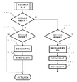
図3は、本発明の第1の実施形態で行われる設備保護洗浄の動作を示すフローチャートである。
Next, the operation of the equipment protection cleaning performed in the first embodiment of the present invention will be described.
FIG. 3 is a flowchart showing the operation of equipment protection cleaning performed in the first embodiment of the present invention.
ステップS100において、制御装置30は、初回時の設備保護洗浄であるか否かの判定を行う。
初回時の設備保護洗浄である場合はステップS110へ進み、2回目以降である場合はステップS120へ進む。
In step S100, the
If it is the equipment protection cleaning at the first time, the process proceeds to step S110, and if it is the second and subsequent times, the process proceeds to step S120.
ステップS110において、制御装置30は、タイマー1がステップS02で決定した時間T1を経過したか否かを判定する。
経過したと判定された場合(S110:Yes)は、ステップS111に進み、経過していないと判定された場合(S110:No)は、設備保護洗浄のフローを繰り返す。
In step S110, the
If it is determined that the lapse has passed (S110: Yes), the process proceeds to step S111, and if it is determined that the lapse has not passed (S110: No), the flow of equipment protection cleaning is repeated.
ステップS111において、制御装置30は、初回時の設備保護洗浄を開始させる。
具体的には、制御装置30は、給水装置40(電磁弁)を開き、大便器50へ洗浄水の吐水を行う。
In step S111, the
Specifically, the
ステップS112において、制御装置30は、タイマー1をストップさせる。
In step S112, the
ステップS113において、制御装置30は、一定時間間隔ごとに行われる設備保護洗浄の時間T2を計時するためのタイマー2をスタートさせる。
ここで、タイマー2は一定時間間隔として4時間に設定されている。
In step S113, the
Here, the timer 2 is set to 4 hours as a fixed time interval.
ステップS120において、制御装置30は、タイマー2がT2を経過したか否かを判定する。
経過したと判定された場合(S120:Yes)は、ステップS121に進み、経過していないと判定された場合(S120:No)は、設備保護洗浄のフローを繰り返す。
In step S120, the
If it is determined that the lapse has passed (S120: Yes), the process proceeds to step S121, and if it is determined that the lapse has not passed (S120: No), the flow of equipment protection cleaning is repeated.
ステップS121において、制御装置30は、2回目以降の設備保護洗浄を開始する。具体的には、制御装置30は、給水装置40(電磁弁)を開き、大便器50へ洗浄水の吐水を行う。
In step S121, the
ステップS122において、制御装置30は、タイマー2のリスタートを行う。
In step S122, the
続いて、本発明の第2の実施形態で行われる初回時設備保護洗浄開始タイミングを設定する動作について説明する。
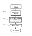
図4は、本発明の第2の実施形態で行われる初回時設備保護洗浄開始タイミングを設定する動作を示すフローチャートである。
本発明の第2の実施形態で行われる設備保護洗浄の動作は、本発明の第1の実施形態で行われる図3に示す動作と同じ動作であるので、説明を省略する。
Subsequently, the operation of setting the initial equipment protection cleaning start timing performed in the second embodiment of the present invention will be described.
FIG. 4 is a flowchart showing an operation of setting the initial equipment protection cleaning start timing performed in the second embodiment of the present invention.
Since the operation of the equipment protection cleaning performed in the second embodiment of the present invention is the same operation as the operation shown in FIG. 3 performed in the first embodiment of the present invention, the description thereof will be omitted.
本発明の第1の実施形態で行われる初回時設備保護洗浄開始タイミングを設定する動作は、乱数発生手段32による乱数Rを利用したが、本発明の第2の実施形態では、使用者が大便器50を使用する回数を利用する。
衛生設備機器1への電源投入後、まず、使用者の大便器50への使用回数Nを0回とし、制御装置30内部のタイマー3(図示せず)により、経過時間を計時する。
The operation of setting the initial equipment protection cleaning start timing performed in the first embodiment of the present invention uses the random number R by the random number generating means 32, but in the second embodiment of the present invention, the user is large. Use the number of times the
After the power is turned on to the
ステップS10において、制御装置30は、タイマー3の経過時間が1時間を越えたか否かを判定する。
経過時間を越えたと判定された場合(S10:Yes)は、ステップS11に進み、越えていないと判定された場合(S10:No)は、ステップS06を繰り返す。
In step S10, the
If it is determined that the elapsed time has been exceeded (S10: Yes), the process proceeds to step S11, and if it is determined that the elapsed time has not been exceeded (S10: No), step S06 is repeated.
ステップS11において、制御装置30は、マイコンに記憶されている1時間以内の使用者による大便器50の使用回数Nを読み込む。
In step S11, the
ステップS12において、制御装置30は、ステップS11により読み込んだ使用回数Nに基づいて、初回時の洗浄までの時間T1′を以下の式で決定する。
T1′=60−(N×5)(分)
なお、初回時の洗浄までの時間T1′がマイナスとなる場合は一律0分とする。
In step S12, the
T1'= 60- (N x 5) (minutes)
If the time T1'before cleaning at the first time is negative, it is uniformly set to 0 minutes.
そのため、大便器50の使用回数Nが多い場合には、初回時における設備保護洗浄までの時間が早くなる。
従って、使用回数Nが多く排水配管に汚物が停留する可能性が高い衛生設備機器1においては、他の衛生設備機器1より早い時間で設備保護洗浄を行うことができ、効率が良い。
Therefore, when the number of times N of the
Therefore, in the
ステップS13において、制御装置30は、ステップS11で決定した時間T1′を計時するためのタイマー1をスタートする。
In step S13, the
続いて、本発明の第3の実施形態で行われる初回時設備保護洗浄開始タイミングを設定する動作について説明する。
図5は、本発明の第3の実施形態で行われる初回時設備保護洗浄開始タイミングを設定する動作を示すフローチャートである。
本発明の第3の実施形態で行われる設備保護洗浄の動作は、本発明の第1の実施形態で行われる図3に示す動作と同じ動作であるので、説明を省略する。
Subsequently, the operation of setting the initial equipment protection cleaning start timing performed in the third embodiment of the present invention will be described.
FIG. 5 is a flowchart showing an operation of setting the initial equipment protection cleaning start timing performed in the third embodiment of the present invention.
Since the operation of the equipment protection cleaning performed in the third embodiment of the present invention is the same operation as the operation shown in FIG. 3 performed in the first embodiment of the present invention, the description thereof will be omitted.
本発明の第1の実施形態で行われる初回時設備保護洗浄開始タイミングを設定する動作は、乱数発生手段による乱数Rを利用したが、本発明の第3の実施形態では、リモコンの送信コード種別(0〜20)を利用する。 The operation of setting the initial equipment protection cleaning start timing performed in the first embodiment of the present invention uses the random number R by the random number generating means, but in the third embodiment of the present invention, the transmission code type of the remote controller Use (0 to 20).
まず、ステップS20において、制御装置30は、リモコン本体のコードCを読み出す。
具体的には、衛生設備機器1は、操作部20と制御装置30とが共通の識別情報を記憶している。そして、トイレルームに設けられている複数の衛生設備機器1は、それぞれ異なる識別情報を記憶している。つまり、衛生設備機器1ごとにリモコン本体のコードCは異なる。この識別情報である本体のコードCを読み出している。
First, in step S20, the
Specifically, in the
ステップS21では、ステップS20により読み出した本体のコードCに基づいて、初回時の設備保護洗浄までの時間T1を下記式によりを決定する。
T1′′=120―(C×5)(分)
In step S21, the time T1 until the equipment protection cleaning at the first time is determined by the following formula based on the code C of the main body read in step S20.
T1 ″ = 120- (C × 5) (minutes)
そのため、パブリックの現場において、トイレルーム内の衛生設備機器1への通電開始タイミング(ブレーカー投入)が同じ場合においても、各衛生設備機器1において、通電開始タイミングが一致することがなくなり、複数の衛生設備機器1から同時(給水タイミングが僅かでも被る場合を含む)に給水が行われることによる大便器50に給水される洗浄水の動水圧力や、衛生設備機器1ごとの排水が同一排水管70で行われた場合における排水の合流による排水量の局地的な増加、に起因する不具合を防ぐことができる。
Therefore, even if the energization start timing (breaker is turned on) to the
ステップS22では、ステップS02で決定した時間T1を計時するためのタイマーT1をスタートする。
ここで、タイマーT1は0秒から開始する。
In step S22, the timer T1 for timing the time T1 determined in step S02 is started.
Here, the timer T1 starts from 0 seconds.
以上、本発明の実施の形態について説明した。しかし、本発明はこれらの記述に限定さ
れるものではない。前述の実施の形態に関して、当業者が適宜設計変更を加えたものも、
本発明の特徴を備えている限り、本発明の範囲に包含される。例えば、使用者による大便器50への着座時間を変数発生手段として利用するなど、制御装置30が備える変数発生手段などは、例示したものに限定されるわけではなく適宜変更することができる。
The embodiments of the present invention have been described above. However, the present invention is not limited to these descriptions. Those skilled in the art with appropriate design changes regarding the above-described embodiment may also be used.
As long as it has the features of the present invention, it is included in the scope of the present invention. For example, the variable generation means included in the
1 衛生設備機器、 10 人体検知センサ、 20 操作部、 30 制御装置、32 乱数発生手段、 40 給水装置、 50 大便器、 60 給水源、 70 排水管、 T1・T1′・T1′′ 初回時の設備保護洗浄までの設定時間、 R 乱数、 N 使用回数、 C 本体のコード 1 Sanitary equipment, 10 Human body detection sensor, 20 Operation unit, 30 Control device, 32 Random number generator, 40 Water supply device, 50 Toilet bowl, 60 Water supply source, 70 Drain pipe, T1 ・ T1 ′ ・ T1 ″ Set time until equipment protection cleaning, R random number, N number of uses, C main unit code
Claims (2)
前記便器本体に洗浄水を供給する電気的に制御された給水装置と、
前記給水装置に対して一定時間の間隔で駆動を指示する制御装置と、を有する衛生設備
機器において、
前記制御装置は、所定条件により、前記制御装置の電源投入後における初回時の前記給
水装置の駆動タイミングを前記一定時間から変更させ、
前記所定条件は、前記電源投入後からの前記便器本体の使用履歴であることを特徴とする衛生設備機器。 Toilet bowl body and
An electrically controlled water supply device that supplies wash water to the toilet bowl body,
In a sanitary equipment having a control device for instructing the water supply device to be driven at regular time intervals.
The control device changes the drive timing of the water supply device at the first time after the power of the control device is turned on from the fixed time according to a predetermined condition .
The sanitary equipment, characterized in that the predetermined condition is the usage history of the toilet bowl body after the power is turned on.
前記便器本体に洗浄水を供給する電気的に制御された給水装置と、An electrically controlled water supply device that supplies wash water to the toilet bowl body,
前記給水装置に対して一定時間の間隔で駆動を指示する制御装置と、を有する衛生設備Sanitary equipment having a control device that instructs the water supply device to be driven at regular time intervals.
機器において、In the equipment
前記制御装置は、所定条件により、前記制御装置の電源投入後における初回時の前記給According to predetermined conditions, the control device is supplied with the first time after the power of the control device is turned on.
水装置の駆動タイミングを前記一定時間から変更させ、By changing the drive timing of the water device from the fixed time,
前記制御装置は、使用者からの操作を受けるリモコンを有し、The control device has a remote controller that receives operations from the user.
前記所定条件は、予め設定される前記リモコンの送信コード種別であることを特徴とすThe predetermined condition is a transmission code type of the remote controller that is set in advance.
る衛生設備機器。Sanitary equipment.
Priority Applications (1)
| Application Number | Priority Date | Filing Date | Title |
|---|---|---|---|
| JP2016173612A JP6838325B2 (en) | 2016-09-06 | 2016-09-06 | Sanitary equipment |
Applications Claiming Priority (1)
| Application Number | Priority Date | Filing Date | Title |
|---|---|---|---|
| JP2016173612A JP6838325B2 (en) | 2016-09-06 | 2016-09-06 | Sanitary equipment |
Publications (2)
| Publication Number | Publication Date |
|---|---|
| JP2018040124A JP2018040124A (en) | 2018-03-15 |
| JP6838325B2 true JP6838325B2 (en) | 2021-03-03 |
Family
ID=61625136
Family Applications (1)
| Application Number | Title | Priority Date | Filing Date |
|---|---|---|---|
| JP2016173612A Active JP6838325B2 (en) | 2016-09-06 | 2016-09-06 | Sanitary equipment |
Country Status (1)
| Country | Link |
|---|---|
| JP (1) | JP6838325B2 (en) |
Family Cites Families (5)
| Publication number | Priority date | Publication date | Assignee | Title |
|---|---|---|---|---|
| JPS51140347A (en) * | 1975-05-28 | 1976-12-03 | Toto Ltd | Closet flushing device |
| JPS57137537A (en) * | 1981-02-18 | 1982-08-25 | F M Valve Mfg | Automatic washing apparatus |
| US4805247A (en) * | 1987-04-08 | 1989-02-21 | Coyne & Delany Co. | Apparatus for preventing unwanted operation of sensor activated flush valves |
| JP2007239266A (en) * | 2006-03-07 | 2007-09-20 | Inax Corp | Remote control apparatus |
| JP5704499B2 (en) * | 2009-11-10 | 2015-04-22 | Toto株式会社 | Toilet bowl cleaning device |
-
2016
- 2016-09-06 JP JP2016173612A patent/JP6838325B2/en active Active
Also Published As
| Publication number | Publication date |
|---|---|
| JP2018040124A (en) | 2018-03-15 |
Similar Documents
| Publication | Publication Date | Title |
|---|---|---|
| US6000429A (en) | Device for controlling a series of washroom appliances | |
| KR940006229Y1 (en) | Charge cutting preventing apparatus of storage battery | |
| US10478027B2 (en) | Toilet seat device and toilet device equipped therewith | |
| PL176291B1 (en) | Method of automatically initiating a flushing process | |
| JP2006299726A (en) | Toilet bowl flushing device and method for detecting clogging of drainage pipe | |
| JP6838325B2 (en) | Sanitary equipment | |
| JP2009221795A (en) | Water supply device | |
| JP2018031141A (en) | Toilet system | |
| JP5605677B2 (en) | Heating toilet seat device | |
| JP2017089957A (en) | Ventilation device | |
| KR20200017957A (en) | System for removing smell of toilet and Method of this | |
| JP2014194387A (en) | Human body detection sensor | |
| JP2009086747A (en) | Controller and toilet device having the same | |
| JP2847464B2 (en) | Water supply control device | |
| JP7161697B2 (en) | Toilet clogging detector | |
| JP2002048877A (en) | Body detecting device | |
| JP2001004760A (en) | Presence-detecting device and sanitary washing device using the same | |
| KR20110064929A (en) | Washing system of urinal | |
| KR100844609B1 (en) | Clogging detecting method for dryer | |
| JP2005264638A (en) | Automatic hand washing and sterilizing device | |
| JP4349175B2 (en) | Ventilation equipment | |
| JP2012233610A (en) | Ventilation device | |
| JP2018159199A (en) | Sanitary washing device | |
| JPH10307974A (en) | Water leakage detecting device | |
| KR20210092585A (en) | Coocker and operating method thereof |
Legal Events
| Date | Code | Title | Description |
|---|---|---|---|
| A621 | Written request for application examination |
Free format text: JAPANESE INTERMEDIATE CODE: A621 Effective date: 20190828 |
|
| A977 | Report on retrieval |
Free format text: JAPANESE INTERMEDIATE CODE: A971007 Effective date: 20200710 |
|
| A131 | Notification of reasons for refusal |
Free format text: JAPANESE INTERMEDIATE CODE: A131 Effective date: 20200720 |
|
| A521 | Written amendment |
Free format text: JAPANESE INTERMEDIATE CODE: A523 Effective date: 20200910 |
|
| TRDD | Decision of grant or rejection written | ||
| A01 | Written decision to grant a patent or to grant a registration (utility model) |
Free format text: JAPANESE INTERMEDIATE CODE: A01 Effective date: 20210112 |
|
| A61 | First payment of annual fees (during grant procedure) |
Free format text: JAPANESE INTERMEDIATE CODE: A61 Effective date: 20210125 |
|
| R150 | Certificate of patent or registration of utility model |
Ref document number: 6838325 Country of ref document: JP Free format text: JAPANESE INTERMEDIATE CODE: R150 |