JP6836076B2 - Information processing equipment, its control method, and programs - Google Patents
Information processing equipment, its control method, and programs Download PDFInfo
- Publication number
- JP6836076B2 JP6836076B2 JP2017253072A JP2017253072A JP6836076B2 JP 6836076 B2 JP6836076 B2 JP 6836076B2 JP 2017253072 A JP2017253072 A JP 2017253072A JP 2017253072 A JP2017253072 A JP 2017253072A JP 6836076 B2 JP6836076 B2 JP 6836076B2
- Authority
- JP
- Japan
- Prior art keywords
- video
- image
- resolution
- acquisition
- network camera
- Prior art date
- Legal status (The legal status is an assumption and is not a legal conclusion. Google has not performed a legal analysis and makes no representation as to the accuracy of the status listed.)
- Active
Links
Images


Description
本発明は、情報処理装置、及びその制御方法、プログラムに関し、特に、ネットワークカメラが撮影した複数の異なる解像度の映像の管理を容易にするための技術に関する。 The present invention relates to an information processing device, a control method thereof, and a program thereof, and more particularly to a technique for facilitating management of a plurality of images of different resolutions taken by a network camera.
従来、鉄道の保線作業を行う方法として、電車を走行させて、線路等を確認する方法が知られている。 Conventionally, as a method of performing track maintenance work of a railway, a method of running a train and checking a track or the like is known.
特許文献1には、検測車の先頭等に設けられたカメラで走行路線をモニタリングすることが提案されている。
しかしながら、例えば、保線業務を行う者(ユーザ)が、社屋内(車両以外の場所)で、電車等の先頭車両に設けられたカメラで撮影されたライブ映像を確認して保線業務を行う場合、当該カメラで撮影されたライブ映像をネットワーク上の録画サーバや当該ユーザの端末に、例えばLTE等の通信網を用いて送信することが考えられる。 However, for example, when a person (user) who performs track maintenance work confirms a live image taken by a camera installed in a leading vehicle such as a train inside the company (a place other than a vehicle) and performs track maintenance work. It is conceivable to transmit the live video captured by the camera to a recording server on the network or the terminal of the user using a communication network such as LTE.
この場合、当該ユーザが、ディスプレイに表示された映像を確認して行う保線業務には、高解像度の映像が必要となるが、当該カメラで撮影された高解像度の映像をライブで送信することは、例えばLTE等の通信網の帯域では難しい。 In this case, a high-resolution image is required for the track maintenance work performed by the user by checking the image displayed on the display, but the high-resolution image taken by the camera cannot be transmitted live. For example, it is difficult in the band of a communication network such as LTE.
そこで、ネットワークカメラが低解像度のライブ映像をライブで録画サーバやユーザの端末に送信し、ユーザは、低解像度の映像をライブで確認し、詳細に確認すべき個所があれば、高解像度の映像を確認することが考えられる。 Therefore, the network camera sends the low-resolution live video live to the recording server or the user's terminal, and the user checks the low-resolution video live, and if there is a place to check in detail, the high-resolution video. It is conceivable to confirm.
この場合、当該ネットワークカメラで撮影された高解像度の映像を、当該ネットワークカメラに接続された車両内の情報処理装置の記憶領域に記録させて、当該記録された高解像度の映像を順次録画サーバに当該通信網を用いて送信することが考えられる。 In this case, the high-resolution image taken by the network camera is recorded in the storage area of the information processing device in the vehicle connected to the network camera, and the recorded high-resolution image is sequentially recorded in the recording server. It is conceivable to transmit using the communication network.
そのような仕組みにおいては、低解像度のライブ映像と、高解像度の映像の取得要求や送信で用いるポートはそれぞれ異なる。その結果、録画サーバは、低解像度の映像と高解像度の映像とがそれぞれ異なるネットワークカメラで撮影された映像と認識してしまい、低解像度の映像と高解像度の映像の両方の映像を記録することになってしまう。 In such a mechanism, the low-resolution live video and the port used for the acquisition request and transmission of the high-resolution video are different. As a result, the recording server recognizes the low-resolution image and the high-resolution image as images taken by different network cameras, and records both the low-resolution image and the high-resolution image. Become.
その結果、録画サーバのメモリ領域を多く必要としてしまうこととなり、コストが高くなってしまう。 As a result, a large amount of memory area of the recording server is required, which increases the cost.
また、低解像度のライブ映像と高解像度の映像が、それぞれ異なるネットワークカメラで撮影された映像として管理されてしまうため、ユーザは、同一のネットワークカメラで撮影された低解像度のライブ映像と高解像度の映像を容易に確認することができなかった。 In addition, since the low-resolution live image and the high-resolution image are managed as images taken by different network cameras, the user can use the low-resolution live image and the high-resolution image taken by the same network camera. The image could not be confirmed easily.
また、ユーザが、高解像度の映像を閲覧可能な時間帯や、低解像の映像を閲覧可能な時間帯を容易に把握することができなった。 In addition, it has become impossible for the user to easily grasp the time zone in which the high-resolution video can be viewed and the time zone in which the low-resolution video can be viewed.
本発明の目的は、ネットワークカメラが撮影した複数の異なる解像度の映像の管理を容易にするための仕組みを提供することである。 An object of the present invention is to provide a mechanism for facilitating management of a plurality of images of different resolutions taken by a network camera.
本発明は、ネットワークカメラが撮影した第1映像を取得する取得手段と、前記取得手段により取得した前記第1映像を記憶部に記憶する記憶手段と、を備え、前記取得手段は、前記第1映像を取得した後に、前記第1映像よりも高解像度の、前記ネットワークカメラが撮影した第2映像を取得し、前記記憶手段は、前記取得手段により取得した前記第2映像を、前記記憶部に記憶された前記第1映像に上書きし、前記第1映像と前記第2映像は、同一の前記ネットワークカメラが撮影した同一時刻又は同一時間帯の映像であることを特徴とする。
The present invention includes an acquisition unit you get the first video network camera shot, a storage means for storing in the storage unit the first image acquired by the pre-Symbol acquiring unit, the acquisition unit, the after obtaining the first image, the high-resolution than the first image to obtain a second image in which the network camera is taken, the storage unit, the second image acquired by the acquisition unit, the storage The first image stored in the unit is overwritten, and the first image and the second image are images taken by the same network camera at the same time or in the same time zone .
また、本発明は、ネットワークカメラにより撮影された第1映像がルータの第1ポートを用いてネットワークに送信され、また、前記第1映像よりも高解像度の、前記ネットワークカメラが撮影した第2映像がルータの第2ポートを用いてネットワークに送信され、前記ネットワークに送信された前記第1映像、及び前記第2映像を取得して記憶部に記憶する情報処理装置であって、前記ネットワークに送信された前記第1映像を取得する取得手段と、前記取得手段により取得された前記第1映像を前記記憶部に記憶する記憶手段と、を備え、前記取得手段は、前記第1映像を取得した後に前記第2映像を取得し、前記記憶手段は、前記第1映像の取得の際に用いた前記ルータの前記第1ポートのポート番号と、前記第2映像の取得の際に用いた前記ルータの前記第2ポートのポート番号とが、予め関連付けられて記憶されていることを条件に、当該取得した前記第2映像を、前記第1映像に関する映像として記憶する処理を行い、前記第1映像と前記第2映像は、同一の前記ネットワークカメラが撮影した同一時刻又は同一時間帯の映像であることを特徴とする。
また、本発明は、ネットワークカメラが撮影した第1映像を取得する取得手段と、前記取得手段により取得した前記第1映像を記憶部に記憶する記憶手段と、を備え、前記取得手段は、前記第1映像を取得した後に、前記第1映像よりも高解像度の、前記ネットワークカメラが撮影した第2映像を取得し、前記記憶手段は、前記取得手段により前記第2映像を取得したことに応じて、前記取得手段で取得した前記第2映像を、前記記憶部に記憶された前記第1映像に関する映像として記憶する処理、及び前記第1映像を消す処理を行い、前記第1映像と前記第2映像は、同一の前記ネットワークカメラが撮影した同一時刻又は同一時間帯の映像であることを特徴とする。
Further, in the present invention, the first image taken by the network camera is transmitted to the network using the first port of the router, and the second image taken by the network camera has a higher resolution than the first image. Is an information processing device that is transmitted to a network using the second port of the router, acquires the first video and the second video transmitted to the network, and stores them in a storage unit, and transmits the second video to the network. The acquisition means includes an acquisition means for acquiring the first video, and a storage means for storing the first video acquired by the acquisition means in the storage unit, and the acquisition means has acquired the first video. Later, the second video was acquired, and the storage means used the port number of the first port of the router used when acquiring the first video and the router used when acquiring the second video. On the condition that the port number of the second port is stored in association with each other in advance, the acquired second video is stored as a video related to the first video, and the first video is stored. the second image and the same of the network camera, wherein the Ru video der the same time or the same time period were taken.
Further, the present invention includes an acquisition unit you get the first video network camera is captured, and a storage means for storing the first image in the storage unit acquired by the pre-Symbol acquisition means, said acquisition means , after acquiring the first image, said high-resolution than the first image to obtain a second image in which the network camera is captured, wherein the storage unit, which obtains the second image by the acquisition unit depending on, the second image obtained in the previous SL acquisition means, processing of storing a picture for the first image stored in the storage unit, and performs processing to erase the first image, the first image the second image and the same of the network camera, wherein the video der Rukoto the same time or the same time period were taken.
また、本発明は、情報処理装置における制御方法であって、ネットワークカメラが撮影した第1映像を取得する取得工程と、前記取得工程により取得した前記第1映像を記憶部に記憶する記憶工程と、を備え、前記取得工程は、前記第1映像を取得した後に、前記第1映像よりも高解像度の、前記ネットワークカメラが撮影した第2映像を取得し、前記記憶工程は、前記取得工程により取得した前記第2映像を、前記記憶部に記憶された前記第1映像に上書きし、前記第1映像と前記第2映像は、同一の前記ネットワークカメラが撮影した同一時刻又は同一時間帯の映像であることを特徴とする。 Further, the present invention is a control method in an information processing apparatus, which includes an acquisition step of acquiring a first image captured by a network camera and a storage step of storing the first image acquired by the acquisition step in a storage unit. After acquiring the first image, the acquisition step acquires a second image taken by the network camera having a resolution higher than that of the first image, and the storage process is performed by the acquisition step. The acquired second image is overwritten with the first image stored in the storage unit, and the first image and the second image are images taken by the same network camera at the same time or in the same time zone. It is characterized by being.
また、本発明は、ネットワークカメラにより撮影された第1映像がルータの第1ポートを用いてネットワークに送信され、また、前記第1映像よりも高解像度の、前記ネットワークカメラが撮影した第2映像がルータの第2ポートを用いてネットワークに送信され、前記ネットワークに送信された前記第1映像、及び前記第2映像を取得して記憶部に記憶する情報処理装置における制御方法であって、前記ネットワークに送信された前記第1映像を取得する取得工程と、前記取得工程により取得された前記第1映像を前記記憶部に記憶する記憶工程と、を備え、前記取得工程は、前記第1映像を取得した後に前記第2映像を取得し、前記記憶工程は、前記第1映像の取得の際に用いた前記ルータの前記第1ポートのポート番号と、前記第2映像の取得の際に用いた前記ルータの前記第2ポートのポート番号とが、予め関連付けられて記憶されていることを条件に、当該取得した前記第2映像を、前記第1映像に関する映像として記憶する処理を行い、前記第1映像と前記第2映像は、同一の前記ネットワークカメラが撮影した同一時刻又は同一時間帯の映像であることを特徴とする。
また、本発明は、情報処理装置における制御方法であって、ネットワークカメラが撮影した第1映像を取得する取得工程と、前記取得工程により取得した前記第1映像を記憶部に記憶する記憶工程と、を備え、前記取得工程は、前記第1映像を取得した後に、前記第1映像よりも高解像度の、前記ネットワークカメラが撮影した第2映像を取得し、前記記憶工程は、前記取得工程により前記第2映像を取得したことに応じて、前記取得工程で取得した前記第2映像を、前記記憶部に記憶された前記第1映像に関する映像として記憶する処理、及び前記第1映像を消す処理を行い、前記第1映像と前記第2映像は、同一の前記ネットワークカメラが撮影した同一時刻又は同一時間帯の映像であることを特徴とする。
Further, in the present invention, the first image taken by the network camera is transmitted to the network using the first port of the router, and the second image taken by the network camera has a higher resolution than the first image. Is a control method in an information processing device that acquires the first video and the second video transmitted to the network using the second port of the router and stores the second video in a storage unit. The acquisition step includes an acquisition step of acquiring the first video transmitted to the network and a storage step of storing the first video acquired by the acquisition step in the storage unit, and the acquisition step is the first video. The second video is acquired after the acquisition of the above, and the storage step is used when the port number of the first port of the router used when acquiring the first video and when the second video is acquired. On the condition that the port number of the second port of the router that has been used is stored in association with each other in advance, the acquired second video is stored as a video related to the first video, and the process is performed. The first image and the second image are characterized by being images taken by the same network camera at the same time or in the same time zone.
Further, the present invention is a control method in an information processing apparatus, which includes an acquisition step of acquiring a first image captured by a network camera and a storage step of storing the first image acquired by the acquisition step in a storage unit. After acquiring the first image, the acquisition step acquires a second image captured by the network camera having a resolution higher than that of the first image, and the storage process is performed by the acquisition step. A process of storing the second image acquired in the acquisition step as an image related to the first image stored in the storage unit and a process of erasing the first image in response to the acquisition of the second image. The first image and the second image are images taken by the same network camera at the same time or in the same time zone.
また、本発明は、コンピュータを、上述の情報処理装置として機能させるためのプログラムを特徴とする。
Further, the present invention causes a computer, characterized by a program for functioning in the above-described information processing apparatus.
本発明によれば、ネットワークカメラが撮影した複数の異なる解像度の映像の管理を容易にすることができる。 According to the present invention, it is possible to easily manage a plurality of images having different resolutions taken by a network camera.
以下、図面を参照して、本発明の実施形態を詳細に説明する。 Hereinafter, embodiments of the present invention will be described in detail with reference to the drawings.
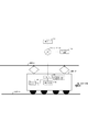
図1は、本発明の情報処理システムのシステム構成の一例を示すである。 FIG. 1 shows an example of a system configuration of the information processing system of the present invention.
図1では、電車102が、架線101から供給される電力を用いて線路103上を走行する鉄道を一例として説明するが、他の鉄道の形態であってもよいし、鉄道の形態でなくてもよい。 In FIG. 1, a railway in which the train 102 travels on the railroad track 103 using the electric power supplied from the overhead wire 101 will be described as an example, but it may be in the form of another railway or not in the form of a railway. May be good.
図1に示す情報処理システムは、ネットワークカメラ1(105)、情報処理装置104、ルータ106、録画サーバ107、クライアント端末108を備えている。
The information processing system shown in FIG. 1 includes a network camera 1 (105), an information processing device 104, a
電車102は、ルータ106と、ネットワークカメラ1(105)と、情報処理装置104とを備えている。
The train 102 includes a
ネットワークカメラ1(105)と、情報処理装置104は、ルータ106を介して相互に通信可能に接続されている。
The network camera 1 (105) and the information processing device 104 are connected to each other via a
また、ネットワークカメラ1(105)と、情報処理装置104は、ルータ106を介してインターネット等のネットワーク110と通信可能に接続されている。
Further, the network camera 1 (105) and the information processing device 104 are communicably connected to a network 110 such as the Internet via a
ルータ106は、例えば、LTEルータであり、グローバルIPアドレスとして「A」が設定されており、ネットワークカメラ1の低解像度のライブ映像を録画サーバ107に送信するために用いられるポートのポート番号として「1」が設定されている。また、ネットワークカメラ1の高解像度の映像を録画サーバ107に送信するために用いられるポートのポート番号として「2」が設定されている。
The
また、例えば、ネットワークカメラ1(105)と、情報処理装置104とを1つの筐体にして1つの情報処理装置又はネットワークカメラとすることもできる。 Further, for example, the network camera 1 (105) and the information processing device 104 can be combined into one housing to form one information processing device or network camera.
ネットワークカメラ1(105)は、電車の車両の先頭車両に設置されており、車両の進行方向の前方を撮影するように設けられている。 The network camera 1 (105) is installed in the leading car of the train car, and is provided so as to photograph the front in the traveling direction of the car.
録画サーバ107は、ネットワークカメラ1(105)からルータ106を介して送信される映像(低解像度のライブ映像の動画データ)を受信して録画する機能、当該映像をクライアント端末108に送信する機能を備えている。
The
また、録画サーバ107は、情報処理装置104からルータ106を介して送信される映像(高解像度の動画データ)を受信して録画する機能、当該映像をクライアント端末108に送信する機能を備えている。
Further, the
録画サーバ107は、ネットワーク110と相互に通信可能に接続されており、ネットワーク110と通信可能なクライアント端末108、ルータ106と相互に通信可能に接続されている。
The
ネットワークカメラ1(105)は、録画サーバ107からのライブ映像の取得要求を受信すると、当該ライブ映像の動画データ(低解像度のライブ映像)を、ルータ106を介して録画サーバ107に送信する。録画サーバ107は、当該低解像度のライブ映像を受信すると、当該ライブ映像をメモリに記憶する。
When the network camera 1 (105) receives the live video acquisition request from the
また、ネットワークカメラ1(105)は、低解像度のライブ映像を、ルータ106を介して録画サーバ107に送信すると共に、当該映像と同一画角で当該映像よりも高解像度の映像の動画データを情報処理装置104に送信する。
Further, the network camera 1 (105) transmits a low-resolution live video to the
すなわち、第1映像(低解像度のライブ映像)と第2映像(高解像度の映像)は、同一のネットワークカメラが撮影した同一時刻又は同一時間帯の映像である。第1映像は、ライブ映像として表示部に表示される映像である。 That is, the first video (low-resolution live video) and the second video (high-resolution video) are videos taken by the same network camera at the same time or in the same time zone. The first image is an image displayed on the display unit as a live image.
情報処理装置104は、高解像度の映像を記憶するSSD等のメモリ(外部メモリ211)を備えており、ネットワークカメラ1(105)から高解像度の映像(動画データ)を受信すると、当該映像を当該メモリに記憶する。そして、所定時間分の映像が記憶され、かつ、録画サーバ107から送信された当該高解像度の映像の取得要求を受け付けると、その映像を1つの動画ファイルとし、ルータ106を介して、録画サーバ107に送信する。
The information processing device 104 is provided with a memory (external memory 211) such as an SSD that stores a high-resolution image, and when the high-resolution image (moving image data) is received from the network camera 1 (105), the image is displayed. Store in memory. Then, when the video for a predetermined time is stored and the acquisition request for the high-resolution video transmitted from the
そして、録画サーバ107は、当該高解像度の映像を受信すると、同一のカメラで撮影された低解像度のライブ映像を上書き登録する。
Then, when the
録画サーバ107は、録画サーバ107が受信した低解像度のライブ映像、及び高解像度の映像をクライアント端末108に送信し、クライアント端末108は、録画サーバ107から送信される映像(低解像度のライブ映像、高解像度の映像)を受信して表示する機能を備えている。
The
図2は、図1に示す録画サーバ107、クライアント端末108、及び情報処理装置104に適用可能な情報処理装置のハードウェア構成の一例を示すブロック図である。
FIG. 2 is a block diagram showing an example of a hardware configuration of an information processing device applicable to the
図2に示すように、情報処理装置は、システムバス204を介してCPU(Central Processing Unit)201、ROM(Read Only Memory)203、RAM(Random Access Memory)202、入力コントローラ205、ビデオコントローラ206、メモリコントローラ207、および通信I/Fコントローラ208が接続される。
As shown in FIG. 2, the information processing apparatus includes a CPU (Central Processing Unit) 201, a ROM (Read Only Memory) 203, a RAM (Random Access Memory) 202, an
CPU201は、システムバス204に接続される各デバイスやコントローラを統括的に制御する。
The
ROM203あるいは外部メモリ211等の記憶装置は、CPU201が実行する制御プログラムであるBIOS(Basic Input/Output System)やOS(Operating System)や、本情報処理方法を実現するためのコンピュータ読み取り実行可能なプログラムおよび必要な各種データ(データテーブルを含む)を保持している。
The storage device such as the
RAM202は、CPU201の主メモリ、ワークエリア等として機能する。CPU201は、処理の実行に際して必要なプログラム等をROM203あるいは外部メモリ211からRAM202にロードし、ロードしたプログラムを実行することで各種動作を実現する。
The
入力コントローラ205は、入力装置209(入力デバイス)からの入力を制御する。入力装置209としては、キーボード、タッチパネル、マウス等のポインティングデバイス等が挙げられる。
The
なお、入力装置209がタッチパネルの場合、ユーザがタッチパネルに表示されたアイコンやカーソルやボタンに合わせて押下(指等でタッチ)することにより、各種の指示を行うことができることとする。
When the
また、タッチパネルは、マルチタッチスクリーンなどの、複数の指でタッチされた位置を検出することが可能なタッチパネルであってもよい。 Further, the touch panel may be a touch panel such as a multi-touch screen that can detect the position touched by a plurality of fingers.
ビデオコントローラ206は、ディスプレイ装置210などの外部出力装置への表示を制御する。ディスプレイは本体と一体になったノート型パソコンのディスプレイも含まれるものとする。なお、外部出力装置はディスプレイに限ったものははく、例えばプロジェクタであってもよい。また、前述のタッチ操作により受け付け可能な装置については、入力装置209を提供する。
The
なおビデオコントローラ206は、表示制御を行うためのビデオメモリ(VRAM)を制御することが可能で、ビデオメモリ領域としてRAM202の一部を利用することもできるし、別途専用のビデオメモリを設けることも可能である。
The
メモリコントローラ207は、外部メモリ211へのアクセスを制御する。外部メモリとしては、ブートプログラム、各種アプリケーション、フォントデータ、ユーザファイル、編集ファイル、および各種データ等を記憶する外部記憶装置(ハードディスク)、フレキシブルディスク(FD)、或いはPCMCIAカードスロットにアダプタを介して接続されるコンパクトフラッシュ(登録商標)メモリ等を利用可能である。
The
通信I/Fコントローラ208は、ネットワークを介して外部機器と接続・通信するものであり、ネットワークでの通信制御処理を実行する。例えば、TCP/IPを用いた通信、Wi−Fi、および3G回線、LTE回線を用いた通信が可能である。
The communication I /
なお、外部メモリ211等の記憶装置は情報を永続的に記憶するための媒体であって、その形態をハードディスク等の記憶装置に限定するものではない。例えば、SSD(Solid State Drive)などの媒体であってもよい。
A storage device such as the
また本実施形態における通信端末で行われる各種処理時の一時的なメモリエリアとしても利用可能である。 It can also be used as a temporary memory area during various processes performed by the communication terminal in this embodiment.
尚、CPU201は、例えばRAM202内の表示情報用領域へアウトラインフォントの展開(ラスタライズ)処理を実行することにより、ディスプレイ装置210上での表示を可能としている。また、CPU201は、ディスプレイ装置210上の不図示のマウスカーソル等でのユーザ指示を可能とする。
The
次に、図7のフローチャートを用いて、ネットワークカメラ1(105)、情報処理装置104、録画サーバ107、クライアント端末108が実行する処理について説明する。
Next, the processes executed by the network camera 1 (105), the information processing device 104, the
図7は、ネットワークカメラ1(105)が撮影した低解像度のライブ映像の記録、及び表示処理、ネットワークカメラ1(105)が撮影した高解像度の映像の記録処理の一例を示すフローチャートである。 FIG. 7 is a flowchart showing an example of recording and display processing of a low-resolution live image taken by the network camera 1 (105) and recording processing of a high-resolution image taken by the network camera 1 (105).
図7に示すS701〜S704に示す処理は、ネットワークカメラ1(105)のCPUがプログラムを読み出して実行することにより実現される。 The processes shown in S701 to S704 shown in FIG. 7 are realized by the CPU of the network camera 1 (105) reading and executing the program.
また、図7に示すS705〜S708に示す処理は、クライアント端末108のCPU201がプログラムを読み出して実行することにより実現される。
Further, the processes shown in S705 to S708 shown in FIG. 7 are realized by the
また、図7に示すS709〜S713、S717〜S720に示す処理は、録画サーバ107のCPU201がプログラムを読み出して実行することにより実現される。
Further, the processes shown in S709 to S713 and S717 to S720 shown in FIG. 7 are realized by the
また、図7に示すS714〜S716に示す処理は、情報処理装置104のCPU201がプログラムを読み出して実行することにより実現される。
Further, the processes shown in S714 to S716 shown in FIG. 7 are realized by the
録画サーバ107は、低解像度のライブ映像の取得要求を行う要求先として、ルータ106のIPアドレス「A」(グローバルIPアドレス)と、低解像度用のポート番号「1」との組み合わせの情報(単に、低解像度のカメラのアドレスとも言う)を記憶しており、また、高解像度の映像の取得要求を行う要求先として、ルータ106のIPアドレス「A」(グローバルIPアドレス)と、高解像度用のポート番号「2」との組み合わせの情報(単に、高解像度のカメラのアドレスとも言う)を記憶している。
The
まず、録画サーバ107は、タイマー機能を備えており、所定の時間になると、ネットワークカメラ1(105)が撮影するライブ映像の取得要求を、ルータ106を介して、ネットワークカメラ1(105)に対して行う。このとき、録画サーバ107は、低解像度のカメラのアドレス(A:1)に対して当該取得要求を送信する。ルータ106は、低解像度のカメラのアドレス(A:1)で当該取得要求を受信すると、ネットワークカメラ1(105)に対して当該取得要求を送信する。
First, the
ネットワークカメラ1(105)は、当該取得要求を受信すると、車両の進行方向の前方方向を撮影し、当該撮影して得られた映像を取得する。ここで、ネットワークカメラ1(105)は、低解像度の映像(動画データ)として、例えば、VGAの解像度の動画データを取得する(S701)。この低解像度の映像は、録画映像用だけではなくライブ映像用の動画データとしても用いられる。 Upon receiving the acquisition request, the network camera 1 (105) photographs the vehicle in the forward direction in the traveling direction and acquires the captured image. Here, the network camera 1 (105) acquires, for example, VGA resolution moving image data as low-resolution video (moving image data) (S701). This low-resolution video is used not only for recorded video but also as video data for live video.
また、ネットワークカメラ1(105)は、当該低解像度の映像と同じ画角の高解像度の映像(動画データ)として、例えば、HDの解像度の動画データを取得する(S703)。 Further, the network camera 1 (105) acquires, for example, HD resolution moving image data as a high resolution image (moving image data) having the same angle of view as the low resolution image (S703).
そして、ネットワークカメラ1(105)は、S701で取得した低解像度の映像を録画サーバ107に送信する(S702)。具体的には、ネットワークカメラ1(105)は、S701で取得した低解像度の映像をルータ106に送信し、当該ルータ106は、低解像度のカメラのアドレス(A:1)のポートから、当該低解像度の映像を録画サーバ107に送信する。また、S702では、当該低解像度を示す情報(例えば、VGA(低解像度))も録画サーバ107に送信される。
Then, the network camera 1 (105) transmits the low-resolution video acquired in S701 to the recording server 107 (S702). Specifically, the network camera 1 (105) transmits the low-resolution video acquired in S701 to the
また、ネットワークカメラ1(105)は、S703で取得した高解像度の映像を情報処理装置104に送信する(S704)。また、S704では、当該映像(動画データ)の解像度を示す情報として、高解像度を示す情報(例えば、HD(高解像度))が情報処理装置104に送信される。 Further, the network camera 1 (105) transmits the high-resolution video acquired in S703 to the information processing device 104 (S704). Further, in S704, information indicating high resolution (for example, HD (high resolution)) is transmitted to the information processing apparatus 104 as information indicating the resolution of the video (moving image data).
そして、ネットワークカメラ1(105)は、処理をS701、S703に戻して、同様の処理を繰り返し実行する。 Then, the network camera 1 (105) returns the process to S701 and S703, and repeatedly executes the same process.
ネットワークカメラ1(105)は、S701及びS702の処理と、S703及びS704の処理を並行して処理する。
情報処理装置104は、S704で送信された高解像度の映像を受信(取得)すると(S714)、当該取得した映像をSSD等のメモリ(外部メモリ211)に一時記憶(記録)する(S715)。S714では、当該高解像度を示す情報(例えば、HD(高解像度))も受信する。
The network camera 1 (105) processes the processes of S701 and S702 and the processes of S703 and S704 in parallel.
When the information processing device 104 receives (acquires) the high-resolution video transmitted in S704 (S714), the information processing device 104 temporarily stores (records) the acquired video in a memory (external memory 211) such as an SSD (S715). In S714, information indicating the high resolution (for example, HD (high resolution)) is also received.
そして、情報処理装置104は、S715で所定時間分(例えば、10分分)の映像が一時記録されると、当該映像を1つの動画ファイルとして、ルータ106を介して、録画サーバ107に送信する(S716)。このとき、高解像度のカメラのアドレスも録画サーバ107に送信する。
Then, when the video for a predetermined time (for example, 10 minutes) is temporarily recorded in S715, the information processing device 104 transmits the video as one video file to the
具体的には、録画サーバ107は、ライブ映像の取得要求を行うと、常時、情報処理装置104に対して、高解像度の映像の取得要求を行う。録画サーバ107は、低解像度のカメラのアドレス(A:2)に対して高解像度の映像の取得要求を送信する。ルータ106は、高解像度のカメラのアドレス(A:2)で当該取得要求を受信すると、情報処理装置104に対して当該取得要求を送信する。そして、情報処理装置104は、当該取得要求を受信すると、高解像度の1つの動画ファイルをルータ106に対して送信し、ルータ106は、ポート番号2のポートから、録画サーバ107に対して、当該動画ファイルを送信する(S716)。
Specifically, when the
そして、情報処理装置104は、処理をS714に戻す。S716では、最も古い映像(最も昔に撮影された映像)から優先して録画サーバ107に送信する。また、S716では、当該高解像度を示す情報(例えば、HD(高解像度))も送信する。
Then, the information processing device 104 returns the process to S714. In S716, the oldest video (the oldest shot video) is preferentially transmitted to the
そのため、S717の第2映像取得手段は、ネットワークカメラにより最も過去に撮影された時間の第2映像から、順次取得する取得処理を行う。 Therefore, the second image acquisition means of S717 performs an acquisition process of sequentially acquiring the second image at the time most recently captured by the network camera.
S702で低解像度のライブ映像がネットワークカメラ1(105)から録画サーバ107に送信されるが、ここで送信される映像は、S716で送信される映像よりも低解像度の映像であるため、すなわち、S702で送信するデータ容量が、S716で送信するデータ容量よりも少ないため、S716で送信される送信時間よりも短い送信時間で送信することができる。
The low-resolution live video is transmitted from the network camera 1 (105) to the
録画サーバ107は、S702でネットワークカメラ1(105)から送信された低解像度の映像、及び低解像度を示す情報(例えば、VGA(低解像度))を受信する。このとき、ルータ106から送信されたポートを示すポート番号「1」と、ルータ106のIPアドレス「A」の組み合わされた情報(低解像度のカメラのアドレス)も受信する(S710)。
The
S710は、本発明の第1映像取得手段の適用例であり、ネットワークカメラが撮影した第1映像(低解像度のライブ映像)を取得する。 S710 is an application example of the first video acquisition means of the present invention, and acquires a first video (low-resolution live video) captured by a network camera.
そして、録画サーバ107は、当該受信した低解像度のカメラのアドレス(A:1)から、当該映像のネットワークカメラを識別するカメラIDを特定する(S710)。
Then, the
具体的には、録画サーバ107は、録画サーバ107の外部メモリ211の記憶手段に記憶されているカメラ映像管理テーブル1101(図11)を参照して、S702で受信した低解像度用のカメラのアドレス(A:1)に対応するカメラID(1)を特定する。
Specifically, the
カメラ映像管理テーブル1101は、ルータ106から低解像度の映像が送信される際に用いられるルータ106のポートの「低解像度のカメラのアドレス(低解像度用のカメラのアドレス)」と、ルータ106から高解像度の映像が送信される際に用いられるルータ106のポートの「高解像度のカメラのアドレス(高解像度用のカメラのアドレス)」と、当該低解像度の映像、及び高解像度の映像を撮影したネットワークカメラ1(105)を識別するためのカメラIDと、が互いに対応付けられて記憶されているテーブルの一例である。
The camera image management table 1101 shows the "low resolution camera address (low resolution camera address)" of the port of the
カメラ映像管理テーブル1101は、本発明の関連情報の適用例であり、第1映像取得手段で第1映像を取得する取得先(ルータ)の第1ポート(図11の例では1)と、第2映像取得手段で第2映像を取得する取得先(ルータ)の第2ポート(図11の例では2)とが関連付けられた情報である。また、このカメラ映像管理テーブル1101は、録画サーバ107のメモリなどの記憶手段(関連情報記憶手段)に記憶されている。
The camera image management table 1101 is an application example of the related information of the present invention, and is the first port (1 in the example of FIG. 11) of the acquisition destination (router) for acquiring the first image by the first image acquisition means, and the first port. 2 This is information associated with the second port (2 in the example of FIG. 11) of the acquisition destination (router) for acquiring the second image by the image acquisition means. Further, the camera image management table 1101 is stored in a storage means (related information storage means) such as a memory of the
録画サーバ107は、S710で受信した低解像度のカメラのアドレスに対応してカメラ映像管理テーブル1101に記憶されているカメラIDを特定すると、クライアント端末108からライブ映像の表示要求を受け付けたか否かを判定し(S711)、当該表示要求を受け付けていないと判定された場合には(S711:NO)、S710で受信した低解像度の映像を外部メモリ211に記憶(登録)する(S713)。
When the
S713は、本発明の記憶手段の適用例であり、第1映像取得手段により取得した第1映像を記憶する。また、第1映像を記憶するメモリも、本発明の記憶手段の適用例である。 S713 is an application example of the storage means of the present invention, and stores the first video acquired by the first video acquisition means. The memory for storing the first video is also an application example of the storage means of the present invention.
S713では、S710で所定時間(例えば、10分)分の映像を受信すると、その所定時間ごとの動画ファイルとして登録する。また、録画サーバ107は、S713で、所定時間単位の動画ファイルを登録する際に、当該動画ファイルに関する情報を、図12に示す映像管理テーブル1201(A)に新規登録する。ここで、動画ファイルに関する情報とは、映像管理テーブル1201のレコードを構成する各項目の情報である。
In S713, when the video for a predetermined time (for example, 10 minutes) is received in S710, it is registered as a moving image file for each predetermined time. Further, when the
図12は、録画サーバ107が記憶する映像管理テーブル1201の一例を示す図である。
FIG. 12 is a diagram showing an example of the video management table 1201 stored in the
映像管理テーブル1201は、「ファイルID」、「開始時間」、「終了時間」、「解像度」、「アノテーション日時」、「アノテーション位置」の項目から構成される。 The video management table 1201 is composed of items of "file ID", "start time", "end time", "resolution", "annotation date and time", and "annotation position".
映像管理テーブル1201は、特定されたカメラIDごとに記憶されているテーブルである。 The video management table 1201 is a table stored for each specified camera ID.
「ファイルID」は、映像(動画データ)のファイルを識別する識別情報(ファイルID)が格納される。また、「開始時間」は、当該映像(動画データ)の開始時間が格納される。また、「終了時間」は、当該映像(動画データ)の終了時間が格納される。また、「解像度」は、当該映像(動画データ)の解像度が格納される。ここでの例では、VGA(低解像度)、又はHD(高解像度)が格納されるが、これに限定されるものではない。また、「アノテーション日時」は、ユーザがアノテーションを付加させる指示を行った動画の日時が格納される。また、「アノテーション位置」は、当該映像が表示される表示画面の中で、当該アノテーションを付加した位置(表示画面上の位置)を示す情報が格納される。ここでの例では、表示画面のX軸、Y軸(X,Y)により特定される位置情報が格納される。 The "file ID" stores identification information (file ID) that identifies a video (video data) file. In addition, the "start time" stores the start time of the video (video data). In addition, the "end time" stores the end time of the video (video data). In addition, the "resolution" stores the resolution of the video (moving image data). In the example here, VGA (low resolution) or HD (high resolution) is stored, but the present invention is not limited to this. In addition, the "annotation date and time" stores the date and time of the moving image in which the user gives an instruction to add annotation. In addition, the "annotation position" stores information indicating the position (position on the display screen) to which the annotation is added in the display screen on which the video is displayed. In the example here, the position information specified by the X-axis and the Y-axis (X, Y) of the display screen is stored.
S713において、録画サーバ107が、動画ファイルに関する情報を、映像管理テーブル1201の1レコードに新規登録する方法について説明する。
In S713, a method of newly registering the information about the moving image file in one record of the video management table 1201 by the
具体的には、録画サーバ107は、S710で特定されたカメラIDの映像管理テーブル1201に、S713で登録した動画ファイルの動画の開始時間と終了時間をそれぞれ、映像管理テーブル1201の「開始時間」と「終了時間」に格納し、S710で受信した解像度を示す情報として低解像度を示す情報(例えば、VGA(低解像度))を、映像管理テーブル1201の「解像度」に格納し、S713で登録した動画ファイルを識別するファイルID(識別情報)を採番して、映像管理テーブル1201の「ファイルID」に格納する。
Specifically, the
録画サーバ107は、S713の処理を実行すると、処理をS709に戻す。
When the
次に、クライアント端末108の処理について説明する。
Next, the processing of the
クライアント端末108は、ユーザに指示に応じて、録画サーバ107に、映像の表示画面の送信要求を行い、録画サーバ107が、当該要求を受信したことに応じて、当該表示画面をクライアント端末108に送信する。
The
クライアント端末108は、当該表示画面を受信すると、当該表示画面を表示部に表示する。
When the
図3(A)は、クライアント端末108の表示部に表示される表示画面302の一例を示す図である。
FIG. 3A is a diagram showing an example of a
表示画面302は、映像(動画)を表示する表示欄301と、タイムライン303と、タイムラインの再生日時304と、カメラ指定305と、再生ボタン306と、映像の解像度307と、HD(高解像度)の映像の期間指定309と、アノテーションボタン311とを備えている。
The
タイムライン303は、再生する動画のタイムラインである。 The timeline 303 is a timeline of the moving image to be played back.
タイムラインの再生日時304は、現在再生している動画の再生日時を示すオブジェクト(ライン)である。タイムライン303は、映像の再生が行われると、映像の再生時刻が再生日時304に一致するように左右(タイムラインの長手方向)に動くように構成されている。また、このタイムライン303は、ユーザの指示により、左右(タイムラインの長手方向)に動かすことが可能であり、それにより、再生日時304の位置に、任意の時刻を設定することが可能である。また、任意の時刻を再生日時304に設定した状態で再生ボタン306がユーザにより押下されることにより、当該設定された任意の時刻から映像を再生することができる。 The playback date / time 304 of the timeline is an object (line) indicating the playback date / time of the currently playing video. The timeline 303 is configured to move left and right (longitudinal direction of the timeline) so that the reproduction time of the image coincides with the reproduction date and time 304 when the image is reproduced. Further, the timeline 303 can be moved left and right (longitudinal direction of the timeline) according to a user's instruction, whereby an arbitrary time can be set at the position of the playback date and time 304. .. Further, when the playback button 306 is pressed by the user with an arbitrary time set to the reproduction date and time 304, the video can be reproduced from the set arbitrary time.
カメラ指定305は、複数のネットワークカメラのうち、表示欄301に表示する動画(映像)を撮影したネットワークカメラの指定(選択)をユーザにより受け付ける受付部である。図3(A)の例では、「ネットワークカメラ1」が指定されている。この受付部は、プルダウンであり、ユーザにより選択されることで、複数のネットワークカメラから1つのネットワークカメラを選択することができるように構成されている。このプルダウンに表示される複数のネットワークカメラは、録画サーバ107が管理している複数のカメラIDにより識別されるネットワークカメラである。
The camera designation 305 is a reception unit that allows the user to specify (select) a network camera that has captured a moving image (video) to be displayed in the
再生ボタン306は、タイムラインの再生日時304に示される時刻からの映像の再生の指示をユーザにより受け付ける再生ボタンである。 The playback button 306 is a playback button that allows the user to receive an instruction to reproduce the video from the time indicated by the playback date and time 304 on the timeline.
映像の解像度307は、現在再生している映像の解像度が、VGA(低解像度)であるか、HD(高解像度)であるかを表示する表示欄である。 The video resolution 307 is a display field for displaying whether the resolution of the video currently being played is VGA (low resolution) or HD (high resolution).
HD(高解像度)の映像の期間指定309は、HD(高解像度)の映像を優先的に取得して表示したい期間(時間帯)の指定をユーザにより受け付ける受付部(例えば、テキストボックス)である。 The HD (high resolution) video period designation 309 is a reception unit (for example, a text box) that allows the user to specify a period (time zone) in which the HD (high resolution) video is preferentially acquired and displayed. ..
アノテーションボタン311は、ユーザからアノテーションの指示を受け付ける受付部である。
The
クライアント端末108は、ユーザにより、表示画面302のカメラ指定305が操作されることにより、表示欄301に表示する動画(映像)を撮影したネットワークカメラの指定(選択)を受け付ける。
The
クライアント端末108は、ユーザにより、タイムライン303が左右(タイムラインの長手方向)に操作(移動)され、再生日時304の位置に、任意の時刻として現在が設定された場合には、ライブ映像を表示する設定が行われたと判定する。
When the timeline 303 is operated (moved) left and right (longitudinal direction of the timeline) by the user and the current time is set as an arbitrary time at the position of the playback date and time 304, the
クライアント端末108は、ユーザにより、カメラ指定305で、表示する動画を撮影したネットワークカメラの指定を受け付け、かつ、ユーザによりライブ映像の表示要求を受け付けた(ユーザにより、タイムライン303が左右(タイムラインの長手方向)に操作(移動)され、再生日時304の位置に現在が設定された)か否かを判定する(S705)。
The
クライアント端末108は、ユーザにより、カメラ指定305で、表示する動画を撮影したネットワークカメラの指定を受け付け、かつ、ユーザによりライブ映像の表示要求を受け付けた場合には(S705:YES)、当該指定を受け付けたネットワークカメラのライブ映像の表示要求を録画サーバ107に送信する(S706)。具体的には、クライアント端末108は、当該指定を受け付けたネットワークカメラのカメラIDと、当該カメラIDにより識別されるネットワークカメラのライブ映像の表示要求を、録画サーバ107に送信する。
When the
録画サーバ107は、クライアント端末108から、カメラIDと、当該カメラIDにより識別されるネットワークカメラのライブ映像の表示要求を受信すると(S709)、当該カメラIDにより識別されるネットワークカメラのライブ映像を受信する(S710)。録画サーバ107は、当該カメラIDにより識別されるネットワークカメラのライブ映像の表示要求をS709で受け付けた(受信した)か否かを判定し(S711)、当該表示要求をS709で受け付けたと判定された場合には、(S711:YES)、S710で受信したライブ映像(当該カメラIDにより識別されるネットワークカメラのライブ映像)をクライアント端末108に送信する(S712)。このとき、当該映像の再生時刻が再生日時304を示すタイムラインを含む表示画面をクライアント端末108に送信する。そして、録画サーバ107は、S713で当該ライブ映像の動画データを記憶する。
When the
クライアント端末108は、S712で送信されたライブ映像及び表示画面を受信すると(S707)、当該表示画面を表示部に表示すると共に、当該指定を受け付けたネットワークカメラのカメラIDにより識別されるネットワークカメラのライブ映像を表示欄301に表示する(S708)。
When the
録画サーバ107は、クライアント端末108から、カメラIDと、当該カメラIDにより識別されるネットワークカメラのライブ映像の表示要求を受信しなかった場合には、S709の処理をスキップして、S710の処理を実行する。
When the
図3(A)に表示される表示欄301は、S708で表示されるライブ映像の一例を示す図である。このようにして、クライアント端末108は、現在のライブ映像を表示し続ける。そして、クライアント端末108は、処理をS705に戻す。
The
録画サーバ107は、S716で送信された映像、及び、当該映像の解像度を示す情報(HD(高解像度))を受信する(S717)。
The
また、このとき、ルータ106から送信されたポートを示すポート番号「2」と、ルータ106のIPアドレス「A」の組み合わされた情報(高解像度のカメラのアドレス)も受信する(S717)。
At this time, the combined information (address of the high-resolution camera) of the port number "2" indicating the port transmitted from the
S717は、本発明の第2映像取得手段の適用例であり、第1映像取得手段で取得した第1映像よりも高解像度の、ネットワークカメラが撮影した第2映像(高解像度の映像)を、第1映像取得手段で第1映像を取得した後に取得する。 S717 is an application example of the second video acquisition means of the present invention, in which a second video (high resolution video) taken by a network camera having a higher resolution than the first video acquired by the first video acquisition means is displayed. It is acquired after the first video is acquired by the first video acquisition means.
そして、録画サーバ107は、当該受信した高解像度のカメラのアドレス(A:2)から、当該映像のネットワークカメラを識別するカメラIDを特定する。
Then, the
具体的には、録画サーバ107は、録画サーバ107の外部メモリ211の記憶手段に記憶されているカメラ映像管理テーブル1101(図11)を参照して、S717で受信した高解像度用のカメラのアドレス(A:2)に対応するカメラID(1)を特定する。
Specifically, the
S701及びS703で取得する同一の撮影時間帯で同一の画角の映像に関し、S702で送信する映像(低解像度の映像)のデータ容量は、S716で送信する映像(高解像度の映像)のデータ容量よりも少ないため、S702で送信された映像(低解像度の映像)は、S713において、S716で送信された映像(高解像度の映像)よりも先に録画サーバ107に登録され、映像管理テーブル1201で管理されている。
Regarding the images acquired in S701 and S703 at the same shooting time zone and the same angle of view, the data capacity of the video (low resolution video) transmitted in S702 is the data capacity of the video (high resolution video) transmitted in S716. The video transmitted in S702 (low resolution video) is registered in the
そのため、録画サーバ107は、S717で受信した高解像度の映像に上書き登録する低解像度の映像を特定する(S718)。具体的には、録画サーバ107は、当該特定されたカメラID(1)の映像管理テーブル1201を参照して、S717で受信した高解像度の映像と同一時間帯の低解像度の映像のファイルIDを特定する。
Therefore, the
そして、録画サーバ107は、S718で特定された低解像度の映像(S717で受信した高解像度の映像の撮影時刻(撮影時間帯)と同じ時刻(時間帯)の低解像度の映像)を、S717で受信した高解像度の映像に上書き登録する。また、録画サーバ107は、上書き登録された映像に対応する映像管理テーブル1201のレコードの解像度を、VGA(低解像度)からHD(高解像度)に更新(変更)する(S719)。
Then, the
S719は、本発明の登録手段の適用例であり、第2映像取得手段で取得した第2映像を、記憶手段に記憶された第1映像に上書きして登録する。 S719 is an application example of the registration means of the present invention, in which the second video acquired by the second video acquisition means is overwritten with the first video stored in the storage means and registered.
すなわち、登録手段は、第2映像取得手段で取得した第2映像を、当該第2映像の取得先の第2ポートと関連情報で関連付けられた第1ポートから取得され記憶手段に記憶された第1映像に上書きして登録する。 That is, the registration means acquires the second video acquired by the second video acquisition means from the first port associated with the acquisition destination of the second video with related information and stores it in the storage means. 1 Overwrite the video and register it.
例えば、録画サーバ107は、S713で、図12の映像管理テーブル1201(A)に示されるように映像を既に記録している場合において、S717で、開始時間:2018年1月1日11時40分〜終了時間:2018年1月1日の11時50分までの高解像度の映像を受信した場合には、映像管理テーブル1201(A)に示されるファイルIDが001で識別される低解像度の動画ファイル(映像)を、S717で受信した高解像度の映像に上書き登録する。そして、映像管理テーブル1201(B)に示すように、ファイルIDが001の映像が高解像度の映像に上書きされる。同様に、S717で、開始時間:2018年1月1日11時50分〜終了時間:2018年1月1日の112時00分までの高解像度の映像を受信した場合には、映像管理テーブル1201(A)に示されるファイルIDが002で識別される低解像度の動画ファイル(映像)を、S717で受信した高解像度の映像に上書き登録する。また、S717で、開始時間:2018年1月1日12時00分〜終了時間:2018年1月1日12時10分までの高解像度の映像を受信した場合には、映像管理テーブル1201(A)に示されるファイルIDが003で識別される低解像度の動画ファイル(映像)を、S717で受信した高解像度の映像に上書き登録する。このようにして、録画サーバ107は、所定時間(例えば10分)の映像が上書き登録されると、当該上書き登録された映像に対応する映像管理テーブル1201の解像度をVGA(低解像度)からHD(高解像度)に更新(変更)する。
For example, in the case where the
図12の1201(B)に示す映像管理テーブルは、映像管理テーブル1201(A)のファイルIDが001〜003の低解像度の映像が高解像度の映像に上書き登録され更新された映像管理テーブルを示した一例である。 The video management table shown in 1201 (B) of FIG. 12 shows an updated video management table in which a low-resolution video having a file ID of 001 to 003 in the video management table 1201 (A) is overwritten and registered in a high-resolution video. This is just one example.
このように、録画サーバ107は、低解像度の映像と高解像度の映像とがそれぞれ異なるネットワークカメラで撮影された映像と認識せずに、低解像度の映像に高解像度の映像を上書き登録するため、結果として、録画サーバ107のメモリ領域を低減可能にし、コストを低減可能にすることができる。
In this way, the
また、S719では、高解像度の映像を、S713で既に登録された低解像度の映像に関する映像として登録するため、低解像度のライブ映像と高解像度の映像が、同一のネットワークカメラで撮影された映像として管理される。そのため、ユーザは、同一のネットワークカメラで撮影された低解像度のライブ映像と高解像度の映像を容易に確認することができるようになる。したがって、ユーザは、ネットワークカメラが撮影した複数の異なる解像度の映像の管理を容易にすることができるようになる。 Further, in S719, since the high-resolution video is registered as the video related to the low-resolution video already registered in S713, the low-resolution live video and the high-resolution video are regarded as the video shot by the same network camera. Be managed. Therefore, the user can easily check the low-resolution live image and the high-resolution image taken by the same network camera. Therefore, the user can easily manage a plurality of images of different resolutions taken by the network camera.
このように、S719の登録手段は、第1映像取得手段による第1映像の取得先(図11の例では、A:1)、及び第2映像取得手段による第2映像の取得先(図11の例では、A:2)に応じて、第2映像取得手段で取得した第2映像を、記憶手段に記憶された第1映像に関する映像として登録する。 As described above, the registration means of S719 includes the acquisition destination of the first video by the first video acquisition means (A: 1 in the example of FIG. 11) and the acquisition destination of the second video by the second video acquisition means (FIG. 11). In the example of, the second video acquired by the second video acquisition means is registered as the video related to the first video stored in the storage means according to A: 2).
次に、録画サーバ107は、更新された映像管理テーブル1201(B)の解像度の値に基づいて、高解像度の映像の時間帯308と、低解像度の映像の時間帯313とを識別可能に表示するタイムラインを生成して、当該タイムラインを含む表示画面をクライアント端末108に送信する(S720)。そして、処理をS717に戻す。
Next, the
クライアント端末108は、S720で送信された表示画面を受信すると(S707)、当該表示画面を表示する(S708)。このとき、クライアント端末108は、録画サーバ107から送信されているライブ映像は、引き続き表示され、S719で更新されたタイムライン部分のみを反映させて表示させる。
When the
例えば、図12の映像管理テーブル1201(B)に示すように、開始時間が2018年1月1日11時40分〜2018年1月1日12時10分までは高解像度の映像であり、それ以降の映像は低解像度の映像であることを識別可能に表示するために、図3(B)に示す表示画面302に示すように、高解像度の映像が上書き登録された映像の時間帯308のタイムラインについては、録画サーバ107に録画されている低解像度の映像の時間帯313のタイムラインと異なる色で識別表示する。例えば、高解像度の映像が上書き登録された映像の時間帯308のタイムラインについては、赤色で表示し、録画サーバ107に録画されている低解像度の映像の時間帯313のタイムラインについては、青色で表示する。
For example, as shown in the video management table 1201 (B) of FIG. 12, the start time is from 11:40 on January 1, 2018 to 12:10 on January 1, 2018, which is a high-resolution video. As shown in the
このように、高解像度の映像が上書き登録された映像の時間帯308と、録画サーバ107に録画されている低解像度の映像の時間帯313とを識別可能に表示するため、ユーザが、高解像度の映像を閲覧可能な時間帯や、低解像の映像を閲覧可能な時間帯を容易に把握することができるようになり、ユーザの利便性を向上させることができる。
In this way, since the
録画サーバ107は、S718において、S717で受信した高解像度の映像に上書き登録する低解像度の映像を特定できなかった場合、すなわち、S717で受信した高解像度のカメラのアドレスに対応して、カメラ映像管理テーブル1101に、低解像度のカメラのアドレスに登録されていなかった場合には、S717で受信した映像は、上書きする映像ではないと判定し、S717で受信した映像を、上書き登録せずに、録画サーバ107のメモリ等の記憶手段に記憶(登録)する。すなわち、登録手段は、関連情報に関連付けられていないポートから取得した映像については、上書きせずに登録する。
When the
次に、図8を用いて、録画サーバ107に記憶された録画映像(低解像度の映像、又は高解像度の映像)の表示処理の一例について説明する。
Next, an example of display processing of the recorded video (low-resolution video or high-resolution video) stored in the
図8は、録画サーバ107に記憶された録画映像(低解像度の映像、又は高解像度の映像)の表示処理の一例を示すフローチャートである。
FIG. 8 is a flowchart showing an example of display processing of the recorded video (low-resolution video or high-resolution video) stored in the
図8に示すS801〜S804に示す処理は、クライアント端末108のCPU201がプログラムを読み出して実行することにより実現される。
The processes shown in S801 to S804 shown in FIG. 8 are realized by the
また、図8に示すS805、S806に示す処理は、録画サーバ107のCPU201がプログラムを読み出して実行することにより実現される。
Further, the processes shown in S805 and S806 shown in FIG. 8 are realized by the
まず、クライアント端末108は、表示部に表示された表示画面302を介して、録画サーバ107に録画された映像(録画映像)の撮影日時(撮影時刻とも言う)、及び当該撮影日時の映像を表示する指示をユーザにより受け付けたか否かを判定する(S801)。
First, the
具体的には、クライアント端末108は、例えば、図3(A)に示す表示画面302から、図4(C)に示す表示画面302のように、ユーザの操作により、タイムライン303を左右(タイムラインの長手方向)に動かされ、再生日時304の位置に、任意の過去の時刻(撮影日時)を設定することができる。図4(C)の例では、2018年1月1日12時24分が再生時刻(撮影日時)として設定されている。また、クライアント端末108は、再生ボタン306をユーザにより押下されることにより、当該撮影日時の映像の表示要求を受け付けることができる。
Specifically, the
これにより、クライアント端末108は、録画サーバ107に録画された映像の撮影時刻(例えば、2018年1月1日12時24分)、及び当該撮影時刻の映像を表示する指示をユーザにより受け付けることができる。
As a result, the
クライアント端末108は、表示画面302を介して、録画サーバ107に録画された映像の撮影日時、及び当該撮影日時の映像を表示する指示をユーザにより受け付けたと判定された場合には(S801:YES)、処理をS802に移行し、当該指示を受け付けていないと判定された場合には(S801:NO)、処理をS705に移行する。
When it is determined that the
クライアント端末108は、S801で受け付けた撮影時刻、及び当該撮影時刻の録画映像の表示要求を録画サーバ107に送信する(S802)。
The
録画サーバ107は、S802で送信された撮影時刻と、録画映像の表示要求を受信すると(S805)、当該撮影時刻の映像の動画ファイルを特定して、クライアント端末108に送信する(S806)。
When the
具体的には、録画サーバ107は、S805で受信した撮影時間が、映像管理テーブル1201の開始時間から終了時間までの期間に含まれるレコードを特定して、当該レコードのファイルIDを特定し、当該ファイルIDが示す動画ファイルを特定する。そして、録画サーバ107は、当該特定された動画ファイルをクライアント端末108に送信する(S806)。S806では、当該特定された動画ファイルの終了時間後に撮影された動画ファイルも送信することができる。
Specifically, the
録画サーバ107は、例えば、表示要求されている録画映像の撮影時刻が、2018年1月1日12時24分であれば、映像管理テーブル1201(B)のファイルIDが005の動画ファイル(低解像度の動画)をクライアント端末108に送信する(S806)。
For example, if the recording time of the recorded video requested to be displayed is 12:24 on January 1, 2018, the
クライアント端末108は、録画サーバ107から、ユーザが指示した撮影時刻の映像(動画ファイル)を受信すると(S803)、当該映像を、ユーザにより指定された撮影時刻から再生して表示画面302の表示欄301に表示する(S804)。
When the
図4(C)の例では、低解像度の映像を再生するため、307の表示欄には、現在再生されている映像が、VGA(低解像度)の映像であることを表示している。クライアント端末108は、S804の処理を実行すると、処理をS801に戻す。
In the example of FIG. 4C, in order to reproduce the low-resolution video, the display column of 307 indicates that the video currently being played is a VGA (low-resolution) video. When the
図4(C)では、2018年1月1日12時24分からの低解像度の映像の再生指示がされた場合の表示画面について説明したが、図4(D)では、2018年1月1日12時8分からの高解像度の映像の再生指示がされた場合の表示画面について説明する。 FIG. 4C describes the display screen when a low-resolution video playback instruction is given from 12:24 on January 1, 2018, but FIG. 4D shows January 1, 2018. The display screen when the reproduction instruction of the high-resolution video from 12:08 is given will be described.
クライアント端末108は、例えば、図3(A)に示す表示画面302から、図4(D)に示す表示画面302のように、ユーザの操作により、タイムライン303を左右(タイムラインの長手方向)に動かされ、再生日時304の位置に、任意の過去の撮影時刻(再生時刻)を設定することができる。図4(D)の例では、2018年1月1日12時8分が撮影時刻(再生時刻)として設定されている。また、クライアント端末108は、再生ボタン306をユーザにより押下されることにより、当該撮影日時(撮影時刻)の映像の表示要求を受け付けることができる。
For example, from the
図4(D)の例では、高解像度の映像を再生するため、307の表示欄には、現在再生されている映像が、HD(高解像度)の映像であることを表示している。 In the example of FIG. 4D, in order to reproduce a high-resolution image, the display column of 307 indicates that the currently reproduced image is an HD (high-resolution) image.
次に、図9を用いて、ユーザが指定した期間の高解像度の録画映像の表示処理について説明する。 Next, the display processing of the high-resolution recorded video for the period specified by the user will be described with reference to FIG.
図9は、ユーザが指定した期間の高解像度の録画映像の表示処理の一例を示すフローチャートである。 FIG. 9 is a flowchart showing an example of display processing of a high-resolution recorded video for a period specified by the user.
図9に示すS901〜S904に示す処理は、クライアント端末108のCPU201がプログラムを読み出して実行することにより実現される。
The processes shown in S901 to S904 shown in FIG. 9 are realized by the
また、図9に示すS905〜S911に示す処理は、録画サーバ107のCPU201がプログラムを読み出して実行することにより実現される。
Further, the processes shown in S905 to S911 shown in FIG. 9 are realized by the
また、図9に示すS912、S913に示す処理は、情報処理装置104のCPU201がプログラムを読み出して実行することにより実現される。
Further, the processes shown in S912 and S913 shown in FIG. 9 are realized by the
ここでは、S708でライブ映像を表示している際に、ユーザの指示により図9に示す処理が開始される実施形態を一例として説明する。 Here, an embodiment in which the process shown in FIG. 9 is started according to a user's instruction while displaying a live image in S708 will be described as an example.
クライアント端末108は、ユーザにより、表示画面302の309の受付部に、高解像度の映像を表示したい期間の指定を受け付ける。
The
例えば、クライアント端末108は、S708において、表示部に表示画面302(図3(B))が表示されている状態で、ユーザにより、309の受付部に、高解像度の映像を表示したい期間の指定を受け付ける。
For example, in S708, the
クライアント端末108は、例えば、図5(E)に示す表示画面の309に示すように、2018年1月1日12時20分から2018年1月1日12時30分の期間の入力を受け付ける。
For example, as shown in 309 of the display screen shown in FIG. 5 (E), the
図3(B)、及び図5(E)に示す表示画面302は、図12の映像管理テーブル1201(B)に基づき表示されている。
The
クライアント端末108は、ユーザにより、309の受付部に、高解像度の映像を表示したい期間の指定(指定期間)を受け付けたか否かを判定する(S901)。そして、指定期間を受け付けていないと判定された場合には(S901:NO)、処理をS901に戻す。また、指定期間を受け付けたと判定された場合には(S901:YES)、当該入力を受け付けた期間(指定期間)を、録画サーバ107に送信する(S902)。
The
また、S902では、ユーザにより、カメラ指定305で、表示する動画を撮影したネットワークカメラの指定を受け付けたネットワークカメラのカメラIDも、録画サーバ107に送信する。
Further, in S902, the camera ID of the network camera that has received the designation of the network camera that captured the moving image to be displayed by the user with the camera designation 305 is also transmitted to the
録画サーバ107は、クライアント端末108から、カメラIDと、当該指定期間を受信すると(S905)、当該カメラIDにより示されるネットワークカメラで撮影された映像であって、当該期間指定の高解像度の映像が録画されているか否かを判定する(S906)。
When the
具体的には、録画サーバ107は、S905で受信したカメラID(例えば、1)の映像管理テーブル1201を特定する。
Specifically, the
そして、録画サーバ107は、特定された映像管理テーブル1201の各レコードのうち、S905で受信した指定期間が、当該映像管理テーブル1201(例えば、図12(B))の開始時間から終了時間までの期間に含まれるレコードを特定して、当該レコードに含まれる解像度がHD(高解像度)であるか否かを判定することにより、当該期間指定の高解像度の映像が録画されているか否かを判定する。
Then, the
録画サーバ107は、当該期間指定の高解像度の映像が録画されていると判定された場合には(S906:YES)、処理をS912に移行して、当該特定されたレコードのファイルIDにより示される動画ファイルをクライアント端末108に送信する(S911)。
When the
また、録画サーバ107は、当該期間指定の高解像度の映像が録画されていない(当該特定されたレコードに含まれる解像度がVGA(低解像度)である)と判定された場合には(S906:NO)、処理をS907に移行する。
Further, when the
録画サーバ107は、S907において、まず、S905で受信したカメラIDに対応してカメラ映像管理テーブル1101に記憶されている高解像度用のカメラのアドレス(A:2)を特定する。
In S907, the
そして、録画サーバ107は、情報処理装置104に対して、S905で受信した指定期間を送信すると共に、高解像度の映像の取得要求を行う(S907)。具体的には、録画サーバ107は、当該特定された高解像度用のカメラのアドレス(A:2)に、S905で受信した指定期間を送信すると共に、当該指定期間の高解像度の映像の取得要求を行う。そして、ルータ106は、ポート番号2のポートで、当該指定期間と当該指定期間の高解像度の映像の取得要求を受信すると、情報処理装置104に対して、当該指定期間の高解像度の映像の取得要求を送信する。
Then, the
図9では、S907において、S905で受信した指定期間を情報処理装置104に送信して、当該指定期間の高解像度の映像の取得要求を行う実施例について説明する。 FIG. 9 describes an embodiment in S907 in which the designated period received in S905 is transmitted to the information processing apparatus 104 to request the acquisition of a high-resolution video of the designated period.
情報処理装置104は、録画サーバ107から、当該取得要求及び当該指定期間を受信すると(S912)、現在行っているS716における高解像度の映像の送信を停止して、S716における高解像度の映像の送信よりも優先して、当該指定期間における高解像度の映像を録画サーバに送信する(S913)。S913では、高解像度を示す情報(例えば、HD(高解像度))も送信する。 When the information processing device 104 receives the acquisition request and the designated period from the recording server 107 (S912), the information processing apparatus 104 stops the current transmission of the high-resolution video in S716 and transmits the high-resolution video in S716. The high-resolution video in the designated period is transmitted to the recording server with priority over (S913). In S913, information indicating high resolution (for example, HD (high resolution)) is also transmitted.
具体的には、情報処理装置104は、当該指定期間における高解像度の映像を、ルータ106に送信する。そして、ルータ106は、ポート番号2のポートから、録画サーバ107に対して、当該指定期間における高解像度の映像を送信する。このとき、高解像度用のカメラのアドレスも送信する。
Specifically, the information processing device 104 transmits a high-resolution video during the designated period to the
そして、録画サーバ107は、当該指定期間における高解像度の映像、高解像度のカメラのアドレス、及び、当該高解像度を示す情報(例えば、HD(高解像度))を受信すると(S908)、S908で受信した高解像度の映像に上書き登録する低解像度の映像を特定する(S909)。
Then, when the
具体的には、録画サーバ107は、録画サーバ107の外部メモリ211の記憶手段に記憶されているカメラ映像管理テーブル1101(図11)を参照して、S908で受信した高解像度用のカメラのアドレス(A:2)に対応するカメラID(1)を特定する。
Specifically, the
そして、当該特定されたカメラID(1)の映像管理テーブル1201を参照して、S908で受信した高解像度の映像と同一時間帯の低解像度の映像のファイルIDを特定する。このようにして、上書き登録する低解像度の映像を特定する。 Then, with reference to the video management table 1201 of the specified camera ID (1), the file ID of the low-resolution video in the same time zone as the high-resolution video received in S908 is specified. In this way, the low-resolution video to be overwritten is specified.
そして、録画サーバ107は、S909で特定された低解像度の映像(S908で受信した高解像度の映像の撮影時刻(撮影時間帯)と同じ時刻(時間帯)の低解像度の映像)を、S908で受信した高解像度の映像に上書き登録する。また、録画サーバ107は、上書き登録された映像に対応する映像管理テーブル1201のレコードの解像度を、VGA(低解像度)からHD(高解像度)に更新(変更)する(S910)。また、ここでも、S719と同様に、所定時間(例えば10分)毎の動画ファイルを上書き登録する。また、録画サーバ107は、映像管理テーブル1201の指定期間の解像度をHD(高解像度)に変更して更新する(S910)。
Then, the
具体的には、図12の映像管理テーブル1201(B)のファイルIDが005のレコードの解像度をVGA(低解像度)からHD(高解像度)に変更する。このようにして変更された映像管理テーブルが、図13の映像管理テーブル1201(C)である。 Specifically, the resolution of the record whose file ID is 005 in the video management table 1201 (B) of FIG. 12 is changed from VGA (low resolution) to HD (high resolution). The video management table changed in this way is the video management table 1201 (C) of FIG.
図13の映像管理テーブル1201(C)は、S910で更新された映像管理テーブルの一例を示す図である。図13の映像管理テーブル1201(C)に基づき、図5(F)に示す表示画面302がS904で表示される。
The video management table 1201 (C) of FIG. 13 is a diagram showing an example of the video management table updated in S910. Based on the video management table 1201 (C) of FIG. 13, the
録画サーバ107は、更新された映像管理テーブル1201の解像度の値に基づいて、高解像度の映像の時間帯308と、低解像度の映像の時間帯313とを識別可能に表示するタイムラインを生成して、当該タイムラインを含む表示画面をクライアント端末108に送信する(S911)。また、録画サーバ107は、S908で受信した指定時間の高解像度の映像を、クライアント端末108に送信する(S911)。
The
クライアント端末108は、S911で送信された表示画面、及び指定時間の高解像度の映像を受信すると(S903)、当該表示画面を表示する。また、クライアント端末108は、当該指定時間の高解像度の映像を表示欄301に表示する(S904)。そして、処理をS901に戻す。
When the
図5(F)は、S904で表示される表示画面302の一例を示す図である。
FIG. 5F is a diagram showing an example of the
図5(F)に示す314は、309で指定された期間が、高解像度の映像であることを識別するために赤色に変更されたタイムラインである。 314 shown in FIG. 5 (F) is a timeline in which the period specified by 309 is changed to red in order to identify that it is a high-resolution image.
例えば、図13の映像管理テーブル1201(C)に示すように、開始時間が2018年1月1日11時40分〜2018年1月1日12時10分までは高解像度の映像であり、また、309で指定された期間(2018年1月1日12時20分〜2018年1月1日12時30分)の映像が高解像度の映像であり、それ以外の映像は低解像度の映像であることを識別可能に表示するために、図5(F)に示す表示画面の308に示すように、録画サーバ107に録画されている高解像度の映像の時間帯(308、314)のタイムラインと、録画サーバ107に録画されている低解像度の映像の時間帯313のタイムラインと、をそれぞれ異なる色で識別表示する。例えば、高解像度の映像の時間帯のタイムラインについては、赤色で表示し、低解像度の映像の時間帯のタイムラインについては、青色で表示する。
For example, as shown in the video management table 1201 (C) of FIG. 13, the start time is from 11:40 on January 1, 2018 to 12:10 on January 1, 2018, which is a high-resolution video. In addition, the video during the period specified in 309 (12:20 on January 1, 2018 to 12:30 on January 1, 2018) is a high-resolution video, and the other videos are low-resolution video. As shown in 308 of the display screen shown in FIG. 5 (F), the time of the high-resolution video recorded on the
このように、例えば、ユーザが、低解像度のライブ映像を確認している途中で、まだ、高解像度の映像が録画サーバに記録されていない期間の高解像度の映像を確認したい場合であっても、ユーザが指定した期間の高解像度の映像が優先して録画サーバに記録されるようになるため、ユーザは、当該指定期間の高解像度の映像を優先して確認することが出来るようになり、ユーザの利便性を向上させ、効率的に保線業務を行うことが可能となる。 In this way, for example, even when the user is checking the low-resolution live video and wants to check the high-resolution video during the period when the high-resolution video is not yet recorded on the recording server. Since the high-resolution video of the period specified by the user is preferentially recorded on the recording server, the user can preferentially check the high-resolution video of the specified period. It is possible to improve the convenience of the user and efficiently perform the line maintenance work.
次に、図10を用いて、ライブ映像にアノテーションを付加して、当該アノテーションが付加された日時をタイムラインに表示する処理について説明する。 Next, a process of adding annotations to the live video and displaying the date and time when the annotations are added on the timeline will be described with reference to FIG.
図10は、ライブ映像にアノテーションを付加して、当該アノテーションが付加された日時をタイムラインに表示する処理の一例を示すフローチャートである。 FIG. 10 is a flowchart showing an example of a process of adding annotations to live video and displaying the date and time when the annotations are added on the timeline.
図10に示すS1001〜S1004に示す処理は、クライアント端末108のCPU201がプログラムを読み出して実行することにより実現される。
The processes shown in S1001 to S1004 shown in FIG. 10 are realized by the
また、図10に示すS1005〜S1012に示す処理は、録画サーバ107のCPU201がプログラムを読み出して実行することにより実現される。
Further, the processes shown in S100 to S1012 shown in FIG. 10 are realized by the
また、図10に示すS1013、S1014に示す処理は、情報処理装置104のCPU201がプログラムを読み出して実行することにより実現される。
Further, the processes shown in S1013 and S1014 shown in FIG. 10 are realized by the
ここでは、S708でライブ映像を表示している際に、ユーザの指示により図10に示す処理が開始される実施形態を一例として説明する。 Here, an embodiment in which the process shown in FIG. 10 is started according to a user's instruction while displaying a live image in S708 will be described as an example.
クライアント端末108は、表示画面302の表示欄301にライブ映像が表示されている状態で、ユーザにより、当該表示欄301内の任意の箇所に、アノテーション310を付加する指示を受け付けたか否かを判定する(S1001)。
The
図6(G)は、S1001において、ユーザにより、表示欄301内の任意の箇所に、アノテーション310を付加する指示を受け付けた表示画面302の一例を示すである。
FIG. 6G shows an example of the
クライアント端末108は、ユーザにより、当該表示欄301内の任意の箇所に、アノテーション310を付加する指示を受け付けたと判定すると(S1001:YES)、当該指示を受け付けた箇所にアノテーション310を付加して表示する。例えば、図6(G)に示すように、表示欄301内のユーザが指示した箇所にアノテーション310が付加されて表示される。
When the
そして、クライアント端末108は、当該アノテーションが付加された撮影日時、及び当該アノテーションが付加された画面内の位置を示す位置情報を、録画サーバ107に送信する(S1002)。
Then, the
また、S1002では、表示中のライブ映像を表示しているネットワークカメラのカメラID(カメラ指定305で指定されているネットワークカメラのカメラID)も、録画サーバ107に送信する。
Further, in S1002, the camera ID of the network camera displaying the live image being displayed (the camera ID of the network camera designated by the camera designation 305) is also transmitted to the
そして、録画サーバ107は、クライアント端末108から、当該アノテーションが付加された撮影日時、及び当該アノテーションが付加された画面内の位置を示す位置情報(映像内の位置を示す位置情報)、カメラIDを受信(取得)すると(S1005)、当該カメラIDに示されるネットワークカメラが撮影した映像であって、当該アノテーションが付加された日時の高解像度の映像が、録画サーバ107に録画されているか否かを判定する(S1006)。
Then, the
具体的には、録画サーバ107は、S1005で受信したカメラIDの映像管理テーブル1201を処理対象にする。ここで処理対象とする映像管理テーブルの例を、図12の映像管理テーブル1201(B)に示す。
Specifically, the
S1005は、本発明のアノテーション取得手段の適用例であり、出力手段により出力された表示画面(302)を介してユーザによりアノテーションがS1001で入力された時刻(撮影時刻)、映像内の位置を示す位置情報を取得する。 S1005 is an application example of the annotation acquisition means of the present invention, and indicates the time (shooting time) at which the annotation is input by the user in S1001 and the position in the image via the display screen (302) output by the output means. Get location information.
そして、録画サーバ107は、処理対象の映像管理テーブル1201(B)の各レコードのうち、アノテーションが付加された当該撮影日時(例えば、2018年1月1日12時31分)が、開始時間から終了時間までの期間に含まれるレコードの解像度がHD(高解像度)であるか否かを判定することにより、当該撮影日時の高解像度の映像が、録画サーバ107に録画されているか否かを判定する(S1006)。
Then, the
録画サーバ107は、当該撮影日時の高解像度の映像が、録画サーバ107に録画されていると判定された場合には(S1006:YES)、処理をS1011に移行する。一方、録画されていないと判定された場合には(S1006:NO)、処理をS1007に移行する。
When it is determined that the high-resolution video of the shooting date and time is recorded on the recording server 107 (S1006: YES), the
録画サーバ107は、S1005で受信したカメラID(例えば、1)に対応してカメラ映像管理テーブル1101に記憶されている高解像度用のカメラのアドレス(A:2)を特定する。
The
そして、録画サーバ107は、情報処理装置104に対して、アノテーションが付加された当該撮影日時を送信する(S1014)。
Then, the
具体的には、録画サーバ107は、当該特定された高解像度用のカメラのアドレス(A:2)に、当該撮影日時を送信すると共に、当該撮影日時の高解像度の映像の取得要求を行う。そして、ルータ106は、ポート番号2のポートで、当該撮影日時と当該撮影日時の高解像度の映像の取得要求を受信すると、情報処理装置104に対して、当該撮影日時と当該撮影日時の高解像度の映像の取得要求を送信する。
Specifically, the
情報処理装置104は、録画サーバ107から、アノテーションが付加された当該撮影日時を受信すると(S1013)、現在行っているS716における高解像度の映像の送信を停止して、S716における高解像度の映像の送信よりも優先して、アノテーションが付加された撮影日時から所定期間(時間帯)の高解像度の映像を録画サーバ107に送信する(S1014)。 When the information processing apparatus 104 receives the annotated shooting date and time from the recording server 107 (S1013), the information processing apparatus 104 stops the current transmission of the high-resolution video in S716 and displays the high-resolution video in S716. Prioritizing transmission, a high-resolution video for a predetermined period (time zone) from the shooting date and time to which the annotation is added is transmitted to the recording server 107 (S1014).
S1015では、当該高解像度を示す情報(例えば、HD(高解像度))も送信する。 In S1015, information indicating the high resolution (for example, HD (high resolution)) is also transmitted.
具体的には、情報処理装置104は、当該所定期間(時間帯)の高解像度の映像、及び高解像度を示す情報(例えば、HD(高解像度))を、ルータ106に送信する。そして、ルータ106は、ポート番号2のポートから、録画サーバ107に対して、当該所定期間(時間帯)の高解像度の映像、及び高解像度を示す情報(例えば、HD(高解像度))を送信する。このとき、高解像度用のカメラのアドレスも送信する。
Specifically, the information processing apparatus 104 transmits a high-resolution image of the predetermined period (time zone) and information indicating the high resolution (for example, HD (high resolution)) to the
そして、録画サーバ107は、アノテーションが付加された撮影日時から所定期間の高解像度の映像、高解像度を示す情報(例えば、HD(高解像度))、高解像度用のカメラのアドレスを受信すると(S1008)、S1008で受信した高解像度の映像に上書き登録する低解像度の映像を特定する(S1009)。
Then, when the
このように、S1008の第2映像取得手段は、設定手段によりアノテーションが設定された場合に、設定手段によりアノテーションが設定された時刻における第2映像の取得を、取得処理よりも優先して行う。 As described above, the second video acquisition means of S1008 prioritizes the acquisition of the second video at the time when the annotation is set by the setting means when the annotation is set by the setting means.
具体的には、録画サーバ107は、録画サーバ107の外部メモリ211の記憶手段に記憶されているカメラ映像管理テーブル1101(図11)を参照して、S1008で受信した高解像度用のカメラのアドレス(A:2)に対応するカメラID(1)を特定する。
Specifically, the
そして、当該特定されたカメラID(1)の映像管理テーブル1201を参照して、S1008で受信した高解像度の映像と同一時間帯の低解像度の映像のファイルIDを特定する。このようにして、上書き登録する低解像度の映像を特定する。 Then, with reference to the video management table 1201 of the specified camera ID (1), the file ID of the low-resolution video in the same time zone as the high-resolution video received in S1008 is specified. In this way, the low-resolution video to be overwritten is specified.
S1009で特定された低解像度の映像(S1008で受信した高解像度の映像の撮影時刻(時間帯)と同一の時刻(時間帯)の映像(動画ファイル))を、S1008で受信した高解像度の映像に上書き登録する。また、録画サーバ107は、映像管理テーブル1201の上書き登録した期間の映像の解像度をHD(高解像度)に変更して更新する(S1010)。
The low-resolution video specified in S1009 (the video (video file) at the same time (time zone) as the shooting time (time zone) of the high-resolution video received in S1008) is the high-resolution video received in S1008. Overwrite and register to. Further, the
具体的には、図13の映像管理テーブル1201(D)のファイルIDが006のレコードの解像度をVGA(低解像度)からHD(高解像度)に変更する。このようにして変更された映像管理テーブルが、図13の映像管理テーブル1201(D)である。 Specifically, the resolution of the record whose file ID is 006 in the video management table 1201 (D) of FIG. 13 is changed from VGA (low resolution) to HD (high resolution). The video management table changed in this way is the video management table 1201 (D) of FIG.
図13の映像管理テーブル1201(D)は、S1010で更新された映像管理テーブルの一例を示す図である。図13の映像管理テーブル1201(D)に基づき、図6(H)に示す表示画面302がS1004で表示される。
The video management table 1201 (D) of FIG. 13 is a diagram showing an example of the video management table updated in S1010. Based on the video management table 1201 (D) of FIG. 13, the
録画サーバ107は、S1005で受信した、アノテーションが付加された撮影日時、及び当該アノテーションが付加された画面内の位置を示す位置情報を、S1010で更新した映像管理テーブル1201(例えば映像管理テーブル1201(D))のレコードの「アノテーション日時」、「アノテーション位置」にそれぞれ記憶(設定)する(S1011)。
The
S1011は、本発明の設定手段の適用例であり、映像における、S1005で取得した時刻にアノテーションを設定すると共に、アノテーションの位置情報を設定する。 S1011 is an application example of the setting means of the present invention, in which the annotation is set at the time acquired in S1005 in the video and the position information of the annotation is set.
また、録画サーバ107は、S1011の処理は、S1005とS1006の間のタイミングで実行することもできる。
Further, the
録画サーバ107は、例えば、アノテーションが付加された撮影日時(時間帯)として、2018年1月1日12時31分〜2018年1月1日12時33分の情報をS1005で受信した場合には、図13の映像管理テーブル1201(D)に示すように、「アノテーション日時」に、その時間帯の情報を格納(登録)する。また、当該アノテーションが付加された画面内の位置を示す位置情報として、X(50),Y(40)の情報をS1005で受信した場合には、図13の映像管理テーブル1201(D)に示すように、「アノテーション位置」に、その位置情報を格納(登録)する(S1011)。
When, for example, the
録画サーバ107は、更新された映像管理テーブル1201の解像度の値に基づいて、高解像度の映像の時間帯308と、低解像度の映像の時間帯313と、アノテーションが付加された時間とを識別可能に表示するタイムラインを生成して、当該タイムラインを含む表示画面をクライアント端末108に送信する(S1012)。また、録画サーバ107は、S1008で受信した高解像度の映像を、クライアント端末108に送信する(S1012)。
The
録画サーバ107は、S1012において、アノテーションが付加された時間を識別可能に表示するために、当該アノテーションが付加された時間に対して、アノテーションが付加されていることを示す情報312を含むタイムライン生成する。
In S1012, the
S1012は、本発明の生成手段の適用例であり、タイムラインの、設定手段によりアノテーションが設定された時刻に対して、アノテーションが設定されていることを示す情報(312)を含む表示画面を生成する。 S1012 is an application example of the generation means of the present invention, and generates a display screen including information (312) indicating that the annotation is set for the time when the annotation is set by the setting means on the timeline. To do.
また、録画サーバ107は、S1012において、S1008で受信した高解像度の映像上の、位置情報(例えば、X(50),Y(40))が示す表示欄301内の位置に、アノテーションを付加した高解像度の映像をクライアント端末108に送信する。
Further, the
S1012は、本発明の制御手段の適用例であり、S1008の第2映像取得手段により取得された第2映像を表示画面で再生する際に、当該第2映像上に、当該アノテーションが表示されるように制御する。 S1012 is an application example of the control means of the present invention, and when the second video acquired by the second video acquisition means of S1008 is reproduced on the display screen, the annotation is displayed on the second video. To control.
クライアント端末108は、S1012で送信された表示画面、及び高解像度の映像を受信すると(S1003)、当該表示画面を表示する。また、クライアント端末108は、当該高解像度の映像を表示欄301に表示する(S1004)。S1004で表示される表示画面は、図6(H)に示す表示画面302である。
When the
クライアント端末108は、図6(H)の表示画面302に示すように、アノテーションが付加された時間に対して、アノテーションが付加されていることを示す情報312を含むタイムライン303を表示する。
As shown in the
また、クライアント端末108は、図6(H)の表示画面302に示すように、位置情報(例えば、X(50),Y(40))が示す表示欄301内の位置にアノテーションを付加した高解像度の映像を表示する。そして、処理をS1001に戻す。
Further, as shown in the
このように、例えば、ユーザが、低解像度のライブ映像を確認している途中で、確認したい箇所を指示すると、その指示された撮影時間の高解像度の映像を優先して確認することが出来るようになると共に、高解像度の映像上に確認したい箇所をアノテーションとして表示するため、ユーザの利便性を向上させ、効率的に保線業務を行うことが可能となる。 In this way, for example, when the user instructs a part to be confirmed while checking the low-resolution live image, the high-resolution image of the instructed shooting time can be confirmed with priority. At the same time, since the part to be confirmed is displayed as an annotation on the high-resolution video, the convenience of the user can be improved and the track maintenance work can be performed efficiently.
S710、S717、S908、S1008は、本発明の取得手段の適用例であり、ネットワークカメラが撮影した映像を取得する。 S710, S717, S908, and S1008 are application examples of the acquisition means of the present invention, and acquire images taken by a network camera.
また、S710は、本発明の第1映像取得手段の適用例であり、S717、S908、S1008は、本発明の第2映像取得手段の適用例である。 Further, S710 is an application example of the first video acquisition means of the present invention, and S717, S908, and S1008 are application examples of the second video acquisition means of the present invention.
S712、S720、S806、911、S1012は、記憶手段に記憶された映像を表示する表示画面であって、記憶手段に記憶された第1映像の時間帯と、第2映像の時間帯とを識別可能に表示する表示画面を生成する生成手段の適用例である。 S712, S720, S806, 911, and S1012 are display screens for displaying images stored in the storage means, and distinguish between the time zone of the first image stored in the storage means and the time zone of the second image. This is an application example of a generation means for generating a display screen to be displayed as possible.
また、S712、S720、S806、911、S1012は、本発明の出力手段の適用例であり、生成手段により生成された表示画面、及び、記憶手段に記憶された映像を表示部に表示すべく出力する。また、生成手段は、第1映像の時間帯(313)と、第2映像の時間帯(308)とを識別するタイムラインを含む表示画面を生成する。 Further, S712, S720, S806, 911, and S1012 are application examples of the output means of the present invention, and output a display screen generated by the generation means and an image stored in the storage means to be displayed on the display unit. To do. In addition, the generation means generates a display screen including a timeline that identifies the time zone (313) of the first video and the time zone (308) of the second video.
以上、本発明によれば、ネットワークカメラが撮影した複数の異なる解像度の映像の管理を容易にするための仕組みを提供することすることができる。 As described above, according to the present invention, it is possible to provide a mechanism for facilitating the management of a plurality of images having different resolutions taken by a network camera.
本発明は、例えば、システム、装置、方法、プログラムもしくは記録媒体等としての実施態様をとることが可能である。具体的には、複数の機器から構成されるシステムに適用しても良いし、また、一つの機器からなる装置に適用しても良い。 The present invention can be implemented as, for example, a system, an apparatus, a method, a program, a recording medium, or the like. Specifically, it may be applied to a system composed of a plurality of devices, or may be applied to a device composed of one device.
また、本発明におけるプログラムは、図示したフローチャートの処理方法をコンピュータが実行可能なプログラムであり、本発明の記憶媒体は当該処理方法をコンピュータが実行可能なプログラムが記憶されている。なお、本発明におけるプログラムは各装置の処理方法ごとのプログラムであってもよい。 Further, the program in the present invention is a program in which a computer can execute the processing method of the illustrated flowchart, and the storage medium of the present invention stores a program in which the computer can execute the processing method. The program in the present invention may be a program for each processing method of each device.
以上のように、前述した実施形態の機能を実現するプログラムを記録した記録媒体を、システムあるいは装置に供給し、そのシステムあるいは装置のコンピュータ(またはCPUやMPU)が記録媒体に格納されたプログラムを読み出し、実行することによっても本発明の目的が達成されることは言うまでもない。 As described above, a recording medium on which a program for realizing the functions of the above-described embodiment is recorded is supplied to the system or device, and the computer (or CPU or MPU) of the system or device stores the program in the recording medium. Needless to say, the object of the present invention can be achieved by reading and executing.
この場合、記録媒体から読み出されたプログラム自体が本発明の新規な機能を実現することになり、そのプログラムを記録した記録媒体は本発明を構成することになる。 In this case, the program itself read from the recording medium realizes the novel function of the present invention, and the recording medium on which the program is recorded constitutes the present invention.
プログラムを供給するための記録媒体としては、例えば、フレキシブルディスク、ハードディスク、光ディスク、光磁気ディスク、CD−ROM、CD−R、DVD−ROM、磁気テープ、不揮発性のメモリカード、ROM、EEPROM、シリコンディスク等を用いることが出来る。 Recording media for supplying programs include, for example, flexible disks, hard disks, optical disks, magneto-optical disks, CD-ROMs, CD-Rs, DVD-ROMs, magnetic tapes, non-volatile memory cards, ROMs, EEPROMs, and silicon. A disk or the like can be used.
また、コンピュータが読み出したプログラムを実行することにより、前述した実施形態の機能が実現されるだけでなく、そのプログラムの指示に基づき、コンピュータ上で稼働しているOS(オペレーティングシステム)等が実際の処理の一部または全部を行い、その処理によって前述した実施形態の機能が実現される場合も含まれることは言うまでもない。 Further, by executing the program read by the computer, not only the function of the above-described embodiment is realized, but also the OS (operating system) or the like running on the computer is actually operated based on the instruction of the program. Needless to say, there are cases where a part or all of the processing is performed and the processing realizes the functions of the above-described embodiment.
さらに、記録媒体から読み出されたプログラムが、コンピュータに挿入された機能拡張ボードやコンピュータに接続された機能拡張ユニットに備わるメモリに書き込まれた後、そのプログラムコードの指示に基づき、その機能拡張ボードや機能拡張ユニットに備わるCPU等が実際の処理の一部または全部を行い、その処理によって前述した実施形態の機能が実現される場合も含まれることは言うまでもない。 Further, the program read from the recording medium is written to the memory provided in the function expansion board inserted in the computer or the function expansion unit connected to the computer, and then the function expansion board is based on the instruction of the program code. It goes without saying that there are cases where the CPU or the like provided in the function expansion unit performs a part or all of the actual processing, and the processing realizes the functions of the above-described embodiment.
また、本発明は、複数の機器から構成されるシステムに適用しても、ひとつの機器から成る装置に適用しても良い。また、本発明は、システムあるいは装置にプログラムを供給することによって達成される場合にも適応できることは言うまでもない。この場合、本発明を達成するためのプログラムを格納した記録媒体を該システムあるいは装置に読み出すことによって、そのシステムあるいは装置が、本発明の効果を享受することが可能となる。 Further, the present invention may be applied to a system composed of a plurality of devices or a device composed of one device. It goes without saying that the present invention can also be applied when it is achieved by supplying a program to a system or device. In this case, by reading the recording medium in which the program for achieving the present invention is stored into the system or device, the system or device can enjoy the effect of the present invention.
さらに、本発明を達成するためのプログラムをネットワーク上のサーバ、データベース等から通信プログラムによりダウンロードして読み出すことによって、そのシステムあるいは装置が、本発明の効果を享受することが可能となる。なお、上述した各実施形態およびその変形例を組み合わせた構成も全て本発明に含まれるものである。 Further, by downloading and reading a program for achieving the present invention from a server, database, or the like on the network by a communication program, the system or device can enjoy the effect of the present invention. It should be noted that all the configurations in which the above-described embodiments and modifications thereof are combined are also included in the present invention.
101 架線
102 電車
103 線路
104 情報処理装置
105 ネットワークカメラ1
106 ルータ
107 録画サーバ
108 クライアント端末
110 ネットワーク
111 ネットワーク
101 Overhead line 102 Train 103 Line 104
106
Claims (12)
前記取得手段により取得した前記第1映像を記憶部に記憶する記憶手段と、
を備え、
前記取得手段は、前記第1映像を取得した後に、前記第1映像よりも高解像度の、前記ネットワークカメラが撮影した第2映像を取得し、
前記記憶手段は、前記取得手段により取得した前記第2映像を、前記記憶部に記憶された前記第1映像に上書きし、
前記第1映像と前記第2映像は、同一の前記ネットワークカメラが撮影した同一時刻又は同一時間帯の映像であることを特徴とする情報処理装置。 An acquisition method for acquiring the first image taken by a network camera,
A storage means for storing the first video acquired by the acquisition means in the storage unit, and
With
After acquiring the first image, the acquisition means acquires a second image captured by the network camera having a resolution higher than that of the first image.
The storage means overwrites the second video acquired by the acquisition means with the first video stored in the storage unit.
An information processing device characterized in that the first image and the second image are images taken by the same network camera at the same time or in the same time zone.
前記記憶手段は、前記取得手段で取得した前記第2映像を、当該第2映像の取得先の第2ポートと前記関連情報で関連付けられた第1ポートから取得され前記記憶部に記憶された前記第1映像に上書きすることを特徴とする請求項1に記載の情報処理装置。 Related information storage means for storing related information in which the first port of the acquisition destination from which the first video is acquired by the acquisition means and the second port of the acquisition destination from which the second video is acquired by the acquisition means are stored. With
The storage means acquires the second video acquired by the acquisition means from the second port of the acquisition destination of the second video and the first port associated with the related information and stores the second video in the storage unit. The information processing apparatus according to claim 1, wherein the first image is overwritten.
前記生成手段により生成された表示画面を表示部に表示すべく出力する出力手段と、
を備えることを特徴とする請求項1乃至4の何れか1項に記載の情報処理装置。 A display screen for displaying an image stored in the storage unit, which is a display screen for identifiablely displaying the time zone of the first image stored in the storage unit and the time zone of the second image. The generation means to generate and
An output means that outputs the display screen generated by the generation means to be displayed on the display unit, and
The information processing apparatus according to any one of claims 1 to 4, further comprising.
前記ネットワークに送信された前記第1映像を取得する取得手段と、
前記取得手段により取得された前記第1映像を前記記憶部に記憶する記憶手段と、
を備え、
前記取得手段は、前記第1映像を取得した後に前記第2映像を取得し、
前記記憶手段は、前記第1映像の取得の際に用いた前記ルータの前記第1ポートのポート番号と、前記第2映像の取得の際に用いた前記ルータの前記第2ポートのポート番号とが、予め関連付けられて記憶されていることを条件に、当該取得した前記第2映像を、前記第1映像に関する映像として記憶する処理を行い、
前記第1映像と前記第2映像は、同一の前記ネットワークカメラが撮影した同一時刻又は同一時間帯の映像であることを特徴とする情報処理装置。 The first video captured by the network camera is transmitted to the network using the first port of the router, and the second video captured by the network camera, which has a higher resolution than the first video, is the second port of the router. An information processing device that acquires the first video and the second video transmitted to the network using the above and stores the second video in a storage unit.
An acquisition means for acquiring the first video transmitted to the network, and
A storage means for storing the first video acquired by the acquisition means in the storage unit, and
With
The acquisition means acquires the second video after acquiring the first video, and then obtains the second video.
The storage means includes the port number of the first port of the router used when acquiring the first video, and the port number of the second port of the router used when acquiring the second video. However, on condition that the second image is associated and stored in advance, the acquired second image is stored as an image related to the first image.
An information processing device characterized in that the first image and the second image are images taken by the same network camera at the same time or in the same time zone.
前記取得手段により取得した前記第1映像を記憶部に記憶する記憶手段と、
を備え、
前記取得手段は、前記第1映像を取得した後に、前記第1映像よりも高解像度の、前記ネットワークカメラが撮影した第2映像を取得し、
前記記憶手段は、前記取得手段により前記第2映像を取得したことに応じて、前記取得手段で取得した前記第2映像を、前記記憶部に記憶された前記第1映像に関する映像として記憶する処理、及び前記第1映像を消す処理を行い、
前記第1映像と前記第2映像は、同一の前記ネットワークカメラが撮影した同一時刻又は同一時間帯の映像であることを特徴とする情報処理装置。 An acquisition method for acquiring the first image taken by a network camera,
A storage means for storing the first video acquired by the acquisition means in the storage unit, and
With
After acquiring the first image, the acquisition means acquires a second image captured by the network camera having a resolution higher than that of the first image.
The storage means is a process of storing the second image acquired by the acquisition means as an image related to the first image stored in the storage unit in response to the acquisition of the second image by the acquisition means. , And the process of erasing the first video,
An information processing device characterized in that the first image and the second image are images taken by the same network camera at the same time or in the same time zone.
ネットワークカメラが撮影した第1映像を取得する取得工程と、
前記取得工程により取得した前記第1映像を記憶部に記憶する記憶工程と、
を備え、
前記取得工程は、前記第1映像を取得した後に、前記第1映像よりも高解像度の、前記ネットワークカメラが撮影した第2映像を取得し、
前記記憶工程は、前記取得工程により取得した前記第2映像を、前記記憶部に記憶された前記第1映像に上書きし、
前記第1映像と前記第2映像は、同一の前記ネットワークカメラが撮影した同一時刻又は同一時間帯の映像であることを特徴とする制御方法。 It is a control method in an information processing device.
The acquisition process to acquire the first image taken by the network camera,
A storage step of storing the first video acquired in the acquisition step in the storage unit, and
With
In the acquisition step, after acquiring the first image, a second image having a resolution higher than that of the first image and taken by the network camera is acquired.
In the storage step, the second video acquired in the acquisition step is overwritten with the first video stored in the storage unit.
A control method characterized in that the first image and the second image are images taken by the same network camera at the same time or in the same time zone.
前記ネットワークに送信された前記第1映像を取得する取得工程と、
前記取得工程により取得された前記第1映像を前記記憶部に記憶する記憶工程と、
を備え、
前記取得工程は、前記第1映像を取得した後に前記第2映像を取得し、
前記記憶工程は、前記第1映像の取得の際に用いた前記ルータの前記第1ポートのポート番号と、前記第2映像の取得の際に用いた前記ルータの前記第2ポートのポート番号とが、予め関連付けられて記憶されていることを条件に、当該取得した前記第2映像を、前記第1映像に関する映像として記憶する処理を行い、
前記第1映像と前記第2映像は、同一の前記ネットワークカメラが撮影した同一時刻又は同一時間帯の映像であることを特徴とする制御方法。 The first video captured by the network camera is transmitted to the network using the first port of the router, and the second video captured by the network camera, which has a higher resolution than the first video, is the second port of the router. It is a control method in an information processing apparatus that acquires the first video and the second video transmitted to the network by using the above and stores the second video in a storage unit.
An acquisition process for acquiring the first video transmitted to the network, and
A storage step of storing the first video acquired in the acquisition step in the storage unit, and
With
In the acquisition step, after acquiring the first image, the second image is acquired, and the second image is acquired.
In the storage step, the port number of the first port of the router used when acquiring the first video and the port number of the second port of the router used when acquiring the second video are used. However, on the condition that it is associated and stored in advance, the acquired second video is stored as a video related to the first video.
A control method characterized in that the first image and the second image are images taken by the same network camera at the same time or in the same time zone.
ネットワークカメラが撮影した第1映像を取得する取得工程と、
前記取得工程により取得した前記第1映像を記憶部に記憶する記憶工程と、
を備え、
前記取得工程は、前記第1映像を取得した後に、前記第1映像よりも高解像度の、前記ネットワークカメラが撮影した第2映像を取得し、
前記記憶工程は、前記取得工程により前記第2映像を取得したことに応じて、前記取得工程で取得した前記第2映像を、前記記憶部に記憶された前記第1映像に関する映像として記憶する処理、及び前記第1映像を消す処理を行い、
前記第1映像と前記第2映像は、同一の前記ネットワークカメラが撮影した同一時刻又は同一時間帯の映像であることを特徴とする制御方法。 It is a control method in an information processing device.
The acquisition process to acquire the first image taken by the network camera,
A storage step of storing the first video acquired in the acquisition step in the storage unit, and
With
In the acquisition step, after acquiring the first image, a second image having a resolution higher than that of the first image and taken by the network camera is acquired.
The storage step is a process of storing the second image acquired in the acquisition step as an image related to the first image stored in the storage unit in response to the acquisition of the second image by the acquisition step. , And the process of erasing the first video,
A control method characterized in that the first image and the second image are images taken by the same network camera at the same time or in the same time zone.
Priority Applications (1)
| Application Number | Priority Date | Filing Date | Title |
|---|---|---|---|
| JP2017253072A JP6836076B2 (en) | 2017-12-28 | 2017-12-28 | Information processing equipment, its control method, and programs |
Applications Claiming Priority (1)
| Application Number | Priority Date | Filing Date | Title |
|---|---|---|---|
| JP2017253072A JP6836076B2 (en) | 2017-12-28 | 2017-12-28 | Information processing equipment, its control method, and programs |
Publications (2)
| Publication Number | Publication Date |
|---|---|
| JP2019121818A JP2019121818A (en) | 2019-07-22 |
| JP6836076B2 true JP6836076B2 (en) | 2021-02-24 |
Family
ID=67306473
Family Applications (1)
| Application Number | Title | Priority Date | Filing Date |
|---|---|---|---|
| JP2017253072A Active JP6836076B2 (en) | 2017-12-28 | 2017-12-28 | Information processing equipment, its control method, and programs |
Country Status (1)
| Country | Link |
|---|---|
| JP (1) | JP6836076B2 (en) |
Family Cites Families (4)
| Publication number | Priority date | Publication date | Assignee | Title |
|---|---|---|---|---|
| EP1181816A4 (en) * | 1999-02-24 | 2006-11-02 | Dialog Semiconductor Gmbh | Method and apparatus for dual resolution foveating display output |
| US20070107029A1 (en) * | 2000-11-17 | 2007-05-10 | E-Watch Inc. | Multiple Video Display Configurations & Bandwidth Conservation Scheme for Transmitting Video Over a Network |
| CN104904232A (en) * | 2013-12-26 | 2015-09-09 | 松下电器产业株式会社 | Video editing device |
| JP6920578B2 (en) * | 2016-03-02 | 2021-08-18 | パナソニックIpマネジメント株式会社 | Video streaming device, video editing device and video distribution system |
-
2017
- 2017-12-28 JP JP2017253072A patent/JP6836076B2/en active Active
Also Published As
| Publication number | Publication date |
|---|---|
| JP2019121818A (en) | 2019-07-22 |
Similar Documents
| Publication | Publication Date | Title |
|---|---|---|
| US20180046353A1 (en) | Method and system for video recording | |
| WO2009153903A1 (en) | Information processing device | |
| US10841531B2 (en) | Display control apparatus and display control method | |
| JP6836076B2 (en) | Information processing equipment, its control method, and programs | |
| CN109711340A (en) | Information matching method, device, instrument and server based on automobile data recorder | |
| JP5319967B2 (en) | Information processing device | |
| JP2019121817A (en) | Information processing apparatus, control method thereof, and program | |
| JP2019121819A (en) | Information processing apparatus, control method thereof, and program | |
| JP5814739B2 (en) | Recording device | |
| JP2010004354A (en) | Content processing system | |
| JP4405860B2 (en) | Control device for controlling image processing apparatus | |
| JP4262220B2 (en) | Digital camera | |
| JP7289634B2 (en) | Image recording device and its control method | |
| JP5241339B2 (en) | Information processing device | |
| JP5697463B2 (en) | Movie editing apparatus and method of controlling movie editing apparatus | |
| JP6501665B2 (en) | INFORMATION PROCESSING APPARATUS AND ITS CONTROL METHOD AND PROGRAM | |
| JP7307306B2 (en) | Information processing device, information processing system, control method, and program | |
| JP6693929B2 (en) | Information processing apparatus and content information display method | |
| JP2010167706A (en) | Print control device, method and program | |
| JP6239013B2 (en) | Information processing apparatus and content reproduction method | |
| JP2018006868A (en) | Moving image reproducing device, moving image reproducing method, and program | |
| JP4827894B2 (en) | Information processing device | |
| JP2015055964A (en) | Storage terminal, control method thereof, and program | |
| JP5655118B2 (en) | Information processing device | |
| JP2017033179A (en) | Information processing apparatus, control method thereof, and program |
Legal Events
| Date | Code | Title | Description |
|---|---|---|---|
| RD03 | Notification of appointment of power of attorney |
Free format text: JAPANESE INTERMEDIATE CODE: A7423 Effective date: 20180703 |
|
| RD04 | Notification of resignation of power of attorney |
Free format text: JAPANESE INTERMEDIATE CODE: A7424 Effective date: 20181031 |
|
| RD04 | Notification of resignation of power of attorney |
Free format text: JAPANESE INTERMEDIATE CODE: A7424 Effective date: 20190109 |
|
| A621 | Written request for application examination |
Free format text: JAPANESE INTERMEDIATE CODE: A621 Effective date: 20191129 |
|
| A977 | Report on retrieval |
Free format text: JAPANESE INTERMEDIATE CODE: A971007 Effective date: 20200618 |
|
| A131 | Notification of reasons for refusal |
Free format text: JAPANESE INTERMEDIATE CODE: A131 Effective date: 20200707 |
|
| A521 | Request for written amendment filed |
Free format text: JAPANESE INTERMEDIATE CODE: A523 Effective date: 20200907 |
|
| A131 | Notification of reasons for refusal |
Free format text: JAPANESE INTERMEDIATE CODE: A131 Effective date: 20201006 |
|
| A521 | Request for written amendment filed |
Free format text: JAPANESE INTERMEDIATE CODE: A523 Effective date: 20201204 |
|
| TRDD | Decision of grant or rejection written | ||
| A01 | Written decision to grant a patent or to grant a registration (utility model) |
Free format text: JAPANESE INTERMEDIATE CODE: A01 Effective date: 20210105 |
|
| A61 | First payment of annual fees (during grant procedure) |
Free format text: JAPANESE INTERMEDIATE CODE: A61 Effective date: 20210118 |
|
| R151 | Written notification of patent or utility model registration |
Ref document number: 6836076 Country of ref document: JP Free format text: JAPANESE INTERMEDIATE CODE: R151 |
|
| R250 | Receipt of annual fees |
Free format text: JAPANESE INTERMEDIATE CODE: R250 |