JP6835813B2 - Computed tomography visualization adjustment - Google Patents
Computed tomography visualization adjustment Download PDFInfo
- Publication number
- JP6835813B2 JP6835813B2 JP2018501164A JP2018501164A JP6835813B2 JP 6835813 B2 JP6835813 B2 JP 6835813B2 JP 2018501164 A JP2018501164 A JP 2018501164A JP 2018501164 A JP2018501164 A JP 2018501164A JP 6835813 B2 JP6835813 B2 JP 6835813B2
- Authority
- JP
- Japan
- Prior art keywords
- image data
- value
- adjusted
- image
- mapping
- Prior art date
- Legal status (The legal status is an assumption and is not a legal conclusion. Google has not performed a legal analysis and makes no representation as to the accuracy of the status listed.)
- Active
Links
- 238000002591 computed tomography Methods 0.000 title claims description 36
- 238000012800 visualization Methods 0.000 title claims description 19
- 238000013507 mapping Methods 0.000 claims description 68
- 238000003384 imaging method Methods 0.000 claims description 35
- 238000009826 distribution Methods 0.000 claims description 34
- 239000000463 material Substances 0.000 claims description 25
- 230000008859 change Effects 0.000 claims description 20
- 238000000034 method Methods 0.000 claims description 18
- 238000004458 analytical method Methods 0.000 claims description 15
- 239000002131 composite material Substances 0.000 claims description 5
- 230000009466 transformation Effects 0.000 claims description 4
- 210000001519 tissue Anatomy 0.000 description 23
- ZCYVEMRRCGMTRW-UHFFFAOYSA-N 7553-56-2 Chemical compound [I] ZCYVEMRRCGMTRW-UHFFFAOYSA-N 0.000 description 19
- 229910052740 iodine Inorganic materials 0.000 description 17
- 239000011630 iodine Substances 0.000 description 17
- 230000003595 spectral effect Effects 0.000 description 15
- 210000004072 lung Anatomy 0.000 description 11
- 238000013170 computed tomography imaging Methods 0.000 description 9
- 239000002872 contrast media Substances 0.000 description 9
- XLYOFNOQVPJJNP-UHFFFAOYSA-N water Substances O XLYOFNOQVPJJNP-UHFFFAOYSA-N 0.000 description 7
- XAGFODPZIPBFFR-UHFFFAOYSA-N aluminium Chemical compound [Al] XAGFODPZIPBFFR-UHFFFAOYSA-N 0.000 description 5
- 229910052782 aluminium Inorganic materials 0.000 description 5
- 230000005855 radiation Effects 0.000 description 5
- 210000000988 bone and bone Anatomy 0.000 description 4
- 230000006870 function Effects 0.000 description 4
- 210000005228 liver tissue Anatomy 0.000 description 4
- 238000009877 rendering Methods 0.000 description 4
- 210000003484 anatomy Anatomy 0.000 description 3
- 230000002902 bimodal effect Effects 0.000 description 3
- OYPRJOBELJOOCE-UHFFFAOYSA-N Calcium Chemical compound [Ca] OYPRJOBELJOOCE-UHFFFAOYSA-N 0.000 description 2
- 230000003187 abdominal effect Effects 0.000 description 2
- 229910052791 calcium Inorganic materials 0.000 description 2
- 239000011575 calcium Substances 0.000 description 2
- 230000000747 cardiac effect Effects 0.000 description 2
- 238000000354 decomposition reaction Methods 0.000 description 2
- 238000012986 modification Methods 0.000 description 2
- 230000004048 modification Effects 0.000 description 2
- 230000008569 process Effects 0.000 description 2
- 238000001228 spectrum Methods 0.000 description 2
- 210000001015 abdomen Anatomy 0.000 description 1
- 230000002159 abnormal effect Effects 0.000 description 1
- 238000011888 autopsy Methods 0.000 description 1
- 238000004891 communication Methods 0.000 description 1
- 229940039231 contrast media Drugs 0.000 description 1
- 238000003745 diagnosis Methods 0.000 description 1
- 230000004069 differentiation Effects 0.000 description 1
- 230000009977 dual effect Effects 0.000 description 1
- 230000003993 interaction Effects 0.000 description 1
- 239000000193 iodinated contrast media Substances 0.000 description 1
- 210000003734 kidney Anatomy 0.000 description 1
- 230000003287 optical effect Effects 0.000 description 1
- 210000004872 soft tissue Anatomy 0.000 description 1
- 230000002194 synthesizing effect Effects 0.000 description 1
- 230000007704 transition Effects 0.000 description 1
- 230000002792 vascular Effects 0.000 description 1
- 230000000007 visual effect Effects 0.000 description 1
Images


Classifications
-
- G—PHYSICS
- G06—COMPUTING; CALCULATING OR COUNTING
- G06T—IMAGE DATA PROCESSING OR GENERATION, IN GENERAL
- G06T11/00—2D [Two Dimensional] image generation
- G06T11/003—Reconstruction from projections, e.g. tomography
- G06T11/008—Specific post-processing after tomographic reconstruction, e.g. voxelisation, metal artifact correction
-
- A—HUMAN NECESSITIES
- A61—MEDICAL OR VETERINARY SCIENCE; HYGIENE
- A61B—DIAGNOSIS; SURGERY; IDENTIFICATION
- A61B6/00—Apparatus for radiation diagnosis, e.g. combined with radiation therapy equipment
- A61B6/02—Devices for diagnosis sequentially in different planes; Stereoscopic radiation diagnosis
- A61B6/03—Computerised tomographs
- A61B6/032—Transmission computed tomography [CT]
-
- A—HUMAN NECESSITIES
- A61—MEDICAL OR VETERINARY SCIENCE; HYGIENE
- A61B—DIAGNOSIS; SURGERY; IDENTIFICATION
- A61B6/00—Apparatus for radiation diagnosis, e.g. combined with radiation therapy equipment
- A61B6/46—Apparatus for radiation diagnosis, e.g. combined with radiation therapy equipment with special arrangements for interfacing with the operator or the patient
- A61B6/461—Displaying means of special interest
-
- A—HUMAN NECESSITIES
- A61—MEDICAL OR VETERINARY SCIENCE; HYGIENE
- A61B—DIAGNOSIS; SURGERY; IDENTIFICATION
- A61B6/00—Apparatus for radiation diagnosis, e.g. combined with radiation therapy equipment
- A61B6/52—Devices using data or image processing specially adapted for radiation diagnosis
-
- A—HUMAN NECESSITIES
- A61—MEDICAL OR VETERINARY SCIENCE; HYGIENE
- A61B—DIAGNOSIS; SURGERY; IDENTIFICATION
- A61B6/00—Apparatus for radiation diagnosis, e.g. combined with radiation therapy equipment
- A61B6/52—Devices using data or image processing specially adapted for radiation diagnosis
- A61B6/5294—Devices using data or image processing specially adapted for radiation diagnosis involving using additional data, e.g. patient information, image labeling, acquisition parameters
-
- G—PHYSICS
- G06—COMPUTING; CALCULATING OR COUNTING
- G06T—IMAGE DATA PROCESSING OR GENERATION, IN GENERAL
- G06T5/00—Image enhancement or restoration
- G06T5/40—Image enhancement or restoration by the use of histogram techniques
-
- G—PHYSICS
- G06—COMPUTING; CALCULATING OR COUNTING
- G06T—IMAGE DATA PROCESSING OR GENERATION, IN GENERAL
- G06T5/00—Image enhancement or restoration
- G06T5/50—Image enhancement or restoration by the use of more than one image, e.g. averaging, subtraction
-
- G06T5/92—
-
- A—HUMAN NECESSITIES
- A61—MEDICAL OR VETERINARY SCIENCE; HYGIENE
- A61B—DIAGNOSIS; SURGERY; IDENTIFICATION
- A61B6/00—Apparatus for radiation diagnosis, e.g. combined with radiation therapy equipment
- A61B6/48—Diagnostic techniques
- A61B6/481—Diagnostic techniques involving the use of contrast agents
-
- G—PHYSICS
- G06—COMPUTING; CALCULATING OR COUNTING
- G06T—IMAGE DATA PROCESSING OR GENERATION, IN GENERAL
- G06T2207/00—Indexing scheme for image analysis or image enhancement
- G06T2207/10—Image acquisition modality
- G06T2207/10072—Tomographic images
- G06T2207/10081—Computed x-ray tomography [CT]
-
- G—PHYSICS
- G06—COMPUTING; CALCULATING OR COUNTING
- G06T—IMAGE DATA PROCESSING OR GENERATION, IN GENERAL
- G06T2207/00—Indexing scheme for image analysis or image enhancement
- G06T2207/20—Special algorithmic details
- G06T2207/20172—Image enhancement details
- G06T2207/20208—High dynamic range [HDR] image processing
-
- G—PHYSICS
- G06—COMPUTING; CALCULATING OR COUNTING
- G06T—IMAGE DATA PROCESSING OR GENERATION, IN GENERAL
- G06T2207/00—Indexing scheme for image analysis or image enhancement
- G06T2207/30—Subject of image; Context of image processing
- G06T2207/30004—Biomedical image processing
- G06T2207/30008—Bone
-
- G—PHYSICS
- G06—COMPUTING; CALCULATING OR COUNTING
- G06T—IMAGE DATA PROCESSING OR GENERATION, IN GENERAL
- G06T2211/00—Image generation
- G06T2211/40—Computed tomography
Description
以下は、広くは、X線コンピュータ断層撮影(CT)に関し、表示されるCT画像及び表示されるCTマルチエネルギ又はスペクトル画像の視覚化設定に対する特定の応用を用いて記載される。 The following is broadly described with respect to X-ray computed tomography (CT) with specific applications to the visualization settings of the displayed CT images and the displayed CT multi-energy or spectral images.
CT撮像において、放射線源からのX線は、対象又は物体の体積を通過し、検出器により検出される。X線のエネルギは、CT撮像装置及び撮像パラメータのセット、例えば撮像プロトコルによるピークエネルギを持つ分布において放射される。投影データの形式の検出されたX線放射線は、画像スライス又は体積の他の分割として提示されることができる体積画像データに再構成される。体積画像データは、ハウンスフィールド単位(HU)のボクセル値で再構成される。ハウンスフィールド単位の範囲は、水がゼロであるように正規化された減衰の尺度に基づいて、おおよそ−1000乃至3000、例えば4096値又は12ビットの範囲である。体積画像の視覚化は、表示装置又はフィルム上で生じ、グレイスケール値を持つレンダリングされた画素の差を識別する医療関係者の限界において、典型的には0乃至255の範囲を取るグレイスケール、例えば8ビットグレイスケールにレンダリングされる。 In CT imaging, X-rays from a radiation source pass through the volume of an object or object and are detected by a detector. X-ray energy is emitted in a CT imaging device and a set of imaging parameters, such as a distribution with peak energy according to the imaging protocol. The detected X-ray radiation in the form of projected data is reconstructed into volumetric image data that can be presented as an image slice or other division of volume. The volumetric image data is reconstructed with voxel values in Hounsfield units (HU). The range in Houncefield units is approximately -1000 to 3000, eg, 4096 values or 12 bits, based on a measure of attenuation normalized to zero water. Visualization of volume images occurs on a display device or film and typically ranges from 0 to 255 in grayscale, at the limits of the medical practitioner who discriminates between rendered pixels with grayscale values. For example, it is rendered in 8-bit grayscale.
基準設定は、典型的には、撮像プロシージャに対して選択された撮像プロトコルのタイプに基づく。例えば、医療関係者は、胸部領域における血管系構造に対するCT撮像プロシージャを選択する。管電位又は放射ピークエネルギ(kVp)のような取得パラメータは、組織及び領域に基づいて設定され、例えば120kVpである。より高いエネルギレベルは、より大きな患者又は骨のようなより密度の高い組織に関する、より大きな減衰に対して使用される。投影データは、取得パラメータに対して取得され、体積画像データが再構成される。骨は、HU値において約700乃至3000で表される。場所及び/又は医療関係者に特有であることができる基準設定は、800乃至1200のような胸部領域における骨を対照させるHU値の選択に基づく。選択された範囲は、基準設定によってグレイスケールにマッピングされ、例えば0乃至255グレイスケールに対する800乃至1200HUのマッピングである。体積画像データのビューは、基準設定を使用して表示される。 The reference setting is typically based on the type of imaging protocol selected for the imaging procedure. For example, healthcare professionals choose a CT imaging procedure for vascular structure in the chest area. Acquisition parameters such as tube potential or radiation peak energy (kVp) are set based on tissue and region, eg 120 kVp. Higher energy levels are used for greater decay with respect to larger patients or denser tissues such as bone. The projection data is acquired for the acquisition parameters and the volume image data is reconstructed. Bone is represented by a HU value of about 700-3000. Criteria setting that can be specific to the location and / or healthcare professional is based on the selection of bone contrasting HU values in the chest region, such as 800-1200. The selected range is mapped to grayscale by reference setting, for example 800 to 1200 HU mapping to 0 to 255 grayscale. A view of volumetric image data is displayed using reference settings.
体積画像データは、X線ピークエネルギを物理的に変更することにより、又は仮想的なエネルギに対して体積データを再計算することによりのいずれかで、異なるX線エネルギにおいて描写されることができる。異なるエネルギレベルにおける体積画像データは、典型的には、ウィンドウレベル(WL)、例えば選択されたHU値の平均値/中央値、及びウィンドウ幅(WW)、例えばHU値の選択された範囲の同じ基準設定を使用して表示される。異なるエネルギレベルにおける画像の表示されたビューは、グレイスケールレンダリングにおいて異なり、これは、異なる画像間の同じ組織、例えば50keVにおいてビニングされた肝臓組織及び70keVにおいてビニングされた肝臓組織の比較を関連付けるのを難しくする。医療関係者は、典型的には、HU値の基本的な選択された範囲を変更しないエネルギ選択の変更の間で表示装置の輝度及び/又はグレイスケール値のコントラストを手動で調整することにより補償しようと試みる。 Volumetric image data can be depicted at different X-ray energies either by physically modifying the X-ray peak energy or by recalculating the volumetric data for virtual energies. .. Volumetric image data at different energy levels are typically the same at the window level (WL), eg, the mean / median of the selected HU values, and the window width (WW), eg, the selected range of HU values. Displayed using criteria settings. The displayed view of the images at different energy levels is different in grayscale rendering, which correlates the comparison of the same tissue between different images, eg, liver tissue binned at 50 keV and liver tissue binned at 70 keV. Make it difficult. Healthcare professionals typically compensate by manually adjusting the contrast of the display's brightness and / or grayscale values between changes in energy selection that do not change the basic selected range of HU values. Try to try.
撮像パラメータは、対象の撮像中に変化することができる。例えば、放射されるピークエネルギは、肺又は腹部の撮像中に低下されることができるが、胸部又は骨盤領域のような高密度領域において増加されることができ、例えばkVp変調である。取得パラメータが変化すると、組織の外観は、変化することができる。例えば、肝臓組織のサブ体積又はスライスによって変化する放射ピークエネルギを用いて、肝臓組織は、スライス間で暗くなることができる。この外観の変化は、比較及び/又は異常の識別を難しくする。医療関係者は、HU値の基本的な選択範囲を変更しない画像スライスの変化の間で表示装置の輝度及び/又はグレイスケールのコントラストを手動で調整することにより補償する必要がある。 The imaging parameters can change during imaging of the subject. For example, the radiated peak energy can be reduced during imaging of the lungs or abdomen, but can be increased in high density areas such as the chest or pelvic area, eg kVp modulation. The appearance of the tissue can change as the acquisition parameters change. For example, liver tissue can be darkened between slices using radiation peak energy that varies with subvolume or slice of liver tissue. This change in appearance makes it difficult to compare and / or identify anomalies. Healthcare professionals need to compensate by manually adjusting the brightness and / or grayscale contrast of the display device between changes in image slices that do not change the basic selection of HU values.
スペクトルCT又はマルチエネルギCTを用いて、HUの分布は、大きな範囲及びバイモーダル又はマルチモーダル分布を含むことができる。バイモーダル分布は、組織並びにヨウ素及びカルシウム等のような異なる強調又は造影材料を反映する。大きな分布、例えば大きなWWのマッピングにおいて、精度及び/又はバイモーダルピークの周りの組織の差別化は、低減される。例えば、ヨウ素造影剤を用いたスペクトル画像において、ヨウ素造影材料ピークは、約1200HUであるのに対し、他の非ヨウ素ピークは、約200HUであり、合計範囲は、50乃至1650HUを含む。したがって、1600HUの範囲が、256グレイスケール値にマッピングされ、これは、線形マッピングにおける各ピークの周りの値の分布の6重より大きいナローイング(more than six fold narrowing)である。HU値分布において区別される組織は、グレイスケール値において容易に区別されないかもしれず、これは、画像に基づく検視及び診断を難しくし、したがって、一般的に行われない。 Using spectral CT or multi-energy CT, the distribution of HUs can include large ranges and bimodal or multimodal distributions. The bimodal distribution reflects tissue and different highlighting or contrast materials such as iodine and calcium. In large distributions, such as mapping large WWs, accuracy and / or tissue differentiation around bimodal peaks is reduced. For example, in a spectral image using an iodine contrast agent, the iodine contrast material peak is about 1200 HU, while the other non-iodine peaks are about 200 HU, with a total range of 50 to 1650 HU. Thus, a range of 1600 HU is mapped to 256 grayscale values, which is more than six fold narrowing of the distribution of values around each peak in the linear mapping. Tissues that are distinguished in the HU value distribution may not be easily distinguished in grayscale values, which makes image-based autopsy and diagnosis difficult and is therefore not commonly done.
同じ組織に対して異なる取得又は再計算パラメータを用いて取得された画像を比較することは、この比較をより難しくする可能性がある。例えば、1つの対象の画像を、異なるエネルギレベルで取得された同じ解剖学的領域における正常組織及び/又は異常若しくは病変組織を持つ異なる対象の他の画像と比較して、同様の組織のグレイスケールレンダリングの一貫性は、有利である。 Comparing images acquired with different acquisition or recalculation parameters for the same tissue can make this comparison more difficult. For example, an image of one subject is compared to other images of different subjects with normal tissue and / or abnormal or lesioned tissue in the same anatomical region acquired at different energy levels, and a grayscale of similar tissue. Rendering consistency is advantageous.
ここに記載される態様は、上記の問題等に対処する。 The embodiments described herein address the above problems and the like.
以下は、基準設定から体積画像の視覚化設定を調整する装置及び方法を記載する。前記視覚化設定の調整は、前記基準設定による基本的なHU値の画素値分布分析に基づいて行われる。CTスペクトル画像に対する調整は、HU値をグレイスケール値に選択的にマッピングするマスクを使用して行われることができる。 The following describes devices and methods for adjusting volumetric image visualization settings from reference settings. The adjustment of the visualization setting is performed based on the pixel value distribution analysis of the basic HU value according to the reference setting. Adjustments to the CT spectral image can be made using a mask that selectively maps HU values to grayscale values.
一態様において、コンピュータ断層撮影(CT)画像表示システムは、ハウンスフィールド単位(HU)の値を持つ対象の再構成された体積画像データ及び基準設定のセットを受信し、前記基準設定によって選択されたHU値の画素値分布分析によって前記基準設定のセットを調整された基準設定のセットに調整し、前記調整された基準設定によって前記HU値をグレイスケール値にマッピングするマッピングユニットを含む。 In one aspect, a computed tomography (CT) image display system receives a set of reconstructed volumetric image data and reference settings for an object with values in Hounce Field Units (HU) and is selected by the reference settings. Includes a mapping unit that adjusts the set of reference settings to a set of adjusted reference settings by pixel value distribution analysis of the HU values and maps the HU values to grayscale values by the adjusted reference settings.
他の態様において、コンピュータ断層撮影(CT)視覚化設定を調整する方法は、調整された基準設定によって、対象の受信された再構成体積画像に対して、ボクセルのハウンスフィールド単位(HU)値をグレイスケール値にマッピングするステップを含む。前記調整された基準設定は、選択された基準設定によって前記受信された再構成体積画像データから選択されたHU値の画素値分布分析から決定される。 In another aspect, the method of adjusting the computed tomography (CT) visualization settings is by adjusting the adjusted reference settings to the voxel's Houncefield Unit (HU) value for the received reconstructed volume image of the subject. Includes a step to map to grayscale values. The adjusted reference setting is determined from a pixel value distribution analysis of the HU values selected from the reconstructed volume image data received by the selected reference setting.
他の態様において、スペクトルコンピュータ断層撮影(CT)画像表示システムは、ハウンスフィールド単位(HU)の値を持つ対象の再構成された体積画像を受信し、前記再構成された体積画像に対応する材料特有画像に基づいてマスクを生成し、選択された基準設定によって、前記マスクを通過する前記再構成体積画像のHU値をグレイスケール値にマッピングするマッピングユニットを含む。 In another embodiment, the spectral computed tomography (CT) image display system receives a reconstructed volumetric image of the subject with a value in Houncefield units (HU) and corresponds to the reconstructed volumetric image. Includes a mapping unit that generates a mask based on a material-specific image and maps the HU value of the reconstructed volume image passing through the mask to a grayscale value according to selected reference settings.
本発明は、様々な構成要素及び構成要素の組み合わせ、並びに様々なステップ及びステップの組み合わせの形を取りうる。図面は、好適な実施例を説明する目的のみであり、本発明を限定するように解釈されるべきではない。 The present invention can take the form of various components and combinations of components, as well as various steps and combinations of steps. The drawings are for purposes of illustration of preferred embodiments only and should not be construed to limit the invention.
最初に図1を参照すると、同じファントムの例画像が、40、50、60、70、80、100、120、140、160、180及び200keVの単色エネルギレベルに対して示される(a)−(k)。表示された単色エネルギ(MonoE)画像は、128の固定グレイスケールに対して0HUのウィンドウレベル(WL)及び0乃至255グレイスケール値に対する200HUのウィンドウ幅(WW)、例えば−100乃至100HUの基準設定を用いて、合成された再構成画像データから線形にマッピングされる。これらの例は、前記基準設定によって画像視覚化の標示を提供する。 First referring to FIG. 1, example images of the same phantom are shown for monochromatic energy levels of 40, 50, 60, 70, 80, 100, 120, 140, 160, 180 and 200 keV (a)-( k). The displayed monochromatic energy (MonoE) image has a window level (WL) of 0 HU for a fixed gray scale of 128 and a window width (WW) of 200 HU for a gray scale value of 0 to 255, eg, a reference setting of -100 to 100 HU. Is used to linearly map from the synthesized reconstructed image data. These examples provide markings for image visualization by the reference setting.
MonoE合成画像は、複数のエネルギにおいて対象をスキャンすることにより合成される。例えば、二重エネルギ又はスペクトルスキャンは、2つのエネルギを含み、光子計数CTスキャナは、より大きな数のエネルギレベルを含むことができる。検出されたマルチエネルギ投影データは、分解により2以上のX線減衰成分により各ボクセルにおける材料を識別するのに使用される。前記X線減衰成分は、光電特性及びコンプトン散乱特性、アルミニウム類似性(likeness)及び水類似性、軟組織類似性及び骨類似性等のような成分の対を含むことができ、これは、より高いエネルギレベルに対して、より多数の成分を含むことができ、例えば2つのエネルギレベルにおいて、最大3成分が識別されることができる。MonoE画像は、対応するエネルギレベルのX線との既知の相互作用を用いてこれらの成分を変換することにより合成される。例えば、スペクトル投影データにおいて、アルミニウム類似性画像及び水類似性画像は、各ボクセルにおいてアルミニウム類似性及び水類似性を分解することから得られる。65keVにおけるMonoE画像は、アルミニウム類似性に65keVにおけるアルミニウムの既知の減衰を乗算し、65keVにおける水の既知の減衰を乗算された水類似性画像と合計することにより得られる。 MonoE composite images are composited by scanning objects at multiple energies. For example, a dual energy or spectral scan may contain two energies and a photon counting CT scanner may contain a larger number of energy levels. The detected multi-energy projection data is used to identify the material in each voxel by two or more X-ray attenuation components by decomposition. The X-ray attenuation component can include pairs of components such as photoelectric and Compton scattering properties, aluminum similarity and water similarity, soft tissue similarity and bone similarity, which are higher. A larger number of components can be included with respect to the energy level, for example, at two energy levels, up to three components can be identified. MonoE images are synthesized by converting these components using known interactions with X-rays at the corresponding energy levels. For example, in the spectral projection data, the aluminum similarity image and the water similarity image are obtained by decomposing the aluminum similarity and water similarity in each voxel. The MonoE image at 65 keV is obtained by multiplying the aluminum similarity by the known attenuation of aluminum at 65 keV and summing it with the water similarity image multiplied by the known attenuation of water at 65 keV.
グレイスケール値にマッピングされたHU画素値の分布は、各例画像に対応するグレイスケール値のヒストグラム(a')−(k')として示される。各ヒストグラムの横軸は、グレイスケールであり、縦軸は、そのグレイスケール値を持つ前記画像内のボクセルのカウントである。異なるエネルギレベル間の画素値分布の分析は、基準値によるマッピングのソースにおけるHU値の分布の変化によりグレイスケール画像の変化の基本的な原因を示す。これは、異なるエネルギを持つ2つの再構成体積画像データの間、及びエネルギレベルにおける体積画像の間の、再構成体積画像データ内のエネルギ変調により生じることができる。 The distribution of HU pixel values mapped to the grayscale values is shown as a histogram (a')-(k') of the grayscale values corresponding to each example image. The horizontal axis of each histogram is grayscale, and the vertical axis is the count of voxels in the image having the grayscale value. Analysis of pixel value distributions between different energy levels indicates the underlying cause of changes in grayscale images due to changes in the distribution of HU values at the source of mapping by reference values. This can be caused by energy modulation in the reconstructed volume image data between two reconstructed volume image data with different energies and between the volume images at the energy level.
例えば、40keVのMonoE画像において、材料又は組織は、対応するヒストグラムにおける値の分布により示されるように前記表示される画像において幅広く差別化される。横軸においてグレイスケール値及び縦軸においてボクセルカウントを持つヒストグラムは、分布のピークが、低い値に対する長いテール及び高い値に対する切り取られたテールを持つ約200グレイスケールである。50keVヒストグラムは、40keVヒストグラムからの平均グレイスケール値のシフト及びヒストグラムピークの狭化を示し、これは、60keV及び70keVヒストグラムにおいて漸進的に続く。 For example, in a 40 keV MonoE image, the material or texture is broadly differentiated in the displayed image as indicated by the distribution of values in the corresponding histogram. Histograms with grayscale values on the horizontal axis and voxel counts on the vertical axis are approximately 200 grayscale with peaks in the distribution having long tails for low values and clipped tails for high values. The 50 keV histogram shows a shift of the average grayscale value from the 40 keV histogram and a narrowing of the histogram peak, which continues progressively in the 60 keV and 70 keV histograms.
一実施例において、このシステムは、前記体積画像の一部による撮像パラメータの変化、例えば画像サブ体積又はスライスによるエネルギ変調の変化を記録する。エネルギ変調に対する撮像パラメータの変化は、管電流、管電位、ピークエネルギレベル、及び平均エネルギレベル等の変化を含むことができる。他の実施例において、前記システムは、異なるエネルギレベルにおける体積画像データを描く。 In one embodiment, the system records changes in imaging parameters due to a portion of the volume image, such as changes in energy modulation due to image subvolumes or slices. Changes in imaging parameters with respect to energy modulation can include changes in tube current, tube potential, peak energy level, average energy level, and the like. In another embodiment, the system draws volumetric image data at different energy levels.
図2を参照すると、視覚化設定の調整を持つCTシステム10の一実施例が、示される。CTシステム10は、X線管のようなエネルギ源14及び検出器アレイ16を含むCT撮像装置12を含む。エネルギ源14は、異なるピークエネルギを持つX線放射線を放射する。一実施例において、エネルギ源14は、マルチエネルギ源又はCTスペクトルエネルギ源である。CT撮像装置12は、エネルギ源14と検出器アレイ16との間の体積により規定される撮像領域に対して軸に沿って前記対象を移動する対象支持部18を含む。前記対象の体積が、前記エネルギ源と検出器アレイ16との間を通るので、前記対象の体積を横切る前記放射されたX線のエネルギは、検出器アレイ16により検出され、投影データ20として記憶される。
Referring to FIG. 2, an embodiment of
前記撮像パラメータが、前記撮像プロシージャによって変化する、例えば、対象の解剖学的領域に基づいて前記放射されたX線のエネルギにおいて変化するので、パラメータ変更ユニット22は、投影データ20の対応するサブ体積24とともに前記撮像パラメータの変化を記録することができる。例えば、前記ピークエネルギ(kVp)が、エネルギ源14において変更されると、前記投影データの対応する体積は、前記変更されたピークエネルギでタグ付け又はラベル付けされる。
Since the imaging parameters are changed by the imaging procedure, eg, in the energy of the emitted X-rays based on the anatomical region of interest, the
再構成ユニット26は、既知のCT再構成技術を使用して投影データ20を体積画像データ28に再構成する。体積画像データ28は、複数の画像データ30、31を含む。一実施例において、再構成ユニット26は、タグ付けされた投影データ20によって対応する画像サブ体積30を識別することができる。前記タグは、対応するkVpのような変更されたパラメータ、及びプロトコルによる位置変化のインジケータ又はポインタ等を含むことができる。前記タグは、画像メタデータに記憶される又は別々に記憶されることができる。一実施例において、前記再構成は、投影データ20又は体積画像データ28を分解し、MonoE画像データ31として合成される画像データを描写することができる。
The
マッピングユニット32は、基準設定34によって体積画像データ28ボクセルのHUをグレイスケール値にマッピングし、前記基準設定は、体積画像データ28の画素値分布分析によって調整される。前記調整は、各タグ付けされた再構成サブ体積30、及び/又はエネルギレベルが異なる他の体積画像データによることができる。前記調整は、MonoE画像データ31の各エネルギレベルによることができる。一実施例において、マッピングユニット32は、各MonoE画像データ31のHUを並列にマッピングする。
The
前記画素値分布分析は、調整されたWL及び/又は調整されたWWを含む調整基準設定35を識別し、平均、中央値、重み付け平均、重み付け中央値、標準偏差、分位点、尖度、及び歪度等のような基準範囲におけるHU値に基づく。例えば、前記基準設定によって選択されたHU値の中央値は、調整されたWLとして計算される。他の例において、前記基準設定によって選択されたHU値の分布の分散の関数は、調整されたWWとして計算される。マッピングは、前記分析によって選択された画素値分布分析に基づいて適用されることができ、既知の技術を使用する線形及び/又は非線形マッピングであることができる。 The pixel value distribution analysis identifies an adjustment reference setting 35 that includes adjusted WL and / or adjusted WW, mean, median, weighted average, weighted median, standard deviation, quantile, kurtosis, And based on the HU value in the reference range such as skewness. For example, the median HU value selected by the reference setting is calculated as the adjusted WL. In another example, the function of the variance of the distribution of HU values selected by the reference setting is calculated as the adjusted WW. The mapping can be applied based on the pixel value distribution analysis selected by the analysis and can be a linear and / or non-linear mapping using known techniques.
前記調整された設定を用いてグレイスケール値にマッピングされた、1つのエネルギレベルにおける体積画像データ28、サブ体積30の1つ、及び/又はMonoE画像データ31は、表示装置36に表示される。一部の例において、前記マッピングは、変化する撮像パラメータにわたって一貫性を提供し、同じ組織は、異なるエネルギで生成された、例えば変調及び/又は合成されたサブ体積にわたって同じグレイスケール値で表れる。前記マッピングは、マスク38の作成を含むことができ、マスク38は、グレイスケール表示に対する前記マッピングにおいて合成されたエネルギレベルにおける前記体積画像データ、サブ体積30、及び/又はMonoE画像データ31からマスクされた材料の体積を取り除く、除去する、弱める又は最小化する。前記マスクされた材料のボクセルのHU値は、この場合、画素値分布分析に基づいて調整されることができる、前記材料のHU範囲の基準設定34による前記グレイスケール表示に対する第2のマッピングにおいて使用される。一部の例において、前記マスクの使用は、グレイスケール表示画像の視覚化特性を改良し、これは、改良された組織区別及びCTスペクトル画像の組織レンダリングの一貫性を医療関係者に提供する。
Volume image data 28, one of the
基準設定34は、撮像プロトコルによるグレイスケールマッピングを含む。基準設定34は、場所又は個別の医療関係者に対してカスタマイズ可能であることができる。基準設定34のグレイスケールマッピングは、少なくとも1つのWL及びWWを含む。造影剤のようなマルチエネルギ撮像に対して、前記基準設定は、追加のWL及びWW値を含むことができる。例えば、ヨウ素造影剤を用いる腎臓体積画像データのレンダリングは、非造影組織の第1の基準WL及びWWと、撮像プロトコルによる、例えば解剖学的領域においてデータを取得するのに使用されるエネルギによる、造影組織の第2の基準WL及びWWとを含む。前記撮像プロトコルは、取得中に使用されるエネルギを変更することができる、体重、性別、及び年齢等のような対象特性による撮像パラメータのセットを含むことができる。 Reference setting 34 includes grayscale mapping by imaging protocol. Criteria setting 34 can be customizable for locations or individual healthcare professionals. The grayscale mapping of reference setting 34 includes at least one WL and WW. For multi-energy imaging such as contrast media, the reference settings can include additional WL and WW values. For example, rendering of kidney volume image data using an iodine contrast agent depends on the first reference WL and WW of the non-contrast tissue and the energy used to obtain the data, eg, in the anatomical region, by imaging protocol. Includes a second reference WL and WW of contrast tissue. The imaging protocol can include a set of imaging parameters according to subject characteristics such as weight, gender, age, etc., which can change the energy used during acquisition.
各MonoE画像データ31、タグ付けされたサブ体積30、適用されたマスク38を持つ体積画像28、適用されたマスク38を持つサブ体積30、又は適用されたマスクされた材料の前記マッピングは、線形又は非線形マッピングを含むことができる。前記線形又は非線形マッピングは、バイアス、ゲイン又はシフトに関する変化を含むことができる。例えば、バイアス(b)、ゲイン(g)、及びシフト(s)は、前記マッピングのリスケール曲線の形状を制御し、ここでb及びgは、[0,1]の範囲において規定される一定のスカラであり、sは、グリッドにおけるゲイン点の場所を表すスカラの対(すなわち、s=(sx,sy))である。特定の選択された調整されたWL及び調整されたWWを仮定すると、マスク又はサブ体積を持つ体積画像のHU数は、[0,1]の範囲に正規化されることができ、このような正規化されたHU数は、tとして示される。[0,1]の範囲におけるリスケールされた正規化HU数γは、各tにおけるb、g及びsの関数として、

表示装置36は、ワークステーション、ラップトップ、タブレット、スマートフォン、身体着用コンピュータ装置、及びサーバ等のようなコンピュータ装置40を有することができる。前記コンピュータ装置は、デジタルプロセッサ、マイクロプロセッサ、電子プロセッサ、光学プロセッサ、及びマルチプロセッサのようなプロセッサ42を含む。前記コンピュータ装置は、キーボード、マウス、マイクロフォン、及びタッチスクリーンのような1以上の入力装置44を含む。入力装置44は、マッピングされた体積28、マッピングされたサブ体積30、及び/又は前記基準画像の選択又はカスタマイズをナビゲートするのに使用されることができる。
The
体積画像28は、少なくとも1つの三次元(3D)画像、例えば2Dスライスを有する体積画像、3D画像、4D画像等を含む。体積画像28は、CT撮像装置12から直接的に受信されることができ、又は画像保管通信システム(PACS)、放射線医学情報システム(RIS)、電子医療記録(EMR)、クラウドストレージ、サーバストレージ、及びローカルストレージ等のような電子メモリに記憶されることができる。基準設定34は、電子メモリに記憶される。
The volumetric image 28 includes at least one stereoscopic (3D) image, such as a volumetric image having a 2D slice, a 3D image, a 4D image, and the like. The volumetric image 28 can be received directly from the
パラメータ変更ユニット22、再構成ユニット26、及びマッピングユニット128は、プロセッサ42のような1以上の構成されたプロセッサにより適切に実施され、プロセッサの分布は、ピアツーピア又は協働で動作するプロセッサ、及びプロセッサのクライアント‐サーバ構成等を含む。前記構成されたプロセッサは、開示されたパラメータ変更記録、再構成、画素値分布分析及びマッピング技術を実行するように、一時的媒体を除き、物理的メモリ及び/又は他の非一時的媒体を含むコンピュータ可読記憶媒体(メモリ)46に記憶された少なくとも1つのコンピュータ可読命令を実行する。前記構成されたプロセッサは、搬送波、信号又は他の一時的媒体により搬送される1以上のコンピュータ可読命令を実行してもよい。
The
図3を参照すると、図1と同じエネルギ(a)−(k)である異なるエネルギレベルにおいて合成された同じファントムの典型的なCT画像と、調整された視覚化設定を持つマッピングされたグレイスケール画素値の対応するヒストグラム(a')−(k')とが、示される。例の画像スライスは、図1を参照して記載されたのと同じファントムの同じ再構成画像を使用する。グレイスケールに対するマッピングは、図3において表示される画像において異なる。前記マッピングは、各タグ付けされたサブ体積、MonoE画像データ又は異なるエネルギレベルにおける他の体積画像データに対して調整されたWLを使用する。この例において、前記調整されたWLは、前記基準設定によって選択された対応するボクセルのHU値の平均である。例えば、前記基準によって選択された40keVにおける合成画像データに対するボクセルHU値の平均値は、40keV画像の表示に対する平均グレイスケール値にマッピングされる。前記基準設定によって選択された50keVにおける前記合成画像データのボクセルHU値の平均値は、50keV画像の表示に対する平均グレイスケール値にマッピングされる。 Referring to FIG. 3, a typical CT image of the same phantom synthesized at different energy levels of the same energy (a)-(k) as in FIG. 1 and a mapped grayscale with adjusted visualization settings. Corresponding histograms (a')-(k') of pixel values are shown. The example image slice uses the same reconstructed image of the same phantom as described with reference to FIG. The mapping to grayscale is different in the image displayed in FIG. The mapping uses a WL adjusted for each tagged subvolume, MonoE image data or other volume image data at different energy levels. In this example, the adjusted WL is the average of the HU values of the corresponding voxels selected by the reference setting. For example, the average value of the voxel HU values for the composite image data at 40 keV selected by the criteria is mapped to the average grayscale value for the display of the 40 keV image. The average value of the voxel HU values of the composite image data at 50 keV selected by the reference setting is mapped to the average grayscale value for the display of the 50 keV image.
前記マッピングは、0.5*標準偏差のような、前記基準設定によって選択されたHU値の標準偏差の関数である各MonoE画像データに対するWWの関数を使用する。前記WWは、各合成画像データエネルギレベルのエネルギレベルにより変化する。40keVヒストグラムの分布は、図1を参照して図示及び記載された40keVヒストグラムの分布とは対照的に画素値の一様に分布するテールを持つ平均を示す。図示されるように、図3の画像間の比較は、前記グレイスケールマッピングの表示特性ではなく、基本的な組織の物理的変化による差の発見に関して、図1より容易に行われる。各タグ付けされたサブ体積又はMonoE画像データは、前記基準設定によって独立してマッピングされる。 The mapping uses a function of WW for each MonoE image data that is a function of the standard deviation of the HU values selected by the reference setting, such as 0.5 * standard deviation. The WW varies depending on the energy level of each composite image data energy level. The distribution of the 40keV histogram shows an average with a uniformly distributed tail of pixel values in contrast to the distribution of the 40keV histogram illustrated and described with reference to FIG. As shown, the comparison between the images in FIG. 3 is made more easily than in FIG. 1 with respect to finding differences due to physical changes in the basic tissue rather than the display characteristics of the grayscale mapping. Each tagged subvolume or MonoE image data is independently mapped by the reference setting.
図4を参照すると、ヨウ素造影剤を用いるCTスペクトル画像の典型的なヒストグラム及びマスクされた材料の重ねられた非線形マッピングが、示される。横軸にHUの画素又はボクセル値及び縦軸にボクセルのカウントを持つ例のヒストグラム50は、ヨウ素造影剤を用いる体積画像データに基づく。第1のヒストグラムピークを含む第1の範囲52において、例えば約100乃至700HUのHU値は、非ヨウ素造影剤を表す。第2のヒストグラムピークを含む第2の範囲54において、例えば約700乃至2169HUのHU値は、ヨウ素造影組織を表す。
With reference to FIG. 4, a typical histogram of a CT spectral image using an iodine contrast agent and an overlaid nonlinear mapping of masked material are shown. The
マッピングユニット32は、第2の範囲54におけるボクセルに基づいて材料特有のマスク、例えばヨウ素材料を生成し、前記画素値分布からヨウ素造影ボクセル又は画素を取り除き、第1の範囲52における値により表される画素値分布における基準設定によって選択された残りの値を使用し、例えば残りのWWは、約100乃至700HUに広がる。マッピングユニット32は、前記ヨウ素造影組織なしで、例えば、図2乃至3を参照して記載されたマスクを適用して、前記第1の範囲をグレイスケールにマッピングする。マッピングユニット32は、第2のマッピング56を使用して第2の範囲54におけるボクセル又は画素をグレイスケールにマッピングする。前記ヨウ素造影ボクセルの第2のマッピングは、前記ヒストグラムに視覚的に重ねられた非線形曲線、例えば曲線の形状に基づくゲインの変化及び前記第2のマッピングにおける第1の範囲に対する第2の範囲の平均値の変化に基づくシフトを含む。
The
図5A乃至5Cを参照すると、同じファントムを使用するマスク作成ステップの典型的な出力が示される。水なしヨウ素画像(iodine_no_water image)、及びカルシウムなしヨウ素画像(iodine_no_calcium image)等のような、材料特有画像が、体積画像データ28、サブ体積30の1つ又はMonoE画像データ31の1つのいずれかから生成される。前記材料特有画像は、スペクトルCTにおいて既知の材料分解プロセスを通して生成される。図5Aは、前記ファントムの水なしヨウ素画像を示す。前記画素値分布のヒストグラムは、材料特有ボクセルHUが識別される図5Bに示されるようにマッピングユニット32により生成されることができる。HU値は、横軸に表され、ボクセルカウントが、縦軸に表される。前記範囲内のHU値を持つボクセルは、例えばマスクされるべき材料を含む、マスクされた値として示される。前記マスクされた値を持つボクセルは、図5Cに示されるバイナリマスクのようなマスクを有する。暗く表示される部分は、非マスクボクセルであり、白く表示される部分は、マスクされたボクセルである。
Referring to FIGS. 5A-5C, typical output of a mask making step using the same phantom is shown. Material-specific images, such as the waterless iodine image (iodine_no_water image) and the calciumless iodine image (iodine_no_calcium image), are from either the volume image data 28, one of the
前記マスクは、体積画像データ28、1以上のサブ体積30及び/又は1以上のMonoE画像データ31のいずれか1つを含む対応する体積に適用されることができる。マッピングユニット32は、マッピングされるべきボクセルに対するHU値を得る際に、マスク38を使用し、非マスクボクセルは、マスク38を通過し、グレイスケール値に対するHU値の第1のマッピングにおいて使用され、例えば基準及び調整WL及びWWは、前記マスクを通過するボクセルに基づく。前記マスクは、前記第2のマッピング、例えば前記材料特有ボクセルのマッピングに対して前記マスクされたボクセルを識別するように反転されることができる。一部の例において、前記マスクは、前記基準及び/又は調整WW及びWLを得るための2進乗算演算を持つ効率的な計算プロセスを提供する。
The mask can be applied to a corresponding volume containing any one of volume image data 28, one or more subvolumes 30 and / or one or more
一実施例において、前記マスクは、0及び1の値のみを含むバイナリマスクに対する代替例として[0,1]の範囲の値を含むソフトマスクを含む。前記ソフトマスクは、第1のマッピングにおいて前記マスクを通過するマスクされた値を最小化する。前記第2のマッピングにおいて、反転されたマスクが、バイナリマスクとして、又は前記第2のマッピングにおいて前記マスクされた値を最大化する又は前記第2のマッピングにおいて最初はマスクされていなかった値を最小化するのに使用されることができる。 In one embodiment, the mask includes a soft mask containing values in the range [0,1] as an alternative to a binary mask containing only values 0 and 1. The soft mask minimizes the masked value that passes through the mask in the first mapping. In the second mapping, the inverted mask maximizes the masked value in the second mapping or minimizes the initially unmasked value in the second mapping. Can be used to make.
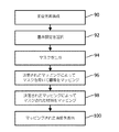
図6Aを参照すると、CTスペクトル画像の視覚化設定を調整する一実施例が、示される。60において、対象のスペクトル投影データ20が、検出器アレイ16から受信されることができ、パラメータ変更ユニット22が、サブ体積24によって異なる対応する撮像パラメータ、例えば変調されたエネルギを記録することができる。前記受信及び記録は、各サブ体積24に対して繰り返される。
Referring to FIG. 6A, an example of adjusting the visualization settings of the CT spectrum image is shown. At 60, the
62において、体積画像データ28及び材料特有画像が、前記スペクトル投影データから再構成ユニット26により再構成されることができ、タグ付けされたサブ体積30、例えば撮像パラメータ変更によってラベル付けされた体積画像を有する画像スライスを含むことができる。一実施例において、前記体積画像データ又はタグ付けされたサブ体積は、エネルギレベルにより合成される。
In 62, the volumetric image data 28 and the material-specific image can be reconstructed from the spectral projection data by the
基準設定34は、64において受信される。基準設定34の選択は、入力装置44から及び/又はユーザログイン若しくは医療関係者アイデンティティ、撮像プロトコル選択、及び患者情報等のようなCT撮像装置12に対する他の動作情報の一部として受信されることができる。
The reference setting 34 is received at 64. The selection of the reference setting 34 is received from the
66において、マスク38が、マッピングユニット32により前記再構成された材料特有画像に基づいて体積画像データ28、各タグ付けされたサブ体積30又は各MonoE画像データ31に対して生成される。前記マスクは、体積画像データ28に対する1つのマスクとして又は各タグ付けされたサブ体積30若しくはMonoE画像データ31に対する個別のマスクとして構成されることができる。各マスクは、調整された基準設定35に対して分析され、第1のマッピングにおいてグレイスケール値にマッピングされる体積画像データ28、サブ体積又はMonoE画像データHU値におけるボクセルを制限するバイナリマスクである。
In 66, a
68において、各タグ付けされたサブ体積又はMonoE画像データは、調整された基準設定35による対応する生成されたマスクを使用してマッピングされる。例えば、下肺野におけるスライス、例えば第1のサブ体積は、カルシウムなしのヨウ素マスクの第1のマスクを使用して調整された基準設定の第1のセットによってマッピングされる。上肺/心臓野におけるスライス、例えば第2のサブ体積は、カルシウムなしのヨウ素の第2のマスクを使用して調整された基準設定の第2のセットによってマッピングされる。各マッピングは、調整された基準設定35によるグレイスケール値に対するHUボクセル値の線形又は非線形変換を含む。 At 68, each tagged subvolume or MonoE image data is mapped using the corresponding generated mask according to the adjusted reference setting 35. For example, slices in the lower lung field, such as the first subvolume, are mapped by a first set of reference settings adjusted using a first mask of calcium-free iodine masks. Slices in the upper lung / cardiac field, such as the second subvolume, are mapped by a second set of baselines adjusted using a second mask of calcium-free iodine. Each mapping includes a linear or non-linear transformation of HU voxel values to grayscale values with adjusted reference setting 35.
70において、前記マスクされた材料は、前記サブ体積又はMonoE画像データに対して調整された選択された基準設定によってマッピングされる。例えば、下肺野スライスにおけるマスクされたボクセルのHU値は、前記調整された基準設定の第2のセットによって前記グレイスケール値にマッピングされる。前記第2のマッピングは、隣接したグレイスケール値にマッピングされる及び/又は前記第1のマッピングと重複することができる。前記第2のマッピングは、マスク構成による各サブ体積又はMonoE画像データに対して実行され、例えば各マスクは、調整された基準設定を使用して個別にマッピングされる。 At 70, the masked material is mapped by the selected reference setting adjusted to the sub-volume or MonoE image data. For example, the masked voxel HU value in the lower lung field slice is mapped to the grayscale value by the second set of the adjusted reference settings. The second mapping can be mapped to adjacent grayscale values and / or overlap with the first mapping. The second mapping is performed on each subvolume or MonoE image data according to the mask configuration, eg, each mask is individually mapped using adjusted reference settings.
1以上のマッピングされたサブ体積、マッピングされたMonoE画像データ及び/又は前記マッピングされた体積の部分は、72において表示装置36に表示される。前記マッピングされた体積の位置及び/又は向きは、入力装置44から受信されたコマンドにより決定されることができる。例えば、下肺野の第1のスライスが、前記表示装置に表示される。前記スライスは、マウススクロールを使用してステップごとに示されることができる。一部の例において、前記表示が、下肺野におけるスライスから上肺野に遷移すると、前記マッピングは、ピークエネルギのような撮像パラメータが変化したとしても、肺組織間で視覚的に一貫した状態に前記グレイスケール値を保つ。更に、前記造影剤により造影された組織は、画像スライス間で一貫しているように見える。他の例において、複数のスライスから得られた体積の部分を使用する正面像が、表示される。一部の例において、造影組織を含む組織は、異なる部分が、視野面に対するサブ体積の向きによって異なるマッピングを持ちうるとしても、前記正面像にわたり一貫しているように見える。他の例において、肺野のマッピングされた40keV画像が、表示され、異なる調整された基準設定で各々がマッピングされた同じ領域の120keV画像と比較される。
One or more mapped subvolumes, mapped MonoE image data and / or portions of said mapped volume are displayed on the
図6Bを参照すると、異なるエネルギ、異なる変調されたエネルギ、例えば取得中の撮像パラメータの変化における異なるサブ体積における2つの再構成体積画像データの間、又はMonoE画像の間のような、CT画像の視覚化設定を調整する一実施例が、示される。60において、対象のCT投影データ20は、検出器アレイ16から受信されることができ、パラメータ変更ユニット22は、サブ体積24によって異なる対応する撮像パラメータを記録することができる。前記順及び記録は、各サブ体積24に対して繰り返される。
With reference to FIG. 6B, of CT images, such as between two reconstructed volume image data in different subvolumes with different energies, different modulated energies, eg changes in imaging parameters during acquisition, or between MonoE images. An embodiment of adjusting the visualization settings is shown. At 60, the
82において、体積画像データ28は、再構成ユニット26により前記CT投影データから再構成されることができ、タグ付けされたサブ体積30、例えば撮像パラメータの変化によってラベル付けされた前記体積画像を有する画像スライス及び/又はMonoE画像データ、例えばエネルギレベルにより合成されたタグ付けされたサブ体積30を含むことができる。前記再構成は、再構成された体積画像データ28をMonoE画像データ31に合成することを含むことができる。一実施例において、前記再構成は、記憶部から以前に再構成された体積画像データを受信することを含む。
At 82, the volume image data 28 can be reconstructed from the CT projection data by the
基準設定34選択は、84において受信される。前記選択は、入力装置44から及び/又はユーザログイン若しくは医療関係者アイデンティティ、撮像プロトコル選択、及び患者情報等のような、CT撮像装置12に対する他の動作情報の一部として受信されることができる。
The reference setting 34 selection is received at 84. The selection can be received from the
86において、前記体積画像データ、各タグ付けされたサブ体積又はMonoE画像データは、画素値分布分析によって調整される前記選択された基準設定によってマッピングされる。例えば、下肺野におけるスライスは、調整された基準設定の第1のセットでマッピングされる。上肺/心臓野におけるスライスは、調整された基準設定の第2のセットでマッピングされる。各マッピングは、前記調整された基準設定によるグレイスケール値に対するボクセルHU値の線形又は非線形変換を含む。 At 86, the volume image data, each tagged subvolume or MonoE image data is mapped by the selected reference setting adjusted by pixel value distribution analysis. For example, slices in the lower lung field are mapped with a first set of adjusted reference settings. Slices in the upper lung / cardiac field are mapped in a second set of adjusted reference settings. Each mapping includes a linear or non-linear transformation of voxel HU values to grayscale values with the adjusted reference settings.
前記1以上のマッピングされたサブ体積、1以上のマッピングされたMonoE画像データ及び/又は前記マッピングされた体積の部分は、88において表示装置36に表示される。前記マッピングされた体積の位置及び/又は向きは、入力装置44から受信されたコマンドにより決定されることができる。
The one or more mapped subvolumes, the one or more mapped MonoE image data and / or the portion of the mapped volume is displayed on the
図6Cを参照すると、CTスペクトル画像の視覚化設定を調整する一実施例が、示される。90において、体積画像データ28及び材料特有画像は、再構成ユニット26により前記スペクトル投影データから再構成される。
Referring to FIG. 6C, an example of adjusting the visualization settings of the CT spectrum image is shown. At 90, the volumetric image data 28 and the material-specific image are reconstructed from the spectral projection data by the
基準設定34選択は、92において受信される。前記選択は、入力装置44から及び/又はユーザログイン若しくは医療関係者アイデンティティ、撮像プロトコル選択、及び患者情報等のようなCT撮像装置12に対する他の動作情報の一部として受信されることができる。
The reference setting 34 selection is received at 92. The selection can be received from the
94において、マスク38が、マッピングユニット32により前記再構成された材料特有画像に基づいて体積画像データ28に対して生成される。前記マスクは、第1のマッピングにおいて基準設定又は調整された基準設定を用いてグレイスケール値にマッピングされる体積画像データ28HU値におけるボクセルを制限する、バイナリマスクである。
At 94, a
96において、体積画像データ28は、前記生成されたマスクを使用して及び選択された基準設定の第1のセット又は調整された基準設定の第1のセットによってマッピングされる。例えば、腹部領域の体積は、水なしヨウ素マスクのマスクを使用してマッピングされる。前記マッピングは、前記基準設定又は調整された基準設定によって選択されたグレイスケール値に対するHU値の線形又は非線形変換を含む。 At 96, the volumetric image data 28 is mapped using the generated mask and by a first set of selected reference settings or a first set of adjusted reference settings. For example, the volume of the abdominal region is mapped using the mask of a waterless iodine mask. The mapping comprises a linear or non-linear transformation of the HU value to the grayscale value selected by the reference setting or the adjusted reference setting.
98において、前記マスクされた材料は、前記選択された基準設定又は調整された基準設定によってマッピングされる。例えば、前記腹部領域におけるマスクされたボクセルのHU値は、前記基準設定によって前記グレイスケール値にマッピングされる。前記第2のマッピングは、隣接したグレイスケール値にマッピングされる及び/又は前記第1のマッピングと重複することができる。 At 98, the masked material is mapped by the selected reference setting or the adjusted reference setting. For example, the HU value of the masked voxel in the abdominal region is mapped to the grayscale value by the reference setting. The second mapping can be mapped to adjacent grayscale values and / or overlap with the first mapping.
前記マッピングされた体積のビューは、100において表示装置36に表示される。前記マッピングされた体積のビューの位置及び/又は向きは、入力装置44から受信されたコマンドにより決定される及び/又は前記撮像プロトコルによるデフォルトであることができる。
The view of the mapped volume is displayed on the
図6A乃至6Cを参照する上記記載は、コンピュータプロセッサにより実行される場合に、前記プロセッサに上記の動作を実行させる、非一時的コンピュータ可読記憶媒体上で符号化された又は埋め込まれたコンピュータ可読命令を手段として実施されてもよい。加えて又は代わりに、前記コンピュータ可読命令の少なくとも1つは、信号、搬送波又は他の一時的媒体により搬送される。更に、前記ステップの順序は、変更されることができ、特定のステップは、省略されることができる。 The above description with reference to FIGS. 6A-6C is a computer-readable instruction encoded or embedded on a non-temporary computer-readable storage medium that, when executed by a computer processor, causes the processor to perform the above operation. It may be carried out by means. In addition or instead, at least one of the computer-readable instructions is carried by a signal, carrier wave or other temporary medium. Further, the order of the steps can be changed and certain steps can be omitted.
本発明は、好適な実施例を参照して記載されている。修正及び変更は、先行する詳細な記載を読み、理解すると他者が思いつきうる。本発明が、添付の請求項又は同等物の範囲内に入る限りこのような修正及び変更を全て含むと解釈されることが意図される。 The present invention has been described with reference to suitable examples. Amendments and changes can be conceived by others if they read and understand the preceding detailed description. It is intended that the present invention be construed as including all such modifications and modifications as long as it falls within the appended claims or equivalents.
Claims (15)
ハウンスフィールド単位(HU)値を持つ対象の再構成された体積画像データ、及び基準設定のセットを受信し、前記受信された再構成された体積画像データから前記基準設定に従い選択されたHU値の画素値分布分析によって、前記基準設定のセットを調整し、調整された基準設定のセットを得、前記調整された基準設定のセットによってHU値をグレースケール値にマッピングするマッピングユニット、
を有し、前記受信された基準設定のセットは、前記再構成された体積画像データのHU値からグレースケール画素値への、撮像プロトコルに従うマッピングを含み、前記調整された基準設定のセットは、前記選択されたHU値の画素値分布解析に従って調整された前記HU値のウィンドウレベル及び前記HU値のウィンドウ幅を含む、システム。 In a computed tomography (CT) image display system
Hounsfield units (HU) value target of the reconstructed volumetric image data with, and receives a set of standard setting, which is selected in accordance with the criteria set before Symbol received reconstructed volumetric image data HU the pixel value distribution analysis value, adjusting the set of the reference set, to obtain a set of adjusted reference set, mapping unit for mapping the HU value by a set of the adjusted reference set to gray over the scale value,
Have a said set of received reference set, the from HU value of the volume image data reconstructed to grayscale pixel values, comprising a mapping according to the imaging protocol, a set of the adjusted reference setting, A system comprising the window level of the HU value and the window width of the HU value adjusted according to the pixel value distribution analysis of the selected HU value .
画像サブ体積による撮像パラメータの少なくとも1つの変化を含む、複数の画像サブ体積、又は
それぞれ所定のエネルギレベルによる合成された画像データを含む、複数のMonoE画像データ、
の少なくとも1つを含み、
前記複数の画像サブ体積の各々又は前記複数のMonoE画像データの各々が、異なる調整された基準設定のセットを含む、請求項1に記載のシステム。 The reconstructed volume image data includes a plurality of image data, and the plurality of image data includes a plurality of image data.
Multiple MonoE image data, including a plurality of image sub-volumes, each containing a composite image data at a given energy level, including at least one change in imaging parameters with image sub-volume.
Including at least one of
The system of claim 1, wherein each of the plurality of image subvolumes or each of the plurality of MonoE image data comprises a different set of adjusted reference settings.
前記基準設定のセットが、第1のエネルギレベルにより、前記調整された基準設定のセットが、前記第1のエネルギレベルとは異なる第2のエネルギレベルによる、
請求項3乃至5のいずれか一項に記載のシステム。 The system includes a display device that displays a view of the received volumetric image data by a linear or non-linear transformation of the HU values selected by the adjusted set of reference settings.
The set of reference settings is due to a first energy level, and the adjusted set of reference settings is due to a second energy level that is different from the first energy level.
The system according to any one of claims 3 to 5.
を含む、請求項2に記載のシステム。 A parameter change unit that records at least one change in imaging parameters between subvolumes of projection data used to reconstruct said volumetric image data.
2. The system according to claim 2.
ハウンスフィールド単位(HU)値を持つ対象の再構成された体積画像データ、及び基準設定のセットを受信するステップと、
前記受信された再構成された体積画像データから前記基準設定に従い選択されたHU値の画素値分布分析によって、前記基準設定のセットを調整し、調整された基準設定のセットを得るステップと、
前記調整された基準設定のセットによって、ボクセルのHU値をグレースケール値にマッピングするステップと、
を有し、前記受信された基準設定のセットは、前記再構成された体積画像データのHU値からグレースケール画素値への、撮像プロトコルに従うマッピングを含み、前記調整された基準設定のセットは、前記選択されたHU値の画素値分布解析に従って調整された前記HU値のウィンドウレベル及び前記HU値のウィンドウ幅を含む、する方法。 In how to adjust computed tomography (CT) visualization settings
Receiving Hounsfield units (HU) in subjects with values reconstructed volumetric image data, a set of及beauty standards set,
The pixel value distribution analysis of selected HU value in accordance with said reference setting from the reconstructed volumetric image data has been received before reporting, the steps of adjusting the set of the reference set, obtain a set of adjusted reference set,
By a set of the adjusted reference set, and mapping the HU value of the voxel gray over the scale value,
Have a said set of received reference set, the from HU value of the volume image data reconstructed to grayscale pixel values, comprising a mapping according to the imaging protocol, a set of the adjusted reference setting, A method of including the window level of the HU value and the window width of the HU value adjusted according to the pixel value distribution analysis of the selected HU value.
画像サブ体積による撮像パラメータの少なくとも1つの変化を含む、複数の画像サブ体積、又は
それぞれ所定のエネルギレベルによる、合成された画像データを含む、複数のMonoE画像データ、
の少なくとも1つを含み、
前記複数の画像サブ体積の各々又は前記複数のMonoE画像データの各々が、異なる調整された基準設定のセットを含む、請求項9に記載の方法。 The reconstructed volume image data includes a plurality of image data, and the plurality of image data includes a plurality of image data.
Multiple MonoE image data, including a plurality of image subvolumes, each containing at least one change in imaging parameters with image subvolumes, or combined image data with a given energy level.
Including at least one of
9. The method of claim 9, wherein each of the plurality of image subvolumes or each of the plurality of MonoE image data comprises a different set of adjusted reference settings.
を含む、請求項10に記載の方法。 A step of recording at least one change in imaging parameters between image subvolumes of projection data used to reconstruct said volumetric image data.
10. The method of claim 10.
Applications Claiming Priority (3)
| Application Number | Priority Date | Filing Date | Title |
|---|---|---|---|
| US201562195975P | 2015-07-23 | 2015-07-23 | |
| US62/195,975 | 2015-07-23 | ||
| PCT/IB2016/053962 WO2017013514A1 (en) | 2015-07-23 | 2016-07-01 | Computed tomography visualization adjustment |
Publications (3)
| Publication Number | Publication Date |
|---|---|
| JP2018524110A JP2018524110A (en) | 2018-08-30 |
| JP2018524110A5 JP2018524110A5 (en) | 2019-08-08 |
| JP6835813B2 true JP6835813B2 (en) | 2021-02-24 |
Family
ID=56409659
Family Applications (1)
| Application Number | Title | Priority Date | Filing Date |
|---|---|---|---|
| JP2018501164A Active JP6835813B2 (en) | 2015-07-23 | 2016-07-01 | Computed tomography visualization adjustment |
Country Status (5)
| Country | Link |
|---|---|
| US (1) | US11257261B2 (en) |
| EP (1) | EP3324846B1 (en) |
| JP (1) | JP6835813B2 (en) |
| CN (1) | CN107847209A (en) |
| WO (1) | WO2017013514A1 (en) |
Families Citing this family (9)
| Publication number | Priority date | Publication date | Assignee | Title |
|---|---|---|---|---|
| US10977811B2 (en) * | 2017-12-20 | 2021-04-13 | AI Analysis, Inc. | Methods and systems that normalize images, generate quantitative enhancement maps, and generate synthetically enhanced images |
| EP3576048A1 (en) * | 2018-05-29 | 2019-12-04 | Koninklijke Philips N.V. | Adaptive window generation for multi-energy x-ray |
| EP3605448A1 (en) | 2018-08-01 | 2020-02-05 | Koninklijke Philips N.V. | Method for providing automatic adaptive energy setting for ct virtual monochromatic imaging |
| DE102019200269A1 (en) * | 2019-01-11 | 2020-07-16 | Siemens Healthcare Gmbh | Providing a restriction image data set and / or a difference image data set |
| DE102019200270A1 (en) | 2019-01-11 | 2020-07-16 | Siemens Healthcare Gmbh | Providing a difference image data set and providing a trained function |
| US11030742B2 (en) | 2019-03-29 | 2021-06-08 | GE Precision Healthcare LLC | Systems and methods to facilitate review of liver tumor cases |
| TWI714440B (en) * | 2020-01-20 | 2020-12-21 | 緯創資通股份有限公司 | Device and method for post-processing of computed tomography |
| CN111696164B (en) * | 2020-05-15 | 2023-08-25 | 平安科技(深圳)有限公司 | Self-adaptive window width and window level adjusting method, device, computer system and storage medium |
| EP4064178A1 (en) | 2021-03-23 | 2022-09-28 | Koninklijke Philips N.V. | Transfering a modality-specific image characterstic to a common reference image characteristic |
Family Cites Families (25)
| Publication number | Priority date | Publication date | Assignee | Title |
|---|---|---|---|---|
| US5305204A (en) | 1989-07-19 | 1994-04-19 | Kabushiki Kaisha Toshiba | Digital image display apparatus with automatic window level and window width adjustment |
| JP3188491B2 (en) | 1990-10-24 | 2001-07-16 | コーニンクレッカ フィリップス エレクトロニクス エヌ ヴィ | Dynamic compression method and apparatus for X-ray recording |
| US5900732A (en) | 1996-11-04 | 1999-05-04 | Mayo Foundation For Medical Education And Research | Automatic windowing method for MR images |
| AU2002341671A1 (en) * | 2001-09-14 | 2003-04-01 | Cornell Research Foundation, Inc. | System, method and apparatus for small pulmonary nodule computer aided diagnosis from computed tomography scans |
| US6990222B2 (en) | 2001-11-21 | 2006-01-24 | Arnold Ben A | Calibration of tissue densities in computerized tomography |
| DE10229113A1 (en) | 2002-06-28 | 2004-01-22 | Siemens Ag | Process for gray value-based image filtering in computer tomography |
| US6898263B2 (en) | 2002-11-27 | 2005-05-24 | Ge Medical Systems Global Technology Company, Llc | Method and apparatus for soft-tissue volume visualization |
| US7218763B2 (en) | 2003-02-27 | 2007-05-15 | Eastman Kodak Company | Method for automated window-level settings for magnetic resonance images |
| US7865022B2 (en) * | 2005-08-31 | 2011-01-04 | Canon Kabushiki Kaisha | Information processing apparatus, image processing apparatus, control method, and computer readable storage medium |
| WO2008104897A1 (en) | 2007-03-01 | 2008-09-04 | Koninklijke Philips Electronics, N.V. | Image viewing window |
| US9064300B2 (en) * | 2008-02-15 | 2015-06-23 | Siemens Aktiengesellshaft | Method and system for automatic determination of coronory supply regions |
| JP2011514822A (en) | 2008-03-03 | 2011-05-12 | エージェンシー フォー サイエンス,テクノロジー アンド リサーチ | Method and system for segmenting CT scan data |
| US8049924B2 (en) * | 2008-05-27 | 2011-11-01 | Xerox Corporation | Methods and apparatus for color control of coated images on a printed media |
| US20100130860A1 (en) * | 2008-11-21 | 2010-05-27 | Kabushiki Kaisha Toshiba | Medical image-processing device, medical image-processing method, medical image-processing system, and medical image-acquiring device |
| US8115784B2 (en) * | 2008-11-26 | 2012-02-14 | General Electric Company | Systems and methods for displaying multi-energy data |
| EP2591456B1 (en) * | 2010-07-10 | 2018-11-28 | Université Laval | Image intensity standardization |
| JP5764976B2 (en) * | 2011-03-03 | 2015-08-19 | セイコーエプソン株式会社 | Dot formation position adjusting apparatus, recording method, setting method, and recording program |
| US8751961B2 (en) * | 2012-01-30 | 2014-06-10 | Kabushiki Kaisha Toshiba | Selection of presets for the visualization of image data sets |
| US9349199B2 (en) * | 2012-06-26 | 2016-05-24 | General Electric Company | System and method for generating image window view settings |
| US9076033B1 (en) * | 2012-09-28 | 2015-07-07 | Google Inc. | Hand-triggered head-mounted photography |
| US9008274B2 (en) * | 2012-12-24 | 2015-04-14 | General Electric Company | Systems and methods for selecting image display parameters |
| US9536423B2 (en) * | 2013-03-31 | 2017-01-03 | Case Western Reserve University | Fiber optic telemetry for switched-mode current-source amplifier in magnetic resonance imaging (MRI) |
| BR112015026040A2 (en) | 2013-04-18 | 2017-07-25 | Koninklijke Philips Nv | medical image mapping method, medical image mapping system, and, computer program product |
| WO2014201052A2 (en) * | 2013-06-10 | 2014-12-18 | University Of Mississippi Medical Center | Medical image processing method |
| CN106102583A (en) * | 2014-01-10 | 2016-11-09 | 泰勒顿国际公司 | Cicatrix and the detection of fiber heart area |
-
2016
- 2016-07-01 CN CN201680043192.1A patent/CN107847209A/en active Pending
- 2016-07-01 WO PCT/IB2016/053962 patent/WO2017013514A1/en unknown
- 2016-07-01 EP EP16738556.6A patent/EP3324846B1/en active Active
- 2016-07-01 JP JP2018501164A patent/JP6835813B2/en active Active
- 2016-07-01 US US15/745,158 patent/US11257261B2/en active Active
Also Published As
| Publication number | Publication date |
|---|---|
| US11257261B2 (en) | 2022-02-22 |
| CN107847209A (en) | 2018-03-27 |
| EP3324846A1 (en) | 2018-05-30 |
| WO2017013514A1 (en) | 2017-01-26 |
| JP2018524110A (en) | 2018-08-30 |
| US20190012815A1 (en) | 2019-01-10 |
| EP3324846B1 (en) | 2021-05-12 |
Similar Documents
| Publication | Publication Date | Title |
|---|---|---|
| JP6835813B2 (en) | Computed tomography visualization adjustment | |
| US10147168B2 (en) | Spectral CT | |
| Dougherty | Digital image processing for medical applications | |
| Seeram et al. | Digital radiography | |
| US8644595B2 (en) | Methods and apparatus for displaying images | |
| US7860331B2 (en) | Purpose-driven enhancement filtering of anatomical data | |
| JP7194143B2 (en) | Systems and methods to facilitate review of liver tumor cases | |
| US10867375B2 (en) | Forecasting images for image processing | |
| Wang et al. | Low‐dose preview for patient‐specific, task‐specific technique selection in cone‐beam CT | |
| CN105962959A (en) | Creating a resultant image for a specifiable, virtual X-ray quanta energy distribution | |
| KR101971625B1 (en) | Apparatus and method for processing CT image | |
| JP7084120B2 (en) | Medical image processing equipment, medical image processing methods, and medical image processing programs | |
| Yoon et al. | Digital radiographic image processing and analysis | |
| KR20150095140A (en) | Computer tomography apparatus and method for reconstructing a computer tomography image thereof | |
| CN108601570B (en) | Tomographic image processing apparatus and method, and recording medium relating to the method | |
| KR20160061248A (en) | Apparatus for processing medical image and method for processing medical image thereof | |
| Chawla et al. | Dual-energy CT applications in salivary gland lesions | |
| US7457816B2 (en) | Method for depicting an object displayed in a volume data set | |
| US20170236324A1 (en) | Unified 3D volume rendering and maximum intensity projection viewing based on physically based rendering | |
| Sprawls | Optimizing medical image contrast, detail and noise in the digital era | |
| US7116808B2 (en) | Method for producing an image sequence from volume datasets | |
| KR20180054020A (en) | Apparatus and method for processing medical image, and computer readable recording medium related to the method | |
| CN115428025A (en) | Apparatus for generating an enhanced image of an object | |
| Chae et al. | Lung segmentation using prediction-based segmentation improvement for chest tomosynthesis | |
| Jadidi et al. | Dependency of image quality on acquisition protocol and image processing in chest tomosynthesis—a visual grading study based on clinical data |
Legal Events
| Date | Code | Title | Description |
|---|---|---|---|
| A521 | Request for written amendment filed |
Free format text: JAPANESE INTERMEDIATE CODE: A523 Effective date: 20190627 |
|
| A621 | Written request for application examination |
Free format text: JAPANESE INTERMEDIATE CODE: A621 Effective date: 20190627 |
|
| A977 | Report on retrieval |
Free format text: JAPANESE INTERMEDIATE CODE: A971007 Effective date: 20200330 |
|
| A131 | Notification of reasons for refusal |
Free format text: JAPANESE INTERMEDIATE CODE: A131 Effective date: 20200428 |
|
| A601 | Written request for extension of time |
Free format text: JAPANESE INTERMEDIATE CODE: A601 Effective date: 20200722 |
|
| A521 | Request for written amendment filed |
Free format text: JAPANESE INTERMEDIATE CODE: A523 Effective date: 20201028 |
|
| TRDD | Decision of grant or rejection written | ||
| A01 | Written decision to grant a patent or to grant a registration (utility model) |
Free format text: JAPANESE INTERMEDIATE CODE: A01 Effective date: 20210107 |
|
| A61 | First payment of annual fees (during grant procedure) |
Free format text: JAPANESE INTERMEDIATE CODE: A61 Effective date: 20210204 |
|
| R150 | Certificate of patent or registration of utility model |
Ref document number: 6835813 Country of ref document: JP Free format text: JAPANESE INTERMEDIATE CODE: R150 |
|
| R250 | Receipt of annual fees |
Free format text: JAPANESE INTERMEDIATE CODE: R250 |