JP6833478B2 - Ventilation system for closed equipment - Google Patents
Ventilation system for closed equipment Download PDFInfo
- Publication number
- JP6833478B2 JP6833478B2 JP2016228470A JP2016228470A JP6833478B2 JP 6833478 B2 JP6833478 B2 JP 6833478B2 JP 2016228470 A JP2016228470 A JP 2016228470A JP 2016228470 A JP2016228470 A JP 2016228470A JP 6833478 B2 JP6833478 B2 JP 6833478B2
- Authority
- JP
- Japan
- Prior art keywords
- side wall
- ventilation
- top plate
- opening edge
- bottom plate
- Prior art date
- Legal status (The legal status is an assumption and is not a legal conclusion. Google has not performed a legal analysis and makes no representation as to the accuracy of the status listed.)
- Active
Links
- 238000009423 ventilation Methods 0.000 title claims description 116
- 238000009413 insulation Methods 0.000 claims description 6
- 238000005192 partition Methods 0.000 claims description 4
- 238000009434 installation Methods 0.000 description 8
- 230000000694 effects Effects 0.000 description 7
- XLYOFNOQVPJJNP-UHFFFAOYSA-N water Substances O XLYOFNOQVPJJNP-UHFFFAOYSA-N 0.000 description 6
- 239000000428 dust Substances 0.000 description 4
- 239000002184 metal Substances 0.000 description 3
- 239000000126 substance Substances 0.000 description 2
- 241000238631 Hexapoda Species 0.000 description 1
- 241001465754 Metazoa Species 0.000 description 1
- 241000699670 Mus sp. Species 0.000 description 1
- 238000004140 cleaning Methods 0.000 description 1
- 239000000470 constituent Substances 0.000 description 1
- 238000001816 cooling Methods 0.000 description 1
- 230000007613 environmental effect Effects 0.000 description 1
- 238000007689 inspection Methods 0.000 description 1
- 238000004519 manufacturing process Methods 0.000 description 1
- 239000000463 material Substances 0.000 description 1
- 238000000465 moulding Methods 0.000 description 1
- 230000002093 peripheral effect Effects 0.000 description 1
- 238000003466 welding Methods 0.000 description 1
Images


Landscapes
- Cooling Or The Like Of Electrical Apparatus (AREA)
- Patch Boards (AREA)
Description
本発明は金属閉鎖形スイッチギヤや金属閉鎖形配電盤等に係る閉鎖形機器の換気装置に関する。 The present invention relates to a ventilation device for a closed device such as a metal closed switch gear or a metal closed switchboard.
従来のスイッチギヤ等の閉鎖形機器は、内部の温度上昇を抑えるために、扉や天井部に換気口が設けられ、自然対流または強制対流による換気装置により冷却されている。発熱量の大きいトランスや大電流定格の遮断器を収納したスイッチギヤ等は、効率よく冷却するために、換気面積を多くとれる換気筒や換気扇を収納した換気装置を天井部上方に突出して設置されていた(例えば特許文献1参照)。 Conventional closed-type devices such as switch gears are provided with ventilation openings on the doors and ceilings in order to suppress an internal temperature rise, and are cooled by a ventilation device by natural convection or forced convection. For efficient cooling of transformers that generate a large amount of heat and switch gears that house circuit breakers with a large current rating, a ventilation tube that can take a large ventilation area and a ventilation device that houses a ventilation fan are installed so as to project above the ceiling. (See, for example, Patent Document 1).
従来の閉鎖形機器の換気装置を天井部上に設置すると、閉鎖形機器の全高がその換気装置の高さ寸法分高くなり、輸送トラックの高さ制限から、換気装置を取外して出荷せねばならない場合があり、その際は、換気装置を別送したり現地で取付けたりする費用が余分にかかる問題があった。また、工場内や現地据付等で、クレーンで配電盤を吊る作業の際、ワイヤーが換気装置に干渉し、取外しを必要とする場合も生じ、前記と同様の問題が発生する。
例えば、強制対流を必要としない場合で、換気筒等の換気装置を天井部に設置せず、単純に天井部に直接換気口を設けてやれば、閉鎖形機器の高さ寸法は高くならない。しかし、異物や水滴の垂直方向の侵入を防止するため、換気口部にフィルタを取り付けたり、簡易屋根等を設置したりする必要がある。どちらも換気面積が小さくなるというデメリットに加え、前者の場合は、フィルタの費用が高くなることとフィルタの目詰まりを防ぐため、こまめな点検が必要となる。後者の場合は、簡易屋根等の組立・取付費用が追加されることと、換気筒と同様に取外しが必要な場合があるという問題があった。
When the ventilation device of the conventional closed equipment is installed on the ceiling, the total height of the closed equipment is increased by the height dimension of the ventilation device, and the ventilation device must be removed and shipped due to the height limitation of the transportation truck. In some cases, there was a problem that the cost of separately sending the ventilation system or installing it on site was extra. In addition, when the switchboard is hung by a crane in a factory or on-site installation, the wire may interfere with the ventilation device and need to be removed, which causes the same problem as described above.
For example, when forced convection is not required, if a ventilation device such as a ventilation cylinder is not installed on the ceiling and a ventilation port is simply provided on the ceiling, the height dimension of the closed device will not increase. However, in order to prevent foreign matter and water droplets from entering in the vertical direction, it is necessary to attach a filter to the ventilation port or install a simple roof or the like. In addition to the demerit that the ventilation area is small in both cases, in the former case, frequent inspection is required in order to increase the cost of the filter and prevent clogging of the filter. In the latter case, there are problems that the cost of assembling and installing a simple roof and the like is added, and that it may be necessary to remove the ventilation cylinder as well.
この発明は前記のような課題を解決するためになされたものであり、換気装置を含めた閉鎖形機器の全高が抑えられ、輸送時の取外しや、据付時の組立作業を不要にした安価にできる閉鎖形機器の換気装置を提供することを目的としている。 The present invention has been made to solve the above-mentioned problems, and the total height of the closed type equipment including the ventilation device is suppressed, and the removal at the time of transportation and the assembly work at the time of installation are not required at low cost. It is intended to provide a ventilator for closed equipment that can.
本発明に係る閉鎖形機器の換気装置は、閉鎖形機器の外殻を形成する筐体の天板を貫通するように形成された開口縁部と、底板部及びその底板部の周囲を上方向に伸ばした側壁部を有して形成され、前記側壁部の上端部周囲が前記開口縁部に沿って接続されて前記天板に凹部を形成し、その凹部の前記側壁部にそれぞれ複数の通風口を設けた通風部材と、を備え、前記通風部材は、前記筐体の内部に配置された内部構成機器および絶縁距離を隔てて上部から天板迄の空間に形成される。
The ventilation device of the closed type device according to the present invention has an opening edge formed so as to penetrate the top plate of the housing forming the outer shell of the closed type device, and the bottom plate portion and the periphery of the bottom plate portion upward. to be formed with a side wall portion extended, the upper end periphery of the side wall portion is the connected along the opening edge forming a recess in the top plate, each number multiple in the side wall of the recess A ventilation member provided with a ventilation port is provided, and the ventilation member is formed in a space from the upper portion to the top plate with an insulation distance and an internal component device arranged inside the housing.
本発明においては、前記構成としたことにより、閉鎖形機器の外殻を形成する筐体の高さが換気装置の高さ相当分増大するのを抑えることができ、輸送時の取外しや、据付時の組立作業を不要にした、安価な閉鎖形機器を得ることができる。 In the present invention, by adopting the above configuration, it is possible to suppress an increase in the height of the housing forming the outer shell of the closed device by the height corresponding to the height of the ventilation device, and it is possible to remove and install the device during transportation. It is possible to obtain an inexpensive closed-type device that eliminates the need for assembly work.
なお、本書においては閉鎖形機器がスイッチギヤである場合について説明する。
実施の形態1.
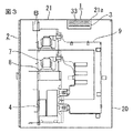
図1は本発明の実施の形態1における換気装置を設置したスイッチギヤを示す斜視図、図2は図1に示されたスイッチギヤがフィーダ2段積盤である場合の要部構成を示す縦断面図、図3は図1に示されたスイッチギヤが母線連絡盤である場合の要部構成を示す縦断面図、図4は図1から図3に示された換気装置の断面図(断面端面図)である。図において、実施の形態1の閉鎖形機器における換気装置1は、外形が密閉箱状に形成された金属閉鎖形のスイッチギヤ2を構成する筐体20の天板21を上下方向に貫通する如く形成された開口縁部21aと、水平方向に配設される底板部31及びその底板部31の周囲を上方向に伸ばすように形成された側壁部32を有する上面が開口された箱状に形成され、側壁部32の上端部周囲が前述の開口縁部21aに沿って接続されて天板21に凹部Aを形成し、その凹部Aの側壁部32に複数の通風口33を設けた通風部材3と、を備えるように構成されている。
In this document, the case where the closed type device is a switch gear will be described.
FIG. 1 is a perspective view showing a switch gear in which a ventilation device is installed according to the first embodiment of the present invention, and FIG. 2 is a vertical section showing a main configuration when the switch gear shown in FIG. 1 is a feeder two-stage stacking board. A top view, FIG. 3 is a vertical sectional view showing a main configuration when the switch gear shown in FIG. 1 is a bus connecting board, and FIG. 4 is a sectional view (cross section) of the ventilation device shown in FIGS. 1 to 3. End view). In the figure, the
なお、開口縁部21aを含む天板21と通風部材3とは、例えばプレス成形によって1枚の板材から一体に形成しても良いし、別部材として構成し、通風部材3を天板21の開口縁部21aに例えば溶接、ネジ止めなど適宜の固定手段によって取り付けるようにしても良い。また、開口縁部21aと通風部材3によって形成される凹部Aは、平面視四角形に限定されるものではなく、例えば他の多角形や円形状、あるいは多角形に円形などの曲線を組合わせた形状でも差し支えない。また、スイッチギヤ2は屋内に設置されるタイプとして構成されている。
The
換気装置1は、スイッチギヤ2の内部構成機器の配置や必要とする絶縁距離の寸法、ケーブルの端末処理寸法、据付先の作業スペース確保等の制約を満足した筐体20の内部空間で、制約を受けないスペース、すなわちデッドスペースの部分に配置される。例えば、図2は一般的なフィーダ2段積盤からなるスイッチギヤの天井部分における天板21に本発明の換気装置1を設置したものである。このスイッチギヤの場合、必要高さ寸法は、段積された2台の遮断器4や内部構成機器の配置、外線ケーブル5の必要端末処理寸法等によって決定されるが、例えば外線ケーブル5の必要寸法が不足する場合にはそれを確保するために、寸法が不足する分だけスイッチギヤ2を高くする必要がある。
The
このとき、スイッチギヤの全高を一様に高くするのではなく、ケーブル引出部の端末処理寸法相当分だけ当該箇所を部分的に高くした筐体とすることも可能ではあるが、筐体の共用化や作り易さ、別送の手間等で一般的には、スイッチギヤの筐体は直方体で構成される。そのため、遮断器4の上段回路に配置されている計器用変流器6の上部から天井迄がデッドスペースとなる。
また、図3は一般的な母線連絡盤からなるスイッチギヤの天板21に本発明の換気装置1を設置したものである。このスイッチギヤの場合、筐体20の必要高さ寸法は、母線連絡用の遮断器4と計器用変圧器7を収納した補助台車8が2台、内部構成機器の配置および列盤のため制御線を渡すための制御線用スペースBにより決定されているが、遮断器4と補助台車8、及び制御線用スペースBの高さから、上段側の補助台車8より配線される高圧電線9の必要絶縁距離寸法を除く上部の空間部分がデッドスペースとなっている。
At this time, instead of uniformly increasing the total height of the switch gear, it is possible to make the housing partially raised by the amount equivalent to the terminal processing dimension of the cable lead-out portion, but the housing is shared. Generally, the housing of the switch gear is composed of a rectangular parallelepiped because of its ease of use, ease of manufacture, and labor of separate delivery. Therefore, a dead space is formed from the upper part to the ceiling of the
Further, FIG. 3 shows a
なお、実施の形態1の換気装置1は前記のようにスイッチギヤ2の天井部における前述のデッドスペースに対応する部分の天板21に、図1〜図4のような開口縁部21aを設け、スイッチギヤ内部に向かって、箱状の凹部Aを形成する通風部材3を設けるが、その凹部Aの底面を形成している底板部31には通風口を設けず、凹部Aの周囲4面を構成する側壁部32にそれぞれ複数の通風口33を設ける。通風口33からは、底板部31の上面に溜まった塵埃類等が筐体20の内部に進入する虞もあるので、最も下側の通風口33の下端と底板部31の上面との寸法C(図4に図示)は、0<Cとすることが望ましい。
In the
また、通風口33の大きさ(面積)は特に限定されるものではない。例えば、小孔を網目状に多数設けたものでも良いし、その小孔よりも通風抵抗を小さくした大きめの穴を少数設けても良い。なお、通風口33から、例えばネズミなどの小動物や虫などの異物進入の可能性がある場合は、通風口33に異物進入防止用の金網等を設置しても良い。また、通風口33の設置個数または合計面積は設計上想定される最も厳しい条件下においても、スイッチギヤ2の構成機器を何れも許容温度以下に保持できる程度の内部温度上昇に抑えられる換気面積となるように設定される。なお、筐体20の底面や側壁部下部の空気取入れ口の構成、通風ファンの設置有無などは特に限定されるものではない。また、換気装置1は一つの筐体20に複数設置しても良い。
Further, the size (area) of the
前記のように構成された実施の形態1においては、スイッチギヤ2の筐体20内で温度上昇した空気は自然対流、または通風ファンを有する場合には強制対流作用によって筐体20内の天井部に移動し、換気装置1の側壁部32に設けられた複数の通風口33から天板21上の凹部Aを経て筐体20の外部に排出される。スイッチギヤ2の天板21上には外気中に浮遊する塵埃が落下したりして溜る一方、設置個所や清掃作業等の環境条件にもよるが、室内であっても水滴が降りかかる場合があるため、底板部31には通風口を設けていない。そのため、その底板部31によってそれら塵埃や水滴の筐体20内部への進入は防止され、筐体20の内部は保護される。なお、底板部31の上面や通風口33は定期的にメンテナンスされる。
In the first embodiment configured as described above, the air whose temperature has risen in the
前記のように実施の形態1によれば、換気装置1は、筐体20の天板21を貫通するように形成された開口縁部21aと、底板部31及びその底板部31の周囲を上方向に伸ばすように形成された側壁部32を有する箱状に形成され、側壁部32の上端部周囲が開口縁部21aに沿って接続されて天板21に凹部Aを形成し、その凹部を形成している側壁部32に複数の通風口33を設けた通風部材3とを用いて構成したので、換気装置の高さ分スイッチギヤ2の筐体20が高くなるのを抑えることができ、輸送や、据付時の組立を容易にすると共に、安価な閉鎖形機器を得ることができる。また、換気装置1の設置箇所を、筐体20の天板21の下部で内部機器の取付がなく、また、絶縁距離や外線端末寸法などの制約を受けないデッドスペースの部分としたので、筐体20の内部空間が有効に活用される。
As described above, according to the first embodiment, the
また、換気装置を天板21の上部に突設した場合と比べ、出荷のために換気装置を別送したり、据付現場で取付作業したりする手間や費用が不要となる。また、工場内や現地据付等のクレーン作業で、スイッチギヤと換気装置を取外すことなく、一体で吊ることができるので、作業時間が軽減される。さらに、強制対流を必要としない場合で、換気筒等の換気装置を天井部に設置せず、単純に天井部に直接換気口を設けたスイッチギヤと比較しても、垂直方向の異物や水滴の侵入を防止するために、換気口部にフィルタを取付けたり、簡易屋根等を設置したりする必要がなく、フィルタの交換作業や簡易屋根の費用も不要で、安価である。また、図4に示すように換気装置1は、天板の上部に設置する従来の換気装置と比べて、上部に換気口が飛び出していないため、横方向に異物が侵入し難い。
Further, as compared with the case where the ventilation device is projected above the
実施の形態2.
図5は本発明の実施の形態2における換気装置の要部を示す断面図である。図において、換気装置1の通風口33はランス加工やルーバー加工等が施された異物の進入を抑制するルーバー状の切り起こし32aによって形成されている。なお、換気装置1としての換気面積や天井部のデッドスペースに配置される点などその他の構成は実施の形態1と同様であるので説明を省略する。
前記のように構成された実施の形態2においては、前記実施の形態1と同様の効果に加えて、通風口33のランス加工やルーバー加工された箇所が水滴や異物が侵入し難い構造であり、異物侵入経路の障害となるため、スイッチギヤの内部構成機器の障害発生が抑制され信頼性が向上する効果が得られる。
FIG. 5 is a cross-sectional view showing a main part of the ventilation device according to the second embodiment of the present invention. In the figure, the
In the second embodiment configured as described above, in addition to the same effect as that of the first embodiment, the lance-processed and louver-processed portions of the
実施の形態3.
図6は本発明の実施の形態3における換気装置の要部を示す断面図、図7は図6に示された換気装置を示す上面図である。図において、通風部材3の底板部31の面積は、天板21の開口縁部21aによって形成される開口面積よりも大きく形成され、周囲4面の側壁部32は何れも上方向に向けて凹部Aの内側に傾斜した等脚台形状となっており、その傾斜された側壁部32に通風口33が設けられている。その他の構成は実施の形態1と同様であるので説明を省略する。
FIG. 6 is a cross-sectional view showing a main part of the ventilation device according to the third embodiment of the present invention, and FIG. 7 is a top view showing the ventilation device shown in FIG. In the figure, the area of the
前記のように構成された実施の形態3においては、天板21の開口縁部21aの開口面積及び凹部Aの深さが実施の形態1と同等の場合でも、通風部材3の底板部31の面積を開口縁部21aの開口面積よりも大きくして、側壁部32の形成面を等脚台形の形状としたことにより、その側壁部32の面積が図7のように増大され、その分、通風口33を多く設けることができる。このため、換気性能を向上させることができる。また、例えば、スイッチギヤのデッドスペースの高さ方向の寸法が小さい場合であっても、換気装置1の高さを低くすることができるので、必要な換気面積を確保できるという効果がある。また、実施の形態1と比べ、天板21の開口縁部21aの開口面積が同じ場合、異物混入のルートが長くなるため、室内の埃や水滴などが入り難い構造とすることができるという付随効果も得られる。
In the third embodiment configured as described above, even when the opening area of the opening
実施の形態4.
図8は本発明の実施の形態4における換気装置の要部を示す断面図である。図において、通風部材3の底板部31は中央部に向かって凹ませるような傾斜構造に形成され、中央部に凹所31aが設けられている。その他の構成は実施の形態1と同様であるので説明を省略する。
前記のように構成された実施の形態4においては、実施の形態1の効果に加え、底板部31の中央部に設けられた凹所31aに異物が溜り、通風口33への異物の侵入を抑制することができるという効果が得られる。
FIG. 8 is a cross-sectional view showing a main part of the ventilation device according to the fourth embodiment of the present invention. In the figure, the
In the fourth embodiment configured as described above, in addition to the effect of the first embodiment, foreign matter accumulates in the
実施の形態5.
図9は本発明の実施の形態5における換気装置の要部を示す図であり、(a)は斜視図、(b)は上面図である。図において、天板21に形成された四角形の箱状の凹部Aは、その対角線を結ぶように設けられた2枚の仕切板34で周方向に仕切られ、この例では凹部Aを四つの区画A1、A2、A3及びA4に区分されている。なお、凹部Aを区分する場合の区画数や仕切板34の形状などは特に限定されるものではない。また、例えば、開口縁部21aの形状が3角形や5角形以上の多角形の場合は各頂点や中心点を結ぶ線などから適宜に選び、また、円形の場合は、例えばその中心を通り、円を等角度に区分する線で均等になるように仕切られる。その他の構成は実施の形態1と同様であるので説明を省略する。
9A and 9B are views showing a main part of the ventilation device according to the fifth embodiment of the present invention, where FIG. 9A is a perspective view and FIG. 9B is a top view. In the figure, the quadrangular box-shaped recess A formed in the
前記のように構成された実施の形態5においては、実施の形態1の作用効果に加え、例えば、区画A1に存在する異物(図示省略)に区画A2の方向へ移動させる力が働いた場合、仕切板34により進路が塞がれるので、区画A2の通風口33にその異物が侵入するのを防ぐことができる。
In the fifth embodiment configured as described above, in addition to the action and effect of the first embodiment, for example, when a force acting in the direction of the compartment A2 acts on a foreign substance (not shown) existing in the compartment A1. Since the path is blocked by the
なお、本発明は、その発明の範囲内において、各実施の形態の一部または全部を自由に組み合わせたり、各実施の形態を適宜、変形、省略することが可能である。天板21の開口縁部21aの形状は正方形又は、長方形又は、円形又は、多角形に形成される構成とすることができる。
In the present invention, a part or all of each embodiment can be freely combined, and each embodiment can be appropriately modified or omitted within the scope of the invention. The shape of the opening
1 換気装置、2 スイッチギヤ、3 通風部材、4 遮断器、5 外線ケーブル、
6 計器用変流器、7 計器用変圧器、8 補助台車、9 高圧電線、20 筐体、
21 天板、21a 開口縁部、31 底板部、31a 凹所、32 側壁部、
32a 切り起こし、33 通風口、34 仕切板、A 凹部、
A1、A2、A3、A4 区画、B 制御線用スペース、C 寸法。
1 Ventilator, 2 Switch gear, 3 Ventilation member, 4 Circuit breaker, 5 External cable,
6 Instrument transformer, 7 Instrument transformer, 8 Auxiliary trolley, 9 High-voltage power line, 20 housing,
21 top plate, 21a opening edge, 31 bottom plate, 31a recess, 32 side wall,
32a cut up, 33 vents, 34 dividers, A recesses,
A1, A2, A3, A4 compartment, B control line space, C dimension.
Claims (7)
前記通風部材は、前記筐体の内部に配置された内部構成機器および絶縁距離を隔てて上部から前記天板迄の空間に形成されることを特徴とする閉鎖形機器の換気装置。 It is formed by having an opening edge portion formed so as to penetrate the top plate of the housing forming the outer shell of the closed type device, and a side wall portion extending upward around the bottom plate portion and the bottom plate portion. wherein is connected to the upper end periphery of the side wall portion along the opening edge portion forming a recess in the top plate includes a ventilation member respectively provided with vent holes of several in the side wall of the recess, and
The ventilation member is a ventilation device for a closed type device, which is formed in a space from an upper portion to the top plate with an insulation distance separated from an internal component device arranged inside the housing.
前記通風口は異物の進入を抑制するルーバー状の切り起こしによって形成されていることを特徴とする閉鎖形機器の換気装置。 It is formed by having an opening edge portion formed so as to penetrate the top plate of the housing forming the outer shell of the closed type device, and a side wall portion extending upward around the bottom plate portion and the bottom plate portion. A ventilation member is provided, wherein the periphery of the upper end portion of the side wall portion is connected along the opening edge portion to form a recess in the top plate, and a plurality of ventilation ports are provided in the side wall portion of the recess.
The vent ventilation system closed chain EQUIPMENT you characterized in that it is formed by a raised louvered cut inhibit the ingress of foreign matter.
前記底板部の面積を、前記開口縁部によって形成される開口面積よりも大きくしたことを特徴とする閉鎖形機器の換気装置。 It is formed by having an opening edge portion formed so as to penetrate the top plate of the housing forming the outer shell of the closed type device, and a side wall portion extending upward around the bottom plate portion and the bottom plate portion. A ventilation member is provided, wherein the periphery of the upper end portion of the side wall portion is connected along the opening edge portion to form a recess in the top plate, and a plurality of ventilation ports are provided in the side wall portion of the recess.
Wherein the area of the bottom plate portion, the ventilator closed chain EQUIPMENT you characterized by being larger than the opening area formed by the opening edge.
前記底板部の中央部は、該底板部の周囲部よりも低く凹ませてなることを特徴とする閉鎖形機器の換気装置。 It is formed by having an opening edge portion formed so as to penetrate the top plate of the housing forming the outer shell of the closed type device, and a side wall portion extending upward around the bottom plate portion and the bottom plate portion. A ventilation member is provided, wherein the periphery of the upper end portion of the side wall portion is connected along the opening edge portion to form a recess in the top plate, and a plurality of ventilation ports are provided in the side wall portion of the recess.
The central portion of the bottom plate portion, the ventilator closed chain EQUIPMENT you characterized by comprising Mase concave rather lower than the surrounding portion of the bottom plate portion.
前記天板の開口縁部と前記通風部材によって形成された前記凹部は、仕切板によって周方向に複数の区画に区分されていることを特徴とする閉鎖形機器の換気装置。 It is formed by having an opening edge portion formed so as to penetrate the top plate of the housing forming the outer shell of the closed type device, and a side wall portion extending upward around the bottom plate portion and the bottom plate portion. A ventilation member is provided, wherein the periphery of the upper end portion of the side wall portion is connected along the opening edge portion to form a recess in the top plate, and a plurality of ventilation ports are provided in the side wall portion of the recess.
Said recess said formed by the ventilation member and the opening edge portion of the top plate, ventilator closed chain EQUIPMENT you characterized in that it is divided into a plurality of compartments in the circumferential direction by a partition plate.
前記天板の開口縁部の形状は正方形又は、長方形又は、円形又は、多角形に形成されていることを特徴とする閉鎖形機器の換気装置。 It is formed by having an opening edge portion formed so as to penetrate the top plate of the housing forming the outer shell of the closed type device, and a side wall portion extending upward around the bottom plate portion and the bottom plate portion. A ventilation member is provided, wherein the periphery of the upper end portion of the side wall portion is connected along the opening edge portion to form a recess in the top plate, and a plurality of ventilation ports are provided in the side wall portion of the recess.
Wherein the shape of the opening edge portion of the top plate is square or rectangular or circular or be formed in a polygonal ventilator closed chain EQUIPMENT you characterized.
Priority Applications (1)
| Application Number | Priority Date | Filing Date | Title |
|---|---|---|---|
| JP2016228470A JP6833478B2 (en) | 2016-11-25 | 2016-11-25 | Ventilation system for closed equipment |
Applications Claiming Priority (1)
| Application Number | Priority Date | Filing Date | Title |
|---|---|---|---|
| JP2016228470A JP6833478B2 (en) | 2016-11-25 | 2016-11-25 | Ventilation system for closed equipment |
Publications (3)
| Publication Number | Publication Date |
|---|---|
| JP2018085869A JP2018085869A (en) | 2018-05-31 |
| JP2018085869A5 JP2018085869A5 (en) | 2019-09-05 |
| JP6833478B2 true JP6833478B2 (en) | 2021-02-24 |
Family
ID=62237465
Family Applications (1)
| Application Number | Title | Priority Date | Filing Date |
|---|---|---|---|
| JP2016228470A Active JP6833478B2 (en) | 2016-11-25 | 2016-11-25 | Ventilation system for closed equipment |
Country Status (1)
| Country | Link |
|---|---|
| JP (1) | JP6833478B2 (en) |
Families Citing this family (3)
| Publication number | Priority date | Publication date | Assignee | Title |
|---|---|---|---|---|
| JP6914585B2 (en) * | 2017-03-30 | 2021-08-04 | 日東工業株式会社 | Electrical and electronic equipment storage box |
| KR102168078B1 (en) * | 2018-09-12 | 2020-10-20 | 영훈이티에스(주) | A distribution transformer with improved heat dissipation performance |
| KR102153257B1 (en) * | 2019-03-27 | 2020-09-07 | 문운하 | Outdoor power electric switchgear having self convective heat transfer |
-
2016
- 2016-11-25 JP JP2016228470A patent/JP6833478B2/en active Active
Also Published As
| Publication number | Publication date |
|---|---|
| JP2018085869A (en) | 2018-05-31 |
Similar Documents
| Publication | Publication Date | Title |
|---|---|---|
| JP6833478B2 (en) | Ventilation system for closed equipment | |
| CA2764725C (en) | Snow proof roof vent | |
| JP6030327B2 (en) | Electrical equipment box ventilation equipment | |
| EP3263803B1 (en) | Substation | |
| JP6596974B2 (en) | Air conditioner | |
| US10079480B2 (en) | Water resistant arc resistant outdoor switchgear air vent | |
| KR101607911B1 (en) | Indoor power electric switchgear having self convected heat exhaust | |
| JP2013079807A5 (en) | ||
| DE112013000026T5 (en) | Electronic device | |
| JP2006273099A (en) | External duct structure for vehicular air-conditioner | |
| JP2008301689A (en) | Control board | |
| EP2775546A1 (en) | Exhaust structure of battery case | |
| KR100983108B1 (en) | External case structure for air-cooling | |
| US10483728B2 (en) | Electrical enclosure with ventilation structure | |
| JP2018085869A5 (en) | ||
| KR19990087741A (en) | Chiller to secure to control box | |
| CA2956008A1 (en) | Modular assembly | |
| EP3009591B1 (en) | Ventilation grid | |
| JP6810997B2 (en) | Closed switchboard | |
| US10074964B2 (en) | Ventilation cover for an electrical enclosure | |
| JP6260203B2 (en) | Ventilation structure | |
| CN211792352U (en) | Intelligent component cabinet device | |
| KR100832210B1 (en) | Cover means | |
| JP5981269B2 (en) | Electronic equipment housing | |
| CN211428691U (en) | Distribution box |
Legal Events
| Date | Code | Title | Description |
|---|---|---|---|
| RD04 | Notification of resignation of power of attorney |
Free format text: JAPANESE INTERMEDIATE CODE: A7424 Effective date: 20190522 |
|
| A521 | Request for written amendment filed |
Free format text: JAPANESE INTERMEDIATE CODE: A523 Effective date: 20190724 |
|
| A621 | Written request for application examination |
Free format text: JAPANESE INTERMEDIATE CODE: A621 Effective date: 20190724 |
|
| A977 | Report on retrieval |
Free format text: JAPANESE INTERMEDIATE CODE: A971007 Effective date: 20200619 |
|
| A131 | Notification of reasons for refusal |
Free format text: JAPANESE INTERMEDIATE CODE: A131 Effective date: 20200707 |
|
| A601 | Written request for extension of time |
Free format text: JAPANESE INTERMEDIATE CODE: A601 Effective date: 20200709 |
|
| RD02 | Notification of acceptance of power of attorney |
Free format text: JAPANESE INTERMEDIATE CODE: A7422 Effective date: 20200709 |
|
| A521 | Request for written amendment filed |
Free format text: JAPANESE INTERMEDIATE CODE: A523 Effective date: 20200915 |
|
| TRDD | Decision of grant or rejection written | ||
| A01 | Written decision to grant a patent or to grant a registration (utility model) |
Free format text: JAPANESE INTERMEDIATE CODE: A01 Effective date: 20210106 |
|
| A61 | First payment of annual fees (during grant procedure) |
Free format text: JAPANESE INTERMEDIATE CODE: A61 Effective date: 20210203 |
|
| R151 | Written notification of patent or utility model registration |
Ref document number: 6833478 Country of ref document: JP Free format text: JAPANESE INTERMEDIATE CODE: R151 |
|
| R250 | Receipt of annual fees |
Free format text: JAPANESE INTERMEDIATE CODE: R250 |