JP6832434B2 - Method for miniaturizing magnetic domains of grain-oriented electrical steel sheets - Google Patents
Method for miniaturizing magnetic domains of grain-oriented electrical steel sheets Download PDFInfo
- Publication number
- JP6832434B2 JP6832434B2 JP2019534755A JP2019534755A JP6832434B2 JP 6832434 B2 JP6832434 B2 JP 6832434B2 JP 2019534755 A JP2019534755 A JP 2019534755A JP 2019534755 A JP2019534755 A JP 2019534755A JP 6832434 B2 JP6832434 B2 JP 6832434B2
- Authority
- JP
- Japan
- Prior art keywords
- steel sheet
- laser beam
- grain
- oriented electrical
- quasi
- Prior art date
- Legal status (The legal status is an assumption and is not a legal conclusion. Google has not performed a legal analysis and makes no representation as to the accuracy of the status listed.)
- Active
Links
- 238000000034 method Methods 0.000 title claims description 35
- 229910001224 Grain-oriented electrical steel Inorganic materials 0.000 title claims description 28
- 230000005381 magnetic domain Effects 0.000 title claims description 22
- 229910000831 Steel Inorganic materials 0.000 claims description 61
- 239000010959 steel Substances 0.000 claims description 61
- 238000000137 annealing Methods 0.000 claims description 58
- 150000004706 metal oxides Chemical class 0.000 claims description 13
- 229910052755 nonmetal Inorganic materials 0.000 claims description 13
- 238000005096 rolling process Methods 0.000 claims description 9
- 230000001678 irradiating effect Effects 0.000 claims description 7
- 229910000976 Electrical steel Inorganic materials 0.000 claims description 5
- 238000007670 refining Methods 0.000 claims description 5
- 239000003610 charcoal Substances 0.000 claims 1
- 239000010960 cold rolled steel Substances 0.000 claims 1
- 239000010410 layer Substances 0.000 description 49
- XEEYBQQBJWHFJM-UHFFFAOYSA-N Iron Chemical group [Fe] XEEYBQQBJWHFJM-UHFFFAOYSA-N 0.000 description 41
- 238000001953 recrystallisation Methods 0.000 description 26
- 238000005261 decarburization Methods 0.000 description 20
- 229910052742 iron Inorganic materials 0.000 description 17
- 229910052760 oxygen Inorganic materials 0.000 description 15
- QVGXLLKOCUKJST-UHFFFAOYSA-N atomic oxygen Chemical compound [O] QVGXLLKOCUKJST-UHFFFAOYSA-N 0.000 description 14
- 239000001301 oxygen Substances 0.000 description 14
- 239000011248 coating agent Substances 0.000 description 11
- 238000000576 coating method Methods 0.000 description 11
- 239000013078 crystal Substances 0.000 description 9
- 229910004283 SiO 4 Inorganic materials 0.000 description 8
- 229910045601 alloy Inorganic materials 0.000 description 8
- 239000000956 alloy Substances 0.000 description 8
- 229910052839 forsterite Inorganic materials 0.000 description 8
- HCWCAKKEBCNQJP-UHFFFAOYSA-N magnesium orthosilicate Chemical compound [Mg+2].[Mg+2].[O-][Si]([O-])([O-])[O-] HCWCAKKEBCNQJP-UHFFFAOYSA-N 0.000 description 8
- 230000001590 oxidative effect Effects 0.000 description 7
- 230000015572 biosynthetic process Effects 0.000 description 6
- 150000004767 nitrides Chemical class 0.000 description 6
- 230000000694 effects Effects 0.000 description 5
- 239000003966 growth inhibitor Substances 0.000 description 5
- 239000007788 liquid Substances 0.000 description 5
- 229910004298 SiO 2 Inorganic materials 0.000 description 4
- UCKMPCXJQFINFW-UHFFFAOYSA-N Sulphide Chemical compound [S-2] UCKMPCXJQFINFW-UHFFFAOYSA-N 0.000 description 4
- 229910052739 hydrogen Inorganic materials 0.000 description 4
- UFHFLCQGNIYNRP-UHFFFAOYSA-N Hydrogen Chemical compound [H][H] UFHFLCQGNIYNRP-UHFFFAOYSA-N 0.000 description 3
- 229910019142 PO4 Inorganic materials 0.000 description 3
- 238000006243 chemical reaction Methods 0.000 description 3
- 238000005098 hot rolling Methods 0.000 description 3
- 239000001257 hydrogen Substances 0.000 description 3
- 239000012535 impurity Substances 0.000 description 3
- 230000005389 magnetism Effects 0.000 description 3
- 229910001463 metal phosphate Inorganic materials 0.000 description 3
- 238000005121 nitriding Methods 0.000 description 3
- 229910052757 nitrogen Inorganic materials 0.000 description 3
- NBIIXXVUZAFLBC-UHFFFAOYSA-K phosphate Chemical compound [O-]P([O-])([O-])=O NBIIXXVUZAFLBC-UHFFFAOYSA-K 0.000 description 3
- 239000010452 phosphate Substances 0.000 description 3
- 239000002344 surface layer Substances 0.000 description 3
- IJGRMHOSHXDMSA-UHFFFAOYSA-N Atomic nitrogen Chemical compound N#N IJGRMHOSHXDMSA-UHFFFAOYSA-N 0.000 description 2
- VYPSYNLAJGMNEJ-UHFFFAOYSA-N Silicium dioxide Chemical compound O=[Si]=O VYPSYNLAJGMNEJ-UHFFFAOYSA-N 0.000 description 2
- 229910052799 carbon Inorganic materials 0.000 description 2
- 239000011247 coating layer Substances 0.000 description 2
- 239000008119 colloidal silica Substances 0.000 description 2
- 150000001875 compounds Chemical class 0.000 description 2
- 239000011162 core material Substances 0.000 description 2
- 238000005336 cracking Methods 0.000 description 2
- 238000010586 diagram Methods 0.000 description 2
- 238000009792 diffusion process Methods 0.000 description 2
- 238000005530 etching Methods 0.000 description 2
- 230000004907 flux Effects 0.000 description 2
- 239000007789 gas Substances 0.000 description 2
- 238000010438 heat treatment Methods 0.000 description 2
- 239000003112 inhibitor Substances 0.000 description 2
- 239000000203 mixture Substances 0.000 description 2
- 239000002245 particle Substances 0.000 description 2
- 239000000843 powder Substances 0.000 description 2
- 239000002002 slurry Substances 0.000 description 2
- XLYOFNOQVPJJNP-UHFFFAOYSA-N water Substances O XLYOFNOQVPJJNP-UHFFFAOYSA-N 0.000 description 2
- 206010000117 Abnormal behaviour Diseases 0.000 description 1
- OKTJSMMVPCPJKN-UHFFFAOYSA-N Carbon Chemical compound [C] OKTJSMMVPCPJKN-UHFFFAOYSA-N 0.000 description 1
- 239000002253 acid Substances 0.000 description 1
- 230000002411 adverse Effects 0.000 description 1
- 229910052787 antimony Inorganic materials 0.000 description 1
- 239000003795 chemical substances by application Substances 0.000 description 1
- 229910052804 chromium Inorganic materials 0.000 description 1
- 238000005097 cold rolling Methods 0.000 description 1
- 238000009749 continuous casting Methods 0.000 description 1
- 238000001816 cooling Methods 0.000 description 1
- 238000002425 crystallisation Methods 0.000 description 1
- 230000008025 crystallization Effects 0.000 description 1
- 238000005520 cutting process Methods 0.000 description 1
- 230000007547 defect Effects 0.000 description 1
- 238000003487 electrochemical reaction Methods 0.000 description 1
- 238000005516 engineering process Methods 0.000 description 1
- 230000008020 evaporation Effects 0.000 description 1
- 238000001704 evaporation Methods 0.000 description 1
- 239000012467 final product Substances 0.000 description 1
- 230000004927 fusion Effects 0.000 description 1
- 239000011521 glass Substances 0.000 description 1
- 239000004615 ingredient Substances 0.000 description 1
- 238000009413 insulation Methods 0.000 description 1
- 238000003754 machining Methods 0.000 description 1
- 229910052748 manganese Inorganic materials 0.000 description 1
- 239000000463 material Substances 0.000 description 1
- 239000000155 melt Substances 0.000 description 1
- 238000002844 melting Methods 0.000 description 1
- 230000008018 melting Effects 0.000 description 1
- 229910052759 nickel Inorganic materials 0.000 description 1
- 229910052698 phosphorus Inorganic materials 0.000 description 1
- 239000000047 product Substances 0.000 description 1
- 238000011084 recovery Methods 0.000 description 1
- 239000002904 solvent Substances 0.000 description 1
- 229910052717 sulfur Inorganic materials 0.000 description 1
- 238000004804 winding Methods 0.000 description 1
Images


Classifications
-
- C—CHEMISTRY; METALLURGY
- C21—METALLURGY OF IRON
- C21D—MODIFYING THE PHYSICAL STRUCTURE OF FERROUS METALS; GENERAL DEVICES FOR HEAT TREATMENT OF FERROUS OR NON-FERROUS METALS OR ALLOYS; MAKING METAL MALLEABLE, e.g. BY DECARBURISATION OR TEMPERING
- C21D3/00—Diffusion processes for extraction of non-metals; Furnaces therefor
- C21D3/02—Extraction of non-metals
- C21D3/04—Decarburising
-
- C—CHEMISTRY; METALLURGY
- C21—METALLURGY OF IRON
- C21D—MODIFYING THE PHYSICAL STRUCTURE OF FERROUS METALS; GENERAL DEVICES FOR HEAT TREATMENT OF FERROUS OR NON-FERROUS METALS OR ALLOYS; MAKING METAL MALLEABLE, e.g. BY DECARBURISATION OR TEMPERING
- C21D8/00—Modifying the physical properties by deformation combined with, or followed by, heat treatment
- C21D8/12—Modifying the physical properties by deformation combined with, or followed by, heat treatment during manufacturing of articles with special electromagnetic properties
- C21D8/1277—Modifying the physical properties by deformation combined with, or followed by, heat treatment during manufacturing of articles with special electromagnetic properties involving a particular surface treatment
-
- C—CHEMISTRY; METALLURGY
- C21—METALLURGY OF IRON
- C21D—MODIFYING THE PHYSICAL STRUCTURE OF FERROUS METALS; GENERAL DEVICES FOR HEAT TREATMENT OF FERROUS OR NON-FERROUS METALS OR ALLOYS; MAKING METAL MALLEABLE, e.g. BY DECARBURISATION OR TEMPERING
- C21D10/00—Modifying the physical properties by methods other than heat treatment or deformation
- C21D10/005—Modifying the physical properties by methods other than heat treatment or deformation by laser shock processing
-
- B—PERFORMING OPERATIONS; TRANSPORTING
- B23—MACHINE TOOLS; METAL-WORKING NOT OTHERWISE PROVIDED FOR
- B23K—SOLDERING OR UNSOLDERING; WELDING; CLADDING OR PLATING BY SOLDERING OR WELDING; CUTTING BY APPLYING HEAT LOCALLY, e.g. FLAME CUTTING; WORKING BY LASER BEAM
- B23K26/00—Working by laser beam, e.g. welding, cutting or boring
- B23K26/02—Positioning or observing the workpiece, e.g. with respect to the point of impact; Aligning, aiming or focusing the laser beam
- B23K26/06—Shaping the laser beam, e.g. by masks or multi-focusing
- B23K26/062—Shaping the laser beam, e.g. by masks or multi-focusing by direct control of the laser beam
- B23K26/0622—Shaping the laser beam, e.g. by masks or multi-focusing by direct control of the laser beam by shaping pulses
-
- B—PERFORMING OPERATIONS; TRANSPORTING
- B23—MACHINE TOOLS; METAL-WORKING NOT OTHERWISE PROVIDED FOR
- B23K—SOLDERING OR UNSOLDERING; WELDING; CLADDING OR PLATING BY SOLDERING OR WELDING; CUTTING BY APPLYING HEAT LOCALLY, e.g. FLAME CUTTING; WORKING BY LASER BEAM
- B23K26/00—Working by laser beam, e.g. welding, cutting or boring
- B23K26/02—Positioning or observing the workpiece, e.g. with respect to the point of impact; Aligning, aiming or focusing the laser beam
- B23K26/06—Shaping the laser beam, e.g. by masks or multi-focusing
- B23K26/073—Shaping the laser spot
-
- B—PERFORMING OPERATIONS; TRANSPORTING
- B23—MACHINE TOOLS; METAL-WORKING NOT OTHERWISE PROVIDED FOR
- B23K—SOLDERING OR UNSOLDERING; WELDING; CLADDING OR PLATING BY SOLDERING OR WELDING; CUTTING BY APPLYING HEAT LOCALLY, e.g. FLAME CUTTING; WORKING BY LASER BEAM
- B23K26/00—Working by laser beam, e.g. welding, cutting or boring
- B23K26/36—Removing material
- B23K26/362—Laser etching
- B23K26/364—Laser etching for making a groove or trench, e.g. for scribing a break initiation groove
-
- C—CHEMISTRY; METALLURGY
- C21—METALLURGY OF IRON
- C21D—MODIFYING THE PHYSICAL STRUCTURE OF FERROUS METALS; GENERAL DEVICES FOR HEAT TREATMENT OF FERROUS OR NON-FERROUS METALS OR ALLOYS; MAKING METAL MALLEABLE, e.g. BY DECARBURISATION OR TEMPERING
- C21D10/00—Modifying the physical properties by methods other than heat treatment or deformation
-
- C—CHEMISTRY; METALLURGY
- C21—METALLURGY OF IRON
- C21D—MODIFYING THE PHYSICAL STRUCTURE OF FERROUS METALS; GENERAL DEVICES FOR HEAT TREATMENT OF FERROUS OR NON-FERROUS METALS OR ALLOYS; MAKING METAL MALLEABLE, e.g. BY DECARBURISATION OR TEMPERING
- C21D3/00—Diffusion processes for extraction of non-metals; Furnaces therefor
- C21D3/02—Extraction of non-metals
- C21D3/08—Extraction of nitrogen
-
- C—CHEMISTRY; METALLURGY
- C21—METALLURGY OF IRON
- C21D—MODIFYING THE PHYSICAL STRUCTURE OF FERROUS METALS; GENERAL DEVICES FOR HEAT TREATMENT OF FERROUS OR NON-FERROUS METALS OR ALLOYS; MAKING METAL MALLEABLE, e.g. BY DECARBURISATION OR TEMPERING
- C21D6/00—Heat treatment of ferrous alloys
- C21D6/008—Heat treatment of ferrous alloys containing Si
-
- C—CHEMISTRY; METALLURGY
- C21—METALLURGY OF IRON
- C21D—MODIFYING THE PHYSICAL STRUCTURE OF FERROUS METALS; GENERAL DEVICES FOR HEAT TREATMENT OF FERROUS OR NON-FERROUS METALS OR ALLOYS; MAKING METAL MALLEABLE, e.g. BY DECARBURISATION OR TEMPERING
- C21D8/00—Modifying the physical properties by deformation combined with, or followed by, heat treatment
- C21D8/12—Modifying the physical properties by deformation combined with, or followed by, heat treatment during manufacturing of articles with special electromagnetic properties
- C21D8/1216—Modifying the physical properties by deformation combined with, or followed by, heat treatment during manufacturing of articles with special electromagnetic properties the working step(s) being of interest
- C21D8/1233—Cold rolling
-
- C—CHEMISTRY; METALLURGY
- C21—METALLURGY OF IRON
- C21D—MODIFYING THE PHYSICAL STRUCTURE OF FERROUS METALS; GENERAL DEVICES FOR HEAT TREATMENT OF FERROUS OR NON-FERROUS METALS OR ALLOYS; MAKING METAL MALLEABLE, e.g. BY DECARBURISATION OR TEMPERING
- C21D8/00—Modifying the physical properties by deformation combined with, or followed by, heat treatment
- C21D8/12—Modifying the physical properties by deformation combined with, or followed by, heat treatment during manufacturing of articles with special electromagnetic properties
- C21D8/1244—Modifying the physical properties by deformation combined with, or followed by, heat treatment during manufacturing of articles with special electromagnetic properties the heat treatment(s) being of interest
- C21D8/1255—Modifying the physical properties by deformation combined with, or followed by, heat treatment during manufacturing of articles with special electromagnetic properties the heat treatment(s) being of interest with diffusion of elements, e.g. decarburising, nitriding
-
- C—CHEMISTRY; METALLURGY
- C21—METALLURGY OF IRON
- C21D—MODIFYING THE PHYSICAL STRUCTURE OF FERROUS METALS; GENERAL DEVICES FOR HEAT TREATMENT OF FERROUS OR NON-FERROUS METALS OR ALLOYS; MAKING METAL MALLEABLE, e.g. BY DECARBURISATION OR TEMPERING
- C21D8/00—Modifying the physical properties by deformation combined with, or followed by, heat treatment
- C21D8/12—Modifying the physical properties by deformation combined with, or followed by, heat treatment during manufacturing of articles with special electromagnetic properties
- C21D8/1277—Modifying the physical properties by deformation combined with, or followed by, heat treatment during manufacturing of articles with special electromagnetic properties involving a particular surface treatment
- C21D8/1283—Application of a separating or insulating coating
-
- C—CHEMISTRY; METALLURGY
- C21—METALLURGY OF IRON
- C21D—MODIFYING THE PHYSICAL STRUCTURE OF FERROUS METALS; GENERAL DEVICES FOR HEAT TREATMENT OF FERROUS OR NON-FERROUS METALS OR ALLOYS; MAKING METAL MALLEABLE, e.g. BY DECARBURISATION OR TEMPERING
- C21D8/00—Modifying the physical properties by deformation combined with, or followed by, heat treatment
- C21D8/12—Modifying the physical properties by deformation combined with, or followed by, heat treatment during manufacturing of articles with special electromagnetic properties
- C21D8/1277—Modifying the physical properties by deformation combined with, or followed by, heat treatment during manufacturing of articles with special electromagnetic properties involving a particular surface treatment
- C21D8/1288—Application of a tension-inducing coating
-
- C—CHEMISTRY; METALLURGY
- C21—METALLURGY OF IRON
- C21D—MODIFYING THE PHYSICAL STRUCTURE OF FERROUS METALS; GENERAL DEVICES FOR HEAT TREATMENT OF FERROUS OR NON-FERROUS METALS OR ALLOYS; MAKING METAL MALLEABLE, e.g. BY DECARBURISATION OR TEMPERING
- C21D8/00—Modifying the physical properties by deformation combined with, or followed by, heat treatment
- C21D8/12—Modifying the physical properties by deformation combined with, or followed by, heat treatment during manufacturing of articles with special electromagnetic properties
- C21D8/1294—Modifying the physical properties by deformation combined with, or followed by, heat treatment during manufacturing of articles with special electromagnetic properties involving a localized treatment
-
- C—CHEMISTRY; METALLURGY
- C21—METALLURGY OF IRON
- C21D—MODIFYING THE PHYSICAL STRUCTURE OF FERROUS METALS; GENERAL DEVICES FOR HEAT TREATMENT OF FERROUS OR NON-FERROUS METALS OR ALLOYS; MAKING METAL MALLEABLE, e.g. BY DECARBURISATION OR TEMPERING
- C21D9/00—Heat treatment, e.g. annealing, hardening, quenching or tempering, adapted for particular articles; Furnaces therefor
- C21D9/46—Heat treatment, e.g. annealing, hardening, quenching or tempering, adapted for particular articles; Furnaces therefor for sheet metals
-
- C—CHEMISTRY; METALLURGY
- C22—METALLURGY; FERROUS OR NON-FERROUS ALLOYS; TREATMENT OF ALLOYS OR NON-FERROUS METALS
- C22C—ALLOYS
- C22C38/00—Ferrous alloys, e.g. steel alloys
- C22C38/02—Ferrous alloys, e.g. steel alloys containing silicon
-
- B—PERFORMING OPERATIONS; TRANSPORTING
- B23—MACHINE TOOLS; METAL-WORKING NOT OTHERWISE PROVIDED FOR
- B23K—SOLDERING OR UNSOLDERING; WELDING; CLADDING OR PLATING BY SOLDERING OR WELDING; CUTTING BY APPLYING HEAT LOCALLY, e.g. FLAME CUTTING; WORKING BY LASER BEAM
- B23K2103/00—Materials to be soldered, welded or cut
- B23K2103/02—Iron or ferrous alloys
- B23K2103/04—Steel or steel alloys
-
- C—CHEMISTRY; METALLURGY
- C21—METALLURGY OF IRON
- C21D—MODIFYING THE PHYSICAL STRUCTURE OF FERROUS METALS; GENERAL DEVICES FOR HEAT TREATMENT OF FERROUS OR NON-FERROUS METALS OR ALLOYS; MAKING METAL MALLEABLE, e.g. BY DECARBURISATION OR TEMPERING
- C21D2201/00—Treatment for obtaining particular effects
- C21D2201/05—Grain orientation
Landscapes
- Chemical & Material Sciences (AREA)
- Engineering & Computer Science (AREA)
- Physics & Mathematics (AREA)
- Mechanical Engineering (AREA)
- Metallurgy (AREA)
- Organic Chemistry (AREA)
- Materials Engineering (AREA)
- Crystallography & Structural Chemistry (AREA)
- Thermal Sciences (AREA)
- Optics & Photonics (AREA)
- Electromagnetism (AREA)
- Manufacturing & Machinery (AREA)
- Plasma & Fusion (AREA)
- Manufacturing Of Steel Electrode Plates (AREA)
- Soft Magnetic Materials (AREA)
- Laser Beam Processing (AREA)
Description
方向性電磁鋼板の磁区の微細化方法に関する。 The present invention relates to a method of miniaturizing magnetic domains of grain-oriented electrical steel sheets.
方向性電磁鋼板は、変圧器などの電磁気製品の鉄心材料に使われるので、機器の電力損失を減らすことによりエネルギー変換効率を向上させるためには、鉄心素材の鉄損が優れ、積層および巻き取り時の占積率が高い鋼板が求められる。 Since grain-oriented electrical steel sheets are used as iron core materials for electromagnetic products such as transformers, in order to improve energy conversion efficiency by reducing the power loss of equipment, the iron core material has excellent iron loss, and stacking and winding A steel plate with a high time space factor is required.
方向性電磁鋼板は、熱延、冷然および焼鈍工程により2次再結晶された結晶粒が圧延方向に{110}<001>方向に配向された集合組織(別名「Goss Texture」ともいう)を有する機能性鋼板をいう。
回復(Recovery)が現れる熱処理温度以上の応力緩和熱処理後にも鉄損改善効果を現わす永久磁区の微細化方法は、エッチング法、ロール法およびレーザー法に分けられる。
The directional electromagnetic steel sheet has a texture (also referred to as "Goss Texture") in which crystal grains secondarily recrystallized by hot rolling, cooling, and annealing steps are oriented in the {110} <001> direction in the rolling direction. A functional steel sheet that has.
The methods for refining the permanent magnetic domain, which show the effect of improving iron loss even after the stress relaxation heat treatment at a heat treatment temperature or higher at which recovery appears, can be divided into an etching method, a roll method, and a laser method.
エッチング法は、溶液内の選択的な電気化学反応により鋼板の表面に溝(groove)を形成させるので、溝形状を制御することが難しく、最終製品の鉄損特性を幅方向に均一に確保することが難しい。さらに、溶媒として使用する酸溶液により環境にやさしくない短所がある。 In the etching method, a groove is formed on the surface of the steel sheet by a selective electrochemical reaction in the solution, so that it is difficult to control the groove shape and the iron loss characteristic of the final product is uniformly ensured in the width direction. It's difficult. Furthermore, there is a disadvantage that the acid solution used as a solvent is not environmentally friendly.
ロールによる永久磁区の微細化方法は、突起のあるロールで板を加圧して板の表面に一定の幅と深さを有する溝を形成し、これを焼鈍することによって、溝下部に部分的に再結晶を発生させて鉄損改善効果を現わす磁区の微細化技術である。ロール法は、機械加工に対する安定性、厚さに応じた安定した鉄損確保を得ることが難しいなど信頼性およびプロセスが複雑であり、溝形成の直後(応力緩和焼鈍前)の鉄損と磁束密度の特性が劣るという短所がある。 The method of miniaturizing a permanent magnetic domain by a roll is to pressurize a plate with a roll having protrusions to form a groove having a certain width and depth on the surface of the plate, and by annealing this groove, a part is partially formed in the lower part of the groove. This is a magnetic domain miniaturization technology that produces recrystallization to improve iron loss. The roll method has complicated reliability and process such as stability against machining and it is difficult to secure stable iron loss according to the thickness, and iron loss and magnetic flux immediately after groove formation (before stress relaxation annealing). It has the disadvantage of inferior density characteristics.
レーザーによる永久磁区の微細化方法は、高出力のレーザーを高速に移動する電磁鋼板の表面部に照射し、レーザー照射によって基地部の溶融を伴う溝(groove)を形成させる方法である。この時用いられるレーザーとしてはQスイッチ(Q−Switch)レーザーあるいはパルスレーザー、および連続波レーザーがある。 The method of miniaturizing a permanent magnetic domain by a laser is a method of irradiating a surface portion of an electromagnetic steel sheet moving at high speed with a high-power laser to form a groove with melting of the base portion by laser irradiation. The laser used at this time includes a Q-switch laser or a pulse laser, and a continuous wave laser.
連続波レーザーによる永久磁区の微細化方法は、溝形成時の溝部の再凝固層を溝の全面部に均一に形成させることができないことによって、溝下部の基地部に過度な変形を誘導するので、1次再結晶前あるいは後の工程に適用することが難しく、溝下部の再凝固層が側面部に比べて薄いので、脱炭焼鈍時の酸化層の厚さが薄く、絶縁コート後フォルステライト(Forsterite)層とフォルステライト/絶縁コート層との界面が脆弱であり、密着性が劣る短所がある。 The method of micronizing the permanent magnetic domain using a continuous wave laser induces excessive deformation in the base portion at the lower part of the groove by not being able to uniformly form the resolidification layer of the groove portion on the entire surface of the groove at the time of groove formation. It is difficult to apply to the process before or after the primary recrystallization, and the resolidification layer at the bottom of the groove is thinner than the side surface, so the thickness of the oxide layer at the time of decarburization annealing is thin, and forsterite after insulation coating. The interface between the (Forsterite) layer and the forsterite / insulating coat layer is fragile, and there is a disadvantage that the adhesion is poor.
Qスイッチあるいはパルスレーザーによる永久磁区の微細化法は、照射時の照射部物質の蒸発を用いて溝を形成し、再凝固層形成とは関係ないので、連続的な溝形成後の1次再結晶時に溝部の熱影響による再結晶挙動による2次再結晶形成が不安定であるため、磁性特性が劣る短所がある。 The method of refining the permanent magnetic domain using a Q-switch or a pulse laser forms a groove by using the evaporation of the material in the irradiated part at the time of irradiation, and is not related to the formation of a resolidification layer. There is a disadvantage that the magnetic properties are inferior because the secondary recrystallization formation due to the recrystallization behavior due to the thermal effect of the groove portion at the time of crystallization is unstable.
磁性および密着特性を改善する方向性電磁鋼板の磁区の微細化方法を提供することを目的とする。 It is an object of the present invention to provide a method for miniaturizing magnetic domains of grain-oriented electrical steel sheets that improve magnetic and adhesion characteristics.
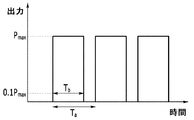
本発明の一実施例による方向性電磁鋼板の磁区の微細化方法は、方向性電磁鋼板を準備する段階と、方向性電磁鋼板の表面にデューティが98.0〜99.9%の準連続レーザービームを照射して溝を形成する段階を行う。ここで、デューティは、レーザービームの出力に対する時間波形において、[出力変調周期時間](Ta)に対する[最大出力(Pmax)の10%以上の出力で照射した時間](Tb)の比(Tb/Ta)である。
The method for refining the magnetic domain of a grain-oriented electrical steel sheet according to an embodiment of the present invention includes a stage of preparing the grain-oriented electrical steel sheet and a semi-continuous laser having a duty of 98.0 to 99.9% on the surface of the grain-oriented electrical steel sheet. The step of irradiating the beam to form a groove is performed. Here, the duty is, in the time waveform for the output of the laser beam, the ratio of the Output modulation period time] (T a) for
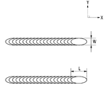
準連続レーザービームの周波数は、100Hz〜8kHzであることができる。準連続レーザービームの幅(W)に対するレーザービームの平均出力(P)の比(P/W)は、30W/μm〜300W/μmであることができる。準連続レーザービームの鋼板の幅方向へのビーム長さ(L)に対する鋼板圧延方向へのビーム幅(W)の比(W/L)は、0.1〜0.86であることができる。準連続レーザービームは、TEM00モードであり、ビーム品質のファクター(factor)であるM2が1.0〜1.1であることができる。
The frequency of the quasi-continuous laser beam can be 100 Hz to 8 kHz. The ratio of the average power of the laser beam relative to a quasi-continuous laser beam width (W) (P) (P / W) can be a 30W / μm ~300W / μm. The ratio (W / L) of the beam width (W) in the steel sheet rolling direction to the beam length (L) in the width direction of the steel sheet of the quasi-continuous laser beam can be 0.1 to 0.86. The quasi-continuous laser beam is in TEM00 mode and can have a beam quality factor of M2 of 1.0 to 1.1.
溝を鋼板の幅方向に断続的に3〜8個形成することができる。溝は線状で、電磁鋼板の圧延方向に対し、82°〜98°の角度で形成することができる。溝の深さ(D)を鋼板の厚さの3%〜8%で形成することができる。 Three to eight grooves can be formed intermittently in the width direction of the steel sheet. The grooves are linear and can be formed at an angle of 82 ° to 98 ° with respect to the rolling direction of the electrical steel sheet. The groove depth (D) can be formed at 3% to 8% of the thickness of the steel sheet.
溝を形成する段階の後に、脱炭焼鈍または窒化焼鈍して鋼板の表面に酸化層を形成する段階と、酸化層が形成された鋼板の表面に焼鈍分離剤を塗布し、高温焼鈍して鋼板の表面に非金属酸化物層を形成する段階をさらに行うことができる。また、非金属酸化物層を形成する段階の後に、非金属酸化物層上に絶縁コート層を形成する段階をさらに行うことができる。 After the groove forming step, decarburization annealing or nitride annealing is performed to form an oxide layer on the surface of the steel sheet, and the surface of the steel sheet on which the oxide layer is formed is coated with an annealing separator and annealed at a high temperature to form the steel sheet. Further steps can be taken to form a non-metal oxide layer on the surface of the sheet. Further, after the step of forming the non-metal oxide layer, the step of forming the insulating coat layer on the non-metal oxide layer can be further performed.
本発明の一実施例によれば、永久磁区の微細化による磁束密度の不均一をなくすことができ、鉄損改善率を向上させることができる。
また、本発明の一実施例によれば、最終絶縁コート後の鋼板および絶縁コート層の密着性に優れる。
According to one embodiment of the present invention, the non-uniformity of the magnetic flux density due to the miniaturization of the permanent magnetic domain can be eliminated, and the iron loss improvement rate can be improved.
Further, according to one embodiment of the present invention, the adhesion between the steel sheet and the insulating coating layer after the final insulating coating is excellent.
第1、第2および第3等の用語は、多様な部分、成分、領域、層および/またはセクションを説明するために使用するが、これらに限定されない。これらの用語は、ある部分、成分、領域、層またはセクションを他の部分、成分、領域、層またはセクションと区別するためにのみ使用される。したがって、以下で叙述する第1の部分、成分、領域、層またはセクションは、本発明の範囲を逸脱しない範囲内で第2の部分、成分、領域、層またはセクションと言うこともできる。ここで使用される専門用語は、単に特定の実施例を説明するためのものであり、本発明を限定することを意図しない。ここで使用される単数表現は、文言がこれと明確に反対の意味を示さない限り複数をも含むものである。明細書で使用される「含む」の意味は、特定の特性、領域、定数、段階、動作、要素および/または成分を具体化し、他の特性、領域、定数、段階、動作、要素および/または成分の存在や付加を除外するものではない。ある部分が他の部分「上に」または「の上に」あると言う場合、これは他の部分のすぐ上にまたは上方にあるか、その間に他の部分を伴うことができる。対照的に、ある部分が他の部分の「すぐ上に」あると言う場合、その間に他の部分が介在しない。 Terms such as first, second and third are used to describe various parts, components, regions, layers and / or sections, but are not limited thereto. These terms are used only to distinguish one part, component, area, layer or section from another part, component, area, layer or section. Therefore, the first part, component, region, layer or section described below can also be referred to as a second part, component, region, layer or section without departing from the scope of the present invention. The terminology used herein is merely for the purpose of describing a particular embodiment and is not intended to limit the invention. The singular representation used here includes multiples unless the wording has a clear opposite meaning. As used herein, the meaning of "contains" embodies a particular property, region, constant, stage, behavior, element and / or component and other properties, region, constant, stage, behavior, element and / or. It does not preclude the presence or addition of ingredients. When we say that one part is "above" or "above" another part, it can be just above or above the other part, or with other parts in between. In contrast, when one part is said to be "just above" another part, there is no other part in between.
他に定義のない限り、本願で用いられる技術用語及び科学用語を含む全ての用語は、本発明が属する技術分野における通常の知識を有する者により普通に理解される意味と同じ意味を持つ。一般に用いられている辞書で定義されているような用語は、関連技術文献と現在開示されている内容に合う意味を持つものと追加解釈され、定義されていない限り理想的や公式的過ぎる意味に解釈されない。 Unless otherwise defined, all terms, including technical and scientific terms used herein, have the same meaning as commonly understood by a person of ordinary knowledge in the technical field to which the present invention belongs. Terms such as those defined in commonly used dictionaries are additionally interpreted as having meanings that match the relevant technical literature and currently disclosed content, meaning too ideal or too formal unless defined. Not interpreted.
以下、本発明の実施例について本発明が属する技術分野における通常の知識を有する者が容易に実施できるように詳細に説明する。しかし、本発明は様々な異なる形態で具現することができ、ここで説明する実施例に限定されない。 Hereinafter, examples of the present invention will be described in detail so that a person having ordinary knowledge in the technical field to which the present invention belongs can easily carry out the examples. However, the present invention can be embodied in a variety of different forms and is not limited to the examples described herein.
本発明の一実施例による方向性電磁鋼板の磁区の微細化方法は、方向性電磁鋼板を準備する段階と、方向性電磁鋼板の表面にデューティが98.0〜99.9%の準連続レーザービームを照射して溝を形成する段階を行う。 The method for refining the magnetic domain of a grain-oriented electrical steel sheet according to an embodiment of the present invention includes a stage of preparing the grain-oriented electrical steel sheet and a semi-continuous laser having a duty of 98.0 to 99.9% on the surface of the grain-oriented electrical steel sheet. The step of irradiating the beam to form a groove is performed.
図1では本発明の一実施例によって磁区の微細化された方向性電磁鋼板10の模式図を示している。図1に示すように、方向性電磁鋼板10の表面には圧延方向に沿って複数個の溝20が形成される。以下では各段階別に詳細に説明する。
FIG. 1 shows a schematic view of a grain-cutting grain-oriented
先ず、方向性電磁鋼板を準備する。本発明の一実施例ではレーザービームの照射条件を制御することによって、磁性を向上させるためのものとして、磁区の微細化の対象となる方向性電磁鋼板は制限なしに用いることができる。特に、方向性電磁鋼板の合金組成とは関係なく本発明の効果が発現する。以下では一例として方向性電磁鋼板の合金成分について説明する。 First, a grain-oriented electrical steel sheet is prepared. In one embodiment of the present invention, the grain-oriented electrical steel sheet to be miniaturized in the magnetic domain can be used without limitation as a means for improving magnetism by controlling the irradiation conditions of the laser beam. In particular, the effect of the present invention is exhibited regardless of the alloy composition of the grain-oriented electrical steel sheet. Below, the alloy component of the grain-oriented electrical steel sheet will be described as an example.
方向性電磁鋼板は、全体組成100重量%を基準にO:0.0020〜0.0080%、Si:2.5〜4.0%、C:0.02〜0.10%、Al:0.02〜0.04%、Mn:0.05〜0.20%、N:0.002〜0.012%、S:0.001%〜0.010%、およびP:0.01〜0.08%で、残部がFeとその他不可避不純物からなっている。不可避不純物としては、Ni、Cr、Sbおよび希土類などがあり、不純物の総重量は0.1重量%以内である。 The grain-oriented electrical steel sheet has O: 0.0020 to 0.0080%, Si: 2.5 to 4.0%, C: 0.02 to 0.10%, Al: 0, based on 100% by weight of the total composition. .02 to 0.04%, Mn: 0.05 to 0.20%, N: 0.002 to 0.012%, S: 0.001% to 0.010%, and P: 0.01 to 0 At .08%, the balance consists of Fe and other unavoidable impurities. Inevitable impurities include Ni, Cr, Sb and rare earths, and the total weight of the impurities is within 0.1% by weight.
合金成分の限定に対する理由は、以下のとおりである。Siは、2.5%以上添加すると、比抵抗を増加させて鉄損を改善させることができるが、4.0%を超えると、板の脆性が増すことによって、機械的特性が低下することがある。Cは、0.02%以上添加されて熱間圧延時の組織を均一にし、連続鋳造で発生する柱状晶組織の成長を抑制することができるが、0.10%を超えると、脱炭焼鈍時間が増加して1次再結晶粒が微細となり、2次再結晶温度が低くなることによって磁性特性が低下することがある。Alは、0.02%以上添加されることによって、窒化物形態で結晶粒成長抑制剤として作用する。しかし、0.04%を超えると、窒化物が析出して抑制剤としての役割が低下することがある。Mnは、0.05%以上添加され、硫化物を形成して結晶粒成長抑制剤の役割をする。しかし、0.20%を超えると、1次再結晶粒を小さくして2次再結晶を不安定にし、Mn酸化物を形成して鉄損となることがある。Nは、0.002%以上添加されて結晶粒成長抑制剤の役割をする。しかし、0.012%を超えると、ブリスター(Blister)の表面欠陥を誘発することがある。Sは、0.001%以上添加され、硫化物を形成して結晶粒成長抑制剤の役割をする。しかし、0.010%を超えると、硫化物が形成して結晶粒成長抑制剤として作用するのが難しくなることがある。Pは、0.01%以上添加されると、{110}<001>集合組織の成長を促進する。しかし、0.08%を超えると、鋼の脆性が増すことがある。Oは、スラブ中に0.0020〜0.0080%含まれた状態で1次再結晶焼鈍過程でOが追加的に鋼板に侵入し、鋼中の酸素含有量を増加させる。したがって、鋼中の酸素含有量が通常の酸素含有量より多い状態で素地鋼板の酸化層が形成され、このような酸化層は、以後2次再結晶焼鈍時のMgの拡散が容易に起きる。したがって、素地鋼板側に侵入したフォルステライトなど非金属酸化物層を形成することができる。 The reasons for limiting the alloy components are as follows. When Si is added in an amount of 2.5% or more, the specific resistance can be increased and the iron loss can be improved, but when it exceeds 4.0%, the brittleness of the plate is increased and the mechanical properties are deteriorated. There is. C can be added in an amount of 0.02% or more to make the structure during hot rolling uniform and suppress the growth of columnar crystal structures generated in continuous casting, but if it exceeds 0.10%, decarburization annealing is performed. As the time increases, the primary recrystallized grains become finer and the secondary recrystallization temperature becomes lower, which may reduce the magnetic properties. When 0.02% or more of Al is added, it acts as a crystal grain growth inhibitor in the form of a nitride. However, if it exceeds 0.04%, nitride may be precipitated and the role as an inhibitor may be reduced. Mn is added in an amount of 0.05% or more to form a sulfide and acts as a crystal grain growth inhibitor. However, if it exceeds 0.20%, the primary recrystallization grains may be reduced to destabilize the secondary recrystallization, and Mn oxide may be formed, resulting in iron loss. N is added in an amount of 0.002% or more and acts as a crystal grain growth inhibitor. However, if it exceeds 0.012%, it may induce surface defects of Blister. S is added in an amount of 0.001% or more to form a sulfide and acts as a crystal grain growth inhibitor. However, if it exceeds 0.010%, sulfide may be formed and it may be difficult to act as a crystal grain growth inhibitor. When P is added in an amount of 0.01% or more, it promotes the growth of {110} <001> texture. However, if it exceeds 0.08%, the brittleness of the steel may increase. In the state where O is contained in the slab at 0.0020 to 0.0080%, O additionally invades the steel sheet in the primary recrystallization annealing process to increase the oxygen content in the steel. Therefore, an oxide layer of the base steel sheet is formed in a state where the oxygen content in the steel is higher than the normal oxygen content, and in such an oxide layer, the diffusion of Mg during the subsequent secondary recrystallization annealing easily occurs. Therefore, it is possible to form a non-metal oxide layer such as forsterite that has penetrated into the base steel plate side.
本発明の一実施例では、方向性電磁鋼板は、スラブから熱間圧延および冷間圧延により所定の厚さで圧延された方向性電磁鋼板を用いている。 In one embodiment of the present invention, the grain-oriented electrical steel sheet is a grain-oriented electrical steel sheet rolled from a slab by hot rolling and cold rolling to a predetermined thickness.
次いで、準備した方向性電磁鋼板の表面に準連続レーザービームを照射して溝を形成する。本発明の一実施例では既に知られているパルスレーザーや連続波レーザーでなく、準連続レーザービームを照射する。具体的にはデューティが98.0〜99.9%の準連続レーザービームを照射する。本発明の一実施例では準連続レーザービームを照射することによって、溝下部に凝固合金層が適切な厚さで均一に形成され、スパッタ再凝固による融着物トラップ(trap)を最小化することによって、磁性を向上させ、絶縁コート層との密着力を確保することができる。 Next, the surface of the prepared grain-oriented electrical steel sheet is irradiated with a quasi-continuous laser beam to form a groove. In one embodiment of the present invention, a quasi-continuous laser beam is irradiated instead of the already known pulsed laser or continuous wave laser. Specifically, a quasi-continuous laser beam having a duty of 98.0 to 99.9% is irradiated. In one embodiment of the present invention, by irradiating a quasi-continuous laser beam, a solidified alloy layer is uniformly formed in the lower portion of the groove with an appropriate thickness, and a fusion trap (trap) due to spatter resolidification is minimized. , The magnetism can be improved and the adhesion with the insulating coat layer can be secured.
図2および図3は準連続レーザービームの出力に対する時間波形を示す。ここで、デューティは、[出力変調周期時間](Ta)に対する[最大出力(Pmax)の10%以上の出力で照射した時間](Tb)の比(Tb/Ta)を意味する。図2のようにレーザービームの出力に対する時間波形がOn/Offで示される場合、デューティは、[出力変調周期時間](Ta)に対する[レーザー照射時間](Tb)の比(Tb/Ta)である。図3のようにレーザービームの出力に対する時間波形がOn/Offでない曲線形態で示される場合、デューティは、[出力変調周期時間](Ta)に対する[最大出力(Pmax)の10%以上の出力で照射した時間](Tb)の比(Tb/Ta)を意味する。
2 and 3 show the time waveform with respect to the output of the quasi-continuous laser beam. Here, duty, refers to the ratio (T b / T a) of the power modulation cycle time] (T a) for
準連続レーザービームのデューティは、98.0〜99.9%である。デューティが過度に小さいと、連続的な線状溝を形成することができず、磁性面で問題が発生することがある。デューティが過度に大きいと、連続発進レーザービームと類似し、溝下部に形成される凝固合金層が過度に薄く形成され、絶縁コート層との密着特性が劣ることになる。 The duty of the quasi-continuous laser beam is 98.0-99.9%. If the duty is too small, a continuous linear groove cannot be formed, which may cause problems on the magnetic surface. If the duty is excessively large, the solidified alloy layer formed in the lower portion of the groove is formed excessively thin, similar to the continuous starting laser beam, and the adhesion property with the insulating coat layer is deteriorated.
準連続レーザービームの周波数は、100Hz〜8kHzである。周波数がこの範囲を超えると、レーザー照射時の溶融物の飛散が異常な挙動を現わすことによって溝下部および側部にスパッタトラップ(Trap)が現れることがある。より具体的には準連続レーザービームの周波数は、3kHz〜6kHzである。 The frequency of the quasi-continuous laser beam is 100 Hz to 8 kHz. When the frequency exceeds this range, spatter traps (Traps) may appear in the lower portion and the side portion of the groove due to the abnormal behavior of the scattering of the melt during laser irradiation. More specifically, the frequency of the quasi-continuous laser beam is 3 kHz to 6 kHz.
準連続レーザービームの幅(W)に対するレーザービームの平均出力(P)の比(P/W)は、30W/μm〜300W/μmである。準連続レーザービームの幅(W)に対するレーザービームの平均出力(P)の比(P/W)を前述した範囲に調節して溝下部に均一な凝固合金層を形成する。準連続レーザービームの幅(W)に対するレーザービームの平均出力(P)の比(P/W)が過度に小さいと、溝下部に形成される凝固合金層の厚さが過度に薄くなるので、その後の脱炭焼鈍時に形成される酸化層の厚さが過度に薄くなる問題がある。準連続レーザービームの幅(W)に対するレーザービームの平均出力(P)の比(P/W)が過度に大きいと、溝下部に形成される凝固合金層の厚さが過度に厚く現れるので、基地部に熱影響が増加する。結局、脱炭焼鈍時の溝下部で再結晶が形成されることによって、2次再結晶が形成されない問題がある。より具体的には準連続レーザービームの幅(W)に対するレーザービームの平均出力(P)の比(P/W)は、35W/μm〜250W/μmである。
The ratio of the average power of the laser beam relative to a quasi-continuous laser beam width (W) (P) (P / W) is 30W / μm ~300W / μm. The ratio (P / W) of the average output (P) of the laser beam to the width (W) of the quasi-continuous laser beam is adjusted to the above-mentioned range to form a uniform solidified alloy layer in the lower portion of the groove. If the ratio (P / W) of the average output (P) of the laser beam to the width (W) of the quasi-continuous laser beam is excessively small, the thickness of the solidified alloy layer formed in the lower portion of the groove becomes excessively thin. There is a problem that the thickness of the oxide layer formed during the subsequent decarburization annealing becomes excessively thin. If the ratio (P / W) of the average output (P) of the laser beam to the width (W) of the quasi-continuous laser beam is excessively large, the thickness of the solidified alloy layer formed in the lower portion of the groove appears to be excessively thick. The thermal effect on the base increases. After all, there is a problem that secondary recrystallization is not formed due to the formation of recrystallization in the lower portion of the groove during decarburization annealing. More specifically the ratio of the average power of the laser beam relative to a quasi-continuous laser beam width (W) (P) (P / W) is 35W / μm ~250W / μm.
図4に、鋼板表面でのレーザービームの形状を概略的に示す。図4に示すように、本発明の一実施例では、レーザービームの形状は楕円形である。レーザービームの形状が楕円形であると、連続的な線状の溝の形成に有利である。具体的には準連続レーザービームの鋼板の幅方向へのビーム長さ(L)に対する鋼板圧延方向へのビーム幅(W)の比(W/L)は、0.1〜0.86である。 FIG. 4 schematically shows the shape of the laser beam on the surface of the steel sheet. As shown in FIG. 4, in one embodiment of the present invention, the shape of the laser beam is elliptical. The elliptical shape of the laser beam is advantageous for the formation of continuous linear grooves. Specifically, the ratio (W / L) of the beam width (W) in the steel sheet rolling direction to the beam length (L) in the width direction of the steel sheet of the quasi-continuous laser beam is 0.1 to 0.86. ..
レーザーは、TEM00モードであり、ビーム品質ファクター(factor)であるM2が1.0〜1.1である。この時、用いられるレーザーの出力は、0.5〜5kWである。 The laser is in TEM 00 mode and has a beam quality factor (factor) of M 2 of 1.0 to 1.1. At this time, the output of the laser used is 0.5 to 5 kW.
また、溝20は、電磁鋼板の圧延方向に対し82°〜98°で形成する。溝20を90°を含まない斜線型で形成することによって、反磁場を弱化させて磁性を向上させることができる。
Further, the
溝20は、鋼板の幅方向に断続的に3〜8個形成する。溝の深さ(D)を、鋼板の厚さの3%〜8%で形成する。深さが過度に浅いと、、鉄損改善効果が低く、深さが過度に深いと、熱影響部が増加してゴス集合組織(Goss Texture)の成長に悪影響を与えることがある。
Three to eight
溝を形成する段階を行った後に、脱炭焼鈍または窒化焼鈍して鋼板の表面に酸化層を形成する段階と、酸化層が形成された鋼板の表面に焼鈍分離剤を塗布し、高温焼鈍して鋼板の表面に非金属酸化物層を形成する段階とをさらに行うことができる。 After performing the step of forming grooves, decarburization annealing or nitride annealing is performed to form an oxide layer on the surface of the steel sheet, and the surface of the steel sheet on which the oxide layer is formed is coated with an annealing separator and annealed at high temperature. The step of forming a non-metal oxide layer on the surface of the steel sheet can be further performed.
酸化層を形成する段階(すなわち、1次再結晶焼鈍)は、脱炭焼鈍以後に窒化焼鈍するか、脱炭焼鈍および窒化焼鈍を同時に行うこともできる。1次再結晶焼鈍時の焼鈍温度は、700〜950℃である。1次再結晶焼鈍時の脱炭のために酸化性雰囲気に制御する。この時、鋼板に含まれたSiは、脱炭焼鈍雰囲気ガスに存在する水分と反応して鋼板の表層部に酸化層を形成する。1次再結晶焼鈍における脱炭は、鋼板内部の炭素が表面に拡散して行い、一方で鋼板は、雰囲気ガスに含まれた酸素と反応してSiO2やFe2SiO4(Faylite)のような酸化層を表面に形成する。この時、1次再結晶焼鈍の過程において、鋼板の表面に形成される酸化層におけるSiO2/Fe2SiO4の重量比は0.1〜1.5である。 The step of forming the oxide layer (that is, primary recrystallization annealing) can be nitriding annealing after decarburization annealing, or decarburization annealing and nitriding annealing can be performed at the same time. The annealing temperature at the time of primary recrystallization annealing is 700 to 950 ° C. The oxidative atmosphere is controlled for decarburization during primary recrystallization annealing. At this time, Si contained in the steel sheet reacts with the water present in the decarburized annealing atmosphere gas to form an oxide layer on the surface layer portion of the steel sheet. Decarburization in the primary recrystallization annealing is performed by diffusing the carbon inside the steel sheet to the surface, while the steel sheet reacts with oxygen contained in the atmospheric gas to form SiO 2 or Fe 2 SiO 4 (Faylite). An oxide layer is formed on the surface. At this time, in the process of primary recrystallization annealing, the weight ratio of SiO 2 / Fe 2 SiO 4 in the oxide layer formed on the surface of the steel sheet is 0.1 to 1.5.
このように1次再結晶焼鈍過程で形成される酸化層の重量比は、1次再結晶焼鈍、すなわち、脱炭焼鈍時の適正な酸素投入量と密接な関係がある。鋼板の成分のうち酸素含有量を通常の酸素含有量より多く含ませた状態で脱炭焼鈍時の酸素投入量を制御する。脱炭焼鈍時の酸素の投入量は、酸化性雰囲気(露点、水素雰囲気)と鋼板表層部の酸化層の形状、および鋼板の温度を考慮しなければならない。 As described above, the weight ratio of the oxide layer formed in the primary recrystallization annealing process is closely related to the primary recrystallization annealing, that is, the appropriate amount of oxygen input during decarburization annealing. The amount of oxygen input during decarburization annealing is controlled in a state where the oxygen content of the steel sheet is larger than the normal oxygen content. The amount of oxygen input during decarburization annealing must take into consideration the oxidizing atmosphere (dew point, hydrogen atmosphere), the shape of the oxide layer on the surface layer of the steel sheet, and the temperature of the steel sheet.
酸化能だけで判断すると、酸化能が高いほど酸素分圧が高まるので、酸化能を高めた方が良い。しかし、酸化能が過度に高くなると、表層部にSiO2やFe2SiO4(Faylite)酸化物が鋼板の表層部に緻密に形成される。このように緻密な酸化物が形成されると酸素の深さ方向への浸透を妨害する妨害物の役割をし、結果的に酸素の鋼板内部への浸透を妨害する。したがって、脱炭のための適切な酸化能が存在するので、790〜900℃の温度範囲で露点50〜70℃(50%N2+50%H2)雰囲気で脱炭が都合よく起こり、適切な酸化層が形成される。脱炭焼鈍時の脱炭雰囲気を制御して脱炭焼鈍を完了すると、鋼板表面の酸素層の酸素量は、600〜1,000ppm範囲にある。 Judging from the oxidative capacity alone, the higher the oxidative capacity, the higher the oxygen partial pressure, so it is better to increase the oxidative capacity. However, when the oxidizing ability becomes excessively high, SiO 2 or Fe 2 SiO 4 (Faylite) oxide is densely formed on the surface layer portion of the steel sheet. When such a dense oxide is formed, it acts as an obstacle that hinders the permeation of oxygen in the depth direction, and as a result, hinders the permeation of oxygen into the steel sheet. Therefore, since there is an appropriate oxidizing ability for decarburization, decarburization conveniently occurs in an atmosphere with a dew point of 50 to 70 ° C. (50% N 2 + 50% H 2) in the temperature range of 790 to 900 ° C. An oxide layer is formed. When the decarburization annealing is completed by controlling the decarburization atmosphere at the time of decarburization annealing, the oxygen content of the oxygen layer on the surface of the steel sheet is in the range of 600 to 1,000 ppm.
次に、酸化層が形成された鋼板の表面に焼鈍分離剤を塗布し、高温焼鈍(すなわち、2次再結晶焼鈍)して鋼板の表面に非金属酸化物層を形成する。焼鈍分離剤は、MgOを主成分とするスラリー状で、ここに反応促進剤としてTi化合物、Cl化合物、硫化物、窒化物、窒化物または酸化物の一種または一種以上を混合して加える。焼鈍分離剤は、スラリー状であるので、鋼板にコーティングロールによって塗布ができ、その塗布量を、鋼板の片面当たり2.0〜12.5g/m2とするのが好ましい。焼鈍分離剤は、2次再結晶焼鈍時、焼鈍分離剤の主成分であるMgOが酸化層のSiO2または/およびFe2SiO4と反応してフォルステライト(Forsterite;Mg2SiO4)ガラス被膜を形成する。このようなフォルステライト被膜は、2次再結晶焼鈍過程でインヒビター挙動に影響を与え、電磁鋼板の磁気特性に影響を与え、被膜が形成された後には素地鋼板との密着性などのような被膜特性にも影響を及ぼす。焼鈍分離剤の主成分であるMgOの平均粉末粒径が2.5μm以下のものを使用することが好ましく、その中で平均粉末粒径が2μm以下が10%以上であることがさらに好ましい。 Next, an annealing separator is applied to the surface of the steel sheet on which the oxide layer is formed, and high-temperature annealing (that is, secondary recrystallization annealing) is performed to form a non-metal oxide layer on the surface of the steel sheet. The annealing separator is in the form of a slurry containing MgO as a main component, to which one or more of Ti compound, Cl compound, sulfide, nitride, nitride or oxide is mixed and added as a reaction accelerator. Since the annealing separator is in the form of a slurry, it can be applied to a steel sheet with a coating roll, and the coating amount is preferably 2.0 to 12.5 g / m 2 per one side of the steel sheet. Annealing separating agent, when the secondary recrystallization annealing, MgO which is the main component of the annealing separator reacts with SiO 2 and / or Fe 2 SiO 4 of the oxide layer forsterite (Forsterite; Mg 2 SiO 4) Glass coating To form. Such a forsterite film affects the inhibitor behavior in the secondary recrystallization annealing process, affects the magnetic properties of the electrical steel sheet, and after the film is formed, it is a film such as adhesion to the base steel sheet. It also affects the characteristics. It is preferable to use MgO having an average powder particle size of 2.5 μm or less, which is the main component of the annealing separator, and it is more preferable that the average powder particle size of 2 μm or less is 10% or more.
一方、2次再結晶焼鈍は、550〜750℃での1次亀裂過程と1,000〜1,250℃での2次亀裂過程に分けて行い、昇温区間は、650〜950℃の温度区間では時間当り30〜100℃に昇温し、950〜1,250℃の温度区間では時間当り50℃以下に昇温する。そして、亀裂時間は、1次亀裂過程は、焼鈍分離剤の水分を除去するために10分以上にし、2次亀裂時間は8時間以上にする。2次再結晶焼鈍時雰囲気は、2次亀裂温度までは窒素と水素の混合雰囲気で行い、2次亀裂温度に到達した後には水素雰囲気で行うことが好ましい。以上のようにMgOを主成分とする焼鈍分離剤を塗布して2次再結晶焼鈍を行うと、焼鈍過程で焼鈍分離剤のうちMgが素地鋼板の内部に拡散し、脱炭焼鈍過程で生成されたSi酸化物とMgが相互拡散反応をしながらフォルステライトを形成する。2次再結晶焼鈍過程で鋼板の内部でゴス核を有する結晶から(110)<001>ゴス方位を有する結晶粒がまず成長して優れた電気的特性を持つ。非金属酸化物層は、例示したMg2SiO4の他に、Al2SiO4やMn2SiO4であってもよい。 On the other hand, the secondary recrystallization annealing is divided into a primary cracking process at 550 to 750 ° C. and a secondary cracking process at 1,000 to 1,250 ° C., and the temperature rise section is a temperature of 650 to 950 ° C. In the section, the temperature is raised to 30 to 100 ° C. per hour, and in the temperature section of 950 to 1,250 ° C., the temperature is raised to 50 ° C. or less per hour. The crack time is set to 10 minutes or more for the primary crack process to remove the water content of the annealing separator, and 8 hours or more for the secondary crack time. It is preferable that the atmosphere at the time of secondary recrystallization annealing is a mixed atmosphere of nitrogen and hydrogen up to the secondary crack temperature, and is carried out in a hydrogen atmosphere after reaching the secondary crack temperature. When the annealing separator containing MgO as the main component is applied and the secondary recrystallization annealing is performed as described above, Mg among the annealing separators diffuses inside the base steel sheet in the annealing process and is generated in the decarburization annealing process. The Si oxide and Mg form a forsterite while undergoing a mutual diffusion reaction. In the process of secondary recrystallization annealing, crystal grains having (110) <001> Goth orientation first grow from crystals having Goth nuclei inside the steel sheet, and have excellent electrical characteristics. The non-metal oxide layer may be Al 2 SiO 4 or Mn 2 SiO 4 in addition to the illustrated Mg 2 SiO 4.
非金属酸化物層を形成する段階の後、さらに非金属酸化物層上に絶縁コート層を形成する段階を行うことができる。具体的な方法として、リン酸塩を含む絶縁コート液を塗布する方式で絶縁コート層を形成し得る。このような絶縁コート液は、コロイダルシリカと金属リン酸塩を含むコート液を使用することが好ましい。この時、金属リン酸塩は、Alリン酸塩、Mgリン酸塩、またはこれらの組み合わせが可能で、絶縁コート液の重量に対してAl、Mg、またはこれらの組み合わせの含有量は15重量%以上である。絶縁コート層を形成させた後に、応力緩和焼鈍をさらに行うことができる。 After the step of forming the non-metal oxide layer, a step of further forming an insulating coat layer on the non-metal oxide layer can be performed. As a specific method, the insulating coat layer can be formed by applying an insulating coating liquid containing a phosphate. As such an insulating coating liquid, it is preferable to use a coating liquid containing colloidal silica and metal phosphate. At this time, the metal phosphate can be Al phosphate, Mg phosphate, or a combination thereof, and the content of Al, Mg, or a combination thereof is 15% by weight based on the weight of the insulating coating liquid. That is all. After forming the insulating coat layer, further stress relaxation annealing can be performed.
以下では実施例により本発明をさらに詳細に説明する。しかし、このような実施例は、単に本発明を例示するためであり、本発明はこれに限定されるものではない。 Hereinafter, the present invention will be described in more detail by way of examples. However, such examples are merely for exemplifying the present invention, and the present invention is not limited thereto.
冷間圧延した厚さ0.27mmの方向性電磁鋼板を準備した。この電磁鋼板の表面に、TEM00モードで、ビーム品質ファクターであるM2が1.0、出力を2.8kWに調節したレーザーを照射した。この時、レーザービームの形状、デューティ、周波数、P/W値を下記表1および表2のように変えながら照射した。次いで、脱炭焼鈍および窒化処理を行い、MgOを主成分とする焼鈍分離剤を鋼板片面当たり8g/m2になるように塗布した後鋼板の2次再結晶焼鈍を行った。その後、コロイダルシリカと金属リン酸塩を含む絶縁コート液をコートして絶縁コート層を形成した。 A cold-rolled grain-oriented electrical steel sheet having a thickness of 0.27 mm was prepared. The surface of this electrical steel sheet was irradiated with a laser in TEM 00 mode in which the beam quality factor M 2 was adjusted to 1.0 and the output was adjusted to 2.8 kW. At this time, irradiation was performed while changing the shape, duty, frequency, and P / W value of the laser beam as shown in Tables 1 and 2 below. Next, decarburization annealing and nitriding treatment were performed, and an annealing separator containing MgO as a main component was applied so as to be 8 g / m 2 per one side of the steel sheet, and then secondary recrystallization annealing of the steel sheet was performed. Then, an insulating coating liquid containing colloidal silica and a metal phosphate was coated to form an insulating coating layer.

表1および表2において、鉄損改善率は、レーザーを照射して溝を形成する前の電磁鋼板の鉄損(W1)とレーザーを照射して溝を形成した後の鉄損(W2)を測定して(W1−W2)/W1で計算した。密着性は、円形型Bar(直径5〜80mm)に鋼板を密着させてBendingさせたとき、絶縁コーティングおよび非金属酸化物層の剥離あるいは脱着が起きるかをBar直径で表示した。 In Table 1 and Table 2, the iron loss improvement rate of iron loss of the electromagnetic steel sheet before forming a groove by irradiating a laser (W 1) and iron loss after forming a groove by irradiating a laser (W 2 ) Was measured and calculated by (W 1 − W 2 ) / W 1 . The adhesion was indicated by the Bar diameter as to whether the insulating coating and the non-metal oxide layer were peeled off or detached when the steel plate was adhered to the circular Bar (diameter 5 to 80 mm) and bent.
表1および表2に示すように、準連続レーザーを用いると、鉄損改善率および密着性が同時に向上することを確認することができる。反面、準連続レーザーを用いてもデューティが低く、連続レーザーを用いると、密着性が劣ることがわかる。また、パルスレーザーを用いると、鉄損改善率および密着性が同時に劣ることが確認できる。準連続レーザーを用いてP/W値を適切に調節したとき、鉄損改善率および密着性がさらに向上することを確認することができる。デューティが95%で低い場合、溝が生じる部位と生じない部位が板の長さ方向のスキャンした線上に現れるので、線が形成された部位には溝が現れるが、線が形成されていない部位では溝が形成されない。したがって、鉄損値は統計的に約1.3%程度改善される。 As shown in Tables 1 and 2, it can be confirmed that the iron loss improvement rate and the adhesion are improved at the same time by using the semi-continuous laser. On the other hand, it can be seen that the duty is low even when a quasi-continuous laser is used, and the adhesion is inferior when a continuous laser is used. Further, when a pulse laser is used, it can be confirmed that the iron loss improvement rate and the adhesion are at the same time inferior. It can be confirmed that the iron loss improvement rate and the adhesion are further improved when the P / W value is appropriately adjusted by using the quasi-continuous laser. When the duty is as low as 95%, the part where the groove is formed and the part where the groove is not formed appear on the scanned line in the length direction of the plate, so that the part where the line is formed has a groove but the part where the line is not formed. Does not form a groove. Therefore, the iron loss value is statistically improved by about 1.3%.
本発明は実施例に限定されるものではなく、互いに異なる多様な形態で製造でき、本発明が属する技術分野における通常の知識を有する者は、本発明の技術的思想や必須の特徴を変更せず、他の具体的な形態で実施できることを理解することができる。したがって、上記実施例はすべての面で例示的なものであり、限定的なものではないと理解しなければならない。 The present invention is not limited to the examples, and can be produced in various forms different from each other, and a person having ordinary knowledge in the technical field to which the present invention belongs can change the technical idea and essential features of the present invention. However, it can be understood that it can be carried out in other concrete forms. Therefore, it should be understood that the above embodiments are exemplary in all respects and are not limiting.
10 電磁鋼板
20 溝
10
Claims (9)
レーザービームの出力に対する時間波形において、[出力変調周期時間](Ta)に対する[最大出力(Pmax)の10%以上の出力で照射した時間](Tb)の比(Tb/Ta)をデューティとして、前記デューティが98.0〜99.9%の準連続レーザービームを前記鋼板の表面に照射して溝を形成する段階と、を行ない、
前記準連続レーザービームの幅(W)に対するレーザービームの平均出力(P)の比(P/W)は、30W/μm〜300W/μmであることを特徴とする方向性電磁鋼板の磁区の微細化方法。 At the stage of preparing hot-rolled and cold-rolled steel sheets from slabs,
In the time waveform with respect to the output of the laser beam, the ratio (Tb / Ta) of [irradiation time at an output of 10% or more of the maximum output (Pmax)] (Tb) to [output modulation cycle time] (Ta) is defined as duty. the duty no line and forming a groove by irradiating a quasi-continuous laser beam of 98.0 to 99.9% on the surface of the steel sheet,
The ratio (P / W) of the average output (P) of the laser beam to the width (W) of the quasi-continuous laser beam is 30 W / μm to 300 W / μm, and the magnetic domain of the directional electromagnetic steel plate is fine. How to convert.
脱炭焼鈍して鋼板の表面に酸化層を形成する段階と、
前記酸化層が形成された鋼板の表面に焼鈍分離剤を塗布して高温焼鈍して鋼板の表面に非金属酸化物層を形成する段階と、
をさらに行うことを特徴とする請求項1乃至請求項7のいずれか一項に記載の方向性電磁鋼板の磁区の微細化方法。 After the step of forming the groove,
Forming an oxide layer on the surface of the de-charcoal blunt to steel,
A step of applying an annealing separator to the surface of the steel sheet on which the oxide layer is formed and annealing at high temperature to form a non-metal oxide layer on the surface of the steel sheet.
The method for miniaturizing a magnetic domain of a grain-oriented electrical steel sheet according to any one of claims 1 to 7, wherein the method is further performed.
前記非金属酸化物層上に絶縁コート層を形成する段階をさらに行うことを特徴とする請求項8に記載の方向性電磁鋼板の磁区の微細化方法。
After the step of forming the non-metal oxide layer,
The method for miniaturizing a magnetic domain of a grain-oriented electrical steel sheet according to claim 8 , further comprising a step of forming an insulating coat layer on the non-metal oxide layer.
Applications Claiming Priority (3)
| Application Number | Priority Date | Filing Date | Title |
|---|---|---|---|
| KR1020160177082A KR101944899B1 (en) | 2016-12-22 | 2016-12-22 | Method for refining magnetic domains of grain oriented electrical steel sheet |
| KR10-2016-0177082 | 2016-12-22 | ||
| PCT/KR2017/015128 WO2018131819A1 (en) | 2016-12-22 | 2017-12-20 | Method for refining magnetic domains of grain-oriented electrical steel sheet |
Publications (2)
| Publication Number | Publication Date |
|---|---|
| JP2020504783A JP2020504783A (en) | 2020-02-13 |
| JP6832434B2 true JP6832434B2 (en) | 2021-02-24 |
Family
ID=62839811
Family Applications (1)
| Application Number | Title | Priority Date | Filing Date |
|---|---|---|---|
| JP2019534755A Active JP6832434B2 (en) | 2016-12-22 | 2017-12-20 | Method for miniaturizing magnetic domains of grain-oriented electrical steel sheets |
Country Status (6)
| Country | Link |
|---|---|
| US (1) | US11313011B2 (en) |
| EP (1) | EP3561088A4 (en) |
| JP (1) | JP6832434B2 (en) |
| KR (1) | KR101944899B1 (en) |
| CN (1) | CN110100018B (en) |
| WO (1) | WO2018131819A1 (en) |
Families Citing this family (6)
| Publication number | Priority date | Publication date | Assignee | Title |
|---|---|---|---|---|
| KR102221606B1 (en) * | 2018-11-30 | 2021-02-26 | 주식회사 포스코 | Method for manufacturing grain oriented electrical steel sheet |
| KR102164329B1 (en) * | 2018-12-19 | 2020-10-12 | 주식회사 포스코 | Grain oriented electrical steel sheet and method for manufacturing therof |
| KR102428854B1 (en) * | 2019-12-20 | 2022-08-02 | 주식회사 포스코 | Grain oriented electrical steel sheet and method for refining magnetic domains therein |
| US20210229217A1 (en) * | 2020-01-27 | 2021-07-29 | National Technology & Engineering Solutions Of Sandia, Llc | Methods for site-specific enhancement of soft magnetic alloys |
| JP6977814B2 (en) * | 2020-05-15 | 2021-12-08 | Jfeスチール株式会社 | Method for forming linear grooves and method for manufacturing grain-oriented electrical steel sheets |
| KR102415741B1 (en) * | 2020-12-21 | 2022-06-30 | 주식회사 포스코 | Grain oriented electrical steel sheet and method for refining magnetic domains therein |
Family Cites Families (17)
| Publication number | Priority date | Publication date | Assignee | Title |
|---|---|---|---|---|
| US4963199A (en) | 1988-10-14 | 1990-10-16 | Abb Power T&D Company, Inc. | Drilling of steel sheet |
| WO1997024466A1 (en) * | 1995-12-27 | 1997-07-10 | Nippon Steel Corporation | Magnetic steel sheet having excellent magnetic properties and method for manufacturing the same |
| JP4189143B2 (en) | 2001-10-22 | 2008-12-03 | 新日本製鐵株式会社 | Low iron loss unidirectional electrical steel sheet manufacturing method |
| KR100676936B1 (en) * | 2003-03-19 | 2007-02-02 | 신닛뽄세이테쯔 카부시키카이샤 | Grain-oriented magnetic steel sheet excellent in magnetic characteristic and its manufacturing method |
| JP5000182B2 (en) * | 2006-04-07 | 2012-08-15 | 新日本製鐵株式会社 | Method for producing grain-oriented electrical steel sheet with excellent magnetic properties |
| CN102834529A (en) | 2010-04-01 | 2012-12-19 | 新日本制铁株式会社 | Directional electromagnetic steel plate and method for manufacturing same |
| JP5919617B2 (en) | 2010-08-06 | 2016-05-18 | Jfeスチール株式会社 | Oriented electrical steel sheet and manufacturing method thereof |
| JP5998424B2 (en) | 2010-08-06 | 2016-09-28 | Jfeスチール株式会社 | Oriented electrical steel sheet |
| WO2012033197A1 (en) | 2010-09-09 | 2012-03-15 | 新日本製鐵株式会社 | Oriented electromagnetic steel sheet and process for production thereof |
| CN103814317A (en) * | 2011-09-14 | 2014-05-21 | Imra美国公司 | Controllable multi-wavelength fiber laser source |
| RU2569267C1 (en) * | 2011-10-04 | 2015-11-20 | ДжФЕ СТИЛ КОРПОРЕЙШН | Annealing separator for grain-oriented electrical sheet steel |
| KR101370634B1 (en) * | 2011-12-29 | 2014-03-07 | 주식회사 포스코 | Grain-oriented electrical steel sheet and method for manufacturing the same |
| US10131018B2 (en) * | 2012-04-27 | 2018-11-20 | Nippon Steel & Sumitomo Metal Corporation | Grain-oriented magnetic steel sheet and method of producing the same |
| PL2918689T3 (en) * | 2012-11-08 | 2020-07-27 | Nippon Steel Corporation | Laser processing apparatus and laser irradiation method |
| KR101565509B1 (en) | 2013-12-23 | 2015-11-03 | 주식회사 포스코 | Grain-oriented electrical steel sheet and method for manufacturing the same |
| KR101719231B1 (en) * | 2014-12-24 | 2017-04-04 | 주식회사 포스코 | Grain oriented electical steel sheet and method for manufacturing the same |
| KR101659350B1 (en) * | 2016-02-11 | 2016-09-23 | 주식회사 포스코 | Grain-oriented electrical steel sheet and method for manufacturing the same |
-
2016
- 2016-12-22 KR KR1020160177082A patent/KR101944899B1/en active IP Right Grant
-
2017
- 2017-12-20 CN CN201780080297.9A patent/CN110100018B/en active Active
- 2017-12-20 WO PCT/KR2017/015128 patent/WO2018131819A1/en unknown
- 2017-12-20 EP EP17891326.5A patent/EP3561088A4/en active Pending
- 2017-12-20 JP JP2019534755A patent/JP6832434B2/en active Active
- 2017-12-20 US US16/472,484 patent/US11313011B2/en active Active
Also Published As
| Publication number | Publication date |
|---|---|
| CN110100018A (en) | 2019-08-06 |
| EP3561088A4 (en) | 2019-11-27 |
| CN110100018B (en) | 2021-05-25 |
| US20210130922A1 (en) | 2021-05-06 |
| US11313011B2 (en) | 2022-04-26 |
| KR101944899B1 (en) | 2019-02-01 |
| KR20180073343A (en) | 2018-07-02 |
| JP2020504783A (en) | 2020-02-13 |
| WO2018131819A1 (en) | 2018-07-19 |
| EP3561088A1 (en) | 2019-10-30 |
Similar Documents
| Publication | Publication Date | Title |
|---|---|---|
| JP6832434B2 (en) | Method for miniaturizing magnetic domains of grain-oriented electrical steel sheets | |
| JP6928094B2 (en) | Directional electromagnetic steel sheet and its magnetic domain miniaturization method | |
| JP6655084B2 (en) | Grain-oriented electrical steel sheet and its manufacturing method | |
| KR101499404B1 (en) | Method of producing grain-oriented electrical steel sheet | |
| EP2602344B1 (en) | Oriented electromagnetic steel plate | |
| JP5754097B2 (en) | Oriented electrical steel sheet and manufacturing method thereof | |
| CN107109552A (en) | Low iron loss orientation electromagnetic steel plate and its manufacture method | |
| JP6084351B2 (en) | Oriented electrical steel sheet and manufacturing method thereof | |
| JP4916847B2 (en) | Manufacturing method of unidirectional electrical steel sheet | |
| WO2012001952A1 (en) | Oriented electromagnetic steel plate and production method for same | |
| JP5842410B2 (en) | Method for producing grain-oriented electrical steel sheet | |
| CN114829639B (en) | Oriented electrical steel sheet and method for refining magnetic domains thereof | |
| JP7365416B2 (en) | Grain-oriented electrical steel sheet and its manufacturing method | |
| CN113228204B (en) | Oriented electrical steel sheet and method for manufacturing same | |
| CN113196423B (en) | Oriented electrical steel sheet and method for manufacturing same | |
| CN113243034B (en) | Oriented electrical steel sheet and method for manufacturing same | |
| WO2023112421A1 (en) | Grain-oriented electromagnetic steel sheet and method for producing same | |
| JP2002194444A (en) | Method for producing grain oriented electrical steel sheet having excellent magnetic characteristic and film characteristic |
Legal Events
| Date | Code | Title | Description |
|---|---|---|---|
| A521 | Request for written amendment filed |
Free format text: JAPANESE INTERMEDIATE CODE: A523 Effective date: 20190624 |
|
| A621 | Written request for application examination |
Free format text: JAPANESE INTERMEDIATE CODE: A621 Effective date: 20190624 |
|
| A977 | Report on retrieval |
Free format text: JAPANESE INTERMEDIATE CODE: A971007 Effective date: 20200422 |
|
| A131 | Notification of reasons for refusal |
Free format text: JAPANESE INTERMEDIATE CODE: A131 Effective date: 20200609 |
|
| A521 | Request for written amendment filed |
Free format text: JAPANESE INTERMEDIATE CODE: A523 Effective date: 20200909 |
|
| TRDD | Decision of grant or rejection written | ||
| A01 | Written decision to grant a patent or to grant a registration (utility model) |
Free format text: JAPANESE INTERMEDIATE CODE: A01 Effective date: 20210105 |
|
| A61 | First payment of annual fees (during grant procedure) |
Free format text: JAPANESE INTERMEDIATE CODE: A61 Effective date: 20210201 |
|
| R150 | Certificate of patent or registration of utility model |
Ref document number: 6832434 Country of ref document: JP Free format text: JAPANESE INTERMEDIATE CODE: R150 |
|
| S531 | Written request for registration of change of domicile |
Free format text: JAPANESE INTERMEDIATE CODE: R313531 |
|
| S533 | Written request for registration of change of name |
Free format text: JAPANESE INTERMEDIATE CODE: R313533 |
|
| R350 | Written notification of registration of transfer |
Free format text: JAPANESE INTERMEDIATE CODE: R350 |
|
| S111 | Request for change of ownership or part of ownership |
Free format text: JAPANESE INTERMEDIATE CODE: R313113 |
|
| R371 | Transfer withdrawn |
Free format text: JAPANESE INTERMEDIATE CODE: R371 |
|
| S111 | Request for change of ownership or part of ownership |
Free format text: JAPANESE INTERMEDIATE CODE: R313113 |
|
| R350 | Written notification of registration of transfer |
Free format text: JAPANESE INTERMEDIATE CODE: R350 |
|
| R250 | Receipt of annual fees |
Free format text: JAPANESE INTERMEDIATE CODE: R250 |