JP6832324B2 - Toilet seat - Google Patents
Toilet seat Download PDFInfo
- Publication number
- JP6832324B2 JP6832324B2 JP2018215621A JP2018215621A JP6832324B2 JP 6832324 B2 JP6832324 B2 JP 6832324B2 JP 2018215621 A JP2018215621 A JP 2018215621A JP 2018215621 A JP2018215621 A JP 2018215621A JP 6832324 B2 JP6832324 B2 JP 6832324B2
- Authority
- JP
- Japan
- Prior art keywords
- toilet seat
- seat
- cushion body
- toilet
- comparative example
- Prior art date
- Legal status (The legal status is an assumption and is not a legal conclusion. Google has not performed a legal analysis and makes no representation as to the accuracy of the status listed.)
- Active
Links
- 239000000463 material Substances 0.000 claims description 44
- 210000001217 buttock Anatomy 0.000 claims description 12
- 239000012790 adhesive layer Substances 0.000 claims description 10
- 239000010410 layer Substances 0.000 claims description 6
- 230000002093 peripheral effect Effects 0.000 claims description 5
- 229920005830 Polyurethane Foam Polymers 0.000 claims description 4
- 239000004745 nonwoven fabric Substances 0.000 claims description 4
- 239000011496 polyurethane foam Substances 0.000 claims description 4
- 230000000052 comparative effect Effects 0.000 description 53
- 230000008859 change Effects 0.000 description 35
- 238000002474 experimental method Methods 0.000 description 34
- 238000009826 distribution Methods 0.000 description 23
- 238000005259 measurement Methods 0.000 description 14
- 210000005037 parasympathetic nerve Anatomy 0.000 description 14
- 210000000467 autonomic pathway Anatomy 0.000 description 13
- 230000035487 diastolic blood pressure Effects 0.000 description 13
- 230000035488 systolic blood pressure Effects 0.000 description 12
- 238000010586 diagram Methods 0.000 description 9
- 230000006870 function Effects 0.000 description 9
- 238000012795 verification Methods 0.000 description 8
- 238000000034 method Methods 0.000 description 7
- 230000000630 rising effect Effects 0.000 description 5
- 230000002567 autonomic effect Effects 0.000 description 4
- 230000036772 blood pressure Effects 0.000 description 4
- 208000002173 dizziness Diseases 0.000 description 4
- 230000035807 sensation Effects 0.000 description 4
- 230000000694 effects Effects 0.000 description 3
- 238000004140 cleaning Methods 0.000 description 2
- 229920001577 copolymer Polymers 0.000 description 2
- 230000001877 deodorizing effect Effects 0.000 description 2
- 230000006353 environmental stress Effects 0.000 description 2
- 239000000835 fiber Substances 0.000 description 2
- 230000005484 gravity Effects 0.000 description 2
- 238000010438 heat treatment Methods 0.000 description 2
- 239000012943 hotmelt Substances 0.000 description 2
- 208000013433 lightheadedness Diseases 0.000 description 2
- 238000010128 melt processing Methods 0.000 description 2
- 238000003825 pressing Methods 0.000 description 2
- 230000004044 response Effects 0.000 description 2
- 229920003002 synthetic resin Polymers 0.000 description 2
- 239000000057 synthetic resin Substances 0.000 description 2
- 229920001169 thermoplastic Polymers 0.000 description 2
- 239000004416 thermosoftening plastic Substances 0.000 description 2
- 206010005746 Blood pressure fluctuation Diseases 0.000 description 1
- VVQNEPGJFQJSBK-UHFFFAOYSA-N Methyl methacrylate Chemical compound COC(=O)C(C)=C VVQNEPGJFQJSBK-UHFFFAOYSA-N 0.000 description 1
- 230000009471 action Effects 0.000 description 1
- 239000000839 emulsion Substances 0.000 description 1
- 239000000945 filler Substances 0.000 description 1
- 230000008717 functional decline Effects 0.000 description 1
- 238000002156 mixing Methods 0.000 description 1
- 238000012986 modification Methods 0.000 description 1
- 230000004048 modification Effects 0.000 description 1
- 210000005036 nerve Anatomy 0.000 description 1
- 230000001734 parasympathetic effect Effects 0.000 description 1
- 229920000728 polyester Polymers 0.000 description 1
- 238000004080 punching Methods 0.000 description 1
- 238000005096 rolling process Methods 0.000 description 1
- 230000035882 stress Effects 0.000 description 1
- 230000002889 sympathetic effect Effects 0.000 description 1
Images


Landscapes
- Toilet Supplies (AREA)
Description
本発明は、便座の座部に覆うように装着される便座シートに関する。 The present invention relates to a toilet seat seat that is attached so as to cover the seat portion of the toilet seat.
洋式便器の便座には、着座時の触感を良好にすることを目的として、便座シート(便座カバー)が装着されることがある。近年においては、温熱、洗浄、消臭等の付加機能を有し、形態が種々に異なる便座が存在しており、これらの便座に共通して使用し得る便座シートが提案されている(例えば、特許文献1参照)。 A toilet seat (toilet seat cover) may be attached to the toilet seat of a Western-style toilet bowl for the purpose of improving the tactile sensation when seated. In recent years, there are toilet seats having additional functions such as heating, cleaning, and deodorizing, and having various forms, and toilet seat seats that can be commonly used for these toilet seats have been proposed (for example,). See Patent Document 1).
特許文献1に記載の便座シートは、弓形の湾曲形状を有しており、便座への着座時に身体に接触する左右の座部を夫々覆うように装着される。該便座シートは、更に、座部に載置される基材と身体に接触する表面材との間にクッション体を介装し、表面材の触感と共にクッション体の弾性を使用者に体感させ、使用感の改善を図っている。
The toilet seat seat described in
特許文献1に記載の便座シートは、クッション体の作用により、硬質の便座に着座する際の身体的負担を和らげることができ、特に、高齢者に有用である。また、クッション体の弾性は便座からの立ち上がりを補助する作用もあるが、この補助作用は十分ではない。
The toilet seat seat described in
本発明は斯かる事情に鑑みてなされたものであり、便座からの立ち上がりを良好に補助することができる便座シートを提供することを目的とする。 The present invention has been made in view of such circumstances, and an object of the present invention is to provide a toilet seat seat that can satisfactorily assist in getting up from the toilet seat.
本開示の実施形態に係る便座シートは、便座の座部に覆うように装着され、前記座部に対応する湾曲形状を有し、クッション体と、表面材と、基材とを備える便座シートにおいて、前記クッション体は、前記便座に着座する使用者の身体に接触する部分のうち、装着時に後側となる部分が他の部分より厚くしており、前記クッション体は、前側となる部分から後側となる部分へ向かうに従って徐々に上昇傾斜し、前記クッション体は、装着時に前記後側となる厚い部分が使用者の臀部下側に配置される。 The toilet seat seat according to the embodiment of the present disclosure is a toilet seat seat which is attached so as to cover the seat portion of the toilet seat, has a curved shape corresponding to the seat portion, and includes a cushion body, a surface material, and a base material. Of the portion of the cushion body that comes into contact with the body of the user sitting on the toilet seat, the portion that is on the rear side when worn is thicker than the other portion, and the cushion body is rearward from the portion that is on the front side. gradually rising slope toward the portion serving as a side, said cushion body is thicker portion serving as the rear when wearing Ru disposed buttocks lower side of the user.
本開示の実施形態においては、クッション体は装着時に後側となる部分が他の部分より厚く、後側部分は他の部分より大きな弾性を有する。着座時クッション体の厚い部分は使用者の臀部に当って、使用者の臀部に大きな反発力を与える。使用者は臀部に加わる大きな反発力により、便座からの立ち上がりが容易となる。 In the embodiment of the present disclosure, the cushion body has a thicker rear portion than the other portion when mounted, and the rear portion has greater elasticity than the other portion. When seated, the thick part of the cushion body hits the user's buttocks and gives a large repulsive force to the user's buttocks. The large repulsive force applied to the buttocks makes it easier for the user to get up from the toilet seat.
また、前記クッション体は、軟質ポリウレタンフォーム材料製である。 The cushion body is made of a flexible polyurethane foam material.
本開示の実施形態においては、クッション体は軟質ポリウレタンフォーム材料製であるため、弾性力が優れる。従って、使用者が便座から立ち上がる際に、より立ち上がりやすい便座シートができる。 In the embodiment of the present disclosure, since the cushion body is made of a flexible polyurethane foam material, it has excellent elastic force. Therefore, when the user stands up from the toilet seat, a toilet seat seat that is easier to stand up can be created.
また、前記クッション体は、前記便座への装着時に上向きとなる一面が凹凸状に形成されている。 Further, the cushion body is formed so that one surface facing upward when attached to the toilet seat is uneven.
本開示の実施形態においては、クッション体は装着時に上向きとなる一面が凹凸状に形成されている。凹凸状になった一面が着座時にウェーブ状のようになっているため、触感が良好である。 In the embodiment of the present disclosure, the cushion body is formed in an uneven shape on one surface that faces upward when worn. Since the uneven surface is wavy when seated, the tactile sensation is good.
また、前記表面材は、前記便座への装着時に上向きとなる外面に起毛層が形成された不織布である。 Further, the surface material is a non-woven fabric having a raised layer formed on an outer surface that faces upward when attached to the toilet seat.
本開示の実施形態においては、便座への装着時に上向きとなる表面材の外面に起毛層が形成されているため、肌触りが良い便座シートができる。 In the embodiment of the present disclosure, since the raised layer is formed on the outer surface of the surface material that faces upward when attached to the toilet seat, a toilet seat sheet that feels good to the touch can be obtained.
また、前記便座への装着時に前記座部に接触する前記基材の外面には、粘着層が形成されている。 In addition, an adhesive layer is formed on the outer surface of the base material that comes into contact with the seat when mounted on the toilet seat.
本開示の実施形態においては、便座への装着時に座部に接触する外面に粘着層が形成されているため、便座に置き、軽く押しつけるだけで簡単に装着できる。また、汚れた場合、座部から剥がして繰り返し洗濯して使用することができる。 In the embodiment of the present disclosure, since the adhesive layer is formed on the outer surface that comes into contact with the seat when the toilet seat is attached, it can be easily attached by simply placing it on the toilet seat and lightly pressing it. If it gets dirty, it can be peeled off from the seat and washed repeatedly for use.
本開示の実施形態においては、着座時使用者の臀部により大きな反発力を加わることによって、使用者が便座からの立ち上がりを補助することができる便座シートを実現することができる。 In the embodiment of the present disclosure, it is possible to realize a toilet seat seat that can assist the user to stand up from the toilet seat by applying a larger repulsive force to the buttocks of the user when seated.
実施の形態1
以下、本発明をその実施の形態を示す図面に基づいて説明する。図1は実施の形態1に係る便座シートの斜視図、図2は実施の形態1に係る便座シートの正面図、図3は実施の形態1に係る便座シートの背面図、図4は図2のIV−IV線による便座シートの断面拡大図、図5は図2のV−V線による便座シートの断面拡大図である。
Hereinafter, the present invention will be described with reference to the drawings showing the embodiments thereof. 1 is a perspective view of the toilet seat according to the first embodiment, FIG. 2 is a front view of the toilet seat according to the first embodiment, FIG. 3 is a rear view of the toilet seat according to the first embodiment, and FIG. 4 is FIG. FIG. 5 is an enlarged cross-sectional view of the toilet seat sheet taken along line IV-IV, and FIG. 5 is an enlarged cross-sectional view of the toilet seat sheet taken along line V-V of FIG.
これらの図に示す如く、便座シート1は、クッション体2(図4、5参照)と、表面材3と、基材4とを備え、後述の如く装着される便座の座部に対応する弓形の湾曲形状を有している。クッション体2は、発泡合成樹脂材料製であり、軟質ポリウレタンフォーム製が好ましい。
As shown in these figures, the
表面材3は、ポリエステル等の熱可塑性繊維を絡み合せたシート状の不織布であり、表面にはニードルパンチ加工により起毛層が形成してある。
The
基材4は、表面材3と同様のシート状の不織布であり、一面に粘着層40が形成されている。粘着層40は、例えば、粘着性を有するアクリル酸エステル共重合体及び熱可塑性繊維とよく相溶するメチルメタクリレートブタジェン共重合体のエマルジョンに充填剤を配合してなる合成樹脂材料製であり、表面に多数の微小気泡が含まれている。粘着層40は、適宜のパターンでプリントすることで形成され、例えば、図3に示す如く縦縞模様のパターンである。他のパターンでも良い。
The
図4に示す如く、便座シート1は、粘着層40を外向きとした基材4の内面にクッション体2を重ねて、起毛層を外向きとした表面材3でクッション体2を覆い、クッション体2の両側で重なる表面材3と基材4の周縁部をホットメルト加工により固着して構成されている。
As shown in FIG. 4, in the
図5に示す如く、クッション体2は、便座への装着時に後側となる部分が他の部分より厚く、例えば、後側部分の厚みを約30mmとし、他の部分の厚みを約20mmとして、後側厚い部分は他の部分から徐々に厚くなっていく。後側厚い部分と他の部分は段差の形状でも良い。クッション体2は、表面材3側の一面が凹凸状に形成されている。該一面が平らでも良い。凹凸状に形成される一面が連続的ウェーブ状のように形成されている。
As shown in FIG. 5, in the
図6は便座に装着される便座シート1の斜視図である。図示の便座11は、便器10開口縁を全面に亘って覆うO形の形状を有し、温熱、洗浄、消臭等の付加機能を実現する機能ボックス12を一側部に備える機能便座として構成されている。便座シート1は、洋式の便器10の便座11に装着して使用される。販売時に基材4には離型シートで被覆されており、使用時に被覆されている離型シートを外して、基材4を便器10の便座11の座部に装着する。
FIG. 6 is a perspective view of the
便座シート1の湾曲形状は、便座11の座部、即ち、着座する使用者の身体に接触する左右の湾曲部分に対応しており、対象形状を有する2つの便座シート1、1を、厚い部分を後側として左右の座部を夫々覆うように装着して使用する。便座シート1は、表面材3が上向きにして、クッション体2の厚い部分が便座11の座部後側に配置して載置する。このように装着される便座シート1は、便座11の形状(O形、U形等)の如何に拘わらず、また機能ボックス12の有無及び位置の如何に拘わらず適用可能である。
The curved shape of the
図7は便座シート1の使用状態の説明図である。便座シート1は、便座11への装着時に後側の部分が他の部分より厚く、図7に示すように、この厚い部分が使用者の臀部に当る。図7の矢印で示す厚い部分から与える大きい反発力が使用者の臀部に加わる。この反発力は、使用者が便座からの立ち上がりを補助する作用をなし、使用者は容易に立ち上がることができる。
FIG. 7 is an explanatory diagram of a usage state of the
また、便座シート1は、前述の如く、クッション体2自体の弾性により良好なクッション性を備えるから、便座11に着座する使用者の身体的負担を和らげることができ、特に、高齢者に有用である。
Further, as described above, the
また、クッション体2は表面材3側の一面が凹凸状に形成されており、使用者にはこの凹凸が当たるから、便座シート1は着座時の触感が良好である。
Further, since one surface of the
また、表面材3の外面には、起毛層が形成されており、着座する使用者に良好な肌触りを体感させることができる。
In addition, a raised layer is formed on the outer surface of the
また、基材4は、前記便座への装着時に前記座部に接触する外面に粘着層40が形成されている。粘着層40は、便座11の座部に置いて軽く押しつけるだけで装着できる。また、汚れた場合、座部から剥がして繰り返し洗濯して使用することができる。装着が簡単、便利な便座シート1ができる。
Further, the
更に、便座シート1は、表面材3と基材4の周縁部がホットメルト加工により固着されている。よって、便座シート1は、便座シート1の周縁部が均一に固着される。
Further, in the
実施の形態2
図8は実施の形態2に係る便座シートの図2に示すV−V線による断面拡大図である。以下の説明においては、実施の形態1と同じ部分は説明を省略する。
実施の形態2において、クッション体22は、便座への装着時における薄い前側部分から厚い後側部分にかけて徐々に傾斜し厚くなっていく。例えば、薄い前側部分を15mmとし、厚い後側部分を30mmとし、前後方向の長さを40mmとして、薄い前側部分から厚い後側部分へ向かうに従って徐々に上昇傾斜していく。クッション体22は、表面材33側(上側)の一面が凹凸状に形成されている。凹凸状に形成される一面が連続的ウェーブ状のように形成されている。該一面は平らでも良い。
便座シート21はクッション体22と表面材33とを備える。表面材23はクッション体22の表面を覆う。表面材23の厚みは約2mmである。従って、便座シート21は、外形寸法が薄い前側部分を17mmとし、厚い後側部分を32mmとし、前後方向の長さを40mmとして、薄い前側部分から厚い後側部分にかけて徐々に上昇傾斜していく。
FIG. 8 is an enlarged cross-sectional view taken along the line VV shown in FIG. 2 of the toilet seat seat according to the second embodiment. In the following description, the same parts as those in the first embodiment will be omitted.
In the second embodiment, the
The
便座シート21を用いて、起居動作検証実験を行う。起居動作検証実験は前後方向移動速度測定実験と左右方向振幅測定実験を実施する。
起居動作検証実験の前後方向移動速度測定実験は便座シート21に座る被験者が便座シート21から立ち上がるときの前後方向移動速度を測定する。実験に使用する機器は株式会社テック技販が販売するリアルタイム重心動揺計測装置BASYS(以下、装置Iという)である。実験方法としては、被験者が便座シート21に座り、該被験者の足を装置Iのプラットフォームに乗せて、被験者が便座シート21からプラットフォームに立つ。そのとき、装置Iが被験者の前後方向移動速度の測定値を表示する。同様な方法を用いて、同じ実験を繰り返し3回行う。装置Iに表示された3回の前後方向移動速度の測定値を平均し、前後方向移動速度の平均測定値を求める。求められた便座シート21の前後方向移動速度の平均測定値を下記の表1に示す。実験する被験者は性別、年齢を問わずに行う。被験者の性別、年齢については、表1に示す被験者の順番に具体的に説明する。1番目は男性、61歳である。2番目は男性、40歳である。3番目は男性、71歳である。4番目は女性、28歳である。5番目は女性、28歳である。6番目は女性、59歳である。7番目は女性、43歳である。8番目は女性、70歳である。9番目は女性、85歳である。10番目は男性、66歳である。
また、比較例1便座シート及び比較例2便座シートを用いて、便座シート21と同様な実験機器と方法を使用し、同じ起居動作検証実験の前後方向移動速度の測定を行う。
比較例1便座シートは厚みが3mmで、長さが40mmで、表面形状が平坦である。
比較例2便座シートは厚みが2.5mmで、長さが41.5mmで、表面形状が平坦である。
表1による、便座シート21の前後方向移動速度平均測定値[cm/s]は、比較例1及び比較例2の前後方向移動速度平均測定値より大きい。従って、便座シート21からの立ち上がり速度が比較例1及び比較例2の便座シートより速く、便座シート21から立ち上がりが比較例1及び比較例2の便座シートよりも容易になると言える。

In the anteroposterior movement speed measurement experiment of the occupancy motion verification experiment, the anteroposterior movement speed when a subject sitting on the
Further, using the toilet seat seat of Comparative Example 1 and the toilet seat seat of Comparative Example 2, the same experimental equipment and method as those of the
Comparative Example 1 The toilet seat sheet has a thickness of 3 mm, a length of 40 mm, and a flat surface shape.
Comparative Example 2 The toilet seat sheet has a thickness of 2.5 mm, a length of 41.5 mm, and a flat surface shape.
The average measured value of the moving speed in the front-rear direction [cm / s] of the
また、起居動作検証実験の左右方向振幅測定実験は、起居動作検証実験の前後方向移動速度測定実験と同じ実験機器及び方法を使用して行う。左右方向振幅測定実験に使用する機器は株式会社テック技販が販売するリアルタイム重心動揺計測装置BASYS(以下、装置Iという)である。実験方法としては、被験者が便座シート21に座り、該被験者の足を装置Iのプラットフォームに乗せて、被験者が便座シート21から立つ。そのとき、装置Iが被験者の左右方向振幅の測定値を表示する。同様な方法を用いて、同じ実験が3回を繰り返し行う。装置Iに表示された3回の左右方向振幅の測定値を平均し、左右方向振幅の平均測定値を求める。求められた便座シート21の左右方向振幅の平均測定値を下記の表2に示す。
また、比較例1便座シート及び比較例2便座シートを用いて、便座シート21と同様な実験機器と方法を使用し、同じ起居動作検証実験の左右方向振幅の測定を行う。比較例1及び比較例2の便座シートの左右方向振幅の平均測定値を下記の表2に示す。
表2による、便座シート21の左右方向振幅平均測定値[cm]は、比較例1及び比較例2の便座シートの左右方向振幅平均測定値より小さい。従って、便座シート21からの立ち上がり時における横揺れが比較例1及び比較例2の便座シートより小さく、便座シート21から立ち上がりが比較例1及び比較例2の便座シートより安定すると言える。
Further, using the toilet seat of Comparative Example 1 and the toilet seat of Comparative Example 2, the same experimental equipment and method as those of the
The left-right amplitude average measurement value [cm] of the
図9は実施の形態2に係る便座シートと比較例1便座シートの体圧分布図である。図9Aは便座シート21の体圧分布図であり、図9Bは比較例1便座シートの体圧分布図である。
体圧分布測定実験は被験者が便座シートに座り、該被験者の臀部と便座シートとの間に圧力分布測定装置のセンサマットを置き、該被験者の体重が便座シートにかかる体圧分布を測定する。測定した体圧分布を体圧分布図により示す。体圧分布測定実験用装置はタカノ株式会社が販売する圧力分布測定装置FSAである。実験は2種類の便座シート(便座シート21と比較例1便座シート)を使用し、便座シート21の体圧分布と比較例1便座シートの体圧分布を測定する。上述2種類の実験では被験者が同一人物であり、該被験者の体重が43キロである。便座シートは弓形の湾曲形状を呈する便座に対応し装着する。
便座シート21は弓形の湾曲形状をなし、弓形の湾曲形状が後側最大幅9.5mmから中央部9mmを経て徐々に前側に狭くなっていく。弓形の湾曲形状の便座シート21は弓形の湾曲形状の便座に対応し装着される。被験者は便座シート21に座り、該被験者の臀部が便座シート21に接触する。被験者の臀部と便座シート21の間には圧力分布測定装置のセンサマットを置き、センサマットにより体圧分布を測定する。便座シート21の体圧分布は図9Aの体圧分布図により表される。
また、同様な実験装置及び方法を使用し、比較例1便座シートを用いて、比較例1便座シートの体圧分布を測定する。比較例1の体圧分布は図9Bの体圧分布図により表される。図9は圧力の単位をキロパスカル(kPa)で表示し、センサーによる圧力の分布は6種類の標記A〜Fにより表示する。標記Aを最小とし、標記Fを最大として、圧力の大きさを表示する。図9AはA〜Eの5種類の標記で体圧分布を表示し、図9BはA〜Fの6種類の標記で体圧分布を表示する。
図9Aと図9Bとの比較からわかるように、図9Aに表示される便座シート21にかかる体圧は図9Bに表示される比較例1便座シートにかかる体圧より小さい。従って、便座シート21にかかる体圧は比較例1便座シートにかかる体圧より小さい。便座シート21にかかる体圧はクッション体22の材質、形状により吸収、分散される。被験者への負担が軽減される。
FIG. 9 is a body pressure distribution diagram of the toilet seat seat according to the second embodiment and the toilet seat seat of Comparative Example 1. FIG. 9A is a body pressure distribution map of the
In the body pressure distribution measurement experiment, a subject sits on a toilet seat, a sensor mat of a pressure distribution measuring device is placed between the subject's buttocks and the toilet seat, and the body pressure distribution of the subject's weight on the toilet seat is measured. The measured body pressure distribution is shown by a body pressure distribution map. The body pressure distribution measurement experimental device is the pressure distribution measurement device FSA sold by Takano Co., Ltd. In the experiment, two types of toilet seats (
The
In addition, using the same experimental equipment and method, the body pressure distribution of the toilet seat of Comparative Example 1 is measured using the toilet seat of Comparative Example 1. The body pressure distribution of Comparative Example 1 is represented by the body pressure distribution map of FIG. 9B. In FIG. 9, the unit of pressure is displayed in kilopascals (kPa), and the pressure distribution by the sensor is displayed by six types of markings A to F. The magnitude of pressure is displayed with the mark A as the minimum and the mark F as the maximum. FIG. 9A displays the body pressure distribution with five types of markings A to E, and FIG. 9B displays the body pressure distribution with six types of markings A to F.
As can be seen from the comparison between FIGS. 9A and 9B, the body pressure applied to the
また、自律神経機能変化の測定実験を行う。自律神経は常に交感神経と副交感神経のバランスを変化させながら、環境ストレスに対応する。環境ストレスに適切に対応できる機能は重要である。機能が低下すると、血圧が必要以上に増加する。自律神経機能変化の測定実験は自律神経反応力、副交感神経反応力及び最高血圧と最低血圧の変化を測定する。実験は被験者が便座シート21に着座安静時、起立時直ぐ、起立安静時及び着座時直ぐのそれぞれ値を測定する。自律神経反応力の変化値実験は、着座安静時から起立時直ぐとの間の自律神経反応力の変化値を測定する。副交感神経反応力の変化値実験は、起立安静時から着座時直ぐとの間の副交感神経反応力の変化値を測定する。血圧の変化値実験では最高血圧の変化値と最低血圧の変化値を測定する。最高血圧の変化値実験は、起立安静時から着座時直ぐとの間の最高血圧の変化値を測定する。最低血圧の変化値実験は、着座安静時から起立時直ぐとの間の最低血圧の変化値を測定する。実験用装置は株式会社クロスウェルが販売する自律神経機能計測機器「きりつ名人」である。機器「きりつ名人」は被験者の血圧及び脈拍などを測定する。実験する被験者は起居動作検証実験の被験者と同じ人物である。
また、比較例1便座シート及び比較例2便座シートを用いて、便座シート21と同様な実験機器と方法を使用し、同じ自律神経反応力の変化値、副交感神経反応力の変化値及び最高血圧と最低血圧の変化値を測定する。
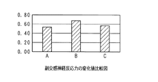
図10は実施の形態2に係る便座シートと比較例1、2便座シートの自律神経反応力変化値比較図である。自律神経反応力の変化値実験は便座シートに着座安静時から起立時直ぐとの間の自律神経反応力の変化値を測定する。下記の説明に示される図10〜13ではAを比較例1とし、Bを便座シート21とし、Cを比較例2とする。比較例1、便座シート21、比較例2の自律神経反応力の変化値は図10のように表される。便座シート21の自律神経反応力の変化値は比較例1、比較例2より小さい、即ち便座シート21の自律神経反応力の変化値は小さい。自律神経反応力の変化値が小さいのは、余計な力が入らずに楽に立ち上がることができると言える。自律神経反応力は例えば血圧又は脈拍などに基づいて求められる。
図11は実施の形態2に係る便座シートと比較例1、2便座シートの副交感神経反応力の変化値比較図である。副交感神経反応力の変化値実験は便座シートに起立安静時から着座時直ぐとの間の副交感神経反応力の変化値を測定する。比較例1、便座シート21、比較例2の副交感神経反応力の変化値は図11のように表される。便座シート21の副交感神経反応力の変化値は比較例1、比較例2より大きい、即ち便座シート21の副交感神経反応力の変化値が大きい。副交感神経反応力の変化値が大きいのは、立ち座りにストレスを感じずに行えて、着座時にリラックスできると言える。副交感神経反応力は例えば血圧又は脈拍などに基づいて求められる。
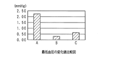
図12は実施の形態2に係る便座シートと比較例1、2便座シートの最高血圧の変化値比較図である。最高血圧の変化値実験は、便座シートに起立安静時から着座時直ぐとの間の最高血圧の変化値を測定する。比較例1、便座シート21、比較例2の最高血圧の変化値は図12のように表される。便座シート21の最高血圧の変化値は比較例1、比較例2より大きく、即ち最高血圧が大きく下がる。副交感神経が働いてリラックスした状態で座ると言える。
図13は実施の形態2に係る便座シートと比較例1、2便座シートの最低血圧の変化値比較図である。最低血圧の変化値実験は着座安静時から起立時直ぐとの間の最低血圧の変化値を測定する。比較例1、便座シート21、比較例2の最低血圧の変化値は図13のように表される。便座シート21の最低血圧の変化値は比較例1、比較例2より小さい、即ち便座シート21の最低血圧の変化値が小さい。最低血圧の変化値が小さいと言うのは、起立時のめまいやふらつきが少ない傾向になると言える。
In addition, we will conduct measurement experiments on changes in autonomic nervous function. The autonomic nerve responds to environmental stress while constantly changing the balance between the sympathetic nerve and the parasympathetic nerve. Functions that can appropriately respond to environmental stress are important. When function declines, blood pressure rises more than necessary. Measurement of changes in autonomic nervous function The experiment measures changes in autonomic nervous response, parasympathetic response, and systolic and diastolic blood pressure. In the experiment, the subject measures the values on the
Further, using the toilet seat seat of Comparative Example 1 and the toilet seat seat of Comparative Example 2, the same experimental equipment and method as those of the
FIG. 10 is a comparison diagram of the autonomic nerve reaction force change values of the toilet seat seat according to the second embodiment and the toilet seat seats of Comparative Examples 1 and 2. The change value of the autonomic nerve reaction force The experiment measures the change value of the autonomic nerve reaction force from the time of sitting on the toilet seat seat to the time of standing up. In FIGS. 10 to 13 shown in the following description, A is designated as Comparative Example 1, B is designated as the
FIG. 11 is a comparison diagram of changes in the parasympathetic nerve reaction force of the toilet seat seat according to the second embodiment and the toilet seat seats of Comparative Examples 1 and 2. The change value of the parasympathetic nerve reaction force The experiment measures the change value of the parasympathetic nerve reaction force from the time of standing on the toilet seat seat to the time of sitting. The change values of the parasympathetic nerve reaction force of Comparative Example 1, the
FIG. 12 is a comparison diagram of changes in systolic blood pressure of the toilet seat seat according to the second embodiment and the toilet seat seats of Comparative Examples 1 and 2. The change value experiment of systolic blood pressure measures the change value of systolic blood pressure from the time of standing rest to the time of sitting on the toilet seat. The changes in systolic blood pressure of Comparative Example 1, the
FIG. 13 is a comparison diagram of changes in the diastolic blood pressure of the toilet seat seat according to the second embodiment and the toilet seat seats of Comparative Examples 1 and 2. The change value experiment of the diastolic blood pressure measures the change value of the diastolic blood pressure from the time of sitting rest to the time of standing up. The changes in the diastolic blood pressure of Comparative Example 1, the
故に、便座シート21は便座に装着時に後側の厚い部分が他の部分より大きいな弾性力を生じることで、被験者の臀部に大きな反発力を与える。被験者は便座からの立ち上がりが容易になり、安定に立ち上がることができる。また、便座シート21はクッション体22の材質、形状により便座シート21にかかる体圧が吸収、分散され、被験者への負担を軽減できる。余計な力が入らずに楽に立ち上がることができ、リラックス状態で着座することができ、起立時のめまいやふらつきが少ない傾向になる効果がある。
Therefore, when the
今回開示した実施の形態は、全ての点で例示であって、制限的なものではないと考えられるべきである。各実施の形態にて記載されている技術的特徴は互いに組み合わせることができ、本発明の範囲は、特許請求の範囲内での全ての変更及び特許請求の範囲と均等の範囲が含まれることが意図される。 The embodiments disclosed this time should be considered to be exemplary in all respects and not restrictive. The technical features described in each embodiment may be combined with each other and the scope of the invention may include all modifications within the claims and the scope of the claims. Intended.
1、21 便座シート
2、22 クッション体
3、23 表面材
4 基材
40 粘着層
10 便器
11 便座
12 機能ボックス
1,21
Claims (5)
前記クッション体は、前記便座に着座する使用者の身体に接触する部分のうち、装着時に後側となる部分が他の部分より厚くしており、
前記クッション体は、前側となる部分から後側となる部分へ向かうに従って徐々に上昇傾斜し、
前記クッション体は、装着時に前記後側となる厚い部分が使用者の臀部下側に配置され、外周側から内周側に向けて非傾斜であり、体圧が吸収、分散され且つ反発力が生じるように、厚みを有し且つ前後に傾斜している便座シート。 In a toilet seat seat that is mounted so as to cover the seat portion of the toilet seat, has a curved shape corresponding to the seat portion, and includes a cushion body, a surface material, and a base material.
Of the parts of the cushion body that come into contact with the body of the user sitting on the toilet seat, the part that is on the rear side when worn is thicker than the other parts.
The cushion body gradually rises and tilts from the front side portion to the rear side portion.
In the cushion body, a thick portion on the rear side when worn is arranged on the lower side of the buttocks of the user , and is non-inclined from the outer peripheral side to the inner peripheral side, so that the body pressure is absorbed and dispersed, and the repulsive force is generated. occurs manner, toilet seat that inclined back and forth and having a thickness.
Priority Applications (1)
| Application Number | Priority Date | Filing Date | Title |
|---|---|---|---|
| JP2018215621A JP6832324B2 (en) | 2018-11-16 | 2018-11-16 | Toilet seat |
Applications Claiming Priority (1)
| Application Number | Priority Date | Filing Date | Title |
|---|---|---|---|
| JP2018215621A JP6832324B2 (en) | 2018-11-16 | 2018-11-16 | Toilet seat |
Publications (2)
| Publication Number | Publication Date |
|---|---|
| JP2020080997A JP2020080997A (en) | 2020-06-04 |
| JP6832324B2 true JP6832324B2 (en) | 2021-02-24 |
Family
ID=70904562
Family Applications (1)
| Application Number | Title | Priority Date | Filing Date |
|---|---|---|---|
| JP2018215621A Active JP6832324B2 (en) | 2018-11-16 | 2018-11-16 | Toilet seat |
Country Status (1)
| Country | Link |
|---|---|
| JP (1) | JP6832324B2 (en) |
Families Citing this family (1)
| Publication number | Priority date | Publication date | Assignee | Title |
|---|---|---|---|---|
| JP7432380B2 (en) * | 2020-02-03 | 2024-02-16 | 株式会社Lixil | toilet seat |
Family Cites Families (13)
| Publication number | Priority date | Publication date | Assignee | Title |
|---|---|---|---|---|
| JPS62150997U (en) * | 1986-03-19 | 1987-09-24 | ||
| JPS631498U (en) * | 1986-06-23 | 1988-01-07 | ||
| JP2518166Y2 (en) * | 1991-03-26 | 1996-11-20 | 章人 須田 | Toilet seat |
| JPH0614850A (en) * | 1991-03-29 | 1994-01-25 | Toyoda Gosei Co Ltd | Toilet seat |
| JP2000287884A (en) * | 1999-04-09 | 2000-10-17 | Sekisui Chem Co Ltd | Auxiliary toilet seat |
| JP2001161601A (en) * | 1999-12-14 | 2001-06-19 | Achilles Corp | Toilet seat cushion |
| JP3914394B2 (en) * | 2000-03-09 | 2007-05-16 | 太介 宮本 | Toilet seat cover |
| JP4530389B2 (en) * | 2001-02-08 | 2010-08-25 | 田中 多美江 | Toilet seat cover |
| JP2012130418A (en) * | 2010-12-20 | 2012-07-12 | Morito Co Ltd | Toilet seat sheet |
| JP5603822B2 (en) * | 2011-04-04 | 2014-10-08 | オカ株式会社 | Toilet seat |
| JP2014233460A (en) * | 2013-06-03 | 2014-12-15 | 株式会社リッチェル | Toilet seat |
| JP3197997U (en) * | 2015-03-31 | 2015-06-11 | 開智 張 | Toilet seat |
| JP3212226U (en) * | 2017-06-16 | 2017-08-31 | 一起 垣内 | Toilet seat |
-
2018
- 2018-11-16 JP JP2018215621A patent/JP6832324B2/en active Active
Also Published As
| Publication number | Publication date |
|---|---|
| JP2020080997A (en) | 2020-06-04 |
Similar Documents
| Publication | Publication Date | Title |
|---|---|---|
| US8047604B2 (en) | Bicycle saddle | |
| US3463547A (en) | Flexible chair seat | |
| US7024712B2 (en) | Posture correcting device | |
| JP2014046128A (en) | Chair and seat plate of the same | |
| JP6832324B2 (en) | Toilet seat | |
| US3848922A (en) | Wheelchair footplate cover cushion | |
| JP2014233460A (en) | Toilet seat | |
| US4574406A (en) | Tub comforter | |
| JP2002165676A (en) | Cushioning material and wheelchair equipped therewith | |
| JP2017136983A (en) | Vehicular seat | |
| US3672360A (en) | Spinal area back supporter and massaging device | |
| JP5335158B2 (en) | Exercise aid | |
| CN207076049U (en) | Multi-functional Yoga bustle | |
| JP6584206B2 (en) | Toilet device | |
| JP6236576B1 (en) | Defecation aid | |
| JPH042592Y2 (en) | ||
| US20180199720A1 (en) | Seat cushion | |
| JP6501668B2 (en) | Toilet bowl device | |
| EP1813514A2 (en) | Bicycle saddle | |
| JP6864981B2 (en) | Toilet bowl device | |
| JP6612950B1 (en) | Saddle and manufacturing method thereof | |
| JP3176134U (en) | Posture corrector | |
| JP2018187101A (en) | Seating device | |
| JP3129487U (en) | Handrail shelf unit for toilet | |
| JP2017176483A (en) | Posture holding device for floor seat |
Legal Events
| Date | Code | Title | Description |
|---|---|---|---|
| A621 | Written request for application examination |
Free format text: JAPANESE INTERMEDIATE CODE: A621 Effective date: 20181116 |
|
| A131 | Notification of reasons for refusal |
Free format text: JAPANESE INTERMEDIATE CODE: A131 Effective date: 20190903 |
|
| A521 | Request for written amendment filed |
Free format text: JAPANESE INTERMEDIATE CODE: A523 Effective date: 20191029 |
|
| A131 | Notification of reasons for refusal |
Free format text: JAPANESE INTERMEDIATE CODE: A131 Effective date: 20200225 |
|
| A521 | Request for written amendment filed |
Free format text: JAPANESE INTERMEDIATE CODE: A523 Effective date: 20200417 |
|
| A131 | Notification of reasons for refusal |
Free format text: JAPANESE INTERMEDIATE CODE: A131 Effective date: 20200825 |
|
| A521 | Request for written amendment filed |
Free format text: JAPANESE INTERMEDIATE CODE: A523 Effective date: 20201012 |
|
| TRDD | Decision of grant or rejection written | ||
| A01 | Written decision to grant a patent or to grant a registration (utility model) |
Free format text: JAPANESE INTERMEDIATE CODE: A01 Effective date: 20210119 |
|
| A61 | First payment of annual fees (during grant procedure) |
Free format text: JAPANESE INTERMEDIATE CODE: A61 Effective date: 20210201 |
|
| R150 | Certificate of patent or registration of utility model |
Ref document number: 6832324 Country of ref document: JP Free format text: JAPANESE INTERMEDIATE CODE: R150 |
|
| R250 | Receipt of annual fees |
Free format text: JAPANESE INTERMEDIATE CODE: R250 |