JP6832111B2 - Stent graft, stent graft set, and stent graft indwelling device - Google Patents
Stent graft, stent graft set, and stent graft indwelling device Download PDFInfo
- Publication number
- JP6832111B2 JP6832111B2 JP2016194754A JP2016194754A JP6832111B2 JP 6832111 B2 JP6832111 B2 JP 6832111B2 JP 2016194754 A JP2016194754 A JP 2016194754A JP 2016194754 A JP2016194754 A JP 2016194754A JP 6832111 B2 JP6832111 B2 JP 6832111B2
- Authority
- JP
- Japan
- Prior art keywords
- stent graft
- opening
- graft
- tubular
- main
- Prior art date
- Legal status (The legal status is an assumption and is not a legal conclusion. Google has not performed a legal analysis and makes no representation as to the accuracy of the status listed.)
- Active
Links
- 210000004204 blood vessel Anatomy 0.000 claims description 53
- 230000017531 blood circulation Effects 0.000 claims description 23
- 238000013459 approach Methods 0.000 claims description 5
- 230000002093 peripheral effect Effects 0.000 claims description 5
- 210000000709 aorta Anatomy 0.000 description 47
- 210000001367 artery Anatomy 0.000 description 46
- 208000007474 aortic aneurysm Diseases 0.000 description 27
- 238000010586 diagram Methods 0.000 description 14
- 239000000463 material Substances 0.000 description 11
- 238000000034 method Methods 0.000 description 11
- 239000008280 blood Substances 0.000 description 10
- 210000004369 blood Anatomy 0.000 description 10
- 239000011248 coating agent Substances 0.000 description 7
- 238000000576 coating method Methods 0.000 description 7
- 210000002376 aorta thoracic Anatomy 0.000 description 6
- 229920005989 resin Polymers 0.000 description 5
- 239000011347 resin Substances 0.000 description 5
- 229920003002 synthetic resin Polymers 0.000 description 4
- 239000000057 synthetic resin Substances 0.000 description 4
- 230000002792 vascular Effects 0.000 description 4
- 239000002473 artificial blood Substances 0.000 description 3
- 239000002184 metal Substances 0.000 description 3
- 229910052751 metal Inorganic materials 0.000 description 3
- -1 polytetrafluoroethylene Polymers 0.000 description 3
- 208000002251 Dissecting Aneurysm Diseases 0.000 description 2
- 206010002895 aortic dissection Diseases 0.000 description 2
- 230000000903 blocking effect Effects 0.000 description 2
- 229920001971 elastomer Polymers 0.000 description 2
- 239000000806 elastomer Substances 0.000 description 2
- 238000005516 engineering process Methods 0.000 description 2
- 210000003090 iliac artery Anatomy 0.000 description 2
- 238000012986 modification Methods 0.000 description 2
- 230000004048 modification Effects 0.000 description 2
- 229920006122 polyamide resin Polymers 0.000 description 2
- 229920001343 polytetrafluoroethylene Polymers 0.000 description 2
- 239000004810 polytetrafluoroethylene Substances 0.000 description 2
- 229920000915 polyvinyl chloride Polymers 0.000 description 2
- 239000004800 polyvinyl chloride Substances 0.000 description 2
- 239000011148 porous material Substances 0.000 description 2
- 238000001356 surgical procedure Methods 0.000 description 2
- 206010002329 Aneurysm Diseases 0.000 description 1
- 229910001111 Fine metal Inorganic materials 0.000 description 1
- 229910001069 Ti alloy Inorganic materials 0.000 description 1
- 238000004026 adhesive bonding Methods 0.000 description 1
- 229910045601 alloy Inorganic materials 0.000 description 1
- 239000000956 alloy Substances 0.000 description 1
- 210000000702 aorta abdominal Anatomy 0.000 description 1
- 238000005452 bending Methods 0.000 description 1
- 239000002131 composite material Substances 0.000 description 1
- 150000001875 compounds Chemical class 0.000 description 1
- 201000010099 disease Diseases 0.000 description 1
- 208000037265 diseases, disorders, signs and symptoms Diseases 0.000 description 1
- 230000000694 effects Effects 0.000 description 1
- KHYBPSFKEHXSLX-UHFFFAOYSA-N iminotitanium Chemical compound [Ti]=N KHYBPSFKEHXSLX-UHFFFAOYSA-N 0.000 description 1
- 230000001771 impaired effect Effects 0.000 description 1
- 238000002350 laparotomy Methods 0.000 description 1
- 210000005240 left ventricle Anatomy 0.000 description 1
- 229910001092 metal group alloy Inorganic materials 0.000 description 1
- 150000002739 metals Chemical class 0.000 description 1
- 229910001000 nickel titanium Inorganic materials 0.000 description 1
- 239000004033 plastic Substances 0.000 description 1
- 229920003023 plastic Polymers 0.000 description 1
- 229920001225 polyester resin Polymers 0.000 description 1
- 239000004645 polyester resin Substances 0.000 description 1
- 229920013716 polyethylene resin Polymers 0.000 description 1
- 229920000139 polyethylene terephthalate Polymers 0.000 description 1
- 239000005020 polyethylene terephthalate Substances 0.000 description 1
- 229920005749 polyurethane resin Polymers 0.000 description 1
- 238000002360 preparation method Methods 0.000 description 1
- 239000010935 stainless steel Substances 0.000 description 1
- 229910001220 stainless steel Inorganic materials 0.000 description 1
- 230000001629 suppression Effects 0.000 description 1
- 210000000689 upper leg Anatomy 0.000 description 1
Images


Description
本発明は、ステントグラフト、そのステントグラフトと他のステントグラフトとの組合せであるステントグラフトセット、及び、そのステントグラフトを血管内に留置するためのステントグラフト留置装置、に関する。 The present invention relates to a stent graft, a stent graft set which is a combination of the stent graft and another stent graft, and a stent graft indwelling device for indwelling the stent graft in a blood vessel.
従来から、大動脈に生じた大動脈瘤及び大動脈解離などの治療に用いられるステントグラフトが知られている。ステントグラフトは、一般に、血液流が通過可能な流路を画成する管形状を有しており、径方向内側への収縮及び径方向外側への拡張が可能な骨格部(ステント)と、その骨格部に沿って設けられた皮膜部(グラフト)と、を備えている。ステントグラフトは、骨格部が収縮した収縮状態にて患部(大動脈瘤等が生じている箇所)に運ばれた後、骨格部が拡張した拡張状態へと変形される。これにより、ステントグラフトは、血管を補強すると共に大動脈瘤等への血液流入を遮断し、大動脈瘤等の拡大(成長)を抑制するようになっている。 Conventionally, stent grafts used for the treatment of aortic aneurysm and aortic dissection occurring in the aorta have been known. A stent graft generally has a tubular shape that defines a flow path through which blood flow can pass, and has a skeleton (stent) capable of contracting inward in the radial direction and expanding in the outward direction in the radial direction, and a skeleton thereof. It is provided with a film portion (graft) provided along the portion. The stent graft is carried to the affected area (where the aortic aneurysm or the like is occurring) in a contracted state in which the skeleton is contracted, and then deformed into an expanded state in which the skeleton is expanded. As a result, the stent graft reinforces the blood vessels, blocks the inflow of blood into the aortic aneurysm and the like, and suppresses the expansion (growth) of the aortic aneurysm and the like.
例えば、従来のステントグラフトの一つ(以下「従来ステントグラフト」という。)は、主血管に生じた大動脈瘤等への血液流入を遮断しつつ、その主血管から分岐する分岐血管への血液流を維持するべく、主血管に留置するステントグラフトの側面に、分岐血管に向けて突出する円錐台形状の開口部(側面開口部)を備えている。従来ステントグラフトは、この側面開口部にも骨格部(例えば、側面開口部の基端から開口端に向けて延びる螺旋状のステント)を設けることにより、留置時に側面開口部を分岐血管に向けて押し出す(展開する)ようになっている(例えば、特許文献1を参照。)。 For example, one of the conventional stent grafts (hereinafter referred to as "conventional stent graft") maintains the blood flow from the main blood vessel to the bifurcated blood vessel while blocking the blood inflow to the aortic aneurysm or the like generated in the main blood vessel. Therefore, a conical trapezoidal opening (side opening) protruding toward the bifurcated blood vessel is provided on the side surface of the stent graft to be placed in the main blood vessel. Conventional stent grafts are provided with a skeleton (for example, a spiral stent extending from the base end of the side opening toward the opening) at the side opening to push the side opening toward a bifurcated blood vessel at the time of placement. (Expand) (see, for example, Patent Document 1).
上述したように、従来ステントグラフトは、留置時に円錐台形状の側面開口部を分岐血管に向けて押し出すことにより、側面開口部を分岐血管の血管口に挿入するようになっている。しかし、このような側面開口部の機能上、従来ステントグラフトは、側面開口部と分岐血管の血管口との間の位置ずれが出来る限り小さくなるよう、高い位置精度にて留置される必要がある。換言すると、従来ステントグラフトは、留置時に位置精度が不十分である場合、側面開口部が主血管の内壁等に接触(干渉)して分岐血管の血管口に十分に挿入されない(側面開口部が十分に開かない)可能性がある。 As described above, the conventional stent graft is adapted to insert the lateral opening into the vascular opening of the bifurcated blood vessel by pushing the truncated cone-shaped lateral opening toward the bifurcated blood vessel at the time of indwelling. However, due to the function of such a lateral opening, the conventional stent graft needs to be placed with high positional accuracy so that the positional deviation between the lateral opening and the vascular opening of the bifurcated vessel is as small as possible. In other words, in the conventional stent graft, when the position accuracy is insufficient at the time of placement, the lateral opening contacts (interferes) with the inner wall of the main blood vessel and is not sufficiently inserted into the vascular opening of the bifurcated blood vessel (the lateral opening is sufficient). May not open).
一方、通常、ステントグラフトの留置は、X線透視装置による透視画像(二次元の平面画像)を拠り所として行われる。そのため、従来ステントグラフトの側面開口部が分岐血管に対して十分に合致するように(特に、従来ステントグラフトの軸線周りの回転方向において十分に合致するように)従来ステントグラフトを配置することは、一般に困難であり、そのような配置のためには非常に高度な技術が求められることになる。 On the other hand, the placement of the stent graft is usually performed based on a fluoroscopic image (two-dimensional plane image) obtained by an X-ray fluoroscope. Therefore, it is generally difficult to place the conventional stent graft so that the lateral openings of the conventional stent graft are sufficiently aligned with the bifurcated blood vessels (particularly so that they are sufficiently aligned in the rotational direction around the axis of the conventional stent graft). Yes, very advanced technology will be required for such an arrangement.
しかし、ステントグラフトの留置を出来る限り容易にする観点からは、分岐血管と、分岐血管に向けて突出する円錐台形状の側面開口部と、の位置合わせの精度(留置時の位置精度)が仮に不十分であったとしても、ステントグラフトとしての機能が損なわれることがないように、従来ステントグラフトが構成されていることが望ましい。 However, from the viewpoint of facilitating the placement of the stent graft as much as possible, the accuracy of alignment (position accuracy at the time of placement) between the branched blood vessel and the truncated cone-shaped side opening protruding toward the branched blood vessel is tentatively inadequate. Even if it is sufficient, it is desirable that the conventional stent graft is configured so that the function as the stent graft is not impaired.
本発明は、上述した事情に鑑みてなされたものであり、その目的は、留置時の位置精度が仮に不十分であったとしてもステントグラフトとしての機能を十分に発揮することが可能なステントグラフト、そのステントグラフトと他のステントグラフトとの組合せであるステントグラフトセット、及び、そのステントグラフトを血管内に留置するためのステントグラフト留置装置、を提供することにある。 The present invention has been made in view of the above circumstances, and an object of the present invention is a stent graft capable of sufficiently exerting a function as a stent graft even if the position accuracy at the time of placement is insufficient. It is an object of the present invention to provide a stent graft set which is a combination of a stent graft and another stent graft, and a stent graft indwelling device for indwelling the stent graft in a blood vessel.
前述した目的を達成するために、本発明に係る「ステントグラフト」は、下記(1)〜(3)を特徴としている。
(1)
血液流が通過可能な流路を画成する管状のステントグラフトであって、
径方向内側への収縮及び径方向外側への拡張が可能な骨格部と、
前記骨格部に沿って設けられた皮膜部と、を備え、
前記骨格部が収縮した収縮状態から、前記骨格部が拡張して前記皮膜部によって前記流路が画成された拡張状態へ、変形可能であり、
前記拡張状態において、外周面の一部が径方向内側に窪み、平面状の底面を有する凹部と、前記凹部の前記底面の所定位置から径方向外側に向けて延びる筒状に形成され、前記血液流が通過可能な筒状開口部と、を有し、
前記筒状開口部が、
前記流路から分流して当該筒状開口部を通過する血液流によって当該筒状開口部の開口向きを変更可能な柔軟性を有する、
ステントグラフトであること。
(2)
上記(1)に記載のステントグラフトにおいて、
前記筒状開口部の全体が、
前記拡張状態において、前記凹部によって画成される窪み空間の内側に存在する、
ステントグラフトであること。
(3)
上記(1)又は上記(2)に記載のステントグラフトにおいて、
前記骨格部が、
前記筒状開口部と前記凹部との接続箇所の近傍に存在しない、
ステントグラフトであること。
In order to achieve the above-mentioned object, the "stent graft" according to the present invention is characterized by the following (1) to (3).
(1)
A tubular stent graft that defines a flow path through which blood flows.
A skeleton that can contract inward in the radial direction and expand outward in the radial direction,
A film portion provided along the skeleton portion is provided.
It is possible to deform from the contracted state in which the skeleton portion is contracted to the expanded state in which the skeleton portion is expanded and the flow path is defined by the film portion.
Wherein in the expanded state, see recessed portion is radially inward of the outer peripheral surface is formed a recess having a planar bottom surface, a cylindrical shape extending radially outward from a predetermined position of the bottom surface of the recess, the blood flow is closed and the cylindrical opening capable of passing, and
The tubular opening
To have the opening facing the changeable flexibility of the cylindrical opening by the blood flow through the cylindrical opening diverted from the flow channel,
Must be a stent graft.
( 2 )
In the stent graft described in (1) above
The entire tubular opening
In the expanded state, it exists inside the recessed space defined by the recesses.
Must be a stent graft.
( 3 )
In the stent graft according to (1) or (2) above.
The skeleton
It does not exist near the connection point between the tubular opening and the recess.
Must be a stent graft.
上記(1)の構成のステントグラフトによれば、ステントグラフトの外周面に径方向内側に窪んだ凹部が形成されており、その凹部内に径方向外側に向けて延びる筒状に形成され、血液流が通過可能な筒状開口部が設けられている。そのため、主血管と分岐血管との分岐位置に本構成のステントグラフトが留置される際、仮に筒状開口部が分岐血管に対して十分に合致していなくても、凹部内にて筒状開口部が開く(径方向外側に延びる)ことができる分、従来ステントグラフトに比べて位置ずれに対する許容度が大きいことになる。即ち、本構成のステントグラフトは、従来ステントグラフトに比べ、ステントグラフトとしての機能(例えば、分岐血管への血流確保)を維持しながら、留置時に筒状開口部が開き易い。 According to the stent graft having the configuration of (1) above, a concave portion recessed inward in the radial direction is formed on the outer peripheral surface of the stent graft, and a tubular shape extending outward in the radial direction is formed in the concave portion to allow blood flow. It is provided with a passable tubular opening. Therefore, when the stent graft of this configuration is placed at the bifurcation position between the main blood vessel and the bifurcated blood vessel, even if the tubular opening does not sufficiently match the bifurcated blood vessel, the tubular opening is in the recess. Can be opened (extended outward in the radial direction), so that the tolerance for misalignment is larger than that of the conventional stent graft. That is, the stent graft having this configuration is more likely to open a tubular opening during indwelling while maintaining the function as a stent graft (for example, ensuring blood flow to a bifurcated blood vessel) as compared with a conventional stent graft.
したがって、本構成のステントグラフトは、従来ステントグラフトに比べ、留置時の位置精度が仮に不十分であったとしてもステントグラフトとしての機能を十分に発揮することが可能である。 Therefore, the stent graft having this configuration can sufficiently exert the function as a stent graft as compared with the conventional stent graft, even if the position accuracy at the time of placement is insufficient.
なお、上記構成のステントグラフトを用いれば、主血管と分岐血管との分岐位置の近傍に生じた大動脈瘤等の治療も可能である。具体的には、主血管にステントグラフトを留置した後、ステントグラフトの筒状開口部と、分岐血管に留置された別のステントグラフト(いわゆるブランチ・ステントグラフト)と、を接続すれば、分岐位置の近傍に生じた大動脈瘤等への血液流入を遮断できる。上記構成のステントグラフトは、上述したように筒状開口部が開き易いため、従来ステントグラフトに比べ、別のステントグラフトと容易に接続できる。 By using the stent graft having the above configuration, it is possible to treat an aortic aneurysm or the like generated in the vicinity of the bifurcation position between the main blood vessel and the bifurcated blood vessel. Specifically, after placing a stent graft in the main blood vessel, if the tubular opening of the stent graft and another stent graft placed in the bifurcated blood vessel (so-called branch stent graft) are connected, it will occur near the bifurcation position. It can block the inflow of blood into aortic aneurysms and the like. Since the tubular opening of the stent graft having the above configuration is easy to open as described above, it can be easily connected to another stent graft as compared with the conventional stent graft.
更に、上記(1)の構成のステントグラフトによれば、筒状開口部は、主血管(流路)から分流した血液流によって筒状開口部の開口向きが変形可能な程度の柔軟性(フレキシビリティ)を有する。そのため、仮に筒状開口部が分岐血管に対して十分に合致していなくても、主血管から分岐血管に向かう血液流により、筒状開口部が分岐血管に向けて自然に案内されることになる。よって、筒状開口部の開き易さが向上する。更に、筒状開口部がこのような柔軟性を有するため、別のステントグラフト(ブランチ・ステントグラフト)との接続の際、両者の密着性も向上することになる。 Furthermore, according to the stent graft of the above configuration (1), the tubular opening, the main vessel degree opening direction is deformable tubular opening by the blood flow diverted from (channel) Flexibility (Flexibility ). Therefore, even if the tubular opening does not sufficiently match the bifurcated blood vessel, the blood flow from the main blood vessel to the bifurcated blood vessel naturally guides the tubular opening toward the bifurcated blood vessel. Become. Therefore, the ease of opening the tubular opening is improved. Further, since the tubular opening has such flexibility, the adhesion between the two is improved when the tubular opening is connected to another stent graft (branch stent graft).
なお、筒状開口部は、ステントグラフトを構成する皮膜部によって(皮膜部を延ばすように)構成されてもよく、皮膜部とは別の独立した部材を凹部に接続する(例えば、接着する)ことによって構成されてもよい。更に、筒状開口部は、上述した骨格部(ステント)とは別の部材として、開口端(ステントグラフトの径方向外側に向かう最端部)の閉塞等を防ぐべく、開口端に沿って設けられたリング状の保持具を有してもよい。同様に、筒状開口部は、骨格部(ステント)とは別の部材として、基端(筒状開口部と凹部との接続箇所)の閉塞等を防ぐべく、基端に沿って設けられたリング状の保持具を有してもよい。 The tubular opening may be formed by a coating portion constituting the stent graft (so as to extend the coating portion), and an independent member other than the coating portion may be connected (for example, adhered) to the recess. It may be composed of. Further, the tubular opening is provided along the opening end as a member separate from the skeleton portion (stent) described above in order to prevent obstruction of the opening end (the outermost end portion in the radial direction of the stent graft). It may have a ring-shaped holder. Similarly, the tubular opening is provided along the proximal end as a member separate from the skeleton portion (stent) in order to prevent obstruction of the proximal end (the connection point between the tubular opening and the recess). It may have a ring-shaped retainer.
上記(2)の構成のステントグラフトによれば、筒状開口部の全体が凹部による窪み空間の内側に存在する。換言すると、凹部と筒状開口部との接続箇所(筒状開口部の基端)から筒状開口部の開口端までの長さ(即ち、筒状開口部の高さ)よりも、凹部の深さが大きい。そのため、仮に筒状開口部が分岐血管に対して十分に合致していなくても、筒状開口部の開口端が主血管の内壁等に接触(干渉)することがない。よって、筒状開口部の開き易さが更に向上する。 According to the stent graft having the above configuration (2 ), the entire tubular opening exists inside the recessed space due to the recess. In other words, the length of the recess from the connection point between the recess and the tubular opening (the base end of the tubular opening) to the opening end of the tubular opening (ie, the height of the tubular opening) The depth is large. Therefore, even if the tubular opening does not sufficiently match the bifurcated blood vessel, the opening end of the tubular opening does not come into contact (interfere) with the inner wall of the main blood vessel or the like. Therefore, the ease of opening the tubular opening is further improved.
ところで、上記「窪み空間」とは、凹部を画成するステントグラフトの表面と、凹部が存在しないと仮定した場合におけるステントグラフトの表面(仮想的な表面)と、に挟まれる空間を表す。別の言い方をすると、上記「窪み空間」とは、ステントグラフトを血管内に留置した際、凹部を画成するステントグラフトの表面と、血管の内壁面と、に挟まれる空間を表す。 By the way, the above-mentioned "recessed space" represents a space sandwiched between the surface of the stent graft that defines the recess and the surface (virtual surface) of the stent graft when it is assumed that the recess does not exist. In other words, the above-mentioned "recessed space" represents a space sandwiched between the surface of the stent graft that defines the recess and the inner wall surface of the blood vessel when the stent graft is placed in the blood vessel.
上記(3)の構成のステントグラフトによれば、筒状開口部と凹部との接続箇所(筒状開口部の基端)の近傍に骨格部が存在しない。そのため、筒状開口部の開口向きの自由度(上述した筒状開口部の柔軟性。フレキシビリティ)が更に向上する。よって、筒状開口部の開き易さが更に向上する。 According to the stent graft having the above configuration (3 ), there is no skeleton portion in the vicinity of the connection point (base end of the tubular opening) between the tubular opening and the recess. Therefore, the degree of freedom in the opening direction of the tubular opening (the flexibility of the tubular opening described above, flexibility) is further improved. Therefore, the ease of opening the tubular opening is further improved.
ところで、上記「接続箇所の近傍」とは、例えば、主血管を通過する血液流による径方向外側に向けた圧力に抗して、凹部(窪み空間)を維持可能な程度の範囲を表す。例えば、凹部の周辺(凹部の外側)の骨格部によって凹部(窪み空間)を維持可能であれば、凹部の全体に骨格部が存在しなくてもよい。 By the way, the above-mentioned "near the connection point" represents, for example, a range in which a recess (recessed space) can be maintained against a pressure toward the outside in the radial direction due to a blood flow passing through a main blood vessel. For example, if the recess (recess space) can be maintained by the skeleton portion around the recess (outside the recess), the skeleton portion may not be present in the entire recess.
更に、前述した目的を達成するために、本発明に係る「ステントグラフトセット」は、下記(4)及び(5)を特徴としている。
(4)
上記(1)〜上記(3)の何れか一つに記載のステントグラフトである第1ステントグラフトと、
前記第1ステントグラフトが有する前記筒状開口部へ接続可能な管状の第2ステントグラフトと、を備えた、
ステントグラフトセットであること。
(5)
上記(4)に記載のステントグラフトセットにおいて、
前記筒状開口部が、
該筒状開口部と前記凹部との接続箇所から離れるにつれて開口面積が小さくなる縮径形状を有し、
前記第2ステントグラフトが、
開口端の近傍において、前記開口端に近付くにつれて開口面積が大きくなる拡径形状を有し、
前記第1ステントグラフトの前記筒状開口部と、前記第2ステントグラフトの前記開口端の近傍と、が互いに密着する、
ステントグラフトセットであること。
Further, in order to achieve the above-mentioned object, the "stent graft set" according to the present invention is characterized by the following (4 ) and ( 5).
( 4 )
The first stent graft, which is the stent graft according to any one of the above (1) to ( 3),
A tubular second stent graft that can be connected to the tubular opening of the first stent graft.
Must be a stent graft set.
( 5 )
In the stent graft set described in (4) above,
The tubular opening
It has a reduced diameter shape in which the opening area becomes smaller as the distance from the connection point between the tubular opening and the recess is increased.
The second stent graft
In the vicinity of the opening end, it has an enlarged diameter shape in which the opening area increases as it approaches the opening end.
The tubular opening of the first stent graft and the vicinity of the opening end of the second stent graft are in close contact with each other.
Must be a stent graft set.
上記(4)の構成のステントグラフトセットによれば、上記(1)〜(3)の特徴を有する第1ステントグラフト(メイン・ステントグラフト)の筒状開口部に、第2ステントグラフト(ブランチ・ステントグラフト)を接続することにより、主血管と分岐血管との分岐位置の近傍に生じた大動脈瘤等への血液流入を遮断し、そのような大動脈瘤等の治療が可能となる。第1ステントグラフトは、上記(1)〜(3)に記載のように筒状開口部が開き易いため、従来ステントグラフトに比べ、第2ステントグラフトと容易に接続である。 According to the stent graft set having the configuration of ( 4 ) above, the second stent graft (branch stent graft) is connected to the tubular opening of the first stent graft (main stent graft) having the characteristics of (1) to (3) above. By doing so, blood inflow to an aortic aneurysm or the like generated in the vicinity of the bifurcation position between the main blood vessel and the bifurcated blood vessel is blocked, and such an aortic aneurysm or the like can be treated. As described in (1) to ( 3 ) above, the first stent graft is easily connected to the second stent graft as compared with the conventional stent graft because the tubular opening is easily opened.
上記(5)の構成のステントグラフトセットによれば、第1ステントグラフトの筒状開口部の縮径部分と、第2ステントグラフトの開口端の近傍の拡径部分と、が互いに密着する。これにより、そのような縮径部分および拡径部分が存在しない場合に比べ、両者の接触面積が増大し、両者の間の液密性を向上できる。よって、第1ステントグラフトと第2ステントグラフトとの間からの血液の漏れ(いわゆるエンドリーク)を抑制できる。 According to the stent graft set having the above configuration (5 ), the reduced diameter portion of the tubular opening of the first stent graft and the enlarged diameter portion near the opening end of the second stent graft are in close contact with each other. As a result, the contact area between the two can be increased and the liquidtightness between the two can be improved as compared with the case where such a reduced diameter portion and an enlarged diameter portion do not exist. Therefore, it is possible to suppress blood leakage (so-called end leak) between the first stent graft and the second stent graft.
ところで、上記「開口端の近傍」とは、例えば、上述した液密性(エンドリークの抑制)を実現可能な程度の範囲を表す。 By the way, the above-mentioned "near the opening end" represents, for example, a range to which the above-mentioned liquidtightness (suppression of end leakage) can be realized.
更に、前述した目的を達成するために、本発明に係る「ステントグラフト留置装置」は、下記(6)を特徴としている。
(6)
血管内にステントグラフトを留置するためのステントグラフト留置装置であって、
上記(1)〜上記(3)の何れか一つに記載のステントグラフトと、
前記ステントグラフトが前記収縮状態にて収容された収容具と、
前記収容具から前記ステントグラフトを放出して前記拡張状態に変形させる操作具と、
を備えた、
ステントグラフト留置装置であること。
Further, in order to achieve the above-mentioned object, the "stent graft indwelling device" according to the present invention is characterized by the following (6).
( 6 )
A stent graft indwelling device for indwelling a stent graft in a blood vessel.
The stent graft according to any one of (1) to ( 3) above,
A container in which the stent graft is housed in the contracted state and
An operating tool that releases the stent graft from the container and transforms it into the expanded state.
With,
Must be a stent graft placement device.
上記(6)の構成のステントグラフト留置装置によれば、上記(1)〜(3)の特徴を有するステントグラフトを血管内に留置するための器具一式を提供できる。 According to the stent graft indwelling device having the configuration of (6 ) above, it is possible to provide a set of instruments for indwelling a stent graft having the characteristics of (1) to (3) above in a blood vessel.
本発明によれば、留置時の位置精度が仮に不十分であったとしてもステントグラフトとしての機能を十分に発揮することが可能なステントグラフト、そのステントグラフトと他のステントグラフトとの組合せであるステントグラフトセット、及び、そのステントグラフトを血管内に留置するためのステントグラフト留置装置、を提供できる。 According to the present invention, a stent graft capable of sufficiently exerting a function as a stent graft even if the position accuracy at the time of placement is insufficient, a stent graft set which is a combination of the stent graft and another stent graft, and a stent graft set. , A stent graft indwelling device for indwelling the stent graft in a blood vessel can be provided.
以上、本発明について簡潔に説明した。更に、以下に説明される発明を実施するための形態(以下「実施形態」という。)を添付の図面を参照して通読することにより、本発明の詳細は更に明確化されるであろう。 The present invention has been briefly described above. Further, the details of the present invention will be further clarified by reading through the embodiments for carrying out the invention described below (hereinafter referred to as "embodiments") with reference to the accompanying drawings.
<大動脈とステントグラフト>
以下、本発明の実施形態を説明するための準備として、先ず、図1を参照しながら、人体の大動脈の構造、及び、大動脈瘤等の治療に使用されるステントグラフトについて簡単に説明する。
<Aorta and stent graft>
Hereinafter, as a preparation for explaining the embodiment of the present invention, first, with reference to FIG. 1, the structure of the aorta of the human body and the stent graft used for the treatment of aortic aneurysm and the like will be briefly described.
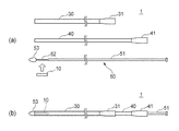
図1(a)に示すように、人体の大動脈は、心臓の左心室から上行して弓状に屈曲した後、下行して腹部大動脈の分岐部で総腸骨動脈に分岐されるまでの動脈であって、全身への血液循環の大元となる動脈である。この大動脈を構成する血管壁の一部がこぶ状に膨らんだ状態を「大動脈瘤」という。一方、この大動脈を構成する血管壁の内膜に生じた裂孔等を通じて流出した血液によって中膜に剥がれ(解離)が生じた状態を「大動脈解離」という。これら大動脈瘤等は、大動脈の様々な部位に発生し得るものである。大動脈瘤等は、放置すると死に至る可能性もある重篤な疾患である。 As shown in FIG. 1 (a), the aorta of the human body is an artery that ascends from the left ventricle of the heart, bends in an arch shape, and then descends to the common iliac artery at the bifurcation of the abdominal aorta. It is an artery that is the source of blood circulation to the whole body. A state in which a part of the blood vessel wall constituting the aorta is swollen like a hump is called an "aortic aneurysm". On the other hand, a state in which the media is peeled off (dissociated) by blood flowing out through a fissure or the like formed in the intima of the blood vessel wall constituting the aorta is called "aortic dissection". These aortic aneurysms and the like can occur in various parts of the aorta. Aortic aneurysm and the like are serious diseases that can lead to death if left untreated.
大動脈瘤等の外科的治療法としては、大動脈瘤等が形成されている患部の血管ごと人工血管に置き換える、いわゆる「人工血管置換術」が良く知られている。これに対し、近年、「ステントグラフト内挿術」などと呼ばれる手法が注目されている。この手法は、シース内部に縮径保持されたステントグラフトを備えるステントグラフト留置装置を用いる方法である。具体的には、この方法は、例えば、鼠径部と呼ばれる太股の付け根部分を小さく切開してシースを大動脈内に挿入し、患部においてシースの先端からステントグラフトを露出・展開させてステントグラフトを患部に留置することにより、大動脈瘤等の破裂を防止する方法である。ステントグラフト内挿術は、人工血管置換術と比べ、開胸又は開腹手術を行わなくてもよい低侵襲な治療方法である。 As a surgical treatment method for aortic aneurysm and the like, so-called "artificial blood vessel replacement" is well known, in which the blood vessels in the affected area where the aortic aneurysm or the like is formed are replaced with artificial blood vessels. On the other hand, in recent years, a method called "stent graft interpolation" or the like has attracted attention. This method is a method using a stent graft indwelling device including a stent graft whose diameter is maintained inside the sheath. Specifically, in this method, for example, a small incision is made in the base of the thigh called the inguinal region, a sheath is inserted into the aorta, and the stent graft is exposed and deployed from the tip of the sheath in the affected area, and the stent graft is placed in the affected area. This is a method of preventing rupture of an aortic aneurysm or the like. Stent graft interpolation is a minimally invasive treatment method that does not require thoracotomy or laparotomy as compared with artificial blood vessel replacement surgery.
図1(b)に示すように、大動脈のうち、特に胸部大動脈では、大動脈(主血管)から分岐する3つの分岐動脈(分岐血管)が存在する。本発明の実施形態に係るステントグラフトは、特に、大動脈と分岐動脈との分岐位置の近傍の大動脈に生じた大動脈瘤等の治療に用い得る。なお、本発明の実施形態に係るステントグラフトは、他の部位に生じた大動脈瘤等の治療にも用い得る。 As shown in FIG. 1 (b), among the aortas, especially in the thoracic aorta, there are three bifurcated arteries (branched blood vessels) branching from the aorta (main blood vessel). The stent graft according to the embodiment of the present invention can be used particularly for the treatment of an aortic aneurysm or the like occurring in the aorta in the vicinity of the bifurcation position between the aorta and the bifurcated artery. The stent graft according to the embodiment of the present invention can also be used for the treatment of aortic aneurysms and the like generated at other sites.
<全体構成>
以下、図面を参照しながら、本発明の実施形態に係るステントグラフト10(メイン・ステントグラフト)、ステントグラフトセット、及び、ステントグラフト留置装置1について、図2〜図7を参照しながら説明する。
<Overall configuration>
Hereinafter, the stent graft 10 (main stent graft), the stent graft set, and the stent graft
なお、以下、便宜上、メイン・ステントグラフトを単に「メイングラフト」と称呼し、ブランチ・ステントグラフトを単に「ブランチグラフト」と称呼する。 Hereinafter, for convenience, the main stent graft will be simply referred to as a "main graft", and the branch stent graft will be simply referred to as a "branch graft".
図2(a)に示すように、本発明の実施形態に係るステントグラフトセットは、メイングラフト10及びブランチグラフト20を有する。メイングラフト10は、大動脈の患部(大動脈瘤等が生じている箇所)に留置され、ブランチグラフト20は、患部近傍の大動脈から分岐する分岐動脈に留置される。
As shown in FIG. 2A, the stent graft set according to the embodiment of the present invention has a
<メイングラフト>
先ず、メイングラフト10について説明する。図2(a)〜図2(c)に示すように、メイングラフト10は、血液流が通過可能な管状流路を画成する管形状を有し、骨格部11(ステント)及び皮膜部12(グラフト)を有する。本例では、メイングラフト10は、直線状の管形状を有している。しかし、メイングラフト10の形状は必ずしも直線状に限定されず、必要に応じて(例えば、患者の大動脈弓の形状に対応した形状に)湾曲した管形状を有してもよい(後述する図8も参照)。メイングラフト10は、留置の前から予め留置箇所を想定した湾曲形状を有していてもよく、留置の後に血管形状に沿った湾曲形状を有することになってもよい。
<Main graft>
First, the
骨格部11は、金属細線がジグザグ状に折り返されると共に管形状に成形された自己拡張型の金網状に構成され、径方向内側に収縮した収縮状態から、径方向外側に拡張して管状流路が画成された拡張状態へ、変形可能となっている。骨格部11を構成する材料として、例えば、ステンレス鋼、Ni−Ti合金、チタン合金などに代表される公知の金属又は金属合金が挙げられる。
The
皮膜部12は、骨格部11に沿って骨格部11を覆うように骨格部11に固定されており、上述した管状流路を画成している。皮膜部12は、骨格部11を外周から覆っても内周から覆ってもよく、骨格部11を挟み込むように覆ってもよい。皮膜部12の材料として、例えば、PTFE(ポリテトラフルオロエチレン)等のフッ素樹脂、及び、ポリエチレンテレフタレート等のポリエステル樹脂などが挙げられる。
The
皮膜部12は、上述した拡張状態において、外周面の一部が径方向内側に窪んだ凹部13と、凹部13内の所定位置から径方向外側に向けて延びる筒状開口部14と、を有する。筒状開口部14は、ブランチグラフト20の後述する接続側端部23が接続される部分である(後述する図7を参照)。
In the expanded state described above, the
以下、説明の便宜上、図2(c)に示すように、凹部13を画成するメイングラフト10の表面13aと、凹部13が存在しない仮定した場合におけるメイングラフト10の表面13b(図2(c)に破線にて示す仮想的な表面)と、に挟まれる空間を「窪み空間15」と呼ぶ。換言すると、窪み空間15とは、凹部13を画成するメイングラフト10の表面と、メイングラフト10が大動脈内に留置された場合における大動脈の内壁面と、に挟まれる空間を指す。
Hereinafter, for convenience of explanation, as shown in FIG. 2C, the
本例では、特に図2(a)及び図2(c)に示すように、凹部13は、平面状の底面を有し、その底面の中央位置から筒状開口部14が径方向外側に向けて延びている。筒状開口部14は、筒状開口部14と凹部13の底面との接続箇所から離れるにつれて開口面積が小さくなる縮径形状を有する。更に、筒状開口部14の全体が、窪み空間15の内側に存在する。換言すると、凹部13と筒状開口部14との接続箇所(筒状開口部14の基端)から筒状開口部14の開口端までの長さ(筒状開口部14の高さ)よりも、凹部13の深さが大きい。
In this example, as shown in FIGS. 2A and 2C, the
凹部13の底面、及び筒状開口部14には、骨格部11が存在しない。更に、筒状開口部14は、皮膜部12と同様の材料によって形成されている。その結果、筒状開口部14は、大動脈から分岐動脈へ分岐した血液流によって開口向きが変形可能な程度の柔軟性(フレキシビリティ)を有する。
The
なお、筒状開口部14は、皮膜部12によって(皮膜部12を延ばすように)構成されてもよく、皮膜部12とは別の独立した部材として形成され、その部材を凹部13に設けた孔に接続する(例えば、接着する)ことによって構成されてもよい。
The
<ブランチグラフト>
次いで、ブランチグラフト20について説明する。図2(a)に示すように、ブランチグラフト20も、メイングラフト10と同様、血液流が通過可能な管状流路を画成する管形状を有し、自己拡張型の骨格部21と、皮膜部22と、を有する。骨格部21及び皮膜部22の構成は、メイングラフト10の骨格部11及び皮膜部12と同様であるため、これらの詳細な説明を省略する。
<Branch graft>
Next, the
ブランチグラフト20における筒状開口部14と接続される側の端部23(接続側端部)は、開口端に近付くにつれて開口面積が大きくなる拡径形状を有する。後述するように、このような拡径形状を有するブランチグラフト20の接続側端部23の外表面と、上述した縮径形状を有するメイングラフト10の筒状開口部14の内表面と、が密着するように、メイングラフト10とブランチグラフト20とが接続される(後述する図7を参照)。
The end portion 23 (connecting side end portion) of the
<ステントグラフト留置装置>
次いで、メイングラフト10(及びブランチグラフト20)を血管内の所定位置に留置するためのステントグラフト留置装置1について、図3を参照しながら説明する。以下、図3において、右側を基端側、左側を先端側と呼ぶ。
<Stent graft indwelling device>
Next, a stent graft
図3(a)及び図3(b)に示すように、ステントグラフト留置装置1は、管状の第1シース30と、第1シース30の内側に配置され、第1シース30の内側を第1シース30の軸方向(長手方向)に沿って進退可能に構成された管状の第2シース40と、第2シース40の内側に配置され、第2シース40の内側を第2シース40の軸方向(長手方向)に沿って進退可能に構成された棒状のロッド部材50と、を備える。
As shown in FIGS. 3 (a) and 3 (b), the stent graft
第1シース30及び第2シース40は、ともに可撓性を有する材料で形成されている。可撓性材料として、例えば、フッ素樹脂、ポリアミド系樹脂、ポリエチレン系樹脂、及び、ポリ塩化ビニル系樹脂等から選択された生体適合性を有する合成樹脂(エラストマー)、これら樹脂に他の材料が混合された樹脂コンパウンド、これらの合成樹脂による多層構造体、並びに、これら合成樹脂と金属線との複合体などが挙げられる。
Both the
第1シース30の基端側には、基端に近付くにつれて開口面積が大きくなる拡径形状を有する第1シース基部31が設けられている。同様に、第2シース40の基端側には、基端に近付くにつれて開口面積が大きくなる拡径形状を有する第2シース基部41が設けられている。
On the base end side of the
図3(a)に示すように、ロッド部材50は、ロッド本体部51と、収縮状態にあるメイングラフト10を保持する保持部52と、ロッド部材50の先端側の端部に設けられた先端チップ53と、を有する。保持部52は、メイングラフト10(又はブランチグラフト20)の厚さ分だけロッド本体部51よりも直径が小さい。したがって、保持部52に保持された収縮状態にあるメイングラフト10(又はブランチグラフト20)の外径は、ロッド本体部51の外径と略等しい。図3(b)から理解できるように、先端チップ53の最大径は、第1シース30の外径と略等しい。
As shown in FIG. 3A, the
ロッド本体部51及び保持部52を構成する材料として、例えば、樹脂(プラスチック、エラストマー)及び金属など、適度な硬度及び柔軟性を有する種々の材料が挙げられる。先端チップ53を構成する材料として、例えば、ポリアミド系樹脂、ポリウレタン系樹脂およびポリ塩化ビニル系樹脂等から構成された合成樹脂(エラストマー)などの、適度な硬度及び柔軟性を有する種々の材料が挙げられる。
Examples of the material constituting the
なお、図示による説明は省略するが、ロッド本体部51、保持部52及び先端チップ53には、例えば、ガイドワイヤを挿通させるためのガイドワイヤ用の細孔、及び、収縮状態のステントグラフト10(及びブランチグラフト20)を患部で拡張させるためのトリガワイヤを挿通させるためのトリガワイヤ用の細孔などが、ロッド部材50の軸方向(ロッド部材50の長手方向)に沿って形成されている。
Although not shown, the
更に、詳細な説明は省略するが、先端チップ53には、上記トリガワイヤを係止するための係止溝(図示省略)が設けられている。このようなトリガワイヤ及び先端チップを用いて収縮状態のステントグラフト10(又はブランチグラフト20)を患部において拡張させる方法については、公知の方法を用いることができる。
Further, although detailed description is omitted, the
図3(b)に示すように、メイングラフト10が、第2シース40の内側にてロッド部材の50の保持部52に保持された状態(即ち、収縮状態)では、図4に示すように、筒状開口部14が、筒状開口部14と凹部13の底面との接続部分(基端)から徐々に径方向内側に畳まれている。これにより、筒状開口部14同士の重なりが生じ難い。よって、筒状開口部14の畳み込みが容易になる。これは、筒状開口部14が上述した縮径形状を有することに因る。
As shown in FIG. 3B, in a state where the
次いで、図3(b)に示すステントグラフト留置装置1を用いて、メイングラフト10を大動脈内の患部に留置する際の手順について、図5を参照しながら説明する。図5では、胸部大動脈における湾曲する大動脈弓(図1(b)を参照)にメイングラフト10が留置される場合の例が示される。
Next, the procedure for indwelling the
先ず、図5(a)及び図5(b)に示すように、下行大動脈から遠位弓部大動脈の付近まで、あらかじめ血管内に挿通されているガイドワイヤ(図示省略)を利用して第1シース30を誘導するように、ステントグラフト留置装置1全体を進行させる。次いで、図5(c)に示すように、第1シース30の位置を固定した状態にて、近位弓部大動脈から上行大動脈まで、第2シース40の先端部を適宜屈曲させながら第2シース40のみを進行させる。これにより、近位弓部大動脈や上行大動脈などに発生した大動脈瘤等の位置まで、ステントグラフト留置装置1の先端部を到達させることができる。
First, as shown in FIGS. 5 (a) and 5 (b), a first guide wire (not shown) that has been previously inserted into a blood vessel from the descending aorta to the vicinity of the distal arch aorta is used. The entire stent
ステントグラフト留置装置1の先端部が患部に到達した後は、図5(d)に示すように、ロッド部材50の位置を固定した状態にて、第2シース40を引き抜いて第2シース40内からメイングラフト10を露出させる。更に、図5(e)に示すように、第1シース30も引き抜いてメイングラフト10を完全に露出させる。メイングラフト10は、第2シース40から外部に露出することにより、径方向外側に自己拡張する。
After the tip of the stent graft
そして、図5(f)に示すように、上述したトリガワイヤ(図示省略)を引いてメイングラフト10の先端部を径方向外側に拡張させ、ロッド部材50と共にステントグラフト留置装置1全体を抜き取ることにより、メイングラフト10の留置が完了する。
Then, as shown in FIG. 5 (f), the above-mentioned trigger wire (not shown) is pulled to expand the tip portion of the
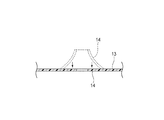
図6(a)及び図6(b)は、上述のように、メイングラフト10を、大動脈60と分岐動脈70との分岐位置の近傍の大動脈60に留置した場合の一例を示す。図6では、便宜上、分岐動脈70は1本のみ図示されている。
6 (a) and 6 (b) show an example of the case where the
図6(a)は、メイングラフト10の筒状開口部14と分岐動脈70との位置が一致している状態を示す。このように、筒状開口部14と分岐動脈70との位置が一致した状態では、大動脈60から分岐動脈70へ向かう血液流(図中の矢印)により、筒状開口部14の開口向きが分岐動脈70の血管口に向かうようになっている。
FIG. 6A shows a state in which the
一方、図6(b)に示すように、メイングラフト10の筒状開口部14と分岐動脈70との間に位置ずれが生じた状態では、筒状開口部14は、大動脈60から分岐動脈70へ向かう血液流(図中の矢印)により、筒状開口部14の開口向きが分岐動脈70の血管口に向かうように変形するようになっている。これは、上述したように、筒状開口部14が柔軟性(フレキシビリティ)を有することに因る。更に、上述したように、筒状開口部14の全体が窪み空間15の内側に存在するため、筒状開口部14と分岐動脈70との間に位置ずれが生じていても、筒状開口部14の開口端が大動脈60の内壁面に接触(干渉)することがない。
On the other hand, as shown in FIG. 6B, in a state where the
なお、図6(b)には、メイングラフト10が分岐動脈70に対してメイングラフト10の軸線方向にオフセットするような位置ずれが生じた場合の例が示されている。但し、上記説明から理解されるように、メイングラフト10がその軸線周りに回転するような位置ずれが生じた場合であっても、上記同様、筒状開口部14の開口向きが分岐動脈70の血管口に向かうように変形することになる。
Note that FIG. 6B shows an example in which the
また、上述したように、メイングラフト10は、典型的には、ブランチグラフト20が接続された状態にて使用されるが、図6に示すように、メイングラフト10単独でも使用され得る。即ち、大動脈瘤等の位置によっては(例えば、大動脈瘤等が図6(a)の大動脈60の下側(分岐動脈70とは反対側)に存在する場合には)メイングラフト10単独であっても、大動脈瘤等への血液流入を遮断しつつ、分岐動脈70への血液流を維持できる。
Further, as described above, the
図7は、図6(a)に示したように大動脈60に留置されたメイングラフト10の筒状開口部14にブランチグラフト20の接続側端部23が接続され、且つ、分岐動脈70にブランチグラフト20が留置された場合の一例を示す。ブランチグラフト20の留置も、ステントグラフト留置装置1を用いて上記同様に行われ得る。
In FIG. 7, the connecting side end 23 of the
具体的には、図6(a)に示したようにメイングラフト10の留置が完了した後、先ず、ブランチグラフト20を保持部52に保持した状態にあるステントグラフト留置装置1におけるガイドワイヤ(図示省略)の先端側を、メイングラフト10の内側から筒状開口部14を経由して分岐動脈70に通しておく。次いで、分岐動脈70に通されたガイドワイヤに案内されながら、ステントグラフト留置装置1全体を、メイングラフト10の内側から筒状開口部14を経由して分岐動脈70内の所定位置まで進行させる。そして、上述した図5(c)〜図5(f)と同様の手順を経て、ブランチグラフト20を分岐動脈70内で完全に露出させて自己拡張させた状態にて、ステントグラフト留置装置1全体を抜き取ることにより、ブランチグラフト20の留置が完了する。なお、上記とは逆に、ブランチグラフト20は、分岐動脈70を経由してメイングラフト10に通されたガイドワイヤ(図示省略)を利用し、メイングラフト10の外側(分岐動脈70側)から筒状開口部14に取り付けられてもよい。
Specifically, after the placement of the
図7(b)に示すように、ブランチグラフト20の留置が完了した状態では、上述した拡径形状を有するブランチグラフト20の接続側端部23の外表面と、上述した縮径形状を有するメイングラフト10の筒状開口部14の内表面と、が密着するように、メイングラフト10とブランチグラフト20とが接続される。これにより、このような縮径部分および拡径部分が存在しない場合に比べ、両者の接触面積が増大し、両者の間の液密性を向上できる。その結果、メイングラフト10とブランチグラフト20との間からの血液の漏れ(いわゆるエンドリーク)を抑制できる。
As shown in FIG. 7B, when the placement of the
<作用・効果>
以上、本発明の実施形態に係るメイングラフト10によれば、メイングラフト10の外周面に径方向内側に窪んだ凹部13が形成されており、その凹部13内に径方向外側に向けて延びる筒状開口部14が形成されている。そのため、メイングラフト10が大動脈60に留置される際、仮にメイングラフト10と分岐動脈70との間に位置ずれが生じたとしても、凹部13内にて筒状開口部14が開く(径方向外側に延びる)ことができる分、従来ステントグラフト(背景技術の欄を参照)に比べて位置ずれに対する許容度が大きい。よって、メイングラフト10は、ステントグラフトとしての機能(例えば、分岐動脈70への血流確保)を維持しながら、従来ステントグラフトに比べ、大動脈60への留置が容易である。換言すると、メイングラフト10は、留置時の位置精度が仮に不十分であったとしても、ステントグラフトとしての機能を十分に発揮することが可能である。
<Action / effect>
As described above, according to the
なお、このように大動脈60に留置されたメイングラフト10(筒状開口部14)と、分岐動脈70に留置されたブランチグラフト20と、を接続することにより、大動脈60と分岐動脈70との分岐位置の近傍に生じた大動脈瘤等への血液流入を遮断し、そのような大動脈瘤等であっても治療することが可能となる。
By connecting the main graft 10 (cylindrical opening 14) indwelled in the
更に、筒状開口部14は、骨格部11を有さず、大動脈60から分岐した血液流によって筒状開口部14の開口向きが変形可能な程度の柔軟性(フレキシビリティ)を有する。よって、メイングラフト10の筒状開口部14と分岐動脈70との間に位置ずれが生じたとしても、分岐動脈70に向かう血液流によって筒状開口部14が自然に案内されることになる。更に、ブランチグラフト20との密着性も向上することになる。
Further, the
更に、筒状開口部14の全体が凹部13による窪み空間15の内側に存在する。そのため、メイングラフト10の筒状開口部14と分岐動脈70との間に位置ずれが生じたとしても、筒状開口部14の開口端が大動脈60の内壁面に接触(干渉)することがない。
Further, the entire
更に、筒状開口部14と凹部13との接続箇所の近傍に骨格部11が存在しない。そのため、筒状開口部14の開口向きの自由度(筒状開口部14の柔軟性)が更に高まる。
Further, the
更に、筒状開口部14が縮径形状(いわゆるテーパ形状)を有する。そのため、メイングラフト10を径方向内側に収縮させた収縮状態として、患部への留置用のステントグラフト留置装置1に収容する際、筒状開口部14が、その接続端から徐々に径方向内側に畳まれて筒状開口部14同士の重なりが生じにくいため、畳み込みが容易になる。
Further, the
更に、本発明の実施形態に係るステントグラフトセットによれば、拡径形状を有するブランチグラフト20の接続側端部23の外表面と、縮径形状を有するメイングラフト10の筒状開口部14の内表面と、が密着するように、メイングラフト10とブランチグラフト20とが接続される。これにより、両者の間の液密性を向上させ、メイングラフト10とブランチグラフト20との間からの血液漏れ(エンドリーク)を抑制できる。
Further, according to the stent graft set according to the embodiment of the present invention, the outer surface of the connecting
<他の態様>
なお、本発明は上記各実施形態に限定されることはなく、本発明の範囲内において種々の変形例を採用できる。例えば、本発明は、上述した実施形態に限定されるものではなく、適宜、変形、改良、等が可能である。その他、上述した実施形態における各構成要素の材質、形状、寸法、数、配置箇所、等は本発明を達成できるものであれば任意であり、限定されない。
<Other aspects>
The present invention is not limited to the above embodiments, and various modifications can be adopted within the scope of the present invention. For example, the present invention is not limited to the above-described embodiment, and can be appropriately modified, improved, and the like. In addition, the material, shape, size, number, arrangement location, etc. of each component in the above-described embodiment are arbitrary and are not limited as long as the present invention can be achieved.
例えば、上記実施形態では、図2(a)に示すように、メイングラフト10が、展開状態において、直線的に延びる管形状を有している。しかし、メイングラフト10が、図8(a)に示すように、展開状態において凹部13および筒状開口部14が外側に位置するように湾曲した管形状を有していても、図8(b)に示すように、展開状態において、凹部13および筒状開口部14が内側に位置するように湾曲した管形状を有していてもよい。なお、このようにメイングラフト10が湾曲した管形状を有する場合の窪み空間15についても、図8(a)及び図8(b)に記載されている。
For example, in the above embodiment, as shown in FIG. 2A, the
更に、上記実施形態では、図7(b)に示すように、拡径形状を有するブランチグラフト20の接続側端部23の外表面と、縮径形状を有するメイングラフト10の筒状開口部14の内表面と、が密着するように、メイングラフト10とブランチグラフト20とが接続されている。しかし、図9に示すように、このような縮径部分および拡径部分が存在しなくても、ブランチグラフト20の接続側端部23の外表面と、メイングラフト10の筒状開口部14の内表面と、が密着するように、メイングラフト10とブランチグラフト20とが接続され得る。
Further, in the above embodiment, as shown in FIG. 7B, the outer surface of the connecting
更に、上記実施形態では、凹部13及び筒状開口部14が分岐動脈70と一対一に対応している。しかし、図10に示すように、複数の筒状開口部14(図10では3つ)の各々が、複数の分岐動脈70の各々に対応するように一つの凹部13から延びるように、メイングラフト10が構成されてもよい。図10では、筒状開口部14の各々と、分岐動脈70の各々に留置したブランチグラフト20と、が接続されている。本構成のメイングラフト10によれば、一つの凹部13によって複数の分岐動脈70に対応できる。このようなメイングラフト10を用いれば、例えば、複数の分岐動脈70が近接する位置(例えば、図10の大動脈60の上側)に生じた大動脈瘤等の治療も可能である。更に、図示は省略するが、メイングラフト10に複数の凹部13を設け、それら複数の凹部13の各々に一又は複数の筒状開口部14を配置してもよい。
Further, in the above embodiment, the
更に、上記実施形態では、筒状開口部14の全体が、凹部13によって形成される窪み空間15の内側に存在している。しかし、筒状開口部14の開口端が窪み空間15の外側に突出していてもよい。加えて、上記実施形態では、凹部13の底面、及び、筒状開口部14には骨格部11が存在しないが、筒状開口部14の基端の近傍を除く凹部13の底面には骨格部11が存在していてもよい。
Further, in the above embodiment, the entire
更に、上記実施形態では、メイングラフト10が、大動脈60の患部(大動脈瘤等が形成されている箇所)に留置され、ブランチグラフト20が、患部近傍の大動脈60から分岐する分岐動脈70に留置されている。しかし、メイングラフト10が、大動脈以外の動脈の患部(動脈瘤が形成されている箇所)に留置され、ブランチグラフト20が、患部近傍の当該動脈から分岐する動脈に留置されていてもよい。
Further, in the above embodiment, the
1 ステントグラフト留置装置
10 メイングラフト(第1ステントグラフト)
11 骨格部
12 皮膜部
13 凹部
14 筒状開口部
15 窪み空間
20 ブランチグラフト(第2ステントグラフト)
23 接続側端部(開口端)
30 第1シース(収容具)
40 第2シース(収容具)
50 ロッド部材(操作具)
60 大動脈(主血管)
70 分岐動脈(分岐血管)
1 Stent graft
11
23 Connection side end (open end)
30 First sheath (container)
40 Second sheath (container)
50 Rod member (operation tool)
60 Aorta (main blood vessel)
70 bifurcated artery (branched blood vessel)
Claims (6)
径方向内側への収縮及び径方向外側への拡張が可能な骨格部と、
前記骨格部に沿って設けられた皮膜部と、を備え、
前記骨格部が収縮した収縮状態から、前記骨格部が拡張して前記皮膜部によって前記流路が画成された拡張状態へ、変形可能であり、
前記拡張状態において、外周面の一部が径方向内側に窪み、平面状の底面を有する凹部と、前記凹部の前記底面の所定位置から径方向外側に向けて延びる筒状に形成され、前記血液流が通過可能な筒状開口部と、を有し、
前記筒状開口部が、
前記流路から分流して当該筒状開口部を通過する血液流によって当該筒状開口部の開口向きを変更可能な柔軟性を有する、
ステントグラフト。 A tubular stent graft that defines a flow path through which blood flows.
A skeleton that can contract inward in the radial direction and expand outward in the radial direction,
A film portion provided along the skeleton portion is provided.
It is possible to deform from the contracted state in which the skeleton portion is contracted to the expanded state in which the skeleton portion is expanded and the flow path is defined by the film portion.
Wherein in the expanded state, see recessed portion is radially inward of the outer peripheral surface is formed a recess having a planar bottom surface, a cylindrical shape extending radially outward from a predetermined position of the bottom surface of the recess, the blood flow is closed and the cylindrical opening capable of passing, and
The tubular opening
To have the opening facing the changeable flexibility of the cylindrical opening by the blood flow through the cylindrical opening diverted from the flow channel,
Stent graft.
前記筒状開口部の全体が、
前記拡張状態において、前記凹部によって画成される窪み空間の内側に存在する、
ステントグラフト。 In the stent graft according to claim 1,
The entire tubular opening
In the expanded state, it exists inside the recessed space defined by the recesses.
Stent graft.
前記骨格部が、
前記筒状開口部と前記凹部との接続箇所の近傍に存在しない、
ステントグラフト。 In the stent graft according to claim 1 or 2.
The skeleton
It does not exist near the connection point between the tubular opening and the recess.
Stent graft.
前記第1ステントグラフトが有する前記筒状開口部へ接続可能な管状の第2ステントグラフトと、を備えた、
ステントグラフトセット。 The first stent graft, which is the stent graft according to any one of claims 1 to 3,
A tubular second stent graft that can be connected to the tubular opening of the first stent graft.
Stent graft set.
前記筒状開口部が、
該筒状開口部と前記凹部との接続箇所から離れるにつれて開口面積が小さくなる縮径形状を有し、
前記第2ステントグラフトが、
開口端の近傍において、前記開口端に近付くにつれて開口面積が大きくなる拡径形状を有し、
前記第1ステントグラフトの前記筒状開口部と、前記第2ステントグラフトの前記開口端の近傍と、が互いに密着する、
ステントグラフトセット。 In the stent graft set according to claim 4,
The tubular opening
It has a reduced diameter shape in which the opening area becomes smaller as the distance from the connection point between the tubular opening and the recess is increased.
The second stent graft
In the vicinity of the opening end, it has an enlarged diameter shape in which the opening area increases as it approaches the opening end.
The tubular opening of the first stent graft and the vicinity of the opening end of the second stent graft are in close contact with each other.
Stent graft set.
請求項1〜請求項3の何れか一項に記載のステントグラフトと、
前記ステントグラフトが前記収縮状態にて収容された収容具と、
前記収容具から前記ステントグラフトを放出して前記拡張状態に変形させる操作具と、
を備えた、
ステントグラフト留置装置。 A stent graft indwelling device for indwelling a stent graft in a blood vessel.
The stent graft according to any one of claims 1 to 3.
A container in which the stent graft is housed in the contracted state and
An operating tool that releases the stent graft from the container and transforms it into the expanded state.
With,
Stent graft indwelling device.
Priority Applications (1)
| Application Number | Priority Date | Filing Date | Title |
|---|---|---|---|
| JP2016194754A JP6832111B2 (en) | 2016-09-30 | 2016-09-30 | Stent graft, stent graft set, and stent graft indwelling device |
Applications Claiming Priority (1)
| Application Number | Priority Date | Filing Date | Title |
|---|---|---|---|
| JP2016194754A JP6832111B2 (en) | 2016-09-30 | 2016-09-30 | Stent graft, stent graft set, and stent graft indwelling device |
Publications (3)
| Publication Number | Publication Date |
|---|---|
| JP2018051259A JP2018051259A (en) | 2018-04-05 |
| JP2018051259A5 JP2018051259A5 (en) | 2019-11-07 |
| JP6832111B2 true JP6832111B2 (en) | 2021-02-24 |
Family
ID=61833222
Family Applications (1)
| Application Number | Title | Priority Date | Filing Date |
|---|---|---|---|
| JP2016194754A Active JP6832111B2 (en) | 2016-09-30 | 2016-09-30 | Stent graft, stent graft set, and stent graft indwelling device |
Country Status (1)
| Country | Link |
|---|---|
| JP (1) | JP6832111B2 (en) |
Families Citing this family (8)
| Publication number | Priority date | Publication date | Assignee | Title |
|---|---|---|---|---|
| JP7258765B2 (en) * | 2017-10-20 | 2023-04-17 | Sbカワスミ株式会社 | Tubular therapeutic device, tubular therapeutic device set and tubular therapeutic device placement device |
| CN108420570A (en) * | 2018-04-19 | 2018-08-21 | 亢顺飞 | A kind of aorta tectorial membrane stent |
| US11844681B2 (en) | 2018-09-27 | 2023-12-19 | SB-Kawasumi Laboratories, Inc. | Stent graft with a position adjustment portion |
| CN109498212A (en) * | 2018-12-04 | 2019-03-22 | 无锡市人民医院 | A kind of overlay film frame dilator |
| CN109646160A (en) * | 2019-01-29 | 2019-04-19 | 戴向晨 | Branched membrane-covered support in a kind of novel aorta |
| WO2021219074A1 (en) * | 2020-04-30 | 2021-11-04 | 杭州唯强医疗科技有限公司 | Covered stent |
| CN112022429A (en) * | 2020-09-27 | 2020-12-04 | 北京裕恒佳科技有限公司 | Branch artificial blood vessel repair system |
| CN116407327A (en) * | 2021-12-30 | 2023-07-11 | 先健科技(深圳)有限公司 | Branch bracket |
Family Cites Families (3)
| Publication number | Priority date | Publication date | Assignee | Title |
|---|---|---|---|---|
| AU2010202544B1 (en) * | 2010-06-18 | 2010-08-26 | Cook Incorporated | Side branch stent graft |
| CA2748206C (en) * | 2010-08-21 | 2015-06-23 | Blayne A. Roeder | Prosthesis having pivoting fenestration |
| US9254209B2 (en) * | 2011-07-07 | 2016-02-09 | Endospan Ltd. | Stent fixation with reduced plastic deformation |
-
2016
- 2016-09-30 JP JP2016194754A patent/JP6832111B2/en active Active
Also Published As
| Publication number | Publication date |
|---|---|
| JP2018051259A (en) | 2018-04-05 |
Similar Documents
| Publication | Publication Date | Title |
|---|---|---|
| JP6832111B2 (en) | Stent graft, stent graft set, and stent graft indwelling device | |
| US11779454B2 (en) | Vascular prosthesis with crimped adapter and methods of use | |
| US11801129B2 (en) | Vascular prosthesis with fenestration ring and methods of use | |
| JP5841120B2 (en) | Preload wire for intraluminal devices | |
| JP4694575B2 (en) | Bifurcated vascular graft design and deployment method | |
| JP6131441B2 (en) | Movable external coupling for branch vessel connection | |
| JP6531994B2 (en) | Stent graft | |
| JP2012523891A (en) | Antegrade deployment prosthesis | |
| JP2009532111A (en) | Prosthesis with guide lumen | |
| CN106923931B (en) | Covered stent | |
| US20210106444A1 (en) | Endovascular prosthesis with selectively openable internal duct | |
| GB2516928A (en) | Prosthesis Device | |
| JP6770875B2 (en) | Stent graft, stent graft set, and stent graft indwelling device | |
| JP2023085467A (en) | Tubular treatment tool, tubular treatment tool set and tubular treatment tool detention device | |
| WO2019181821A1 (en) | Indwelling device and cylindrical treatment tool | |
| US20180353280A1 (en) | Infarction prevention device and treatment method | |
| US20150112418A1 (en) | Segmented Balloon Expandable Stent Graft With Reduced Foreshortening | |
| JPWO2019139077A1 (en) | Intravascular indwelling device and intravascular indwelling system | |
| US11484423B2 (en) | Apparatuses to facilitate prosthesis placement | |
| CN116269964A (en) | Delivery system for delivering cardiovascular devices | |
| JP2021013405A (en) | Intravascular detention tool coupling structure and intravascular detention system | |
| CN115243647A (en) | Branch stent graft delivery system | |
| CN117122443A (en) | Branched stent graft with support stent | |
| WO2014045428A1 (en) | Indwelling device |
Legal Events
| Date | Code | Title | Description |
|---|---|---|---|
| A521 | Request for written amendment filed |
Free format text: JAPANESE INTERMEDIATE CODE: A523 Effective date: 20190924 |
|
| A621 | Written request for application examination |
Free format text: JAPANESE INTERMEDIATE CODE: A621 Effective date: 20190924 |
|
| A977 | Report on retrieval |
Free format text: JAPANESE INTERMEDIATE CODE: A971007 Effective date: 20200626 |
|
| A131 | Notification of reasons for refusal |
Free format text: JAPANESE INTERMEDIATE CODE: A131 Effective date: 20200721 |
|
| A601 | Written request for extension of time |
Free format text: JAPANESE INTERMEDIATE CODE: A601 Effective date: 20200916 |
|
| A521 | Request for written amendment filed |
Free format text: JAPANESE INTERMEDIATE CODE: A523 Effective date: 20201030 |
|
| TRDD | Decision of grant or rejection written | ||
| A01 | Written decision to grant a patent or to grant a registration (utility model) |
Free format text: JAPANESE INTERMEDIATE CODE: A01 Effective date: 20210105 |
|
| A61 | First payment of annual fees (during grant procedure) |
Free format text: JAPANESE INTERMEDIATE CODE: A61 Effective date: 20210201 |
|
| R150 | Certificate of patent or registration of utility model |
Ref document number: 6832111 Country of ref document: JP Free format text: JAPANESE INTERMEDIATE CODE: R150 |
|
| R250 | Receipt of annual fees |
Free format text: JAPANESE INTERMEDIATE CODE: R250 |