JP6830786B2 - Absorbent article manufacturing equipment and method of manufacturing absorbent articles - Google Patents

Absorbent article manufacturing equipment and method of manufacturing absorbent articles Download PDF

Info

Publication number
JP6830786B2
JP6830786B2 JP2016197345A JP2016197345A JP6830786B2 JP 6830786 B2 JP6830786 B2 JP 6830786B2 JP 2016197345 A JP2016197345 A JP 2016197345A JP 2016197345 A JP2016197345 A JP 2016197345A JP 6830786 B2 JP6830786 B2 JP 6830786B2
Authority
JP
Japan
Prior art keywords
gas
tow
outlet
absorbent article
fiber
Prior art date
Legal status (The legal status is an assumption and is not a legal conclusion. Google has not performed a legal analysis and makes no representation as to the accuracy of the status listed.)
Active
Application number
JP2016197345A
Other languages
Japanese (ja)
Other versions
JP2018059240A (en
Inventor
真悟 永田
真悟 永田
雅人 重松
雅人 重松
淳之介 橋田
淳之介 橋田
Current Assignee (The listed assignees may be inaccurate. Google has not performed a legal analysis and makes no representation or warranty as to the accuracy of the list.)
Daicel Corp
Original Assignee
Daicel Corp
Priority date (The priority date is an assumption and is not a legal conclusion. Google has not performed a legal analysis and makes no representation as to the accuracy of the date listed.)
Filing date
Publication date
Application filed by Daicel Corp filed Critical Daicel Corp
Priority to JP2016197345A priority Critical patent/JP6830786B2/en
Publication of JP2018059240A publication Critical patent/JP2018059240A/en
Application granted granted Critical
Publication of JP6830786B2 publication Critical patent/JP6830786B2/en
Active legal-status Critical Current
Anticipated expiration legal-status Critical

Links

Images

Description

本発明は、吸収性物品製造装置及び吸収性物品の製造方法に関する。 The present invention relates to an absorbent article manufacturing apparatus and a method for producing an absorbent article.

紙おむつや尿漏れ防止用パッド等の吸収性物品は、例えば、水分を吸収する吸収体と、液透過性を有するトップシートと、通気性を有するバックシートとを備えている。吸収体は、例えば、特許文献1又は2に開示される開繊装置を用いて、複数本の捲縮された繊維からなるベール状のトウを搬送しながら開繊して製造される。吸収体には、高吸水性樹脂(Super absorbent polymer : SAP)からなる粒状物が添加される場合がある。粒状物は、例えば、気体により開繊されるトウの繊維間隙に分散して配置される。このような構造を有する吸収性物品では、例えば、トップシートに形成された微細孔を通じて、水分が吸収体の内部に拡散し、粒状物に吸収される。 Absorbent articles such as disposable diapers and urine leakage prevention pads include, for example, an absorbent body that absorbs moisture, a top sheet having liquid permeability, and a back sheet having breathability. The absorber is produced by, for example, using the fiber-spreading device disclosed in Patent Document 1 or 2 to spread the fibers while transporting a veil-shaped tow composed of a plurality of crimped fibers. Granules made of a super absorbent polymer (SAP) may be added to the absorber. The granules are dispersed and arranged in the fiber gaps of the tow, which is opened by gas, for example. In an absorbent article having such a structure, for example, moisture is diffused inside the absorber through the micropores formed in the top sheet and absorbed by the granules.

特開2011−241487号公報Japanese Unexamined Patent Publication No. 2011-241487 特開2013−112909号公報Japanese Unexamined Patent Publication No. 2013-112909

従来の吸収性物品の製造方法では、吸収体の内部に粒状物を均一に分散させて配置させることは難しく、吸収体に添加された粒状物が、トウの内部に偏在することがある。これにより、吸収性物品の吸水性能が部分的にばらつくおそれがある。 In the conventional method for producing an absorbent article, it is difficult to uniformly disperse and arrange the granules inside the absorber, and the granules added to the absorber may be unevenly distributed inside the tow. As a result, the water absorption performance of the absorbent article may partially vary.

そこで本発明は、内部に吸水性の粒状物が配置された吸収体を備える吸収性物品を製造する場合において、吸収体の内部に粒状物を均一に分散して配置可能にすることを目的としている。 Therefore, an object of the present invention is to make it possible to uniformly disperse and arrange granules inside the absorber in the case of producing an absorbent article having an absorber in which water-absorbent granules are arranged. There is.

上記課題を解決するために、本発明の一態様に係る吸収性物品製造装置は、搬送されるトウを気体で開繊する開繊室を含む搬送路が形成された気体開繊装置と、前記開繊室の出口よりも前記トウの搬送方向の上流側に位置する添加位置において、吸水性の粒状物を前記トウに添加する添加装置と、を備え、前記添加位置の下方に前記出口が配置された状態で、前記添加位置から前記出口へ向けて、前記トウが上方から下方へ搬送される。 In order to solve the above problems, the absorbent article manufacturing apparatus according to one aspect of the present invention includes a gas fiber opening device in which a transport path including a fiber opening chamber for opening the transported toe with gas is formed. An addition device for adding water-absorbing granules to the tow is provided at an addition position located upstream of the outlet of the fiber opening chamber in the transport direction of the toe, and the outlet is arranged below the addition position. In this state, the toe is conveyed from above to below from the addition position toward the outlet.

上記構成によれば、開繊室の出口よりもトウの搬送方向の上流側に位置する添加位置の下方に開繊室の出口が配置された状態で、添加位置から開繊室の出口へ向けて、トウが上方から下方へ搬送されると共に、添加位置において、吸水性の粒状物がトウに添加されるので、開繊室でトウが開繊される際、粒状物に対して、トウの搬送方向に垂直な方向に重力が作用するのが抑制される。これにより、トウの内部において重力により粒状物が偏在するのが抑制され、トウの内部に粒状物を均一に分散して配置し易くできる。 According to the above configuration, the outlet of the fiber opening chamber is arranged below the addition position located upstream of the outlet of the fiber opening chamber in the transport direction of the toe, and the outlet of the fiber opening chamber is directed from the addition position to the outlet of the fiber opening chamber. As the tow is transported from the upper side to the lower side, water-absorbent granules are added to the tow at the addition position. Therefore, when the tow is opened in the defibration chamber, the tow is added to the granules. Gravity is suppressed from acting in the direction perpendicular to the transport direction. As a result, the uneven distribution of the granules due to gravity inside the toe is suppressed, and the granules can be easily dispersed and arranged inside the toe.

前記添加位置の真下に前記出口が配置された状態で、前記添加位置から前記出口へ向けて、前記トウが鉛直方向に搬送されてもよい。これにより、トウの内部において重力により粒状物が偏在するのが更に抑制され、トウの内部に粒状物を一層均一に分散して配置し易くできる。 The tow may be conveyed in the vertical direction from the addition position toward the outlet in a state where the outlet is arranged directly below the addition position. As a result, the uneven distribution of the granules due to gravity inside the toe is further suppressed, and the granules can be more uniformly dispersed and arranged inside the toe.

前記添加位置は、前記開繊室の入口よりも前記上流側に位置していてもよい。これにより、開繊室においてトウを開繊しながら、効率よく粒状物をトウの繊維間隙に分散して配置し易くできる。 The addition position may be located on the upstream side of the entrance of the fiber opening chamber. As a result, the granules can be efficiently dispersed and arranged in the fiber gaps of the tow while opening the tow in the fiber opening chamber.

前記気体開繊装置は、前記出口を通過した前記トウを一時的に滞留させる滞留部を有し、前記出口を通過した前記トウが、前記滞留部を鉛直方向に通過してもよい。これにより、トウの内部に粒状物が均一に分散されて配置された状態を維持しながら、トウの繊維密度を滞留部で高めることができる。 The gas spreading apparatus may have a retention portion for temporarily retaining the tow that has passed through the outlet, and the tow that has passed through the outlet may pass through the retention portion in the vertical direction. As a result, the fiber density of the toe can be increased at the stagnant portion while maintaining the state in which the granules are uniformly dispersed and arranged inside the toe.

前記気体開繊装置は、前記搬送路に前記気体を導入する気体導入口を有し、前記添加位置は、前記気体導入口よりも前記上流側に位置してもよい。これにより、気体導入口から搬送路に導入される気体によって、添加位置から導入される粒状物を、トウの内部に良好に分散して配置できる。 The gas opening device may have a gas introduction port for introducing the gas into the transport path, and the addition position may be located on the upstream side of the gas introduction port. As a result, the granules introduced from the addition position can be satisfactorily dispersed and arranged inside the toe by the gas introduced from the gas introduction port into the transport path.

前記気体開繊装置よりも前記上流側において、前記トウを周面に接触させて開繊する複数対の開繊ロール対を備えてもよい。これにより、複数対の開繊ロール対により開繊されたトウを、気体開繊装置により、更に嵩高に絡み合わせながら開繊できるので、繊維間隙を広げたトウの内部に、粒状物を均一に分散し易くできる。 A plurality of pairs of opening rolls may be provided on the upstream side of the gas opening device so that the toe is brought into contact with the peripheral surface to open the fibers. As a result, the tow opened by a plurality of pairs of opening rolls can be opened while being entwined in a bulky manner by the gas opening device, so that the granules can be uniformly dispersed inside the tow with widened fiber gaps. It can be easily dispersed.

本発明の一態様に係る吸収性物品の製造方法は、搬送されるトウを気体で開繊する開繊室を含む搬送路が形成された気体開繊装置と、吸水性の粒状物を前記トウに添加する添加装置とを用い、前記開繊室の出口よりも前記トウの搬送方向の上流側に位置し且つ前記添加装置が前記粒状物を前記トウに添加する添加位置の下方に前記出口を配置した状態で、前記添加位置から前記出口へ向けて、前記トウを上方から下方へ搬送する。 In the method for producing an absorbent article according to one aspect of the present invention, a gas fiber opening device having a transport path including a fiber opening chamber for opening the tow to be transported with a gas and a water-absorbent granular material are used as the tow. The outlet is located upstream of the outlet of the fiber opening chamber in the transport direction of the tow, and the outlet is located below the addition position where the addition device adds the granules to the tow. In the arranged state, the toe is conveyed from above to below from the addition position toward the outlet.

前記添加位置の真下に前記出口を配置した状態で、前記添加位置から前記出口へ向けて、前記トウを鉛直方向に搬送してもよい。 The tow may be conveyed in the vertical direction from the addition position toward the outlet in a state where the outlet is arranged directly below the addition position.

前記添加位置を、前記開繊室の入口よりも前記上流側に位置させてもよい。 The addition position may be located on the upstream side of the entrance of the defibration chamber.

前記出口を通過した前記トウを一時的に滞留させる滞留部を有する前記気体開繊装置を用い、前記出口を通過した前記トウを、前記滞留部に鉛直方向に通過させてもよい。 The gas spreading device having a retention portion for temporarily retaining the tow that has passed through the outlet may be used, and the tow that has passed through the outlet may be passed through the retention portion in the vertical direction.

前記搬送路に前記気体を導入する気体導入口を有する前記気体開繊装置を用い、前記添加位置を、前記気体導入口よりも前記上流側に位置させてもよい。 The gas opening device having a gas introduction port for introducing the gas into the transport path may be used, and the addition position may be located on the upstream side of the gas introduction port.

前記気体開繊装置よりも前記上流側において、前記トウを複数対の開繊ロール対の周面に接触させて開繊してもよい。 The tow may be brought into contact with the peripheral surfaces of a plurality of pairs of opening rolls to open the fibers on the upstream side of the gas opening device.

本発明の各態様によれば、内部に吸水性の粒状物が配置された吸収体を備える吸収性物品を製造する場合において、吸収体の内部に粒状物を均一に分散して配置できる。 According to each aspect of the present invention, in the case of producing an absorbent article including an absorber in which water-absorbent granules are arranged, the granules can be uniformly dispersed and arranged inside the absorber.

第1実施形態に係る吸収性物品製造装置の側面図である。It is a side view of the absorbent article manufacturing apparatus which concerns on 1st Embodiment. 図1の気体開繊装置と添加装置とのトウバンドの幅方向から見た鉛直断面図である。It is a vertical cross-sectional view seen from the width direction of the tow band of the gas opening apparatus and the addition apparatus of FIG. 粒状物が添加された従来のトウバンドの搬送方向から見た鉛直断面図である。It is a vertical cross-sectional view seen from the transport direction of the conventional tow band to which granular matter was added. 図1の滞留部を通過し且つ搬送ロール対より上流側を搬送されるトウバンドの搬送方向から見た鉛直断面図である。It is a vertical cross-sectional view seen from the transport direction of the tow band that passes through the retention portion of FIG. 1 and is transported on the upstream side of the transport roll pair. 図1の吸収性物品製造装置により製造された吸収性物品の搬送方向から見た鉛直断面図である。It is a vertical cross-sectional view seen from the transport direction of the absorbent article manufactured by the absorbent article manufacturing apparatus of FIG. 第2実施形態に係る気体開繊装置と添加装置との側面図である。It is a side view of the gas opening apparatus and addition apparatus which concerns on 2nd Embodiment.

以下、各実施形態について、各図を参照して説明する。以下に言及する上流側と下流側とは、トウバンド60の搬送方向Pの上流側と下流側とを順に指す。 Hereinafter, each embodiment will be described with reference to each figure. The upstream side and the downstream side referred to below refer in order to the upstream side and the downstream side of the transport direction P of the toe band 60.

(第1実施形態)
[吸収性物品製造装置]
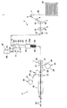
図1は、第1実施形態に係る吸収性物品製造装置1(以下、単に製造装置1と称する。)の全体図である。製造装置1の近傍には、梱包容器50が配置される。梱包容器50には、トウバンド60がベール状に折り畳まれ、且つ圧縮されて梱包されている。図1の梱包容器50は、断面構造を示している。
(First Embodiment)
[Absorbent article manufacturing equipment]
FIG. 1 is an overall view of the absorbent article manufacturing apparatus 1 (hereinafter, simply referred to as manufacturing apparatus 1) according to the first embodiment. A packing container 50 is arranged in the vicinity of the manufacturing apparatus 1. The tow band 60 is folded and compressed into a veil shape and packed in the packing container 50. The packing container 50 of FIG. 1 shows a cross-sectional structure.

トウバンド60に含まれる繊維は、セルロースアセテートトウの長繊維であるが、これ以外の繊維であってもよい。一例として製造装置1では、トウバンド60は、幅方向が水平に保たれながら、搬送方向Pに搬送される。 The fiber contained in the tow band 60 is a long fiber of cellulose acetate tow, but other fibers may be used. As an example, in the manufacturing apparatus 1, the toe band 60 is conveyed in the conveying direction P while keeping the width direction horizontal.

製造装置1は、第1製造部2と第2製造部3とを備える。第1製造部2は、第1拡幅装置4、ガイド5、第2拡幅装置6、第1開繊ロール対7、第2開繊ロール対8、気体開繊装置9、添加装置10、搬送ロール対11、及び複数のフリーロール12を有する。 The manufacturing apparatus 1 includes a first manufacturing unit 2 and a second manufacturing unit 3. The first manufacturing unit 2 includes a first widening device 4, a guide 5, a second widening device 6, a first spread fiber pair 7, a second spread fiber roll pair 8, a gas spreader 9, an addition device 10, and a transfer roll. It has a pair of 11 and a plurality of free rolls 12.

第1拡幅装置4は、梱包容器50の内部から繰り上げられたトウバンド60を、幅方向に拡幅する。ガイド5は、第1拡幅装置4を通過したトウバンド60を、第2拡幅装置6へ向けてガイドする。第2拡幅装置6は、ガイド5を通過したトウバンド60を、更に幅方向に拡幅する。一例として、第1拡幅装置4と第2拡幅装置6とは、同様の構成を有する。第1拡幅装置4と第2拡幅装置6とは、バンディングジェット装置とも称する。 The first widening device 4 widens the tow band 60 carried up from the inside of the packing container 50 in the width direction. The guide 5 guides the toe band 60 that has passed through the first widening device 4 toward the second widening device 6. The second widening device 6 further widens the toe band 60 that has passed through the guide 5 in the width direction. As an example, the first widening device 4 and the second widening device 6 have the same configuration. The first widening device 4 and the second widening device 6 are also referred to as a banding jet device.

第1開繊ロール対7と第2開繊ロール対8とは、気体開繊装置9よりも上流側において、トウバンド60を周面に接触させて開繊する。第2開繊ロール対8は、第1開繊ロール対7よりも下流側に配置されている。第1開繊ロール対7は、互いの周面を対向させて配置された一対のロール13、14を有する。第2開繊ロール対8は、互いの周面を対向させて配置された一対のロール15、16を有する。第2開繊ロール対8は、第1開繊ロール対7の周速度よりも早い周速度で回転する。 The first spread fiber pair 7 and the second spread fiber roll pair 8 are opened by bringing the tow band 60 into contact with the peripheral surface on the upstream side of the gas spreading device 9. The second spread roll pair 8 is arranged on the downstream side of the first spread fiber pair 7. The first spread fiber pair 7 has a pair of rolls 13 and 14 arranged so that their peripheral surfaces face each other. The second spread fiber pair 8 has a pair of rolls 15 and 16 arranged so that their peripheral surfaces face each other. The second spread roll pair 8 rotates at a peripheral speed faster than the peripheral speed of the first spread fiber pair 7.

第2拡幅装置6を通過したトウバンド60は、一対のロール13、14の間と、一対のロール15、16の間とに挿通される。トウバンド60は、ロール13〜16の周面と接触しながら、第1開繊ロール対7と第2開繊ロール対8とにより搬送方向Pに張力を与えられ、嵩高く開繊される。 The tow band 60 that has passed through the second widening device 6 is inserted between the pair of rolls 13 and 14 and between the pair of rolls 15 and 16. The tow band 60 is bulky and opened by applying tension in the transport direction P by the first opening roll pair 7 and the second opening fiber pair 8 while contacting the peripheral surfaces of the rolls 13 to 16.

一対のロール13、14の一方のロールと、一対のロール15、16の一方のロールとの周面には、トウバンド60を幅方向に開繊するための溝部をロール軸周りに螺旋状に形成してもよい。 Grooves for opening the tow band 60 in the width direction are spirally formed around the roll axis on the peripheral surface of one of the pair of rolls 13 and 14 and one of the pair of rolls 15 and 16. You may.

気体開繊装置9は、トウ開繊装置であり、搬送されるトウバンド60を気体Gで開繊する開繊室43aを含む搬送路43が形成されている。気体開繊装置9の上流側と下流側とには、複数のフリーロール12が配置されている。第2開繊ロール対8を通過したトウバンド60は、複数のフリーロール12により案内され、上方から下方へ向けて、気体開繊装置9に導入される。 The gas opening device 9 is a toe opening device, and a transport path 43 including a fiber opening chamber 43a for opening the tow band 60 to be conveyed with gas G is formed. A plurality of free rolls 12 are arranged on the upstream side and the downstream side of the gas spreading apparatus 9. The tow band 60 that has passed through the second spread fiber pair 8 is guided by the plurality of free rolls 12 and is introduced into the gas spreader 9 from above to below.

気体開繊装置9は、導入部17、ジェット発生部18、開繊成型部19、及び滞留部20を有する。気体開繊装置9では、上方から下方へ向けて、導入部17、ジェット発生部18、開繊成型部19、及び滞留部20が順に配置されている。以下、この気体開繊装置9の配置を垂直配置とも称する。 The gas opening device 9 has an introduction unit 17, a jet generating unit 18, a fiber opening molding unit 19, and a retention unit 20. In the gas spreading apparatus 9, the introduction portion 17, the jet generating portion 18, the spreading fiber molding portion 19, and the retaining portion 20 are arranged in this order from the upper side to the lower side. Hereinafter, the arrangement of the gas spreading apparatus 9 is also referred to as a vertical arrangement.

導入部17は、ジェット発生部18の上流側に取り付けられている。導入部17は、ブロック部33とガイド部34とを有する。ブロック部33は直方体状に形成され、搬送方向Pに延びる内部空間27が形成されている。ガイド部34は筒状に形成され、ブロック部33の上側に設けられている。ガイド部34の内径は、下流側から上流側へ向けて拡大されている。導入部17は、第2開繊ロール対8を通過したトウバンド60と、添加装置10により供給される吸水性の粒状物28とをガイド部34により鉛直方向にガイドしながら、ブロック部33の内部空間27に流通させ、ジェット発生部18に導入する。 The introduction unit 17 is attached to the upstream side of the jet generation unit 18. The introduction unit 17 has a block unit 33 and a guide unit 34. The block portion 33 is formed in a rectangular parallelepiped shape, and an internal space 27 extending in the transport direction P is formed. The guide portion 34 is formed in a tubular shape and is provided above the block portion 33. The inner diameter of the guide portion 34 is expanded from the downstream side to the upstream side. The introduction section 17 guides the tow band 60 that has passed through the second spread roll pair 8 and the water-absorbing granules 28 supplied by the addition device 10 in the vertical direction by the guide section 34, and inside the block section 33. It is circulated in the space 27 and introduced into the jet generator 18.

ジェット発生部18は、開繊成型部19の上流側に取り付けられている。ジェット発生部18は円筒状であり、搬送方向Pに延びる内部空間40が形成されている。ジェット発生部18は、内部空間40において、外部から導入される気体Gによりジェットを発生させ、トウバンド60と粒状物28とを混合する。ジェット発生部18は、トウバンド60と粒状物28とを内部空間40に搬送し、開繊成型部19に導入する。 The jet generating portion 18 is attached to the upstream side of the spread fiber molding portion 19. The jet generating portion 18 has a cylindrical shape, and an internal space 40 extending in the transport direction P is formed. In the internal space 40, the jet generating unit 18 generates a jet by the gas G introduced from the outside, and mixes the tow band 60 and the granules 28. The jet generation unit 18 conveys the tow band 60 and the granules 28 to the internal space 40 and introduces them into the spread fiber molding unit 19.

開繊成型部19は筒状であり、内部に搬送方向Pに延びる搬送路43が形成されている。開繊成型部19は、ジェット発生部18を通過したトウバンド60、粒状物28、及び気体Gを搬送路43に搬送しながら混合し、開繊室43aにおいて、トウバンド60を開繊して成型すると共に、トウバンド60の内部に粒状物28を分散して配置する。 The spread fiber molding portion 19 has a tubular shape, and a transport path 43 extending in the transport direction P is formed therein. The fiber-spreading molding section 19 mixes the tow band 60, the granules 28, and the gas G that have passed through the jet generating section 18 while transporting them to the transport path 43, and opens and molds the tow band 60 in the fiber-spreading chamber 43a. At the same time, the granules 28 are dispersed and arranged inside the tow band 60.

滞留部20は、開繊成型部19の下流側に取り付けられている。滞留部20は、搬送路43を通過したトウバンド60を一時的に滞留させる。これにより滞留部20は、トウバンド60の膨張を抑制すると共に、トウバンド60の嵩又は繊維密度を調整する。滞留部20は、複数の長尺部材32を有する。複数の長尺部材32は、搬送路43の周方向で互いに間隔をおきながら、開繊成型部19から下流側へ向けて延設されている。長尺部材32の上流端部は、開繊成型部19の下流端部に接続されている。複数の長尺部材32の下流端部は、上流側から下流側に向かって互いに接近している。開繊室43aの出口を通過したトウバンド60は、滞留部20を鉛直方向に通過する。 The retention portion 20 is attached to the downstream side of the spread fiber molding portion 19. The retention section 20 temporarily retains the toe band 60 that has passed through the transport path 43. As a result, the retention portion 20 suppresses the expansion of the toe band 60 and adjusts the volume or fiber density of the toe band 60. The retention portion 20 has a plurality of long members 32. The plurality of long members 32 extend toward the downstream side from the spread fiber molding portion 19 while being spaced apart from each other in the circumferential direction of the transport path 43. The upstream end of the long member 32 is connected to the downstream end of the spread fiber molding portion 19. The downstream ends of the plurality of elongated members 32 are close to each other from the upstream side to the downstream side. The tow band 60 that has passed through the outlet of the fiber opening chamber 43a passes through the retention portion 20 in the vertical direction.

添加装置10は、気体開繊装置9の開繊室43aの出口よりも上流側に位置する添加位置Nにおいて、吸水性の粒状物28をトウバンド60に添加する。具体的に添加装置10は、ジェット発生部18のトウバンド導入口35b(図2参照)よりも上流側において、粒状物28をトウバンド60に添加する。粒状物28は、一例として高吸水性樹脂からなる。 The addition device 10 adds the water-absorbent granules 28 to the tow band 60 at the addition position N located on the upstream side of the outlet of the fiber opening chamber 43a of the gas fiber opening device 9. Specifically, the addition device 10 adds the granular material 28 to the toe band 60 on the upstream side of the toe band introduction port 35b (see FIG. 2) of the jet generation unit 18. The granular material 28 is made of a highly water-absorbent resin as an example.

ここで製造装置1では、添加位置Nの下方に開繊室43aの出口が配置された状態で、添加位置Nから開繊室43aの出口へ向けて、トウバンド60が上方から下方へ搬送される。一例として製造装置1では、気体開繊装置9において、添加位置Nの真下に開繊室43aの出口が配置された状態で、添加位置Nから開繊室43aの出口へ向けて、トウバンド60が鉛直方向に搬送される。 Here, in the manufacturing apparatus 1, the tow band 60 is conveyed from the upper side to the lower side from the addition position N toward the outlet of the fiber opening chamber 43a in a state where the outlet of the fiber opening chamber 43a is arranged below the addition position N. .. As an example, in the manufacturing apparatus 1, in the gas opening apparatus 9, the toe band 60 is provided from the addition position N toward the outlet of the opening chamber 43a in a state where the outlet of the opening chamber 43a is arranged directly below the addition position N. It is transported in the vertical direction.

添加装置10は、ホッパ21と供給管22とを有する。ホッパ21には、粒状物28が貯留される。供給管22は、ホッパ21に貯留された粒状物28を導入部17に供給する。供給管22の下流端部は、導入部17の上方に配置されている。本実施形態では、添加位置Nは、開繊室43aの入口よりも上流側に位置している。具体的に添加位置Nは、ガイド部34の上端位置に設定されている。 The addition device 10 has a hopper 21 and a supply pipe 22. Granules 28 are stored in the hopper 21. The supply pipe 22 supplies the granules 28 stored in the hopper 21 to the introduction unit 17. The downstream end of the supply pipe 22 is arranged above the introduction portion 17. In the present embodiment, the addition position N is located on the upstream side of the entrance of the fiber opening chamber 43a. Specifically, the addition position N is set at the upper end position of the guide portion 34.

添加装置10は、ホッパ21に貯留された粒状物28を、ベール状のトウバンド60の一方の面(一例として、トウバンド60が開繊ロール対7、8を通過する際には上面に相当する面)に添加する。製造装置1では、供給管22を介して、ホッパ21に貯留された粒状物28を落下させてトウバンド60に添加する。なお、加圧された気体(一例として空気)により、粒状物28を供給管22の下流端部から噴出させ、トウバンド60に添加してもよい。 The adding device 10 transfers the granules 28 stored in the hopper 21 to one surface of the bale-shaped toe band 60 (for example, a surface corresponding to the upper surface when the tow band 60 passes through the spread fiber pairs 7 and 8. ). In the manufacturing apparatus 1, the granules 28 stored in the hopper 21 are dropped and added to the tow band 60 via the supply pipe 22. The granules 28 may be ejected from the downstream end of the supply pipe 22 by a pressurized gas (air as an example) and added to the tow band 60.

また搬送路43は、開繊室43aの上流側又は下流側に配置されたその他の開繊室を含んでいてもよい。この場合、添加装置10は、複数の開繊室のうち、搬送方向Pの最も下流側における開繊室の出口よりも上流側に位置する添加位置Nで、粒状物28をトウバンド60に添加すればよい。またこの場合、添加位置Nは、例えば、複数の開繊室のうち、最も上流側における開繊室の入口よりも上流側に位置していてもよい。 Further, the transport path 43 may include other fiber opening chambers arranged on the upstream side or the downstream side of the fiber opening chamber 43a. In this case, the addition device 10 adds the granular material 28 to the tow band 60 at the addition position N located on the upstream side of the outlet of the fiber opening chamber on the most downstream side of the transport direction P among the plurality of fiber opening chambers. Just do it. Further, in this case, the addition position N may be located, for example, on the upstream side of the inlet of the fiber opening chamber on the most upstream side among the plurality of fiber opening chambers.

搬送ロール対11は、気体開繊装置9の下流側に配置されたフリーロール12を通過したトウバンド60を下流側に搬送する。搬送ロール対11は、平行に軸支された一対の搬送ロール(引取ロールとも称する。)30、31を有する。トウバンド60は、一対の搬送ロール30、31の間に挿通される。トウバンド60は、一対の搬送ロール30、31に引き取られ、一対の搬送ロール30、31により厚み方向に押圧される。これにより、吸収体61が製造される。吸収体61は、搬送ロール対11の下流側の第2製造部3に搬送される。 The transport roll pair 11 transports the tow band 60 that has passed through the free roll 12 arranged on the downstream side of the gas spreading apparatus 9 to the downstream side. The transport roll pair 11 has a pair of transport rolls (also referred to as take-back rolls) 30 and 31 pivotally supported in parallel. The toe band 60 is inserted between the pair of transport rolls 30 and 31. The toe band 60 is picked up by a pair of transport rolls 30 and 31, and pressed in the thickness direction by the pair of transport rolls 30 and 31. As a result, the absorber 61 is manufactured. The absorber 61 is transported to the second manufacturing unit 3 on the downstream side of the transport roll pair 11.

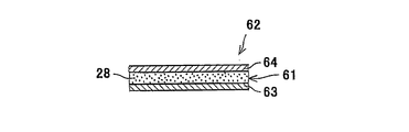
第2製造部3は、吸収体61に対して、バックシート63とトップシート64とを重ねて配置する。第2製造部3は、第1供給装置24、シート搬送装置25、第2供給装置26、添着装置29、シート成型ロール対37、及び、貼着装置38を有する。 The second manufacturing unit 3 arranges the back sheet 63 and the top sheet 64 so as to overlap with the absorber 61. The second manufacturing unit 3 includes a first supply device 24, a sheet transfer device 25, a second supply device 26, an attachment device 29, a sheet molding roll pair 37, and an attachment device 38.

第1供給装置24は、第1シートロール66から帯状のバックシート63を繰り出して、搬送ラインL上に供給する。シート搬送装置25は、バックシート63を搬送ラインLに搬送する。バックシート63の上には、吸収体61が供給される。第2供給装置26は、第2シートロール67から帯状のトップシート64を繰り出して、バックシート63とトップシート64との間で吸収体61を挟むように、トップシート64を搬送ラインL上に供給する。 The first supply device 24 pays out the strip-shaped back sheet 63 from the first sheet roll 66 and supplies it onto the transport line L. The sheet transfer device 25 conveys the back sheet 63 to the transfer line L. The absorber 61 is supplied on the back sheet 63. The second supply device 26 feeds the strip-shaped top sheet 64 from the second sheet roll 67, and puts the top sheet 64 on the transport line L so as to sandwich the absorber 61 between the back sheet 63 and the top sheet 64. Supply.

添着装置29は、第2シートロール67とシート成型ロール対37との間において、トップシート64に接着剤を添着する。シート成型ロール対37は、重ねられたバックシート63、吸収体61、及びトップシート64をシート状に成型しながら下流側に搬送する。貼着装置38は、バックシート63とトップシート64とを厚み方向に押圧して、バックシート63とトップシート64とを吸収体61を挟んだ状態で、接着剤により貼着する。製造装置1では、貼着装置38により貼着されたバックシート63、吸収体61、及び、トップシート64が切断され、所定の寸法の吸収性物品62(図5参照)が製造される。 The adhesive device 29 adheres an adhesive to the top sheet 64 between the second sheet roll 67 and the sheet molding roll pair 37. The sheet molding roll pair 37 conveys the stacked back sheet 63, absorber 61, and top sheet 64 to the downstream side while molding them into a sheet shape. The sticking device 38 presses the back sheet 63 and the top sheet 64 in the thickness direction, and sticks the back sheet 63 and the top sheet 64 with an adhesive in a state of sandwiching the absorber 61. In the manufacturing apparatus 1, the back sheet 63, the absorber 61, and the top sheet 64 attached by the attaching apparatus 38 are cut to produce an absorbent article 62 (see FIG. 5) having a predetermined size.

なお吸収性物品62は、本実施形態ではおむつ用途であるが、当然ながらこれ以外の用途でもよく、例えば、尿漏れ防止用パッド用途であってもよい。吸収性物品62が、尿漏れ防止用パッド用途等である場合、バックシート63は、省略してもよい。 The absorbent article 62 is used for diapers in the present embodiment, but of course, it may be used for other purposes, for example, a pad for preventing urine leakage. When the absorbent article 62 is used as a pad for preventing urine leakage, the back sheet 63 may be omitted.

[気体開繊装置及び添加装置]
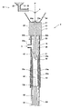
図2は、図1の気体開繊装置9と添加装置10とのトウバンド60の幅方向から見た鉛直断面図である。ガイド部34の下部の中央には、トウバンド60と粒状物28とを通過させる開口34aが設けられている。ブロック部33の下流端部は、ブロック部33の搬送方向Pの内方へ向けて窪んでいる。
[Gas spreader and addition device]
FIG. 2 is a vertical cross-sectional view of the tow band 60 of the gas spreading device 9 and the adding device 10 of FIG. 1 as viewed from the width direction. An opening 34a through which the tow band 60 and the granules 28 pass is provided in the center of the lower portion of the guide portion 34. The downstream end of the block portion 33 is recessed inward in the transport direction P of the block portion 33.

ブロック部33は、トウバンド導入口33aとトウバンド排出口33bとを有する。トウバンド導入口33aは、ブロック部33の上流端面に設けられている。トウバンド導入口33aは、開口34aと鉛直方向に重なっている。トウバンド排出口33bは、ブロック部33の下流端面に設けられている。ブロック部33の下流端部には、ジェット発生部18の上流端部が差し込まれている。内部空間27は、鉛直方向に延びている。内部空間27は、ジェット発生部18のトウバンド導入路42に対して滑らかに接続されている。 The block portion 33 has a toe band introduction port 33a and a toe band discharge port 33b. The toe band introduction port 33a is provided on the upstream end surface of the block portion 33. The toe band introduction port 33a overlaps the opening 34a in the vertical direction. The toe band discharge port 33b is provided on the downstream end surface of the block portion 33. The upstream end of the jet generating portion 18 is inserted into the downstream end of the block portion 33. The internal space 27 extends in the vertical direction. The internal space 27 is smoothly connected to the tow band introduction path 42 of the jet generation unit 18.

ジェット発生部18は、混合部35とノズル部36とを有する。混合部35は、搬送方向Pに延びる管状部である。混合部35は、気体導入口35a、トウバンド導入口35b、及びトウバンド排出口35cを有する。気体導入口35aは、混合部35の上流側の側部に配置されている。トウバンド導入口35bは、混合部35の上流端部に配置されている。トウバンド排出口35cは、混合部35の下流端部に配置されている。 The jet generation unit 18 has a mixing unit 35 and a nozzle unit 36. The mixing portion 35 is a tubular portion extending in the transport direction P. The mixing unit 35 has a gas introduction port 35a, a toe band introduction port 35b, and a toe band discharge port 35c. The gas introduction port 35a is arranged on the upstream side of the mixing portion 35. The tow band introduction port 35b is arranged at the upstream end of the mixing portion 35. The tow band discharge port 35c is arranged at the downstream end of the mixing portion 35.

気体導入口35aは、加圧された気体G(一例として空気)を内部空間40に導入する。これにより気体開繊装置9は、搬送路43に気体Gを導入する気体導入口35aを有している。添加位置Nは、気体導入口35aよりも上流側に位置している。トウバンド導入口35bは、トウバンド60を内部空間40に導入する。内部空間40は、鉛直方向に延びている。混合部35の下流端部は、開繊成型部19に差し込まれている。 The gas introduction port 35a introduces the pressurized gas G (air as an example) into the internal space 40. As a result, the gas spreading device 9 has a gas introduction port 35a for introducing the gas G into the transport path 43. The addition position N is located on the upstream side of the gas introduction port 35a. The toe band introduction port 35b introduces the toe band 60 into the internal space 40. The internal space 40 extends in the vertical direction. The downstream end of the mixing portion 35 is inserted into the spread fiber molding portion 19.

ノズル部36は、内部空間40の上流側に設けられている。ノズル部36の下流側の先端には、テーパー部36aが形成されている。テーパー部36aは、上流側から下流側に向かって、先細りの形状を有する。 The nozzle portion 36 is provided on the upstream side of the internal space 40. A tapered portion 36a is formed at the tip of the nozzle portion 36 on the downstream side. The tapered portion 36a has a tapered shape from the upstream side to the downstream side.

テーパー部36aの外周面と対向する混合部35の内周面は、テーパー部36aの外周面と離隔しながら、上流側から下流側に向かって縮径されている。これにより、テーパー部36aの外周面と混合部35の内周面との間には、ジェット流路41が形成されている。ジェット流路41は、環状断面を有する。ジェット流路41は、気体導入口35aから内部空間40へ導入される気体Gにより、ジェットを発生させて内部空間40に噴出させる。 The inner peripheral surface of the mixing portion 35 facing the outer peripheral surface of the tapered portion 36a is reduced in diameter from the upstream side to the downstream side while being separated from the outer peripheral surface of the tapered portion 36a. As a result, a jet flow path 41 is formed between the outer peripheral surface of the tapered portion 36a and the inner peripheral surface of the mixing portion 35. The jet flow path 41 has an annular cross section. The jet flow path 41 generates a jet by the gas G introduced into the internal space 40 from the gas introduction port 35a and ejects the jet into the internal space 40.

ノズル部36の内部には、トウバンド導入路42が形成されている。トウバンド導入路42は、トウバンド導入口35bから下流側に延びている。トウバンド導入路42は、鉛直方向に延びている。トウバンド導入路42の出口は、気体導入口35aよりも下流側に配置されている。トウバンド導入路42を通過したトウバンド60は、ジェット流路41を通過した気体Gと混合されて内部空間40を流通する。 A toe band introduction path 42 is formed inside the nozzle portion 36. The tow band introduction path 42 extends downstream from the toe band introduction port 35b. The tow band introduction path 42 extends in the vertical direction. The outlet of the toe band introduction path 42 is arranged on the downstream side of the gas introduction port 35a. The tow band 60 that has passed through the tow band introduction path 42 is mixed with the gas G that has passed through the jet flow path 41 and flows through the internal space 40.

なお気体Gは、空気以外の気体でもよい。また、トウバンド導入路42の出口と気体導入口35aとは、側方から見て重なる位置に配置されていてもよい。また、トウバンド導入路42の出口は、気体導入口35aよりも上流側に配置されていてもよい。 The gas G may be a gas other than air. Further, the outlet of the tow band introduction path 42 and the gas introduction port 35a may be arranged at overlapping positions when viewed from the side. Further, the outlet of the tow band introduction path 42 may be arranged on the upstream side of the gas introduction port 35a.

開繊成型部19の上流端部と下流端部とは、開繊成型部19の搬送方向Pの内方へ向けて窪んでいる。開繊成型部19は、トウバンド導入口19aとトウバンド排出口19bとを有する。トウバンド導入口19aとトウバンド排出口19bは、搬送方向Pに離隔している。トウバンド導入口19aは、開繊成型部19の上流端面に配置されている。トウバンド排出口19bは、開繊成型部19の下流端面に配置されている。開繊成型部19の上流端部に混合部35の下流端部が差し込まれることにより、内部空間40は、搬送路43に対して滑らかに接続されている。 The upstream end portion and the downstream end portion of the spread fiber molding portion 19 are recessed inward in the transport direction P of the spread fiber molding portion 19. The spread fiber molding portion 19 has a tow band introduction port 19a and a toe band discharge port 19b. The toe band introduction port 19a and the toe band discharge port 19b are separated from each other in the transport direction P. The tow band introduction port 19a is arranged on the upstream end surface of the spread fiber molding portion 19. The tow band discharge port 19b is arranged on the downstream end surface of the spread fiber molding portion 19. The internal space 40 is smoothly connected to the transport path 43 by inserting the downstream end portion of the mixing portion 35 into the upstream end portion of the spread fiber molding portion 19.

搬送路43は、鉛直方向に延びている。開繊室43aは、搬送路43の長手方向に延びている。本実施形態では、トウバンド導入口19aが開繊室43aの入口に相当し、トウバンド排出口19bが開繊室43aの出口に相当する。開繊成型部19の下流端部には、複数本の長尺部材32の上流端部が差し込まれている。 The transport path 43 extends in the vertical direction. The fiber opening chamber 43a extends in the longitudinal direction of the transport path 43. In the present embodiment, the tow band introduction port 19a corresponds to the entrance of the fiber opening chamber 43a, and the tow band discharge port 19b corresponds to the exit of the fiber opening chamber 43a. The upstream ends of a plurality of long members 32 are inserted into the downstream ends of the spread fiber molding portion 19.

一例として、開繊室43aの出口の流路断面形状は、トウバンド60の幅方向を長軸方向とする略楕円形であるが、これに限定されず、例えば、円形、矩形、及び多角形のいずれでもよい。また、搬送路43は、開繊室43aの流路断面積が、上流側から下流側へ向けて増大する領域を有していてもよい。 As an example, the cross-sectional shape of the flow path at the outlet of the fiber opening chamber 43a is substantially elliptical with the width direction of the toe band 60 as the major axis direction, but is not limited to this, and is, for example, circular, rectangular, and polygonal. Either is fine. Further, the transport path 43 may have a region in which the flow path cross-sectional area of the fiber opening chamber 43a increases from the upstream side to the downstream side.

滞留部20には、複数本の長尺部材32で囲まれた滞留室44が形成されている。滞留室44は、鉛直方向に延びている。滞留室44の流路断面積は、上流側から下流側へ向かうにつれて漸減している。滞留室44において、トウバンド60が長尺部材32から受ける押圧力は、上流側から下流側へ向かうにつれて増大する。これによりトウバンド60は、複数の長尺部材32により圧縮されて繊維密度が増加する。開繊成型部19から排出された気体Gは、複数の長尺部材32の間隙から滞留室44の外部に放散される。 A retention chamber 44 surrounded by a plurality of long members 32 is formed in the retention portion 20. The retention chamber 44 extends in the vertical direction. The flow path cross-sectional area of the retention chamber 44 gradually decreases from the upstream side to the downstream side. In the retention chamber 44, the pressing force received by the toe band 60 from the long member 32 increases from the upstream side to the downstream side. As a result, the toe band 60 is compressed by the plurality of long members 32, and the fiber density is increased. The gas G discharged from the spread-spread molding unit 19 is dissipated to the outside of the retention chamber 44 through the gaps between the plurality of long members 32.

長尺部材32は、一例として棒状部材で構成されているが、これに限定されず、例えば、板部材でもよい。長尺部材32を板部材で構成する場合は、板部材の板面をトウバンド60に面接触させるように長尺部材32を配置する。 The long member 32 is composed of a rod-shaped member as an example, but is not limited to this, and may be, for example, a plate member. When the long member 32 is composed of a plate member, the long member 32 is arranged so that the plate surface of the plate member is in surface contact with the toe band 60.

本実施形態では、添加位置Nから開繊室43aの出口までの間に配置された内部空間27、トウバンド導入路42、内部空間40、及び搬送路43の各長手方向が、鉛直方向と平行に設定されている。 In the present embodiment, the longitudinal directions of the internal space 27, the tow band introduction path 42, the internal space 40, and the transport path 43 arranged between the addition position N and the outlet of the fiber opening chamber 43a are parallel to the vertical direction. It is set.

トウバンド60が開繊室43aを搬送される際、トウバンド60は、開繊室43aの流路断面形状に対応して膨張し、複数本の繊維が嵩高に絡み合いながら開繊されると共に、粒状物28が、トウバンド60の繊維間隙に分散して配置される。トウバンド60は、開繊成型部19の内周面に押し付けられ、開繊室43aの出口における流路断面形状に成型される。 When the tow band 60 is conveyed through the fiber opening chamber 43a, the tow band 60 expands according to the cross-sectional shape of the flow path of the fiber opening chamber 43a, and a plurality of fibers are bulkily entangled and opened, and granules are formed. 28 are dispersedly arranged in the fiber gaps of the tow band 60. The tow band 60 is pressed against the inner peripheral surface of the fiber opening molding portion 19 and is molded into the cross-sectional shape of the flow path at the outlet of the fiber opening chamber 43a.

なお、一例として、開繊室43aの流路断面積と滞留室44の流路断面積とを縮小することで、気体開繊装置9を通過するトウバンド60の搬送方向Pに垂直な断面積を縮小し、トウバンド60の繊維密度を向上できると共に、トウバンド60の内部において、トウバンド60の複数本の繊維により、粒状物28を所定位置で保持し易くできる。また、トウバンド60の繊維密度を向上させることで、吸収体61の良好な触感を得ることができる。 As an example, by reducing the flow path cross-sectional area of the fiber-spreading chamber 43a and the flow path cross-sectional area of the retention chamber 44, the cross-sectional area perpendicular to the transport direction P of the tow band 60 passing through the gas fiber-spreading device 9 can be obtained. The fiber density of the toe band 60 can be improved by reducing the size, and the granules 28 can be easily held in a predetermined position by the plurality of fibers of the toe band 60 inside the toe band 60. Further, by improving the fiber density of the tow band 60, a good tactile sensation of the absorber 61 can be obtained.

ここで製造装置1では、添加位置Nの真下に開繊室43aの出口が配置され、添加位置Nから開繊室43aの出口へ向けて、トウバンド60が鉛直方向に搬送されるため、添加位置Nから開繊室43aの出口までの間では、粒状物28に作用する重力の方向が搬送方向Pと一致され、搬送方向Pに垂直な方向に重力が粒状物28に作用するのが抑制される。従って、開繊室43aでトウバンド60が開繊される際、粒状物28は、搬送方向Pに垂直な方向に重力により移動するのが抑制される。 Here, in the manufacturing apparatus 1, the outlet of the fiber opening chamber 43a is arranged directly below the addition position N, and the tow band 60 is conveyed in the vertical direction from the addition position N to the outlet of the fiber opening chamber 43a, so that the addition position Between N and the outlet of the opening chamber 43a, the direction of gravity acting on the granular material 28 coincides with the transport direction P, and the action of gravity on the granular material 28 in the direction perpendicular to the transport direction P is suppressed. To. Therefore, when the tow band 60 is opened in the opening chamber 43a, the granules 28 are suppressed from moving due to gravity in the direction perpendicular to the transport direction P.

これにより、添加位置Nから開繊室43aの出口までの間において、粒状物28が、トウバンド60の内部に均一に分散して配置された状態で、トウバンド60が開繊される。 As a result, the tow band 60 is opened in a state where the granules 28 are uniformly dispersed and arranged inside the tow band 60 from the addition position N to the outlet of the fiber opening chamber 43a.

なお製造装置1では、添加位置Nの下方に開繊室43aの出口が配置されていればよく、添加位置Nから開繊室43aの出口までの間に配置された内部空間27、トウバンド導入路42、内部空間40、及び搬送路43の各長手方向が、必ずしも鉛直方向に平行でなくてもよい。このため、例えば、内部空間27、トウバンド導入路42、内部空間40、及び搬送路43のいずれかの長手方向が、鉛直方向に対して、0°以上30°以内の範囲の値の角度で傾斜していてもよい。 In the manufacturing apparatus 1, it is sufficient that the outlet of the fiber opening chamber 43a is arranged below the addition position N, and the internal space 27 and the tow band introduction path arranged between the addition position N and the outlet of the fiber opening chamber 43a. The longitudinal directions of 42, the internal space 40, and the transport path 43 do not necessarily have to be parallel to the vertical direction. Therefore, for example, the longitudinal direction of any one of the internal space 27, the tow band introduction path 42, the internal space 40, and the transport path 43 is inclined at an angle in the range of 0 ° or more and 30 ° or less with respect to the vertical direction. You may be doing it.

一例として、内部空間27、トウバンド導入路42、内部空間40、及び搬送路43のいずれかの長手方向は、鉛直方向と平行であることが望ましく、内部空間27、トウバンド導入路42、内部空間40、及び搬送路43の各長手方向は、鉛直方向と平行であることがより望ましい。 As an example, it is desirable that the longitudinal direction of any one of the internal space 27, the tow band introduction path 42, the internal space 40, and the transport path 43 is parallel to the vertical direction, and the internal space 27, the tow band introduction path 42, and the internal space 40 are desirable. , And each longitudinal direction of the transport path 43 is more desirable to be parallel to the vertical direction.

また、気体開繊装置9の開繊室43aの出口よりも下流側の少なくとも一部分(例えば滞留部20)は、長手方向が鉛直方向に対して傾斜するように配置されていてもよいし、長手方向が水平方向と平行に配置されていてもよい。 Further, at least a part (for example, the retention portion 20) on the downstream side of the outlet of the fiber opening chamber 43a of the gas fiber opening device 9 may be arranged so that the longitudinal direction is inclined with respect to the vertical direction. The direction may be arranged parallel to the horizontal direction.

このように本実施形態では、搬送されるトウバンド60を気体Gで開繊する開繊室43aを含む搬送路43が形成された気体開繊装置9と、吸水性の粒状物28をトウバンド60に添加する添加装置10とを用い、開繊室43aの出口よりも上流側に位置し且つ添加位置Nの下方に開繊室43aの出口を配置した状態で、添加位置Nから開繊室43aの出口へ向けて、トウバンド60を上方から下方へ搬送する。 As described above, in the present embodiment, the gas fiber opening device 9 in which the transport path 43 including the fiber opening chamber 43a for opening the conveyed tow band 60 with the gas G is formed, and the water-absorbing granules 28 are used in the tow band 60. Using the addition device 10 to be added, the fiber opening chamber 43a is located from the addition position N to the fiber opening chamber 43a in a state where the outlet of the fiber opening chamber 43a is located upstream of the outlet of the fiber opening chamber 43a and below the addition position N. The toe band 60 is conveyed from above to below toward the outlet.

また、添加位置Nの真下に開繊室43aの出口を配置した状態で、添加位置Nから開繊室43aの出口へ向けて、トウバンド60を鉛直方向に搬送する。また、添加位置Nを、開繊室43aの入口よりも上流側に位置させる。 Further, with the outlet of the fiber opening chamber 43a arranged directly below the addition position N, the tow band 60 is conveyed in the vertical direction from the addition position N to the outlet of the fiber opening chamber 43a. Further, the addition position N is positioned on the upstream side of the entrance of the fiber opening chamber 43a.

また、開繊室43aの出口を通過したトウバンド60を一時的に滞留させる滞留部20を有する気体開繊装置9を用い、開繊室43aの出口を通過したトウバンド60を、滞留部20に鉛直方向に通過させる。 Further, using a gas opening device 9 having a retention portion 20 for temporarily retaining the tow band 60 that has passed through the outlet of the fiber opening chamber 43a, the tow band 60 that has passed through the outlet of the fiber opening chamber 43a is vertically attached to the retention portion 20. Pass in the direction.

また、搬送路43に気体Gを導入する気体導入口35aを有する気体開繊装置9を用い、添加位置Nを、気体導入口35aよりも上流側に位置させる。また、気体開繊装置9よりも上流側において、トウバンド60を複数対の開繊ロール対7、8の周面に接触させて、トウバンド60を開繊する。 Further, a gas opening device 9 having a gas introduction port 35a for introducing the gas G into the transport path 43 is used, and the addition position N is positioned on the upstream side of the gas introduction port 35a. Further, on the upstream side of the gas opening device 9, the toe band 60 is brought into contact with the peripheral surfaces of a plurality of pairs of opening rolls 7 and 8 to open the toe band 60.

[トウバンド及び吸収性物品]
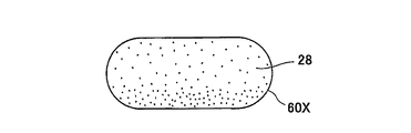
図3は、粒状物28が添加された従来のトウバンド60Xの搬送方向から見た鉛直断面図である。図3は、一例として、粒状物の添加位置から開繊室の出口までの間の部分が水平になるように気体開繊装置を配置し、添加位置から開繊室の出口へ向けてトウバンド60Xを水平方向に搬送すると共に、添加位置においてトウバンド60Xに上方から粒状物28を添加した場合のトウバンド60Xの鉛直断面を示している。図3に示すように、トウバンド60Xの内部では、開繊室において開繊されるトウバンド60Xに対して、トウバンド60Xの搬送方向に垂直な一方向(鉛直方向)に重力が粒状物28に作用したことで、粒状物28がトウバンド60Xの下側に偏在している。
[Toe band and absorbent articles]
FIG. 3 is a vertical cross-sectional view of the conventional tow band 60X to which the granular material 28 is added as viewed from the transport direction. In FIG. 3, as an example, the gas opening device is arranged so that the portion between the addition position of the granular material and the outlet of the opening chamber is horizontal, and the tow band 60X is arranged from the addition position toward the outlet of the opening chamber. Is shown in the horizontal direction, and the vertical cross section of the tow band 60X is shown when the granular material 28 is added to the toe band 60X from above at the addition position. As shown in FIG. 3, inside the tow band 60X, gravity acts on the granules 28 in one direction (vertical direction) perpendicular to the transport direction of the tow band 60X with respect to the tow band 60X opened in the fiber opening chamber. As a result, the granules 28 are unevenly distributed under the toe band 60X.

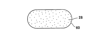
図4は、図1の滞留部20を通過し且つ搬送ロール対11より上流側を搬送されるトウバンド60の搬送方向Pから見た鉛直断面図である。図4に示すように、これに対して製造装置1では、添加位置Nから開繊室43aの出口までの間において、トウバンド60の搬送方向Pに垂直な方向に重力が粒状物28に作用するのが抑制されたことにより、トウバンド60の内部に粒状物28が均一に分散されて配置されている。 FIG. 4 is a vertical cross-sectional view of the toe band 60 that passes through the retention portion 20 of FIG. 1 and is conveyed upstream of the transfer roll pair 11 as viewed from the transfer direction P. On the other hand, as shown in FIG. 4, in the manufacturing apparatus 1, gravity acts on the granular material 28 in the direction perpendicular to the transport direction P of the tow band 60 between the addition position N and the outlet of the fiber opening chamber 43a. The granules 28 are uniformly dispersed and arranged inside the toe band 60 due to the suppression of the above.

また製造装置1では、全ての開繊ロール対(本実施形態では、第1開繊ロール対7と第2開繊ロール対8)によりトウバンド60を開繊した後、気体開繊装置9によりトウバンド60を開繊したことにより、トウバンド60が開繊されて嵩高に膨らんだ状態を維持しつつ、トウバンド60の繊維間隙に均一に分散した所定量の粒状物28が、トウバンド60の複数本の繊維に保持されている。 Further, in the manufacturing apparatus 1, after the tow band 60 is opened by all the opening roll pairs (in the present embodiment, the first opening roll pair 7 and the second opening roll pair 8), the toe band is opened by the gas opening roll pair 9. By opening the fibers 60, a predetermined amount of granules 28 uniformly dispersed in the fiber gaps of the toe band 60 are formed into a plurality of fibers of the toe band 60 while maintaining the state in which the toe band 60 is opened and bulged in a bulky manner. It is held in.

図5は、図1の製造装置1により製造された吸収性物品62の搬送方向Pから見た鉛直断面図である。図5に示すように、製造装置1では、トウバンド60の内部に粒状物28が均一に分散されて配置された吸収体61の下方にバックシート63を配置し、上方にトップシート64を配置したことにより、幅方向に均一な吸水性能を有する吸収性物品62が製造される。 FIG. 5 is a vertical cross-sectional view of the absorbent article 62 manufactured by the manufacturing apparatus 1 of FIG. 1 as viewed from the transport direction P. As shown in FIG. 5, in the manufacturing apparatus 1, the back sheet 63 is arranged below the absorber 61 in which the granules 28 are uniformly dispersed and arranged inside the toe band 60, and the top sheet 64 is arranged above. As a result, the absorbent article 62 having a uniform water absorption performance in the width direction is manufactured.

吸収性物品62は、吸水性能が部分的にばらつくのが防止され、幅方向に均一な吸水性能を発揮できるため、吸収性物品62の全体において良好に吸水できる。また吸収体61の内部では、粒状物28が偏在していないので、粒状物28の偏在位置で水分が集中して吸水されることで吸収性物品62の表面がべたつきを生じるのが防止され、吸収性物品62の吸水後の触感を良好に保つことができる。 Since the absorbent article 62 is prevented from partially varying in water absorption performance and can exhibit uniform water absorption performance in the width direction, the absorbent article 62 can absorb water satisfactorily as a whole. Further, since the granules 28 are not unevenly distributed inside the absorber 61, it is possible to prevent the surface of the absorbent article 62 from becoming sticky due to the concentrated water absorption at the uneven distribution positions of the granules 28. The tactile sensation of the absorbent article 62 after absorbing water can be kept good.

以上に説明したように、製造装置1によれば、添加位置Nの下方に開繊室43aの出口が配置された状態で、添加位置Nから開繊室43aの出口へ向けて、トウバンド60が上方から下方へ搬送されると共に、開繊室43aの出口よりも上流側に位置する添加位置Nにおいて、粒状物28がトウバンド60に添加されるので、開繊室43aでトウバンド60が開繊される際、粒状物28に対して、搬送方向Pに垂直な方向に重力が作用するのが抑制される。これにより、トウバンド60の内部において重力により粒状物28が偏在するのが抑制され、トウバンド60の内部に粒状物28を均一に分散して配置し易くできる。 As described above, according to the manufacturing apparatus 1, the toe band 60 is provided from the addition position N toward the outlet of the fiber opening chamber 43a in a state where the outlet of the fiber opening chamber 43a is arranged below the addition position N. The tow band 60 is opened in the fiber opening chamber 43a because the granular material 28 is added to the tow band 60 at the addition position N located on the upstream side of the outlet of the fiber opening chamber 43a while being transported from the upper side to the lower side. At that time, the action of gravity on the granular material 28 in the direction perpendicular to the transport direction P is suppressed. As a result, the uneven distribution of the granules 28 due to gravity is suppressed inside the toe band 60, and the granules 28 can be easily dispersed and arranged inside the toe band 60.

また、添加位置Nの真下に開繊室43aの出口が配置された状態で、添加位置Nから開繊室43aの出口へ向けて、トウバンド60が鉛直方向に搬送されるので、トウバンド60の内部において重力により粒状物が偏在するのが更に抑制され、トウバンド60の内部に粒状物28を一層均一に分散して配置し易くできる。 Further, since the toe band 60 is conveyed in the vertical direction from the addition position N to the outlet of the fiber opening chamber 43a in a state where the outlet of the fiber opening chamber 43a is arranged directly below the addition position N, the inside of the tow band 60 The uneven distribution of the granules due to gravity is further suppressed, and the granules 28 can be more uniformly dispersed and arranged inside the tow band 60.

また添加位置Nは、開繊室43aの入口よりも上流側に位置しているので、開繊室43aにおいてトウバンド60を開繊しながら、効率よく粒状物28をトウバンド60の繊維間隙に分散して配置し易くできる。 Further, since the addition position N is located on the upstream side of the entrance of the fiber opening chamber 43a, the granules 28 are efficiently dispersed in the fiber gaps of the tow band 60 while opening the tow band 60 in the fiber opening chamber 43a. Can be easily placed.

また気体開繊装置9が、滞留部20を有し、開繊室43aの出口を通過したトウバンド60が、滞留部20を鉛直方向に通過するので、トウバンド60の内部に粒状物28が均一に分散されて配置された状態を維持しながら、トウバンド60の繊維密度を滞留部20で高めることができる。 Further, since the gas opening device 9 has the retaining portion 20, the tow band 60 that has passed through the outlet of the fiber opening chamber 43a passes through the retaining portion 20 in the vertical direction, so that the granules 28 are uniformly contained inside the tow band 60. The fiber density of the tow band 60 can be increased by the retention portion 20 while maintaining the dispersed and arranged state.

また気体開繊装置9が、搬送路43に気体Gを導入する気体導入口35aを有し、添加位置Nが、気体導入口35aよりも上流側に位置しているので、気体導入口35aから搬送路43に導入される気体Gによって、添加位置Nから導入される粒状物28を、トウバンド60の内部に良好に分散して配置できる。 Further, since the gas opening device 9 has a gas introduction port 35a for introducing the gas G into the transport path 43 and the addition position N is located on the upstream side of the gas introduction port 35a, the gas introduction port 35a The gas G introduced into the transport path 43 allows the granules 28 introduced from the addition position N to be well dispersed and arranged inside the tow band 60.

また製造装置1は、気体開繊装置9よりも上流側において、トウバンド60を周面に接触させて開繊する複数対の開繊ロール対7、8を備えているので、複数対の開繊ロール対7、8により開繊されたトウバンド60を、気体開繊装置9により、更に嵩高に絡み合わせながら開繊でき、繊維間隙を広げたトウバンド60の内部に、粒状物28を均一に分散し易くできる。以下、第2実施形態について、第1実施形態の差異を中心に説明する。 Further, since the manufacturing apparatus 1 includes a plurality of pairs of spread fiber pairs 7 and 8 in which the tow band 60 is brought into contact with the peripheral surface to spread the fibers on the upstream side of the gas fiber spreader 9, the plurality of pairs of fiber spreaders are spread. The tow band 60 opened by the roll pairs 7 and 8 can be opened by the gas opening device 9 while being further entangled with each other, and the granules 28 are uniformly dispersed inside the tow band 60 having widened fiber gaps. It can be made easy. Hereinafter, the second embodiment will be described focusing on the differences of the first embodiment.

(第2実施形態)
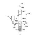
図6は、第2実施形態に係る気体開繊装置109と添加装置110との側面図である。図6に示すように、添加装置110の供給管122は、気体開繊装置109の開繊成型部119の側部に接続されている。供給管122の下流端部は、搬送路143内に露出している。
(Second Embodiment)
FIG. 6 is a side view of the gas spreading device 109 and the adding device 110 according to the second embodiment. As shown in FIG. 6, the supply pipe 122 of the addition device 110 is connected to the side portion of the fiber opening molding portion 119 of the gas fiber opening device 109. The downstream end of the supply pipe 122 is exposed in the transport path 143.

添加装置110は、供給管122の途中に設けられた補助ジェット発生部145を有する。補助ジェット発生部145は、外部から導入される気体Gによりジェットを発生させ、このジェットにより、粒状物28のトウバンド60への添加を補助する。 The addition device 110 has an auxiliary jet generator 145 provided in the middle of the supply pipe 122. The auxiliary jet generation unit 145 generates a jet by the gas G introduced from the outside, and the jet assists the addition of the granular material 28 to the tow band 60.

添加装置110は、補助ジェット発生部145により粒状物28を搬送路143に強制的に送り込むことで、ジェット発生部118の内部を流れる別のジェットにより粒状物28が逆流するのを防止する。これにより添加装置110は、搬送路143が含む開繊室143aにおいて、搬送路143を搬送されるトウバンド60に粒状物28を添加する。 The addition device 110 forcibly sends the granular material 28 into the transport path 143 by the auxiliary jet generating unit 145, thereby preventing the granular material 28 from flowing back due to another jet flowing inside the jet generating unit 118. As a result, the addition device 110 adds the granular material 28 to the tow band 60 transported through the transport path 143 in the fiber opening chamber 143a included in the transport path 143.

このような気体開繊装置109と添加装置110とを用いても、第1実施形態の吸収性物品62と同様の吸収性物品を得ることができる。なお、第2実施形態では、添加位置Nが開繊成型部119の内部に位置しているため、気体開繊装置109の添加位置Nよりも上側の部分(例えば導入部117とジェット発生部118)は、一例として、各長手方向が水平方向に延びるように配置されていてもよい。 Even if such a gas spreading device 109 and an adding device 110 are used, an absorbent article similar to the absorbent article 62 of the first embodiment can be obtained. In the second embodiment, since the addition position N is located inside the fiber opening molding portion 119, the portions above the addition position N of the gas fiber opening device 109 (for example, the introduction unit 117 and the jet generation unit 118) ), As an example, may be arranged so that each longitudinal direction extends in the horizontal direction.

(確認試験)
製造装置1を用いて、粒状物28が添加され且つ気体開繊装置9を通過し、搬送ロール対11よりも上流側を搬送されるトウバンド(以下、成型品と称する)を実施例として製造した。
(Confirmation test)
Using the manufacturing apparatus 1, a tow band (hereinafter referred to as a molded product) to which the granular material 28 is added, passes through the gas spreading apparatus 9, and is transported upstream of the transport roll pair 11 is manufactured as an example. ..

気体開繊装置9の開繊室43aの出口から添加装置10のガイド部34の上端位置までの間の部分を水平に配置し、且つ、トウバンドに上方から粒状物28を添加するように変更した以外は実施例と同様の設定条件により、製造装置1を用いて、比較例1の成型品を製造した。 The portion between the outlet of the opening chamber 43a of the gas opening device 9 and the upper end position of the guide portion 34 of the adding device 10 was arranged horizontally, and the toe band was changed to add the granular material 28 from above. The molded product of Comparative Example 1 was manufactured using the manufacturing apparatus 1 under the same setting conditions as in the examples except for the above.

気体開繊装置9の開繊室43aの出口から添加装置10のガイド部34の上端位置まで間の部分を水平に配置し、且つ、滞留部20と搬送ロール対11との間に添加位置Nを設定して、トウバンドに上方から粒状物28を添加するように変更した以外は実施例と同様の設定条件により、製造装置1を用いて、比較例2の成型品を製造した。 The portion between the outlet of the opening chamber 43a of the gas opening device 9 and the upper end position of the guide portion 34 of the adding device 10 is horizontally arranged, and the addition position N is provided between the retaining portion 20 and the transfer roll pair 11. The molded product of Comparative Example 2 was manufactured using the manufacturing apparatus 1 under the same setting conditions as in the example except that the tow band was changed to add the granular material 28 from above.

実施例、比較例1、及び比較例2においては、搬送方向寸法1m当たりのトウバンドの重量を5.7g、搬送方向寸法1m当たりのトウバンドに対する粒状物量を3.3g、成型品の幅寸法を40mm、成型品の厚み寸法を25mmにそれぞれ設定した。 In Examples, Comparative Example 1 and Comparative Example 2, the weight of the toe band per 1 m of the transport direction dimension is 5.7 g, the amount of granules with respect to the tow band per 1 m of the transport direction dimension is 3.3 g, and the width dimension of the molded product is 40 mm. , The thickness dimension of the molded product was set to 25 mm, respectively.

成型品の幅方向における粒状物28の分布を調べるため、搬送方向寸法が10cmとなるように切断した実施例、比較例1、及び比較例2の成型品を、更に幅方向中央で切断し、幅方向の一方側と他方側とに含まれる粒状物量の割合(重量%)を算出した。 In order to investigate the distribution of the granules 28 in the width direction of the molded product, the molded products of Examples, Comparative Example 1 and Comparative Example 2 cut so as to have a transport direction dimension of 10 cm were further cut at the center in the width direction. The ratio (% by weight) of the amount of granules contained on one side and the other side in the width direction was calculated.

また、成型品の深さ(厚み)方向における粒状物28の分布を調べるため、搬送方向寸法が2cmとなるように切断した実施例、比較例1、及び比較例2の成型品を、更に鉛直方向中央で上下に切断し、上側部分と下側部分とに含まれる粒状物量の割合(重量%)を算出した。 Further, in order to investigate the distribution of the granules 28 in the depth (thickness) direction of the molded product, the molded products of Examples, Comparative Example 1 and Comparative Example 2 cut so as to have a transport direction dimension of 2 cm were further vertical. It was cut vertically at the center of the direction, and the ratio (% by weight) of the amount of granules contained in the upper portion and the lower portion was calculated.

また、以下の方法により成型品の上部から脱落する粒状物量の割合を調べた。搬送方向寸法が30cmとなるように切断した実施例、比較例1、及び比較例2の成型品を上下逆にして配置したときの動作前後において、成型品に含まれる粒状物量を測定し、成型品を上下逆に配置したときに成型品の上部から脱落した粒状物量の割合(重量%)を算出した。 In addition, the ratio of the amount of granules falling off from the upper part of the molded product was examined by the following method. Before and after the operation when the molded products of Examples, Comparative Example 1 and Comparative Example 2 cut so as to have a transport direction dimension of 30 cm are arranged upside down, the amount of granules contained in the molded product is measured and molded. The ratio (% by weight) of the amount of granules that fell off from the upper part of the molded product when the product was arranged upside down was calculated.

また、以下の方法により成型品の下部から脱落する粒状物量の割合を調べた。滞留部の下流端部から一定距離だけ下流側に離隔した位置において、搬送方向Pの寸法が30cmとなるように切断した実施例、比較例1、及び比較例2の成型品に含まれる粒状物量を測定することにより、添加位置Nで添加された後に成型品の下部から脱落した粒状物量の割合(重量%)を算出した。これらの算出結果を表1に示す。 In addition, the ratio of the amount of granules falling off from the lower part of the molded product was examined by the following method. Amount of granules contained in the molded products of Examples, Comparative Example 1 and Comparative Example 2 cut so that the dimension of the transport direction P is 30 cm at a position separated downstream from the downstream end of the retention portion by a certain distance. The ratio (% by weight) of the amount of granules that fell off from the lower part of the molded product after being added at the addition position N was calculated by measuring. The results of these calculations are shown in Table 1.

Figure 0006830786
Figure 0006830786

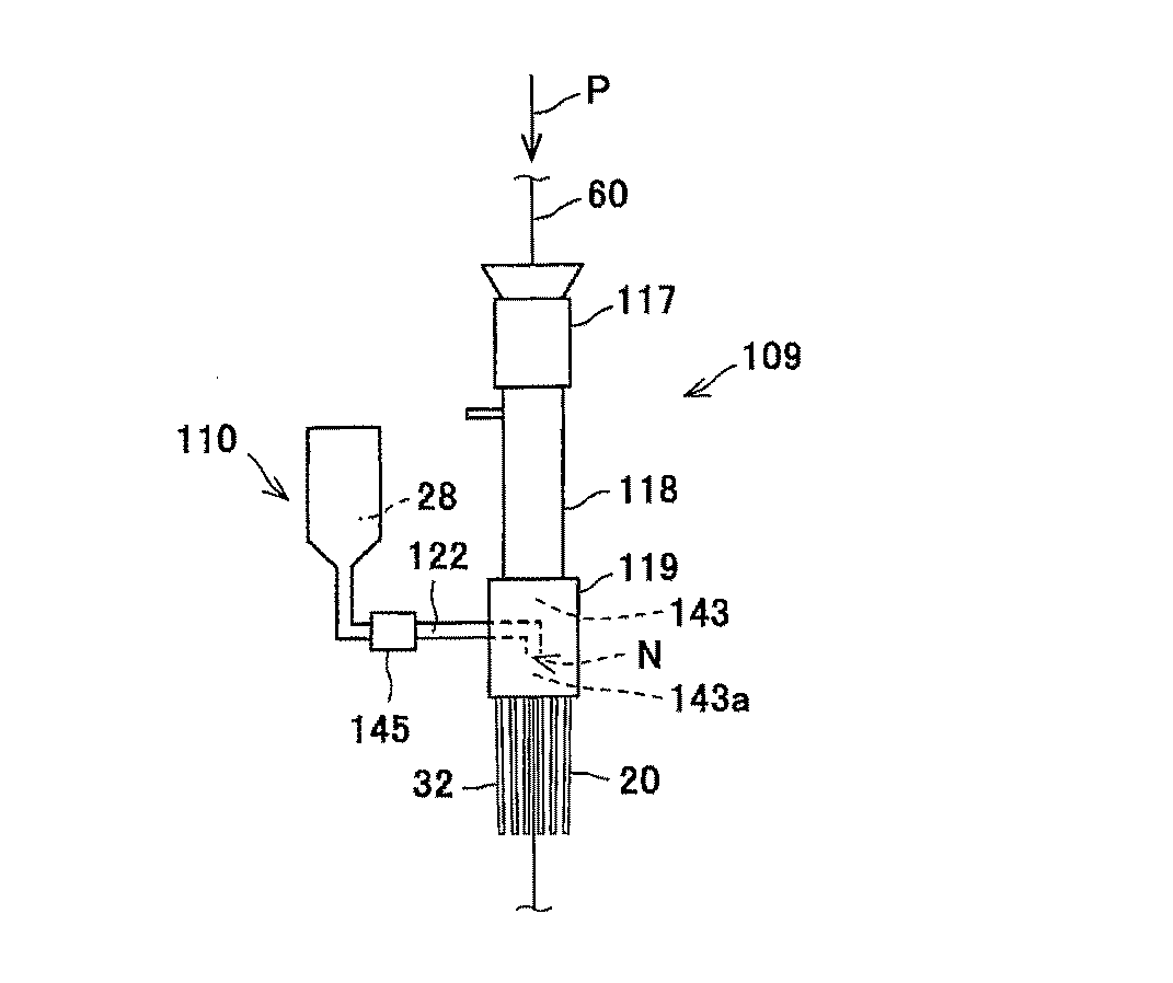
表1に示すように、実施例、比較例1、及び比較例2では、成型品の幅方向での粒状物の分布については差が見られなかった。しかしながら、比較例1及び2は、成型品の深さ方向における粒状物28の分布が、実施例に比べて不均一であり、成型品の内部で、粒状物28が成型品の上側又は下側に偏在していることが分かった。 As shown in Table 1, in Example, Comparative Example 1, and Comparative Example 2, no difference was observed in the distribution of granules in the width direction of the molded product. However, in Comparative Examples 1 and 2, the distribution of the granules 28 in the depth direction of the molded product is non-uniform as compared with the examples, and the granules 28 are on the upper side or the lower side of the molded product inside the molded product. It turned out that it is unevenly distributed in.

具体的に比較例1では、成型品の下側に粒状物28が偏在していた。この理由として、比較例1では、トウバンド60に上方から添加された粒状物28が、トウバンド60の内部を重力により移動し、トウバンド60の下側に偏在したことが考えられる。 Specifically, in Comparative Example 1, the granules 28 were unevenly distributed on the lower side of the molded product. It is considered that the reason for this is that in Comparative Example 1, the granules 28 added to the toe band 60 from above moved by gravity inside the toe band 60 and were unevenly distributed under the toe band 60.

また比較例2では、成型品の上側に粒状物28が偏在していた。この理由として、比較例2では、粒状物28が開繊され且つ成型されたトウバンド60に上方から粒状物28が添加されたため、粒状物28がトウバンド60の内部に分散されにくく、粒状物28がトウバンド60の上側に偏在したことが考えられる。 Further, in Comparative Example 2, the granules 28 were unevenly distributed on the upper side of the molded product. The reason for this is that in Comparative Example 2, since the granular material 28 was added from above to the tow band 60 in which the granular material 28 was opened and molded, the granular material 28 was difficult to be dispersed inside the toe band 60, and the granular material 28 was formed. It is considered that the tow band 60 was unevenly distributed on the upper side.

実施例では、比較例1及び2に比べて、トウバンド60の内部に粒状物28が均一に分散して配置されていた。この理由として、実施例では、開繊室43aの出口と添加位置Nとの間において、トウバンド60が鉛直方向に搬送されたことにより、開繊室43aの入口よりも上流側に位置する添加位置Nからトウバンド60に添加された粒状物28が、搬送方向Pに垂直な方向にトウバンド60の内部を重力により移動するのが抑制されながら、開繊されるトウバンド60の繊維間隙に均一に分散して配置されたことが考えられる。 In the examples, the granules 28 were uniformly dispersed and arranged inside the tow band 60 as compared with Comparative Examples 1 and 2. The reason for this is that, in the embodiment, the tow band 60 is transported in the vertical direction between the outlet of the fiber opening chamber 43a and the addition position N, so that the addition position located upstream of the inlet of the fiber opening chamber 43a. Granules 28 added to the toe band 60 from N are uniformly dispersed in the fiber gaps of the tow band 60 to be opened while being suppressed from moving inside the toe band 60 by gravity in the direction perpendicular to the transport direction P. It is possible that they were placed.

また実施例では、成型品の上部からの粒状物28の脱落と、成型品の下部からの粒状物28の脱落とが、比較例1と略同等に抑制されることが分かった。この理由として、実施例では、開繊室43aの出口よりも上流側において、トウバンド60に粒状物28を添加したことにより、トウバンド60を開繊しながらトウバンド60の内部に粒状物28が均一に分散して配置され、粒状物28が複数本の繊維により保持されたことが考えられる。 Further, in the examples, it was found that the shedding of the granules 28 from the upper part of the molded product and the shedding of the granules 28 from the lower part of the molded product were suppressed substantially in the same manner as in Comparative Example 1. The reason for this is that, in the examples, by adding the granules 28 to the toe band 60 on the upstream side of the outlet of the fiber opening chamber 43a, the granules 28 are uniformly dispersed inside the tow band 60 while opening the tow band 60. It is considered that the particles 28 were dispersed and arranged, and the granules 28 were held by a plurality of fibers.

また比較例2では、成型品の上部からの粒状物28の脱落が、実施例及び比較例1に比べて非常に多いことが分かった。これは、粒状物28の多くが、トウバンド60の上側に堆積して配置されたことにより、トウバンド60の複数本の繊維に保持されていなかったため、成型品を上下逆に配置したことで、粒状物28が容易にトウバンド60から脱落したことが考えられる。 Further, in Comparative Example 2, it was found that the amount of the granular material 28 falling off from the upper part of the molded product was much larger than that in Example and Comparative Example 1. This is because most of the granules 28 were deposited and arranged on the upper side of the toe band 60 and were not held by the plurality of fibers of the toe band 60. Therefore, the molded product was arranged upside down, so that the granules 28 were arranged upside down. It is considered that the object 28 easily fell off from the toe band 60.

本発明は、各実施形態に限定されるものではなく、本発明の趣旨を逸脱しない範囲で、その構成及び方法を変更、追加、又は削除できる。各実施形態は、互いに任意に組み合わせてもよく、例えば1つの実施形態中の一部の構成または方法を、他の実施形態に適用してもよい。 The present invention is not limited to each embodiment, and its configuration and method can be changed, added, or deleted without departing from the spirit of the present invention. The embodiments may be arbitrarily combined with each other, for example, some configurations or methods in one embodiment may be applied to other embodiments.

以上のように本発明によれば、内部に吸水性の粒状物が配置された吸収体を備える吸収性物品を製造する場合において、吸収体の内部に粒状物を均一に分散して配置できる優れた効果を有する。従って、この効果の意義を発揮できる吸収性物品製造装置及び吸収性物品の製造方法として、広く適用すると有益である。 As described above, according to the present invention, in the case of producing an absorbent article having an absorber in which water-absorbent granules are arranged, the granules can be uniformly dispersed and arranged inside the absorber. Has an effect. Therefore, it is beneficial to widely apply it as an absorbent article manufacturing apparatus and a method for manufacturing an absorbent article capable of exerting the significance of this effect.

G 気体
N 添加装置
P 搬送方向
1 吸収性物品製造装置
7 第1開繊ロール対(開繊ロール対)
8 第2開繊ロール対(開繊ロール対)
9、109 気体開繊装置
10、110 添加装置
19a トウバンド導入口(開繊室の入口)
19b トウバンド排出口(開繊室の出口)
20 滞留部
35a 気体導入口
43、143 搬送路
43a、143a 開繊室
43b 開繊室の出口
60 トウバンド(トウ)
G Gas N Addition device P Transport direction 1 Absorbent article manufacturing device 7 1st spread fiber pair (open fiber roll pair)
8 Second spread fiber pair (open fiber roll pair)
9,109 Gas fiber opening device 10,110 Addition device 19a Tow band introduction port (entrance of fiber opening chamber)
19b Toe band outlet (exit of opening chamber)
20 Retention part 35a Gas introduction port 43, 143 Transport path 43a, 143a Fiber opening chamber 43b Exit of fiber opening chamber 60 Toe band (toe)

Claims (12)

搬送されるトウを気体で開繊する開繊室を含む搬送路が形成された気体開繊装置と、
前記開繊室の出口よりも前記トウの搬送方向の上流側に位置する添加位置において、吸水性の粒状物を前記トウに添加する添加装置と、を備え、
前記添加位置の下方に前記出口が配置された状態で、前記添加位置から前記出口へ向けて、前記トウが、鉛直方向又は鉛直方向に対して0°以上30°以内の範囲の値の角度で上方から下方へ搬送される、吸収性物品製造装置。
A gas fiber opening device having a transport path including a fiber opening chamber for opening the tow to be transported with gas,
An addition device for adding water-absorbing granules to the tow at an addition position located upstream of the outlet of the fiber opening chamber in the transport direction of the tow is provided.
With the outlet arranged below the addition position, the toe is at an angle in the range of 0 ° or more and within 30 ° with respect to the vertical direction or the vertical direction from the addition position toward the outlet. Absorbent article manufacturing equipment that is transported from top to bottom.
前記添加位置は、前記搬送路の流路断面の内方に位置している、請求項1に記載の吸収性物品製造装置。 The absorbent article manufacturing apparatus according to claim 1, wherein the addition position is located inside the cross section of the flow path of the transport path . 前記添加位置は、前記開繊室の入口よりも前記上流側に位置している、請求項1又は2に記載の吸収性物品製造装置。 The absorbent article manufacturing apparatus according to claim 1 or 2, wherein the addition position is located on the upstream side of the entrance of the fiber opening chamber. 前記気体開繊装置は、前記出口を通過した前記トウを一時的に滞留させる滞留部を有し、
前記出口を通過した前記トウが、前記滞留部を鉛直方向に通過する、請求項1〜3のいずれか1項に記載の吸収性物品製造装置。
The gas spreading device has a retention portion for temporarily retaining the tow that has passed through the outlet.
The absorbent article manufacturing apparatus according to any one of claims 1 to 3, wherein the tow that has passed through the outlet passes through the stagnant portion in the vertical direction.
前記気体開繊装置は、前記搬送路に前記気体を導入する気体導入口を有し、
前記添加位置は、前記気体導入口よりも前記上流側に位置している、請求項1〜4のいずれか1項に記載の吸収性物品製造装置。
The gas opening device has a gas introduction port for introducing the gas into the transport path.
The absorbent article manufacturing apparatus according to any one of claims 1 to 4, wherein the addition position is located on the upstream side of the gas introduction port.
前記気体開繊装置よりも前記上流側において、前記トウを周面に接触させて開繊する複数対の開繊ロール対を備える、請求項1〜5のいずれか1項に記載の吸収性物品製造装置。 The absorbent article according to any one of claims 1 to 5, further comprising a plurality of pairs of opening rolls for opening the fibers by bringing the toe into contact with the peripheral surface on the upstream side of the gas opening device. Manufacturing equipment. 搬送されるトウを気体で開繊する開繊室を含む搬送路が形成された気体開繊装置と、吸水性の粒状物を前記トウに添加する添加装置とを用い、
前記開繊室の出口よりも前記トウの搬送方向の上流側に位置し且つ前記粒状物を前記トウに添加する添加位置の下方に前記出口が配置されるように前記添加装置を配置した状態で、前記添加位置から前記出口へ向けて、前記トウを、鉛直方向又は鉛直方向に対して0°以上30°以内の範囲の値の角度で上方から下方へ搬送する、吸収性物品の製造方法。
Using a gas fiber opening device in which a transport path including a fiber opening chamber for opening the conveyed tow with gas was formed, and an addition device for adding water-absorbing granules to the tow.
It was placed the addition device such that the outlet is arranged to position and且previous SL particulates on the upstream side in the transport direction of the tow under the feed point to be added to the tow than the outlet of the open繊室Manufacture of an absorbent article in which the tow is transported from above to below at an angle in the range of 0 ° or more and within 30 ° with respect to the vertical direction or the vertical direction from the addition position to the outlet. Method.
前記添加位置を、前記搬送路の流路断面の内方に位置させる、請求項7に記載の吸収性物品の製造方法。 The method for producing an absorbent article according to claim 7, wherein the addition position is located inside the cross section of the flow path of the transport path . 前記添加位置を、前記開繊室の入口よりも前記上流側に位置させる、請求項7又は8に記載の吸収性物品の製造方法。 The method for producing an absorbent article according to claim 7 or 8, wherein the addition position is located on the upstream side of the entrance of the fiber opening chamber. 前記出口を通過した前記トウを一時的に滞留させる滞留部を有する前記気体開繊装置を用い、
前記出口を通過した前記トウを、前記滞留部に鉛直方向に通過させる、請求項7〜9のいずれか1項に記載の吸収性物品の製造方法。
Using the gas spreading device having a retention portion for temporarily retaining the tow that has passed through the outlet,
The method for producing an absorbent article according to any one of claims 7 to 9, wherein the tow that has passed through the outlet is passed through the retention portion in the vertical direction.
前記搬送路に前記気体を導入する気体導入口を有する前記気体開繊装置を用い、
前記添加位置を、前記気体導入口よりも前記上流側に位置させる、請求項7〜10のいずれか1項に記載の吸収性物品の製造方法。
Using the gas spreading device having a gas introduction port for introducing the gas into the transport path,
The method for producing an absorbent article according to any one of claims 7 to 10, wherein the addition position is located on the upstream side of the gas introduction port.
前記気体開繊装置よりも前記上流側において、前記トウを複数対の開繊ロール対の周面に接触させて開繊する、請求項7〜11のいずれか1項に記載の吸収性物品の製造方法。 The absorbent article according to any one of claims 7 to 11, wherein the tow is brought into contact with the peripheral surfaces of a plurality of pairs of opening rolls to open the fibers on the upstream side of the gas opening device. Production method.
JP2016197345A 2016-10-05 2016-10-05 Absorbent article manufacturing equipment and method of manufacturing absorbent articles Active JP6830786B2 (en)

Priority Applications (1)

Application Number Priority Date Filing Date Title
JP2016197345A JP6830786B2 (en) 2016-10-05 2016-10-05 Absorbent article manufacturing equipment and method of manufacturing absorbent articles

Applications Claiming Priority (1)

Application Number Priority Date Filing Date Title
JP2016197345A JP6830786B2 (en) 2016-10-05 2016-10-05 Absorbent article manufacturing equipment and method of manufacturing absorbent articles

Publications (2)

Publication Number Publication Date
JP2018059240A JP2018059240A (en) 2018-04-12
JP6830786B2 true JP6830786B2 (en) 2021-02-17

Family

ID=61907543

Family Applications (1)

Application Number Title Priority Date Filing Date
JP2016197345A Active JP6830786B2 (en) 2016-10-05 2016-10-05 Absorbent article manufacturing equipment and method of manufacturing absorbent articles

Country Status (1)

Country Link
JP (1) JP6830786B2 (en)

Also Published As

Publication number Publication date
JP2018059240A (en) 2018-04-12

Similar Documents

Publication Publication Date Title
US6048489A (en) Absorbent products, and apparatus and method for producing the same
US8887359B2 (en) Apparatus for manufacturing opening matter of long-sized fiber tow
JP5283857B2 (en) Fiber sheet manufacturing apparatus and manufacturing method
JP6761685B2 (en) Absorbent article manufacturing equipment and method of manufacturing absorbent articles
JP6646383B2 (en) Tow opening apparatus, fiber sheet manufacturing apparatus using the same, and fiber sheet manufacturing method
EP0330675A1 (en) Method and apparatus for depositing moisture-absorbent material in a substrate.
US20100048393A1 (en) Solid Particle Controlled Dispersing Nozzle and Process
JP6793570B2 (en) Absorbent article manufacturing equipment and method of manufacturing absorbent articles
JP6830786B2 (en) Absorbent article manufacturing equipment and method of manufacturing absorbent articles
JP6398006B2 (en) Tow opening device, fiber sheet manufacturing device using the same, and fiber sheet manufacturing method
US10166698B2 (en) Crushing mill for crushing fibrous material and a unit for forming absorbent cores in a machine which makes absorbent sanitary articles
JP6765924B2 (en) Absorbent article manufacturing equipment and method of manufacturing absorbent articles
JP6830785B2 (en) Tow spreading device, absorbent article manufacturing device, and method for manufacturing absorbent article
JP6053548B2 (en) Absorber manufacturing apparatus and manufacturing method
CN105050560B (en) Absorb hygienic object and the machine for manufacturing the object
JP6646384B2 (en) Tow opening apparatus, fiber sheet manufacturing apparatus using the same, and fiber sheet manufacturing method
JP6653632B2 (en) Absorbent article manufacturing apparatus and method for manufacturing absorbent article
JP2014117558A (en) Device and method of producing water absorber
JP7121480B2 (en) ABSORBENT ARTICLE MANUFACTURING METHOD, ABSORBENT ARTICLE MANUFACTURER, ABSORBENT ARTICLE, AND ABSORBENT
WO2023162217A1 (en) Additive adding unit, filler element manufacturing device equipped with said adding unit, additive adding method, and filler element manufacturing method using said adding method
WO2018142627A1 (en) Tow opening device, fiber sheet manufacturing device using same, and fiber sheet manufacturing method
WO2020105077A1 (en) Method for producing absorbent article, apparatus for producing absorbent article, absorbent article, and absorber
CN106473863B (en) Production device of absorbent for breast pad, absorbent produced by same and breast pad
WO2021079400A1 (en) Absorbent article
WO2019224988A1 (en) Absorbent body and absorbent article

Legal Events

Date Code Title Description
A621 Written request for application examination

Free format text: JAPANESE INTERMEDIATE CODE: A621

Effective date: 20190819

A977 Report on retrieval

Free format text: JAPANESE INTERMEDIATE CODE: A971007

Effective date: 20200626

A131 Notification of reasons for refusal

Free format text: JAPANESE INTERMEDIATE CODE: A131

Effective date: 20200811

A521 Written amendment

Free format text: JAPANESE INTERMEDIATE CODE: A523

Effective date: 20200902

TRDD Decision of grant or rejection written
A01 Written decision to grant a patent or to grant a registration (utility model)

Free format text: JAPANESE INTERMEDIATE CODE: A01

Effective date: 20210119

A61 First payment of annual fees (during grant procedure)

Free format text: JAPANESE INTERMEDIATE CODE: A61

Effective date: 20210127

R150 Certificate of patent or registration of utility model

Ref document number: 6830786

Country of ref document: JP

Free format text: JAPANESE INTERMEDIATE CODE: R150