JP6830692B2 - Fluid measurement methods, measuring devices and measuring systems - Google Patents
Fluid measurement methods, measuring devices and measuring systems Download PDFInfo
- Publication number
- JP6830692B2 JP6830692B2 JP2019526683A JP2019526683A JP6830692B2 JP 6830692 B2 JP6830692 B2 JP 6830692B2 JP 2019526683 A JP2019526683 A JP 2019526683A JP 2019526683 A JP2019526683 A JP 2019526683A JP 6830692 B2 JP6830692 B2 JP 6830692B2
- Authority
- JP
- Japan
- Prior art keywords
- image
- light
- fluid
- mutation
- wavelength region
- Prior art date
- Legal status (The legal status is an assumption and is not a legal conclusion. Google has not performed a legal analysis and makes no representation as to the accuracy of the status listed.)
- Active
Links
- 239000012530 fluid Substances 0.000 title claims description 336
- 238000000691 measurement method Methods 0.000 title claims description 18
- 150000001875 compounds Chemical class 0.000 claims description 105
- 230000035772 mutation Effects 0.000 claims description 88
- 238000002835 absorbance Methods 0.000 claims description 66
- 238000005286 illumination Methods 0.000 claims description 66
- 230000001678 irradiating effect Effects 0.000 claims description 57
- 238000005259 measurement Methods 0.000 claims description 50
- 238000004364 calculation method Methods 0.000 claims description 45
- 238000012545 processing Methods 0.000 claims description 43
- 238000003384 imaging method Methods 0.000 claims description 41
- 238000000034 method Methods 0.000 claims description 37
- 238000000926 separation method Methods 0.000 claims description 23
- 238000003860 storage Methods 0.000 claims description 23
- 238000010521 absorption reaction Methods 0.000 claims description 18
- 238000000059 patterning Methods 0.000 claims description 14
- 230000008033 biological extinction Effects 0.000 claims description 8
- 238000002703 mutagenesis Methods 0.000 claims 6
- 231100000350 mutagenesis Toxicity 0.000 claims 6
- 238000012800 visualization Methods 0.000 description 54
- 238000009826 distribution Methods 0.000 description 33
- 230000033001 locomotion Effects 0.000 description 17
- 239000010408 film Substances 0.000 description 16
- 239000003921 oil Substances 0.000 description 16
- 239000012085 test solution Substances 0.000 description 14
- 230000000052 comparative effect Effects 0.000 description 13
- 230000005540 biological transmission Effects 0.000 description 10
- 238000005461 lubrication Methods 0.000 description 9
- 238000002474 experimental method Methods 0.000 description 8
- 239000000126 substance Substances 0.000 description 8
- 239000002184 metal Substances 0.000 description 7
- IJGRMHOSHXDMSA-UHFFFAOYSA-N Atomic nitrogen Chemical compound N#N IJGRMHOSHXDMSA-UHFFFAOYSA-N 0.000 description 6
- 239000010687 lubricating oil Substances 0.000 description 6
- 239000000203 mixture Substances 0.000 description 6
- 239000010705 motor oil Substances 0.000 description 6
- 230000006870 function Effects 0.000 description 5
- 230000031700 light absorption Effects 0.000 description 5
- 238000004040 coloring Methods 0.000 description 4
- 238000002845 discoloration Methods 0.000 description 4
- 239000005357 flat glass Substances 0.000 description 4
- 238000002360 preparation method Methods 0.000 description 4
- 238000004611 spectroscopical analysis Methods 0.000 description 4
- PSXPTGAEJZYNFI-UHFFFAOYSA-N 1',3',3'-trimethyl-6-nitrospiro[chromene-2,2'-indole] Chemical compound O1C2=CC=C([N+]([O-])=O)C=C2C=CC21C(C)(C)C1=CC=CC=C1N2C PSXPTGAEJZYNFI-UHFFFAOYSA-N 0.000 description 3
- 238000000862 absorption spectrum Methods 0.000 description 3
- 239000000314 lubricant Substances 0.000 description 3
- 229910052757 nitrogen Inorganic materials 0.000 description 3
- 238000002834 transmittance Methods 0.000 description 3
- 238000006243 chemical reaction Methods 0.000 description 2
- 230000007423 decrease Effects 0.000 description 2
- 238000010586 diagram Methods 0.000 description 2
- 239000010696 ester oil Substances 0.000 description 2
- 239000011521 glass Substances 0.000 description 2
- 239000007788 liquid Substances 0.000 description 2
- 230000002441 reversible effect Effects 0.000 description 2
- 239000010409 thin film Substances 0.000 description 2
- 238000004458 analytical method Methods 0.000 description 1
- 230000000694 effects Effects 0.000 description 1
- 238000005516 engineering process Methods 0.000 description 1
- 238000009434 installation Methods 0.000 description 1
- 230000007774 longterm Effects 0.000 description 1
- DZVCFNFOPIZQKX-LTHRDKTGSA-M merocyanine Chemical group [Na+].O=C1N(CCCC)C(=O)N(CCCC)C(=O)C1=C\C=C\C=C/1N(CCCS([O-])(=O)=O)C2=CC=CC=C2O\1 DZVCFNFOPIZQKX-LTHRDKTGSA-M 0.000 description 1
- 239000012780 transparent material Substances 0.000 description 1
Images


Classifications
-
- G—PHYSICS
- G01—MEASURING; TESTING
- G01N—INVESTIGATING OR ANALYSING MATERIALS BY DETERMINING THEIR CHEMICAL OR PHYSICAL PROPERTIES
- G01N21/00—Investigating or analysing materials by the use of optical means, i.e. using sub-millimetre waves, infrared, visible or ultraviolet light
- G01N21/84—Systems specially adapted for particular applications
- G01N21/85—Investigating moving fluids or granular solids
-
- G—PHYSICS
- G01—MEASURING; TESTING
- G01B—MEASURING LENGTH, THICKNESS OR SIMILAR LINEAR DIMENSIONS; MEASURING ANGLES; MEASURING AREAS; MEASURING IRREGULARITIES OF SURFACES OR CONTOURS
- G01B11/00—Measuring arrangements characterised by the use of optical techniques
- G01B11/02—Measuring arrangements characterised by the use of optical techniques for measuring length, width or thickness
- G01B11/06—Measuring arrangements characterised by the use of optical techniques for measuring length, width or thickness for measuring thickness ; e.g. of sheet material
-
- G—PHYSICS
- G01—MEASURING; TESTING
- G01N—INVESTIGATING OR ANALYSING MATERIALS BY DETERMINING THEIR CHEMICAL OR PHYSICAL PROPERTIES
- G01N21/00—Investigating or analysing materials by the use of optical means, i.e. using sub-millimetre waves, infrared, visible or ultraviolet light
- G01N21/17—Systems in which incident light is modified in accordance with the properties of the material investigated
- G01N21/25—Colour; Spectral properties, i.e. comparison of effect of material on the light at two or more different wavelengths or wavelength bands
- G01N21/31—Investigating relative effect of material at wavelengths characteristic of specific elements or molecules, e.g. atomic absorption spectrometry
- G01N21/314—Investigating relative effect of material at wavelengths characteristic of specific elements or molecules, e.g. atomic absorption spectrometry with comparison of measurements at specific and non-specific wavelengths
-
- G—PHYSICS
- G01—MEASURING; TESTING
- G01N—INVESTIGATING OR ANALYSING MATERIALS BY DETERMINING THEIR CHEMICAL OR PHYSICAL PROPERTIES
- G01N21/00—Investigating or analysing materials by the use of optical means, i.e. using sub-millimetre waves, infrared, visible or ultraviolet light
- G01N21/17—Systems in which incident light is modified in accordance with the properties of the material investigated
- G01N21/25—Colour; Spectral properties, i.e. comparison of effect of material on the light at two or more different wavelengths or wavelength bands
- G01N21/31—Investigating relative effect of material at wavelengths characteristic of specific elements or molecules, e.g. atomic absorption spectrometry
- G01N21/33—Investigating relative effect of material at wavelengths characteristic of specific elements or molecules, e.g. atomic absorption spectrometry using ultraviolet light
-
- G—PHYSICS
- G01—MEASURING; TESTING
- G01N—INVESTIGATING OR ANALYSING MATERIALS BY DETERMINING THEIR CHEMICAL OR PHYSICAL PROPERTIES
- G01N21/00—Investigating or analysing materials by the use of optical means, i.e. using sub-millimetre waves, infrared, visible or ultraviolet light
- G01N21/62—Systems in which the material investigated is excited whereby it emits light or causes a change in wavelength of the incident light
- G01N21/63—Systems in which the material investigated is excited whereby it emits light or causes a change in wavelength of the incident light optically excited
- G01N21/631—Systems in which the material investigated is excited whereby it emits light or causes a change in wavelength of the incident light optically excited using photolysis and investigating photolysed fragments
-
- G—PHYSICS
- G01—MEASURING; TESTING
- G01P—MEASURING LINEAR OR ANGULAR SPEED, ACCELERATION, DECELERATION, OR SHOCK; INDICATING PRESENCE, ABSENCE, OR DIRECTION, OF MOVEMENT
- G01P13/00—Indicating or recording presence, absence, or direction, of movement
- G01P13/0006—Indicating or recording presence, absence, or direction, of movement of fluids or of granulous or powder-like substances
-
- G—PHYSICS
- G01—MEASURING; TESTING
- G01N—INVESTIGATING OR ANALYSING MATERIALS BY DETERMINING THEIR CHEMICAL OR PHYSICAL PROPERTIES
- G01N21/00—Investigating or analysing materials by the use of optical means, i.e. using sub-millimetre waves, infrared, visible or ultraviolet light
- G01N21/62—Systems in which the material investigated is excited whereby it emits light or causes a change in wavelength of the incident light
- G01N21/63—Systems in which the material investigated is excited whereby it emits light or causes a change in wavelength of the incident light optically excited
- G01N2021/634—Photochromic material analysis
Description
本発明は、流体の計測方法、計測装置および計測システムに関する。 The present invention relates to a fluid measuring method, a measuring device and a measuring system.
一般に、機械的な運動を行う場合、互いに摺動する部材間に薄膜を形成して動作を滑らかにする潤滑剤等の流体を介在させている。例えば、ピストン、シリンダ、すべり軸受などでは機械的に円滑に作動させることが要求され、すべり面には潤滑油が入れられる。ピストン、シリンダ、すべり軸受などを円滑に作動するためには、形状、境界面の間隔、潤滑油の量や質などの最適化が必要になる。 Generally, when mechanical movement is performed, a fluid such as a lubricant is interposed by forming a thin film between members that slide with each other to smooth the movement. For example, pistons, cylinders, slide bearings, etc. are required to operate smoothly mechanically, and lubricating oil is put into the slide surface. In order to operate pistons, cylinders, slide bearings, etc. smoothly, it is necessary to optimize the shape, the spacing between interface surfaces, and the quantity and quality of lubricating oil.
従来、ピストン−シリンダ間の油膜の潤滑状態を把握するために、フォトクロミック反応を生じる物質を用いて油膜内流れの可視化を実現する技術が提案されている(非特許文献1参照)。
フォトクロミック反応とは、紫外光などの光を特定の物質に照射することにより当該物質の色素の分子構造を変化させ、それに伴って吸収スペクトルが変化する現象である。つまり、色素の分子構造を変化する前の物質は吸収スペクトルが無いため、光を照射しても着色されないが、色素の分子構造が変化した物質は特定の波長領域の光を照射すると、光を吸収して着色する。Conventionally, in order to grasp the lubrication state of the oil film between the piston and the cylinder, a technique for visualizing the flow in the oil film by using a substance that causes a photochromic reaction has been proposed (see Non-Patent Document 1).
The photochromic reaction is a phenomenon in which a specific substance is irradiated with light such as ultraviolet light to change the molecular structure of the dye of the substance, and the absorption spectrum changes accordingly. In other words, a substance before changing the molecular structure of the dye does not have an absorption spectrum, so it is not colored even when irradiated with light, but a substance with a changed molecular structure of the dye emits light when irradiated with light in a specific wavelength region. Absorb and color.
非特許文献1に記載される技術では、潤滑油(エンジンオイル)にフォトクロミック化合物を含有し、フォトクロミック化合物の色素の分子構造を変化させるための光(例えば、紫外光)をエンジンオイルに照射し、色素の分子構造が変化した部分を時間経過と共に撮影する。ここで、潤滑油の撮影は、観測用の照明光(例えば、白色光)を照射した状態でカメラを用いて行われる。
In the technique described in
観測用の照明光を測定部のエンジンオイルに当てることによりエンジンオイルからの反射光(厳密にはエンジンオイルを透過し背面のエンジンから反射してくる光)を得られるが、この反射光は、フォトクロミズムにより吸収スペクトルが変化した影響で、吸収された波長域では反射光強度が低下する。その為、時間経過と共に反射光強度の結果を撮影し、撮影した撮影画像を解析することでエンジンオイルが流れる様子が分かる。
ここで、光の吸収量を表す指標として吸光度があり、撮影画像の解析は吸光度を用いて行われる。吸光度は以下の式で求められる。By shining the illumination light for observation on the engine oil of the measuring part, the reflected light from the engine oil (strictly speaking, the light that passes through the engine oil and is reflected from the engine on the back) can be obtained. Due to the change in the absorption spectrum due to photochromism, the reflected light intensity decreases in the absorbed wavelength range. Therefore, the result of the reflected light intensity is photographed with the passage of time, and the state of the engine oil flowing can be understood by analyzing the photographed image.
Here, there is absorbance as an index showing the amount of light absorbed, and the analysis of the captured image is performed using the absorbance. The absorbance is calculated by the following formula.
着色前後の光強度(撮影画像の強度値)を
Ibefore ・・・着色前の光強度
Iafter ・・・着色後の光強度
とすると、吸光度Asの計算式は、以下の式となる。なお、LOGは常用対数である。
As=−LOG(Iafter/Ibefore)When coloring around the light intensity (intensity value of the captured image) and I before · · · before the colored light intensity I after · · · light intensity after coloring, calculation of absorbance A s can be expressed as the following formula. LOG is a common logarithm.
A s = -LOG (I after / I before)
非特許文献1に記載される技術によれば、油膜の潤滑状態を把握することが可能であるが、駆動部の動き、油膜表面の動き、気泡の分布等による油膜の変動がノイズとして含まれ、詳細な油膜の流れを把握することができず、油膜のより詳細な潤滑状態を観測したいという要望がある。その為には、フォトクロミズムを従来技術よりも鮮明に撮影・解析する必要がある。
しかし、非特許文献1には、このような要望を満たす具体的な技術内容について、記載も示唆もされていない。According to the technique described in Non-Patent
However, Non-Patent
本発明はかかる点に鑑みてなされたものであって、動く物体中、変化する場のような測定環境でも測定対象物を計測することができる計測方法、計測装置および計測システムを提供することを課題とする。
ここで、フォトクロミズムを生じさせる変異発生光を照射することによって、特定の波長領域の吸収量が変化したフォトクロミック化合物のことを、変異フォトクロミック化合物と定義する。また、測定対象物の計測には、例えば、時間経過に伴う流れの可視化や特定時刻における厚さの測定などが含まれる。The present invention has been made in view of this point, and provides a measuring method, a measuring device, and a measuring system capable of measuring an object to be measured even in a measuring environment such as a moving object or a changing field. Make it an issue.
Here, a photochromic compound in which the amount of absorption in a specific wavelength region is changed by irradiating with mutation-generating light that causes photochromism is defined as a mutant photochromic compound. Further, the measurement of the object to be measured includes, for example, visualization of the flow with the passage of time and measurement of the thickness at a specific time.
前記課題を解決するために、本発明の一態様による計測方法は、流体の計測方法であって、変異発生光を照射することで光の吸収量が変化するフォトクロミック化合物を前記流体に溶解する準備工程と、フォトクロミズムを生じさせる変異発生光を前記流体に照射する変異発生光照射工程と、前記変異発生光を照射した後の前記流体の画像を撮影する変異後画像撮影工程と、前記変異後画像撮影工程の後で行う画像処理工程とを有する。In order to solve the above problems, the measurement method according to one aspect of the present invention is a fluid measurement method, in which a photochromic compound whose light absorption amount changes by irradiating with mutation-generating light is prepared to be dissolved in the fluid. A step, a mutation-generating light irradiation step of irradiating the fluid with mutation-generating light that causes photochromism, a post-mutation imaging step of photographing the fluid image after irradiation with the mutation-generating light, and the post-mutation image. It has an image processing step performed after the photographing step.
前記変異後画像撮影工程では、変異発生光が照射されることによって光の吸収量が変化する第1の波長領域の第1の光を用いて前記流体を撮影することで第1画像を生成し、また、前記吸収量が全くまたは殆ど変化しない第2の波長領域の第2の光を用いて、前記第1画像の撮影と同時刻の前記流体を撮影した第2画像を生成する。In the post-mutation imaging step, a first image is generated by photographing the fluid using the first light in the first wavelength region in which the amount of light absorbed changes when the mutation-generating light is irradiated. In addition, the second light in the second wavelength region in which the absorption amount does not change at all or hardly changes is used to generate a second image in which the fluid is photographed at the same time as the first image is photographed.
前記画像処理工程では、前記第1画像および前記第2画像を用いて第3画像を生成する。In the image processing step, a third image is generated using the first image and the second image.
例えば、第3画像は、第1画像と第2画像との比を取ってから対数を算出することにより生成される。具体的には、前記画像処理工程では、次式(1)を用いて各画素における吸光度A1を計算し、各画素の計算結果を2次元パターン化することで前記第3画像を生成するのがよい。なお、LOGは常用対数である。
A1=−LOG(I11/I21)・・・式(1)
ここで、「I11」は、前記変異後画像撮影工程で撮影した第1画像を構成する画素の光強度である。「I21」は、前記変異後画像撮影工程で撮影した第2画像を構成する画素の光強度である。For example, the third image is generated by taking the ratio of the first image and the second image and then calculating the logarithm. Specifically, in the image processing step, the absorbance A1 in each pixel is calculated using the following equation (1), and the calculation result of each pixel is two-dimensionally patterned to generate the third image. Good. LOG is a common logarithm.
A1 = -LOG (I1 1 / I2 1 ) ... Equation (1)
Here, "I 1 1 " is the light intensity of the pixels constituting the first image taken in the post-mutation image taking step. “I 2 1 ” is the light intensity of the pixels constituting the second image taken in the post-mutation image taking step.
前記課題を解決するために、本発明の一態様による計測方法は、流体の計測方法であって、変異発生光を照射することで光の吸収量が変化するフォトクロミック化合物を前記流体に溶解する準備工程と、フォトクロミズムを生じさせる変異発生光を前記流体に照射する変異発生光照射工程と、前記変異発生光を照射した後の前記流体の画像を撮影する変異後画像撮影工程と、前記変異後画像撮影工程の後で行う流体厚さ算出工程とを有する。In order to solve the above-mentioned problems, the measurement method according to one aspect of the present invention is a fluid measurement method, in which a photochromic compound whose light absorption amount changes by irradiating with mutation-generating light is prepared to be dissolved in the fluid. A step, a mutation-generating light irradiation step of irradiating the fluid with mutation-generating light that causes photochromism, a post-mutation imaging step of photographing the fluid image after irradiation with the mutation-generating light, and the post-mutation image. It has a fluid thickness calculation step performed after the photographing step.
前記変異後画像撮影工程では、変異発生光が照射されることによって光の吸収量が変化する第1の波長領域の第1の光を用いて前記流体を撮影することで第1画像を生成し、また、前記吸収量が全くまたは殆ど変化しない第2の波長領域の第2の光を用いて、前記第1画像の撮影と同時刻の前記流体を撮影した第2画像を生成する。In the post-mutation imaging step, a first image is generated by photographing the fluid using the first light in the first wavelength region in which the amount of light absorbed changes when the mutation-generating light is irradiated. In addition, the second light in the second wavelength region in which the absorption amount does not change at all or hardly changes is used to generate a second image in which the fluid is photographed at the same time as the first image is photographed.
前記流体厚さ算出工程では、前記第1画像および前記第2画像を用いて前記流体の厚さを算出する。In the fluid thickness calculation step, the thickness of the fluid is calculated using the first image and the second image.
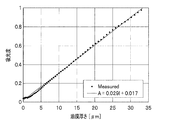
例えば、流体の厚さは、吸光度と厚さとの関係(例えば、比例)により算出する。具体的には、前記流体厚さ算出工程では、次式(1)を用いて変異発生光が照射された領域の画素における吸光度A1を計算し、
A1=−LOG(I11/I21)・・・式(1)
さらに、次式(3)を用いて流体厚さlを計算するのがよい。
l=A1/μ ・・・式(3)
ここで、「I11」は、前記変異後画像撮影工程で撮影した第1画像を構成する画素の光強度である。「I21」は、前記変異後画像撮影工程で撮影した第2画像を構成する画素の光強度である。「μ」は、前記フォトクロミック化合物を溶解した後の前記流体の吸光係数である。For example, the thickness of a fluid is calculated by the relationship between the absorbance and the thickness (for example, proportionality). Specifically, in the fluid thickness calculation step, the absorbance A1 in the pixel in the region irradiated with the mutation-generating light is calculated using the following equation (1).
A1 = -LOG (I1 1 / I2 1 ) ... Equation (1)
Further, it is preferable to calculate the fluid thickness l using the following equation (3).
l = A1 / μ ・ ・ ・ Equation (3)
Here, "I 1 1 " is the light intensity of the pixels constituting the first image taken in the post-mutation image taking step. “I 2 1 ” is the light intensity of the pixels constituting the second image taken in the post-mutation image taking step. “Μ” is the extinction coefficient of the fluid after the photochromic compound is dissolved.
また、本発明の一態様による計測装置は、フォトクロミズムを生じさせる変異発生光が照射されることによって特定の波長領域の光の吸収量が変化するフォトクロミック化合物が溶解された流体の流れを可視化する計測装置である。
この計測装置は、前記吸収量が変化する第1の波長領域の第1の光を用いて前記流体を撮影した第1画像を記憶する第1画像記憶手段と、前記吸収量が全くまたは殆ど変化しない第2の波長領域の第2の光を用いて、前記第1画像の撮影と同時刻の前記流体を撮影した第2画像を記憶する第2画像記憶手段と、前記第1画像および前記第2画像を用いて前記流体の流れを可視化した第3画像を生成する画像処理手段と、を備える。
前記画像処理手段は、前記変異発生光を照射した後の前記流体を撮影した前記第1画像および前記第2画像を用いて第3画像を生成する。In addition, the measuring device according to one aspect of the present invention visualizes the flow of a fluid in which a photochromic compound in which the amount of light absorbed in a specific wavelength region changes when irradiated with mutation-generating light that causes photochromism. It is a device.
This measuring device has a first image storage means for storing a first image obtained by photographing the fluid using the first light in the first wavelength region in which the absorption amount changes, and the absorption amount changes completely or almost. A second image storage means for storing a second image in which the fluid is photographed at the same time as the first image is photographed by using the second light in the second wavelength region, the first image, and the first image. It is provided with an image processing means for generating a third image in which the flow of the fluid is visualized using two images.
The image processing means generates a third image using the first image and the second image obtained by photographing the fluid after irradiating the mutation generating light.
例えば、第3画像は、第1画像と第2画像との比を取ってから対数を算出することにより生成される。具体的には、前記画像処理手段は、次式(1)を用いて各画素における吸光度A1を計算し、各画素の計算結果を2次元パターン化することで前記第3画像を生成するのがよい。なお、LOGは常用対数である。
A1=−LOG(I11/I21)・・・式(1)
ここで、「I11」は、前記変異発生光を照射した後の第1画像を構成する画素の光強度である。「I21」は、前記変異発生光を照射した後の第2画像を構成する画素の光強度である。For example, the third image is generated by taking the ratio of the first image and the second image and then calculating the logarithm. Specifically, the image processing means calculates the absorbance A1 in each pixel using the following equation (1), and generates the third image by two-dimensionally patterning the calculation result of each pixel. Good. LOG is a common logarithm.
A1 = -LOG (I1 1 / I2 1 ) ... Equation (1)
Here, "I 1 1 " is the light intensity of the pixels constituting the first image after irradiating the mutation-generating light. “I 2 1 ” is the light intensity of the pixels constituting the second image after irradiating the mutation-generating light.
また、本発明の一態様による計測装置は、フォトクロミズムを生じさせる変異発生光が照射されることによって特定の波長領域の光の吸収量が変化するフォトクロミック化合物が溶解された流体の厚さを測定する計測装置である。
この計測装置は、前記吸収量が変化する第1の波長領域の第1の光を用いて前記流体を撮影した第1画像を記憶する第1画像記憶手段と、前記吸収量が全くまたは殆ど変化しない第2の波長領域の第2の光を用いて、前記第1画像の撮影と同時刻の前記流体を撮影した第2画像を記憶する第2画像記憶手段と、前記第1画像および前記第2画像を用いて前記流体の厚さを算出する流体厚さ算出手段と、を備える。
前記流体厚さ算出手段は、前記変異発生光を照射した後の前記流体を撮影した前記第1画像および前記第2画像を用いて前記流体の厚さを算出する。In addition, the measuring device according to one aspect of the present invention measures the thickness of a fluid in which a photochromic compound in which the amount of light absorbed in a specific wavelength region changes when irradiated with mutation-generating light that causes photochromism. It is a measuring device.
This measuring device has a first image storage means for storing a first image of the fluid taken by using the first light in a first wavelength region in which the absorption amount changes, and the absorption amount changes completely or almost. A second image storage means for storing a second image of the fluid taken at the same time as the first image was taken using the second light in the second wavelength region, and the first image and the first image. (2) A fluid thickness calculating means for calculating the thickness of the fluid using an image is provided.
The fluid thickness calculating means calculates the thickness of the fluid by using the first image and the second image of the fluid after irradiating the mutation generating light.
例えば、流体の厚さは、吸光度と厚さとの関係(例えば、比例)により算出する。具体的には、前記流体厚さ算出手段は、次式(1)を用いて変異発生光が照射された領域の画素における吸光度A1を計算し、
A1=−LOG(I11/I21)・・・式(1)
さらに、次式(3)を用いて流体厚さlを計算するのがよい。
l=A1/μ ・・・式(3)
ここで、「I11」は、前記変異発生光を照射した後の第1画像を構成する画素の光強度である。「I21」は、前記変異発生光を照射した後の第2画像を構成する画素の光強度である。「μ」は、前記フォトクロミック化合物を溶解した後の前記流体の吸光係数である。For example, the thickness of a fluid is calculated by the relationship between the absorbance and the thickness (for example, proportionality). Specifically, the fluid thickness calculating means calculates the absorbance A1 in the pixel of the region irradiated with the mutation-generating light by using the following equation (1).
A1 = -LOG (I1 1 / I2 1 ) ... Equation (1)
Further, it is preferable to calculate the fluid thickness l using the following equation (3).
l = A1 / μ ・ ・ ・ Equation (3)
Here, "I 1 1 " is the light intensity of the pixels constituting the first image after irradiating the mutation-generating light. “I 2 1 ” is the light intensity of the pixels constituting the second image after irradiating the mutation-generating light. “Μ” is the extinction coefficient of the fluid after the photochromic compound is dissolved.
このような工程を有する計測方法は、光の吸収量が変化する第1の波長領域を用いて流体の第1画像を撮影し、また、吸光度が全くまたは殆ど変化しない第2の波長領域を用いて流体の第2画像を撮影する工程を備えている。また、このような構成を備える計測装置は、光の吸収量が変化する第1の波長領域を用いて流体を撮影した第1画像を記憶し、また、吸光度が全くまたは殆ど変化しない第2の波長領域を用いて流体を撮影した第2画像を記憶する。
第1の波長領域は変異フォトクロミック化合物の光の吸収量が変化する領域なので、第1画像では流体内の変異フォトクロミック化合物が着色された状態で写し出される。ここで、流体の状況(例えば、油膜厚さ)が変化した場合に、第1画像に写し出される変異フォトクロミック化合物の分布と同時に、装置の汚れや傷等による変色や、流体表面の動き、気泡の分布等の流体の状況の変化の影響が同時にノイズとして反映される。
第2の波長領域は変異フォトクロミック化合物であっても光の吸収量が全くまたは殆ど変化しない領域なので、第2画像では流体内の変異フォトクロミック化合物が着色されずに、装置の汚れや傷等による変色や、流体表面の動き、気泡の分布等の流体の状況が写し出される。
ここで、同時刻の第1画像および第2画像には、同じ状態の流体表面の動き、気泡の分布等の流体の状況が写し出されるので、第1画像および第2画像を用いた第3画像では、流体の表面の動き、気泡の分布等の流体の状況の変化の影響等の様々なノイズが低減され、着色された変異フォトクロミック化合物の分布の変化がより鮮明に写し出される。また、同様に、第1画像および第2画像を用いて算出した流体厚さlは、様々なノイズの影響が低減されることにより正確な値となる。In the measurement method having such a step, the first image of the fluid is taken using the first wavelength region in which the amount of light absorption changes, and the second wavelength region in which the absorbance changes at all or hardly changes is used. It is provided with a step of taking a second image of the fluid. Further, the measuring device having such a configuration stores a first image in which a fluid is photographed using a first wavelength region in which the amount of light absorbed changes, and a second image in which the absorbance does not change at all or hardly changes. A second image in which the fluid is photographed using the wavelength region is stored.
Since the first wavelength region is a region in which the amount of light absorbed by the mutant photochromic compound changes, the mutant photochromic compound in the fluid is projected in a colored state in the first image. Here, when the fluid condition (for example, oil film thickness) changes, at the same time as the distribution of the mutant photochromic compound projected on the first image, discoloration due to dirt or scratches on the device, movement of the fluid surface, air bubbles, etc. The influence of changes in fluid conditions such as distribution is reflected as noise at the same time.
Since the second wavelength region is a region in which the amount of light absorbed does not change at all or hardly changes even if the mutant photochromic compound is used, the mutant photochromic compound in the fluid is not colored in the second image and is discolored due to stains or scratches on the device. The state of the fluid, such as the movement of the fluid surface and the distribution of bubbles, is projected.
Here, since the fluid conditions such as the movement of the fluid surface and the distribution of bubbles in the same state are projected on the first image and the second image at the same time, the third image using the first image and the second image is used. Then, various noises such as the movement of the surface of the fluid and the influence of changes in the fluid condition such as the distribution of bubbles are reduced, and the change in the distribution of the colored mutant photochromic compound is more clearly projected. Similarly, the fluid thickness l calculated using the first image and the second image becomes an accurate value by reducing the influence of various noises.
また、計測方法は、前記変異発生光照射工程の前で、前記変異発生光を照射する前の前記流体の第1画像および第2画像を撮影する変異前画像撮影工程を有し、前記画像処理工程では、次式(2)を用いて各画素における吸光度Aを計算し、各画素の計算結果を2次元パターン化することで前記第3画像を生成するのがよい。なお、LOGは常用対数である。
A=−LOG(I11/I21)−(−LOG(I10/I20))・・・式(2)
ここで、「I10」は、前記変異前画像撮影工程で撮影した第1画像を構成する画素の光強度である。「I20」は、前記変異前画像撮影工程で撮影した第2画像を構成する画素の光強度である。Further, the measurement method includes a pre-mutation image capturing step of capturing a first image and a second image of the fluid before irradiating the mutation generating light before the mutation generating light irradiation step, and the image processing. In the step, it is preferable to calculate the absorbance A in each pixel using the following equation (2) and generate the third image by two-dimensionally patterning the calculation result of each pixel. LOG is a common logarithm.
A = -LOG (I1 1 / I2 1 )-(-LOG (I1 0 / I2 0 )) ... Equation (2)
Here, "I1 0" is the light intensity of the pixels constituting the first image captured by the mutant pre-imaging process. “I2 0 ” is the light intensity of the pixels constituting the second image taken in the pre-mutation image taking step.
また、計測方法は、前記変異発生光照射工程の前で、前記変異発生光を照射する前の前記流体の第1画像および第2画像を撮影する変異前画像撮影工程を有し、前記流体厚さ算出工程では、次式(2)を用いて変異発生光が照射された領域の画素における吸光度Aを計算し、
A=−LOG(I11/I21)−(−LOG(I10/I20))・・・式(2)
さらに、次式(4)を用いて流体厚さlを計算するのがよい。
l=A/μ ・・・式(4)
ここで、「I10」は、前記変異前画像撮影工程で撮影した第1画像を構成する画素の光強度である。「I20」は、前記変異前画像撮影工程で撮影した第2画像を構成する画素の光強度である。Further, the measurement method includes a pre-mutation imaging step of capturing a first image and a second image of the fluid before irradiating the mutation-generating light before the mutation-generating light irradiation step, and the fluid thickness. In the calculation step, the absorbance A in the pixel in the region irradiated with the mutation-generating light is calculated using the following equation (2).
A = -LOG (I1 1 / I2 1 )-(-LOG (I1 0 / I2 0 )) ... Equation (2)
Further, it is preferable to calculate the fluid thickness l using the following equation (4).
l = A / μ ・ ・ ・ Equation (4)
Here, "I1 0" is the light intensity of the pixels constituting the first image captured by the mutant pre-imaging process. “I2 0 ” is the light intensity of the pixels constituting the second image taken in the pre-mutation image taking step.
また、計測装置は、前記画像処理手段が、次式(2)を用いて各画素における吸光度Aを計算し、各画素の計算結果を2次元パターン化することで前記第3画像を生成するのがよい。なお、LOGは常用対数である。
A=−LOG(I11/I21)−(−LOG(I10/I20))・・・式(2)
ここで、「I10」は、前記変異発生光を照射する前の第1画像を構成する画素の光強度である。「I20」は、前記変異発生光を照射する前の第2画像を構成する画素の光強度である。Further, in the measuring device, the image processing means calculates the absorbance A in each pixel using the following equation (2), and the calculation result of each pixel is two-dimensionally patterned to generate the third image. Is good. LOG is a common logarithm.
A = -LOG (I1 1 / I2 1 )-(-LOG (I1 0 / I2 0 )) ... Equation (2)
Here, "I1 0" is the light intensity of the pixels constituting the first image before irradiating the mutations generated light. “I2 0 ” is the light intensity of the pixels constituting the second image before irradiating the mutation-generating light.
また、計測装置は、前記流体厚さ算出手段が、次式(2)を用いて変異発生光が照射された領域の画素における吸光度Aを計算し、
A=−LOG(I11/I21)−(−LOG(I10/I20))・・・式(2)
さらに、次式(4)を用いて流体厚さlを計算するのがよい。
l=A/μ ・・・式(4)
ここで、「I10」は、前記変異発生光を照射する前の第1画像を構成する画素の光強度である。「I20」は、前記変異発生光を照射する前の第2画像を構成する画素の光強度である。Further, in the measuring device, the fluid thickness calculating means calculates the absorbance A in the pixel of the region irradiated with the mutation-generating light by using the following equation (2).
A = -LOG (I1 1 / I2 1 )-(-LOG (I1 0 / I2 0 )) ... Equation (2)
Further, it is preferable to calculate the fluid thickness l using the following equation (4).
l = A / μ ・ ・ ・ Equation (4)
Here, "I1 0" is the light intensity of the pixels constituting the first image before irradiating the mutations generated light. “I2 0 ” is the light intensity of the pixels constituting the second image before irradiating the mutation-generating light.
このような工程を有する計測方法、および、このような構成を備える計測装置は、前記変異発生光を照射する前の流体を撮影した第1画像および第2画像と、前記変異発生光を照射した後の流体を撮影した第1画像および第2画像とを用いて第3画像を生成し、または、流体厚さlを計算する。
ここで、第1の波長領域の光、第2の波長領域の光によって反射率が異なる部分がある場合(例えば、エッジ部)や、2つの光源を使う等によって第1の波長領域の光と第2の波長領域の光の強度分布が異なる場合(例えば、第1画像上部が明るく、第2画像下部が明るい等の場合)であっても、変異発生光を照射する前の第1画像と変異発生光を照射した後の第1画像および変異発生光を照射する前の第2画像と変異発生光を照射した後の第2画像には、ほぼ同じ状態の第1の波長領域の光および第2の波長領域の光によって流体の状況が写し出される。
その為、第3画像には、装置の汚れや傷等による変色の影響の軽減だけではなく、第1の波長領域の光、第2の波長領域の光の波長の違いによって反射率が異なる部分や、第1の波長領域の光と第2の波長領域の光の強度分布が異なることによって生ずる光による様々なノイズが同時に低減され、着色された変異フォトクロミック化合物の分布の変化がより鮮明に写し出される。これにより、動く物体中や変化する場のような流体の状況が変化し易い測定環境でも、流体の流れをより鮮明に可視化することができる。また、同様に、流体厚さlは、これらのノイズの影響が低減されることにより正確な値となる。A measuring method having such a step and a measuring device having such a configuration irradiated the first image and the second image of the fluid before irradiating the mutation-generating light, and the mutation-generating light. A third image is generated using the first image and the second image obtained by photographing the subsequent fluid, or the fluid thickness l is calculated.
Here, when there is a portion where the reflectance differs depending on the light in the first wavelength region and the light in the second wavelength region (for example, the edge portion), or when two light sources are used, the light in the first wavelength region and the light in the first wavelength region are used. Even if the light intensity distribution in the second wavelength region is different (for example, the upper part of the first image is bright, the lower part of the second image is bright, etc.), it is different from the first image before the mutation-generated light is irradiated. The first image after irradiation with the mutation-generating light, the second image before irradiation with the mutation-generating light, and the second image after irradiation with the mutation-generating light show the light in the first wavelength region in almost the same state and the light in the first wavelength region. The light in the second wavelength region reflects the state of the fluid.
Therefore, in the third image, not only the influence of discoloration due to dirt or scratches on the device is reduced, but also the reflectance differs depending on the difference in wavelength between the light in the first wavelength region and the light in the second wavelength region. In addition, various noises caused by light caused by different intensity distributions of light in the first wavelength region and light in the second wavelength region are simultaneously reduced, and changes in the distribution of colored mutant photochromic compounds are projected more clearly. Is done. As a result, the flow of the fluid can be visualized more clearly even in a measurement environment where the condition of the fluid is likely to change, such as in a moving object or a changing field. Similarly, the fluid thickness l becomes an accurate value by reducing the influence of these noises.
また、本発明の一態様による計測システムは、前記計測装置と、前記第1の光および前記第2の光を含む照明光を前記流体に照射する照明手段と、前記流体を透過した後の前記照明光を前記第1の波長領域の第1の光と前記第2の波長領域の第2の光とに分離する分離手段と、を備える。
また、計測システムは、前記分離手段により分離された前記第1の光を撮像し、前記第1画像を生成する第1撮像手段と、前記分離手段により分離された前記第2の光を撮像し、前記第2画像を生成する第2撮像手段と、を備える。
前記照明手段は、前記第1撮像手段および前記第2撮像手段が撮影を行うタイミングに前記照明光を照射するタイミングを合わせたパルス光として前記照明光を照射する。Further, the measurement system according to one aspect of the present invention includes the measuring device, an illuminating means for irradiating the fluid with illumination light including the first light and the second light, and the said after passing through the fluid. A separation means for separating the illumination light into the first light in the first wavelength region and the second light in the second wavelength region is provided.
Further, the measurement system captures the first light separated by the separation means and images the first imaging means for generating the first image and the second light separated by the separation means. The second imaging means for generating the second image is provided.
The illumination means irradiates the illumination light as pulsed light in which the timing of irradiating the illumination light is matched with the timing at which the first imaging means and the second imaging means take a picture.
このような構成を備える計測システムは、撮影を行うタイミングで照明光を照射するので、撮影を行わない時間帯に照明光を照射せずにすむ。その為、照明光の光や熱による変異フォトクロミック化合物の変異を減衰させる期間を短くすることができ、また撮影に十分な照明光量を照射できるので、流体の長時間の流れを鮮明に可視化することができる。 Since the measurement system having such a configuration irradiates the illumination light at the timing of shooting, it is not necessary to irradiate the illumination light during the time when the shooting is not performed. Therefore, it is possible to shorten the period for attenuating the mutation of the mutant photochromic compound due to the light or heat of the illumination light, and it is possible to irradiate a sufficient amount of illumination light for photographing, so that the long-term flow of the fluid can be clearly visualized. Can be done.
また、計測システムは、前記変異発生光を照射する変異発生光源を備えるのがよい。この変異発生光源が、前記流体の流れを可視化する領域を決定するために光のサイズを任意の大きさに調整する機能と、前記変異発生光を前記流体の任意の位置に照射する機能とを備え、前記任意の大きさの前記変異発生光を前記流体の流れを可視化する前記任意の位置にパルス光として前記流体に照射する。 Further, the measurement system may include a mutation generation light source that irradiates the mutation generation light. The mutation-generating light source has a function of adjusting the size of light to an arbitrary size in order to determine a region for visualizing the flow of the fluid and a function of irradiating the mutation-generating light at an arbitrary position of the fluid. The fluid is irradiated with the mutation-generating light of an arbitrary size as pulsed light at an arbitrary position for visualizing the flow of the fluid.
このような構成を備える計測システムは、流体の流れを可視化する領域を任意の大きさで、任意の場所に調節することができる。また、変異発生光源がパルス光を照射するので、流体の流れによって可視化する領域となる着色部の像のぶれを最小限にすることができる。 A measurement system having such a configuration can adjust the area for visualizing the fluid flow to an arbitrary size and an arbitrary location. Further, since the mutation generation light source irradiates the pulsed light, it is possible to minimize the blurring of the image of the colored portion, which is the region visualized by the flow of the fluid.
また、計測システムは、往復動または回転する駆動部が前記流体の中にある場合に、前記駆動部の位置情報を受信し、前記照明手段または前記変異発生光源が前記流体に照射するタイミングを制御する制御部をさらに備えるのがよい。
前記制御部は、前記駆動部が特定の位置にあるときに前記変異発生光をパルス光として照射するとともに、前記駆動部が特定の撮影位置にあるときに撮影する。Further, the measurement system receives the position information of the driving unit when the reciprocating or rotating driving unit is in the fluid, and controls the timing at which the lighting means or the mutation generating light source irradiates the fluid. It is better to further provide a control unit for the operation.
The control unit irradiates the mutation-generated light as pulsed light when the driving unit is at a specific position, and takes a picture when the driving unit is at a specific imaging position.
このような構成を備える計測システムは、変異発生光源がフォトクロミズムを生じさせる光をパルス光として照射するので、駆動部が流体の中にある場合であっても照射位置を流体の特定の位置に限定できる。また、駆動部の動きに同期させて撮影を行うので、撮影される変異発生光を照射する前の第1画像および第2画像と、変異発生光を照射した後の第1画像および第2画像には駆動部が同じ位置に写ることになる。その為、前記変異発生光を照射する前後の画像を対比することができるので、駆動部の移動に伴う流体の流れを可視化することができる。 In a measurement system having such a configuration, since the mutation generation light source irradiates light that causes photochromism as pulsed light, the irradiation position is limited to a specific position of the fluid even when the driving unit is in the fluid. it can. In addition, since shooting is performed in synchronization with the movement of the drive unit, the first image and the second image before the mutation-generated light to be imaged and the first and second images after the mutation-generating light is irradiated are taken. The drive unit will be reflected in the same position. Therefore, since the images before and after the mutation generation light is irradiated can be compared, the flow of the fluid accompanying the movement of the driving unit can be visualized.
また、計測システムは、前記照明手段が、前記第1の光と前記第2の光とを別々の光として選択的に発生させるのがよい。 Further, in the measurement system, the lighting means may selectively generate the first light and the second light as separate lights.
このような構成を備える計測システムは、第1の照明光と第2の照明光とを明確に区別した照明光を同時に照射するため、余分な波長の照明光を含んでいないことから、照明光源による過剰な光の光強度や熱を抑えることができることから、変異フォトクロミック化合物の減衰を抑制することができ、高精度の第1画像および第2画像を生成することができる。 Since the measurement system having such a configuration simultaneously irradiates the illumination light that clearly distinguishes the first illumination light and the second illumination light, it does not include the illumination light of an extra wavelength, so that it is an illumination light source. Since the excessive light intensity and heat due to the above can be suppressed, the attenuation of the mutant photochromic compound can be suppressed, and the first image and the second image with high accuracy can be generated.
また、計測システムは、前記計測装置と、前記第1の光および前記第2の光を含む照明光を前記流体に照射する照明手段と、前記流体を透過した後の前記照明光を前記第1の波長領域の第1の光と前記第2の波長領域の第2の光とに分離する分離手段と、を備える。
この計測システムは、前記分離手段により分離された前記第1の光を撮像し、前記第1画像を生成する第1撮像手段と、前記分離手段により分離された前記第2の光を撮像し、前記第2画像を生成する第2撮像手段と、前記変異発生光を照射する変異発生光源と、を備える。
前記変異発生光源は、前記流体の厚さ方向に対して、フォトクロミック化合物を完全に変異させる。Further, the measurement system includes the measuring device, an illuminating means for irradiating the fluid with illumination light including the first light and the second light, and the first illumination light after passing through the fluid. It is provided with a separating means for separating the first light in the wavelength region of the above and the second light in the second wavelength region.
This measurement system captures the first light separated by the separation means and images the first imaging means for generating the first image and the second light separated by the separation means. A second imaging means for generating the second image and a mutation generation light source for irradiating the mutation generation light are provided.
The mutation-generating light source completely mutates the photochromic compound with respect to the thickness direction of the fluid.
このような構成を備える計測システムは、流体の厚さを正確に測定することができる。 A measuring system having such a configuration can accurately measure the thickness of a fluid.
本発明によれば、動く物体中、変化する場のような測定環境でも測定対象物を計測することができる。 According to the present invention, it is possible to measure an object to be measured even in a measuring environment such as a changing field in a moving object.
以下、本発明の実施するための形態を、適宜図面を参照しながら詳細に説明する。
各図は、本発明を十分に理解できる程度に、概略的に示してあるに過ぎない。よって、本発明は、図示例のみに限定されるものではない。また、参照する図面において、本発明を構成する部材の寸法は、説明を明確にするために誇張して表現されている場合がある。なお、各図において、共通する構成要素や同様な構成要素については、同一の符号を付し、それらの重複する説明を省略する。Hereinafter, embodiments for carrying out the present invention will be described in detail with reference to the drawings as appropriate.
Each figure is only schematically shown to the extent that the present invention can be fully understood. Therefore, the present invention is not limited to the illustrated examples. Further, in the drawings to be referred to, the dimensions of the members constituting the present invention may be exaggerated for the sake of clarity. In each figure, common components and similar components are designated by the same reference numerals, and duplicate description thereof will be omitted.
第1実施形態では、測定対象である流体の時間経過に伴う流れを可視化する場合について説明する。また、第2実施形態では、測定対象である流体の特定時刻における厚さを測定する場合について説明する。なお、流体の流れの可視化や流体の厚さの測定は、測定対象である流体の計測の一例である。 In the first embodiment, a case of visualizing the flow of the fluid to be measured with the passage of time will be described. Further, in the second embodiment, a case where the thickness of the fluid to be measured at a specific time is measured will be described. Note that visualization of fluid flow and measurement of fluid thickness are examples of measurement of the fluid to be measured.
[第1実施形態]
≪流体の流れ可視化システムの構成≫
流体の流れ可視化システム(以下では単に「可視化システム」)は、測定対象である流体の流れを可視化するシステムであり、例えばピストン、シリンダ、すべり軸受などのすべり面である動く物体中で使用される潤滑剤の潤滑状態を可視化する。なお、可視化システムは、流体の計測システムの一例である。[First Embodiment]
<< Configuration of fluid flow visualization system >>
A fluid flow visualization system (hereinafter simply referred to as a "visualization system") is a system that visualizes the flow of fluid to be measured, and is used in moving objects such as pistons, cylinders, and plain bearings, which are sliding surfaces. Visualize the lubrication state of the lubricant. The visualization system is an example of a fluid measurement system.
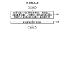
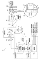
本実施形態では、図1に示すように、ピストン21とシリンダ22との間に介在される流体23の流れを可視化する場合を想定して説明を行うことにする。
ピストン21はシリンダ22内をα方向に往復動する駆動部である。流体23は時間の経過と共に流れており、特にピストン21がシリンダ22内を駆動することによって流体23の状況(例えば、厚さ)は変化する。シリンダ22には開口部22aが形成されており、開口部22aにはガラスなどの透明な材料でできた嵌合部材22bが設置されている。これにより、シリンダ22の外部から開口部22aを介して、流体23を観察することができる。以下では、開口部22aを介して観察できる流体23の範囲を観察部と称する。In the present embodiment, as shown in FIG. 1, the description will be made on the assumption that the flow of the fluid 23 interposed between the
The
流体23には、図示しないフォトクロミック化合物が溶解されている。フォトクロミック化合物は、例えば、スピロピラン系の1,3,3-Trimethylindolino-6'-nitrobenzopyrylospiranである。このスピロピラン系の化合物は、特定波長の光を吸収することで、無色のスピロピランから発色するメロシアニン構造へと変化する。流体23は、フォトクロミック化合物を溶解することができるものであればよく、例えば油である。流体23の粘度は特に限定されず、流体23には粘度が高い物質(例えば、ゲル状の物質)も含まれる。
A photochromic compound (not shown) is dissolved in the
図1に示すように、本実施形態に係る可視化システム1は、位置発信手段2と、変異発生光源3と、ミラー4と、照明光源5と、分離手段6と、一組のCCDカメラ91,92と、流体の流れ可視化装置10(以下では単に「可視化装置10」)とを備えて構成される。なお、ここではCCDカメラとしたが、第1の波長領域および第2の波長領域の光を撮影できるカメラであれば、CMOSや撮像管を使うものなど様々なカメラであってよい。
分離手段6は、イメージスプリッティングダイクロイックミラー(DM)7と、一組のバンドパスフィルタ(BPF)81,82とを備えて構成される。
可視化装置10は、一組のイメージメモリ111,112と、画像処理手段12と、表示部15と、制御部16とを備えて構成される。画像処理手段12は、さらに吸光度演算部13と、2次元パターン化部14とを備えて構成される。なお、可視化装置10は、流体の計測装置の一例である。As shown in FIG. 1,
The separation means 6 includes an image splitting dichroic mirror (DM) 7 and a set of bandpass filters (BPF) 8 1 , 8 2 .
位置発信手段2は、駆動部であるピストン21の位置情報を可視化装置10に発信する。なお、ピストン21を静止させた状態で時間の経過による流体23の潤滑状態を観測する場合、可視化システム1は位置発信手段2を含まない構成でよい。
位置発信手段2は、例えばピストン21に繋がるクランク(図示せず)に取り付けられたエンコーダから回転位置を取得し、予め決められた回転位置で信号を可視化装置10に出力する。また、位置発信手段2は、エンジンへの制御信号に基づいて信号を出力するもの、ピストン21の位置を直接検出して信号を出力するもの、時間経過からピストン21の位置を予測して信号を検出するものなどであってもよい。高速回転している回転軸を支持する軸受の潤滑状態を観測する場合、回転軸の角度信号を可視化装置10に出力する。The position transmitting means 2 transmits the position information of the
The position transmitting means 2 acquires a rotation position from, for example, an encoder attached to a crank (not shown) connected to the
変異発生光源3は、開口部22aを介して流体23に含まれるフォトクロミック化合物にフォトクロミズムを生じさせる変異発生光31を照射する装置である。変異発生光31の波長は、フォトクロミック化合物の種類によって適宜選択されるのがよく、例えば紫外光である。変異発生光源3は、例えば窒素レーザー(波長337nm)やYAGレーザー(波長1064nm)であり、紫外光を発射する場合にはYAGレーザーの第三高調波や第四高調波を使う。ピストン21の往復動による流体23の潤滑状態を観測する場合、変異発生光31をパルス発振するのがよい。変異発生光31をパルス発振するタイミングは、ピストン21の往復動作に対応させるのがよく、変異発生光31は、ピストン21の特定の位置に照射される。流体中の測定する範囲を調整する方法としては、変異発生光源3にレーザーを用いることや、レンズで焦点を絞ることで変異発生光31を照射する範囲を狭めることができる。また、レンズで焦点を広げることで、変異発生光31を照射する範囲を広げることができる。なお、測定範囲の調整は、変異発生光31を照射する範囲を調整できれば、この方法に限定されない。
The mutation generation
流体23に溶解されたフォトクロミック化合物の色素の分子構造は、変異発生光31によって変異し、それに伴って特定の波長領域における光の吸収量が変化する。以下では、変異発生光31を照射されることにより光の吸収量が変化する波長領域を「第1の波長領域」と称し、変異発生光31を照射されても光の吸収量が全くまたは殆ど変化しない波長領域を「第2の波長領域」と称する。第1の波長領域は、例えば緑色の光に対応する波長領域であり、第2の波長領域は、例えば赤色の光に対応する波長領域である。
なお、フォトクロミズムによる色素の分子構造の変異は可逆的であり、熱や光の吸収によって元の分子構造に逆変異する。その為、分子構造が変異した後の流体23を撮影する場合には、変異フォトクロミック化合物に与える熱や光の量を最小限に抑えるのがよい。流体23の撮影についての詳細は後述する。The molecular structure of the dye of the photochromic compound dissolved in the fluid 23 is mutated by the mutation-generating
The mutation of the molecular structure of the dye due to photochromism is reversible, and it reversely mutates to the original molecular structure by absorption of heat and light. Therefore, when photographing the fluid 23 after the molecular structure is mutated, it is preferable to minimize the amount of heat and light given to the mutated photochromic compound. Details of the imaging of the fluid 23 will be described later.
ミラー4は、変異発生光31を反射する装置である。このミラー4は、変異発生光31を特定の照射位置に反射させるように設置されている。
The
照明光源5は、開口部22aを介して撮影に必要な照明光32を流体23に照射する装置である。照明光32は、第1の波長領域の光と第2の波長領域の光とを含む。以下では、照明光32の内で第1の波長領域の光を「第1の照明光」と称し、第2の波長領域の光を「第2の照明光」と称する。照明光源5は、例えば白色LED(Light Emitting Diode)である。
The
照明光源5は、流体23を撮影するタイミングに合わせて照明光32をパルス光として照射する。照明光32を照射する時間は、変異フォトクロミック化合物における分子構造の逆変異を最小限に抑えるために、流体23の撮影を行える範囲の内でできるだけ短い時間(例えば数ミリ秒)であるのがよい。原理的には、CCDカメラ91,92のシャッタが開き、CCD(撮像素子)が露光されている時間(以下では「シャッタ時間」と称する)より短ければよい。CCDカメラ91,92のシャッタ時間以上の露光は、変異フォトクロミック化合物の変異を減衰させるだけなので望ましくない。The
なお、照明光源5の形状は、本発明との関係で特に限定されるものではない。照明光源5は、例えばバー状(棒状)や矩形状のものであってもよい。また、照明光源5は、第1の照明光と第2の照明光とを選択的に発射する別々の装置として構成されていてもよい。
The shape of the
分離手段6は、照明光32が流体23に反射された光(厳密には流体23を透過してピストン21に反射した光)である反射光33を、第1の波長領域と第2の波長領域とに分離する装置である。ここでは、イメージスプリッティングダイクロイックミラー7とバンドパスフィルタ81,82とを備える構成を例示したが、反射光33を第1の波長領域と第2の波長領域とに分離することができれば、分離手段6は他の方法であってもよい。また、ここでの分離手段6は、イメージスプリッティングダイクロイックミラー(DM)7と、一組のバンドパスフィルタ(BPF)81,82とを備える単一の装置として示しているが、イメージスプリッティングダイクロイックミラー7とバンドパスフィルタ81,82とは別々の装置として構成されてもよい。なお、分離手段6は、その処理過程において反射光33により撮像される画像形状を維持する必要がある。The separation means 6 sets the reflected
イメージスプリッティングダイクロイックミラー7は、反射波長帯と透過波長帯とを有しており、反射光33の内で反射波長帯の光341を反射し、反射光33の内で透過波長帯の光342を透過する。例えば、反射波長帯には第1の波長領域が含まれ、一方、透過波長帯には第2の波長領域が含まれる。Image splitting dichroic mirror 7 has a reflection wavelength band and the transmission wavelength band, and reflects light 34 first reflection wavelength band among the reflected
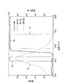
図2を参照して、ここでのイメージスプリッティングダイクロイックミラー7の反射・透過特性について説明する。図2に示す曲線41は、変異フォトクロミック化合物の吸光特性を示すものであり、光の波長[nm]と流体23に溶解されるフォトクロミック化合物の吸光度(着色前の光強度と着色後の光強度との比率の対数)との関係を表している。ここでのフォトクロミック化合物は、変異発生光31を照射することにより、波長が520nm周辺の光の吸収量が最も変化し、波長が長くなる又は短くなるにつれて光の吸収量の変化も小さくなる。そして、波長が700nmを超えたあたりから光の吸収量は殆ど変化しない。
The reflection / transmission characteristics of the image splitting dichroic mirror 7 here will be described with reference to FIG. The
また、図2に示す曲線42は、イメージスプリッティングダイクロイックミラー7の反射・透過特性を示すものであり、光の波長[nm]と透過率[%]との関係を表している(Semrock社,製品コード:FF560-FDi01-25×36)。ここでのイメージスプリッティングダイクロイックミラー7は、波長が570nm未満の光を反射し、波長が570nm以上の光を透過させる。つまり、イメージスプリッティングダイクロイックミラー7の反射波長帯(波長が570nm未満)には、第1の波長領域が含まれており、一方、透過波長帯(波長が570nm以上)には、第2の波長領域が含まれている。したがって、イメージスプリッティングダイクロイックミラー7は、第1の波長領域を含む光341を反射すると共に第2の波長領域を含む光342を透過することにより分離している。Further, the
バンドパスフィルタ81,82は、特定の波長領域の光を通過させる装置である。図2を参照して、ここでのバンドパスフィルタ81,82の透過特性について説明する。図2に示す曲線43は、バンドパスフィルタ81の透過特性を示すものであり、光の波長[nm]と透過率[%]との関係を表している(Semrock社,製品コード:FF01-512/25-25)。ここでのバンドパスフィルタ81は、波長が490〜540nm周辺の光を透過させ、それ以外の領域の波長を透過させない。バンドパスフィルタ81が透過させる波長の領域には、第1の波長領域が含まれる。以下では、バンドパスフィルタ81を通過した光を「第1の反射光351」称する。Bandpass filters 8 1 and 8 2 are devices that allow light in a specific wavelength region to pass through. The transmission characteristics of the bandpass filters 8 1 and 8 2 here will be described with reference to FIG.
また、図2に示す曲線44は、バンドパスフィルタ82の透過特性を示すものであり、光の波長[nm]と透過率[%]との関係を表している(Semrock社,製品コード:FF01-630/92-25)。ここでのバンドパスフィルタ82は、波長が580〜680nm周辺の光を透過させ、それ以外の領域の波長を透過させない。バンドパスフィルタ82が透過させる波長の領域には、第2の波長領域が含まれる。以下では、バンドパスフィルタ82を通過した光を「第2の反射光352」称する。The
CCDカメラ91,92は、流体23の撮影画像を生成する装置である。
CCDカメラ91は、バンドパスフィルタ81を通過した第1の反射光351(例えば、波長が490〜540nm周辺の光)により流体23の第1画像Bを生成する。ここでの第1画像Bには、変異発生光31を照射する前のものと変異発生光31を照射した後のものとが含まれる。以下では、変異発生光31を照射する前のものを「第1画像B10」で表し、変異発生光31を照射した後のものを「第1画像B11」で表す場合がある。
CCDカメラ92は、バンドパスフィルタ82を通過した第2の反射光352(例えば、波長が580〜680nm周辺の光)により流体23の第2画像Cを生成する。ここでの第2画像Cには、変異発生光31を照射する前のものと変異発生光31を照射した後のものとが含まれる。以下では、変異発生光31を照射する前のものを「第2画像C10」で表し、変異発生光31を照射した後のものを「第2画像C11」で表す場合がある。The CCD cameras 9 1 and 9 2 are devices that generate captured images of the fluid 23.
CCD camera 9 1, the first reflected light 35 1 which has passed through the band-pass filter 8 1 (e.g., a wavelength of light near 490~540Nm) to generate a first image B of the fluid 23 by. The first image B here includes an image before irradiation with the
CCD camera 9 2, the second reflected light 35 2 which has passed through the band pass filter 8 2 (e.g., a wavelength of light near 580~680Nm) to generate a second image C of the fluid 23 by. The second image C here includes an image before irradiation with the
可視化装置10は、CCDカメラ91,92によって生成された第1画像B及び第2画像Cから流体23の流れを可視化する装置である。
イメージメモリ(IM)111,112は、CCDカメラ91,92によって生成された撮影画像を記憶する装置である。イメージメモリ111にはCCDカメラ91によって生成された第1画像Bが記憶され、イメージメモリ112にはCCDカメラ92によって生成された第2画像Cが記憶される。イメージメモリ111,112は、「第1画像記憶手段」、「第2画像記憶手段」の一例である。なお、イメージメモリ111,112は、一つの装置であってもよく、その場合には一つのイメージメモリ11に第1画像Bおよび第2画像Cが記憶される。
Image memory (IM) 11 1, 11 2 is a device for storing a photographed image generated by the CCD camera 9 1, 9 2. The image memory 11 1 is stored in the first image B generated by the CCD camera 9 1, second image C to the image memory 11 2 is generated by the CCD camera 9 2 are stored. Image memory 11 1, 11 2, "the first image storage unit", is an example of the "second image storage unit". Incidentally, the image memory 11 1, 11 2 may be a single device, the first image B and the second image C is stored in one image memory 11 in that case.
バンドパスフィルタ81を通過した第1の反射光351は、第1の波長領域の光なので、時間経過と共に撮影された第1画像Bには流体23内の変異フォトクロミック化合物の各時刻における分布が写し出される。ここで、流体23の状況(例えば、油膜厚さ)が変化した場合に、第1画像Bに写し出される変異フォトクロミック化合物の分布には、流体の状況の変化の影響が反映される。一方、バンドパスフィルタ82を通過した第2の反射光352は、第2の波長領域の光なので、時間経過と共に撮影された第2画像Cには各時刻における流体23の状況が写し出される。Since the first reflected
画像処理手段12は、イメージメモリ111,112から第1画像B及び第2画像Cを取得し、取得した第1画像B及び第2画像Cを用いて画像処理を行い、第3画像Dを新たに生成する。画像処理手段12は、吸光度演算部13と、2次元パターン化部14とを備えて構成される。画像処理手段12は、例えばCPU(Central Processing Unit)によるプログラム実行処理や、専用回路等により実現される。The image processing means 12, image memory 11 1, 11 2 from the acquired first image B and the second image C, performs image processing using the first image B and the second image C acquired, the third image D Is newly generated. The image processing means 12 includes an
吸光度演算部13は、変異発生光31を照射する前の流体23を撮影した第1画像B10および第2画像C10と、変異発生光31を照射した後の流体23を撮影した第1画像B11および第2画像C11とを用い、これらの画像の比を取ってから対数を算出し、これらの差分を算出することで吸光度を算出する。
例えば、変異発生光31を照射する前の第1画像B10を構成する画素の光強度を「I10」とし、変異発生光31を照射する前の第2画像C10を構成する画素の光強度を「I20」と定義する。また、変異発生光31を照射した後の第1画像B11を構成する画素の光強度を「I11」とし、変異発生光31を照射した後の第2画像C11を構成する画素の光強度を「I21」と定義する。
この場合に、吸光度演算部13は、次式(2)を用いて各画素における吸光度Aを計算する。なお、LOGは常用対数である。
A=−LOG(I11/I21)−(−LOG(I10/I20))・・・式(2)
=−LOG((I11/I21)/(I10/I20)) ・・・式(2)The
For example, the light of the pixels constituting the second image C 10 before the light intensity of the pixels constituting the first image B 10 before irradiating the mutations generated light 31 is set to "I1 0", irradiates the mutation generated light 31 The intensity is defined as "I 2 0 ". Further, the light intensity of the pixels constituting the first image B 11 after irradiation with the
In this case, the
A = -LOG (I1 1 / I2 1 )-(-LOG (I1 0 / I2 0 )) ... Equation (2)
= -LOG ((I1 1 / I2 1 ) / (I1 0 / I2 0 )) ・ ・ ・ Equation (2)
2次元パターン化部14は、吸光度演算部13により算出された吸光度Aに基づいて第3画像Dを生成する。2次元パターン化部14は、例えば前記式(2)により計算された各画素の吸光度を2次元パターン化することで第3画像Dを生成する。
その為、第3画像Dには、流体の状況の変化の影響を低減した変異フォトクロミック化合物の分布の変化が写し出される。これにより、可視化装置10は、流体の流れをより鮮明に可視化することができる。The two-dimensional patterning unit 14 generates the third image D based on the absorbance A calculated by the
Therefore, the third image D shows a change in the distribution of the mutant photochromic compound, which reduces the influence of the change in the fluid condition. As a result, the
表示部15は、例えばディスプレイであり、2次元パターン化部14により生成された第3画像Dを表示する。
制御部16は、可視化システム1を構成する装置(位置発信手段2、変異発生光源3、照明光源5、CCDカメラ91,92、画像処理手段12など)を制御する。詳細は後記する「流体の流れ可視化システムの動作」で説明する。制御部16は、例えばCPU(Central Processing Unit)、ROM(Read Only Memory)、RAM(Random Access Memory)等により構成される。なお、可視化装置10以外の装置が制御部16を備える構成でもよい。The
The
≪流体の流れ可視化システムの動作≫
次に、本実施形態の可視化システム1の動作について説明する。本実施形態の可視化システム1は、駆動部であるピストン21が静止している状態、及び運動している状態の何れかの状態の流体23を開口部22aを通して撮影し、流体23の流れを可視化することができる。ここで、駆動部であるピストン21が静止している状態の流体23を時間経過と共に撮影することで、時間の経過による流体23の潤滑状態を観測することができる。一方、駆動部であるピストン21が運動している状態の流体23を時間経過と共に撮影することで、ピストン21の往復動による流体23の潤滑状態を観測することができる。なお、可視化システム1の動作は、流体の計測方法の一例である。≪Operation of fluid flow visualization system≫
Next, the operation of the
<駆動部であるピストンが静止している場合の動作>
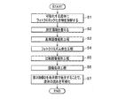
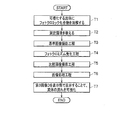
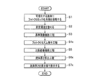
図3ないし図7を参照して(適宜、図1参照)、駆動部であるピストン21が静止している場合の動作について説明する。図3は、流体の流れ可視化システム1の全体動作を示すフローチャートであり、図4ないし図7は、各工程を説明するためのフローチャートである。<Operation when the piston, which is the drive unit, is stationary>
The operation when the
最初に、可視化する流体23にフォトクロミック化合物を溶解し(ステップS1)、また、流体の流れ可視化システム1の測定環境を整える(ステップS2)。これにより、事前の準備が完了する。ステップS1,S2は、特許請求の範囲の「準備工程」である。
First, the photochromic compound is dissolved in the fluid 23 to be visualized (step S1), and the measurement environment of the fluid
次に、基準画像撮影工程を行う(ステップS3)。ここでの基準画像は、フォトクロミック化合物がフォトクロミズムを発生させる前の画像であり、第1画像B10および第2画像C10を少なくとも1枚ずつを撮影する。基準画像としての第1画像B10と第2画像C10とは、同時刻に撮影されたものである。ステップS3は、特許請求の範囲の「変異前画像撮影工程」である。Next, a reference image shooting step is performed (step S3). The reference image here is an image before the photochromic compound causes photochromism, and at least one image B 10 and a second image C 10 are taken. The first image B 10 and the second image C 10 as the reference images were taken at the same time. Step S3 is a “pre-mutation imaging step” within the scope of the claims.
次に、フォトクロミズム発生工程を行う(ステップS4)。フォトクロミズム発生工程は、紫外光などの変異発生光31を流体23に照射することにより、フォトクロミック化合物を変異させる工程である。この工程で、流体の可視化する領域が確定する。ステップS4は、特許請求の範囲の「変異発生光照射工程」である。 Next, a photochromism generation step is performed (step S4). The photochromism generation step is a step of mutating a photochromic compound by irradiating the fluid 23 with mutation generation light 31 such as ultraviolet light. In this step, the area to be visualized of the fluid is determined. Step S4 is a “mutation-generating light irradiation step” within the scope of the claims.
次に、比較画像撮影工程を行う(ステップS5)。比較画像は、フォトクロミック化合物がフォトクロミズムを発生させた後の画像であり、第1画像B11および第2画像C11を少なくとも1枚ずつ撮影する。比較画像としての第1画像B11と第2画像C11とは、同時刻に撮影されたものである。ステップS5は、特許請求の範囲の「変異後画像撮影工程」である。Next, a comparative image shooting step is performed (step S5). The comparative image is an image after the photochromic compound causes photochromism, and at least one first image B 11 and one second image C 11 are taken. The first image B 11 and the second image C 11 as comparative images were taken at the same time. Step S5 is a “post-mutation imaging step” within the scope of the claims.
次に、画像処理工程を行う(ステップS6)。画像処理工程は、基準画像撮影工程で撮影した第1画像B10および第2画像C10と、比較画像撮影工程で撮影した第1画像B11および第2画像C11とを用いて第3画像Dを生成する。第3画像Dには、装置の汚れや傷等による変色の影響の軽減だけではなく、流体の表面の動き、気泡の分布等の流体の状況の変化の影響等の様々なノイズが同時に低減した変異フォトクロミック化合物の分布の変化が写し出される。そして、第3画像Dを表示部15で表示することで、流体23の流れを可視化する(ステップS7)。Next, an image processing step is performed (step S6). In the image processing step, a third image is used by using the first image B 10 and the second image C 10 taken in the reference image taking step and the first image B 11 and the second image C 11 taken in the comparative image taking step. Generate D. In the third image D, not only the influence of discoloration due to dirt and scratches on the device was reduced, but also various noises such as the influence of changes in the fluid condition such as the movement of the fluid surface and the distribution of bubbles were simultaneously reduced. Changes in the distribution of mutant photochromic compounds are projected. Then, the flow of the fluid 23 is visualized by displaying the third image D on the display unit 15 (step S7).
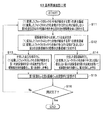
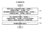
図4を参照して、基準画像撮影工程(ステップS3)について説明する。
まず、照明光源5は、(1)変異したフォトクロミック化合物が吸収する第1の波長領域、および(2)変異したフォトクロミック化合物が全くまたは殆ど吸収しない第2の波長領域の2種類の光を含む照明光32を観察部全体に照射する(ステップS11)。これにより、第1の照明光および第2の照明光は、観察部に同時に照射される。The reference image capturing step (step S3) will be described with reference to FIG.
First, the
次に、分離手段6は、観察部全体から反射してくる反射光33を(1)変異したフォトクロミック化合物が吸収する第1の波長領域、(2)変異したフォトクロミック化合物が全くまたは殆ど吸収しない第2の波長領域の2種類の波長領域に分光する(ステップS12)。 Next, the separation means 6 has a first wavelength region in which the mutated photochromic compound absorbs the reflected light 33 reflected from the entire observation unit, and (2) the mutated photochromic compound absorbs the mutated photochromic compound at all or hardly. Spectroscopy is performed in two types of wavelength regions of two wavelength regions (step S12).
次に、分光した波長領域のうちの(1)変異したフォトクロミック化合物が吸収する第1の波長領域の第1の反射光351を用いて観察部全体を画像化し、基準画像としての第1画像B10を得る(ステップS13)。
また、分光した波長領域のうちの(2)変異したフォトクロミック化合物が全くまたは殆ど吸収しない第2の波長領域の第2の反射光352を用いて観察部全体を画像化し、基準画像としての第2画像C10を得る(ステップS14)。Next, the entire observation unit is imaged using the first reflected light 351 in the first wavelength region absorbed by the (1) mutated photochromic compound in the dispersed wavelength region, and the first image as a reference image. Obtain B 10 (step S13).
In addition, the entire observation section is imaged using the second reflected light 352 in the second wavelength region in which the (2) mutated photochromic compound in the dispersed wavelength region hardly or hardly absorbs, and the first image is used as a reference image. 2 Image C 10 is obtained (step S14).
次に、可視化装置10は、画像化した第1画像B10および第2画像C10を記憶部であるイメージメモリ111,112に記憶する(ステップS15)。そして、測定を完了するか否かを判定する(ステップS16)。測定を完了する場合に本工程を終了する。一方、引き続き第1画像B10および第2画像C10を取得する場合に、ステップS11〜S15の処理を繰り返し行う。これにより、複数の第1画像B10および第2画像C10が得られ、これらを平均したものを基準画像とすることで、流体23をより鮮明に可視化することができる。Next, the
図5を参照して、フォトクロミズム発生工程(ステップS4)について説明する。
本工程では、変異発生光源3が、フォトクロミック化合物の組成を変異させる変異発生光31を観察部領域内の測定したい位置に照射する(ステップS21)。
これにより、流体23の測定したい位置に溶解しているフォトクロミック化合物が特定の波長領域の光を吸収する組成に変異する(ステップS22)。The photochromism generation step (step S4) will be described with reference to FIG.
In this step, the mutation generation
As a result, the photochromic compound dissolved at the position to be measured in the fluid 23 is mutated to a composition that absorbs light in a specific wavelength region (step S22).
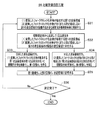
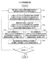
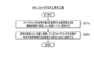
図6を参照して、比較画像撮影工程(ステップS5)について説明する。
まず、照明光源5は、(1)変異したフォトクロミック化合物が吸収する第1の波長領域、および(2)変異したフォトクロミック化合物が全くまたは殆ど吸収しない第2の波長領域の2種類の光を含む照明光32を観察部全体に照射する(ステップS31)。これにより、第1の照明光および第2の照明光は、観察部に同時に照射される。The comparative image capturing step (step S5) will be described with reference to FIG.
First, the
次に、分離手段6は、観察部全体から反射してくる反射光33を(1)変異したフォトクロミック化合物が吸収する第1の波長領域、(2)変異したフォトクロミック化合物が全くまたは殆ど吸収しない第2の波長領域の2種類の波長領域に分光する(ステップS32)。 Next, the separation means 6 has a first wavelength region in which the mutated photochromic compound absorbs the reflected light 33 reflected from the entire observation unit, and (2) the mutated photochromic compound absorbs the mutated photochromic compound at all or hardly. Spectroscopy is performed in two types of wavelength regions of two wavelength regions (step S32).
次に、分光した波長領域のうちの(1)変異したフォトクロミック化合物が吸収する第1の波長領域の第1の反射光351を用いて観察部全体を画像化し、比較画像としての第1画像B11を得る(ステップS33)。
また、分光した波長領域のうちの(2)変異したフォトクロミック化合物が全くまたは殆ど吸収しない第2の波長領域の第2の反射光352を用いて観察部全体を画像化し、比較画像としての第2画像C11を得る(ステップS34)。Next, the entire observation unit is imaged using the first reflected light 351 in the first wavelength region absorbed by the (1) mutated photochromic compound in the dispersed wavelength region, and the first image as a comparative image. Obtain B 11 (step S33).
In addition, the entire observation section is imaged using the second reflected light 352 in the second wavelength region in which the (2) mutated photochromic compound in the dispersed wavelength region hardly or hardly absorbs, and the first is used as a comparative image. 2 Image C 11 is obtained (step S34).
次に、可視化装置10は、画像化した第1画像B11および第2画像C11を記憶部であるイメージメモリ111,112に記憶する(ステップS35)。そして、測定を完了するか否かを判定する(ステップS36)。測定を完了する場合に本工程を終了する。一方、引き続き第1画像B11および第2画像C11を取得する場合に、ステップS31〜S35の処理を時間の経過と共に繰り返し行う。これにより、時系列の第1画像B11および第2画像C11が得られる。Next, the
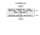
図7を参照して、画像処理工程(ステップS6)について説明する。
本工程では、記憶部に記憶されている基準画像(第1画像B10、第2画像C10)および比較画像(第1画像B11、第2画像C11)の同じ位置にある画素の輝度値を使って、画素毎に吸光度Aを算出して第3画像Dを得る(ステップS41)。そして、生成した第3画像Dを画像処理手段12内の図示しない記憶部に記憶する(ステップS42)。The image processing step (step S6) will be described with reference to FIG. 7.
In this step, the brightness of the pixels at the same position of the reference image (first image B 10 , second image C 10 ) and the comparison image (first image B 11 , second image C 11 ) stored in the storage unit. Using the value, the absorbance A is calculated for each pixel to obtain the third image D (step S41). Then, the generated third image D is stored in a storage unit (not shown) in the image processing means 12 (step S42).
<駆動部であるピストンが往復動している場合の動作>
図8ないし図12を参照して(適宜、図1参照)、駆動部であるピストン21が往復動している場合の動作について説明する。図8は、流体の流れ可視化システム1の全体動作を示すフローチャートであり、図9ないし図12は、各工程を説明するためのフローチャートである。<Operation when the piston, which is the drive unit, reciprocates>
The operation when the
駆動部であるピストン21が往復動している場合の全体動作は、ステップT1〜ステップT7からなり、このうちのステップT1,T2,T7は、駆動部であるピストン21が静止している場合の動作のステップS1,S2,S7(図3参照)と同様である。以下では、処理の異なる基準画像撮影工程(ステップT3)、フォトクロミズム発生工程(ステップT4)、比較画像撮影工程(ステップT5)、および画像処理工程(ステップT6)について説明する。なお、ステップT1,T2は、特許請求の範囲の「準備工程」である。また、ステップT3は、特許請求の範囲の「変異前画像撮影工程」である。また、ステップT4は、特許請求の範囲の「変異発生光照射工程」である。また、ステップT5は、特許請求の範囲の「変異後画像撮影工程」である。
The overall operation when the
図9を参照して、基準画像撮影工程(ステップT3)について説明する。
まず、可視化装置10の制御部16は、事前に設定した「測定する装置の駆動部(ここでは、ピストン21)の動作単位」で照明光源5が光を照射するための信号を送信する(ステップT11)。そして、照明光源5は、信号を受信した場合に、(1)変異したフォトクロミック化合物が吸収する波長領域、および(2)変異したフォトクロミック化合物が全くまたは殆ど吸収しない波長領域の2種類の光を含む照明光32を観察部全体に照射する(ステップT12)。これにより、第1の照明光および第2の照明光は、撮影位置にあるピストン21に同時に照射される。The reference image capturing step (step T3) will be described with reference to FIG.
First, the
次に、分離手段6は、観察部全体から反射してくる反射光33を(1)変異したフォトクロミック化合物が吸収する第1の波長領域、(2)変異したフォトクロミック化合物が全くまたは殆ど吸収しない第2の波長領域の2種類の波長領域に分光する(ステップT13)。 Next, the separation means 6 has a first wavelength region in which the mutated photochromic compound absorbs the reflected light 33 reflected from the entire observation unit, and (2) the mutated photochromic compound absorbs the mutated photochromic compound at all or hardly. Spectroscopy is performed in two types of wavelength regions of two wavelength regions (step T13).
次に、分光した波長領域のうちの(1)変異したフォトクロミック化合物が吸収する第1の波長領域の第1の反射光351を用いて観察部全体を画像化し、基準画像としての第1画像B10を得る(ステップT14)。
また、分光した波長領域のうちの(2)変異したフォトクロミック化合物が全くまたは殆ど吸収しない第2の波長領域の第2の反射光352を用いて観察部全体を画像化し、基準画像としての第2画像C10を得る(ステップT15)。Next, the entire observation unit is imaged using the first reflected light 351 in the first wavelength region absorbed by the (1) mutated photochromic compound in the dispersed wavelength region, and the first image as a reference image. Obtain B 10 (step T14).
In addition, the entire observation section is imaged using the second reflected light 352 in the second wavelength region in which the (2) mutated photochromic compound in the dispersed wavelength region hardly or hardly absorbs, and the first image is used as a reference image. 2 Obtain image C 10 (step T15).
次に、可視化装置10は、「装置の駆動部の位置情報」と、「画像化した第1画像B10および第2画像B20」とを対応付けて記憶部であるイメージメモリ111,112に記憶する(ステップT16)。そして、測定を完了するか否かを判定する(ステップT17)。測定を完了する場合に本工程を終了する。一方、引き続き第1画像B10および第2画像C10を取得する場合に、ステップT11〜T16の処理を繰り返し行う。これにより、駆動部の位置毎の第1画像B10および第2画像C10が得られる。Next, the
図10を参照して、フォトクロミズム発生工程(ステップT4)について説明する。
まず、測定する装置の駆動部(ここでは、ピストン21)の位置情報をモニタリングし(ステップT21)、駆動部の位置が特定位置であるか否かを判定する(ステップT22)。駆動部の位置が特定位置である場合に処理をステップT23に進める。The photochromism generation step (step T4) will be described with reference to FIG.
First, the position information of the drive unit (here, the piston 21) of the device to be measured is monitored (step T21), and it is determined whether or not the position of the drive unit is a specific position (step T22). When the position of the drive unit is a specific position, the process proceeds to step T23.
次に、変異発生光源3が、フォトクロミック化合物の組成を変異させる変異発生光31を観察部領域内の測定したい位置に照射する(ステップT23)。
これにより、流体23の測定したい位置に溶解しているフォトクロミック化合物が特定の波長領域の光を吸収する組成に変異する(ステップT24)。Next, the mutation generation
As a result, the photochromic compound dissolved at the position to be measured in the fluid 23 is mutated to a composition that absorbs light in a specific wavelength region (step T24).
図11を参照して、比較画像撮影工程(ステップT5)について説明する。
まず、可視化装置10の制御部16は、事前に設定した「測定する装置の駆動部(ここでは、ピストン21)の動作単位」で照明光源5が光を照射するための信号を送信する(ステップT31)。そして、照明光源5は、信号を受信した場合に、(1)変異したフォトクロミック化合物が吸収する第1の波長領域、および(2)変異したフォトクロミック化合物が全くまたは殆ど吸収しない第2の波長領域の2種類の光を含む照明光32を観察部全体に照射する(ステップT32)。これにより、第1の照明光および第2の照明光は、撮影位置にあるピストン21に同時に照射される。The comparative image capturing step (step T5) will be described with reference to FIG.
First, the
次に、分離手段6は、観察部全体から反射してくる反射光33を(1)変異したフォトクロミック化合物が吸収する第1の波長領域、(2)変異したフォトクロミック化合物が全くまたは殆ど吸収しない第2の波長領域の2種類の波長領域に分光する(ステップT33)。 Next, the separation means 6 has a first wavelength region in which the mutated photochromic compound absorbs the reflected light 33 reflected from the entire observation unit, and (2) the mutated photochromic compound absorbs the mutated photochromic compound at all or hardly. Spectroscopy is performed in two types of wavelength regions of two wavelength regions (step T33).
次に、分光した波長領域のうちの(1)変異したフォトクロミック化合物が吸収する第1の波長領域の第1の反射光351を用いて観察部全体を画像化し、比較画像としての第1画像B11を得る(ステップT34)。
また、分光した波長領域のうちの(2)変異したフォトクロミック化合物が全くまたは殆ど吸収しない第2の波長領域の第2の反射光352を用いて観察部全体を画像化し、比較画像としての第2画像C11を得る(ステップT35)。Next, the entire observation unit is imaged using the first reflected light 351 in the first wavelength region absorbed by the (1) mutated photochromic compound in the dispersed wavelength region, and the first image as a comparative image. Obtain B 11 (step T34).
In addition, the entire observation section is imaged using the second reflected light 352 in the second wavelength region in which the (2) mutated photochromic compound in the dispersed wavelength region hardly or hardly absorbs, and the first is used as a comparative image. 2 Obtain image C 11 (step T35).
次に、可視化装置10は、「装置の駆動部の運動回数情報および位置情報」と、「画像化した第1画像B11および第2画像C11」とを対応付けて記憶部であるイメージメモリ111,112に記憶する(ステップT36)。なお、運動回数情報と位置情報との組合せは、時刻情報の一例である。そして、測定を完了するか否かを判定する(ステップT37)。測定を完了する場合に本工程を終了する。一方、引き続き第1画像B11および第2画像C11を取得する場合に、ステップT31〜T36の処理を時間の経過と共に繰り返し行う。これにより、時系列の第1画像B11および第2画像C11が得られる。Next, the
図12を参照して、画像処理工程(ステップT6)について説明する。
まず、記憶部に記憶されている基準画像(第1画像B10、第2画像C10)および比較画像(第1画像B11、第2画像C11)のうち、装置の駆動部の位置情報が同じである基準画像(第1画像B10、第2画像C10)および比較画像(第1画像B11、第2画像C11)を抽出する(ステップT41)。
次に、抽出した基準画像(第1画像B10、第2画像C10)および比較画像(第1画像B11、第2画像C11)の同じ位置にある画素の輝度値を使って、画素毎に吸光度Aを算出して第3画像Dを得る(ステップT42)。そして、生成した第3画像Dを画像処理手段12内の図示しない記憶部に記憶する(ステップT43)。The image processing step (step T6) will be described with reference to FIG.
First, among the reference images (first image B 10 , second image C 10 ) and comparison images (first image B 11 , second image C 11 ) stored in the storage unit, the position information of the drive unit of the device. The reference image (first image B 10 , second image C 10 ) and the comparison image (first image B 11 , second image C 11 ) having the same are extracted (step T41).
Next, using the brightness values of the pixels at the same positions of the extracted reference image (first image B 10 , second image C 10 ) and the comparison image (first image B 11 , second image C 11 ), the pixels are used. Absorbance A is calculated for each time to obtain a third image D (step T42). Then, the generated third image D is stored in a storage unit (not shown) in the image processing means 12 (step T43).
以上のように、本実施形態に係る流体の流れ可視化システム1は、光の吸収量が変化する第1の波長領域を用いて流体23の第1画像Bを撮影し、また、光の吸収量が全くまたは殆ど変化しない波長領域を用いて流体23の第2画像Cを撮影する。
第1の波長領域は、変異発生光31によって変異したフォトクロミック化合物の光の吸収量が変化する領域なので、時間経過と共に撮影された第1画像Bには流体内の変異フォトクロミック化合物の各時刻における分布が写し出される。ここで、流体の状況(例えば、油膜厚さ)が変化した場合に、第1画像Bに写し出される変異フォトクロミック化合物の分布には、流体23の状況の変化の影響が反映される。
第2の波長領域は変異発生光31によって変異したフォトクロミック化合物の光の吸収量が全くまたは殆ど変化しない領域なので、時間経過と共に撮影された第2画像Cには各時刻における流体23の状況が写し出される。As described above, the fluid
Since the first wavelength region is a region in which the amount of light absorbed by the photochromic compound mutated by the mutated light 31 changes, the distribution of the mutated photochromic compound in the fluid at each time is shown in the first image B taken with the passage of time. Is projected. Here, when the condition of the fluid (for example, the oil film thickness) changes, the influence of the change in the condition of the fluid 23 is reflected in the distribution of the mutant photochromic compound projected on the first image B.
Since the second wavelength region is a region in which the amount of light absorbed by the photochromic compound mutated by the mutated
そして、可視化システム1は、変異発生光31を照射する前の流体23を撮影した第1画像B10および第2画像C10と、変異発生光31を照射した後の流体を撮影した第1画像B11および第2画像C11とを用い、これらの画像の比を取ってから対数を算出し、これらの差分を算出することで第3画像Dを生成する。
ここで、第1の波長領域の光、第2の波長領域の光によって反射率が異なる部分がある場合(例えば、エッジ部)や、2つの光源を使う等によって第1の波長領域の光と第2の波長領域の光の強度分布が異なる場合(例えば、第1画像上部が明るく、第2画像下部が明るい等の場合)であっても、変異発生光を照射する前の第1画像B10と変異発生光を照射した後の第1画像B11および変異発生光を照射する前の第2画像C10と変異発生光を照射した後の第2画像C11には、ほぼ同じ状態の第1の波長領域の光および第2の波長領域の光によって流体の状況が写し出される。
その為、第3画像Dには、装置の汚れや傷等による変色の影響の軽減だけではなく、第1の波長領域の光、第2の波長領域の光の波長の違いによって反射率が異なる部分や、第1の波長領域の光と第2の波長領域の光の強度分布が異なることによって生ずる光による様々なノイズが同時に低減され、着色された変異フォトクロミック化合物の分布の変化がより鮮明に写し出される。これにより、本実施形態に係る流体の流れ可視化システム1は、動く物体中や変化する場のような流体の状況が変化し易い測定環境でも、流体23の流れをより鮮明に可視化することができる。Then, the
Here, when there is a portion where the reflectance differs depending on the light in the first wavelength region and the light in the second wavelength region (for example, the edge portion), or when two light sources are used, the light in the first wavelength region and the light in the first wavelength region are used. Even if the light intensity distribution in the second wavelength region is different (for example, the upper part of the first image is bright, the lower part of the second image is bright, etc.), the first image B before irradiating the mutation-generating light. The first image B 11 after irradiating 10 and the mutation-generating light, the second image C 10 before irradiating the mutation-generating light, and the second image C 11 after irradiating the mutation-generating light are in almost the same state. The light in the first wavelength region and the light in the second wavelength region project the state of the fluid.
Therefore, in the third image D, not only the influence of discoloration due to dirt or scratches on the device is reduced, but also the reflectance differs depending on the difference in wavelength between the light in the first wavelength region and the light in the second wavelength region. Various noises due to light caused by different intensity distributions of light in the first wavelength region and light in the second wavelength region are simultaneously reduced, and changes in the distribution of colored mutant photochromic compounds become clearer. It is projected. As a result, the fluid
なお、従来技術では、白色光を用いて流体の撮影を行っていた。ここで、白色光で撮影した画像には、流体内の変異フォトクロミック化合物の各時刻における分布と、流体の状況の変化の影響とが反映されている。その為、白色光で撮影した画像から演算した吸光度は、変異フォトクロミック化合物の分布の変化のみならず流体の状況の変化の影響を受けることになる。したがって、従来技術では、動く物体中や変化する場のような流体の状況が変化し易い測定環境において、流れを鮮明に可視化することが難しかった。 In the prior art, the fluid was photographed using white light. Here, the image taken with white light reflects the distribution of the mutant photochromic compound in the fluid at each time and the influence of the change in the state of the fluid. Therefore, the absorbance calculated from the image taken with white light is affected not only by the change in the distribution of the mutant photochromic compound but also by the change in the fluid condition. Therefore, with the prior art, it has been difficult to clearly visualize the flow in a measurement environment where the fluid condition is likely to change, such as in a moving object or in a changing field.
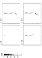
本実施形態に係る可視化システム1により生成した第3画像Dの具体例を図13に示す。図13に示す第3画像Dは、図1に示すピストン21を静止している状態で、流体23を時間経過と共に撮影した画像から生成したものである。
ここでは、フォトクロミック化合物として、スピロピラン系の1,3,3-Trimethylindolino-6'-nitrobenzopyrylospiran(東京化成工業株式会社,製品コード:T0366)を使用し、流体23としてエステルオイルを使用した。
また、フォトクロミック化合物にフォトクロミズムを生じさせる変異発生光31として紫外光を使用し、変異発生光源3としては窒素レーザー(波長337nm)又はYAGレーザー(波長1064nmの第三高調波355nm)を使用した。FIG. 13 shows a specific example of the third image D generated by the
Here, a spiropirane-based 1,3,3-Trimethylindolino-6'-nitrobenzopyrylospiran (Tokyo Chemical Industry Co., Ltd., product code: T0366) was used as the photochromic compound, and ester oil was used as the
Further, ultraviolet light was used as the
図13(a)は変異発生光31を照射した直後(0秒)の第3画像Dを示し、(b)は10秒後の第3画像Dを示し、(c)は20秒後の第3画像Dを示し、(d)は30秒後の第3画像Dを示す。図13では、吸光度を濃淡で表しており、色が濃いほど吸光度が高くなっている。
第3画像Dには流体の状況の変化の影響を低減した変異フォトクロミック化合物の分布の変化が写し出されるので、図13に示すように、変異発生光31を照射された部分(吸光度が高い部分)が時間経過と共に図面下側に移動しているのが鮮明に分かる。FIG. 13A shows a third image D immediately after irradiation with the mutation generating light 31 (0 seconds), FIG. 13B shows a
Since the change in the distribution of the mutant photochromic compound with reduced influence of the change in the fluid condition is projected on the third image D, as shown in FIG. 13, the portion irradiated with the mutation generation light 31 (the portion having high absorbance). Can be clearly seen moving to the bottom of the drawing over time.
[第2実施形態]
≪流体の流体厚さ測定システムの構成≫
流体の流体厚さ測定システム(以下では単に「厚さ測定システム」)は、測定対象である流体の厚さを測定するシステムであり、例えばピストン、シリンダ、すべり軸受などのすべり面である動く物体中で使用される潤滑剤の厚さ(油膜厚さ)を測定する。なお、厚さ測定システムは、流体の計測システムの一例である。[Second Embodiment]
<< Configuration of fluid thickness measurement system for fluid >>
A fluid thickness measurement system for fluids (hereinafter simply referred to as a "thickness measurement system") is a system that measures the thickness of the fluid to be measured, and is a moving object that is a sliding surface such as a piston, cylinder, or sliding bearing. Measure the thickness (oil film thickness) of the lubricant used inside. The thickness measurement system is an example of a fluid measurement system.
図14に示すように、本実施形態に係る厚さ測定システム1xは、位置発信手段2と、変異発生光源3と、ミラー4と、照明光源5と、分離手段6と、一組のCCDカメラ91,92と、流体の流体厚さ測定装置10x(以下では単に「厚さ測定装置10x」)とを備えて構成される。ここで、第1実施形態に係る可視化システム1(図1参照)と同様の構成要素については同一の符号を付して説明を省略し、以下では主に機能の異なる構成要素について説明する。なお、流体23には、第1実施形態と同様に、図示しないフォトクロミック化合物が溶解されている。As shown in FIG. 14, the
厚さ測定装置10xは、一組のイメージメモリ111,112と、流体厚さ算出手段12xと、表示部15と、制御部16とを備えて構成される。流体厚さ算出手段12xは、さらに吸光度演算部13と、流体厚さ演算部14xとを備えて構成される。なお、厚さ測定装置10xは、流体の計測装置の一例である。
CCDカメラ91,92は、流体23の撮影画像を生成する装置である。
CCDカメラ91は、バンドパスフィルタ81を通過した第1の反射光351(例えば、波長が490〜540nm周辺の光)により流体23の第1画像Bを生成する。ここでの第1画像Bには、変異発生光31を照射する前のものと変異発生光31を照射した後のものとが含まれる。以下では、第1実施形態と同様に、変異発生光31を照射する前のものを「第1画像B10」で表し、変異発生光31を照射した後のものを「第1画像B11」で表す場合がある。
CCDカメラ92は、バンドパスフィルタ82を通過した第2の反射光352(例えば、波長が580〜680nm周辺の光)により流体23の第2画像Cを生成する。ここでの第2画像Cには、変異発生光31を照射する前のものと変異発生光31を照射した後のものとが含まれる。以下では、第1実施形態と同様に、変異発生光31を照射する前のものを「第2画像C10」で表し、変異発生光31を照射した後のものを「第2画像C11」で表す場合がある。The CCD cameras 9 1 and 9 2 are devices that generate captured images of the fluid 23.
CCD camera 9 1, the first reflected light 35 1 which has passed through the band-pass filter 8 1 (e.g., a wavelength of light near 490~540Nm) to generate a first image B of the fluid 23 by. The first image B here includes an image before irradiation with the
CCD camera 9 2, the second reflected light 35 2 which has passed through the band pass filter 8 2 (e.g., a wavelength of light near 580~680Nm) to generate a second image C of the fluid 23 by. The second image C here includes an image before irradiation with the
厚さ測定装置10xは、CCDカメラ91,92によって生成された第1画像B及び第2画像Cから流体23の厚さを測定する装置である。
イメージメモリ(IM)111,112は、CCDカメラ91,92によって生成された撮影画像を記憶する装置である。イメージメモリ111にはCCDカメラ91によって生成された第1画像Bが記憶され、イメージメモリ112にはCCDカメラ92によって生成された第2画像Cが記憶される。イメージメモリ111,112は、「第1画像記憶手段」、「第2画像記憶手段」の一例である。なお、イメージメモリ111,112は、一つの装置であってもよく、その場合には一つのイメージメモリ11に第1画像Bおよび第2画像Cが記憶される。
Image memory (IM) 11 1, 11 2 is a device for storing a photographed image generated by the CCD camera 9 1, 9 2. The image memory 11 1 is stored in the first image B generated by the CCD camera 9 1, second image C to the image memory 11 2 is generated by the CCD camera 9 2 are stored. Image memory 11 1, 11 2, "the first image storage unit", is an example of the "second image storage unit". Incidentally, the image memory 11 1, 11 2 may be a single device, the first image B and the second image C is stored in one image memory 11 in that case.
バンドパスフィルタ81を通過した第1の反射光351は、第1の波長領域の光なので、特定の時刻に撮影された第1画像Bには流体23内の変異フォトクロミック化合物の特定の時刻における分布が写し出される。ここで、流体23の状況(例えば、油膜厚さ)が変化した場合に、第1画像Bに写し出される変異フォトクロミック化合物の分布には、流体の状況の変化の影響が反映される。一方、バンドパスフィルタ82を通過した第2の反射光352は、第2の波長領域の光なので、特定の時刻に撮影された第2画像Cには特定の時刻における流体23の状況が写し出される。Since the first reflected
流体厚さ算出手段12xは、イメージメモリ111,112から第1画像B及び第2画像Cを取得し、取得した第1画像B及び第2画像Cを用いて流体23の厚さl(ここでは、油膜厚さ)を算出する。流体厚さ算出手段12xは、吸光度演算部13と、流体厚さ演算部14xとを備えて構成される。流体厚さ算出手段12xは、例えばCPU(Central Processing Unit)によるプログラム実行処理や、専用回路等により実現される。Fluid thickness calculating means 12x, the image memory 11 1, 11 2 from the acquired first image B and the second image C, the obtained thickness of the first image B and the second image using C fluid 23 l ( Here, the oil film thickness) is calculated. The fluid thickness calculation means 12x includes an
吸光度演算部13の機能は、第1実施形態と同様である。つまり、吸光度演算部13は、変異発生光31を照射する前の流体23を撮影した第1画像B10および第2画像C10と、変異発生光31を照射した後の流体23を撮影した第1画像B11および第2画像C11とを用い、これらの画像の比を取ってから対数を算出し、これらの差分を算出することで吸光度を算出する。
例えば、変異発生光31を照射する前の第1画像B10を構成する画素の光強度を「I10」とし、変異発生光31を照射する前の第2画像C10を構成する画素の光強度を「I20」と定義する。また、変異発生光31を照射した後の第1画像B11を構成する画素の光強度を「I11」とし、変異発生光31を照射した後の第2画像C11を構成する画素の光強度を「I21」と定義する。
この場合に、吸光度演算部13は、次式(2)を用いて各画素における吸光度Aを計算する。なお、LOGは常用対数である。
A=−LOG(I11/I21)−(−LOG(I10/I20))・・・式(2)
=−LOG((I11/I21)/(I10/I20)) ・・・式(2)The function of the
For example, the light of the pixels constituting the second image C 10 before the light intensity of the pixels constituting the first image B 10 before irradiating the mutations generated light 31 is set to "I1 0", irradiates the mutation generated light 31 The intensity is defined as "I 2 0 ". Further, the light intensity of the pixels constituting the first image B 11 after irradiation with the
In this case, the
A = -LOG (I1 1 / I2 1 )-(-LOG (I1 0 / I2 0 )) ... Equation (2)
= -LOG ((I1 1 / I2 1 ) / (I1 0 / I2 0 )) ・ ・ ・ Equation (2)
流体厚さ演算部14xは、吸光度演算部13により算出された吸光度Aに基づいて流体23の厚さlを算出する。例えば、フォトクロミック化合物を溶解した後の流体23の吸光係数を「μ」と定義する。
この場合に、流体厚さ演算部14xは、次式(4)を用いて測定対象部分の画素における流体23の厚さlを計算する。
l=A/μ ・・・式(4)The fluid thickness calculation unit 14x calculates the thickness l of the fluid 23 based on the absorbance A calculated by the
In this case, the fluid thickness calculation unit 14x calculates the thickness l of the fluid 23 in the pixel of the measurement target portion using the following equation (4).
l = A / μ ・ ・ ・ Equation (4)
表示部15は、流体厚さ演算部14xにより計算された流体23の厚さlを表示する。なお、表示部15は、第1実施形態と同様に、第3画像Dを併せて表示してもよい。つまり、流体厚さ算出手段12xは、第1実施形態で説明した2次元パターン化部14の機能を備え、表示部15は、2次元パターン化部14により生成された第3画像Dを流体23の厚さlとともに表示してもよい。また、嵌合部材22bから確認できる流体23全体に変異発生光31を照射した場合は、第3画像Dを構成している吸光度Aを、式(4)を用いて流体23の厚さlに変換することで、流体23の厚さlの分布として表示してもよい。
The
前記式(4)についてさらに詳しく説明する。
本発明の発明者は、実験を行うことにより吸光度が流体厚さに比例し、吸光度と流体厚さとの関係を前記式(4)で表すことができることを確認した。実験の様子を図15に示す。流体厚さと吸光度との関係を調べるためには、既知の厚さの流体を用意する必要がある。そこで、図15に示すように、金属球61と平板状のガラス62とを接触させ、その間を流体である試験溶液63で満たすことで既知の厚さを作り出した。つまり、試験溶液63の厚さは、金属球61と平板状のガラス62との距離mであるので、金属球61の直径が分かれば、金属球61と平板状のガラス62との接触点61aからの距離からそれぞれの場所における流体厚さを計算できる。実験で使用した金属球61の直径は「100mm」である。試験溶液63としてはエステルオイルを使用し、試験溶液63にはスピロピラン系のフォトクロミック化合物が溶解されている。試験溶液63の質量パーセント濃度は、「0.4mass%」とした。なお、金属球61は、移動しないように設置台64に固定されている。The equation (4) will be described in more detail.
The inventor of the present invention confirmed by conducting an experiment that the absorbance is proportional to the fluid thickness and that the relationship between the absorbance and the fluid thickness can be expressed by the above formula (4). The state of the experiment is shown in FIG. In order to investigate the relationship between the fluid thickness and the absorbance, it is necessary to prepare a fluid of a known thickness. Therefore, as shown in FIG. 15, the
次に、窒素レーザーに波長が近い紫外光LEDランプ(図示せず)を用いて、符号65で示す方向から試験溶液63に光を十分に照射する。実験で使用した紫外光LEDランプが発する光の波長は、「340nm」である。これにより、試験溶液63に溶解されるフォトクロミック化合物の色素の分子構造は変異し、試験溶液63は全体が着色される。ここで、試験溶液63は、完全に着色している必要があり、変異していない箇所が部分的に残っている場合には、流体厚さと吸光度との関係を調べることができない。そして、図14で示したのと同様に、分離手段6を用いて符号65で示す方向から撮影を行い、前記した式(2)を用いて各画素における吸光度Aを計算する。実験結果を図16に示す。図16に示すように、流体厚さ(ここでは、「油膜厚さ」と表示)に対して吸光度が線形に高くなっているのが分かる。この実験では、フォトクロミック化合物を溶解させた試験溶液63の吸光係数μが線形近似線より「0.03」程度であることが確認された。なお、吸光係数μは、試験溶液63およびフォトクロミック化合物の種類や質量パーセント濃度などにより決まる。当該実験で求めた吸光係数μを用いて算出した試験溶液63の厚さの分布を図17に示す。図17における中心は、金属球61と平板状のガラス62との接触点61a(図15参照)である。図17に示すように、接触点61aから離れるにつれて試験溶液63の厚さが大きくなるのが明確に分かる。
Next, the
≪流体の流体厚さ測定システムの動作≫
次に、図18を参照して(適宜、図14参照)、本実施形態の厚さ測定システム1xの動作について説明する。ここでは、駆動部であるピストン21が静止している状態の流体23を開口部22aを通して撮影し、流体23の厚さを測定する場合を説明する。なお、ここで説明する厚さ測定システム1xの動作は、流体の計測方法の一例である。≪Operation of fluid thickness measurement system for fluid≫
Next, the operation of the
図18は、厚さ測定システム1xの全体動作を示すフローチャートである。図18に示すように、厚さ測定システム1xの全体動作は、ステップS1〜ステップS7xからなり、このうちのステップS1,S2,S3,S5は、第1実施形態におけるピストン21が静止している場合の動作(図3参照)と同様である。以下では、処理の異なる工程(ステップS4x,S6x,S7x)について主に説明する。なお、ステップS1,S2は、特許請求の範囲の「準備工程」である。また、ステップS3は、特許請求の範囲の「変異前画像撮影工程」である。また、ステップS4xは、特許請求の範囲の「変異発生光照射工程」である。また、ステップS5は、特許請求の範囲の「変異後画像撮影工程」である。
FIG. 18 is a flowchart showing the overall operation of the
図19を参照して、フォトクロミズム発生工程(ステップS4x)について説明する。
本工程では、変異発生光源3が、フォトクロミック化合物の組成を変異させる変異発生光31を観察部領域内の測定したい位置に十分に照射する(ステップS21x)。変異発生光31を十分に照射とは、流体23の表面のみならず厚さ方向に対して深くまで変異発生光31が届くことを意味する。
これにより、流体23の測定したい位置に溶解しているフォトクロミック化合物が特定の波長領域の光を吸収する組成に完全に変異する(ステップS22x)。フォトクロミック化合物が完全に変異とは、流体23の厚さ方向において変異していない箇所が部分的に残っていないことを意味する。The photochromism generation step (step S4x) will be described with reference to FIG.
In this step, the mutation-generating
As a result, the photochromic compound dissolved at the position to be measured in the fluid 23 is completely mutated to a composition that absorbs light in a specific wavelength region (step S22x). When the photochromic compound is completely mutated, it means that there are no partially mutated portions in the thickness direction of the fluid 23.
図20を参照して、流体厚さ算出工程(ステップS6x)について説明する。
本工程では、記憶部に記憶されている基準画像(第1画像B10、第2画像C10)および比較画像(第1画像B11、第2画像C11)の同じ位置にある画素の輝度値を使って吸光度Aを算出する(ステップS41x)。
また、本工程では、予め確認しておいた流体23の吸光係数μと算出した吸光度Aとを用いて流体23の厚さlを算出する(ステップS42x)。そして、計算した流体23の厚さlを表示部15に表示する(図18のステップS7x)。The fluid thickness calculation step (step S6x) will be described with reference to FIG.
In this step, the brightness of the pixels at the same positions of the reference image (first image B 10 , second image C 10 ) and the comparison image (first image B 11 , second image C 11 ) stored in the storage unit. The absorbance A is calculated using the values (step S41x).
Further, in this step, the thickness l of the fluid 23 is calculated by using the absorption coefficient μ of the fluid 23 confirmed in advance and the calculated absorbance A (step S42x). Then, the calculated thickness l of the fluid 23 is displayed on the display unit 15 (step S7x in FIG. 18).
以上説明した第2実施形態に係る厚さ測定システム1xによっても、第2実施形態と略同等の効果を奏することができる。つまり、第1画像Bおよび第2画像Cを用いて算出した流体厚さlは、様々なノイズの影響が低減されることにより正確な値となる。
The
以上、本発明の実施形態について説明したが、本発明はこれに限定されるものではなく、特許請求の範囲の趣旨を変えない範囲で実施することができる。 Although the embodiments of the present invention have been described above, the present invention is not limited to this, and can be carried out within a range that does not change the gist of the claims.
第1実施形態では、画像処理手段12は、イメージメモリ111,112から第1画像B及び第2画像Cを取得し、取得した第1画像B及び第2画像Cを用いて画像処理を行い、第3画像Dを新たに生成していた。具体的には、画像処理手段12は、変異発生光31を照射する前の流体23を撮影した第1画像B10および第2画像C10と、変異発生光31を照射した後の流体23を撮影した第1画像B11および第2画像C11とを用い、これらの画像の比を取ってから対数を算出し、これらの差分を算出することで吸光度を算出し、計算された各画素の吸光度を2次元パターン化していた。
しかしながら、画像処理手段12は、イメージメモリ111から変異発生光31を照射した後の流体23を撮影した第1画像B11を取得し、第1画像B11を表示部15に表示するようにしてもよい。この第1画像B11には、流体23内の変異フォトクロミック化合物の各時刻における分布が鮮明に写し出されるので、本実施形態の第3画像Dには及ばないまでも、動く物体中、変化する場のような測定環境でも測定対象物を鮮明に可視化することができる。In the first embodiment, the image processing unit 12, an image memory 11 1, 11 2 from the acquired first image B and the second image C, the image processing using the first image B and the second image C obtained This was performed, and the third image D was newly generated. Specifically, the image processing means 12 captures the first image B 10 and the second image C 10 in which the fluid 23 before the
However, the image processing unit 12 obtains the first image B 11 obtained by photographing the fluid 23 after irradiation with mutations generated light 31 from the image memory 11 1, so as to display the first image B 11 on the
また、画像処理手段12は、イメージメモリ111から変異発生光31を照射した後の流体23を撮影した第1画像B11を取得し、また、イメージメモリ112から変異発生光31を照射した後の流体23を撮影した第2画像C11を取得し、これらの画像から第3画像Dを生成してもよい。
この場合、画像処理手段12は、次式(1)を用いて各画素における吸光度A1を計算し、各画素の計算結果を2次元パターン化することで第3画像Dを生成する。ここで、「I11」は、変異発生光31を照射した後の第1画像B11を構成する画素の光強度である。また、「I21」は、変異発生光31を照射した後の第2画像C11を構成する画素の光強度である。また、LOGは常用対数である。
A1=−LOG(I11/I21)・・・式(1)
同時刻の第1画像B11および第2画像C11には、同じ状態の流体表面の動き、気泡の分布等の流体の状況が写し出されるので、第1画像B11および第2画像C11を用いた第3画像Dでは、流体の表面の動き、気泡の分布等の流体の状況の変化の影響等の様々なノイズが低減され、着色された変異フォトクロミック化合物の分布の変化がより鮮明に写し出される。
なお、第1の波長領域の光、第2の波長領域の光の波長の違いによって反射率が異なる部分があったり、第1の波長領域の光と第2の波長領域の光の強度分布が異なる部分があったりする場合に、これらの光の影響が様々なノイズとして反映されることになる。そのため、第1の波長領域の光と第2の波長領域の光の影響によって様々なノイズが発生する場合には、本実施形態で示した通り、変異発生光31を照射する前の流体23を撮影した第1画像B10および第2画像C10と、変異発生光31を照射した後の流体23を撮影した第1画像B11および第2画像C11とを用いて第3画像Dを生成するのが望ましい。Further, the image processing unit 12 obtains the first image B 11 obtained by photographing the fluid 23 after irradiation with mutations generated light 31 from the image memory 11 1, it was also irradiated with mutations generated light 31 from the image memory 11 2 The second image C 11 obtained by photographing the
In this case, the image processing means 12 calculates the absorbance A1 in each pixel using the following equation (1), and generates the third image D by two-dimensionally patterning the calculation result of each pixel. Here, "I 1 1 " is the light intensity of the pixels constituting the first image B 11 after the
A1 = -LOG (I1 1 / I2 1 ) ... Equation (1)
Since the fluid conditions such as the movement of the fluid surface and the distribution of bubbles in the same state are projected on the first image B 11 and the second image C 11 at the same time, the first image B 11 and the second image C 11 are displayed. In the third image D used, various noises such as the movement of the surface of the fluid and the influence of changes in the fluid condition such as the distribution of bubbles are reduced, and the change in the distribution of the colored mutant photochromic compound is more clearly projected. Is done.
In addition, there is a part where the reflectance differs depending on the difference in wavelength between the light in the first wavelength region and the light in the second wavelength region, and the intensity distribution of the light in the first wavelength region and the light in the second wavelength region is different. When there are different parts, the influence of these lights will be reflected as various noises. Therefore, when various noises are generated due to the influence of the light in the first wavelength region and the light in the second wavelength region, as shown in this embodiment, the fluid 23 before irradiating the
なお、第2実施形態における流体厚さ算出手段12xについても同様であり、前記した式(1)を用いて第1画像B11及び第2画像C11から吸光度A1を計算し、また、次式(3)を用いて流体23の厚さlを計算してもよい。ここで、「μ」は、フォトクロミック化合物を溶解した後の流体23の吸光係数である。
l=A1/μ ・・・式(3)The same applies to the fluid thickness calculating means 12x in the second embodiment, and the absorbance A1 is calculated from the first image B 11 and the second image C 11 using the above formula (1), and the following formula is also used. The thickness l of the fluid 23 may be calculated using (3). Here, "μ" is the extinction coefficient of the fluid 23 after the photochromic compound is dissolved.
l = A1 / μ ・ ・ ・ Equation (3)
また、第1実施形態では、開口部22aを介して観察できる流体23は、駆動部を円滑に駆動させるための潤滑油であるため、液体膜(薄い膜)であるが、流体23の表面を可視化するのであれば、流体23は厚い液体であってもよい。つまり、観察対象である流体23の厚さは特に限定されない。
また、第1実施形態では、分離手段6は、照明光32が流体23に反射された光(厳密には流体23を透過してピストン21に反射した光)である反射光33を、第1の波長領域と第2の波長領域とに分離するが、観察部が光を透過する構造の場合(例えば、ガラスとガラスの間に流体23がある構造)は、分離手段6は、照明光32が観察部を透過してきた光である透過光を第1の波長領域と第2の波長領域に分離してもよい。つまり、分離手段6は、流体23を透過した透過光を分離するものであればよい。
また、本実施形態では、駆動部としてピストン21を想定していたが、駆動部は往復動または回転するものであればよい。つまり、駆動部は、時刻と駆動部の位置とが対応づけられるものであればよい。Further, in the first embodiment, the fluid 23 that can be observed through the
Further, in the first embodiment, the separating means 6 first receives the reflected
Further, in the present embodiment, the
1 可視化システム(計測システム)
1x 厚さ測定システム(計測システム)
2 位置発信手段
3 変異発生光源
4 ミラー
5 照明光源(照明手段)
6 分離手段
7 イメージスプリッティングダイクロイックミラー
81,82 バンドパスフィルタ
91,92 CCDカメラ(第1撮像手段、第2撮像手段)
10 可視化装置(計測装置)
10x 厚さ測定装置(計測装置)
111,112 イメージメモリ(第1画像記憶手段、第2画像記憶手段)
12 画像処理手段
12x 流体厚さ算出手段
13 吸光度演算部
14 2次元パターン化部
14x 流体厚さ演算部
15 表示部
16 制御部
21 ピストン(駆動部)
22 シリンダ
23 流体1 Visualization system (measurement system)
1x thickness measurement system (measurement system)
2 Position transmission means 3 Mutation generation
6 Separation means 7 Image splitting dichroic mirror 8 1 , 8 2 Bandpass filter 9 1 , 9 2 CCD camera (first imaging means, second imaging means)
10 Visualization device (measuring device)
10x thickness measuring device (measuring device)
11 1 , 11 2 Image memory (first image storage means, second image storage means)
12 Image processing means 12x Fluid thickness calculation means 13 Absorbance calculation unit 14 Two-dimensional patterning unit 14x Fluid
22
Claims (17)
変異発生光を照射することで光の吸収量が変化するフォトクロミック化合物を前記流体に溶解する準備工程と、
フォトクロミズムを生じさせる変異発生光を前記流体に照射する変異発生光照射工程と、
前記変異発生光を照射した後の前記流体の画像を撮影する変異後画像撮影工程と、
前記変異後画像撮影工程の後で行う画像処理工程と、を有し、
前記変異後画像撮影工程では、変異発生光が照射されることによって光の吸収量が変化する第1の波長領域の第1の光を用いて前記流体を撮影することで第1画像を生成し、また、前記吸収量が全くまたは殆ど変化しない第2の波長領域の第2の光を用いて、前記第1画像の撮影と同時刻の前記流体を撮影した第2画像を生成し、
前記画像処理工程では、前記第1画像および前記第2画像を用いて第3画像を生成する、ことを特徴とする計測方法。 It is a fluid measurement method
A preparatory step for dissolving a photochromic compound in which the amount of light absorbed changes by irradiating with mutation-generating light in the fluid, and
A mutation-generating light irradiation step of irradiating the fluid with mutation-generating light that causes photochromism, and
A post-mutation imaging step of photographing the fluid image after irradiation with the mutation-generating light, and
It has an image processing step performed after the post-mutation imaging step .
In the post-mutation imaging step, a first image is generated by photographing the fluid using the first light in the first wavelength region in which the amount of light absorbed changes when the mutation-generating light is irradiated. Further, using the second light in the second wavelength region in which the absorption amount does not change at all or hardly changes, a second image in which the fluid is photographed at the same time as the first image is photographed is generated.
The measurement method, characterized in that, in the image processing step, a third image is generated using the first image and the second image .
前記変異後画像撮影工程で撮影した第2画像を構成する画素の光強度を「I21」とした場合に、
前記画像処理工程では、次式(1)を用いて各画素における吸光度A1を計算し、各画素の計算結果を2次元パターン化することで前記第3画像を生成する
A1=−LOG(I11/I21)・・・式(1)
ことを特徴とする請求項1に記載の計測方法。 The light intensity of the pixels constituting the first image taken in the post-mutation image taking step is set to "I 1 1 ".
When the light intensity of the pixels constituting the second image taken in the post-mutation image taking step is set to "I 2 1 ",
In the image processing step, the absorbance A1 in each pixel is calculated using the following equation (1), and the calculation result of each pixel is two-dimensionally patterned to generate the third image. A1 = -LOG (I1 1) / I2 1 ) ・ ・ ・ Equation (1)
The measurement method according to claim 1 , wherein the measurement method is characterized by the above.
前記変異前画像撮影工程で撮影した第1画像を構成する画素の光強度を「I10」とし、
前記変異前画像撮影工程で撮影した第2画像を構成する画素の光強度を「I20」とした場合に、
前記画像処理工程では、次式(2)を用いて各画素における吸光度Aを計算し、各画素の計算結果を2次元パターン化することで前記第3画像を生成する
A=−LOG(I11/I21)−(−LOG(I10/I20))・・・式(2)
ことを特徴とする請求項2に記載の計測方法。 It has a pre-mutation imaging step of capturing a first image and a second image of the fluid before irradiating the mutation-generating light before the mutation-generating light irradiation step.
The light intensity of the pixels constituting the first image captured by the mutant pre-imaging step to "I1 0",
When the light intensity of the pixels constituting the second image taken in the pre-mutation image taking step is "I2 0 ",
In the image processing step, the absorbance A in each pixel is calculated using the following equation (2), and the calculation result of each pixel is two-dimensionally patterned to generate the third image. A = -LOG (I1 1 1). / I2 1 )-(-LOG (I1 0 / I2 0 )) ... Equation (2)
The measurement method according to claim 2 , wherein the method is characterized by the above.
変異発生光を照射することで光の吸収量が変化するフォトクロミック化合物を前記流体に溶解する準備工程と、
フォトクロミズムを生じさせる変異発生光を前記流体に照射する変異発生光照射工程と、
前記変異発生光を照射した後の前記流体の画像を撮影する変異後画像撮影工程と、
前記変異後画像撮影工程の後で行う流体厚さ算出工程と、を有し、
前記変異後画像撮影工程では、変異発生光が照射されることによって光の吸収量が変化する第1の波長領域の第1の光を用いて前記流体を撮影することで第1画像を生成し、また、前記吸収量が全くまたは殆ど変化しない第2の波長領域の第2の光を用いて、前記第1画像の撮影と同時刻の前記流体を撮影した第2画像を生成し、
前記流体厚さ算出工程では、前記第1画像および前記第2画像を用いて前記流体の厚さを算出する、ことを特徴とする計測方法。 It is a fluid measurement method
A preparatory step for dissolving a photochromic compound in which the amount of light absorbed changes by irradiating with mutation-generating light in the fluid, and
A mutation-generating light irradiation step of irradiating the fluid with mutation-generating light that causes photochromism, and
A post-mutation imaging step of photographing the fluid image after irradiation with the mutation-generating light, and
It has a fluid thickness calculation step performed after the post-mutation imaging step .
In the post-mutation imaging step, a first image is generated by photographing the fluid using the first light in the first wavelength region in which the amount of light absorbed changes when the mutation-generating light is irradiated. Further, using the second light in the second wavelength region in which the absorption amount does not change at all or hardly changes, a second image in which the fluid is photographed at the same time as the first image is photographed is generated.
The measurement method, characterized in that, in the fluid thickness calculation step, the thickness of the fluid is calculated using the first image and the second image .
前記変異後画像撮影工程で撮影した第2画像を構成する画素の光強度を「I21」とし、
前記フォトクロミック化合物を溶解した後の前記流体の吸光係数を「μ」とした場合に、
前記流体厚さ算出工程では、
次式(1)を用いて変異発生光が照射された領域の画素における吸光度A1を計算し、
A1=−LOG(I11/I21)・・・式(1)
さらに、次式(3)を用いて流体厚さlを計算する、
l=A1/μ ・・・式(3)
ことを特徴とする請求項4に記載の計測方法。 The light intensity of the pixels constituting the first image taken in the post-mutation image taking step is set to "I 1 1 ".
The light intensity of the pixels constituting the second image taken in the post-mutation image taking step is set to "I 2 1 ".
When the extinction coefficient of the fluid after dissolving the photochromic compound is set to "μ",
In the fluid thickness calculation step,
Using the following equation (1), the absorbance A1 in the pixel in the region irradiated with the mutagenesis light was calculated.
A1 = -LOG (I1 1 / I2 1 ) ... Equation (1)
Further, the fluid thickness l is calculated using the following equation (3).
l = A1 / μ ・ ・ ・ Equation (3)
The measurement method according to claim 4 , wherein the method is characterized by the above.
前記変異前画像撮影工程で撮影した第1画像を構成する画素の光強度を「I10」とし、
前記変異前画像撮影工程で撮影した第2画像を構成する画素の光強度を「I20」とした場合に、
前記流体厚さ算出工程では、
次式(2)を用いて変異発生光が照射された領域の画素における吸光度Aを計算し、
A=−LOG(I11/I21)−(−LOG(I10/I20))・・・式(2)
さらに、次式(4)を用いて流体厚さlを計算する、
l=A/μ ・・・式(4)
ことを特徴とする請求項5に記載の計測方法。 It has a pre-mutation imaging step of capturing a first image and a second image of the fluid before irradiating the mutation-generating light before the mutation-generating light irradiation step.
The light intensity of the pixels constituting the first image captured by the mutant pre-imaging step to "I1 0",
When the light intensity of the pixels constituting the second image taken in the pre-mutation image taking step is "I2 0 ",
In the fluid thickness calculation step,
Using the following equation (2), the absorbance A in the pixel in the region irradiated with the mutagenesis light was calculated.
A = -LOG (I1 1 / I2 1 )-(-LOG (I1 0 / I2 0 )) ... Equation (2)
Further, the fluid thickness l is calculated using the following equation (4).
l = A / μ ・ ・ ・ Equation (4)
The measurement method according to claim 5 , wherein the method is characterized by the above.
前記吸収量が変化する第1の波長領域の第1の光を用いて前記流体を撮影した第1画像を記憶する第1画像記憶手段と、
前記吸収量が全くまたは殆ど変化しない第2の波長領域の第2の光を用いて、前記第1画像の撮影と同時刻の前記流体を撮影した第2画像を記憶する第2画像記憶手段と、
前記第1画像および前記第2画像を用いて前記流体の流れを可視化した第3画像を生成する画像処理手段と、を備え、
前記画像処理手段は、前記変異発生光を照射した後の前記流体を撮影した前記第1画像および前記第2画像を用いて第3画像を生成する、
ことを特徴とする計測装置。 A measuring device that visualizes the flow of a fluid in which a photochromic compound in which the amount of light absorbed in a specific wavelength region changes when irradiated with mutation-generating light that causes photochromism.
A first image storage means for storing a first image obtained by photographing the fluid using the first light in the first wavelength region in which the absorption amount changes.
With a second image storage means for storing a second image in which the fluid is photographed at the same time as the acquisition of the first image by using the second light in the second wavelength region in which the absorption amount does not change at all or hardly changes. ,
An image processing means for generating a third image in which the flow of the fluid is visualized using the first image and the second image is provided.
The image processing means generates a third image using the first image and the second image obtained by photographing the fluid after irradiating the mutation generating light.
A measuring device characterized by this.
前記変異発生光を照射した後の第2画像を構成する画素の光強度を「I21」とした場合に、
前記画像処理手段は、次式(1)を用いて各画素における吸光度A1を計算し、各画素の計算結果を2次元パターン化することで前記第3画像を生成する
A1=−LOG(I11/I21)・・・式(1)
ことを特徴とする請求項7に記載の計測装置。 The light intensity of the pixels constituting the first image after irradiation with the mutation-generating light is set to "I 1 1 ".
When the light intensity of the pixels constituting the second image after irradiating the mutation-generating light is "I 2 1 ",
The image processing means calculates the absorbance A1 in each pixel using the following equation (1), and generates the third image by two-dimensionally patterning the calculation result of each pixel. A1 = -LOG (I1 1) / I2 1 ) ・ ・ ・ Equation (1)
The measuring device according to claim 7 .
前記変異発生光を照射する前の第2画像を構成する画素の光強度を「I20」とした場合に、
前記画像処理手段は、次式(2)を用いて各画素における吸光度Aを計算し、各画素の計算結果を2次元パターン化することで前記第3画像を生成する
A=−LOG(I11/I21)−(−LOG(I10/I20))・・・式(2)
ことを特徴とする請求項8に記載の計測装置。 The light intensity of the pixels constituting the first image before irradiating the mutations generated light to "I1 0",
When the light intensity of the pixels constituting the second image before irradiating the mutation-generating light is "I2 0 ",
The image processing means calculates the absorbance A in each pixel using the following equation (2), and generates the third image by two-dimensionally patterning the calculation result of each pixel. A = -LOG (I1 1 1). / I2 1 )-(-LOG (I1 0 / I2 0 )) ... Equation (2)
8. The measuring device according to claim 8 .
前記吸収量が変化する第1の波長領域の第1の光を用いて前記流体を撮影した第1画像を記憶する第1画像記憶手段と、
前記吸収量が全くまたは殆ど変化しない第2の波長領域の第2の光を用いて、前記第1画像の撮影と同時刻の前記流体を撮影した第2画像を記憶する第2画像記憶手段と、
前記第1画像および前記第2画像を用いて前記流体の厚さを算出する流体厚さ算出手段と、を備え、
前記流体厚さ算出手段は、前記変異発生光を照射した後の前記流体を撮影した前記第1画像および前記第2画像を用いて前記流体の厚さを算出する、
ことを特徴とする計測装置。 A measuring device that measures the thickness of a fluid in which a photochromic compound whose amount of light absorbed in a specific wavelength region changes when irradiated with mutation-generating light that causes photochromism.
A first image storage means for storing a first image obtained by photographing the fluid using the first light in the first wavelength region in which the absorption amount changes.
With a second image storage means for storing a second image in which the fluid is photographed at the same time as the acquisition of the first image by using the second light in the second wavelength region in which the absorption amount does not change at all or hardly changes. ,
A fluid thickness calculating means for calculating the thickness of the fluid using the first image and the second image is provided.
The fluid thickness calculating means calculates the thickness of the fluid by using the first image and the second image of the fluid after irradiating the mutation generating light.
A measuring device characterized by this.
前記変異発生光を照射した後の第2画像を構成する画素の光強度を「I21」とし、
前記フォトクロミック化合物を溶解した後の前記流体の吸光係数を「μ」とした場合に、
前記流体厚さ算出手段は、
次式(1)を用いて変異発生光が照射された領域の画素における吸光度A1を計算し、
A1=−LOG(I11/I21)・・・式(1)
さらに、次式(3)を用いて流体厚さlを計算する、
l=A1/μ ・・・式(3)
ことを特徴とする請求項10に記載の計測装置。 The light intensity of the pixels constituting the first image after irradiation with the mutation-generating light is set to "I 1 1 ".
The light intensity of the pixels constituting the second image after irradiating the mutation-generating light is set to "I 2 1 ".
When the extinction coefficient of the fluid after dissolving the photochromic compound is set to "μ",
The fluid thickness calculation means is
Using the following equation (1), the absorbance A1 in the pixel in the region irradiated with the mutagenesis light was calculated.
A1 = -LOG (I1 1 / I2 1 ) ... Equation (1)
Further, the fluid thickness l is calculated using the following equation (3).
l = A1 / μ ・ ・ ・ Equation (3)
The measuring device according to claim 10 .
前記変異発生光を照射する前の第2画像を構成する画素の光強度を「I20」とした場合に、
前記流体厚さ算出手段は、
次式(2)を用いて変異発生光が照射された領域の画素における吸光度Aを計算し、
A=−LOG(I11/I21)−(−LOG(I10/I20))・・・式(2)
さらに、次式(4)を用いて流体厚さlを計算する、
l=A/μ ・・・式(4)
ことを特徴とする請求項11に記載の計測装置。 The light intensity of the pixels constituting the first image before irradiating the mutations generated light to "I1 0",
When the light intensity of the pixels constituting the second image before irradiating the mutation-generating light is "I2 0 ",
The fluid thickness calculation means is
Using the following equation (2), the absorbance A in the pixel in the region irradiated with the mutagenesis light was calculated.
A = -LOG (I1 1 / I2 1 )-(-LOG (I1 0 / I2 0 )) ... Equation (2)
Further, the fluid thickness l is calculated using the following equation (4).
l = A / μ ・ ・ ・ Equation (4)
11. The measuring device according to claim 11 .
前記第1の光および前記第2の光を含む照明光を前記流体に照射する照明手段と、
前記流体を透過した後の前記照明光を前記第1の波長領域の第1の光と前記第2の波長領域の第2の光とに分離する分離手段と、
前記分離手段により分離された前記第1の光を撮像し、前記第1画像を生成する第1撮像手段と、
前記分離手段により分離された前記第2の光を撮像し、前記第2画像を生成する第2撮像手段と、を備え、
前記照明手段は、前記第1撮像手段および前記第2撮像手段が撮影を行うタイミングに前記照明光を照射するタイミングを合わせたパルス光として前記照明光を照射する、
ことを特徴とする計測システム。 A measuring apparatus according to any one of claims 7 to 9,
An illumination means for irradiating the fluid with illumination light including the first light and the second light.
A separation means for separating the illumination light after passing through the fluid into a first light in the first wavelength region and a second light in the second wavelength region.
A first imaging means that captures the first light separated by the separation means and generates the first image.
A second imaging means that captures the second light separated by the separating means and generates the second image is provided.
The illumination means irradiates the illumination light as pulsed light in which the timing of irradiating the illumination light is matched with the timing at which the first imaging means and the second imaging means perform photographing.
A measurement system characterized by this.
前記変異発生光源は、前記流体の流れを可視化する領域を決定するために光のサイズを任意の大きさに調整する機能と、前記変異発生光を前記流体の任意の位置に照射する機能とを備え、
前記任意の大きさの前記変異発生光を前記流体の流れを可視化する前記任意の位置にパルス光として前記流体に照射する、ことを特徴とする請求項13に記載の計測システム。 A mutation generation light source for irradiating the mutation generation light is provided.
The mutation-generating light source has a function of adjusting the size of light to an arbitrary size in order to determine a region for visualizing the flow of the fluid, and a function of irradiating the mutation-generating light at an arbitrary position of the fluid. Prepare,
The measurement system according to claim 13 , wherein the mutagenesis light of an arbitrary magnitude is irradiated to the fluid as pulsed light at an arbitrary position for visualizing the flow of the fluid.
前記制御部は、前記駆動部が特定の位置にあるときに前記変異発生光をパルス光として照射するとともに、前記駆動部が特定の撮影位置にあるときに撮影する、ことを特徴とする請求項14に記載の計測システム。 Further provided is a control unit that receives position information of the drive unit when the reciprocating or rotating drive unit is in the fluid and controls the timing at which the lighting means or the mutation generating light source irradiates the fluid. ,
The claim is characterized in that the control unit irradiates the mutation-generated light as pulsed light when the drive unit is at a specific position, and also shoots when the drive unit is at a specific imaging position. 14. The measurement system according to 14 .
前記第1の光および前記第2の光を含む照明光を前記流体に照射する照明手段と、
前記流体を透過した後の前記照明光を前記第1の波長領域の第1の光と前記第2の波長領域の第2の光とに分離する分離手段と、
前記分離手段により分離された前記第1の光を撮像し、前記第1画像を生成する第1撮像手段と、
前記分離手段により分離された前記第2の光を撮像し、前記第2画像を生成する第2撮像手段と、
前記変異発生光を照射する変異発生光源と、を備え、
前記変異発生光源は、前記流体の厚さ方向に対して、フォトクロミック化合物を完全に変異させる、
ことを特徴とする計測システム。 The measuring device according to any one of claims 10 to 12 ,
An illumination means for irradiating the fluid with illumination light including the first light and the second light.
A separation means for separating the illumination light after passing through the fluid into a first light in the first wavelength region and a second light in the second wavelength region.
A first imaging means that captures the first light separated by the separation means and generates the first image.
A second imaging means that captures the second light separated by the separating means and generates the second image,
A mutation generation light source that irradiates the mutation generation light is provided.
The mutagenesis light source completely mutates the photochromic compound with respect to the thickness direction of the fluid.
A measurement system characterized by this.
Applications Claiming Priority (3)
| Application Number | Priority Date | Filing Date | Title |
|---|---|---|---|
| JP2017127827 | 2017-06-29 | ||
| JP2017127827 | 2017-06-29 | ||
| PCT/JP2018/019417 WO2019003715A1 (en) | 2017-06-29 | 2018-05-18 | Fluid measurement method, fluid measurement device, and measurement system |
Publications (2)
| Publication Number | Publication Date |
|---|---|
| JPWO2019003715A1 JPWO2019003715A1 (en) | 2020-04-30 |
| JP6830692B2 true JP6830692B2 (en) | 2021-02-17 |
Family
ID=64741360
Family Applications (1)
| Application Number | Title | Priority Date | Filing Date |
|---|---|---|---|
| JP2019526683A Active JP6830692B2 (en) | 2017-06-29 | 2018-05-18 | Fluid measurement methods, measuring devices and measuring systems |
Country Status (5)
| Country | Link |
|---|---|
| US (1) | US11293876B2 (en) |
| EP (1) | EP3647775B1 (en) |
| JP (1) | JP6830692B2 (en) |
| CN (1) | CN110799831B (en) |
| WO (1) | WO2019003715A1 (en) |
Family Cites Families (13)
| Publication number | Priority date | Publication date | Assignee | Title |
|---|---|---|---|---|
| JPH083492B2 (en) * | 1987-12-02 | 1996-01-17 | 日産自動車株式会社 | Flow image analyzer |
| US5034613A (en) * | 1989-11-14 | 1991-07-23 | Cornell Research Foundation, Inc. | Two-photon laser microscopy |
| FR2723218A1 (en) * | 1994-07-29 | 1996-02-02 | Essilor Internal Cie Gle Optique | PHOTOCHROMIC COMPOUNDS WITH A SPIRO STRUCTURE (INDOLINE- (2,3 ') - BENZOXAZINE) WITH A CYANO GROUP IN 6', AND THEIR USE IN THE FIELD OF OPHTHALMIC OPTICS |
| US5975696A (en) * | 1997-05-12 | 1999-11-02 | Kohan; George | Process for rendering plastic substrate photochromic |
| JP4244536B2 (en) * | 2001-06-13 | 2009-03-25 | 株式会社リコー | In-casing airflow measuring device and airflow optimization processing method in image forming apparatus |
| JP3979568B2 (en) * | 2001-12-10 | 2007-09-19 | 株式会社リコー | Multicolor image display method and apparatus |
| JP2004069396A (en) * | 2002-08-02 | 2004-03-04 | Kri Inc | Fluid detector |
| GB0220985D0 (en) * | 2002-09-10 | 2002-10-23 | Wrc Plc | Combined sewer overflow monitor |
| JP2004170369A (en) | 2002-11-22 | 2004-06-17 | Canon Inc | Method of visualizing flow of polishing liquid, and polishing device |
| JP2006258553A (en) * | 2005-03-16 | 2006-09-28 | Ricoh Co Ltd | Flow evaluation method, flow evaluation device, and flow evaluation program of medium having flow behavior |
| JP5646957B2 (en) * | 2010-11-08 | 2014-12-24 | 三井造船株式会社 | Fluid flow visualization device and visualization method |
| US8617436B2 (en) | 2011-05-18 | 2013-12-31 | Bloomfield Science Museum Jerusalem | Remote marking |
| WO2018094518A1 (en) * | 2016-11-22 | 2018-05-31 | British Columbia Cancer Agency Branch | Dual mode biophotonic imaging systems and their applications for detection of epithelial dysplasia in vivo |
-
2018
- 2018-05-18 WO PCT/JP2018/019417 patent/WO2019003715A1/en unknown
- 2018-05-18 US US16/627,011 patent/US11293876B2/en active Active
- 2018-05-18 CN CN201880043262.2A patent/CN110799831B/en active Active
- 2018-05-18 JP JP2019526683A patent/JP6830692B2/en active Active
- 2018-05-18 EP EP18822823.3A patent/EP3647775B1/en active Active
Also Published As
| Publication number | Publication date |
|---|---|
| CN110799831B (en) | 2022-05-31 |
| WO2019003715A1 (en) | 2019-01-03 |
| CN110799831A (en) | 2020-02-14 |
| EP3647775A1 (en) | 2020-05-06 |
| US20200225167A1 (en) | 2020-07-16 |
| US11293876B2 (en) | 2022-04-05 |
| JPWO2019003715A1 (en) | 2020-04-30 |
| EP3647775B1 (en) | 2023-03-01 |
| EP3647775A4 (en) | 2021-04-07 |
Similar Documents
| Publication | Publication Date | Title |
|---|---|---|
| CN103513411B (en) | The apparatus and method focused in fluorescent microscope | |
| US8809809B1 (en) | Apparatus and method for focusing in fluorescence microscope | |
| US20200092468A1 (en) | Multi-range imaging system and method | |
| JP7116163B2 (en) | Flash optimization during continuous retinal imaging | |
| DE102010009476A1 (en) | Method and device for visualizing spatially resolved measurement results of properties that are not directly visible to the human eye | |
| CA2969643A1 (en) | Online inspection for composite structures | |
| WO2004051186A1 (en) | Method and device for optical form measurement and/or estimation | |
| US20130286396A1 (en) | Inspection device | |
| CN104048813B (en) | The recording method of a kind of damage from laser optical element process and device thereof | |
| JP6830692B2 (en) | Fluid measurement methods, measuring devices and measuring systems | |
| US11759097B2 (en) | Light source device and image-capturing device | |
| JP2021096112A (en) | Inspection device for transparent body | |
| JP2009047469A (en) | Method and device for inspecting color filter using diffracted image | |
| RU2449291C2 (en) | Apparatus and method for three-dimensional measurement of flow rate | |
| JP6587959B2 (en) | Skin image generation device, method of operating skin image generation device, and skin image generation processing program | |
| JP2016065782A (en) | Inspection device | |
| JP2018159671A (en) | Measuring device and program | |
| JP2017111092A (en) | Optical element and optical device, inspection device for the same, and inspection method for the same | |
| HU231357B1 (en) | Method and apparatus for analysing fluorescence of a sample | |
| CN110333248A (en) | The differentiating method of glass surface defects and surface dust fall | |
| JP2020051813A (en) | Measurement method and measurement device | |
| JP6406008B2 (en) | Optical observation device | |
| Hahlweg et al. | Imaging of short time microscopic scenes with strong light emission: revisited | |
| JP2003307484A (en) | Particle feature photographing/measuring apparatus | |
| TWM491159U (en) | Dynamic Raman scatter optical analysis device |
Legal Events
| Date | Code | Title | Description |
|---|---|---|---|
| A621 | Written request for application examination |
Free format text: JAPANESE INTERMEDIATE CODE: A621 Effective date: 20200413 |
|
| A131 | Notification of reasons for refusal |
Free format text: JAPANESE INTERMEDIATE CODE: A131 Effective date: 20201013 |
|
| A521 | Request for written amendment filed |
Free format text: JAPANESE INTERMEDIATE CODE: A523 Effective date: 20201204 |
|
| TRDD | Decision of grant or rejection written | ||
| A01 | Written decision to grant a patent or to grant a registration (utility model) |
Free format text: JAPANESE INTERMEDIATE CODE: A01 Effective date: 20210105 |
|
| A61 | First payment of annual fees (during grant procedure) |
Free format text: JAPANESE INTERMEDIATE CODE: A61 Effective date: 20210113 |
|
| R150 | Certificate of patent or registration of utility model |
Ref document number: 6830692 Country of ref document: JP Free format text: JAPANESE INTERMEDIATE CODE: R150 |
|
| S531 | Written request for registration of change of domicile |
Free format text: JAPANESE INTERMEDIATE CODE: R313531 |
|
| R350 | Written notification of registration of transfer |
Free format text: JAPANESE INTERMEDIATE CODE: R350 |
|
| R250 | Receipt of annual fees |
Free format text: JAPANESE INTERMEDIATE CODE: R250 |