JP6830562B1 - Manufacturing method of Mg-containing particles - Google Patents
Manufacturing method of Mg-containing particles Download PDFInfo
- Publication number
- JP6830562B1 JP6830562B1 JP2020177735A JP2020177735A JP6830562B1 JP 6830562 B1 JP6830562 B1 JP 6830562B1 JP 2020177735 A JP2020177735 A JP 2020177735A JP 2020177735 A JP2020177735 A JP 2020177735A JP 6830562 B1 JP6830562 B1 JP 6830562B1
- Authority
- JP
- Japan
- Prior art keywords
- containing particles
- unclassified
- particles
- classification
- flow velocity
- Prior art date
- Legal status (The legal status is an assumption and is not a legal conclusion. Google has not performed a legal analysis and makes no representation as to the accuracy of the status listed.)
- Active
Links
- 239000002245 particle Substances 0.000 title claims abstract description 624
- 238000004519 manufacturing process Methods 0.000 title claims abstract description 98
- 238000009826 distribution Methods 0.000 claims abstract description 49
- 238000011144 upstream manufacturing Methods 0.000 claims abstract description 39
- 238000005299 abrasion Methods 0.000 claims abstract description 15
- 238000007664 blowing Methods 0.000 claims description 12
- 238000005259 measurement Methods 0.000 claims description 12
- 239000000843 powder Substances 0.000 abstract description 80
- 238000010586 diagram Methods 0.000 abstract 1
- 239000011777 magnesium Substances 0.000 description 362
- 239000011949 solid catalyst Substances 0.000 description 134
- -1 titanium halogen compound Chemical class 0.000 description 92
- 238000006116 polymerization reaction Methods 0.000 description 77
- 150000001336 alkenes Chemical class 0.000 description 73
- 150000001875 compounds Chemical class 0.000 description 72
- 239000000047 product Substances 0.000 description 58
- JRZJOMJEPLMPRA-UHFFFAOYSA-N olefin Natural products CCCCCCCC=C JRZJOMJEPLMPRA-UHFFFAOYSA-N 0.000 description 46
- YXFVVABEGXRONW-UHFFFAOYSA-N Toluene Chemical compound CC1=CC=CC=C1 YXFVVABEGXRONW-UHFFFAOYSA-N 0.000 description 39
- 125000004432 carbon atom Chemical group C* 0.000 description 35
- 239000006185 dispersion Substances 0.000 description 33
- 238000000034 method Methods 0.000 description 31
- 150000002681 magnesium compounds Chemical class 0.000 description 26
- 229920000642 polymer Polymers 0.000 description 25
- 229920000098 polyolefin Polymers 0.000 description 24
- 239000010936 titanium Substances 0.000 description 24
- 238000006243 chemical reaction Methods 0.000 description 23
- 229910052719 titanium Inorganic materials 0.000 description 23
- QQONPFPTGQHPMA-UHFFFAOYSA-N propylene Natural products CC=C QQONPFPTGQHPMA-UHFFFAOYSA-N 0.000 description 22
- 125000004805 propylene group Chemical group [H]C([H])([H])C([H])([*:1])C([H])([H])[*:2] 0.000 description 20
- OFOBLEOULBTSOW-UHFFFAOYSA-N Propanedioic acid Natural products OC(=O)CC(O)=O OFOBLEOULBTSOW-UHFFFAOYSA-N 0.000 description 19
- 239000002685 polymerization catalyst Substances 0.000 description 18
- 239000002253 acid Substances 0.000 description 17
- RTAQQCXQSZGOHL-UHFFFAOYSA-N Titanium Chemical compound [Ti] RTAQQCXQSZGOHL-UHFFFAOYSA-N 0.000 description 15
- 150000002148 esters Chemical class 0.000 description 15
- IMNFDUFMRHMDMM-UHFFFAOYSA-N N-Heptane Chemical compound CCCCCCC IMNFDUFMRHMDMM-UHFFFAOYSA-N 0.000 description 14
- 125000005843 halogen group Chemical group 0.000 description 14
- IUVCFHHAEHNCFT-INIZCTEOSA-N 2-[(1s)-1-[4-amino-3-(3-fluoro-4-propan-2-yloxyphenyl)pyrazolo[3,4-d]pyrimidin-1-yl]ethyl]-6-fluoro-3-(3-fluorophenyl)chromen-4-one Chemical compound C1=C(F)C(OC(C)C)=CC=C1C(C1=C(N)N=CN=C11)=NN1[C@@H](C)C1=C(C=2C=C(F)C=CC=2)C(=O)C2=CC(F)=CC=C2O1 IUVCFHHAEHNCFT-INIZCTEOSA-N 0.000 description 13
- IJGRMHOSHXDMSA-UHFFFAOYSA-N Atomic nitrogen Chemical compound N#N IJGRMHOSHXDMSA-UHFFFAOYSA-N 0.000 description 13
- 239000003054 catalyst Substances 0.000 description 13
- 125000000217 alkyl group Chemical group 0.000 description 12
- 239000007788 liquid Substances 0.000 description 12
- 229920001296 polysiloxane Polymers 0.000 description 11
- 238000002360 preparation method Methods 0.000 description 11
- 230000000052 comparative effect Effects 0.000 description 10
- FYYHWMGAXLPEAU-UHFFFAOYSA-N Magnesium Chemical compound [Mg] FYYHWMGAXLPEAU-UHFFFAOYSA-N 0.000 description 9
- 229910052749 magnesium Inorganic materials 0.000 description 9
- 125000000962 organic group Chemical group 0.000 description 9
- 230000002093 peripheral effect Effects 0.000 description 9
- WKBOTKDWSSQWDR-UHFFFAOYSA-N Bromine atom Chemical group [Br] WKBOTKDWSSQWDR-UHFFFAOYSA-N 0.000 description 8
- VGGSQFUCUMXWEO-UHFFFAOYSA-N Ethene Chemical compound C=C VGGSQFUCUMXWEO-UHFFFAOYSA-N 0.000 description 8
- 239000005977 Ethylene Substances 0.000 description 8
- TWRXJAOTZQYOKJ-UHFFFAOYSA-L Magnesium chloride Chemical compound [Mg+2].[Cl-].[Cl-] TWRXJAOTZQYOKJ-UHFFFAOYSA-L 0.000 description 8
- 239000007795 chemical reaction product Substances 0.000 description 8
- 239000012530 fluid Substances 0.000 description 8
- XDKQUSKHRIUJEO-UHFFFAOYSA-N magnesium;ethanolate Chemical compound [Mg+2].CC[O-].CC[O-] XDKQUSKHRIUJEO-UHFFFAOYSA-N 0.000 description 8
- 239000000243 solution Substances 0.000 description 8
- XJDNKRIXUMDJCW-UHFFFAOYSA-J titanium tetrachloride Chemical compound Cl[Ti](Cl)(Cl)Cl XJDNKRIXUMDJCW-UHFFFAOYSA-J 0.000 description 8
- VZCYOOQTPOCHFL-UHFFFAOYSA-N trans-butenedioic acid Natural products OC(=O)C=CC(O)=O VZCYOOQTPOCHFL-UHFFFAOYSA-N 0.000 description 8
- 239000004711 α-olefin Substances 0.000 description 8
- 125000001931 aliphatic group Chemical group 0.000 description 7
- 229910052736 halogen Inorganic materials 0.000 description 7
- 150000002367 halogens Chemical class 0.000 description 7
- 239000011976 maleic acid Substances 0.000 description 7
- 239000000203 mixture Substances 0.000 description 7
- 229910052757 nitrogen Inorganic materials 0.000 description 7
- 150000002899 organoaluminium compounds Chemical class 0.000 description 7
- 239000011164 primary particle Substances 0.000 description 7
- 239000002904 solvent Substances 0.000 description 7
- 239000000725 suspension Substances 0.000 description 7
- VXNZUUAINFGPBY-UHFFFAOYSA-N 1-Butene Chemical compound CCC=C VXNZUUAINFGPBY-UHFFFAOYSA-N 0.000 description 6
- LFQSCWFLJHTTHZ-UHFFFAOYSA-N Ethanol Chemical compound CCO LFQSCWFLJHTTHZ-UHFFFAOYSA-N 0.000 description 6
- 238000004458 analytical method Methods 0.000 description 6
- 229910052801 chlorine Inorganic materials 0.000 description 6
- 125000001309 chloro group Chemical group Cl* 0.000 description 6
- 125000001495 ethyl group Chemical group [H]C([H])([H])C([H])([H])* 0.000 description 6
- 239000010419 fine particle Substances 0.000 description 6
- 125000001153 fluoro group Chemical group F* 0.000 description 6
- 150000002430 hydrocarbons Chemical group 0.000 description 6
- 125000002496 methyl group Chemical group [H]C([H])([H])* 0.000 description 6
- 239000002994 raw material Substances 0.000 description 6
- XLYOFNOQVPJJNP-UHFFFAOYSA-N water Substances O XLYOFNOQVPJJNP-UHFFFAOYSA-N 0.000 description 6
- BHPDSAAGSUWVMP-UHFFFAOYSA-N 3,3-bis(methoxymethyl)-2,6-dimethylheptane Chemical compound COCC(C(C)C)(COC)CCC(C)C BHPDSAAGSUWVMP-UHFFFAOYSA-N 0.000 description 5
- ZCYVEMRRCGMTRW-UHFFFAOYSA-N 7553-56-2 Chemical group [I] ZCYVEMRRCGMTRW-UHFFFAOYSA-N 0.000 description 5
- UFHFLCQGNIYNRP-UHFFFAOYSA-N Hydrogen Chemical compound [H][H] UFHFLCQGNIYNRP-UHFFFAOYSA-N 0.000 description 5
- 230000009471 action Effects 0.000 description 5
- 238000012661 block copolymerization Methods 0.000 description 5
- 238000007334 copolymerization reaction Methods 0.000 description 5
- 230000006378 damage Effects 0.000 description 5
- 230000007423 decrease Effects 0.000 description 5
- 229910001873 dinitrogen Inorganic materials 0.000 description 5
- 230000000694 effects Effects 0.000 description 5
- 229910052731 fluorine Inorganic materials 0.000 description 5
- 239000007789 gas Substances 0.000 description 5
- 239000011261 inert gas Substances 0.000 description 5
- 229910052740 iodine Inorganic materials 0.000 description 5
- 125000000959 isobutyl group Chemical group [H]C([H])([H])C([H])(C([H])([H])[H])C([H])([H])* 0.000 description 5
- 239000011259 mixed solution Substances 0.000 description 5
- 239000000178 monomer Substances 0.000 description 5
- 125000004108 n-butyl group Chemical group [H]C([H])([H])C([H])([H])C([H])([H])C([H])([H])* 0.000 description 5
- 230000037048 polymerization activity Effects 0.000 description 5
- 230000008569 process Effects 0.000 description 5
- 238000003756 stirring Methods 0.000 description 5
- XKRFYHLGVUSROY-UHFFFAOYSA-N Argon Chemical compound [Ar] XKRFYHLGVUSROY-UHFFFAOYSA-N 0.000 description 4
- KCXVZYZYPLLWCC-UHFFFAOYSA-N EDTA Chemical compound OC(=O)CN(CC(O)=O)CCN(CC(O)=O)CC(O)=O KCXVZYZYPLLWCC-UHFFFAOYSA-N 0.000 description 4
- FHUODBDRWMIBQP-UHFFFAOYSA-N Ethyl p-anisate Chemical compound CCOC(=O)C1=CC=C(OC)C=C1 FHUODBDRWMIBQP-UHFFFAOYSA-N 0.000 description 4
- VEXZGXHMUGYJMC-UHFFFAOYSA-N Hydrochloric acid Chemical compound Cl VEXZGXHMUGYJMC-UHFFFAOYSA-N 0.000 description 4
- KDYFGRWQOYBRFD-UHFFFAOYSA-N Succinic acid Natural products OC(=O)CCC(O)=O KDYFGRWQOYBRFD-UHFFFAOYSA-N 0.000 description 4
- 125000002723 alicyclic group Chemical group 0.000 description 4
- 238000013459 approach Methods 0.000 description 4
- 150000001721 carbon Chemical group 0.000 description 4
- 229910052799 carbon Inorganic materials 0.000 description 4
- 238000004140 cleaning Methods 0.000 description 4
- DOIRQSBPFJWKBE-UHFFFAOYSA-N dibutyl phthalate Chemical compound CCCCOC(=O)C1=CC=CC=C1C(=O)OCCCC DOIRQSBPFJWKBE-UHFFFAOYSA-N 0.000 description 4
- 238000001035 drying Methods 0.000 description 4
- RTZKZFJDLAIYFH-UHFFFAOYSA-N ether Substances CCOCC RTZKZFJDLAIYFH-UHFFFAOYSA-N 0.000 description 4
- 239000001257 hydrogen Substances 0.000 description 4
- 229910052739 hydrogen Inorganic materials 0.000 description 4
- 125000004435 hydrogen atom Chemical group [H]* 0.000 description 4
- 235000011147 magnesium chloride Nutrition 0.000 description 4
- 125000004123 n-propyl group Chemical group [H]C([H])([H])C([H])([H])C([H])([H])* 0.000 description 4
- 239000003960 organic solvent Substances 0.000 description 4
- 125000004430 oxygen atom Chemical group O* 0.000 description 4
- YWAKXRMUMFPDSH-UHFFFAOYSA-N pentene Chemical compound CCCC=C YWAKXRMUMFPDSH-UHFFFAOYSA-N 0.000 description 4
- 239000011163 secondary particle Substances 0.000 description 4
- 150000003377 silicon compounds Chemical class 0.000 description 4
- SQGYOTSLMSWVJD-UHFFFAOYSA-N silver(1+) nitrate Chemical compound [Ag+].[O-]N(=O)=O SQGYOTSLMSWVJD-UHFFFAOYSA-N 0.000 description 4
- 239000001384 succinic acid Substances 0.000 description 4
- 238000004448 titration Methods 0.000 description 4
- XMSXQFUHVRWGNA-UHFFFAOYSA-N Decamethylcyclopentasiloxane Chemical compound C[Si]1(C)O[Si](C)(C)O[Si](C)(C)O[Si](C)(C)O[Si](C)(C)O1 XMSXQFUHVRWGNA-UHFFFAOYSA-N 0.000 description 3
- 229920000181 Ethylene propylene rubber Polymers 0.000 description 3
- XEEYBQQBJWHFJM-UHFFFAOYSA-N Iron Chemical compound [Fe] XEEYBQQBJWHFJM-UHFFFAOYSA-N 0.000 description 3
- 125000004429 atom Chemical group 0.000 description 3
- 239000000470 constituent Substances 0.000 description 3
- 229920001577 copolymer Polymers 0.000 description 3
- 150000005690 diesters Chemical class 0.000 description 3
- MQHNKCZKNAJROC-UHFFFAOYSA-N dipropyl phthalate Chemical compound CCCOC(=O)C1=CC=CC=C1C(=O)OCCC MQHNKCZKNAJROC-UHFFFAOYSA-N 0.000 description 3
- KPUWHANPEXNPJT-UHFFFAOYSA-N disiloxane Chemical compound [SiH3]O[SiH3] KPUWHANPEXNPJT-UHFFFAOYSA-N 0.000 description 3
- 150000004820 halides Chemical class 0.000 description 3
- 239000012535 impurity Substances 0.000 description 3
- 125000001449 isopropyl group Chemical group [H]C([H])([H])C([H])(*)C([H])([H])[H] 0.000 description 3
- 238000002356 laser light scattering Methods 0.000 description 3
- VLKZOEOYAKHREP-UHFFFAOYSA-N n-Hexane Chemical compound CCCCCC VLKZOEOYAKHREP-UHFFFAOYSA-N 0.000 description 3
- 125000001971 neopentyl group Chemical group [H]C([*])([H])C(C([H])([H])[H])(C([H])([H])[H])C([H])([H])[H] 0.000 description 3
- 125000004433 nitrogen atom Chemical group N* 0.000 description 3
- XNGIFLGASWRNHJ-UHFFFAOYSA-N o-dicarboxybenzene Natural products OC(=O)C1=CC=CC=C1C(O)=O XNGIFLGASWRNHJ-UHFFFAOYSA-N 0.000 description 3
- 125000001997 phenyl group Chemical group [H]C1=C([H])C([H])=C(*)C([H])=C1[H] 0.000 description 3
- 230000000379 polymerizing effect Effects 0.000 description 3
- 229920001384 propylene homopolymer Polymers 0.000 description 3
- 238000007873 sieving Methods 0.000 description 3
- 239000002002 slurry Substances 0.000 description 3
- 239000006228 supernatant Substances 0.000 description 3
- VOITXYVAKOUIBA-UHFFFAOYSA-N triethylaluminium Chemical compound CC[Al](CC)CC VOITXYVAKOUIBA-UHFFFAOYSA-N 0.000 description 3
- RYPKRALMXUUNKS-UHFFFAOYSA-N 2-Hexene Natural products CCCC=CC RYPKRALMXUUNKS-UHFFFAOYSA-N 0.000 description 2
- UIVHLJQMLWRKJZ-UHFFFAOYSA-N 2-ethoxyethyl ethyl carbonate Chemical compound CCOCCOC(=O)OCC UIVHLJQMLWRKJZ-UHFFFAOYSA-N 0.000 description 2
- RGHIYOCUMCUWAQ-UHFFFAOYSA-N 3,3-bis(methoxymethyl)-2,5-dimethylhexane Chemical compound COCC(COC)(CC(C)C)C(C)C RGHIYOCUMCUWAQ-UHFFFAOYSA-N 0.000 description 2
- WSSSPWUEQFSQQG-UHFFFAOYSA-N 4-methyl-1-pentene Chemical compound CC(C)CC=C WSSSPWUEQFSQQG-UHFFFAOYSA-N 0.000 description 2
- ZWINORFLMHROGF-UHFFFAOYSA-N 9,9-bis(methoxymethyl)fluorene Chemical compound C1=CC=C2C(COC)(COC)C3=CC=CC=C3C2=C1 ZWINORFLMHROGF-UHFFFAOYSA-N 0.000 description 2
- IEPRKVQEAMIZSS-UHFFFAOYSA-N Di-Et ester-Fumaric acid Natural products CCOC(=O)C=CC(=O)OCC IEPRKVQEAMIZSS-UHFFFAOYSA-N 0.000 description 2
- KCXZNSGUUQJJTR-UHFFFAOYSA-N Di-n-hexyl phthalate Chemical compound CCCCCCOC(=O)C1=CC=CC=C1C(=O)OCCCCCC KCXZNSGUUQJJTR-UHFFFAOYSA-N 0.000 description 2
- IEPRKVQEAMIZSS-WAYWQWQTSA-N Diethyl maleate Chemical group CCOC(=O)\C=C/C(=O)OCC IEPRKVQEAMIZSS-WAYWQWQTSA-N 0.000 description 2
- DKMROQRQHGEIOW-UHFFFAOYSA-N Diethyl succinate Chemical compound CCOC(=O)CCC(=O)OCC DKMROQRQHGEIOW-UHFFFAOYSA-N 0.000 description 2
- NIQCNGHVCWTJSM-UHFFFAOYSA-N Dimethyl phthalate Chemical compound COC(=O)C1=CC=CC=C1C(=O)OC NIQCNGHVCWTJSM-UHFFFAOYSA-N 0.000 description 2
- PPBRXRYQALVLMV-UHFFFAOYSA-N Styrene Chemical compound C=CC1=CC=CC=C1 PPBRXRYQALVLMV-UHFFFAOYSA-N 0.000 description 2
- QAOWNCQODCNURD-UHFFFAOYSA-N Sulfuric acid Chemical compound OS(O)(=O)=O QAOWNCQODCNURD-UHFFFAOYSA-N 0.000 description 2
- 230000001133 acceleration Effects 0.000 description 2
- 125000003342 alkenyl group Chemical group 0.000 description 2
- 229910052782 aluminium Inorganic materials 0.000 description 2
- 229910052786 argon Inorganic materials 0.000 description 2
- 125000002029 aromatic hydrocarbon group Chemical group 0.000 description 2
- 150000004945 aromatic hydrocarbons Chemical class 0.000 description 2
- 238000009835 boiling Methods 0.000 description 2
- 238000012662 bulk polymerization Methods 0.000 description 2
- 125000000484 butyl group Chemical group [H]C([*])([H])C([H])([H])C([H])([H])C([H])([H])[H] 0.000 description 2
- 239000006227 byproduct Substances 0.000 description 2
- 238000004364 calculation method Methods 0.000 description 2
- 239000000969 carrier Substances 0.000 description 2
- 125000004122 cyclic group Chemical group 0.000 description 2
- 125000000392 cycloalkenyl group Chemical group 0.000 description 2
- 230000006866 deterioration Effects 0.000 description 2
- FLKPEMZONWLCSK-UHFFFAOYSA-N diethyl phthalate Chemical compound CCOC(=O)C1=CC=CC=C1C(=O)OCC FLKPEMZONWLCSK-UHFFFAOYSA-N 0.000 description 2
- 238000002050 diffraction method Methods 0.000 description 2
- MGWAVDBGNNKXQV-UHFFFAOYSA-N diisobutyl phthalate Chemical compound CC(C)COC(=O)C1=CC=CC=C1C(=O)OCC(C)C MGWAVDBGNNKXQV-UHFFFAOYSA-N 0.000 description 2
- 239000004205 dimethyl polysiloxane Substances 0.000 description 2
- 235000013870 dimethyl polysiloxane Nutrition 0.000 description 2
- IPKKHRVROFYTEK-UHFFFAOYSA-N dipentyl phthalate Chemical compound CCCCCOC(=O)C1=CC=CC=C1C(=O)OCCCCC IPKKHRVROFYTEK-UHFFFAOYSA-N 0.000 description 2
- 238000010494 dissociation reaction Methods 0.000 description 2
- 230000005593 dissociations Effects 0.000 description 2
- LDLDYFCCDKENPD-UHFFFAOYSA-N ethenylcyclohexane Chemical compound C=CC1CCCCC1 LDLDYFCCDKENPD-UHFFFAOYSA-N 0.000 description 2
- MTZQAGJQAFMTAQ-UHFFFAOYSA-N ethyl benzoate Chemical compound CCOC(=O)C1=CC=CC=C1 MTZQAGJQAFMTAQ-UHFFFAOYSA-N 0.000 description 2
- 238000004817 gas chromatography Methods 0.000 description 2
- 238000012685 gas phase polymerization Methods 0.000 description 2
- 239000004615 ingredient Substances 0.000 description 2
- 125000004491 isohexyl group Chemical group C(CCC(C)C)* 0.000 description 2
- 229910001629 magnesium chloride Inorganic materials 0.000 description 2
- 230000008520 organization Effects 0.000 description 2
- 229910052698 phosphorus Inorganic materials 0.000 description 2
- 229920000435 poly(dimethylsiloxane) Polymers 0.000 description 2
- 238000012545 processing Methods 0.000 description 2
- 229910001961 silver nitrate Inorganic materials 0.000 description 2
- 239000012265 solid product Substances 0.000 description 2
- 125000004434 sulfur atom Chemical group 0.000 description 2
- 125000000999 tert-butyl group Chemical group [H]C([H])([H])C(*)(C([H])([H])[H])C([H])([H])[H] 0.000 description 2
- MCULRUJILOGHCJ-UHFFFAOYSA-N triisobutylaluminium Chemical compound CC(C)C[Al](CC(C)C)CC(C)C MCULRUJILOGHCJ-UHFFFAOYSA-N 0.000 description 2
- 238000009834 vaporization Methods 0.000 description 2
- 230000008016 vaporization Effects 0.000 description 2
- 238000005406 washing Methods 0.000 description 2
- POXXQVSKWJPZNO-UHFFFAOYSA-N 1-o-ethyl 2-o-(2-methylpropyl) benzene-1,2-dicarboxylate Chemical compound CCOC(=O)C1=CC=CC=C1C(=O)OCC(C)C POXXQVSKWJPZNO-UHFFFAOYSA-N 0.000 description 1
- CWTNJOUCIAUOGI-UHFFFAOYSA-N 1-o-ethyl 2-o-pentyl benzene-1,2-dicarboxylate Chemical compound CCCCCOC(=O)C1=CC=CC=C1C(=O)OCC CWTNJOUCIAUOGI-UHFFFAOYSA-N 0.000 description 1
- DEPJZTNLWYQZPA-UHFFFAOYSA-N 1-o-ethyl 2-o-propan-2-yl benzene-1,2-dicarboxylate Chemical compound CCOC(=O)C1=CC=CC=C1C(=O)OC(C)C DEPJZTNLWYQZPA-UHFFFAOYSA-N 0.000 description 1
- YNOQMANFEGIPDL-UHFFFAOYSA-N 1-o-ethyl 2-o-propyl benzene-1,2-dicarboxylate Chemical compound CCCOC(=O)C1=CC=CC=C1C(=O)OCC YNOQMANFEGIPDL-UHFFFAOYSA-N 0.000 description 1
- LTMRRSWNXVJMBA-UHFFFAOYSA-L 2,2-diethylpropanedioate Chemical compound CCC(CC)(C([O-])=O)C([O-])=O LTMRRSWNXVJMBA-UHFFFAOYSA-L 0.000 description 1
- 125000003562 2,2-dimethylpentyl group Chemical group [H]C([H])([H])C([H])([H])C([H])([H])C(C([H])([H])[H])(C([H])([H])[H])C([H])([H])* 0.000 description 1
- ZFFMLCVRJBZUDZ-UHFFFAOYSA-N 2,3-dimethylbutane Chemical group CC(C)C(C)C ZFFMLCVRJBZUDZ-UHFFFAOYSA-N 0.000 description 1
- WZJUBBHODHNQPW-UHFFFAOYSA-N 2,4,6,8-tetramethyl-1,3,5,7,2$l^{3},4$l^{3},6$l^{3},8$l^{3}-tetraoxatetrasilocane Chemical compound C[Si]1O[Si](C)O[Si](C)O[Si](C)O1 WZJUBBHODHNQPW-UHFFFAOYSA-N 0.000 description 1
- VLQZJOLYNOGECD-UHFFFAOYSA-N 2,4,6-trimethyl-1,3,5,2,4,6-trioxatrisilinane Chemical compound C[SiH]1O[SiH](C)O[SiH](C)O1 VLQZJOLYNOGECD-UHFFFAOYSA-N 0.000 description 1
- CYCSUIQWKAOFGU-UHFFFAOYSA-N 2-(2,2-dimethylpentan-3-yloxycarbonyl)benzoic acid Chemical compound CCC(C(C)(C)C)OC(=O)C1=CC=CC=C1C(O)=O CYCSUIQWKAOFGU-UHFFFAOYSA-N 0.000 description 1
- GMQFXYIKITZVSI-UHFFFAOYSA-N 2-(5-methylhexan-3-yloxycarbonyl)benzoic acid Chemical compound CC(C)CC(CC)OC(=O)C1=CC=CC=C1C(O)=O GMQFXYIKITZVSI-UHFFFAOYSA-N 0.000 description 1
- CUEJHYHGUMAGBP-UHFFFAOYSA-N 2-[2-(1h-indol-5-yl)phenyl]acetic acid Chemical compound OC(=O)CC1=CC=CC=C1C1=CC=C(NC=C2)C2=C1 CUEJHYHGUMAGBP-UHFFFAOYSA-N 0.000 description 1
- WGKIUGJYAXAESL-UHFFFAOYSA-N 2-ethoxyethyl methyl carbonate Chemical compound CCOCCOC(=O)OC WGKIUGJYAXAESL-UHFFFAOYSA-N 0.000 description 1
- OOBQBIQWXHFEJF-UHFFFAOYSA-N 2-ethoxyethyl phenyl carbonate Chemical compound CCOCCOC(=O)OC1=CC=CC=C1 OOBQBIQWXHFEJF-UHFFFAOYSA-N 0.000 description 1
- HGERXYZHJFOFNE-UHFFFAOYSA-N 2-o-ethyl 1-o-methyl benzene-1,2-dicarboxylate Chemical compound CCOC(=O)C1=CC=CC=C1C(=O)OC HGERXYZHJFOFNE-UHFFFAOYSA-N 0.000 description 1
- OPVAJFQBSDUNQA-UHFFFAOYSA-N 3,4-dimethylbenzoic acid Chemical compound CC1=CC=C(C(O)=O)C=C1C OPVAJFQBSDUNQA-UHFFFAOYSA-N 0.000 description 1
- CLWSOSCMXFUYNY-UHFFFAOYSA-N 3-ethyl-4-methylbenzoic acid Chemical compound CCC1=CC(C(O)=O)=CC=C1C CLWSOSCMXFUYNY-UHFFFAOYSA-N 0.000 description 1
- PVWCLOAAEFMTLH-UHFFFAOYSA-N 4,4-bis(methoxymethyl)-2,6-dimethylheptane Chemical compound COCC(COC)(CC(C)C)CC(C)C PVWCLOAAEFMTLH-UHFFFAOYSA-N 0.000 description 1
- HRAQMGWTPNOILP-UHFFFAOYSA-N 4-Ethoxy ethylbenzoate Chemical compound CCOC(=O)C1=CC=C(OCC)C=C1 HRAQMGWTPNOILP-UHFFFAOYSA-N 0.000 description 1
- CWJJAFQCTXFSTA-UHFFFAOYSA-N 4-methylphthalic acid Chemical compound CC1=CC=C(C(O)=O)C(C(O)=O)=C1 CWJJAFQCTXFSTA-UHFFFAOYSA-N 0.000 description 1
- ZOXJGFHDIHLPTG-UHFFFAOYSA-N Boron Chemical group [B] ZOXJGFHDIHLPTG-UHFFFAOYSA-N 0.000 description 1
- KATSNLVZXHPKPA-UHFFFAOYSA-N C(=C)[Si](O[Si](C=C)(C)C)(C)C.C1(=CC=CC=C1)[Si](O[Si](C1=CC=CC=C1)(C1=CC=CC=C1)C1=CC=CC=C1)(C1=CC=CC=C1)C1=CC=CC=C1 Chemical compound C(=C)[Si](O[Si](C=C)(C)C)(C)C.C1(=CC=CC=C1)[Si](O[Si](C1=CC=CC=C1)(C1=CC=CC=C1)C1=CC=CC=C1)(C1=CC=CC=C1)C1=CC=CC=C1 KATSNLVZXHPKPA-UHFFFAOYSA-N 0.000 description 1
- DVEYKVBKFNEEAE-UHFFFAOYSA-N CCCCOCCO[Mg] Chemical compound CCCCOCCO[Mg] DVEYKVBKFNEEAE-UHFFFAOYSA-N 0.000 description 1
- NTWOIGOPFDMZAE-UHFFFAOYSA-M CCO[Ti](Cl)(OCC)OCC Chemical compound CCO[Ti](Cl)(OCC)OCC NTWOIGOPFDMZAE-UHFFFAOYSA-M 0.000 description 1
- ZALOHOLPKHYYAX-UHFFFAOYSA-L CO[Ti](Cl)(Cl)OC Chemical compound CO[Ti](Cl)(Cl)OC ZALOHOLPKHYYAX-UHFFFAOYSA-L 0.000 description 1
- OKTJSMMVPCPJKN-UHFFFAOYSA-N Carbon Chemical group [C] OKTJSMMVPCPJKN-UHFFFAOYSA-N 0.000 description 1
- VEXZGXHMUGYJMC-UHFFFAOYSA-M Chloride anion Chemical compound [Cl-] VEXZGXHMUGYJMC-UHFFFAOYSA-M 0.000 description 1
- XDTMQSROBMDMFD-UHFFFAOYSA-N Cyclohexane Chemical compound C1CCCCC1 XDTMQSROBMDMFD-UHFFFAOYSA-N 0.000 description 1
- 239000004805 Cyclohexane-1,2-dicarboxylic acid Substances 0.000 description 1
- YUXIBTJKHLUKBD-UHFFFAOYSA-N Dibutyl succinate Chemical compound CCCCOC(=O)CCC(=O)OCCCC YUXIBTJKHLUKBD-UHFFFAOYSA-N 0.000 description 1
- XHLXMRJWRKQMCP-UHFFFAOYSA-N Diethyl methylsuccinate Chemical compound CCOC(=O)CC(C)C(=O)OCC XHLXMRJWRKQMCP-UHFFFAOYSA-N 0.000 description 1
- QWDBCIAVABMJPP-UHFFFAOYSA-N Diisopropyl phthalate Chemical compound CC(C)OC(=O)C1=CC=CC=C1C(=O)OC(C)C QWDBCIAVABMJPP-UHFFFAOYSA-N 0.000 description 1
- 239000004593 Epoxy Chemical group 0.000 description 1
- VZCYOOQTPOCHFL-OWOJBTEDSA-N Fumaric acid Natural products OC(=O)\C=C\C(O)=O VZCYOOQTPOCHFL-OWOJBTEDSA-N 0.000 description 1
- OAICVXFJPJFONN-UHFFFAOYSA-N Phosphorus Chemical compound [P] OAICVXFJPJFONN-UHFFFAOYSA-N 0.000 description 1
- 239000004743 Polypropylene Substances 0.000 description 1
- QSMLJCIHMPUAQG-UHFFFAOYSA-L [Cl-].[Cl-].CCCO[Ti+2]OCCC Chemical compound [Cl-].[Cl-].CCCO[Ti+2]OCCC QSMLJCIHMPUAQG-UHFFFAOYSA-L 0.000 description 1
- GKQZBJMXIUKBGB-UHFFFAOYSA-K [Cl-].[Cl-].[Cl-].CCCO[Ti+3] Chemical compound [Cl-].[Cl-].[Cl-].CCCO[Ti+3] GKQZBJMXIUKBGB-UHFFFAOYSA-K 0.000 description 1
- 239000001361 adipic acid Substances 0.000 description 1
- 235000011037 adipic acid Nutrition 0.000 description 1
- 238000005054 agglomeration Methods 0.000 description 1
- 230000002776 aggregation Effects 0.000 description 1
- 150000001298 alcohols Chemical class 0.000 description 1
- 150000001299 aldehydes Chemical class 0.000 description 1
- 150000004703 alkoxides Chemical class 0.000 description 1
- 150000001408 amides Chemical class 0.000 description 1
- 150000001412 amines Chemical class 0.000 description 1
- JFCQEDHGNNZCLN-UHFFFAOYSA-N anhydrous glutaric acid Natural products OC(=O)CCCC(O)=O JFCQEDHGNNZCLN-UHFFFAOYSA-N 0.000 description 1
- 239000007864 aqueous solution Substances 0.000 description 1
- 125000003118 aryl group Chemical group 0.000 description 1
- GAHSOBODSWGWHR-UHFFFAOYSA-N bis(2,2-dimethylpropyl) benzene-1,2-dicarboxylate Chemical compound CC(C)(C)COC(=O)C1=CC=CC=C1C(=O)OCC(C)(C)C GAHSOBODSWGWHR-UHFFFAOYSA-N 0.000 description 1
- IBQZHKUFRSQWEJ-UHFFFAOYSA-N bis(2-methylpropyl) 4-bromobenzene-1,2-dicarboxylate Chemical compound CC(C)COC(=O)C1=CC=C(Br)C=C1C(=O)OCC(C)C IBQZHKUFRSQWEJ-UHFFFAOYSA-N 0.000 description 1
- NWFPNYGKPJCWQO-UHFFFAOYSA-N bis(2-methylpropyl) 4-chlorobenzene-1,2-dicarboxylate Chemical compound CC(C)COC(=O)C1=CC=C(Cl)C=C1C(=O)OCC(C)C NWFPNYGKPJCWQO-UHFFFAOYSA-N 0.000 description 1
- HVTZPAKTPAZTBQ-UHFFFAOYSA-N bis(2-methylpropyl) 4-methylbenzene-1,2-dicarboxylate Chemical compound CC(C)COC(=O)C1=CC=C(C)C=C1C(=O)OCC(C)C HVTZPAKTPAZTBQ-UHFFFAOYSA-N 0.000 description 1
- SWBJZPDGKVYSLT-UHFFFAOYSA-N bis(2-methylpropyl) propanedioate Chemical compound CC(C)COC(=O)CC(=O)OCC(C)C SWBJZPDGKVYSLT-UHFFFAOYSA-N 0.000 description 1
- JANBFCARANRIKJ-UHFFFAOYSA-N bis(3-methylbutyl) benzene-1,2-dicarboxylate Chemical compound CC(C)CCOC(=O)C1=CC=CC=C1C(=O)OCCC(C)C JANBFCARANRIKJ-UHFFFAOYSA-N 0.000 description 1
- 229920001400 block copolymer Polymers 0.000 description 1
- 229910052796 boron Inorganic materials 0.000 description 1
- APKYUQFPWXLNFH-UHFFFAOYSA-M butan-1-olate titanium(4+) chloride Chemical compound [Cl-].CCCCO[Ti+](OCCCC)OCCCC APKYUQFPWXLNFH-UHFFFAOYSA-M 0.000 description 1
- MTKOCRSQUPLVTD-UHFFFAOYSA-N butan-1-olate;titanium(2+) Chemical compound CCCCO[Ti]OCCCC MTKOCRSQUPLVTD-UHFFFAOYSA-N 0.000 description 1
- DEFMLLQRTVNBOF-UHFFFAOYSA-K butan-1-olate;trichlorotitanium(1+) Chemical compound [Cl-].[Cl-].[Cl-].CCCCO[Ti+3] DEFMLLQRTVNBOF-UHFFFAOYSA-K 0.000 description 1
- 238000011088 calibration curve Methods 0.000 description 1
- 125000002915 carbonyl group Chemical group [*:2]C([*:1])=O 0.000 description 1
- 239000012159 carrier gas Substances 0.000 description 1
- 230000003197 catalytic effect Effects 0.000 description 1
- 230000008859 change Effects 0.000 description 1
- DMEXFOUCEOWRGD-UHFFFAOYSA-N chloro-[chloro(dimethyl)silyl]oxy-dimethylsilane Chemical compound C[Si](C)(Cl)O[Si](C)(C)Cl DMEXFOUCEOWRGD-UHFFFAOYSA-N 0.000 description 1
- NBGGEWGFZUDQKZ-UHFFFAOYSA-N chloromethyl-[chloromethyl(dimethyl)silyl]oxy-dimethylsilane Chemical compound ClC[Si](C)(C)O[Si](C)(C)CCl NBGGEWGFZUDQKZ-UHFFFAOYSA-N 0.000 description 1
- OBSWSTDGLWZVEI-UHFFFAOYSA-N chloromethyl-dimethyl-trimethylsilyloxysilane Chemical compound C[Si](C)(C)O[Si](C)(C)CCl OBSWSTDGLWZVEI-UHFFFAOYSA-N 0.000 description 1
- 125000000753 cycloalkyl group Chemical group 0.000 description 1
- 125000000113 cyclohexyl group Chemical group [H]C1([H])C([H])([H])C([H])([H])C([H])(*)C([H])([H])C1([H])[H] 0.000 description 1
- SJJCABYOVIHNPZ-UHFFFAOYSA-N cyclohexyl-dimethoxy-methylsilane Chemical compound CO[Si](C)(OC)C1CCCCC1 SJJCABYOVIHNPZ-UHFFFAOYSA-N 0.000 description 1
- 125000001511 cyclopentyl group Chemical group [H]C1([H])C([H])([H])C([H])([H])C([H])(*)C1([H])[H] 0.000 description 1
- 230000007547 defect Effects 0.000 description 1
- 230000002950 deficient Effects 0.000 description 1
- JBSLOWBPDRZSMB-FPLPWBNLSA-N dibutyl (z)-but-2-enedioate Chemical compound CCCCOC(=O)\C=C/C(=O)OCCCC JBSLOWBPDRZSMB-FPLPWBNLSA-N 0.000 description 1
- MOYILVSDIVNUDO-UHFFFAOYSA-N dibutyl 4-bromobenzene-1,2-dicarboxylate Chemical compound CCCCOC(=O)C1=CC=C(Br)C=C1C(=O)OCCCC MOYILVSDIVNUDO-UHFFFAOYSA-N 0.000 description 1
- PSZWEEGLJSYNRW-UHFFFAOYSA-N dibutyl 4-chlorobenzene-1,2-dicarboxylate Chemical compound CCCCOC(=O)C1=CC=C(Cl)C=C1C(=O)OCCCC PSZWEEGLJSYNRW-UHFFFAOYSA-N 0.000 description 1
- QFDIPTVSUHQNNT-UHFFFAOYSA-N dibutyl 4-methylbenzene-1,2-dicarboxylate Chemical compound CCCCOC(=O)C1=CC=C(C)C=C1C(=O)OCCCC QFDIPTVSUHQNNT-UHFFFAOYSA-N 0.000 description 1
- 229960002097 dibutylsuccinate Drugs 0.000 description 1
- 150000001990 dicarboxylic acid derivatives Chemical class 0.000 description 1
- NSYCXGBGJZBZKI-UHFFFAOYSA-L dichlorotitanium;ethanol Chemical compound CCO.CCO.Cl[Ti]Cl NSYCXGBGJZBZKI-UHFFFAOYSA-L 0.000 description 1
- 235000014113 dietary fatty acids Nutrition 0.000 description 1
- WGFNXLQURMLAGC-UHFFFAOYSA-N diethyl 2,3-di(propan-2-yl)butanedioate Chemical compound CCOC(=O)C(C(C)C)C(C(C)C)C(=O)OCC WGFNXLQURMLAGC-UHFFFAOYSA-N 0.000 description 1
- SKEUPOHSMLHHSS-UHFFFAOYSA-N diethyl 4-bromobenzene-1,2-dicarboxylate Chemical compound CCOC(=O)C1=CC=C(Br)C=C1C(=O)OCC SKEUPOHSMLHHSS-UHFFFAOYSA-N 0.000 description 1
- VMODTUAZZAIDGU-UHFFFAOYSA-N diethyl 4-methylbenzene-1,2-dicarboxylate Chemical compound CCOC(=O)C1=CC=C(C)C=C1C(=O)OCC VMODTUAZZAIDGU-UHFFFAOYSA-N 0.000 description 1
- HJXBDPDUCXORKZ-UHFFFAOYSA-N diethylalumane Chemical compound CC[AlH]CC HJXBDPDUCXORKZ-UHFFFAOYSA-N 0.000 description 1
- JJSGABFIILQOEY-UHFFFAOYSA-M diethylalumanylium;bromide Chemical compound CC[Al](Br)CC JJSGABFIILQOEY-UHFFFAOYSA-M 0.000 description 1
- YNLAOSYQHBDIKW-UHFFFAOYSA-M diethylaluminium chloride Chemical compound CC[Al](Cl)CC YNLAOSYQHBDIKW-UHFFFAOYSA-M 0.000 description 1
- 238000011496 digital image analysis Methods 0.000 description 1
- 125000000118 dimethyl group Chemical class [H]C([H])([H])* 0.000 description 1
- LDCRTTXIJACKKU-ARJAWSKDSA-N dimethyl maleate Chemical compound COC(=O)\C=C/C(=O)OC LDCRTTXIJACKKU-ARJAWSKDSA-N 0.000 description 1
- BEPAFCGSDWSTEL-UHFFFAOYSA-N dimethyl malonate Chemical group COC(=O)CC(=O)OC BEPAFCGSDWSTEL-UHFFFAOYSA-N 0.000 description 1
- FBSAITBEAPNWJG-UHFFFAOYSA-N dimethyl phthalate Natural products CC(=O)OC1=CC=CC=C1OC(C)=O FBSAITBEAPNWJG-UHFFFAOYSA-N 0.000 description 1
- 229960001826 dimethylphthalate Drugs 0.000 description 1
- 150000002009 diols Chemical class 0.000 description 1
- CTZGVLUQNVSTAL-UHFFFAOYSA-N dipropan-2-yl 4-bromobenzene-1,2-dicarboxylate Chemical compound CC(C)OC(=O)C1=CC=C(Br)C=C1C(=O)OC(C)C CTZGVLUQNVSTAL-UHFFFAOYSA-N 0.000 description 1
- HJVICMXBENIPFC-UHFFFAOYSA-N dipropan-2-yl 4-chlorobenzene-1,2-dicarboxylate Chemical compound CC(C)OC(=O)C1=CC=C(Cl)C=C1C(=O)OC(C)C HJVICMXBENIPFC-UHFFFAOYSA-N 0.000 description 1
- JFTQJPQVOSMJEP-UHFFFAOYSA-N dipropyl 4-bromobenzene-1,2-dicarboxylate Chemical compound CCCOC(=O)C1=CC=C(Br)C=C1C(=O)OCCC JFTQJPQVOSMJEP-UHFFFAOYSA-N 0.000 description 1
- RMIKCRHXLZZSLZ-UHFFFAOYSA-N dipropyl 4-chlorobenzene-1,2-dicarboxylate Chemical compound CCCOC(=O)C1=CC=C(Cl)C=C1C(=O)OCCC RMIKCRHXLZZSLZ-UHFFFAOYSA-N 0.000 description 1
- DORRWRARCZOGPE-UHFFFAOYSA-N dipropyl 4-methylbenzene-1,2-dicarboxylate Chemical compound CCCOC(=O)C1=CC=C(C)C=C1C(=O)OCCC DORRWRARCZOGPE-UHFFFAOYSA-N 0.000 description 1
- 239000002612 dispersion medium Substances 0.000 description 1
- 229920001971 elastomer Polymers 0.000 description 1
- 238000010828 elution Methods 0.000 description 1
- RMTCVMQBBYEAPC-UHFFFAOYSA-K ethanolate;titanium(4+);trichloride Chemical compound [Cl-].[Cl-].[Cl-].CCO[Ti+3] RMTCVMQBBYEAPC-UHFFFAOYSA-K 0.000 description 1
- 150000002170 ethers Chemical class 0.000 description 1
- 239000000194 fatty acid Substances 0.000 description 1
- 229930195729 fatty acid Natural products 0.000 description 1
- 150000004665 fatty acids Chemical group 0.000 description 1
- RMBPEFMHABBEKP-UHFFFAOYSA-N fluorene Chemical compound C1=CC=C2C3=C[CH]C=CC3=CC2=C1 RMBPEFMHABBEKP-UHFFFAOYSA-N 0.000 description 1
- 125000003983 fluorenyl group Chemical group C1(=CC=CC=2C3=CC=CC=C3CC12)* 0.000 description 1
- 239000001530 fumaric acid Substances 0.000 description 1
- 239000001307 helium Substances 0.000 description 1
- 229910052734 helium Inorganic materials 0.000 description 1
- SWQJXJOGLNCZEY-UHFFFAOYSA-N helium atom Chemical compound [He] SWQJXJOGLNCZEY-UHFFFAOYSA-N 0.000 description 1
- HTDJPCNNEPUOOQ-UHFFFAOYSA-N hexamethylcyclotrisiloxane Chemical compound C[Si]1(C)O[Si](C)(C)O[Si](C)(C)O1 HTDJPCNNEPUOOQ-UHFFFAOYSA-N 0.000 description 1
- UQEAIHBTYFGYIE-UHFFFAOYSA-N hexamethyldisiloxane Chemical compound C[Si](C)(C)O[Si](C)(C)C UQEAIHBTYFGYIE-UHFFFAOYSA-N 0.000 description 1
- WNLRTRBMVRJNCN-UHFFFAOYSA-N hexanedioic acid Natural products OC(=O)CCCCC(O)=O WNLRTRBMVRJNCN-UHFFFAOYSA-N 0.000 description 1
- 125000004051 hexyl group Chemical group [H]C([H])([H])C([H])([H])C([H])([H])C([H])([H])C([H])([H])C([H])([H])* 0.000 description 1
- 238000007602 hot air drying Methods 0.000 description 1
- 150000004678 hydrides Chemical class 0.000 description 1
- 238000005984 hydrogenation reaction Methods 0.000 description 1
- 239000012442 inert solvent Substances 0.000 description 1
- 238000003780 insertion Methods 0.000 description 1
- 230000037431 insertion Effects 0.000 description 1
- 239000012948 isocyanate Substances 0.000 description 1
- 150000002513 isocyanates Chemical class 0.000 description 1
- 125000001972 isopentyl group Chemical group [H]C([H])([H])C([H])(C([H])([H])[H])C([H])([H])C([H])([H])* 0.000 description 1
- 150000002576 ketones Chemical class 0.000 description 1
- 125000005647 linker group Chemical group 0.000 description 1
- OTCKOJUMXQWKQG-UHFFFAOYSA-L magnesium bromide Chemical compound [Mg+2].[Br-].[Br-] OTCKOJUMXQWKQG-UHFFFAOYSA-L 0.000 description 1
- BLQJIBCZHWBKSL-UHFFFAOYSA-L magnesium iodide Chemical compound [Mg+2].[I-].[I-] BLQJIBCZHWBKSL-UHFFFAOYSA-L 0.000 description 1
- HFTSQAKJLBPKBD-UHFFFAOYSA-N magnesium;butan-1-olate Chemical compound [Mg+2].CCCC[O-].CCCC[O-] HFTSQAKJLBPKBD-UHFFFAOYSA-N 0.000 description 1
- CCLBJCVPJCHEQD-UHFFFAOYSA-N magnesium;ethanolate;propan-1-olate Chemical compound [Mg+2].CC[O-].CCC[O-] CCLBJCVPJCHEQD-UHFFFAOYSA-N 0.000 description 1
- CRGZYKWWYNQGEC-UHFFFAOYSA-N magnesium;methanolate Chemical compound [Mg+2].[O-]C.[O-]C CRGZYKWWYNQGEC-UHFFFAOYSA-N 0.000 description 1
- WNJYXPXGUGOGBO-UHFFFAOYSA-N magnesium;propan-1-olate Chemical compound CCCO[Mg]OCCC WNJYXPXGUGOGBO-UHFFFAOYSA-N 0.000 description 1
- 239000002609 medium Substances 0.000 description 1
- 229910001510 metal chloride Inorganic materials 0.000 description 1
- 150000002736 metal compounds Chemical class 0.000 description 1
- 229910044991 metal oxide Inorganic materials 0.000 description 1
- 150000004706 metal oxides Chemical class 0.000 description 1
- 239000002923 metal particle Substances 0.000 description 1
- VNWKTOKETHGBQD-UHFFFAOYSA-N methane Natural products C VNWKTOKETHGBQD-UHFFFAOYSA-N 0.000 description 1
- QZCOACXZLDQHLQ-UHFFFAOYSA-M methanolate titanium(4+) chloride Chemical compound [Cl-].[Ti+4].[O-]C.[O-]C.[O-]C QZCOACXZLDQHLQ-UHFFFAOYSA-M 0.000 description 1
- OKENUZUGNVCOMC-UHFFFAOYSA-K methanolate titanium(4+) trichloride Chemical compound [Cl-].[Cl-].[Cl-].CO[Ti+3] OKENUZUGNVCOMC-UHFFFAOYSA-K 0.000 description 1
- 125000004184 methoxymethyl group Chemical group [H]C([H])([H])OC([H])([H])* 0.000 description 1
- DDIZAANNODHTRB-UHFFFAOYSA-N methyl p-anisate Chemical compound COC(=O)C1=CC=C(OC)C=C1 DDIZAANNODHTRB-UHFFFAOYSA-N 0.000 description 1
- 238000012986 modification Methods 0.000 description 1
- 230000004048 modification Effects 0.000 description 1
- XOSNGXNHDRYFEF-UHFFFAOYSA-N monohexyl phthalate Chemical compound CCCCCCOC(=O)C1=CC=CC=C1C(O)=O XOSNGXNHDRYFEF-UHFFFAOYSA-N 0.000 description 1
- 238000000465 moulding Methods 0.000 description 1
- 238000003541 multi-stage reaction Methods 0.000 description 1
- 125000001280 n-hexyl group Chemical group C(CCCCC)* 0.000 description 1
- 125000000740 n-pentyl group Chemical group [H]C([H])([H])C([H])([H])C([H])([H])C([H])([H])C([H])([H])* 0.000 description 1
- 150000002825 nitriles Chemical class 0.000 description 1
- NIHNNTQXNPWCJQ-UHFFFAOYSA-N o-biphenylenemethane Natural products C1=CC=C2CC3=CC=CC=C3C2=C1 NIHNNTQXNPWCJQ-UHFFFAOYSA-N 0.000 description 1
- HMMGMWAXVFQUOA-UHFFFAOYSA-N octamethylcyclotetrasiloxane Chemical compound C[Si]1(C)O[Si](C)(C)O[Si](C)(C)O[Si](C)(C)O1 HMMGMWAXVFQUOA-UHFFFAOYSA-N 0.000 description 1
- 125000002347 octyl group Chemical group [H]C([*])([H])C([H])([H])C([H])([H])C([H])([H])C([H])([H])C([H])([H])C([H])([H])C([H])([H])[H] 0.000 description 1
- 150000002894 organic compounds Chemical class 0.000 description 1
- 230000033116 oxidation-reduction process Effects 0.000 description 1
- 150000002989 phenols Chemical class 0.000 description 1
- 125000004437 phosphorous atom Chemical group 0.000 description 1
- 239000011574 phosphorus Substances 0.000 description 1
- 125000005498 phthalate group Chemical class 0.000 description 1
- XNGIFLGASWRNHJ-UHFFFAOYSA-L phthalate(2-) Chemical compound [O-]C(=O)C1=CC=CC=C1C([O-])=O XNGIFLGASWRNHJ-UHFFFAOYSA-L 0.000 description 1
- 229920001155 polypropylene Polymers 0.000 description 1
- 238000011002 quantification Methods 0.000 description 1
- 230000035484 reaction time Effects 0.000 description 1
- 239000013557 residual solvent Substances 0.000 description 1
- 229930195734 saturated hydrocarbon Natural products 0.000 description 1
- 229920002545 silicone oil Polymers 0.000 description 1
- 239000012086 standard solution Substances 0.000 description 1
- 125000001424 substituent group Chemical group 0.000 description 1
- 229910052717 sulfur Inorganic materials 0.000 description 1
- 150000003609 titanium compounds Chemical class 0.000 description 1
- UBZYKBZMAMTNKW-UHFFFAOYSA-J titanium tetrabromide Chemical compound Br[Ti](Br)(Br)Br UBZYKBZMAMTNKW-UHFFFAOYSA-J 0.000 description 1
- NLLZTRMHNHVXJJ-UHFFFAOYSA-J titanium tetraiodide Chemical compound I[Ti](I)(I)I NLLZTRMHNHVXJJ-UHFFFAOYSA-J 0.000 description 1
- 238000012546 transfer Methods 0.000 description 1
- YGRHYJIWZFEDBT-UHFFFAOYSA-N tridecylaluminum Chemical compound CCCCCCCCCCCCC[Al] YGRHYJIWZFEDBT-UHFFFAOYSA-N 0.000 description 1
- WILBTFWIBAOWLN-UHFFFAOYSA-N triethyl(triethylsilyloxy)silane Chemical compound CC[Si](CC)(CC)O[Si](CC)(CC)CC WILBTFWIBAOWLN-UHFFFAOYSA-N 0.000 description 1
- KHQZLUVCZCAMFU-UHFFFAOYSA-N tripropyl(tripropylsilyloxy)silane Chemical compound CCC[Si](CCC)(CCC)O[Si](CCC)(CCC)CCC KHQZLUVCZCAMFU-UHFFFAOYSA-N 0.000 description 1
- 239000012808 vapor phase Substances 0.000 description 1
- 125000000391 vinyl group Chemical group [H]C([*])=C([H])[H] 0.000 description 1
Images


Classifications
-
- B—PERFORMING OPERATIONS; TRANSPORTING
- B07—SEPARATING SOLIDS FROM SOLIDS; SORTING
- B07B—SEPARATING SOLIDS FROM SOLIDS BY SIEVING, SCREENING, SIFTING OR BY USING GAS CURRENTS; SEPARATING BY OTHER DRY METHODS APPLICABLE TO BULK MATERIAL, e.g. LOOSE ARTICLES FIT TO BE HANDLED LIKE BULK MATERIAL
- B07B7/00—Selective separation of solid materials carried by, or dispersed in, gas currents
- B07B7/08—Selective separation of solid materials carried by, or dispersed in, gas currents using centrifugal force
- B07B7/083—Selective separation of solid materials carried by, or dispersed in, gas currents using centrifugal force generated by rotating vanes, discs, drums, or brushes
-
- C—CHEMISTRY; METALLURGY
- C01—INORGANIC CHEMISTRY
- C01F—COMPOUNDS OF THE METALS BERYLLIUM, MAGNESIUM, ALUMINIUM, CALCIUM, STRONTIUM, BARIUM, RADIUM, THORIUM, OR OF THE RARE-EARTH METALS
- C01F5/00—Compounds of magnesium
- C01F5/26—Magnesium halides
- C01F5/30—Chlorides
-
- C—CHEMISTRY; METALLURGY
- C01—INORGANIC CHEMISTRY
- C01G—COMPOUNDS CONTAINING METALS NOT COVERED BY SUBCLASSES C01D OR C01F
- C01G23/00—Compounds of titanium
-
- C—CHEMISTRY; METALLURGY
- C01—INORGANIC CHEMISTRY
- C01G—COMPOUNDS CONTAINING METALS NOT COVERED BY SUBCLASSES C01D OR C01F
- C01G23/00—Compounds of titanium
- C01G23/02—Halides of titanium
Landscapes
- Chemical & Material Sciences (AREA)
- Organic Chemistry (AREA)
- Life Sciences & Earth Sciences (AREA)
- Geology (AREA)
- Inorganic Chemistry (AREA)
- Environmental & Geological Engineering (AREA)
- General Life Sciences & Earth Sciences (AREA)
- Inorganic Compounds Of Heavy Metals (AREA)
- Compounds Of Alkaline-Earth Elements, Aluminum Or Rare-Earth Metals (AREA)
- Transition And Organic Metals Composition Catalysts For Addition Polymerization (AREA)
Abstract
【解決課題】微粉粒子や粗粉粒子といった微粗粉粒子の含有量を低減できると共に、製品の歩留まりを向上しつつ、粒度分布が狭く、粒子形状も良好なMg含有粒子の製造方法を提供する。【解決手段】 Mg含有粒子の製造方法は、筐体と、前記筐体内で回転する回転体と、前記回転体の外縁側に位置する分級室と、前記筐体の内面と前記回転体の頂面とで形成され上流端部と前記分級室とを接続する流路と、を具備する遠心式気流分級装置を用いて分級処理を施すことによりMg含有粒子を得るMg含有粒子の製造方法であって、前記流路の内部を流れる未分級Mg含有粒子の前記上流端部における平均流速よりも、前記流路中の前記上流端部よりも下流側における前記未分級Mg含有粒子の平均流速を小さくして前記分級室に前記未分級Mg含有粒子を供給する工程と、前記分級室で前記未分級Mg含有粒子を分級してMg含有粒子を得る工程と、を備え、下記式(1)により求められる前記未分級Mg含有粒子の磨滅耐久度A(%)が85以下である。A=(Z÷Y)×100 … (1)【選択図】図1PROBLEM TO BE SOLVED: To provide a method for producing Mg-containing particles having a narrow particle size distribution and a good particle shape while reducing the content of fine coarse powder particles such as fine powder particles and coarse powder particles and improving the yield of products. .. SOLUTION: A method for producing Mg-containing particles includes a housing, a rotating body rotating in the housing, a classification chamber located on the outer edge side of the rotating body, an inner surface of the housing, and a top of the rotating body. It is a method for producing Mg-containing particles, which obtains Mg-containing particles by performing classification treatment using a centrifugal airflow classifying device including a flow path formed by a surface and connecting an upstream end portion and the classification chamber. Therefore, the average flow velocity of the unclassified Mg-containing particles on the downstream side of the upstream end in the flow path is smaller than the average flow velocity of the unclassified Mg-containing particles flowing inside the flow path at the upstream end. A step of supplying the unclassified Mg-containing particles to the classification chamber and a step of classifying the unclassified Mg-containing particles in the classification chamber to obtain Mg-containing particles are provided, and the determination is performed by the following formula (1). The abrasion durability A (%) of the unclassified Mg-containing particles is 85 or less. A = (Z ÷ Y) × 100… (1) [Selection diagram] Fig. 1
Description
本発明は、微粗粉粒子の含有量を低減したMg含有粒子の製造方法に関する。 The present invention relates to a method for producing Mg-containing particles in which the content of fine coarse powder particles is reduced.
従来、オレフィン類の重合反応に供される重合触媒の構成成分として、マグネシウム、チタン、電子供与性化合物及びハロゲンを必須成分として含むオレフィン類重合用固体触媒成分(「固体触媒成分」と表記する場合もある。)が数多く提案されており、特に、マグネシウム原料としてジエトキシマグネシウムを代表とするアルコキシマグネシウム化合物を用いて調製された固体触媒成分が、性能が高く工業的にも広く用いられている。 Conventionally, a solid catalyst component for olefin polymerization containing magnesium, titanium, an electron donating compound and a halogen as essential components as constituent components of a polymerization catalyst used in a polymerization reaction of olefins (when referred to as "solid catalyst component"). In particular, a solid catalyst component prepared by using an alkoxymagnesium compound typified by diethoxymagnesium as a magnesium raw material has high performance and is widely used industrially.
このような固体触媒成分を用いて調製されるオレフィン類重合用触媒(「重合用触媒」と表記する場合もある。)は、その調製工程において発生する微粉粒子や粗粉粒子(これらをまとめて「微粗粉成分」と表記する場合もある。)が、オレフィン類の重合時に問題となる。 The olefin polymerization catalyst (sometimes referred to as "polymerization catalyst") prepared by using such a solid catalyst component is a fine powder particle or a coarse powder particle (collectively referred to as "polymerization catalyst") generated in the preparation step. (Sometimes referred to as "fine coarse powder component") is a problem when polymerizing olefins.
即ち、微粗粉成分を含むオレフィン類重合用固体触媒成分を用いて重合されるオレフィン重合体には微粗粉成分が含まれるが、これがオレフィン重合体の製品不良の原因となる。よって、このような微粗粉状のオレフィン重合体を低減するために、固体触媒成分に微粗粉成分の低減が求められている。 That is, the olefin polymer polymerized using the solid catalyst component for olefin polymerization containing the fine crude powder component contains the fine crude powder component, which causes product defects of the olefin polymer. Therefore, in order to reduce such a fine coarse powder olefin polymer, it is required to reduce the fine coarse powder component in the solid catalyst component.
通常、固体触媒成分の調製においては、減圧乾燥等により溶媒を除去するところ、溶媒除去後の粉末状の固体触媒成分には微粗粉成分が含有される。そのため、溶媒除去後の固体触媒成分に篩別や分級等を施すことにより、該固体触媒成分から微粗粉成分を除去する方法が検討されている(例えば、特許文献1参照)。 Usually, in the preparation of the solid catalyst component, the solvent is removed by drying under reduced pressure or the like, and the powdery solid catalyst component after removing the solvent contains a fine coarse powder component. Therefore, a method of removing the fine coarse powder component from the solid catalyst component by sieving or classifying the solid catalyst component after removing the solvent has been studied (see, for example, Patent Document 1).
しかしながら、特許文献1に記載の方法では、特に粒子強度が小さく脆弱な固体触媒成分粒子の破壊が著しく、得られる固体触媒成分の分級歩留が低下するので、所望の粒径を有する固体触媒成分の収率(製品歩留)が充分高いとは言い難い。更に、固体触媒成分の収率が低下すれば、その分、製造原価の上昇につながる。 However, in the method described in Patent Document 1, the solid catalyst component having a desired particle size is obtained because the particle strength is particularly small and the fragile solid catalyst component particles are significantly destroyed and the classification yield of the obtained solid catalyst component is lowered. It is hard to say that the yield (product yield) is sufficiently high. Further, if the yield of the solid catalyst component decreases, the manufacturing cost will increase accordingly.
さらに、得られた固体触媒成分粒子も、その表面状態が破壊や摩耗によって悪化しており、このような固体触媒成分をオレフィン類の重合に供した場合、固体触媒粒子が重合中の膨張に耐えられず崩壊することがある。また、得られるオレフィン重合体中の微粉状ポリマーを増加させる一因にもなっている。 Further, the surface condition of the obtained solid catalyst component particles is also deteriorated due to destruction or wear, and when such a solid catalyst component is subjected to polymerization of olefins, the solid catalyst components withstand expansion during polymerization. It may collapse without being able to. It also contributes to increasing the amount of fine powder polymer in the obtained olefin polymer.
一方、篩別では、粒子同士が結合して形成した二次粒子の構造が維持されることとなり、粒子が一次粒子として十分に分離しておらず、オレフィン重合体の製造に適さない問題がある。 On the other hand, in sieving, the structure of secondary particles formed by bonding particles to each other is maintained, and the particles are not sufficiently separated as primary particles, which is not suitable for producing an olefin polymer. ..
本発明は、上記問題に鑑みてなされたものであり、本発明の目的とするところは、微粉粒子や粗粉粒子といった微粗粉粒子の含有量を低減できると共に、製品の歩留まりを向上しつつ、粒度分布が狭く、粒子形状も良好なMg含有粒子の製造方法を提供することにある。 The present invention has been made in view of the above problems, and an object of the present invention is to reduce the content of fine coarse powder particles such as fine powder particles and coarse powder particles, and to improve the yield of the product. An object of the present invention is to provide a method for producing Mg-containing particles having a narrow particle size distribution and a good particle shape.
上記課題は、以下により解決される。すなわち、本発明(1)のMg含有粒子の製造方法は、
筐体と、前記筐体内で回転する回転体と、前記回転体の外縁側に位置する分級室と、前記筐体の内面と前記回転体の頂面とで形成され上流端部と前記分級室とを接続する流路と、を具備する遠心式気流分級装置を用いて分級処理を施すことによりMg含有粒子を得るMg含有粒子の製造方法であって、
前記流路の内部を流れる未分級Mg含有粒子の前記上流端部における平均流速よりも、前記流路中の前記上流端部よりも下流側における前記未分級Mg含有粒子の平均流速を小さくして前記分級室に前記未分級Mg含有粒子を供給する工程と、前記分級室で前記未分級Mg含有粒子を分級してMg含有粒子を得る工程と、を備え、
下記式(1)により求められる前記未分級Mg含有粒子の磨滅耐久度A(%)が85以下であるMg含有粒子の製造方法。
A=(Z÷Y)×100 … (1)
(式中、Yは、レーザ回折式粒子径分布測定装置を用い送風圧0.4バールにおいて乾式自動測定される平均粒径D50(μm)を、Zは、前記レーザ回折式粒子径分布測定装置を用い送風圧1.0バールにおいて乾式自動測定される平均粒径D50(μm)を、それぞれ示す。)
The above problem is solved by the following. That is, the method for producing Mg-containing particles of the present invention (1) is
A housing, a rotating body rotating in the housing, a classification chamber located on the outer edge side of the rotating body, an inner surface of the housing and a top surface of the rotating body, and an upstream end portion and the classification chamber. A method for producing Mg-containing particles, which obtains Mg-containing particles by performing a classification treatment using a centrifugal airflow classifying device including a flow path connecting the two.
The average flow velocity of the unclassified Mg-containing particles on the downstream side of the upstream end in the flow path is made smaller than the average flow velocity of the unclassified Mg-containing particles flowing inside the flow path at the upstream end. A step of supplying the unclassified Mg-containing particles to the classification chamber and a step of classifying the unclassified Mg-containing particles in the classification chamber to obtain Mg-containing particles are provided.
A method for producing Mg-containing particles having an abrasion durability A (%) of 85 or less of the unclassified Mg-containing particles determined by the following formula (1).
A = (Z ÷ Y) × 100… (1)
(In the formula, Y is the average particle size D 50 (μm) automatically measured dry at a blowing pressure of 0.4 bar using a laser diffraction type particle size distribution measuring device, and Z is the laser diffraction type particle size distribution measurement. The average particle size D 50 (μm) automatically measured dry at a blowing pressure of 1.0 bar using the device is shown.)
また、本発明(2)のMg含有粒子の製造方法は、(1)記載のMg含有粒子の製造方法であって、
前記分級室に前記未分級Mg含有粒子を供給する工程において、前記分級室の入口における前記未分級Mg含有粒子の平均流速は、前記上流端部における前記未分級Mg含有粒子の平均流速の半分以下である。
Further, the method for producing Mg-containing particles of the present invention (2) is the method for producing Mg-containing particles according to (1).
In the step of supplying the unclassified Mg-containing particles to the classification chamber, the average flow velocity of the unclassified Mg-containing particles at the inlet of the classification chamber is less than half of the average flow velocity of the unclassified Mg-containing particles at the upstream end. Is.
また、本発明(3)のMg含有粒子の製造方法は、(1)又は(2)記載のMg含有粒子の製造方法であって、
前記分級室に前記未分級Mg含有粒子を供給する工程において、前記回転体の頂面の半径の略中間位置における前記未分級Mg含有粒子の平均流速は、前記上流端部における前記未分級Mg含有粒子の平均流速の2/3以下である。
The method for producing Mg-containing particles according to the present invention (3) is the method for producing Mg-containing particles according to (1) or (2).
In the step of supplying the unclassified Mg-containing particles to the classification chamber, the average flow velocity of the unclassified Mg-containing particles at a substantially intermediate position of the radius of the top surface of the rotating body is the unclassified Mg-containing particles at the upstream end. It is 2/3 or less of the average flow velocity of the particles.
また、本発明(4)のMg含有粒子の製造方法は、(1)〜(3)のいずれか1項に記載のMg含有粒子の製造方法であって、
前記分級室の入口における前記未分級Mg含有粒子の平均流速は、15m/s以下である。
Further, the method for producing Mg-containing particles of the present invention (4) is the method for producing Mg-containing particles according to any one of (1) to (3).
The average flow velocity of the unclassified Mg-containing particles at the entrance of the classification chamber is 15 m / s or less.
本発明(5)のMg含有粒子分級装置は、投入口を有する筐体内で前記投入口の下方に設けられ、回転する分級ロータ外縁側に位置する分級室で未分級Mg含有粒子を分級してMg含有粒子を得るMg含有粒子分級装置であって、
前記筐体と前記分級ロータの頂面とで規定されるとともに前記投入口と前記分級室とを接続する流路であって、内部を流れる前記未分級Mg含有粒子の流速を減少させる流路を備える。
The Mg-containing particle classifying device of the present invention (5) is provided below the charging port in a housing having a charging port, and classifies unclassified Mg-containing particles in a classification chamber located on the outer edge side of a rotating classification rotor. An Mg-containing particle classifier that obtains Mg-containing particles.
A flow path defined by the housing and the top surface of the classification rotor and connecting the inlet and the classification chamber, which reduces the flow velocity of the unclassified Mg-containing particles flowing inside. Be prepared.
また、本発明(6)のMg含有粒子分級装置は、(5)記載のMg含有粒子分級装置であって、前記流路は、前記分級室の入口における前記未分級Mg含有粒子の平均流速を前記上流端部における前記未分級Mg含有粒子の平均流速の半分以下に減少させる。 Further, the Mg-containing particle classifier of the present invention (6) is the Mg-containing particle classifier according to (5), and the flow path determines the average flow velocity of the unclassified Mg-containing particles at the inlet of the classification chamber. The flow velocity of the unclassified Mg-containing particles at the upstream end is reduced to half or less.
また、本発明(7)のMg含有粒子分級装置は、(5)又は(6)記載のMg含有粒子分級装置であって、前記流路は、前記分級室の入口における前記未分級Mg含有粒子の流速を15m/s以下に減少させる。 Further, the Mg-containing particle classifier of the present invention (7) is the Mg-containing particle classifier according to (5) or (6), and the flow path is the unclassified Mg-containing particles at the entrance of the classification chamber. The flow velocity of the particle is reduced to 15 m / s or less.
また、本発明(8)のMg含有粒子分級装置は、(5)〜(7)のいずれか1項に記載のMg含有粒子分級装置であって、
前記筐体は、
前記頂面に対向する位置で前記筐体に設けられ前記頂面から第1の所定距離を離間した第1部分と、
前記頂面に対向する位置で且つ前記第1部分よりも前記投入口側で前記筐体に設けられ、前記第1の所定距離よりも大きい第2の所定距離以上を前記頂面から離間した第2部分と、
を有する。
Further, the Mg-containing particle classifier of the present invention (8) is the Mg-containing particle classifier according to any one of (5) to (7).
The housing is
A first portion provided on the housing at a position facing the top surface and separated from the top surface by a first predetermined distance,
A second predetermined distance, which is provided on the housing at a position facing the top surface and on the inlet side of the first portion and is larger than the first predetermined distance, is separated from the top surface. 2 parts and
Have.
また、本発明(9)のMg含有粒子分級装置は、(8)記載のMg含有粒子分級装置であって、
前記第2部分は、前記投入口に近づくにつれて前記頂面から遠ざかるように斜めになった。
Further, the Mg-containing particle classifier of the present invention (9) is the Mg-containing particle classifier according to (8).
The second portion was inclined so as to move away from the top surface as it approached the inlet.
また、本発明(10)のMg含有粒子分級装置は、(5)〜(9)のいずれか1項に記載のMg含有粒子分級装置であって、
前記頂面は、略平坦形状に形成される。
Further, the Mg-containing particle classifier of the present invention (10) is the Mg-containing particle classifier according to any one of (5) to (9).
The top surface is formed in a substantially flat shape.
また、本発明(11)のMg含有粒子分級装置は、(10)記載のMg含有粒子分級装置であって、
前記略平坦形状は、前記投入口に対向する位置に錐台形のコーン部を含む。
Further, the Mg-containing particle classifier of the present invention (11) is the Mg-containing particle classifier according to (10).
The substantially flat shape includes a cone-shaped cone portion at a position facing the inlet.
本発明によれば、微粉粒子や粗粉粒子といった微粗粉粒子の含有量を低減できると共に、製品の歩留まりを向上しつつ、粒度分布が狭く、粒子形状も良好なMg含有粒子の製造方法を提供できる。 According to the present invention, a method for producing Mg-containing particles having a narrow particle size distribution and a good particle shape while reducing the content of fine coarse powder particles such as fine powder particles and coarse powder particles and improving the yield of the product can be obtained. Can be provided.
<Mg含有粒子の製造方法>
本発明に係るMg含有粒子の製造方法は、筐体と、前記筐体内で回転する回転体と、前記回転体の外縁側に位置する分級室と、前記筐体の内面と前記回転体の頂面とで形成され上流端部と前記分級室とを接続する流路と、を具備する遠心式気流分級装置を用いて分級処理を施すことによりMg含有粒子を得るMg含有粒子の製造方法であって、
前記流路の内部を流れる前記未分級Mg含有粒子の前記流路の上流端部における流速よりも、前記流路中の前記上流端部よりも下流側における前記未分級Mg含有粒子の流速を小さくして前記分級室に前記未分級Mg含有粒子を供給する工程と、前記分級室で前記未分級Mg含有粒子を分級してMg含有粒子を得る工程と、を備え、
下記式(1)により求められる前記未分級Mg含有粒子の磨滅耐久度A(%)が85以下であるMg含有粒子の製造方法。
A=(Z÷Y)×100 … (1)
(式中、Yは、レーザ回折式粒子径分布測定装置を用い送風圧0.4バールにおいて乾式自動測定される平均粒径D50(μm)を、Zは、前記レーザ回折式粒子径分布測定装置を用い送風圧1.0バールにおいて乾式自動測定される平均粒径D50(μm)を、それぞれ示す。)
<Manufacturing method of Mg-containing particles>
The method for producing Mg-containing particles according to the present invention includes a housing, a rotating body rotating in the housing, a classification chamber located on the outer edge side of the rotating body, an inner surface of the housing, and a top of the rotating body. A method for producing Mg-containing particles, which obtains Mg-containing particles by performing classification treatment using a centrifugal airflow classifying device including a flow path formed by a surface and connecting an upstream end portion and the classification chamber. hand,
The flow velocity of the unclassified Mg-containing particles flowing inside the flow path on the downstream side of the upstream end of the flow path is smaller than the flow velocity of the unclassified Mg-containing particles at the upstream end of the flow path. A step of supplying the unclassified Mg-containing particles to the classification chamber and a step of classifying the unclassified Mg-containing particles in the classification chamber to obtain Mg-containing particles are provided.
A method for producing Mg-containing particles having an abrasion durability A (%) of 85 or less of the unclassified Mg-containing particles determined by the following formula (1).
A = (Z ÷ Y) × 100… (1)
(In the formula, Y is the average particle size D 50 (μm) automatically measured dry at a blowing pressure of 0.4 bar using a laser diffraction type particle size distribution measuring device, and Z is the laser diffraction type particle size distribution measurement. The average particle size D 50 (μm) automatically measured dry at a blowing pressure of 1.0 bar using the device is shown.)
本発明に係るMg含有粒子の製造方法においては、所定の回転体を有する遠心式気流分級装置(後述)を用いて、未分級Mg含有粒子の分級処理を行う。つまり、未分級Mg含有粒子は、分級処理を行う処理対象である。ここで、未分級Mg含有粒子とは、凝集状態が解離された粒子と凝集したままの凝集粒子とを含んでいる、粒子強度(後述)が小さく脆弱な粒子である。そして、本発明に係るMg含有粒子の製造方法において、このような未分級Mg含有粒子について分級処理を行った粒子がMg含有粒子である。また、分級処理で「それ以外の粒子」として除去される対象は、後述する微粉である。なお、本明細書において「それ以外の粒子」とは、Mgを含有しない粒子(Mg非含有粒子)を意味するものではない。Mg含有粒子としては、それぞれ後述する、粒状のマグネシウム化合物、粒状のオレフィン類重合用固体触媒成分及び粒状のオレフィン類重合用固体触媒が挙げられる。なお、本発明におけるMg含有粒子とは、粒子自体が多孔質であってもよいし、間隙(凝集した粒子間の隙間)を有する粒子の凝集体を含んでいてもよい。以下、本発明においては、Mg含有粒子は、以下に述べるマグネシウム化合物と、マグネシウム化合物を主成分とするオレフィン類重合用固体触媒成分(例えば、マグネシウム化合物とともに、チタン、ハロゲンおよび一種以上の内部電子供与体を含むオレフィン重合用固体触媒成分)と、を含む概念である。また、本発明におけるMg含有粒子の概念には、上記オレフィン類重合用固体触媒成分を用いて得られる、オレフィン類重合用固体触媒成分の粒子、有機アルミニウム化合物および必要に応じ外部電子供与性化合物を有するオレフィン重合用触媒の粒子を含んでいてもよい。 In the method for producing Mg-containing particles according to the present invention, unclassified Mg-containing particles are classified by using a centrifugal airflow classifier (described later) having a predetermined rotating body. That is, the unclassified Mg-containing particles are the processing targets to be classified. Here, the unclassified Mg-containing particles are fragile particles having a small particle strength (described later), which include particles whose agglutinated state is dissociated and particles which are still agglutinated. Then, in the method for producing Mg-containing particles according to the present invention, the particles obtained by classifying such unclassified Mg-containing particles are Mg-containing particles. Further, the target to be removed as "other particles" in the classification treatment is fine powder described later. In addition, in this specification, "other particles" does not mean particles which do not contain Mg (particles which do not contain Mg). Examples of the Mg-containing particles include granular magnesium compounds, granular solid catalyst components for olefin polymerization, and granular solid catalysts for olefin polymerization, which will be described later. The Mg-containing particles in the present invention may be porous in themselves, or may include agglomerates of particles having gaps (gap between agglomerated particles). Hereinafter, in the present invention, the Mg-containing particles include the magnesium compound described below and a solid catalyst component for olefin polymerization containing the magnesium compound as a main component (for example, titanium, halogen and one or more internal electrons donated together with the magnesium compound). It is a concept including a solid catalyst component for olefin polymerization including a compound). Further, in the concept of Mg-containing particles in the present invention, particles of the solid catalyst component for olefin polymerization, organoaluminum compounds and, if necessary, an external electron donating compound obtained by using the above-mentioned solid catalyst component for olefin polymerization are used. It may contain particles of the catalyst for olefin polymerization having.
オレフィン重合用固体触媒成分は、マグネシウム化合物を主成分とするものであり、Mg含有粒子中のマグネシウム化合物の上限値は特に制限されない。オレフィン重合用固体触媒成分中のマグネシウム化合物の含有割合は、50質量%以上であることが好ましく、60質量%以上であることがより好ましく、70質量%以上であることがさらに好ましく、75質量%以上であることが一層好ましい。 The solid catalyst component for olefin polymerization contains a magnesium compound as a main component, and the upper limit of the magnesium compound in the Mg-containing particles is not particularly limited. The content ratio of the magnesium compound in the solid catalyst component for olefin polymerization is preferably 50% by mass or more, more preferably 60% by mass or more, further preferably 70% by mass or more, and 75% by mass. The above is more preferable.
上記マグネシウム化合物としては、特に制限されないが、例えば、ジハロゲン化マグネシウム、塩化マグネシウム・アルコール/水付加物等から選ばれる一種以上を挙げることができる。 The magnesium compound is not particularly limited, and examples thereof include one or more selected from magnesium dihalogenate, magnesium chloride / alcohol / water adduct, and the like.
ジハロゲン化マグネシウムとしては、マグネシウムジクロライド、マグネシウムジブロマイド、マグネシウムジイオダイド等から選ばれる一種以上を挙げることができ、マグネシウムジクロライドが好適である。 Examples of magnesium dihalogen include one or more selected from magnesium dichloride, magnesium dibromide, magnesium diiodide and the like, and magnesium dichloride is preferable.
塩化マグネシウム・アルコール/水付加物としては、下記一般式(i)
MgCl2・mROH・nH2O … (i)
[式中、Rは炭素数1〜10の炭化水素基、mは2〜4の実数、nは0〜0.7の実数]で表されるマグネシウム化合物・アルコール/水付加物を挙げることができる。
The following general formula (i) is used as a magnesium chloride / alcohol / water adduct.
MgCl 2・ mROH ・ nH 2 O… (i)
[In the formula, R is a hydrocarbon group having 1 to 10 carbon atoms, m is a real number of 2 to 4, n is a real number of 0 to 0.7], and a magnesium compound / alcohol / water adduct is mentioned. it can.
本発明に係るMg含有粒子の製造方法において、Mg含有粒子を構成するマグネシウム化合物は、アルコキシマグネシウムを原料として調製されてなるものであってもよいし、市販品を購入して用いてMg含有粒子の製造に供してもよい。 In the method for producing Mg-containing particles according to the present invention, the magnesium compound constituting the Mg-containing particles may be prepared from alkoxymagnesium as a raw material, or a commercially available product may be purchased and used to obtain Mg-containing particles. May be used for the production of.
アルコキシマグネシウムを原料として調製されてなるマグネシウム化合物は、アルコキシマグネシウム粒子同士が製造時に付着し易いことから、粗粉粒子を含む粒子が形成され易いが、粒子強度が小さく脆弱であるために、本発明に係る方法を好適に適用して分級することができる。 In the magnesium compound prepared from alkoxymagnesium as a raw material, the alkoxymagnesium particles easily adhere to each other during production, so that particles containing coarse powder particles are easily formed, but the particle strength is small and the particles are fragile. The method according to the above can be preferably applied to classify.
本発明に係るMg含有粒子の製造方法において、Mg含有粒子としては、特に制限されないが、例えば、マグネシウム化合物や、上述したマグネシウム化合物とともに、チタン、ハロゲンおよび一種以上の内部電子供与体を含むオレフィン重合用固体触媒成分、を挙げることができ、それらの中でもオレフィン類重合用固体触媒成分であることが好ましい。さらにMg含有粒子は、上記オレフィン重合用固体触媒成分、有機アルミニウム化合物および必要に応じ外部電子供与性化合物を有するオレフィン重合用触媒を含んでいてもよい。 In the method for producing Mg-containing particles according to the present invention, the Mg-containing particles are not particularly limited, but for example, olefin polymerization containing titanium, halogen and one or more internal electron donors together with a magnesium compound and the above-mentioned magnesium compound. Examples thereof include solid catalyst components for olefin polymerization, and among them, solid catalyst components for olefin polymerization are preferable. Further, the Mg-containing particles may contain the above-mentioned solid catalyst component for olefin polymerization, an organoaluminum compound and, if necessary, an olefin polymerization catalyst having an external electron donating compound.
本発明に係るMg含有粒子の製造方法において、上述したマグネシウム化合物とともに、チタン、ハロゲンおよび一種以上の内部電子供与体を含むオレフィン重合用固体触媒成分としては、アルコキシマグネシウム、四価のチタンハロゲン化合物および内部電子供与性化合物の接触反応物を挙げることができる。 In the method for producing Mg-containing particles according to the present invention, as the solid catalyst component for olefin polymerization containing titanium, halogen and one or more internal electron donors together with the above-mentioned magnesium compound, alkoxymagnesium, tetravalent titanium halogen compound and A contact reaction product of an internal electron donor compound can be mentioned.
上記アルコキシマグネシウムとしては、ジアルコキシマグネシウムを挙げることができる。 Examples of the alkoxymagnesium include dialkoxymagnesium.
上記ジアルコキシマグネシウムとして、具体的には、ジメトキシマグネシウム、ジエトキシマグネシウム、ジプロポキシマグネシウム、ジブトキシマグネシウム、エトキシメトキシマグネシウム、エトキシプロポキシマグネシウム、ブトキシエトキシマグネシウム等から選ばれる一種以上が挙げられ、ジエトキシマグネシウムが特に好ましい。 Specific examples of the dialkoxymagnesium include one or more selected from dimethoxymagnesium, diethoxymagnesium, dipropoxymagnesium, dibutoxymagnesium, ethoxymethoxymagnesium, ethoxypropoxymagnesium, butoxyethoxymagnesium, and the like. Is particularly preferable.
上記ジアルコキシマグネシウムは、金属マグネシウムを、ハロゲンあるいはハロゲン含有金属化合物等の存在下にアルコールと反応させて得たものでもよい。 The dialkoxymagnesium may be obtained by reacting metallic magnesium with an alcohol in the presence of a halogen, a halogen-containing metal compound, or the like.
本発明に係るMg含有粒子の製造方法において、ジアルコキシマグネシウムは、球状であるものが好ましい。 In the method for producing Mg-containing particles according to the present invention, the dialkoxymagnesium is preferably spherical.
ジアルコキシマグネシウムとして球状のものを使用した場合、より良好な粒子形状を有し(より球状で)狭い粒度分布を有する重合体粉末が得られ、重合操作時に生成した重合体粉末の取扱い操作性が向上し、生成した重合体粉末に含まれる微粉に起因する閉塞等の発生を抑制し易くなる。 When a spherical dialkoxymagnesium is used, a polymer powder having a better particle shape (more spherical) and a narrow particle size distribution can be obtained, and the operability of handling the polymer powder produced during the polymerization operation is improved. This is improved, and it becomes easier to suppress the occurrence of clogging or the like caused by the fine powder contained in the produced polymer powder.
本発明に係るMg含有粒子の製造方法において、マグネシウム化合物は、反応時に溶液状または懸濁液状であることが好ましく、溶液状または懸濁液状であることにより、反応を好適に進行させることができる。 In the method for producing Mg-containing particles according to the present invention, the magnesium compound is preferably in the form of a solution or suspension at the time of reaction, and the reaction can be suitably proceeded by the state of solution or suspension. ..
本発明に係るMg含有粒子の製造方法において、四価のチタンハロゲン化合物としては、特に制限されないが、下記一般式(I)
Ti(OR1)rX4−r … (I)
(式中、R1は炭素数1〜4のアルキル基を示し、Xは塩素原子、臭素原子、ヨウ素原子等の互いに同一でも異なっていてもよいハロゲン原子を示し、rは0または1〜3の整数であり、OR1が複数存在する場合、互いに同一でも異なっていてもよい)で表されるチタンハライドもしくはアルコキシチタンハライド群から選択される化合物の一種以上であることが好適である。
In the method for producing Mg-containing particles according to the present invention, the tetravalent titanium halogen compound is not particularly limited, but the following general formula (I)
Ti (OR 1 ) r X 4-r ... (I)
(In the formula, R 1 represents an alkyl group having 1 to 4 carbon atoms, X represents a halogen atom such as a chlorine atom, a bromine atom, or an iodine atom which may be the same or different from each other, and r is 0 or 1-3. of an integer, if the oR 1 there are a plurality, it is preferable that at least one compound selected from titanium halides or alkoxy titanium halide groups also represented by different or may be) identical to one another.
チタンハライドとしては、チタンテトラクロライド、チタンテトラブロマイド、チタンテトラアイオダイド等のチタンテトラハライドが挙げられる。 Examples of the titanium halide include titanium tetrahalides such as titanium tetrachloride, titanium tetrabromide, and titanium tetraiodide.
また、アルコキシチタンハライドとしては、メトキシチタントリクロライド、エトキシチタントリクロライド、プロポキシチタントリクロライド、n−ブトキシチタントリクロライド、ジメトキシチタンジクロライド、ジエトキシチタンジクロライド、ジプロポキシチタンジクロライド、ジ−n−ブトキシチタンジクロライド、トリメトキシチタンクロライド、トリエトキシチタンクロライド、トリプロポキシチタンクロライド、トリ−n−ブトキシチタンクロライド等が挙げられる。 Examples of the alkoxytitanium halide include methoxytitanium trichloride, ethoxytitanium trichloride, propoxytitanium trichloride, n-butoxytitanium trichloride, dimethoxytitanium dichloride, diethoxytitanium dichloride, dipropoxytitanium dichloride, and di-n-butoxytitanium. Examples thereof include dichloride, trimethoxytitanium chloride, triethoxytitanium chloride, tripropoxytitanium chloride, tri-n-butoxytitanium chloride and the like.
四価のチタンハロゲン化合物としては、チタンテトラハライドが好ましく、チタンテトラクロライドがより好ましい。 As the tetravalent titanium halogen compound, titanium tetrahalide is preferable, and titanium tetrachloride is more preferable.
これらのチタン化合物は単独あるいは2種以上併用することもできる。 These titanium compounds may be used alone or in combination of two or more.
本発明に係るMg含有粒子の製造方法において、内部電子供与性化合物としては、特に制限されないが、モノカルボン酸エステル類、ジカルボン酸エステル類、モノエーテル類、ジエーテル類、エーテルカルボン酸エステル類、ジオールジエステル類、エーテルカーボネート類から選ばれる一種以上であることが好ましく、芳香族ジカルボン酸ジエステル等の芳香族ポリカルボン酸エステル類、脂肪族ポリカルボン酸エステル類、脂環族ポリカルボン酸エステル類、ジエーテル類、およびエーテルカーボネート類から選ばれる一種以上がさらに好ましい。 In the method for producing Mg-containing particles according to the present invention, the internal electron donating compound is not particularly limited, but is monocarboxylic acid esters, dicarboxylic acid esters, monoethers, diethers, ethercarboxylic acid esters, and diols. It is preferably one or more selected from diesters and ether carbonates, and is preferably an aromatic polycarboxylic acid ester such as an aromatic dicarboxylic acid diester, an aliphatic polycarboxylic acid ester, an alicyclic polycarboxylic acid ester, or a diether. More preferably one or more selected from the class and ether carbonates.
本発明に係るMg含有粒子の製造方法において、芳香族ジカルボン酸ジエステルとしては、下記一般式(II)
(R2)jC6H4−j(COOR3)(COOR4) … (II)
(式中、R2は炭素数1〜8のアルキル基またはハロゲン原子を示し、R3およびR4は炭素数1〜12のアルキル基であり、同一であっても異なっていてもよく、また、置換基R2の数jは0、1または2であり、jが2のとき、各R2は同一であっても異なっていてもよい。)
で表される化合物を挙げることができる。
In the method for producing Mg-containing particles according to the present invention, the aromatic dicarboxylic acid diester is referred to as the following general formula (II).
(R 2 ) j C 6 H 4-j (COOR 3 ) (COOR 4 )… (II)
(In the formula, R 2 represents an alkyl group or a halogen atom having 1 to 8 carbon atoms, and R3 and R4 are alkyl groups having 1 to 12 carbon atoms, which may be the same or different, and may be substituted. The number j of the group R 2 is 0, 1 or 2, and when j is 2, each R 2 may be the same or different.)
The compound represented by is mentioned.
一般式(II)で表わされる芳香族ジカルボン酸ジエステルにおいて、R2は、ハロゲン原子または炭素数1〜8のアルキル基である。 In the aromatic dicarboxylic acid diester represented by the general formula (II), R 2 is a halogen atom or an alkyl group having 1 to 8 carbon atoms.
R2がハロゲン原子である場合、ハロゲン原子としては、フッ素原子、塩素原子、臭素原子、ヨウ素原子から選ばれる一種以上の原子が挙げられる。 When R 2 is a halogen atom, examples of the halogen atom include one or more atoms selected from a fluorine atom, a chlorine atom, a bromine atom, and an iodine atom.
R2が炭素数1〜8のアルキル基である場合、炭素数1〜8のアルキル基としては、メチル基、エチル基、n−プロピル基、イソプロピル基、n−ブチル基、イソブチル基、t−ブチル基、n−ペンチル基、イソペンチル基、ネオペンチル基、n−ヘキシル基、イソヘキシル基、2,2−ジメチルブチル基、2,2−ジメチルペンチル基、イソオクチル基、2,2−ジメチルヘキシル基から選ばれる一種以上が挙げられる。 When R 2 is an alkyl group having 1 to 8 carbon atoms, the alkyl group having 1 to 8 carbon atoms includes a methyl group, an ethyl group, an n-propyl group, an isopropyl group, an n-butyl group, an isobutyl group, and t-. Select from butyl group, n-pentyl group, isopentyl group, neopentyl group, n-hexyl group, isohexyl group, 2,2-dimethylbutyl group, 2,2-dimethylpentyl group, isooctyl group, 2,2-dimethylhexyl group. There are more than one type.
R2としては、メチル基、臭素原子、フッ素原子が好ましく、メチル基、臭素原子がより好ましい。 The R 2, a methyl group, a bromine atom, a fluorine atom is preferably a methyl group, further preferably a bromine atom.
一般式(II)で表わされる芳香族ジカルボン酸ジエステルにおいて、R3およびR4は炭素数1〜12のアルキル基であり、R3およびR4は、互いに同一であってもよいし異なっていてもよい。 In the aromatic dicarboxylic acid diester represented by the general formula (II), R 3 and R 4 are alkyl groups having 1 to 12 carbon atoms, and R 3 and R 4 may be the same as or different from each other. May be good.
炭素数1〜12のアルキル基としては、エチル基、n−ブチル基、イソブチル基、t−ブチル基、ネオペンチル基、イソヘキシル基、イソオクチル基を挙げることができ、エチル基、n−プロピル基、n−ブチル基、イソブチル基、またはネオペンチル基であることが好ましい。 Examples of the alkyl group having 1 to 12 carbon atoms include an ethyl group, an n-butyl group, an isobutyl group, a t-butyl group, a neopentyl group, an isohexyl group and an isooctyl group, and examples thereof include an ethyl group, an n-propyl group and n. -Preferably a butyl group, an isobutyl group, or a neopentyl group.
一般式(II)で表わされる芳香族ジカルボン酸ジエステルにおいて、置換基R2の数jは0、1または2であり、jが2のとき、各R2(2つのR2)は同一であっても異なっていてもよい。 In the aromatic dicarboxylic acid diester represented by the formula (II), the number j of the substituents R 2 is 0, 1 or 2, when j is 2, each R 2 (2 one R 2) is a same May be different.
jが0である場合、一般式(II)で表わされる化合物はフタル酸ジエステルであり、jが1または2である場合、一般式(II)で表わされる化合物は置換フタル酸ジエステルである。 When j is 0, the compound represented by the general formula (II) is a phthalic acid diester, and when j is 1 or 2, the compound represented by the general formula (II) is a substituted phthalic acid diester.
jが1の場合、一般式(II)で表わされる芳香族ジカルボン酸ジエステルにおいて、R2が、ベンゼン環の3位、4位または5位の位置の水素原子と置換してなるものが好ましい。 When j is 1, in the aromatic dicarboxylic acid diester represented by the general formula (II), it is preferable that R 2 is substituted with a hydrogen atom at the 3-position, 4-position or 5-position of the benzene ring.
jが2の場合、一般式(II)で表わされる芳香族ジカルボン酸ジエステルにおいて、R2が、ベンゼン環の4位および5位の位置の水素原子と置換してなるものが好ましい。 When j is 2, in the aromatic dicarboxylic acid diester represented by the general formula (II), it is preferable that R 2 is substituted with a hydrogen atom at the 4- and 5-position positions of the benzene ring.
一般式(II)で表わされる芳香族ジカルボン酸ジエステルの具体例としては、フタル酸ジメチル、フタル酸ジエチル、フタル酸ジ−n−プロピル、フタル酸ジイソプロピル、フタル酸ジ−n−ブチル、フタル酸ジイソブチル、フタル酸ジ−n−ペンチル、フタル酸ジイソペンチル、フタル酸ジネオペンチル、フタル酸ジ−n−ヘキシル、フタル酸ジテキシル、フタル酸メチルエチル、フタル酸(エチル)n−プロピル、フタル酸エチルイソプロピル、フタル酸(エチル)n−ブチル、フタル酸エチルイソブチル、フタル酸(エチル)n−ペンチル、フタル酸エチルイソペンチル、フタル酸エチルネオペンチル、フタル酸(エチル)n−ヘキシル等のフタル酸ジエステル、4−クロロフタル酸ジエチル、4−クロロフタル酸ジ−n−プロピル、4−クロロフタル酸ジイソプロピル、4−クロロフタル酸ジ−n−ブチル、4−クロロフタル酸ジイソブチル、4−ブロモフタル酸ジエチル、4−ブロモフタル酸ジ−n−プロピル、4−ブロモフタル酸ジイソプロピル、4−ブロモフタル酸ジ−n−ブチル、4−ブロモフタル酸ジイソブチル等のハロゲン置換フタル酸ジエステル、4−メチルフタル酸ジエチル、4−メチルフタル酸ジ−n−プロピル、4−メチルフタル酸ジイソプロピル、4−メチルフタル酸ジ−n−ブチルまたは4−メチルフタル酸ジイソブチル等のアルキル置換フタル酸ジエステル等が挙げられる。 Specific examples of the aromatic dicarboxylic acid diester represented by the general formula (II) include dimethyl phthalate, diethyl phthalate, di-n-propyl phthalate, diisopropyl phthalate, di-n-butyl phthalate, and diisobutyl phthalate. , Di-n-pentyl phthalate, diisopentyl phthalate, dineopentyl phthalate, di-n-hexyl phthalate, ditexyl phthalate, methyl ethyl phthalate, (ethyl) n-propyl phthalate, ethyl isopropyl phthalate, phthalate Phthalic acid diesters such as (ethyl) n-butyl, ethylisobutyl phthalate, (ethyl) n-pentyl phthalate, ethylisopentyl phthalate, ethylneopentyl phthalate, n-hexyl phthalate, 4-chlorophthalate Diethyl acid, di-n-propyl 4-chlorophthalate, diisopropyl 4-chlorophthalate, di-n-butyl 4-chlorophthalate, diisobutyl 4-chlorophthalate, diethyl 4-bromophthalate, di-n-propyl 4-bromophthalate , Halogen-substituted phthalates such as diisopropyl 4-bromophthalate, di-n-butyl 4-bromophthalate, diisobutyl 4-bromophthalate, diethyl 4-methylphthalate, di-n-propyl 4-methylphthalate, 4-methylphthalic acid Examples thereof include alkyl-substituted phthalic acid diesters such as diisopropyl, di-n-butyl 4-methylphthalate and diisobutyl 4-methylphthalate.
内部電子供与性化合物として、脂肪族ポリカルボン酸エステル類を使用する場合、脂肪族ポリカルボン酸エステル類としては、飽和脂肪族ポリカルボン酸エステルや、不飽和脂肪族ポリカルボン酸エステルを挙げることができる。 When aliphatic polycarboxylic acid esters are used as the internal electron donating compound, examples of the aliphatic polycarboxylic acid esters include saturated aliphatic polycarboxylic acid esters and unsaturated aliphatic polycarboxylic acid esters. it can.
上記飽和脂肪族ポリカルボン酸エステルとしては、マロン酸ジエステル類、コハク酸ジエステル類、フマル酸ジエステル類、アジピン酸ジエステル類、グルタル酸ジエステル類等が挙げられる。マロン酸ジエステル、アルキル置換マロン酸ジエステル、アルキレン置換マロン酸ジエステル、コハク酸ジエステルから選ばれる1種または2種以上がより好ましい。 Examples of the saturated aliphatic polycarboxylic acid ester include malonic acid diesters, succinic acid diesters, fumaric acid diesters, adipic acid diesters, glutaric acid diesters and the like. More preferably, one or more selected from malonic acid diesters, alkyl-substituted malonic acid diesters, alkylene-substituted malonic acid diesters, and succinic acid diesters.
また、上記不飽和脂肪族ポリカルボン酸エステルとしては、マレイン酸ジエステル等を挙げることができ、マレイン酸ジエステルまたはアルキル置換マレイン酸ジエステルから選ばれる1種または2種以上がより好ましい。 Examples of the unsaturated aliphatic polycarboxylic acid ester include maleic acid diesters, and one or more selected from maleic acid diesters and alkyl-substituted maleic acid diesters are more preferable.
内部電子供与性化合物としてコハク酸ジエステルを使用する場合、コハク酸ジエステルとしては、コハク酸ジエチル、コハク酸ジブチル、メチルコハク酸ジエチル、2,3−ジイソプロピルコハク酸ジエチル等が挙げられ、コハク酸ジエチルまたは2,3−ジイソプロプルコハク酸ジエチルが好ましい。 When succinic acid diester is used as the internal electron donating compound, examples of the succinic acid diester include diethyl succinate, dibutyl succinate, diethyl methyl succinate, diethyl 2,3-diisopropyl succinate and the like, and diethyl succinate or 2 , 3-Diisopropl succinate diethyl is preferred.
内部電子供与性化合物としてマレイン酸ジエステルを使用する場合、マレイン酸ジエステルとしては、マレイン酸ジエチル、マレイン酸ジ−n−ブチル、及びマレイン酸ジイソブチルが好ましい。 When a maleic acid diester is used as the internal electron donating compound, the maleic acid diester is preferably diethyl maleate, di-n-butyl maleate, and diisobutyl maleate.
内部電子供与性化合物としてアルキル置換マレイン酸ジエステルを使用する場合、アルキル置換マレイン酸ジエステルとしては、ジメチルマレイン酸ジブチル、ジエチルマレイン酸ジブチル及びジイソブチルマレイン酸ジエチルが好ましい。 When an alkyl-substituted maleic acid diester is used as the internal electron-donating compound, the alkyl-substituted maleic acid diester is preferably dibutyl dimethyl maleate, dibutyl diethyl maleate and diethyl diisobutyl maleate.
内部電子供与性化合物としてマロン酸ジエステルを使用する場合、マロン酸ジエステルとしては、マロン酸ジメチル、マロン酸ジエチルまたはマロン酸ジイソブチルが好ましい。 When a malonic acid diester is used as the internal electron donating compound, the malonic acid diester is preferably dimethyl malonate, diethyl malonate or diisobutyl malonate.
また、内部電子供与性化合物としては、置換マロン酸ジエステルが好適である。 Further, as the internal electron donating compound, a substituted malonic acid diester is suitable.
内部電子供与性化合物として置換マロン酸ジエステルを使用する場合、置換マロン酸ジエステルとしては、アルキル置換マロン酸ジエステルおよびハロゲン置換マロン酸ジエステルが好ましく、アルキル置換マロン酸ジエステルがより好ましい。 When a substituted malonic acid diester is used as the internal electron donating compound, the substituted malonic acid diester is preferably an alkyl-substituted malonic acid diester and a halogen-substituted malonic acid diester, and more preferably an alkyl-substituted malonic acid diester.
また、脂環族ポリカルボン酸エステルとしては、飽和脂環族ポリカルボン酸エステルおよび不飽和脂環族ポリカルボン酸エステルが挙げられる。具体的には、シクロアルカンジカルボン酸ジエステルやシクロアルケンジカルボン酸ジエステル等が挙げられる。 Examples of the alicyclic polycarboxylic acid ester include a saturated alicyclic polycarboxylic acid ester and an unsaturated alicyclic polycarboxylic acid ester. Specific examples thereof include a cycloalkane dicarboxylic acid diester and a cycloalkene dicarboxylic acid diester.
内部電子供与性化合物としてシクロアルカンジカルボン酸ジエステルを使用する場合、シクロアルカンジカルボン酸ジエステルとしては、シクロペンタン−1,2−ジカルボン酸ジエステル、シクロペンタン−1,3−ジカルボン酸ジエステル、シクロヘキサン−1,2−ジカルボン酸ジエステル、シクロヘキサン−1,3−ジカルボン酸ジエステル、シクロヘプタン−1,2−ジカルボン酸ジエステル、シクロヘプタン−1,2−ジカルボン酸ジエステル、シクロオクタン−1,2−ジカルボン酸ジエステル、シクロオクタン−1,3−ジカルボン酸ジエステル、シクロノナン−1,2−ジカルボン酸ジエステル、シクロノナン−1,3−ジカルボン酸ジエステル、シクロデカン−1,2−ジカルボン酸ジエステル、シクロデカン−1,3−ジカルボン酸ジエステルなどが挙げられる。 When a cycloalcandicarboxylic acid diester is used as the internal electron donating compound, the cycloalcandicarboxylic acid diester includes cyclopentane-1,2-dicarboxylic acid diester, cyclopentane-1,3-dicarboxylic acid diester, cyclohexane-1, 2-dicarboxylic acid diester, cyclohexane-1,3-dicarboxylic acid diester, cycloheptane-1,2-dicarboxylic acid diester, cycloheptane-1,2-dicarboxylic acid diester, cyclooctane-1,2-dicarboxylic acid diester, cyclo Octane-1,3-dicarboxylic acid diester, cyclononan-1,2-dicarboxylic acid diester, cyclononan-1,3-dicarboxylic acid diester, cyclodecane-1,2-dicarboxylic acid diester, cyclodecane-1,3-dicarboxylic acid diester, etc. Can be mentioned.
内部電子供与性化合物としてジエーテル類を使用する場合、ジエーテル類としては、下記一般式(III)
R5 kH(3−k)C−O−(CR6R7)p−O−CR8 qH(3−q) … (III)
(一般式(III)中、R5とR8は、ハロゲン原子または炭素数1〜20の有機基であって、互いに同一であっても異なっていてもよく、R6とR7は、水素原子、酸素原子、硫黄原子、ハロゲン原子または炭素数1〜20の有機基であって、互いに同一であっても異なっていてもよい。炭素数1〜20の有機基は、酸素原子、フッ素原子、塩素原子、臭素原子、ヨウ素原子、窒素原子、硫黄原子、リン原子、およびホウ素原子から選択される少なくとも1種の原子を含んでいてもよく、炭素数1〜20の有機基が複数存在する場合、複数の有機基は互いに結合して環を形成していてもよく、kは0〜3の整数であり、kが2以上の整数である場合、複数個存在するR5は互いに同一でも異なっていてもよく、pは1〜10の整数であり、pが2以上の整数である場合、複数個存在するR6およびR7はそれぞれ同一でも異なっていてもよく、qは0〜3の整数であり、qが2以上の整数である場合、複数個存在するR8は互いに同一でも異なっていてもよい。)
で表わされる化合物を用いることができる。
When diethers are used as the internal electron donating compound, the diethers are represented by the following general formula (III).
R 5 k H (3-k) CO- (CR 6 R 7 ) p- O-CR 8 q H (3-q) … (III)
(In the general formula (III), R 5 and R 8 are halogen atoms or organic groups having 1 to 20 carbon atoms, and may be the same or different from each other, and R 6 and R 7 are hydrogen. Atoms, oxygen atoms, sulfur atoms, halogen atoms or organic groups having 1 to 20 carbon atoms, which may be the same or different from each other. Organic groups having 1 to 20 carbon atoms are oxygen atoms and fluorine atoms. , Chlorine atom, bromine atom, iodine atom, nitrogen atom, sulfur atom, phosphorus atom, and boron atom may contain at least one atom, and there are a plurality of organic groups having 1 to 20 carbon atoms. case, a plurality of organic groups may be bonded together to form a ring, k is an integer of 0 to 3, when k is an integer of 2 or more, the R 5 to plural present be identical to each other It may be different, p is an integer of 1 to 10, and when p is an integer of 2 or more, a plurality of R 6 and R 7 may be the same or different, and q is 0 to 3. of an integer, q is an integer of 2 or more, R 8 to plural groups may be the same or different from each other.)
A compound represented by is used.
一般式(III)で表わされる化合物において、R5またはR8がハロゲン原子である場合、例えば、フッ素原子、塩素原子、臭素原子またはヨウ素原子が挙げられ、好ましくはフッ素原子、塩素原子または臭素原子である。 In the compound represented by the general formula (III), when R 5 or R 8 is a halogen atom, for example, a fluorine atom, a chlorine atom, a bromine atom or an iodine atom can be mentioned, and a fluorine atom, a chlorine atom or a bromine atom is preferable. Is.
また、R5またはR8が炭素数1〜20の有機基である場合、例えば、メチル基、エチル基、イソプロピル基、イソブチル基、n−プロピル基、n−ブチル基、t−ブチル基、ヘキシル基、オクチル基、シクロペンチル基、シクロヘキシル基、フェニル基が挙げられ、好ましくは、メチル基、エチル基である。 When R 5 or R 8 is an organic group having 1 to 20 carbon atoms, for example, a methyl group, an ethyl group, an isopropyl group, an isobutyl group, an n-propyl group, an n-butyl group, a t-butyl group, or a hexyl. Examples thereof include a group, an octyl group, a cyclopentyl group, a cyclohexyl group and a phenyl group, and a methyl group and an ethyl group are preferable.
一般式(III)で表わされる化合物において、炭素数1〜20の有機基が複数存在する場合、複数の有機基は互いに結合して環を形成していてもよい。この場合、環を構成する複数の有機基としては、(1)R5同士(kが2以上である場合)、(2)R8同士(qが2以上である場合)、(3)R6同士(pが2以上である場合)、(4)R7同士(pが2以上である場合)、(5)R5とR6、(6)R5とR7、(7)R5とR8、(8)R6とR7、(9)R6とR8、(10)R7とR8の組み合せを挙げることができ、このうち、(8)R6とR7の組み合せが好ましく、R6とR7が互いに結合してフルオレン環等を形成しているものがより好ましい。 When a plurality of organic groups having 1 to 20 carbon atoms are present in the compound represented by the general formula (III), the plurality of organic groups may be bonded to each other to form a ring. In this case, the plurality of organic groups constituting the ring, (1) (when k is 2 or more) R 5 together, (2) (when q is 2 or more) R 8 together, (3) R 6 to each other (when p is 2 or more), (4) R 7 to each other (when p is 2 or more), (5) R 5 and R 6 , (6) R 5 and R 7 , (7) R The combinations of 5 and R 8 , (8) R 6 and R 7 , (9) R 6 and R 8 , and (10) R 7 and R 8 can be mentioned, of which (8) R 6 and R 7 Is preferable, and it is more preferable that R 6 and R 7 are bonded to each other to form a fluorene ring or the like.
一般式(III)で表される化合物として、具体的には、2,2−ジイソブチル−1,3−ジメトキシプロパン、2−イソプロピル−2−イソブチル−1,3−ジメトキシプロパン、2−イソプロピル−2−イソペンチル−1,3−ジメトキシプロパン、3,3−ビス(メトキシメチル)−2,6−ジメチルヘプタン、9,9−ビス(メトキシメチル)フルオレン等から選ばれる一種以上が挙げられ、2,2−ジイソブチル−1,3−ジメトキシプロパン、2−イソプロピル−2−イソペンチル−1,3−ジメトキシプロパン、3,3−ビス(メトキシメチル)−2,6−ジメチルヘプタン、9,9−ビス(メトキシメチル)フルオレンから選ばれる一種以上が好ましく、2−イソプロピル−2−イソブチル−1,3−ジメトキシプロパン、2−イソプロピル−2−イソペンチル−1,3−ジメトキシプロパン、9,9−ビス(メトキシメチル)フルオレンから選ばれる一種以上がより好ましい。 Specific examples of the compound represented by the general formula (III) include 2,2-diisobutyl-1,3-dimethoxypropane, 2-isopropyl-2-isobutyl-1,3-dimethoxypropane, and 2-isopropyl-2. One or more selected from −isopentyl-1,3-dimethoxypropane, 3,3-bis (methoxymethyl) -2,6-dimethylheptane, 9,9-bis (methoxymethyl) fluorene and the like can be mentioned. -Diisobutyl-1,3-dimethoxypropane, 2-isopropyl-2-isopentyl-1,3-dimethoxypropane, 3,3-bis (methoxymethyl) -2,6-dimethylheptane, 9,9-bis (methoxymethyl) ) One or more selected from fluorene is preferable, 2-isopropyl-2-isobutyl-1,3-dimethoxypropane, 2-isopropyl-2-isopentyl-1,3-dimethoxypropane, 9,9-bis (methoxymethyl) fluorene. One or more selected from are more preferable.
一般式(III)で表わされる化合物において、kは0〜3の整数であり、0〜2の整数であることが好ましく、0または1であることがより好ましい。kが2以上の整数である場合、複数個存在するR5は互いに同一であってもよいし、異なっていてもよい。 In the compound represented by the general formula (III), k is an integer of 0 to 3, preferably an integer of 0 to 2, and more preferably 0 or 1. If k is an integer of 2 or more, to the R 5 which there exist a plurality may be the same as each other or may be different.
一般式(III)で表わされる化合物において、pは1〜10の整数であり、1〜8の整数であることが好ましく、1〜6であることがより好ましい。pが2以上の整数である場合、複数個存在するR6およびR7は互いに同一であってもよいし、異なっていてもよい。 In the compound represented by the general formula (III), p is an integer of 1 to 10, preferably an integer of 1 to 8, and more preferably 1 to 6. When p is an integer of 2 or more, a plurality of R 6 and R 7 existing may be the same as each other or may be different from each other.
一般式(III)で表わされる化合物において、qは0〜3の整数であり、0〜2の整数であることが好ましく、0または1であることがより好ましい。qが2以上の整数である場合、複数個存在するR8は互いに同一であってもよいし、異なっていてもよい。 In the compound represented by the general formula (III), q is an integer of 0 to 3, preferably an integer of 0 to 2, and more preferably 0 or 1. when q is an integer of 2 or more, it may be the R 8 where there exist a plurality identical to each other or may be different.
内部電子供与性化合物としてエーテルカーボネート類を使用する場合、エーテルカーボネート類としては、下記一般式(IV)
R9−O−C(=O)−O−Z−OR10 … (IV)
(式(IV)中、R9およびR10は、炭素数1〜20の直鎖状アルキル基、炭素数3〜20の分岐アルキル基、ビニル基、炭素数3〜20の直鎖状アルケニル基または分岐アルケニル基、炭素数1〜20の直鎖状ハロゲン置換アルキル基、炭素数3〜20の分岐ハロゲン置換アルキル基、炭素数2〜20の直鎖状ハロゲン置換アルケニル基、炭素数3〜20の分岐ハロゲン置換アルケニル基、炭素数3〜20のシクロアルキル基、炭素数3〜20のシクロアルケニル基、炭素数3〜20のハロゲン置換シクロアルキル基、炭素数3〜20のハロゲン置換シクロアルケニル基、炭素数6〜24の芳香族炭化水素基、炭素数6〜24のハロゲン置換芳香族炭化水素基、結合末端が炭素原子である炭素数2〜24の窒素原子含有炭化水素基(但し、結合末端がC=N基であるものを除く)、結合末端が炭素原子である炭素数2〜24の酸素原子含有炭化水素基(但し、結合末端がカルボニル基であるものを除く)、または結合末端が炭素原子である炭素数2〜24のリン含有炭化水素基(但し、結合末端がC=P基であるものを除く)を示し、R9およびR10は同一であっても異なっていてもよく、Zは、炭素原子又は炭素鎖を介して結合する結合性基を示す。)で表わされる化合物を用いることができる。
When ether carbonates are used as the internal electron donating compound, the ether carbonates are represented by the following general formula (IV).
R 9- OC (= O) -OZ-OR 10 ... (IV)
In formula (IV), R 9 and R 10 are linear alkyl groups having 1 to 20 carbon atoms, branched alkyl groups having 3 to 20 carbon atoms, vinyl groups, and linear alkenyl groups having 3 to 20 carbon atoms. Alternatively, a branched alkenyl group, a linear halogen-substituted alkyl group having 1 to 20 carbon atoms, a branched halogen-substituted alkyl group having 3 to 20 carbon atoms, a linear halogen-substituted alkenyl group having 2 to 20 carbon atoms, and 3 to 20 carbon atoms. Branched halogen-substituted alkenyl group, cycloalkyl group having 3 to 20 carbon atoms, cycloalkenyl group having 3 to 20 carbon atoms, halogen-substituted cycloalkyl group having 3 to 20 carbon atoms, halogen-substituted cycloalkenyl group having 3 to 20 carbon atoms. , An aromatic hydrocarbon group having 6 to 24 carbon atoms, a halogen-substituted aromatic hydrocarbon group having 6 to 24 carbon atoms, and a nitrogen atom-containing hydrocarbon group having 2 to 24 carbon atoms having a carbon atom at the bond end (provided that the bond is bonded). (Excluding those having a C = N group at the end), an oxygen atom-containing hydrocarbon group having 2 to 24 carbon atoms having a carbon atom at the bond end (excluding those having a carbonyl group at the bond end), or a bond end Indicates a phosphorus-containing hydrocarbon group having 2 to 24 carbon atoms, which is a carbon atom (excluding those having a C = P group at the bond end), and R 9 and R 10 may be the same or different. Often, Z can be a compound represented by a carbon atom or a bonding group bonded via a carbon chain.).
一般式(IV)で表される化合物の具体例としては、(2−エトキシエチル)メチルカーボネート、(2−エトキシエチル)エチルカーボネート、(2−エトキシエチル)フェニルカーボネートが特に好ましい。 As specific examples of the compound represented by the general formula (IV), (2-ethoxyethyl) methyl carbonate, (2-ethoxyethyl) ethyl carbonate, and (2-ethoxyethyl) phenyl carbonate are particularly preferable.
本発明に係るMg含有粒子の製造方法において、固体触媒成分が、マグネシウム化合物、四価のチタンハロゲン化合物および内部電子供与性化合物の接触反応物からなる場合、マグネシウム化合物、四価のチタンハロゲン化合物および内部電子供与性化合物の接触、反応を、第三成分であるポリシロキサンの存在下に行ってなるものであってもよい。 In the method for producing Mg-containing particles according to the present invention, when the solid catalyst component is a contact reaction product of a magnesium compound, a tetravalent titanium halogen compound and an internal electron donating compound, a magnesium compound, a tetravalent titanium halogen compound and The contact and reaction of the internal electron donating compound may be carried out in the presence of polysiloxane, which is a third component.
ポリシロキサンとは、主鎖にシロキサン結合(−Si−O−結合)を有する重合体であるが、シリコーンオイルとも総称され、25℃における粘度が0.02〜100cm2/s(2〜10000センチストークス)、より好ましくは0.03〜5cm2/s(3〜500センチストークス)を有する、常温で液状あるいは粘稠状の鎖状、部分水素化、環状あるいは変性ポリシロキサンを意味する。 Polysiloxane is a polymer having a siloxane bond (-Si-O- bond) in the main chain, but is also collectively referred to as silicone oil, and has a viscosity at 25 ° C. of 0.02 to 100 cm 2 / s ( 2 to 10000 cm). Stokes), more preferably 0.03 to 5 cm 2 / s (3 to 500 cm Stokes), meaning a liquid or viscous chain, partially hydrogenated, cyclic or modified polysiloxane at room temperature.
鎖状ポリシロキサンとしては、ジシロキサンとしてヘキサメチルジシロキサン、ヘキサエチルジシロキサン、ヘキサプロピルジシロキサン、ヘキサフェニルジシロキサン1,3−ジビニルテトラメチルジシロキサン、1、3−ジクロロテトラメチルジシロキサン、1、3−ジブロモテトラメチルジシロキサン、クロロメチルペンタメチルジシロキサン、1,3−ビス(クロロメチル)テトラメチルジシロキサン、また、ジシロキサン以外のポリシロキサンとしては、ジメチルポリシロキサン、メチルフェニルポリシロキサンが、部分水素化ポリシロキサンとしては、水素化率10〜80%のメチルハイドロジェンポリシロキサンが、環状ポリシロキサンとしては、ヘキサメチルシクロトリシロキサン、オクタメチルシクロテトラシロキサン、デカメチルシクロペンタシロキサン、2,4,6−トリメチルシクロトリシロキサン、2,4,6,8−テトラメチルシクロテトラシロキサンが、また変性ポリシロキサンとしては、高級脂肪酸基置換ジメチルシロキサン、エポキシ基置換ジメチルシロキサン、ポリオキシアルキレン基置換ジメチルシロキサンが例示される。これらの中で、デカメチルシクロペンタシロキサン、及びジメチルポリシロキサンが好ましく、デカメチルシクロペンタシロキサンが特に好ましい。 The chain polysiloxane includes hexamethyldisiloxane, hexaethyldisiloxane, hexapropyldisiloxane, hexaphenyldisiloxane 1,3-divinyltetramethyldisiloxane, 1,3-dichlorotetramethyldisiloxane, and 1 as disiloxane. , 3-Dibromotetramethyldisiloxane, chloromethylpentamethyldisiloxane, 1,3-bis (chloromethyl) tetramethyldisiloxane, and other polysiloxanes other than disiloxane include dimethylpolysiloxane and methylphenylpolysiloxane. As the partially hydride polysiloxane, methylhydrogen polysiloxane having a hydrogenation rate of 10 to 80% is used, and as the cyclic polysiloxane, hexamethylcyclotrisiloxane, octamethylcyclotetrasiloxane, decamethylcyclopentasiloxane, 2, 4,6-trimethylcyclotrisiloxane, 2,4,6,8-tetramethylcyclotetrasiloxane, and modified polysiloxanes include higher fatty acid group-substituted dimethylsiloxane, epoxy group-substituted dimethylsiloxane, and polyoxyalkylene group-substituted dimethyl. Siloxane is exemplified. Among these, decamethylcyclopentasiloxane and dimethylpolysiloxane are preferable, and decamethylcyclopentasiloxane is particularly preferable.
本発明に係るMg含有粒子の製造方法において、マグネシウム化合物を主成分とするMg含有粒子が、上記オレフィン重合用固体触媒成分とともに、さらに有機アルミニウム化合物および必要に応じ外部電子供与性化合物を有するオレフィン重合用触媒である場合、上記有機アルミニウム化合物としては、下記一般式(V)
R11sAlQ3−s … (V)
(式中、R11は炭素数1〜6のアルキル基であり、Qは水素原子またはハロゲン原子であり、sは0<p≦3の実数である。)
で表される有機アルミニウム化合物を挙げることができる。
In the method for producing Mg-containing particles according to the present invention, olefin polymerization in which Mg-containing particles containing a magnesium compound as a main component have an organoaluminum compound and, if necessary, an external electron donating compound, together with the above-mentioned solid catalyst component for olefin polymerization. In the case of a catalyst for use, the organoaluminum compound has the following general formula (V).
R 11 sAlQ 3-s ... (V)
(In the formula, R 11 is an alkyl group having 1 to 6 carbon atoms, Q is a hydrogen atom or a halogen atom, and s is a real number of 0 <p≤3.)
Examples thereof include organoaluminum compounds represented by.
一般式(V)で表わされる有機アルミニウム化合物において、R11は炭素数1〜6のアルキル基であり、具体的には、メチル基、エチル基、n−プロピル基、イソプロピル基、n−ブチル基、イソブチル基等を挙げることができる。 In the organoaluminum compound represented by the general formula (V), R 11 is an alkyl group having 1 to 6 carbon atoms, and specifically, a methyl group, an ethyl group, an n-propyl group, an isopropyl group and an n-butyl group. , Isobutyl group and the like.
上記一般式(V)で表わされる有機アルミニウム化合物において、Qは水素原子あるいはハロゲン原子を示し、Qがハロゲン原子である場合、フッ素原子、塩素原子、臭素原子、ヨウ素原子を挙げることができる。 In the organic aluminum compound represented by the general formula (V), Q represents a hydrogen atom or a halogen atom, and when Q is a halogen atom, a fluorine atom, a chlorine atom, a bromine atom and an iodine atom can be mentioned.
上記一般式(V)で表わされる有機アルミニウム化合物として、具体的には、トリエチルアルミニウム、ジエチルアルミニウムクロライド、トリイソブチルアルミニウム、ジエチルアルミニウムブロマイド、ジエチルアルミニウムハイドライドから選ばれる一種以上を挙げることができ、トリエチルアルミニウム、トリイソブチルアルミニウムが好適である。 Specific examples of the organoaluminum compound represented by the general formula (V) include one or more selected from triethylaluminum, diethylaluminum chloride, triisobutylaluminum, diethylaluminum bromide, and diethylaluminum hydride, and triethylaluminum. , Triisobutylaluminum is suitable.
また、上記外部電子供与性化合物としては、酸素原子あるいは窒素原子を含有する有機化合物が挙げられ、具体的には、例えばアルコール類、フェノール類、エーテル類、エステル類、ケトン類、酸ハライド類、アルデヒド類、アミン類、アミド類、ニトリル類、イソシアネート類、有機ケイ素化合物、中でもSi−O−C結合を有する有機ケイ素化合物等が挙げられる。 Further, examples of the external electron donating compound include organic compounds containing an oxygen atom or a nitrogen atom. Specific examples thereof include alcohols, phenols, ethers, esters, ketones, acid halides, and the like. Examples thereof include aldehydes, amines, amides, nitriles, isocyanates, organic silicon compounds, and organic silicon compounds having a Si—OC bond.
上記外部電子供与性化合物のなかでも、安息香酸エチル、p−メトキシ安息香酸エチル、p−エトキシ安息香酸エチル、p−トルイル酸メチル、p−トルイル酸エチル、アニス酸メチル、アニス酸エチル等のエステル類、1,3−ジエーテル類、Si−O−C結合を含む有機ケイ素化合物が好ましく、Si−O−C結合を有する有機ケイ素化合物が特に好ましい。 Among the external electron donating compounds, esters such as ethyl benzoate, ethyl p-methoxybenzoate, ethyl p-ethoxybenzoate, methyl p-toluic acid, ethyl p-toluic acid, methyl anisate, ethyl anisate and the like. , 1,3-Diethers, organic silicon compounds containing Si—OC bonds are preferred, and organic silicon compounds having Si—OC bonds are particularly preferred.
オレフィン類重合用触媒を構成する、固体触媒成分、有機アルミニウム化合物および外部電子供与性化合物の含有割合は、特に限定されるものではないが、固体触媒成分中のチタン原子1モルあたり、有機アルミニウム化合物が、1〜2000モルであることが好ましく、50〜1000モルであることがより好ましい。また、有機アルミニウム化合物1モルあたり、外部電子供与性化合物が、0.001〜10モルであることが好ましく、0.002〜2モルであることがより好ましく、0.002〜0.5モルであることがさらに好ましい。 The content ratios of the solid catalyst component, the organoaluminum compound and the external electron donating compound constituting the catalyst for olefin polymerization are not particularly limited, but the organoaluminum compound per 1 mol of titanium atoms in the solid catalyst component. However, it is preferably 1 to 2000 mol, more preferably 50 to 1000 mol. Further, the amount of the external electron donating compound is preferably 0.001 to 10 mol, more preferably 0.002 to 2 mol, and 0.002 to 0.5 mol per 1 mol of the organoaluminum compound. It is more preferable to have.
本発明に係るMg含有粒子の製造方法において、解離処理及び分級処理を受ける未分級Mg含有粒子及びMg含有粒子は、粒径が1〜200μmであるものであり、5〜180μmであるものが適当であり、9〜160μmであるものがより適当である。 In the method for producing Mg-containing particles according to the present invention, the unclassified Mg-containing particles and Mg-containing particles subjected to the dissociation treatment and the classification treatment have a particle size of 1 to 200 μm, and those having a particle size of 5 to 180 μm are suitable. It is more suitable that the particle size is 9 to 160 μm.
また、本発明に係るMg含有粒子の製造方法において、解離処理及び分級処理を受ける未分級Mg含有粒子及びMg含有粒子は、平均粒径(D50)が、5〜100μmであるものが適当であり、7〜80μmであるものがより適当であり、10〜60μmであるものがさらに適当である。 Further, in the method for producing Mg-containing particles according to the present invention, the unclassified Mg-containing particles and Mg-containing particles subjected to the dissociation treatment and the classification treatment are preferably those having an average particle size (D 50 ) of 5 to 100 μm. Yes, those with a diameter of 7 to 80 μm are more suitable, and those with a diameter of 10 to 60 μm are more suitable.
本出願書類において、未分級Mg含有粒子及びMg含有粒子の粒径は、レーザ光散乱回折法により測定される値を意味し、また、未分級Mg含有粒子の平均粒子径(D50)は、レーザ光散乱回折法により測定される体積基準積算粒度で50%の粒径を意味する。 In the present application documents, the particle size of the unclassified Mg-containing particles and the Mg-containing particles means a value measured by a laser light scattering diffraction method, and the average particle size (D 50 ) of the unclassified Mg-containing particles is. It means a particle size of 50% in terms of volume-based integrated particle size measured by a laser light scattering diffraction method.
本発明に係るMg含有粒子の製造方法において、未分級Mg含有粒子及びMg含有粒子は、下記式(ii)
粒度分布指数(SPAN)=(D90−D10)/D50 … (ii)
(D10、D50およびD90は、各々、上記測定機を用いて測定したときの体積基準積算粒度で、10%の粒径、50%の粒径および90%の粒径を意味する。)
で表わされる粒度分布指数(SPAN)が、0.5〜5.0であるものが適当であり、0.5〜4.0であるものがより適当であり、0.5〜3.0であるものがさらに適当である。
In the method for producing Mg-containing particles according to the present invention, the unclassified Mg-containing particles and Mg-containing particles are represented by the following formula (ii).
Particle size distribution index (SPAN) = (D 90- D 10 ) / D 50 ... (ii)
(D 10 , D 50 and D 90 are volume-based integrated particle sizes measured using the above measuring machine, and mean 10% particle size, 50% particle size and 90% particle size, respectively. )
The particle size distribution index (SPAN) represented by is 0.5 to 5.0 is suitable, 0.5 to 4.0 is more suitable, and 0.5 to 3.0. Some are even more appropriate.
なお、本明細書において、平均粒径(D50)および粒度分布は、レーザ回折式粒子径分布測定装置(スペクトリス(株)製、マスターサイザー3000)を用いて求めたものを意味する。 In the present specification, the average particle size (D 50 ) and the particle size distribution mean those obtained by using a laser diffraction type particle size distribution measuring device (Mastersizer 3000 manufactured by Spectris Co., Ltd.).
また、未分級Mg含有粒子は、下記式(1)
磨滅耐久度A=(Z÷Y)×100 … (1)
(式中、Yは、レーザ回折式粒子径分布測定装置を用い送風圧0.4バールにおいて乾式自動測定される平均粒径D50(μm)を、Zは、前記レーザ回折式粒子径分布測定装置を用い送風圧1.0バールにおいて乾式自動測定される平均粒径D50(μm)を、それぞれ示す。)
で表わされる磨滅耐久度A(%)が85以下であり、60〜85%であるものが適当であり、65〜80%であるものがより適当であり、70〜75%であるものがさらに適当である。
The unclassified Mg-containing particles are represented by the following formula (1).
Abrasion durability A = (Z ÷ Y) × 100… (1)
(In the formula, Y is the average particle size D 50 (μm) automatically measured dry at a blowing pressure of 0.4 bar using a laser diffraction type particle size distribution measuring device, and Z is the laser diffraction type particle size distribution measurement. The average particle size D 50 (μm) automatically measured dry at a blowing pressure of 1.0 bar using the device is shown.)
The abrasion durability A (%) represented by is 85 or less, 60 to 85% is suitable, 65 to 80% is more suitable, and 70 to 75% is further suitable. Appropriate.
本発明に係るMg含有粒子の製造方法においては、粒子強度が小さく脆弱な多孔体粒子である未分級Mg含有粒子、すなわち上記摩滅耐久度Aが90%以下の通常は分級が困難である粒子を分級した場合であっても、微粉粒子や粗粉粒子といった微粗粉粒子の含有量を低減させると共に、粒子破壊を防止して、粒度分布が狭く、粒子形状も良好な分級粒子を得ることができる。 In the method for producing Mg-containing particles according to the present invention, unclassified Mg-containing particles which are fragile porous particles having low particle strength, that is, particles having an abrasion durability A of 90% or less, which are usually difficult to classify, are used. Even in the case of classification, it is possible to reduce the content of fine coarse powder particles such as fine powder particles and coarse powder particles, prevent particle destruction, and obtain classified particles having a narrow particle size distribution and a good particle shape. it can.
なお、本明細書において、磨滅耐久度Aは、レーザ回折式粒子径分布測定装置(スペクトリス(株)製、マスターサイザー3000)および乾式粉体分散用の乾式分散ユニット(スペクトリス(株)製、Aero S)を用いて求めたものを意味する。 In the present specification, the abrasion durability A is a laser diffraction type particle size distribution measuring device (manufactured by Spectris Co., Ltd., Mastersizer 3000) and a dry dispersion unit for dry powder dispersion (manufactured by Spectris Co., Ltd., Aero). It means what was obtained using S).
<Mg含有粒子の製造方法>
[調製工程]
本発明に係るMg含有粒子の製造方法において、未分級Mg含有粒子を調製する調製工程について説明する。なお、調製工程で得られるマグネシウム化合物を主成分とする未分級Mg含有粒子の構成については、上述した通りであるので説明を省略する。
<Manufacturing method of Mg-containing particles>
[Preparation process]
In the method for producing Mg-containing particles according to the present invention, a preparation step for preparing unclassified Mg-containing particles will be described. The composition of the unclassified Mg-containing particles having the magnesium compound as the main component obtained in the preparation step is as described above, and thus the description thereof will be omitted.
本発明に係るMg含有粒子の製造方法において、未分級Mg含有粒子を構成するマグネシウム化合物は、アルコキシマグネシウムを原料として調製されることが適当である。 In the method for producing Mg-containing particles according to the present invention, it is appropriate that the magnesium compound constituting the unclassified Mg-containing particles is prepared using alkoxymagnesium as a raw material.
例えば、球状のジアルコキシマグネシウムを製造する方法は、例えば、日本の特許出願の明細書である、特開昭58−4132号公報、特開昭62−51633号公報、特開平3−74341号公報、特開平4−368391号公報、特開平8−73388号公報等に例示されている。 For example, a method for producing spherical dialkoxymagnesium is, for example, JP-A-58-4132, JP-A-62-51633, JP-A-3-74341, which are specifications of Japanese patent applications. , Japanese Patent Application Laid-Open No. 4-368391, Japanese Patent Application Laid-Open No. 8-73388, and the like.
本発明に係るMg含有粒子の製造方法においては、得られたジアルコキシマグネシウムを、後述する分級工程に示す方法により分級することができる。 In the method for producing Mg-containing particles according to the present invention, the obtained dialkoxymagnesium can be classified by the method shown in the classification step described later.
本発明に係るMg含有粒子の製造方法においては、上述したマグネシウム化合物とともに、チタン、ハロゲンおよび一種以上の内部電子供与体を含むオレフィン重合用固体触媒成分としては、アルコキシマグネシウム、四価のチタンハロゲン化合物および内部電子供与性化合物の接触反応物を、後述する分級工程に示す方法により分級してもよい。 In the method for producing Mg-containing particles according to the present invention, the solid catalyst component for olefin polymerization containing titanium, halogen and one or more internal electron donors in addition to the above-mentioned magnesium compound includes alkoxymagnesium and a tetravalent titanium halogen compound. And the contact reaction product of the internal electron donor compound may be classified by the method shown in the classification step described later.
上記マグネシウム化合物、四価のチタンハロゲン化合物、内部電子供与性化合物(および場合によりポリシロキサン)を接触させ、反応させる処理は、トルエンやヘキサン等の不活性有機溶媒の存在下に行うことが好ましい。 The treatment of contacting and reacting the magnesium compound, the tetravalent titanium halogen compound, and the internal electron donating compound (and polysiloxane in some cases) is preferably carried out in the presence of an inert organic solvent such as toluene or hexane.
上記不活性有機溶媒としては、常温(20℃)下において液体で、かつ沸点50〜150℃であるものが好ましく、常温下において液体で、かつ沸点50〜150℃である芳香族炭化水素化合物または飽和炭化水素化合物がより好ましい。 The inert organic solvent is preferably a liquid at room temperature (20 ° C.) and a boiling point of 50 to 150 ° C., and is an aromatic hydrocarbon compound or an aromatic hydrocarbon compound having a boiling point of 50 to 150 ° C. at room temperature. Saturated hydrocarbon compounds are more preferred.
上記反応時の温度は、0〜130℃が好ましく、40〜130℃がより好ましく、30〜120℃がさらに好ましく、80〜120℃が一層好ましい。また、反応時間は、1分間以上が好ましく、10分間以上がより好ましく、30分間〜6時間がさらに好ましく、30分間〜5時間が一層好ましく、1〜4時間がより一層好ましい。 The temperature at the time of the reaction is preferably 0 to 130 ° C., more preferably 40 to 130 ° C., even more preferably 30 to 120 ° C., and even more preferably 80 to 120 ° C. The reaction time is preferably 1 minute or longer, more preferably 10 minutes or longer, further preferably 30 minutes to 6 hours, further preferably 30 minutes to 5 hours, and even more preferably 1 to 4 hours.
マグネシウム化合物、四価のチタンハロゲン化合物および内部電子供与性化合物類を接触、反応させる際、マグネシウム化合物1モルに対する四価のチタンハロゲン化合物の使用量は、0.5〜100モルであることが好ましく、1〜50モルであることがより好ましく、1〜10モルであることがさらに好ましい。 When contacting and reacting a magnesium compound, a tetravalent titanium halogen compound and internal electron donating compounds, the amount of the tetravalent titanium halogen compound used per 1 mol of the magnesium compound is preferably 0.5 to 100 mol. , 1 to 50 mol, more preferably 1 to 10 mol.
各成分の接触は、不活性ガス雰囲気下、水分等を除去した状況下で、撹拌機を具備した容器中で、撹拌しながら行うことが好ましい。 The contact of each component is preferably carried out while stirring in a container equipped with a stirrer in an inert gas atmosphere and in a state where water and the like are removed.
上記反応終了後、反応生成物は、反応液を静置し、適宜、上澄み液を除去してウェット状(スラリー状)とするか、さらに熱風乾燥等により乾燥状態にした上で、洗浄処理することが好ましい。 After completion of the above reaction, the reaction product is washed by allowing the reaction solution to stand still and appropriately removing the supernatant liquid to make it wet (slurry), or further drying it by hot air drying or the like. Is preferable.
上記洗浄処理は、通常洗浄液を用いて行われる。 The above cleaning treatment is usually performed using a cleaning liquid.
洗浄液としては、上記不活性有機溶媒と同様のものを挙げることができ、上記洗浄液を使用することにより、反応物中から、副生成物や不純物を容易に溶解し、除去することができる。 Examples of the cleaning liquid include those similar to the above-mentioned inert organic solvent, and by using the above-mentioned cleaning liquid, by-products and impurities can be easily dissolved and removed from the reaction product.
上記各成分を接触、反応させた後、洗浄処理することにより、反応生成物中に残留する未反応原料成分や反応副生成物(アルコキシチタンハライドや四塩化チタン−カルボン酸錯体等)の不純物を除去することができる。 By contacting and reacting each of the above components and then performing a washing treatment, impurities of unreacted raw material components and reaction by-products (alkoxytitanium halide, titanium tetrachloride-carboxylic acid complex, etc.) remaining in the reaction product can be removed. Can be removed.
上記各成分の接触反応物は、通常、懸濁液状であり、当該懸濁液状の生成物は、静置し、上澄み液を除去してウェット状(スラリー状)としたり、さらに熱風乾燥等により乾燥することにより固体触媒成分を得ることができる。 The contact reaction product of each of the above components is usually in the form of a suspension, and the product in the form of a suspension is allowed to stand, and the supernatant liquid is removed to form a wet state (slurry), or the product is further dried with hot air or the like. A solid catalyst component can be obtained by drying.
上記固体触媒成分において、マグネシウム原子の含有量は、10〜70質量%が好ましく、10〜50質量%がより好ましく、15〜40質量%がさらに好ましく、15〜25質量%が特に好ましい。 In the above solid catalyst component, the content of magnesium atom is preferably 10 to 70% by mass, more preferably 10 to 50% by mass, further preferably 15 to 40% by mass, and particularly preferably 15 to 25% by mass.
上記固体触媒成分において、チタン原子の含有量は、0.5〜8.0質量%が好ましく、0.5〜5.0質量%がより好ましく、0.5〜3.0質量%がさらに好ましい。 In the above solid catalyst component, the content of titanium atoms is preferably 0.5 to 8.0% by mass, more preferably 0.5 to 5.0% by mass, still more preferably 0.5 to 3.0% by mass. ..
上記固体触媒成分において、ハロゲン原子の含有量は、20〜88質量%が好ましく、30〜85質量%がより好ましく、40〜80質量%がさらに好ましく、45〜75質量%が一層好ましい。 In the solid catalyst component, the content of halogen atoms is preferably 20 to 88% by mass, more preferably 30 to 85% by mass, further preferably 40 to 80% by mass, still more preferably 45 to 75% by mass.
上記固体触媒成分において、内部電子供与性化合物の含有割合は、1.5〜30.0質量%が好ましく、3.0〜25.0質量%がより好ましく、6.0〜25.0質量%がさらに好ましい。 In the above solid catalyst component, the content ratio of the internal electron donating compound is preferably 1.5 to 30.0% by mass, more preferably 3.0 to 25.0% by mass, and 6.0 to 25.0% by mass. Is even more preferable.
本出願書類において、固体触媒成分中のマグネシウム原子の含有量は、固体触媒成分を塩酸溶液で溶解し、EDTA溶液で滴定するEDTA滴定方法により測定した値を意味するものとする。 In the present application documents, the content of magnesium atom in the solid catalyst component means a value measured by an EDTA titration method in which the solid catalyst component is dissolved in a hydrochloric acid solution and titrated with an EDTA solution.
本出願書類において、固体触媒成分中のチタン原子の含有量は、JIS 8311−1997「チタン鉱石中のチタン定量方法」に記載の方法(酸化還元滴定)に準じて測定した値を意味するものとする。 In the present application documents, the content of titanium atoms in the solid catalyst component means a value measured according to the method (oxidation-reduction titration) described in JIS 8311-1997 "Titanium quantification method in titanium ore". To do.
本出願書類において、固体触媒成分中のマグネシウム原子の含有率は、固体触媒成分を塩酸溶液で溶解し、EDTA溶液で滴定するEDTA滴定方法により測定した値を意味するものとする。 In the present application documents, the content of magnesium atom in the solid catalyst component means a value measured by an EDTA titration method in which the solid catalyst component is dissolved in a hydrochloric acid solution and titrated with an EDTA solution.
本出願書類において、固体触媒成分中のハロゲン原子の含有量は、固体触媒成分を硫酸と純水の混合溶液で処理して水溶液とした後、所定量を分取し、硝酸銀標準溶液でハロゲン原子を滴定する硝酸銀滴定法により測定した値を意味するものとする。 In the present application documents, the content of halogen atoms in the solid catalyst component is determined by treating the solid catalyst component with a mixed solution of sulfuric acid and pure water to obtain an aqueous solution, then fractionating a predetermined amount and using a silver nitrate standard solution to obtain halogen atoms. It shall mean the value measured by the silver nitrate titration method.
本出願書類において、固体触媒成分中の内部電子供与性化合物の含有量は、ガスクロマトグラフィー((株)島津製作所製、GC−14B)を用いて下記の条件で測定したときに、予め既知濃度に基づいて測定した検量線を用いて求められる結果を意味する。 In the present application documents, the content of the internal electron donating compound in the solid catalyst component is a known concentration in advance when measured under the following conditions using gas chromatography (manufactured by Shimadzu Corporation, GC-14B). It means the result obtained by using the calibration curve measured based on.
<ガスクロマトグラフィーの測定条件>
カラム:パックドカラム(φ2.6×2.1m、 Silicone SE−30 10%、Chromosorb WAWDMCS 80/100、ジーエルサイエンス(株)社製)
検出器:FID(Flame Ionization Detector、水素炎イオン化型検出器)
キャリアガス:ヘリウム、流量40ml/分
測定温度:気化室280℃、カラム225℃、検出器280℃、または気化室265℃、カラム180℃、検出器265℃
本発明に係るMg含有粒子の製造方法においては、得られたオレフィン重合用固体触媒成分を、後述する分級工程に示す方法により分級することができる。
<Measurement conditions for gas chromatography>
Column: Packed column (φ2.6 × 2.1m, Silicone SE-30 10%, Chromosorb WAWDMCS 80/100, manufactured by GL Sciences Co., Ltd.)
Detector: FID (Flame Ionization Detector, hydrogen flame ionization detector)
Carrier gas: helium, flow rate 40 ml / min Measurement temperature: vaporization chamber 280 ° C, column 225 ° C, detector 280 ° C, or vaporization chamber 265 ° C, column 180 ° C, detector 265 ° C
In the method for producing Mg-containing particles according to the present invention, the obtained solid catalyst component for olefin polymerization can be classified by the method shown in the classification step described later.
本発明に係るMg含有粒子の製造方法において、マグネシウム化合物を主成分とする未分級Mg含有粒子が、上記オレフィン重合用固体触媒成分とともに、さらに有機アルミニウム化合物および必要に応じ外部電子供与性化合物を有するオレフィン重合用触媒である場合、オレフィン類重合用触媒は、(α)固体触媒成分、(β)有機アルミニウム化合物および(γ)外部電子供与性化合物を、公知の方法で接触させることにより作製することができる。 In the method for producing Mg-containing particles according to the present invention, the unclassified Mg-containing particles containing a magnesium compound as a main component have the above-mentioned solid catalyst component for olefin polymerization, as well as an organoaluminum compound and, if necessary, an external electron donating compound. In the case of a catalyst for olefin polymerization, the catalyst for olefin polymerization is prepared by contacting (α) a solid catalyst component, (β) an organoaluminum compound and (γ) an external electron donating compound by a known method. Can be done.
上記各成分を接触させる順序は任意であるが、例えば、以下の接触順序を例示することができる。
(i)(α)固体触媒成分→(γ)外部電子供与性化合物→(β)有機アルミニウム化合物
(ii)(β)有機アルミニウム化合物→(γ)外部電子供与性化合物→(α)固体触媒成分
(iii)(γ)外部電子供与性化合物→(α)固体触媒成分→(β)有機アルミニウム化合物
(iv)(γ)外部電子供与性化合物→(β)有機アルミニウム化合物→(α)固体触媒成分
上記接触例(i)〜(iv)において、接触例(ii)が好適である。
The order in which each of the above components is brought into contact is arbitrary, but for example, the following contact order can be exemplified.
(I) (α) Solid catalyst component → (γ) External electron donating compound → (β) Organoaluminium compound (ii) (β) Organoaluminium compound → (γ) External electron donating compound → (α) Solid catalyst component (Iii) (γ) External electron donating compound → (α) Solid catalyst component → (β) Organoaluminium compound (iv) (γ) External electron donating compound → (β) Organoaluminium compound → (α) Solid catalyst component In the above contact examples (i) to (iv), the contact example (ii) is preferable.
なお、上記接触例(i)〜(iv)において、「→」は接触順序を意味し、例えば、「(α)オレフィン類重合用固体触媒成分→(β)有機アルミニウム化合物→(γ)外部電子供与性化合物」は、(α)固体触媒成分中に(β)有機アルミニウム化合物を添加して接触させた後、(γ)外部電子供与性化合物を添加して接触させることを意味する。 In the above contact examples (i) to (iv), “→” means the contact order, for example, “(α) solid catalyst component for olefin polymerization → (β) organoaluminum compound → (γ) external electron. The “donating compound” means that a (β) organoaluminum compound is added to the (α) solid catalyst component and brought into contact with the compound, and then a (γ) external electron donating compound is added and brought into contact with the compound.
上記オレフィン類重合用触媒は、固体触媒成分、有機アルミニウム化合物および外部電子供与性化合物を、オレフィン類不存在下で接触させてなるものであってもよいし、オレフィン類の存在下で(重合系内で)接触させてなるものであってもよい。 The catalyst for olefin polymerization may be formed by contacting a solid catalyst component, an organoaluminum compound and an external electron donating compound in the absence of olefins, or in the presence of olefins (polymerization system). It may be in contact (inside).
上記固体触媒成分、有機アルミニウム化合物および外部電子供与性化合物の接触は、固体触媒成分や調製造後のオレフィン類重合用触媒の劣化を防止するため、アルゴンや窒素等の不活性ガス雰囲気下、或いはプロピレン等のモノマー雰囲気下で行うことが好ましい。 The contact between the solid catalyst component, the organoaluminum compound and the external electron donating compound is performed in an atmosphere of an inert gas such as argon or nitrogen, or in order to prevent deterioration of the solid catalyst component and the catalyst for olefin polymerization after preparation. It is preferable to carry out in a monomer atmosphere such as propylene.
また、操作の容易性を考慮すると、不活性溶媒等、分散媒の存在下において行うことも好ましい。 Further, considering the ease of operation, it is also preferable to carry out the operation in the presence of a dispersion medium such as an inert solvent.
上記各成分を接触させる際の接触温度は、−10℃〜100℃が好ましく、0℃〜90℃がより好ましく、20℃〜80℃がさらに好ましい。接触時間は1分間〜10時間が好ましく、10分間〜5時間がより好ましく、30分間〜2時間がさらに好ましい。 The contact temperature at the time of contacting each of the above components is preferably −10 ° C. to 100 ° C., more preferably 0 ° C. to 90 ° C., and even more preferably 20 ° C. to 80 ° C. The contact time is preferably 1 minute to 10 hours, more preferably 10 minutes to 5 hours, and even more preferably 30 minutes to 2 hours.
接触温度及び接触時間を上記の範囲とすることで、オレフィン類重合用触媒の重合活性や得られる重合体の立体規則性を向上させ易くなり、結果として得られるオレフィン類重合体の機械的物性が向上し易くなる。 By setting the contact temperature and contact time within the above ranges, it becomes easy to improve the polymerization activity of the olefin polymerization catalyst and the stereoregularity of the obtained polymer, and the mechanical properties of the resulting olefin polymer can be improved. It becomes easy to improve.
[処理工程]
次に、本発明に係るMg含有粒子の製造方法において、未分級Mg含有粒子を処理する処理工程について説明する。処理工程では、凝集が解かれた粒子と凝集状態の粒子とを含む未分級Mg含有粒子に対して処理を行うことにより、凝集したMg含有粒子の凝集状態を解離させ、更に、凝集が解かれた未分級Mg含有粒子の分級を行いMg含有粒子を得る。つまり、処理工程では、未分級Mg含有粒子の解離処理及び分級処理を行い、Mg含有粒子を得て、Mg含有粒子以外の粒子である微粉を除去する。処理工程においては、直径200〜1000mmの回転体を有する遠心式気流分級装置を用いて未分級Mg含有粒子を分級処理する。なお、処理工程に先立ち、前処理工程を行ってもよい。前処理工程を設けることで、篩別等の手段により、未分級Mg含有粒子から連結粒などの粗粉粒子や、鉄粉などの不純物の除去を行うことができる。
[Processing process]
Next, in the method for producing Mg-containing particles according to the present invention, a treatment step for treating unclassified Mg-containing particles will be described. In the treatment step, unclassified Mg-containing particles containing the disaggregated particles and the aggregated particles are treated to dissociate the aggregated Mg-containing particles, and further, the agglomeration is released. The unclassified Mg-containing particles are classified to obtain Mg-containing particles. That is, in the treatment step, the unclassified Mg-containing particles are dissociated and classified to obtain Mg-containing particles, and fine particles other than the Mg-containing particles are removed. In the treatment step, unclassified Mg-containing particles are classified using a centrifugal airflow classifier having a rotating body having a diameter of 200 to 1000 mm. The pretreatment step may be performed prior to the treatment step. By providing the pretreatment step, coarse powder particles such as linked particles and impurities such as iron powder can be removed from the unclassified Mg-containing particles by means such as sieving.
ここで、本明細書における微粉(微粉粒子、Mg含有粒子以外の粒子)とは、オレフィン類の重合に供した場合に、所定粒径の「微粉状のポリマー(微粉ポリマーともいう)」を生成しうる粒子のことをいう。オレフィン類の重合時において、このような微粉ポリマーが多くなると、均一な重合反応の継続を妨げ、重合体移送時における配管の閉塞をもたらす等のプロセス障害の原因となるので好ましくない。また、重合体の成形加工に不良品が増加する等の好ましくない影響を及ぼすため、微粉ポリマーを低減することが望まれている。従って、本発明に係るMg含有粒子の製造方法においては、上記処理工程で未分級Mg含有粒子の解離処理及び分級処理を行い、Mg含有粒子以外の粒子である微粉を除去する。 Here, the fine powder (particles other than fine powder particles and Mg-containing particles) in the present specification produces a "fine powder-like polymer (also referred to as fine powder polymer)" having a predetermined particle size when subjected to polymerization of olefins. It refers to particles that can be polymerized. If the amount of such fine powder polymer increases during the polymerization of olefins, it is not preferable because it hinders the continuation of a uniform polymerization reaction and causes process troubles such as blockage of piping during polymer transfer. In addition, it is desired to reduce the amount of fine powder polymer because it has an unfavorable effect on the molding process of the polymer, such as an increase in defective products. Therefore, in the method for producing Mg-containing particles according to the present invention, the unclassified Mg-containing particles are dissociated and classified in the above treatment step to remove fine particles other than the Mg-containing particles.
本明細書において、分級処理で除去される対象となる微粉(微粉粒子)とは、目的とする重合体の平均粒径(D50)や重合活性に応じて、下記式(A)により算出することができる。
微粉の粒径=(重合体の平均粒径)/(3√(重合活性)) (A)
例えば、平均粒径(D50)が75(μm)かつ重合活性40,000〜65,000(g−pp/g−cat)の重合体の場合には、75÷(34.2〜39.6)=1.9〜2.9(μm)の固体触媒(微粉)が「微粉状ポリマー」となりうる。従って、この場合における分級処理で除去される対象となる微粉(微粉粒子)とは、概ね5(μm)未満の粒子である。
なお、本明細書において、Mg含有粒子(製品)をオレフィン類の重合に供して形成した重合体の平均粒径(D50)は、100〜5000μmであり、重合体の重合活性は、8,000〜150,000(g−pp/g−cat)である。従って、本明細書における分級処理で除去される対象となる微粉(微粉粒子)の粒径は、0.1〜100.0μmである。
In the present specification, the fine powder (fine powder particles) to be removed by the classification treatment is calculated by the following formula (A) according to the average particle size (D 50 ) and the polymerization activity of the target polymer. be able to.
Particle size of fine powder = (average particle size of polymer) / ( 3 √ (polymerization activity)) (A)
For example, in the case of a polymer having an average particle size (D 50 ) of 75 (μm) and a polymerization activity of 40,000 to 65,000 (g-pp / g-cat), 75 ÷ (34.2 to 39. 6) = A solid catalyst (fine powder) of 1.9 to 2.9 (μm) can be a “fine powder polymer”. Therefore, the fine particles (fine powder particles) to be removed by the classification treatment in this case are particles of approximately less than 5 (μm).
In the present specification, the average particle size (D 50 ) of the polymer formed by subjecting Mg-containing particles (products) to the polymerization of olefins is 100 to 5000 μm, and the polymerization activity of the polymer is 8, It is 000 to 150,000 (g-pp / g-cat). Therefore, the particle size of the fine powder (fine powder particles) to be removed by the classification treatment in the present specification is 0.1 to 100.0 μm.
ここで、回転体とは遠心式気流分級装置に設けられた円盤状分級ロータを意味する。 Here, the rotating body means a disk-shaped classifying rotor provided in the centrifugal airflow classifying device.
円盤状分級ロータの直径は、200〜1000mmであり、300〜800mmであることが適当であり、300〜700mmであることがより適当である。 The diameter of the disc-shaped classification rotor is 200 to 1000 mm, preferably 300 to 800 mm, and more preferably 300 to 700 mm.
本発明に係るMg含有粒子の製造方法においては、遠心式気流分級装置を構成する円盤状分級ロータの直径が上記範囲内にあるものであることにより、未分級Mg含有粒子を破壊することなく、微粉粒子や粗粉粒子といった微粗粉粒子を好適に除去するとともに、粒度分布が狭く、粒子形状も良好なMg含有粒子を回収し得る回転速度および風量を容易に達成することができる。 In the method for producing Mg-containing particles according to the present invention, the diameter of the disk-shaped classifying rotor constituting the centrifugal airflow classifying device is within the above range, so that the unclassified Mg-containing particles are not destroyed. It is possible to suitably remove fine coarse powder particles such as fine powder particles and coarse powder particles, and easily achieve a rotation speed and an air volume capable of recovering Mg-containing particles having a narrow particle size distribution and a good particle shape.
本発明に係るMg含有粒子の製造方法において、遠心式気流分級装置としては、円盤状分級ロータを高速回転する方法により、回転の遠心力と気体吸引の向心力とのバランスで粉体を乾式分級する装置であれば特に限定されないが、装置内部に回転体を有し、その回転力によって粒子に遠心力を働かせつつ、装置内部を通過する内向きの気流によって粒子に抗力を働かせる強制渦遠心式分級装置や、装置内部に回転体を持たず、案内羽根等を設けて旋回気流を作り、その旋回する動きで粒子に遠心力を働かせつつ、旋回気流そのもので粒子に抗力を働かせる半自由渦遠心式分級装置等が好ましく用いられる。 In the method for producing Mg-containing particles according to the present invention, as the centrifugal airflow classifying device, the powder is dry-classified by a method of rotating a disk-shaped classifying rotor at high speed with a balance between the centrifugal force of rotation and the centripetal force of gas suction. The device is not particularly limited, but it is a forced vortex centrifugal classification that has a rotating body inside the device, exerts a centrifugal force on the particles by the rotational force, and exerts a counterforce on the particles by an inward airflow passing through the inside of the device. Semi-free vortex centrifugal type that does not have a rotating body inside the device or the device, creates a swirling airflow by providing guide blades, etc., and exerts a centrifugal force on the particles by the swirling movement, and exerts a counterforce on the particles by the swirling airflow itself. A classification device or the like is preferably used.
本発明に係るMg含有粒子の製造方法において、円盤状分級ロータを有する遠心式気流分級装置を用いて未分級Mg含有粒子を気流分級する際の回転速度は、3000rpm(回転/分)以下であり、100〜3000rpmであることがより適当であり、500〜2500rpmであることがさらに適当である。 In the method for producing Mg-containing particles according to the present invention, the rotation speed at which unclassified Mg-containing particles are airflow-classified using a centrifugal airflow classifier having a disk-shaped classifying rotor is 3000 rpm (rotation / minute) or less. , 100-3000 rpm is more suitable, and 500-2500 rpm is more suitable.
本発明に係るMg含有粒子の製造方法において、円盤状分級ロータを有する遠心式気流分級装置を用いて未分級Mg含有粒子を気流分級する際の未分級Mg含有粒子を遠心式気流分級装置に供給する風量と円盤状分級ロータ内部に粒子を送り込む風量の合算における風量(全風量)は、1〜50m3/分であり、5〜40m3/分であることが適当であり、5〜30m3/分であることがより適当である。 In the method for producing Mg-containing particles according to the present invention, unclassified Mg-containing particles for airflow classification using a centrifugal airflow classifier having a disk-shaped classifying rotor are supplied to the centrifugal airflow classifier. The total air volume (total air volume) in the sum of the air volume to be generated and the air volume to send particles into the disk-shaped classification rotor is 1 to 50 m 3 / min, 5 to 40 m 3 / min, and 5 to 30 m 3 / Minute is more appropriate.
本発明に係るMg含有粒子の製造方法において、円盤状分級ロータを有する遠心式気流分級装置を用いて未分級Mg含有粒子を気流分級する際の円盤状分級ロータ内部に粒子を送り込むためにおける風量(循環風量)は、1〜50m3/分であり、1〜35m3/分であることが適当であり、5〜20m3/分であることがより適当である。 In the method for producing Mg-containing particles according to the present invention, the air volume for sending particles into the disk-shaped classifying rotor when the unclassified Mg-containing particles are airflow-classified using a centrifugal airflow classifying device having a disk-shaped classifying rotor ( The circulating air volume) is 1 to 50 m 3 / min, 1 to 35 m 3 / min is appropriate, and 5 to 20 m 3 / min is more appropriate.
本発明に係るMg含有粒子の製造方法において、分級を行う際の円盤状分級ロータ(回転体)の周速は、2〜130m/秒が好ましく、6〜110m/秒がより好ましく、9〜90m/秒の範囲がさらに好ましい。 In the method for producing Mg-containing particles according to the present invention, the peripheral speed of the disk-shaped classifying rotor (rotating body) at the time of classifying is preferably 2 to 130 m / sec, more preferably 6 to 110 m / sec, and 9 to 90 m. The / sec range is even more preferred.
なお、上記円盤状分級ロータ(回転体)の周速は、分級ロータの直径L(mm)および分級ロータ(回転体)の回転速度S(rpm)に基づいて、下記式(2)により算出される値を意味する。 The peripheral speed of the disk-shaped classification rotor (rotating body) is calculated by the following formula (2) based on the diameter L (mm) of the classification rotor and the rotation speed S (rpm) of the classification rotor (rotating body). Means the value.
円盤状分級ロータ(回転体)の周速(m/秒)=L(mm)×π×S(回転/分)÷1000÷60 … (2)
本発明に係るMg含有粒子の製造方法において、分級時間は、20〜900分間が好ましく、40〜800分間がより好ましく、60〜600分間がさらに好ましい。
Peripheral speed (m / sec) of disk-shaped classifying rotor (rotating body) = L (mm) x π x S (rotation / minute) ÷ 1000 ÷ 60 ... (2)
In the method for producing Mg-containing particles according to the present invention, the classification time is preferably 20 to 900 minutes, more preferably 40 to 800 minutes, and even more preferably 60 to 600 minutes.
本発明に係るMg含有粒子の製造方法において、筐体と分級ロータ(回転体)の頂面とで規定され投入口と分級室とを接続する流路の内部を流れる未分級Mg含有粒子の流速を減少させつつ分級室に前記未分級Mg含有粒子を供給する工程を備える。これによって、Mg含有粒子が筐体の内面等に衝突した際の衝撃のエネルギーが低減され、製品の歩留が向上する。その際、Mg含有粒子の流速の減少量としては、以下とすることが好ましい。 In the method for producing Mg-containing particles according to the present invention, the flow velocity of unclassified Mg-containing particles flowing inside the flow path defined by the housing and the top surface of the classification rotor (rotating body) and connecting the inlet and the classification chamber. A step of supplying the unclassified Mg-containing particles to the classification chamber is provided. As a result, the energy of impact when the Mg-containing particles collide with the inner surface of the housing or the like is reduced, and the yield of the product is improved. At that time, the amount of decrease in the flow velocity of the Mg-containing particles is preferably as follows.
すなわち、本発明に係るMg含有粒子の製造方法では、分級室に未分級Mg含有粒子を供給する工程において、分級室の入口の鉛直方向断面における未分級Mg含有粒子の平均流速は、流路の上流端部における未分級Mg含有粒子の平均流速の半分以下に低減されることが好ましい。 That is, in the method for producing Mg-containing particles according to the present invention, in the step of supplying unclassified Mg-containing particles to the classification chamber, the average flow velocity of the unclassified Mg-containing particles in the vertical cross section at the entrance of the classification chamber is determined by the flow path. It is preferable that the average flow velocity of the unclassified Mg-containing particles at the upstream end is reduced to half or less.
さらに、本発明に係るMg含有粒子の製造方法では、分級室に未分級Mg含有粒子を供給する工程において、分級ロータの半径の略中間位置の鉛直方向断面での未分級Mg含有粒子の平均流速は、流路の上流端部における未分級Mg含有粒子の平均流速の2/3以下であることが好ましい。さらに、本発明に係るMg含有粒子の製造方法では、前記分級室の入口の鉛直方向断面における前記Mg含有粒子の平均流速は、15m/s以下であることが好ましい。なお、本明細書において、分級ロータ(回転体)の頂面の半径の「略中間位置」とは、分級ロータの頂面の半径の中間位置と、その中間位置から分級ロータの頂面の半径の10%の長さに相当する長さの範囲内の任意の位置と、を含む位置をいう。分級ロータ(回転体)の半径の長さをXとしたときに、分級ロータ(回転体)の頂面の中心から略中間位置までの距離Yは、例えば、下記式で表すことができる。
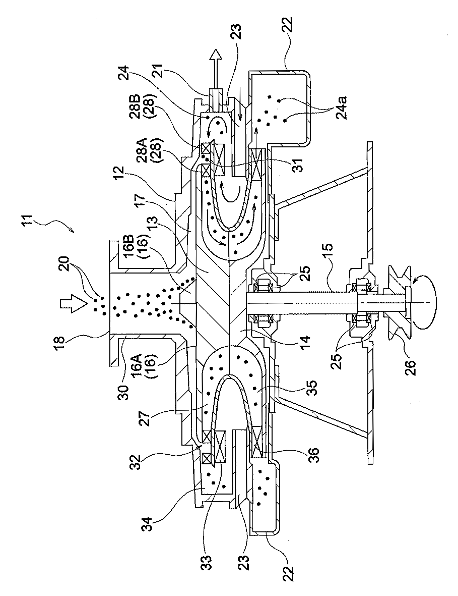
本発明に係るMg含有粒子の製造方法において、上記分級ロータを有する気流分級装置により分級を行う際の分級媒体としては、水分含有量が20質量ppm以下の乾燥気体を用いることが好ましく、未分級Mg含有粒子がオレフィン類重合用固体触媒成分である場合は、マグネシウム化合物粒子に担持させた活性チタン成分等が失活しないよう、アルゴンや窒素などの不活性ガスを用いることが好ましい。 In the method for producing Mg-containing particles according to the present invention, it is preferable to use a dry gas having a water content of 20 mass ppm or less as the classification medium when classifying by the air flow classifying device having the above-mentioned classifying rotor, and unclassified. When the Mg-containing particles are solid catalyst components for olefin polymerization, it is preferable to use an inert gas such as argon or nitrogen so that the active titanium component or the like supported on the magnesium compound particles is not deactivated.
本発明に係るMg含有粒子の製造方法において、未分級Mg含有粒子の供給量は、1〜60kg/時間が好ましく、3〜50kg/時間がより好ましく、5〜40kg/時間がさらに好ましい。 In the method for producing Mg-containing particles according to the present invention, the supply amount of unclassified Mg-containing particles is preferably 1 to 60 kg / hour, more preferably 3 to 50 kg / hour, and even more preferably 5 to 40 kg / hour.
本発明に係るMg含有粒子の製造方法において、得られるMg含有粒子(分級粒子)は、上記式(ii)により規定される粒度分布指数(SPAN)が1以下であることが好ましく、0.9以下であることがより好ましく、0.8以下であることがさらに好ましい。 In the method for producing Mg-containing particles according to the present invention, the obtained Mg-containing particles (classified particles) preferably have a particle size distribution index (SPAN) defined by the above formula (ii) of 1 or less, preferably 0.9. It is more preferably less than or equal to, and even more preferably 0.8 or less.
本発明によれば、マグネシウムを主成分として含有し、平均粒径D50(μm)が5〜100μmである未分級Mg含有粒子を、特定範囲の直径の回転体を有する遠心式気流分級装置を用いて所定条件で気流分級することにより、微粉粒子や粗粉粒子といった微粗粉粒子を除去しつつ、粒子強度の低い粗粉粒子の凝集状態を適度に解すことができ、所望粒径を有する粒子の破壊を抑制しつつその含有割合を増加させることができることから、所望の粒径を有し粒度分布の狭い分級粒子を高い収率で容易に得ることができる。 According to the present invention, unclassified Mg-containing particles containing magnesium as a main component and having an average particle size D50 (μm) of 5 to 100 μm are subjected to a centrifugal air flow classifier having a rotating body having a diameter in a specific range. By classifying the airflow under predetermined conditions, fine coarse powder particles such as fine powder particles and coarse powder particles can be removed, and the aggregated state of coarse powder particles having low particle strength can be appropriately solved, and particles having a desired particle size. Since it is possible to increase the content ratio while suppressing the destruction of the particles, it is possible to easily obtain classified particles having a desired particle size and a narrow particle size distribution in a high yield.
<オレフィン類重合体の製造方法>
次に、本発明のMg含有粒子の製造方法で製造されたMg含有粒子を用いたオレフィン類重合体の製造方法について説明する。
<Method for producing olefin polymers>
Next, a method for producing an olefin polymer using the Mg-containing particles produced by the method for producing Mg-containing particles of the present invention will be described.
オレフィン類重合体の製造方法は、本発明に係るMg含有粒子製造方法において未分級Mg含有粒子がオレフィン類重合用固体触媒成分またはオレフィン類重合触媒である場合において、得られた分級粒子を用いてオレフィン類を重合することを特徴とするものである。 In the method for producing an olefin polymer, when the unclassified Mg-containing particles are a solid catalyst component for olefin polymerization or an olefin polymerization catalyst in the method for producing Mg-containing particles according to the present invention, the obtained classified particles are used. It is characterized by polymerizing olefins.
具体的には、本発明に係るMg含有粒子製造方法において未分級Mg含有粒子がオレフィン類重合用固体触媒成分である場合には、得られた固体触媒成分を用いてオレフィン類重合触媒を形成し、係るオレフィン類重合触媒の存在下において、また、本発明に係るMg含有粒子製造方法において未分級Mg含有粒子がオレフィン類重合触媒である場合には、得られたオレフィン類重合触媒の存在下において、オレフィン類の重合を行なう。 Specifically, in the Mg-containing particle production method according to the present invention, when the unclassified Mg-containing particles are solid catalyst components for olefin polymerization, the obtained solid catalyst component is used to form an olefin polymerization catalyst. In the presence of the olefin polymerization catalyst, and when the unclassified Mg-containing particles are the olefin polymerization catalyst in the Mg-containing particle production method according to the present invention, in the presence of the obtained olefin polymerization catalyst. , Polymerize olefins.
オレフィン類重合体の製造方法において、オレフィン類としては、エチレン、プロピレン、1−ブテン、1−ペンテン、4−メチル−1−ペンテン、ビニルシクロヘキサン等から選ばれる一種以上を挙げることができ、エチレン、プロピレンまたは1−ブテンが好適であり、プロピレンがより好適である。 In the method for producing an olefin polymer, examples of the olefins include one or more selected from ethylene, propylene, 1-butene, 1-pentene, 4-methyl-1-pentene, vinylcyclohexane and the like. Propylene or 1-butene is preferred, with propylene being more preferred.
プロピレンを重合する場合、他のオレフィン類との共重合を行ってもよく、プロピレンと他のオレフィン類の単量体との共重合としては、プロピレンと少量のエチレンをコモノマーとして、1段で重合するランダム共重合と、第一段階(第一重合槽)でプロピレンの単独重合を行い、第二段階(第二重合槽)あるいはそれ以上の多段階(多段重合槽)でプロピレンとエチレン等の他のα−オレフィンとの共重合を行う、いわゆるプロピレン−エチレンブロック共重合が代表的であり、プロピレンと他のα―オレフィンとのブロック共重合が好ましい。 When propylene is polymerized, copolymerization with other olefins may be carried out, and as copolymerization of propylene and a monomer of other olefins, propylene and a small amount of ethylene are used as a comonomer and polymerized in one step. Random copolymerization and homopolymerization of propylene in the first stage (first polymerization tank), and other than propylene and ethylene in the second stage (second polymerization tank) or higher multi-step (multi-stage polymerization tank). The so-called propylene-ethylene block copolymerization, in which the above-mentioned α-olefin is copolymerized, is typical, and block copolymerization of propylene and another α-olefin is preferable.
ブロック共重合により得られるブロック共重合体とは、2種以上のモノマー組成が連続して変化するセグメントを含む重合体であり、モノマー種、コモノマー種、コモノマー組成、コモノマー含量、コモノマー配列、立体規則性などポリマーの一次構造の異なるポリマー鎖(セグメント)が1分子鎖中に2種類以上繋がっている形態のものをいう。 The block copolymer obtained by block copolymerization is a polymer containing segments in which two or more kinds of monomer compositions change continuously, and is a monomer type, a comonomer type, a comonomer composition, a comonomer content, a comonomer arrangement, and a conformational rule. It refers to a form in which two or more types of polymer chains (segments) having different primary structures such as sex are connected in one molecular chain.
共重合されるオレフィン類としては、炭素数2〜20のα−オレフィン(炭素数3のプロピレンを除く)であることが好ましく、具体的には、エチレン、1−ブテン、1−ペンテン、4−メチル−1−ペンテン、ビニルシクロヘキサン等を挙げることができ、これ等のオレフィン類は一種以上併用することができる。共重合されるオレフィン類としては、エチレンまたは1−ブテンが好適であり、エチレンが特に好適である。 The olefins to be copolymerized are preferably α-olefins having 2 to 20 carbon atoms (excluding propylene having 3 carbon atoms), and specifically, ethylene, 1-butene, 1-pentene, 4-. Examples thereof include methyl-1-pentene and vinylcyclohexane, and one or more of these olefins can be used in combination. Ethylene or 1-butene is preferable as the olefins to be copolymerized, and ethylene is particularly preferable.
オレフィン類重合体の製造方法において、オレフィン類の重合は、有機溶媒の存在下でも不存在下でも行うことができる。 In the method for producing an olefin polymer, the polymerization of olefins can be carried out in the presence or absence of an organic solvent.
また、重合対象となるオレフィン類は、気体および液体のいずれの状態でも用いることができる。 Further, the olefins to be polymerized can be used in either a gas state or a liquid state.
オレフィン類の重合は、例えば、オートクレーブ等の反応炉内において、オレフィン類重合用触媒の存在下、オレフィン類を導入し、加熱、加圧状態下に行う。 Polymerization of olefins is carried out, for example, in a reaction furnace such as an autoclave in the presence of a catalyst for olefin polymerization, in which olefins are introduced and heated and pressurized.
オレフィン類重合体の製造方法において、重合温度は、通常200℃以下であるが、100℃以下が好ましく、活性や立体規則性の向上の観点からは、60〜100℃がより好ましく、70〜90℃がさらに好ましく、75〜80℃が一層好ましい。本発明のオレフィン類重合体の製造方法において、重合圧力は、10MPa以下が好ましく、5MPa以下がより好ましい。 In the method for producing an olefin polymer, the polymerization temperature is usually 200 ° C. or lower, preferably 100 ° C. or lower, and from the viewpoint of improving activity and stereoregularity, 60 to 100 ° C. is more preferable, and 70 to 90 ° C. ℃ is more preferable, and 75 to 80 ° C is even more preferable. In the method for producing an olefin polymer of the present invention, the polymerization pressure is preferably 10 MPa or less, more preferably 5 MPa or less.
オレフィン類重合体の製造方法においては、上記重合温度範囲において、比較的高温下でホモ重合した場合でも水素活性に優れ高い立体規則性およびMFRを有する重合体を高い生産性の下で作製することができるとともに、高温下で共重合した場合においても、優れた水素活性と共重合活性を達成し、耐衝撃性に優れた共重合体を製造することができる。 In the method for producing an olefin polymer, a polymer having excellent hydrogen activity, high stereoregularity and MFR is produced under high productivity even when homopolymerized at a relatively high temperature in the above polymerization temperature range. In addition, even when copolymerized at a high temperature, excellent hydrogen activity and copolymerization activity can be achieved, and a copolymer having excellent impact resistance can be produced.
また、連続重合法、バッチ式重合法のいずれでも可能である。更に重合反応は一段で行ってもよいし、二段以上で行ってもよい。 Further, either a continuous polymerization method or a batch type polymerization method is possible. Further, the polymerization reaction may be carried out in one stage or in two or more stages.
オレフィン類重合体の製造方法において、プロピレンと他のα−オレフィン類とのブロック共重合反応は、通常、本発明に係るオレフィン類重合用触媒の存在下、前段でプロピレン単独あるいは、プロピレンと少量のα−オレフィン(エチレン等)とを接触させ、次いで後段でプロピレンとα−オレフィン(エチレン等)とを接触させることにより実施することができる。なお、上記前段の重合反応を複数回繰り返し実施してもよいし、上記後段の重合反応を複数回繰り返し多段反応により実施してもよい。 In the method for producing an olefin polymer, the block copolymerization reaction between propylene and other α-olefins is usually carried out in the presence of the olefin polymerization catalyst according to the present invention, either propylene alone or in a small amount with propylene in the previous stage. This can be carried out by contacting α-olefin (ethylene or the like) and then contacting propylene and α-olefin (ethylene or the like) in the subsequent stage. The polymerization reaction in the first stage may be repeated a plurality of times, or the polymerization reaction in the second stage may be repeated a plurality of times by a multi-step reaction.
プロピレンと他のα−オレフィン類とのブロック共重合反応は、具体的には、前段で(最終的に得られる共重合体に占める)ポリプロピレン部の割合が20〜90重量%になるように重合温度および時間を調整して重合を行ない、次いで後段において、プロピレンおよびエチレンあるいは他のα−オレフィンを導入し、(最終的に得られる共重合体に占める)エチレン−プロピレンゴム(EPR)などのゴム部割合が10〜80重量%になるように重合する。 Specifically, the block copolymerization reaction between propylene and other α-olefins is polymerized so that the proportion of the polypropylene portion (in the finally obtained copolymer) is 20 to 90% by weight in the previous stage. Polymerization is carried out by adjusting the temperature and time, and then propylene and ethylene or other α-olefins are introduced in the subsequent stage, and rubber such as ethylene-propylene rubber (EPR) (occupying the final copolymer) is introduced. Polymerize so that the proportion is 10 to 80% by weight.
前段及び後段における重合温度は共に、200℃以下が好ましく、100℃以下がより好ましく、75〜80℃がさらに好ましく、重合圧力は、10MPa以下が好ましく、5MPa以下がより好ましい。 The polymerization temperature in both the first stage and the second stage is preferably 200 ° C. or lower, more preferably 100 ° C. or lower, further preferably 75 to 80 ° C., and the polymerization pressure is preferably 10 MPa or less, more preferably 5 MPa or less.
上記共重合反応においても、連続重合法、バッチ式重合法のいずれの重合法も採用することができ、重合反応は1段で行なってもよいし、2段以上で行なってもよい。 In the above-mentioned copolymerization reaction, either a continuous polymerization method or a batch type polymerization method can be adopted, and the polymerization reaction may be carried out in one stage or in two or more stages.
また、重合時間(反応炉内の滞留時間)は、前段または後段の各重合段階のそれぞれの重合段階で、あるいは連続重合の際においても、1分〜5時間であることが好ましい。 Further, the polymerization time (residence time in the reaction furnace) is preferably 1 minute to 5 hours at each polymerization step of each polymerization step of the first stage or the second stage, or even during continuous polymerization.
重合方法としては、シクロヘキサン、ヘプタン等の不活性炭化水素化合物の溶媒を使用するスラリー重合法、液化プロピレン等の溶媒を使用するバルク重合法、実質的に溶媒を使用しない気相重合法が挙げられ、バルク重合法または気相重合法が好適であり、後段の反応は一般的にはEPRのPP粒子からの溶出を抑える目的から気相重合反応であることが好ましい。 Examples of the polymerization method include a slurry polymerization method using a solvent of an inert hydrocarbon compound such as cyclohexane and heptane, a bulk polymerization method using a solvent such as liquefied propylene, and a vapor phase polymerization method using substantially no solvent. , Bulk polymerization method or gas phase polymerization method is preferable, and the reaction in the latter stage is generally preferably a gas phase polymerization reaction for the purpose of suppressing elution of EPR from PP particles.
オレフィン類重合体の製造方法において、オレフィン類を重合(以下、適宜、本重合と称する。)するにあたり、重合対象となるオレフィン類に対してオレフィン類重合用触媒の構成成分の一部または全部を接触させることにより、予備的な重合(以下、適宜、予備重合と称する。)を行ってもよい。 In the method for producing an olefin polymer, when polymerizing olefins (hereinafter, appropriately referred to as main polymerization), some or all of the constituent components of the olefin polymerization catalyst are added to the olefins to be polymerized. Preliminary polymerization (hereinafter, appropriately referred to as prepolymerization) may be carried out by contacting them.
予備重合を行うに際して、オレフィン類重合用触媒の構成成分およびオレフィン類の接触順序は任意であるが、不活性ガス雰囲気あるいはオレフィンガス雰囲気に設定した予備重合系内に先ず有機アルミニウム化合物を装入し、次いで固体触媒成分を接触させた後、プロピレン等のオレフィン類を一種以上接触させることが好ましい。または、不活性ガス雰囲気あるいはオレフィンガス雰囲気に設定した予備重合系内に先ず有機アルミニウム化合物を装入し、次いで必要に応じ外部電子供与性化合物を接触させ、さらに固体触媒成分を接触させた後、プロピレン等のオレフィン類を一種以上接触させることが好ましい。 When performing the prepolymerization, the constituent components of the catalyst for olefin polymerization and the contact order of the olefins are arbitrary, but the organic aluminum compound is first charged into the prepolymerization system set to an inert gas atmosphere or an olefin gas atmosphere. Then, it is preferable to contact the solid catalyst component with one or more olefins such as propylene. Alternatively, the organoaluminum compound is first charged into the prepolymerization system set to an inert gas atmosphere or an olefin gas atmosphere, then an external electron donating compound is contacted if necessary, and then a solid catalyst component is contacted. It is preferable to contact one or more olefins such as propylene.
予備重合の際には、本重合と同様のオレフィン類、あるいはスチレン等のモノマーを用いることができ、予備重合条件も、上記重合条件と同様である。 At the time of prepolymerization, the same olefins or monomers such as styrene can be used as in the main polymerization, and the prepolymerization conditions are the same as the above polymerization conditions.
上記予備重合を行うことにより、触媒活性を向上させ、得られる重合体の立体規則性および粒子性状等を一層改善し易くなる。 By performing the prepolymerization, the catalytic activity is improved, and the stereoregularity and particle properties of the obtained polymer can be further improved.
オレフィン類重合体の製造方法によれば、得られるオレフィン類重合体の上記式(ii)により規定される粒度分布指数(SPAN)が、1以下であることが適当であり、0.9以下であることがより適当であり、0.8以下であることがさらに適当である。 According to the method for producing an olefin polymer, it is appropriate that the particle size distribution index (SPAN) defined by the above formula (ii) of the obtained olefin polymer is 1 or less, and 0.9 or less. It is more appropriate to be, and it is more appropriate to be 0.8 or less.
本発明のMg含有粒子の製造方法で得られたMg含有粒子を用いることにより、重合体粒子中の微粉粒子および粗粉粒子の含有量が低減された、粒度分布の狭いオレフィン類重合体の製造方法を提供することができる。 By using the Mg-containing particles obtained by the method for producing Mg-containing particles of the present invention, the content of fine powder particles and coarse powder particles in the polymer particles is reduced, and an olefin polymer having a narrow particle size distribution is produced. A method can be provided.
[Mg含有粒子分級装置の実施形態]
以下に、図1〜図4を参照して、実施形態のMg含有粒子分級装置11について説明する。Mg含有粒子分級装置11は、遠心式気流分級装置の一例である。
[Embodiment of Mg-containing particle classifier]
Hereinafter, the Mg-containing
図1に示すように、Mg含有粒子分級装置11は、全体を覆う筐体12と、筐体12内に設けられた分級ロータ13およびバランスロータ14と、分級ロータ13およびバランスロータ14を支持して回転させる回転軸15と、回転軸15を回転駆動するための図示しないモータと、筐体12の内面19と分級ロータ13の頂面16とでその外縁が規定される流路17と、を備える。
As shown in FIG. 1, the Mg-containing
本明細書において、筐体12とは、略円筒形の全体形状を有するケーシングのことをいう。筐体12は、Mg含有粒子分級装置11の外殻を構成する容器状に形成されるとともに、分級ロータ13、バランスロータ14、および回転軸15の一部の周囲を取り囲んでいる。筐体12は、円筒形の筒状部30と、筒状部30の先端部に設けられ、未分級Mg含有粒子20を投入可能な投入口18と、周側部の上部に設けられ分級処理後の製品となるMg含有粒子24の取出口21と、周側部の下部に設けられた渦巻ケーシング22と、取出口21と渦巻ケーシング22との間の位置で周側部に設けられた空気導入口23と、を備えている。投入口18には、未分級Mg含有粒子20が空気とともにMg含有粒子分級装置11内に投入される。投入口18の先端は、フランジ形に形成され、未分級Mg含有粒子20を供給する図示しない未分級Mg含有粒子供給装置に接続されている。渦巻ケーシング22は、捕集装置およびファンと接続されており、微紛24aを空気とともに除去できる。
In the present specification, the
回転軸15は、筐体12の中心に設けられている。回転軸15は、軸受け25によって回転自在に支持され、下端にはプーリ26が取り付けられている。回転軸15は、プーリ26を介してモータで回転駆動される。分級ロータ13およびバランスロータ14は、水平面内で回転可能(自転可能)に設けられている。
The rotating
分級ロータ13は、水平面内で回転する回転体の一例である。分級ロータ13は、頂面16と、内部に設けられ外縁部から中心部下方に連通する第1空洞部27と、第1空洞部27の外縁部近傍に等間隔に設けられた複数の分級羽根28と、分級羽根28同士の間の空間部分に設けられた複数の分級室31と、頂面16に設けられ分級羽根28の半径方向ほぼ中央に対応する位置に形成された複数の開口32と、分級羽根28と対向する下面に等間隔に設けられた複数の補助羽根33と、を有する。分級ロータ13およびバランスロータ14の直径は、例えば、200〜1000mmであり、300〜800mmであることが好適であり、300〜700mmであることがより好適である。複数の分級羽根28のそれぞれは、例えば、内側分級羽根28Aと、外側分級羽根28Bと、を含んでいる。
The
頂面16は、略平坦形状に形成されている。頂面16は、平坦部16Aと、平坦部16Aの中央部に設けられた円錐台形状のコーン部16Bと、を有する。コーン部16Bの内部には、分級ロータ13およびバランスロータ14が回転軸15から脱落することを阻止するピンが収納されている。
The
複数の分級羽根28のそれぞれは、分級ロータ13の半径方向に放射状に延びている。複数の開口32のそれぞれは、頂面16の外縁に沿って略環状をなすように形成されており、分級室31に向けて粉体を落下させることができる。
Each of the plurality of
補助羽根33は、分級ロータ13が回転したときに空気に回転方向の流れを与え、旋回した状態で空気を分級室31に導入できる。
The
Mg含有粒子分級装置11は、分級ロータ13の外縁部と筐体12との間に空所34を有する。取出口21は、この空所34と連通するように形成されている。
The Mg-containing
バランスロータ14は、水平面を基準に分級ロータ13と上下対称となる形状を有するとともに、分級ロータ13と略同じ重量を有する。バランスロータ14は、分級ロータ13とほぼ同様にその外縁部から中心部上方に連通する第2空洞部35と、第2空洞部35内の開口部近傍に設けられた複数の羽根36と、を有する。第2空洞部35は、中心部上方で分級ロータ13の第1空胴部27と連通するように、分級ロータ13及び回転軸15に対して一体的に固定されている。バランスロータ14の第2空洞部35の出口付近には、これを包囲するように渦巻ケーシング22が配置されている。
The
図2に示すように、流路17は、投入口18と分級室31とを結ぶ経路の一部に形成されている。流路17は、その外縁を形成する筐体12の内面19および分級ロータ13の頂面16と、それらの間に位置されて流体が流される空洞部分と、を含む概念である。図3、図4に示すように、流路17は、その上流側に位置し、投入口18を形成する筒状部30の下部内面とコーン部16Bの上端部との間に設けられた空隙である上流端部17Aと、その下流側に設けられ分級室31との境界に位置する分級室の入口31Aと、を含む。すなわち、流路17は、上流端部17Aと分級室30とを接続している。上流端部17Aは、未分級Mg含有粒子20の流れ方向における流路17の上流側の端部に相当し、且つ流路17の入口に相当する。本実施形態の流路17の断面積は、後述する参考実施形態の分級装置41の流路17に比して、大きくなっている。本実施形態では、参考実施形態の分級装置41に比して、筐体12の内面19が分級ロータ13の頂面16から離間した位置に配置されている。
As shown in FIG. 2, the
流路17は、筐体12の内面19と分級ロータ13の頂面16とで規定される空間内に形成され、投入口18を中心に外側に広がる略円盤形に形成されている。筐体12は、頂面16の平坦部16Aに対向する位置で筐体12に設けられた第1部分12Aと、頂面16の平坦部16Aに対向する位置で且つ第1部分12Aよりも投入口18側(内側)で筐体12に設けられた第2部分12Bと、頂面16のコーン部16Bに対向する位置で筐体12に設けられた第3部分12Cと、を有する。第1部分12Aは、頂面16(平坦部16A)から第1の所定距離を離間している。第1の所定距離は、例えば、図2中に寸法dで示され、例えば、6〜15mmであり、8〜12mmであることがさらに好ましい。
The
第2部分12Bは、第1の所定距離よりも大きい第2の所定距離以上頂面16(平坦部16A)から離間している。第2の所定距離は、例えば、図2中に寸法cで示される。第2部分12Bは、寸法c>寸法dの関係を満たすように形成される。第2の所定距離は、例えば、11〜16mmであり、12〜15mmであることがさらに好ましい。
The
第2部分12Bは、分級ロータ13の中心方向に近づくにつれて(投入口18に近づくにつれて)頂面16から遠ざかるように斜めになっている。第2部分12Bのうち頂面16から最も遠ざかった部分と頂面16(平坦部16A)との間の距離は、図2中に寸法bで示され、例えば、17〜22mmであり、18〜21mmであることがさらに好ましい。
The
第3部分12Cは、コーン部16Bに対向する位置で流路17内にエッジを生じないように、角部を面取りするように形成されている。第3部分12Cは、コーン部16Bの側面に沿うように略平行に形成されている。第3部分12Cとコーン部16Bの側面との間の距離は、図2中に寸法aで示され、例えば、14〜19mmであり、15〜18mmであることがさらに好ましい。
The
流路17は、上記のように第3部分12Cおよび第2部分12Bに対応する箇所で断面積を比較的に大きくするように形成されている。このため、流体力学の連続の式より、この流路17の内部を流れる未分級Mg含有粒子20の上流端部17Aにおける平均流速よりも、流路17中の上流端部17Aよりも下流側における未分級Mg含有粒子20の平均流速を小さくすることができる。
The
より具体的には、流路17は、分級室31の入口31Aにおける未分級Mg含有粒子20の平均流速を上流端部17Aにおける未分級Mg含有粒子20の平均流速の半分以下に減少できる。また、流路は、分級ロータ13(分級ロータ13の頂面16)の半径の略中間位置における未分級Mg含有粒子20の平均流速を、上流端部17Aにおける未分級Mg含有粒子20の平均流速の2/3以下に低減できる。したがって、本実施形態のMg含有粒子分級装置11の流路17は、前半部分(第2部分12Bおよび第3部分12C)で未分級Mg含有粒子20の流速を大きく低下させることができる。さらに、流路17は、分級室31の入口31Aにおける未分級Mg含有粒子20の平均流速を例えば15m/s以下にできる。
また、Mg含有粒子分級装置11は、未分級Mg含有粒子20中に含まれる粒径5μm未満の微粉粒子(Mg含有粒子以外の粒子)を除去できる。分級時に微粉として除去する粒子の粒子径(カットポイント)は、5μm以上かつ未分級Mg含有粒子20の平均粒径(D50)以下の範囲であると共に、分級ロータ13の寸法、分級ロータ13の回転数、流路17の寸法、渦巻ケーシング22に接続するファンのサイズ、その他の条件を上記範囲内で設定することで適宜に調整できる。これによって、Mg含有粒子分級装置11は、除去対象の微粉粒子(例えば、粒径5μm未満の微粉粒子)を確実に除去できる。なお、微粉粒子の粒径は、上記式(A)により算出することができ、0.1〜100.0μmの範囲で適宜設定することができる。
More specifically, the
Further, the Mg-containing
続いて、図1〜図4を参照して、本実施形態のMg含有粒子分級装置11の作用およびMg含有粒子の製造方法について説明する。
Subsequently, with reference to FIGS. 1 to 4, the operation of the Mg-containing
モータの駆動により分級ロータ13およびバランスロータ14を所定の速度で回転させる。分級ロータ13の回転速度は、上記分級工程で記載した通りである。
The
渦巻ケーシング22に連結されたファンで筐体12の内部に負圧を生じさせる。これによって、矢印で示すように空気導入口23から空気が吸引され、この吸引によって流入された空気は補助羽根33によって分級ロータ13の回転方向の流れに変換される。空所34内において、分級ロータ13の回転方向に沿って旋回する空気は、分級室31内に向けて流れる空気流を形成する。分級室31に入った空気は、分級羽根28に沿って移動し、矢印で示すように分級ロータ13の第1空洞部27とバランスロータ14の第2空洞部35とを通過し、渦巻ケーシング22を介して筐体12外に吸引される。これと同時に、筐体12の内部の負圧は、投入口18から流路17を通り分級室31まで至る空気流を形成する。
A fan connected to the
この状態で、投入口18から未分級Mg含有粒子20を投入することで、Mg含有粒子24の分級(製造)を行うことができる。すなわち、投入口18から空気とともに投入された未分級Mg含有粒子20は、空気流に乗り、流路内を通過する間に分級ロータ13の軸心を中心とする放射方向にほぼ均一に分散され、未分級Mg含有粒子20の一次分散が行われる。このように分級室31に未分級Mg含有粒子20を供給する工程において、分級室31の入口31Aにおける未分級Mg含有粒子20の平均流速は、上流端部17Aにおける未分級Mg含有粒子20の平均流速の半分以下に低減される。また、この分級室31に未分級Mg含有粒子20を供給する工程において、分級ロータ13の半径の略中間位置における未分級Mg含有粒子20の平均流速は、上流端部17Aにおける未分級Mg含有粒子20の流速の2/3以下に低減される。そして、分級室31の入口31Aにおける未分級Mg含有粒子20の平均流速は、15m/s以下である。頂面16の外縁から外側に出た未分級Mg含有粒子20は分級ロータ13の回転に伴い分級ロータ13の外縁の接線方向に放射され、二次分散される。
In this state, the unclassified Mg-containing
投入口18に投入される未分級Mg含有粒子20は、一次粒子同士が結合して塊となった二次粒子を形成している場合が多い。この一次分散および二次分散では、未分級Mg含有粒子20の二次粒子が分級ロータ13の頂面16や筐体12の内面19等に衝突することで適度にほぐされて、一次粒子の形にまで解砕される。その際、流路17において、分級室31に供給される際の未分級Mg含有粒子20の流速が十分に低下されているために、分級室31に供給される前に未分級Mg含有粒子20が筐体12の内面19や分級ロータの頂面16等に衝突して壊れてしまうことが防止される。
In many cases, the unclassified Mg-containing
一次粒子の形にまで解砕された未分級Mg含有粒子20は、開口32を通して分級室31に供給される。ここで未分級Mg含有粒子20は分級ロータ13の回転による遠心力と半径方向に流れる空気による抗力を受ける。未分級Mg含有粒子20のうち、遠心力>抗力の関係が成り立つ分級処理後のMg含有粒子24(製品)は分級ロータ13の外周囲の空所内に飛ばされ、取出口21からMg含有粒子分級装置11の外に取り出される。また遠心力<抗力の関係が成り立つ粒径の小さい微紛24aは半径方向の空気流に乗った状態で、分級ロータ13の第1空洞部27およびバランスロータ14の第2空洞部35を介して渦巻ケーシング22に送られる。微紛24aは、渦巻ケーシング22に接続された捕集装置により捕集・除去される。
The unclassified Mg-containing
本実施形態によれば、以下のことがいえる。Mg含有粒子分級装置11は、投入口18を有する筐体12内で投入口18の下方に設けられ、回転する分級ロータ13外縁側に位置する分級室31で未分級Mg含有粒子20を分級してMg含有粒子24aを得るMg含有粒子分級装置であって、筐体12と分級ロータ13の頂面16とで規定されるとともに投入口18と分級室31とを接続する流路17であって、内部を流れる未分級Mg含有粒子20の流速を減少させる流路17を備える。
According to this embodiment, the following can be said. The Mg-containing
Mg含有粒子の製造方法は、筐体12の内面と筐体12内で回転する回転体の頂面16とで形成され上流端部17Aと回転体の外縁側に位置する分級室31とを接続する流路17の内部を流れる未分級Mg含有粒子20の上流端部17Aにおける平均流速よりも、流路17中の上流端部17Aよりも下流側における未分級Mg含有粒子20の平均流速を小さくして分級室31に未分級Mg含有粒子20を供給する工程と、分級室31で未分級Mg含有粒子20を分級してMg含有粒子24aを得る工程と、を備え、下記式(1)により求められる未分級Mg含有粒子20の磨滅耐久度A(%)が85以下である。
A=(Z÷Y)×100 … (1)
(式中、Yは、レーザ回折式粒子径分布測定装置を用い送風圧0.4バールにおいて乾式自動測定される平均粒径D50(μm)を、Zは、前記レーザ回折式粒子径分布測定装置を用い送風圧1.0バールにおいて乾式自動測定される平均粒径D50(μm)を、それぞれ示す。)
The method for producing Mg-containing particles is to connect the
A = (Z ÷ Y) × 100… (1)
(In the formula, Y is the average particle size D 50 (μm) automatically measured dry at a blowing pressure of 0.4 bar using a laser diffraction type particle size distribution measuring device, and Z is the laser diffraction type particle size distribution measurement. The average particle size D 50 (μm) automatically measured dry at a blowing pressure of 1.0 bar using the device is shown.)
これらの構成によれば、流路17において未分級Mg含有粒子20の流速を十分に減少できるため、未分級Mg含有粒子20が分級室31に供給される前に筐体12の内面19等に衝突した場合でも、衝突時のエネルギーを低減することができる。これによって、未分級Mg含有粒子20の二次粒子を一次粒子になるように適度に解砕しつつ、未分級Mg含有粒子20が望ましい一次粒子の形からさらに細かく破壊されてしまうことを防止できる。これによって、分級処理後のMg含有粒子24の歩留まりを向上することができる。また、上記の構成によれば、いわゆる壊れやすい未分級Mg含有粒子20を用いる場合でも、当該未分級Mg含有粒子20の破損を防止して分級処理後のMg含有粒子24の歩留まりを向上できる。
According to these configurations, the flow velocity of the unclassified Mg-containing
この場合、Mg含有粒子分級装置11の流路17およびMg含有粒子の製造方法における分級室31に未分級Mg含有粒子20を供給する工程は、分級室31の入口31Aにおける未分級Mg含有粒子20の平均流速を上流端部17Aにおける未分級Mg含有粒子20の平均流速の半分以下に減少させる。この構成によれば、筐体12の内面19等に衝突する際のエネルギーを低減でき、Mg含有粒子24が望ましい一次粒子の形からさらに細かく破壊されてしまうことを防止できる。これによって、分級処理後のMg含有粒子24の歩留まりを向上することができる。
In this case, in the step of supplying the unclassified Mg-containing
分級室31に未分級Mg含有粒子20を供給する工程において、分級ロータ13の頂面16の半径の略中間位置における未分級Mg含有粒子20の平均流速は、上流端部17Aにおける未分級Mg含有粒子20の平均流速の2/3以下である。この構成によれば、流路17の前半において流路17を流れる未分級Mg含有粒子20の流速を大きく低減させることができる。これによって、流路17の後半において未分級Mg含有粒子20が筐体の内面19に衝突することがあっても、衝突時のエネルギーを大きく低減することができる。このため、例えば、流路17の後半で未分級Mg含有粒子20の流速を低減するような構造に比して、分級処理後のMg含有粒子24の歩留まりをさらに向上することができる。
In the step of supplying the unclassified Mg-containing
この場合、Mg含有粒子分級装置11の流路17およびMg含有粒子の製造方法における分級室31に未分級Mg含有粒子20を供給する工程は、分級室31の入口31Aにおける未分級Mg含有粒子20の平均流速を15m/s以下に減少させる。この構成によれば、分級室31に供給される直前の未分級Mg含有粒子20の流速を抑えることで、未分級Mg含有粒子20が筐体12の内面19に衝突することがあっても、衝突時のエネルギーを小さくすることができる。これによって、Mg含有粒子分級装置11によって製造される分級されたMg含有粒子24の歩留まりを著しく向上することができる。
In this case, the step of supplying the unclassified Mg-containing
筐体12は、頂面16に対向する位置で筐体12に設けられ頂面16から第1の所定距離を離間した第1部分12Aと、頂面16に対向する位置で且つ第1部分12Aよりも投入口18側で筐体12に設けられ、前記第1の所定距離よりも大きい第2の所定距離以上を頂面16から離間した第2部分12Bと、を有する。
The
この構成によれば、投入口18に近い第2部分12Bに対応する位置で、流路17の断面積を大きくすることで、流路27の上流側で流路17を通過する未分級Mg含有粒子20の流速を大きく低減することができる。これによって、流路17の下流側で未分級Mg含有粒子20が筐体12の内面19に衝突することがあっても、衝突時のエネルギーを小さくすることができる。このため、Mg含有粒子分級装置11によって製造される分級されたMg含有粒子24の歩留まりを著しく向上することができる。
According to this configuration, by increasing the cross-sectional area of the
第2部分12Bは、投入口18に近づくにつれて頂面16から遠ざかるように斜めになっている。この構成によれば、流路17の断面積を投入口18側に近づくにつれて徐々に大きくすることができる。これによって、投入口18に近い側で積極的に未分級Mg含有粒子20の流速を低下させることができる。このため、流路17の下流側において未分級Mg含有粒子20が筐体12の内面19に衝突することがあっても、衝突時のエネルギーを小さくすることができる。なお、この構成によれば、見かけ上、流路17の断面積は、投入口18から遠くなるにつれて小さくなるように思われるが、実際には、流路17が投入口18を中心に放射状に広がっているために、投入口18から遠ざかるにつれて実際に流路17の断面積が大きく減少することはない。
The
この場合、頂面16は、略平坦形状に形成される。従来の分級装置では、分級ロータ13の頂面16に分散羽根が設けられ、分散羽根によって粒子の分散を行われていた。これによって、粒子の分散および解砕を効率化できたが、分散羽根による空気の送り出し作用によって、頂面16の外縁に向かう粒子の加速を促進していた。発明者らは、分散羽根による粒子の加速が、筐体12の内面19や分級ロータ13の頂面16等に未分級Mg含有粒子20が衝突した際のエネルギーが増大させ、その結果として未分級Mg含有粒子20が破損して分級後のMg含有粒子24の歩留まりを悪化させることを問題点として見出した。上記の構成によれば、分級ロータ13の頂面16に分散羽根等の突起物が設けられることがない。このため、分散羽根を設けた場合に比して、未分級Mg含有粒子20の流速を抑えることができる。これによって、未分級Mg含有粒子20が筐体の内面19等に衝突した際のエネルギーを低減し、分級処理後のMg含有粒子24の歩留まりを向上できる。
In this case, the
この場合、前記略平坦形状は、投入口18に対向する位置に錐台形のコーン部16Bを含む。この構成によれば、流路17の投入口18近傍において、流路17の断面積を大きく確保することができる。これによって、投入口18に近い側で積極的に未分級Mg含有粒子20の流速を低下させることができ、それによって分級処理後のMg含有粒子24の歩留まりを向上できる。
In this case, the substantially flat shape includes a cone-shaped
上記した実施形態は、種々の置き換えや変形を加えて実施できる。また、上記実施形態同士を適宜に組み合わせて発明を実現することも当然にできる。
(参考実施形態)
The above-described embodiment can be implemented with various replacements and modifications. In addition, it is naturally possible to realize the invention by appropriately combining the above embodiments.
(Reference embodiment)
図5〜図8を参照して、参考実施形態の分級装置41について説明する。以下の説明では、主として上記実施形態のMg含有粒子分級装置11との相違点を中心に説明する。
The
参考実施形態の分級装置41は、全体を覆う筐体12と、筐体12内に設けられた分級ロータ13およびバランスロータ14と、分級ロータ13およびバランスロータ14を支持して回転させる回転軸15と、回転軸15を回転駆動するための図示しないモータと、筐体12と分級ロータ13の頂面16とで規定される流路17と、を備える。
The
図5〜図8に示すように、分級ロータ13は、頂面16に複数の分散羽根42を有する。複数の分散羽根42は、頂面16の平坦部16Aから上方に向けて起立しており、分級ロータ13の半径方向に沿って延びている。複数の分散羽根42は、互いに分離している。頂面16のコーン部16Bは、円錐形状に形成されている。筐体12に設けられた投入口18は、その内側の流路17の断面積が途中で小さくなるように、くびれ部43が設けられている。
As shown in FIGS. 5 to 8, the
参考実施形態の分級装置41の作用について説明する。参考実施形態の分級装置41は、上記実施形態のMg含有粒子分級装置11と同様に、筐体12の内部に生成した負圧によって、投入口18から流路17を通り分級室31まで至る空気流が形成される。投入口18から未分級Mg含有粒子20が投入されると、この空気流に乗って未分級Mg含有粒子20が分級室31まで供給される。その際、未分級Mg含有粒子20は、分散羽根42同士の間の隙間44Aを通って流路17内を通過したり、分散羽根42と筐体12の内面19との間の隙間44Bを通って流路17内を通過したりする。このように比較的に狭い空間を通ることで、未分級Mg含有粒子20の流速が大きいままで維持される。特に、分散羽根42の間の隙間44Aを通る粒子は、分散羽根42による空気の送り出し作用(ファンの作用)によって、流速が著しく増大する。
The operation of the
参考実施形態の分級装置41では、分級室31に入る際の未分級Mg含有粒子20の流速が著しく速く、その結果、分級室31に入るまでに筐体12の内面19や分級ロータ13の頂面16や分散羽根42に衝突して、その衝突時に衝撃によって未分級Mg含有粒子20が破損してしまう。このため、参考実施形態の分級装置41では、分級処理後のMg含有粒子24の歩留まりが悪化する。また、参考実施形態の分級装置41では、壊れやすい未分級Mg含有粒子20を用いた場合に、歩留まり悪化の問題がさらに顕在化する。
In the
(実施例A1)
上記実施形態で説明したMg含有粒子分級装置11の実施例A1について説明する。実施例A1では、上記実施形態で説明したMg含有粒子分級装置11の流路17を模して、これを通る未分級Mg含有粒子の流速を流体解析ソフトウェアを用いて解析した。CAD形状作成にはANSYS SCDM、流速の解析にはANSYS Fluentを使用した。実際の解析作業は、客観性を担保するために、出願人とは無関係の第三者機関(サイバネットシステム株式会社)に業務委託して行った。
(Example A1)
Example A1 of the Mg-containing
実施例A1のMg含有粒子分級装置の解析モデルは、流路17の各部の寸法を図2に示す寸法a=17.3mm、寸法b=19mm、寸法c=13.97mm、寸法d=11mmで設定した。また、分級ロータ13の直径を380mmとした。投入口18に対する未分級Mg含有粒子の投入量を5.611×10⁻³kg/sとし、投入口18の空気の流量を0.190049kg/sとした。分級ロータ13の回転数を1350rpmとした。分級室31圧力(出口圧力)を0.0Paとした(ゲージ圧で大気開放を模擬)。作動流体は、圧縮性を考慮した流体である窒素とした。未分級Mg含有粒子の密度を2060kg/m3、未分級Mg含有粒子の粒子径4.13×10−5mとした。筐体12および分級ロータ13に対する未分級Mg含有粒子の反発係数を0.1とした。
In the analysis model of the Mg-containing particle classifier of Example A1, the dimensions of each part of the
解析の結果、各部における未分級Mg含有粒子の流速は以下であった。図3に示すA−A線の位置での未分級Mg含有粒子の平均流速は26.342m/sであり、B−B線の位置での未分級Mg含有粒子の平均流速は34.184m/sであった。図4に示すC−C線の位置での未分級Mg含有粒子の平均流速は30.713m/sであり、D−D線の位置での未分級Mg含有粒子の平均流速は20.939m/sであり、E−E線の位置での未分級Mg含有粒子の平均流速は20.434m/sであり、F−F線の位置での未分級Mg含有粒子の平均流速は12.677m/sであった。結果を表1に示す。単位は、m/sである。 As a result of the analysis, the flow velocities of the unclassified Mg-containing particles in each part were as follows. The average flow velocity of the unclassified Mg-containing particles at the position of the AA line shown in FIG. 3 is 26.342 m / s, and the average flow velocity of the unclassified Mg-containing particles at the position of the BB line is 34.184 m / s. It was s. The average flow velocity of the unclassified Mg-containing particles at the position of the CC line shown in FIG. 4 is 30.713 m / s, and the average flow velocity of the unclassified Mg-containing particles at the position of the DD line is 20.939 m / s. The average flow velocity of the unclassified Mg-containing particles at the position of the EE line is 20.434 m / s, and the average flow velocity of the unclassified Mg-containing particles at the position of the FF line is 12.677 m / s. It was s. The results are shown in Table 1. The unit is m / s.
したがって、実施例A1では、投入口18から流路17を通り分級室31に行くにつれて、未分級Mg含有粒子の平均流速が徐々に低下する。特に、分級室31の入口31A(F−F線の位置)の未分級Mg含有粒子の平均流速は、上流端部17A(B−B線の位置)における未分級Mg含有粒子の平均流速の半分以下に低減されていることが理解できる。また、分級室31の入口31A(F−F線の位置)の未分級Mg含有粒子の平均流速は15m/s以下に抑えられている。
Therefore, in Example A1, the average flow velocity of the unclassified Mg-containing particles gradually decreases as the
さらに、分級ロータ13の半径の略中間位置(E−E線の位置)での未分級Mg含有粒子の平均流速は、上流端部17A(B−B線の位置)における未分級Mg含有粒子の平均流速の2/3以下に低減されている。このため、実施例A1のMg含有粒子分級装置11では、流路17の上流側で未分級Mg含有粒子の平均流速が大きく低減されることが理解できる。
Further, the average flow velocity of the unclassified Mg-containing particles at a substantially intermediate position (position of the EE line) of the radius of the classifying
(比較例A1)
比較例A1では、上記参考実施形態で説明した分級装置41の流路17を模して、これを通る未分級Mg含有粒子の流速を流体解析ソフトウェアを用いて解析した。CAD形状作成にはANSYS SCDM、流速の解析にはANSYS Fluentを使用した。実際の解析作業は、客観性を担保するために、出願人とは無関係の第三者機関(サイバネットシステム株式会社)に業務委託して行った。
(Comparative Example A1)
In Comparative Example A1, the flow velocity of the unclassified Mg-containing particles passing through the
比較例A1の分級装置41の解析モデルは、流路17の各部の寸法を図5〜図8に示される実機を模して設定した。すなわち、図5に示す寸法a=11mm、寸法b=5.97mm、寸法c=1mm、寸法d=3.25mmで設定した。投入口18は最大口径となる部分よりも内径が小さくなったくびれ部43を有しており、くびれ部43の内径は50mmとし、投入口18の最大口径となる部分の内径は90mmとした。分散羽根同士の隙間の幅を6mmとした。
In the analysis model of the
また、分級ロータ13の直径を380mmとした。投入口18に対する未分級Mg含有粒子の投入量を5.611×10⁻³kg/sとし、投入口18の空気の流量を0.190049kg/sとした。分級ロータ13の回転数を1350rpmとした。分級室圧力(出口圧力)を0.0Paとした(ゲージ圧で大気開放を模擬)。作動流体は、圧縮性を考慮した流体である窒素とした。未分級Mg含有粒子の密度を2060kg/m3、未分級Mg含有粒子の粒子径4.13×10−5mとした。筐体12および分級ロータ13に対する未分級Mg含有粒子の反発係数を0.1とした。
Further, the diameter of the
解析の結果、各部における未分級Mg含有粒子の流速は以下であった。図6に示すA−A線の位置での未分級Mg含有粒子の平均流速は63.563m/sであり、B−B線の位置での未分級Mg含有粒子の平均流速は56.237m/sであった。図7に示すC−C線の位置での未分級Mg含有粒子の平均流速は41.187m/sであり、D−D線の位置での未分級Mg含有粒子の平均流速は71.931m/sであり、E−E線の位置での未分級Mg含有粒子の平均流速は120.161m/sであり、F−F線の位置での未分級Mg含有粒子の平均流速は43.439m/sであった。結果を表1に示す。 As a result of the analysis, the flow velocities of the unclassified Mg-containing particles in each part were as follows. The average flow velocity of the unclassified Mg-containing particles at the position of the AA line shown in FIG. 6 is 63.563 m / s, and the average flow velocity of the unclassified Mg-containing particles at the position of the BB line is 56.237 m / s. It was s. The average flow velocity of the unclassified Mg-containing particles at the position of the CC line shown in FIG. 7 is 41.187 m / s, and the average flow velocity of the unclassified Mg-containing particles at the position of the DD line is 71.931 m / s. The average flow velocity of the unclassified Mg-containing particles at the position of the EE line is 120.161 m / s, and the average flow velocity of the unclassified Mg-containing particles at the position of the FF line is 43.439 m / s. It was s. The results are shown in Table 1.
また、D−D線の位置およびE−E線の位置では、分散羽根42同士の間の位置(隙間44A)と、分散羽根42と筐体12との間の位置(隙間44B)で平均流速が異なっていた。D−D線の位置での分散羽根42同士の間の位置の平均流速は、76.262m/sであり、D−D線の位置での分散羽根42と筐体12の間の位置の平均流速は、43.419m/sであった。E−E線の位置での分散羽根42同士の間の位置の平均流速は、136.431m/sであり、E−E線の位置での分散羽根42と筐体12の間の位置の平均流速は、101.533m/sであった。結果を表2に示す。単位は、m/sである。
Further, at the positions of the DD line and the EE line, the average flow velocity is at the position between the dispersion blades 42 (
したがって、比較例A1では、くびれ部43の近傍位置(A−A線の位置)ですでに未分級Mg含有粒子の流速が実施例A1に比して高くなっている。 Therefore, in Comparative Example A1, the flow velocity of the unclassified Mg-containing particles is already higher than that in Example A1 at the position near the constricted portion 43 (the position of the AA line).
比較例A1では、分散羽根42による空気の送り出し作用によって、C―C線の位置からD−D線の位置まで区間で未分級Mg含有粒子が加速され、D―D線の位置からE−E線の位置まで区間で未分級Mg含有粒子がさらに加速されている。したがって、比較例A1では、分散羽根42の外側の位置での未分級Mg含有粒子の流速が、投入口18近傍位置での未分級Mg含有粒子の流速の2倍程度にまで加速されたことが理解される。
In Comparative Example A1, the unclassified Mg-containing particles are accelerated in the section from the position of the CC line to the position of the DD line by the air feeding action of the
さらに、表2の結果から、分散羽根42同士の間の位置(隙間44A)のほうが、分散羽根42と筐体12の間の位置(隙間44B)よりも、分散羽根42による空気の送り出し作用で未分級Mg含有粒子の流速が大きく増大することが理解される。
Further, from the results in Table 2, the position between the dispersion blades 42 (
(製造例1)
<固体触媒成分の調製>
特許第6515038号(実施例1)に記載の固体触媒成分の調製方法に準拠し、粉末状の固体触媒成分(未分級品)N1を約60kg得た。
(Manufacturing Example 1)
<Preparation of solid catalyst components>
According to the method for preparing a solid catalyst component described in Japanese Patent No. 6515038 (Example 1), about 60 kg of a powdery solid catalyst component (unclassified product) N1 was obtained.
具体的には、攪拌装置を備え、窒素ガスで置換された内容積500mLのフラスコに、ジエトキシマグネシウム10g(87.4ミリモル)、トルエン55mL、四塩化チタン30mL、(2−エトキシエチル)エチルカーボネート(A)9ミリモル(1.46g)、2−イソプロピル−2−イソペンチル−1,3−ジメトキシプロパン(B)1.2ミリモル(0.26g)を加え、温度100℃で90分反応させた。反応終了後、反応生成物を100℃のトルエン75mLで4回洗浄した。次に、新たに四塩化チタン10容量%のトルエン溶液100mLを加えて、100℃に昇温し、15分間攪拌し反応させ、反応後、生成物を100℃のトルエンで1回洗浄した。この操作をさらに2回行った後、40℃のn−ヘプタン75mLで6回洗浄し、残留溶媒を減圧乾燥により除去して固体触媒成分(未分級品)N1を得た。 Specifically, a flask equipped with a stirrer and having an internal volume of 500 mL replaced with nitrogen gas is filled with 10 g (87.4 mmol) of diethoxymagnesium, 55 mL of toluene, 30 mL of titanium tetrachloride, and (2-ethoxyethyl) ethyl carbonate. (A) 9 mmol (1.46 g) and 1.2 mmol (0.26 g) of 2-isopropyl-2-isopentyl-1,3-dimethoxypropane (B) were added, and the mixture was reacted at a temperature of 100 ° C. for 90 minutes. After completion of the reaction, the reaction product was washed 4 times with 75 mL of toluene at 100 ° C. Next, 100 mL of a new toluene solution of 10% by volume of titanium tetrachloride was added, the temperature was raised to 100 ° C., and the mixture was stirred for 15 minutes for reaction. After the reaction, the product was washed once with toluene at 100 ° C. After performing this operation two more times, the mixture was washed 6 times with 75 mL of n-heptane at 40 ° C., and the residual solvent was removed by drying under reduced pressure to obtain a solid catalyst component (unclassified product) N1.
得られた固体触媒成分(未分級品)N1の粒度分布を測定した。結果を表3に示す。なお、この固体触媒成分(未分級品、未分級Mg含有粒子)N1の摩滅耐久度を測定した所、73%であった。 The particle size distribution of the obtained solid catalyst component (unclassified product) N1 was measured. The results are shown in Table 3. The abrasion durability of this solid catalyst component (unclassified product, unclassified Mg-containing particles) N1 was measured and found to be 73%.
<固体触媒成分の摩滅耐久度の計算方法>
乾式粉体分散ユニット(スペクトリス(株)製、Aero S)を具備したレーザ回折式粒子径分布測定装置(スペクトリス(株)製、マスターサイザー3000)を用い、得られた固体触媒成分の粒度分布を、送風圧0.4バールと1.0バールでそれぞれ自動測定し、得られたD50値から下記式(1)により摩滅耐久度A(%)を算出した。
<Calculation method of abrasion durability of solid catalyst component>
Using a laser diffraction type particle size distribution measuring device (manufactured by Spectris Co., Ltd., Mastersizer 3000) equipped with a dry powder dispersion unit (manufactured by Spectris Co., Ltd., Aero S), the particle size distribution of the obtained solid catalyst component was measured. , measured automatically respectively feeding air pressure 0.4 bar and 1.0 bar, wear durability a (%) by the following equation from the obtained D 50 value (1) was calculated.
磨滅耐久度A(%)=(Z÷Y)×100 … (1)
(式中、Yは、レーザ回折式粒子径分布測定装置を用い送風圧0.4バールにおいて乾式自動測定される平均粒径D50(μm)を、Zは、前記レーザ回折式粒子径分布測定装置を用い送風圧1.0バールにおいて乾式自動測定される平均粒径D50(μm)を、それぞれ示す。)
Abrasion durability A (%) = (Z ÷ Y) × 100… (1)
(In the formula, Y is the average particle size D 50 (μm) automatically measured dry at a blowing pressure of 0.4 bar using a laser diffraction type particle size distribution measuring device, and Z is the laser diffraction type particle size distribution measurement. The average particle size D 50 (μm) automatically measured dry at a blowing pressure of 1.0 bar using the device is shown.)
<固体触媒成分の粒度分布および平均粒径の計算方法>
レーザ光散乱回折式粒度測定機(MT−3300EX:日機装(株)社製)を用い、固体触媒成分の粉末を、予めトリデシルアルミニウムを添加したn−ヘプタン溶媒中に、該固体触媒成分が0.05g〜0.20gの範囲で装置が示す最適分散濃度範囲に含まれるよう投入し、体積基準積算粒度を自動測定により求め、また、粒度分布指数(SPAN)を下記の式(ii)により算出した。平均粒径としては、D50の値を用いた。その結果を表3に示す。
<Calculation method of particle size distribution and average particle size of solid catalyst components>
Using a laser light scattering diffraction type particle size analyzer (MT-3300EX: manufactured by Nikkiso Co., Ltd.), the powder of the solid catalyst component was put into an n-heptane solvent to which tridecyl aluminum was added in advance, and the solid catalyst component was 0. The particle size is added so that it is included in the optimum dispersion concentration range indicated by the device in the range of .05 g to 0.20 g, the volume-based integrated particle size is obtained by automatic measurement, and the particle size distribution index (SPAN) is calculated by the following formula (ii). did. The average particle size was used the value of D 50. The results are shown in Table 3.
粒度分布指数(SPAN)=(D90−D10)/D50 …(ii)
(D10、D50およびD90は、各々、上記測定機を用いて測定したときの体積基準積算粒度で10%の粒径、50%の粒径および90%の粒径を意味する。)
なお、各粒子の粒径は、周囲長径、すなわち、各粒子の投影像の周囲長と同一の周囲長を有する円を仮定し、その直径を求めることにより自動で算出されたものである。
Particle size distribution index (SPAN) = (D 90- D 10 ) / D 50 ... (ii)
(D 10 , D 50 and D 90 mean a particle size of 10%, a particle size of 50% and a particle size of 90%, respectively, in terms of volume-based integrated particle size when measured using the above measuring machine.)
The particle size of each particle is automatically calculated by assuming a peripheral major axis, that is, a circle having the same peripheral length as the peripheral length of the projected image of each particle, and obtaining the diameter.
(製造例2)
<固体触媒成分の調製>
特許第6343561号(実施例11)に記載されている固体触媒成分の調製方法に準拠して、粉末状の固体触媒成分N2(未分級品)を約60kg得た。
(Manufacturing Example 2)
<Preparation of solid catalyst components>
According to the method for preparing a solid catalyst component described in Japanese Patent No. 6345561 (Example 11), about 60 kg of a powdery solid catalyst component N2 (unclassified product) was obtained.
具体的には、攪拌装置を備え、窒素ガスで置換された内容積500mLの丸底フラスコに四塩化チタン70mL、トルエン70mLを装入して混合溶液を形成し、液温を−10℃に保持した。次いで、攪拌装置を備え、窒素ガスで置換された内容積200mLの丸底フラスコに、ジエトキシマグネシウム(平均粒径54μm)20g、トルエン70mL、エタノール0.25mL(ジエトキシマグネシウム100質量部に対して1.0質量部)を装入して懸濁液を形成し、さらにフタル酸ジ−n−ブチル26.3ミリモル(7.0mL)を添加した。この懸濁液を、予め液温−10℃に保持しておいた前記の混合溶液中に全量添加した後、フラスコ内温を−10℃から110℃まで昇温し、110℃において3時間攪拌しながら反応させた。反応終了後、得られた固体生成物を100℃のトルエン167mLで4回洗浄した。その後、新たに常温のトルエン123mL、四塩化チタン20mLを添加し110℃まで昇温し、2時間攪拌しながら反応させ、反応終了後、上澄みを除去した後、40℃のn−ヘプタン125mLで8回洗浄することにより、固体触媒成分(未分級品)N2を得た。 Specifically, a stirring device is provided, and 70 mL of titanium tetrachloride and 70 mL of toluene are charged into a round-bottom flask having an internal volume of 500 mL replaced with nitrogen gas to form a mixed solution, and the liquid temperature is maintained at -10 ° C. did. Next, a round-bottom flask equipped with a stirrer and having an internal volume of 200 mL replaced with nitrogen gas was charged with 20 g of diethoxymagnesium (average particle size 54 μm), 70 mL of toluene, and 0.25 mL of ethanol (relative to 100 parts by mass of diethoxymagnesium). 1.0 part by mass) was charged to form a suspension, and 26.3 mmol (7.0 mL) of di-n-butyl phthalate was further added. After adding the entire amount of this suspension to the mixed solution previously kept at a liquid temperature of −10 ° C., the temperature inside the flask is raised from −10 ° C. to 110 ° C. and stirred at 110 ° C. for 3 hours. It reacted while. After completion of the reaction, the obtained solid product was washed 4 times with 167 mL of toluene at 100 ° C. Then, 123 mL of toluene at room temperature and 20 mL of titanium tetrachloride were newly added, the temperature was raised to 110 ° C., and the reaction was carried out with stirring for 2 hours. After the reaction was completed, the supernatant was removed, and then 125 mL of n-heptane at 40 ° C. was used for 8 The solid catalyst component (unclassified product) N2 was obtained by washing once.
得られた固体触媒成分(未分級品)N2の粒度分布を測定した。なお、この固体触媒成分N2(未分級品、未分級Mg含有粒子)の摩滅耐久度を測定した所、72%であった。結果を表3に示す。 The particle size distribution of the obtained solid catalyst component (unclassified product) N2 was measured. The abrasion durability of this solid catalyst component N2 (unclassified product, unclassified Mg-containing particles) was measured and found to be 72%. The results are shown in Table 3.
(製造例3)
<固体触媒成分の調製>
特許第3258226号(実施例1)に記載の固体触媒成分の調製方法に準拠して、粉末状の固体触媒成分(未分級品)N3を約60kgを得た。
(Manufacturing Example 3)
<Preparation of solid catalyst components>
According to the method for preparing a solid catalyst component described in Japanese Patent No. 3258226 (Example 1), about 60 kg of a powdery solid catalyst component (unclassified product) N3 was obtained.
具体的には、攪拌装置を備え、窒素ガスで置換された内容積500mLの丸底フラスコに四塩化チタン30mLおよびトルエン20mLを装入して、混合溶液を形成した。次いで、平均粒径32μm、5μm以下の微粉含有率5%、粒度分布指数(SPAN)〔(D90−D10)/D50]1.05のジエトキシマグネシウム10g、トルエン50mLおよびフタル酸ジ−n−ブチル3.6mLを用いて形成された懸濁液を、10℃の液温に保持した前記混合溶液中に添加した。その後、液温を10℃から90℃まで80分かけて昇温し、2時間攪拌しながら反応させた。反応終了後、得られた固体生成物を90℃のトルエン100mLで4回洗浄し、新たに四塩化チタン30mLおよびトルエン70mLを加え、112℃に昇温し、2時間攪拌しながら反応させた。反応終了後、40℃のn−ヘプタン100mLで10回洗浄して、固体触媒成分(未分級品)N3を得た。 Specifically, a mixed solution was formed by charging 30 mL of titanium tetrachloride and 20 mL of toluene into a round-bottom flask having an internal volume of 500 mL, which was equipped with a stirrer and was replaced with nitrogen gas. Next, 10 g of diethoxymagnesium having an average particle size of 32 μm and a fine powder content of 5 μm or less, a particle size distribution index (SPAN) [(D 90 − D 10 ) / D 50 ] 1.05, 50 mL of toluene and di-phthalate A suspension formed with 3.6 mL of n-butyl was added to the mixed solution maintained at a liquid temperature of 10 ° C. Then, the liquid temperature was raised from 10 ° C. to 90 ° C. over 80 minutes, and the reaction was carried out with stirring for 2 hours. After completion of the reaction, the obtained solid product was washed 4 times with 100 mL of toluene at 90 ° C., 30 mL of titanium tetrachloride and 70 mL of toluene were newly added, the temperature was raised to 112 ° C., and the reaction was carried out with stirring for 2 hours. After completion of the reaction, the mixture was washed 10 times with 100 mL of n-heptane at 40 ° C. to obtain a solid catalyst component (unclassified product) N3.
得られた固体触媒成分(未分級品)N3の粒度分布を測定した。なお、この固体触媒成分(未分級品)N3の摩滅耐久度を測定した所、91%であった。結果を表3に示す。 The particle size distribution of the obtained solid catalyst component (unclassified product) N3 was measured. The abrasion durability of this solid catalyst component (unclassified product) N3 was measured and found to be 91%. The results are shown in Table 3.
(製造例4)
<固体触媒成分の調製>
ジエトキシマグネシウム(平均粒径32μm、5μm以下の微粉含有率5%、粒度分布指数(SPAN)[(D90−D10)/D50]1.05)10gを、他のジエトキシマグネシウム(平均粒径(D50)37.5〜43.5μm、粒度10.5μm以下の微粉含有率8.0%以下、粒度分布指数(SPAN)[(D90−D10)/D50]1.0以下、)10gに変更する以外は、特許第3258226号(実施例1)に記載の固体触媒成分の調製方法に準拠し、粉末状の固体触媒成分(未分級品)N4を約60kg得た。得られた固体触媒成分(未分級品)N4の粒度分布を測定した。なお、この固体触媒成分(未分級品)N4の摩滅耐久度を測定した所、87%であった。結果を表3に示す。
(Manufacturing Example 4)
<Preparation of solid catalyst components>
10 g of diethoxymagnesium (
(実施例B1、B2)
<固体触媒成分の分級>
製造例1で得られた未分級品の固体触媒成分N1を、直径400mmの円盤状分級ロータを有する気流分級機(日清エンジニアリング(株)製、TC−40III)に装入し、分級ロータの回転速度1,290rpm、全風量10m3/分、循環風量6m3/分、固体触媒成分供給量27.9kg/hの条件で1,360分間、気流分級処理を施し、微粗粉成分が除去された固体触媒成分(分級品、Mg含有粒子)C1を得た。TC−40IIIは、上記実施形態で説明した触媒粒子分級装置11である。この固体触媒成分(分級品)C1の製品歩留は、90.4質量%であり、粒子の表面形状も良好であった。結果を表4に示す。
(Examples B1 and B2)
<Classification of solid catalyst components>
The unclassified solid catalyst component N1 obtained in Production Example 1 was charged into an air flow classifier (TC-40III manufactured by Nisshin Engineering Co., Ltd.) having a disk-shaped classifying rotor having a diameter of 400 mm, and the classifying rotor was charged. Airflow classification treatment is performed for 1,360 minutes under the conditions of rotation speed 1,290 rpm, total air volume 10 m 3 / min, circulating air volume 6 m 3 / min, and solid catalyst component supply amount 27.9 kg / h to remove fine coarse powder components. The solid catalyst component (classified product, Mg-containing particles) C1 was obtained. The TC-40III is the catalyst
<固体触媒成分(分級品)の粒度分布>
得られた固体触媒成分(分級品)C1の粒度分布を、上記固体触媒成分(未分級品)N1と同様にして測定した。結果を表4に示す。また、分級工程の前後の対応関係と各例の分級条件について表5に示す。
<Particle size distribution of solid catalyst components (classified products)>
The particle size distribution of the obtained solid catalyst component (classified product) C1 was measured in the same manner as in the above solid catalyst component (unclassified product) N1. The results are shown in Table 4. Table 5 shows the correspondence before and after the classification process and the classification conditions of each example.
<重合用触媒の調製>
攪拌装置を備え、窒素ガスで置換された内容積2.0リットルの撹拌機付オートクレーブに、トリエチルアルミニウム0.092ミリモル、シクロヘキシルメチルジメトキシシラン0.092ミリモルおよび上記で得た固体触媒成分(分級品、Mg含有粒子)C1をチタン原子換算で0.0018ミリモル装入し、オレフィン類重合用触媒を調製した。
<Preparation of polymerization catalyst>
Triethylaluminum 0.092 mmol, cyclohexylmethyldimethoxysilane 0.092 mmol and the solid catalyst component (classified product) obtained above were placed in an autoclave equipped with a stirrer and having an internal volume of 2.0 liters replaced with nitrogen gas. , Mg-containing particles) C1 was charged at 0.0018 mmol in terms of titanium atoms to prepare a catalyst for olefin polymerization.
<プロピレン重合>
上記で調製したオレフィン類重合用触媒を含む攪拌機付オートクレーブに対し、水素ガス1.6リットルと液化プロピレン1.0リットルを装入し、20℃で5分間の予備重合を行なった後に70℃まで昇温し、70℃で1時間の重合反応を行うことにより、プロピレンホモ重合体(PP)を製造した。
<Propene polymerization>
1.6 liters of hydrogen gas and 1.0 liter of liquefied propylene were charged into an autoclave with a stirrer containing a catalyst for olefin polymerization prepared above, and prepolymerization was performed at 20 ° C. for 5 minutes, and then up to 70 ° C. A propylene homopolymer (PP) was produced by raising the temperature and carrying out a polymerization reaction at 70 ° C. for 1 hour.
<重合体の微粉量、粗粉量、平均粒径、粒度分布指数(SPAN)>
デジタル画像解析式粒子径分布測定装置(カムサイザー、(株)堀場製作所製)を用い、得られた重合体の体積基準積算粒度分布の自動測定を下記の測定条件において行い、粒径75μm未満の微粉量(質量%)、粒径1700μmを超える粗粉量(質量%)、体積基準積算粒度50%における粒径(平均粒径D50)を測定し、粒度分布指数(SPAN)を上記式(ii)により算出した。その結果を表6に示す。
<Polymer fine powder amount, coarse powder amount, average particle size, particle size distribution index (SPAN)>
Using a digital image analysis type particle size distribution measuring device (Camsizer, manufactured by Horiba Seisakusho Co., Ltd.), the volume-based integrated particle size distribution of the obtained polymer was automatically measured under the following measurement conditions, and fine powder with a particle size of less than 75 μm was measured. The amount (% by mass), the amount of coarse powder exceeding 1700 μm (mass%), and the particle size (average particle size D 50 ) at a volume-based integrated particle size of 50% are measured, and the particle size distribution index (SPAN) is calculated by the above formula (ii). ). The results are shown in Table 6.
(測定条件)
ファネル位置 :6mm
カメラのカバーエリア :ベーシックカメラ3%未満、ズームカメラ10%未満
目標カバーエリア :0.5%
フィーダ幅 :40mm
フィーダコントロールレベル :57、40秒
測定開始レベル :47
最大コントロールレベル :80
コントロールの基準 :20
画像レート :50%(1:2)
粒子径定義 :粒子1粒毎にn回測定したマーチン径の最小値
SPHT(球形性)フィッティング :1
クラス上限値 :対数目盛、32〜4000μmの範囲で50点選択
(Measurement condition)
Funnel position: 6mm
Camera coverage area: Basic camera less than 3%, Zoom camera less than 10% Target coverage area: 0.5%
Feeder width: 40 mm
Feeder control level: 57, 40 seconds Measurement start level: 47
Maximum control level: 80
Control criteria: 20
Image rate: 50% (1: 2)
Particle size definition: Minimum value of Martin diameter measured n times for each particle SPHT (spherical) fitting: 1
Class upper limit: Logarithmic scale, select 50 points in the range of 32 to 4000 μm
(比較例B1)
製造例1で得られた未分級品の固体触媒成分N1に、気流分級処理を施した。固体触媒成分の分級において、直径400mmの円盤状分級ロータを有する気流分級機(日清エンジニアリング(株)製、TC−40III)を、直径400mmの円盤状分級ロータを有する気流分級機(日清エンジニアリング(株)製、TC−40)に、分級時間を1,360分から480分に、固体触媒成分供給量を27.9kg/hから26.6kg/hに、それぞれ変更した以外は、実施例B1と同様にして、それぞれ固体触媒成分(分級品)C11、重合用触媒及びオレフィン重合体を得て、各特性評価を行った。なお、TC−40は、上記参考実施形態で説明した分級装置41である。なお、得られた固体触媒成分(分級品)C11の製品歩留は、75.9質量%であった。結果を表4、表6に示す。
(Comparative Example B1)
The unclassified solid catalyst component N1 obtained in Production Example 1 was subjected to airflow classification treatment. In the classification of solid catalyst components, an airflow classifier (TC-40III, manufactured by Nisshin Engineering Co., Ltd.) having a disk-shaped classifying rotor with a diameter of 400 mm and an airflow classifier (Nisshin Engineering Co., Ltd.) having a disk-shaped classifying rotor with a diameter of 400 mm Example B1 except that the classification time was changed from 1,360 minutes to 480 minutes and the solid catalyst component supply amount was changed from 27.9 kg / h to 26.6 kg / h in TC-40) manufactured by Co., Ltd. In the same manner as above, a solid catalyst component (classified product) C11, a polymerization catalyst and an olefin polymer were obtained, and their characteristics were evaluated. The TC-40 is the
(実施例B2)
製造例2で得られた固体触媒成分(未分級品)N2を、直径400mmの円盤状分級ロータを有する気流分級機(日清エンジニアリング(株)製、TC−40III)に装入し、回転速度1,270rpm、全風量12m3/分、循環風量8m3/分、固体触媒成分供給量18.0kg/hの条件で1,160分間、気流分級処理を施し、微粗粉成分が除去された固体触媒成分(分級品、Mg含有粒子)C2を得た。この固体触媒成分(分級品)C2の製品歩留は88.1質量%であり、粒子の表面形状も良好であった。また、得られた固体触媒成分(分級品、Mg含有粒子)C2を用いて、実施例1と同様にして重合用触媒及びオレフィン重合体を得て、各特性評価を行った。結果を表4、表6に示す。
(Example B2)
The solid catalyst component (unclassified product) N2 obtained in Production Example 2 is charged into an air flow classifier (TC-40III manufactured by Nisshin Engineering Co., Ltd.) having a disk-shaped classifying rotor having a diameter of 400 mm, and the rotation speed is increased. Airflow classification treatment was performed for 1,160 minutes under the conditions of 1,270 rpm, total air volume 12 m 3 / min, circulating air volume 8 m 3 / min, and solid catalyst component supply amount 18.0 kg / h to remove fine coarse powder components. A solid catalyst component (classified product, Mg-containing particles) C2 was obtained. The product yield of this solid catalyst component (classified product) C2 was 88.1% by mass, and the surface shape of the particles was also good. Further, using the obtained solid catalyst component (classified product, Mg-containing particles) C2, a polymerization catalyst and an olefin polymer were obtained in the same manner as in Example 1, and each characteristic was evaluated. The results are shown in Tables 4 and 6.
(比較例B2)
製造例2で得られた未分級品の固体触媒成分N2に、気流分級処理を施した。固体触媒成分の分級において、直径400mmの円盤状分級ロータを有する気流分級機(日清エンジニアリング(株)製、TC−40III)を、直径400mmの円盤状分級ロータを有する気流分級機(日清エンジニアリング(株)製、TC−40)に、固体触媒成分供給量を18.0kg/hから18.1kg/hに、それぞれ変更した以外は実施例B2と同様にして、それぞれ固体触媒成分(分級品)C21、重合用触媒及びオレフィン重合体を得て、各特性評価を行った。なお、得られた固体触媒成分(分級品)C21の製品歩留は、81.8質量%であった。結果を表4、表6に示す。
(Comparative Example B2)
The unclassified solid catalyst component N2 obtained in Production Example 2 was subjected to airflow classification treatment. In the classification of solid catalyst components, an airflow classifier (TC-40III, manufactured by Nisshin Engineering Co., Ltd.) having a disk-shaped classifying rotor with a diameter of 400 mm and an airflow classifier (Nisshin Engineering Co., Ltd.) having a disk-shaped classifying rotor with a diameter of 400 mm The solid catalyst component (classified product) is the same as in Example B2 except that the supply amount of the solid catalyst component is changed from 18.0 kg / h to 18.1 kg / h to TC-40, manufactured by Co., Ltd. ) C21, a catalyst for polymerization and an olefin polymer were obtained, and each characteristic was evaluated. The product yield of the obtained solid catalyst component (classified product) C21 was 81.8% by mass. The results are shown in Tables 4 and 6.
(参考例B1)
製造例3で得られた固体触媒成分(未分級品)N3を、直径400mmの円盤状分級ロータを有する気流分級機(日清エンジニアリング(株)製、TC−40)に装入し、回転速度1,495rpm、全風量11m3/分、循環風量7m3/分、固体触媒成分供給量65.8kg/hの条件で680分間、気流分級処理を施し、微粗粉成分が除去された固体触媒成分(分級品)C3を得た。この固体触媒成分(分級品)C3の製品歩留は、91.4質量%であり、粒子の表面形状も良好であった。また、得られた固体触媒成分(分級品)C3を用いて、実施例B1と同様にして重合用触媒及びオレフィン重合体を得て、各特性評価を行った。結果を表4、表6に示す。
(Reference example B1)
The solid catalyst component (unclassified product) N3 obtained in Production Example 3 is charged into an air flow classifier (TC-40 manufactured by Nisshin Engineering Co., Ltd.) having a disk-shaped classifying rotor having a diameter of 400 mm, and the rotation speed is increased. A solid catalyst in which airflow classification treatment was performed for 680 minutes under the conditions of 1,495 rpm, total air volume of 11 m 3 / min, circulating air volume of 7 m 3 / min, and solid catalyst component supply amount of 65.8 kg / h to remove fine coarse powder components. Ingredient (classified product) C3 was obtained. The product yield of this solid catalyst component (classified product) C3 was 91.4% by mass, and the surface shape of the particles was also good. Further, using the obtained solid catalyst component (classified product) C3, a polymerization catalyst and an olefin polymer were obtained in the same manner as in Example B1, and each characteristic was evaluated. The results are shown in Tables 4 and 6.
(参考例B2)
製造例4で得られた固体触媒成分(未分級品)N4を、直径400mmの円盤状分級ロータを有する気流分級機(日清エンジニアリング(株)製、TC−40)に装入し、回転速度1,850rpm、全風量14m3/分、循環風量10m3/分、固体触媒成分供給量54.3kg/hの条件で280分間、気流分級処理を施し、微粗粉成分が除去された固体触媒成分(分級品)C4を得た。この固体触媒成分(分級品)C4の製品歩留は、87.9質量%であり、粒子の表面形状も良好であった。また、得られた固体触媒成分(分級品)C4を用いて、実施例1と同様にして重合用触媒及びオレフィン重合体を得て、各特性評価を行った。結果を表4、表6に示す。
(Reference example B2)
The solid catalyst component (unclassified product) N4 obtained in Production Example 4 is charged into an airflow classifier (TC-40 manufactured by Nisshin Engineering Co., Ltd.) having a disk-shaped classifying rotor having a diameter of 400 mm, and the rotation speed is increased. A solid catalyst in which airflow classification treatment was performed for 280 minutes under the conditions of 1,850 rpm, total air volume 14 m 3 / min, circulating air volume 10 m 3 / min, and solid catalyst component supply amount 54.3 kg / h to remove fine coarse powder components. Ingredient (classified product) C4 was obtained. The product yield of this solid catalyst component (classified product) C4 was 87.9% by mass, and the surface shape of the particles was also good. Further, using the obtained solid catalyst component (classified product) C4, a polymerization catalyst and an olefin polymer were obtained in the same manner as in Example 1, and each characteristic was evaluated. The results are shown in Tables 4 and 6.
表3、表4、表6より、実施例B1、実施例B2では、Mg含有粒子分級装置11において、流路17を流れる未分級Mg含有粒子の流速を減少させたことにより、筐体内面や分級ロータの頂面に未分級Mg含有粒子が衝突した際に未分級Mg含有粒子に付与されるエネルギーが低減され、未分級Mg含有粒子が破損してしまうことを防止されたことが理解できる。これによって、分級後のMg含有粒子は、従来同様の粒度分布を維持しつつ、製品歩留を大幅に向上でき、更には分級後の粒子形状も良好であることが理解できる。
From Tables 3, 4, and 6, in Examples B1 and B2, the inner surface of the housing and the inner surface of the housing were reduced by reducing the flow velocity of the unclassified Mg-containing particles flowing through the
一方、表3、表4、表6より、比較例B1、比較例B2では、従来の分級装置41が流路17を流れる未分級Mg含有粒子の流速を増加させてしまうことから、筐体内面や分級ロータの頂面に未分級Mg含有粒子が衝突した際に未分級Mg含有粒子に付与されるエネルギーが大きくなり、未分級Mg含有粒子が破損してしまうこととなる。このため、分級後のMg含有粒子は、従来同様の粒度分布を維持した場合に、製品歩留が著しく低下していることが理解される。
On the other hand, from Tables 3, 4 and 6, in Comparative Example B1 and Comparative Example B2, since the
従って、本発明は、微粉粒子や粗粉粒子といった微粗粉粒子の含有量を低減できると共に、粒子破壊を防止しつつ適度に粒子同士を解離(解砕)させることができ、且つ粒度分布が狭く、粒子形状も良好なMg含有粒子分級装置及びMg含有粒子の製造方法を提供できる。 Therefore, the present invention can reduce the content of fine coarse powder particles such as fine powder particles and coarse powder particles, can appropriately dissociate (crush) the particles while preventing particle destruction, and have a particle size distribution. It is possible to provide an Mg-containing particle classifier having a narrow particle shape and a good particle shape, and a method for producing Mg-containing particles.
本発明は、オレフィン類の重合に用いられる固体触媒成分のうち、特に粒子強度が小さく脆弱な固体触媒成分を分級する場合において、微粉粒子や粗粉粒子といった微粗粉粒子の含有量が低減すると共に、粒子破壊を防止して、粒度分布が狭く、粒子形状も良好な固体触媒成分が得られるので、非常に有用である。また、本発明は、固体触媒成分だけでなく、粒子強度が小さく脆弱な多孔体粒子、例えば固体触媒成分の担体でもある金属酸化物粒子、金属塩化物粒子等の他、該固体触媒成分の担体原料であるアルコキシド金属粒子等にも適用可能であり、非常に有用な技術である。 According to the present invention, among the solid catalyst components used for the polymerization of olefins, the content of fine coarse powder particles such as fine powder particles and coarse powder particles is reduced, particularly when the solid catalyst component having low particle strength and being fragile is classified. At the same time, it is very useful because a solid catalyst component having a narrow particle size distribution and a good particle shape can be obtained by preventing particle destruction. Further, the present invention includes not only solid catalyst components but also porous particles having low particle strength and fragility, such as metal oxide particles and metal chloride particles which are also carriers of solid catalyst components, and carriers of the solid catalyst components. It is a very useful technique because it can be applied to alkoxide metal particles as a raw material.
11 Mg含有粒子分級装置
12 筐体
12A 第1部分
12B 第2部分
12C 第3部分
13 分級ロータ
16 頂面
16A 平坦部
16B コーン部
17 流路
18 投入
19 内面
24 Mg含有粒子
24a 粒子(微紛)
31 分級室
11 Mg-containing
31 Classroom
Claims (3)
前記流路の内部を流れる未分級Mg含有粒子の前記上流端部における平均流速よりも、前記流路中の前記上流端部よりも下流側における前記未分級Mg含有粒子の平均流速を小さくして前記分級室に前記未分級Mg含有粒子を供給する工程と、前記分級室で前記未分級Mg含有粒子を分級してMg含有粒子を得る工程と、を備え、
前記分級室の入口における前記未分級Mg含有粒子の平均流速は、15m/s以下であり、
下記式(1)により求められる前記未分級Mg含有粒子の磨滅耐久度A(%)が85以下であるMg含有粒子の製造方法。
A=(Z÷Y)×100 … (1)
(式中、Yは、レーザ回折式粒子径分布測定装置を用い送風圧0.4バールにおいて乾式自動測定される平均粒径D50(μm)を、Zは、前記レーザ回折式粒子径分布測定装置を用い送風圧1.0バールにおいて乾式自動測定される平均粒径D50(μm)を、それぞれ示す。) A housing, a rotating body rotating in the housing, a classification chamber located on the outer edge side of the rotating body, an inner surface of the housing and a top surface of the rotating body, and an upstream end portion and the classification chamber. A method for producing Mg-containing particles, which obtains Mg-containing particles by performing a classification treatment using a centrifugal airflow classifying device including a flow path connecting the two.
The average flow velocity of the unclassified Mg-containing particles on the downstream side of the upstream end in the flow path is made smaller than the average flow velocity of the unclassified Mg-containing particles flowing inside the flow path at the upstream end. A step of supplying the unclassified Mg-containing particles to the classification chamber and a step of classifying the unclassified Mg-containing particles in the classification chamber to obtain Mg-containing particles are provided.
The average flow velocity of the unclassified Mg-containing particles at the entrance of the classification chamber is 15 m / s or less.
A method for producing Mg-containing particles having an abrasion durability A (%) of 85 or less of the unclassified Mg-containing particles determined by the following formula (1).
A = (Z ÷ Y) × 100… (1)
(In the formula, Y is the average particle size D 50 (μm) automatically measured dry at a blowing pressure of 0.4 bar using a laser diffraction type particle size distribution measuring device, and Z is the laser diffraction type particle size distribution measurement. The average particle size D 50 (μm) automatically measured dry at a blowing pressure of 1.0 bar using the device is shown.)
Priority Applications (3)
| Application Number | Priority Date | Filing Date | Title |
|---|---|---|---|
| JP2020177735A JP6830562B1 (en) | 2020-10-23 | 2020-10-23 | Manufacturing method of Mg-containing particles |
| PCT/JP2021/037586 WO2022085505A1 (en) | 2020-10-23 | 2021-10-11 | METHOD OF PRODUCING Mg-CONTAINING PARTICLES |
| CN202180045944.9A CN115867395A (en) | 2020-10-23 | 2021-10-11 | Method for producing Mg-containing particles |
Applications Claiming Priority (1)
| Application Number | Priority Date | Filing Date | Title |
|---|---|---|---|
| JP2020177735A JP6830562B1 (en) | 2020-10-23 | 2020-10-23 | Manufacturing method of Mg-containing particles |
Publications (2)
| Publication Number | Publication Date |
|---|---|
| JP6830562B1 true JP6830562B1 (en) | 2021-02-17 |
| JP2022068913A JP2022068913A (en) | 2022-05-11 |
Family
ID=74562353
Family Applications (1)
| Application Number | Title | Priority Date | Filing Date |
|---|---|---|---|
| JP2020177735A Active JP6830562B1 (en) | 2020-10-23 | 2020-10-23 | Manufacturing method of Mg-containing particles |
Country Status (3)
| Country | Link |
|---|---|
| JP (1) | JP6830562B1 (en) |
| CN (1) | CN115867395A (en) |
| WO (1) | WO2022085505A1 (en) |
Family Cites Families (4)
| Publication number | Priority date | Publication date | Assignee | Title |
|---|---|---|---|---|
| JPS61197083A (en) * | 1985-02-25 | 1986-09-01 | ホソカワミクロン株式会社 | Sorter for powdered and granular body |
| JPH0787904B2 (en) * | 1992-02-12 | 1995-09-27 | 不二パウダル株式会社 | Airflow type fine crusher |
| JP2011105527A (en) * | 2009-11-13 | 2011-06-02 | Sumitomo Chemical Co Ltd | Method for producing inorganic oxide, method for producing catalyst for olefin polymerization, and method for producing olefin polymer |
| JP2014070209A (en) * | 2012-10-01 | 2014-04-21 | Toho Titanium Co Ltd | Solid catalyst component for olefin polymerization, catalyst for olefin polymerization and method for producing olefin polymer |
-
2020
- 2020-10-23 JP JP2020177735A patent/JP6830562B1/en active Active
-
2021
- 2021-10-11 CN CN202180045944.9A patent/CN115867395A/en active Pending
- 2021-10-11 WO PCT/JP2021/037586 patent/WO2022085505A1/en active Application Filing
Also Published As
| Publication number | Publication date |
|---|---|
| WO2022085505A1 (en) | 2022-04-28 |
| JP2022068913A (en) | 2022-05-11 |
| CN115867395A (en) | 2023-03-28 |
Similar Documents
| Publication | Publication Date | Title |
|---|---|---|
| KR100347078B1 (en) | Solid catalyst component and catalyst for polymerization of olefins | |
| JP5457835B2 (en) | Solid titanium catalyst component, olefin polymerization catalyst, and olefin polymerization method | |
| JP6577964B2 (en) | Method for producing olefin polymerization catalyst and method for producing olefin polymer | |
| EP3521324B1 (en) | Solid catalyst component for polymerization of olefins, method for producing solid catalyst component for polymerization of olefins, catalyst for polymerization of olefins, method for producing polymer of olefin, method for producing propylene copolymer | |
| JP5689232B2 (en) | Solid titanium catalyst component, olefin polymerization catalyst, and olefin polymerization method | |
| WO2016121551A1 (en) | Olefin-polymerization solid catalytic component, production method for olefin-polymerization catalyst, and production method for olefin polymer | |
| JP6830562B1 (en) | Manufacturing method of Mg-containing particles | |
| JP3258226B2 (en) | Solid catalyst component and catalyst for olefin polymerization | |
| JP6670081B2 (en) | Method for producing catalyst for olefin polymerization | |
| JP2015140417A (en) | Method for producing olefin polymer and catalyst for polymerizing olefin | |
| JP5305694B2 (en) | SOLID CATALYST COMPONENT FOR OLEFIN POLYMERIZATION, PROCESS FOR PRODUCING THE SAME AND CATALYST, AND METHOD FOR PRODUCING OLEFIN POLYMER USING THE SAME | |
| JP5208544B2 (en) | SOLID CATALYST COMPONENT FOR OLEFIN POLYMERIZATION, PROCESS FOR PRODUCING THE SAME, AND CATALYST | |
| JPH09169808A (en) | Solid catalyst component for olefin polymerization and catalyst therefor | |
| WO2010079701A1 (en) | Solid catalyst component for olefin polymerization, manufacturing method, and catalyst and olefin polymer manufacturing method | |
| US6930069B2 (en) | Polymerization catalyst for olefins and process for polymerization of olefins | |
| JPS58215408A (en) | Polymerization of olefin | |
| EP3957481A1 (en) | Resin powder for three-dimensional molding, three-dimensional molded article, and method for producing three-dimensional molded article | |
| JP5254048B2 (en) | Method for producing solid catalyst component for olefin polymerization | |
| JPS58113209A (en) | Manufacture of polyolefin | |
| JP2009209310A (en) | Solid catalytic component for polymerization of olefins, catalyst, and process for producing olefin polymer using the same | |
| JP3924494B2 (en) | Solid catalyst components and catalysts for olefin polymerization | |
| WO2009005074A1 (en) | Solid catalyst component for olefin polymerization, method for producing the same, catalyst, and method for producing olefin polymer using the catalyst | |
| JP2003313224A (en) | Solid catalyst for polymerization of olefin and catalyst | |
| JP2005281682A (en) | Solid catalyst component and catalyst for olefin polymerization | |
| JP2003261611A (en) | Catalyst for polymerizing olefins and method for polymerizing olefins |
Legal Events
| Date | Code | Title | Description |
|---|---|---|---|
| A621 | Written request for application examination |
Free format text: JAPANESE INTERMEDIATE CODE: A621 Effective date: 20201023 |
|
| A871 | Explanation of circumstances concerning accelerated examination |
Free format text: JAPANESE INTERMEDIATE CODE: A871 Effective date: 20201023 |
|
| A975 | Report on accelerated examination |
Free format text: JAPANESE INTERMEDIATE CODE: A971005 Effective date: 20201125 |
|
| A131 | Notification of reasons for refusal |
Free format text: JAPANESE INTERMEDIATE CODE: A131 Effective date: 20201201 |
|
| A521 | Request for written amendment filed |
Free format text: JAPANESE INTERMEDIATE CODE: A523 Effective date: 20201210 |
|
| TRDD | Decision of grant or rejection written | ||
| A01 | Written decision to grant a patent or to grant a registration (utility model) |
Free format text: JAPANESE INTERMEDIATE CODE: A01 Effective date: 20210105 |
|
| A61 | First payment of annual fees (during grant procedure) |
Free format text: JAPANESE INTERMEDIATE CODE: A61 Effective date: 20210126 |
|
| R150 | Certificate of patent or registration of utility model |
Ref document number: 6830562 Country of ref document: JP Free format text: JAPANESE INTERMEDIATE CODE: R150 |
|
| R250 | Receipt of annual fees |
Free format text: JAPANESE INTERMEDIATE CODE: R250 |