JP6830439B2 - Dental material delivery system - Google Patents
Dental material delivery system Download PDFInfo
- Publication number
- JP6830439B2 JP6830439B2 JP2017540773A JP2017540773A JP6830439B2 JP 6830439 B2 JP6830439 B2 JP 6830439B2 JP 2017540773 A JP2017540773 A JP 2017540773A JP 2017540773 A JP2017540773 A JP 2017540773A JP 6830439 B2 JP6830439 B2 JP 6830439B2
- Authority
- JP
- Japan
- Prior art keywords
- handpiece
- kneading
- capsule
- liquid
- paste
- Prior art date
- Legal status (The legal status is an assumption and is not a legal conclusion. Google has not performed a legal analysis and makes no representation as to the accuracy of the status listed.)
- Active
Links
- 239000005548 dental material Substances 0.000 title claims description 6
- 239000002775 capsule Substances 0.000 claims description 254
- 238000004898 kneading Methods 0.000 claims description 163
- 239000007788 liquid Substances 0.000 claims description 136
- 239000000843 powder Substances 0.000 claims description 68
- 238000001125 extrusion Methods 0.000 claims description 3
- 235000012489 doughnuts Nutrition 0.000 claims 1
- 230000001960 triggered effect Effects 0.000 claims 1
- 230000004913 activation Effects 0.000 description 34
- 239000000463 material Substances 0.000 description 22
- 239000012528 membrane Substances 0.000 description 20
- 239000000203 mixture Substances 0.000 description 16
- 230000007246 mechanism Effects 0.000 description 14
- 238000000034 method Methods 0.000 description 13
- 238000003860 storage Methods 0.000 description 10
- 229910000497 Amalgam Inorganic materials 0.000 description 9
- 238000013461 design Methods 0.000 description 8
- 238000011049 filling Methods 0.000 description 8
- 230000008901 benefit Effects 0.000 description 7
- 238000011068 loading method Methods 0.000 description 7
- 238000012546 transfer Methods 0.000 description 7
- 230000006870 function Effects 0.000 description 5
- 230000009471 action Effects 0.000 description 4
- 238000010586 diagram Methods 0.000 description 4
- 239000011888 foil Substances 0.000 description 4
- 238000009472 formulation Methods 0.000 description 4
- 230000008439 repair process Effects 0.000 description 4
- 230000003213 activating effect Effects 0.000 description 3
- 239000012530 fluid Substances 0.000 description 3
- 230000008569 process Effects 0.000 description 3
- 239000004743 Polypropylene Substances 0.000 description 2
- 230000001154 acute effect Effects 0.000 description 2
- 239000004568 cement Substances 0.000 description 2
- 230000002860 competitive effect Effects 0.000 description 2
- 229920001684 low density polyethylene Polymers 0.000 description 2
- 239000004702 low-density polyethylene Substances 0.000 description 2
- 239000004033 plastic Substances 0.000 description 2
- 229920003023 plastic Polymers 0.000 description 2
- 229920001155 polypropylene Polymers 0.000 description 2
- 238000002360 preparation method Methods 0.000 description 2
- 229910000831 Steel Inorganic materials 0.000 description 1
- 239000012190 activator Substances 0.000 description 1
- 238000013019 agitation Methods 0.000 description 1
- 238000013459 approach Methods 0.000 description 1
- 230000009286 beneficial effect Effects 0.000 description 1
- 230000009172 bursting Effects 0.000 description 1
- 239000003990 capacitor Substances 0.000 description 1
- 230000008859 change Effects 0.000 description 1
- 238000006243 chemical reaction Methods 0.000 description 1
- 238000004891 communication Methods 0.000 description 1
- 238000007906 compression Methods 0.000 description 1
- 230000006835 compression Effects 0.000 description 1
- 239000000470 constituent Substances 0.000 description 1
- 230000008878 coupling Effects 0.000 description 1
- 238000010168 coupling process Methods 0.000 description 1
- 238000005859 coupling reaction Methods 0.000 description 1
- 229940023487 dental product Drugs 0.000 description 1
- 239000000806 elastomer Substances 0.000 description 1
- 229920001971 elastomer Polymers 0.000 description 1
- 230000005611 electricity Effects 0.000 description 1
- 238000000605 extraction Methods 0.000 description 1
- 239000003178 glass ionomer cement Substances 0.000 description 1
- 230000001939 inductive effect Effects 0.000 description 1
- 230000002452 interceptive effect Effects 0.000 description 1
- 238000004519 manufacturing process Methods 0.000 description 1
- 230000013011 mating Effects 0.000 description 1
- 230000010534 mechanism of action Effects 0.000 description 1
- 239000002991 molded plastic Substances 0.000 description 1
- 238000004806 packaging method and process Methods 0.000 description 1
- 230000000704 physical effect Effects 0.000 description 1
- 238000009428 plumbing Methods 0.000 description 1
- -1 polypropylene Polymers 0.000 description 1
- 238000003825 pressing Methods 0.000 description 1
- 230000009467 reduction Effects 0.000 description 1
- 230000002441 reversible effect Effects 0.000 description 1
- 238000007790 scraping Methods 0.000 description 1
- 238000007789 sealing Methods 0.000 description 1
- 238000004092 self-diagnosis Methods 0.000 description 1
- 230000001953 sensory effect Effects 0.000 description 1
- 239000010959 steel Substances 0.000 description 1
- 238000012549 training Methods 0.000 description 1
- 238000001665 trituration Methods 0.000 description 1
- XLYOFNOQVPJJNP-UHFFFAOYSA-N water Substances O XLYOFNOQVPJJNP-UHFFFAOYSA-N 0.000 description 1
Images


Classifications
-
- A—HUMAN NECESSITIES
- A61—MEDICAL OR VETERINARY SCIENCE; HYGIENE
- A61C—DENTISTRY; APPARATUS OR METHODS FOR ORAL OR DENTAL HYGIENE
- A61C5/00—Filling or capping teeth
- A61C5/60—Devices specially adapted for pressing or mixing capping or filling materials, e.g. amalgam presses
- A61C5/68—Mixing dental material components for immediate application to a site to be restored, e.g. a tooth cavity
-
- A—HUMAN NECESSITIES
- A61—MEDICAL OR VETERINARY SCIENCE; HYGIENE
- A61C—DENTISTRY; APPARATUS OR METHODS FOR ORAL OR DENTAL HYGIENE
- A61C1/00—Dental machines for boring or cutting ; General features of dental machines or apparatus, e.g. hand-piece design
- A61C1/0007—Control devices or systems
- A61C1/0015—Electrical systems
-
- A—HUMAN NECESSITIES
- A61—MEDICAL OR VETERINARY SCIENCE; HYGIENE
- A61C—DENTISTRY; APPARATUS OR METHODS FOR ORAL OR DENTAL HYGIENE
- A61C1/00—Dental machines for boring or cutting ; General features of dental machines or apparatus, e.g. hand-piece design
- A61C1/08—Machine parts specially adapted for dentistry
- A61C1/10—Straight hand-pieces
-
- A—HUMAN NECESSITIES
- A61—MEDICAL OR VETERINARY SCIENCE; HYGIENE
- A61C—DENTISTRY; APPARATUS OR METHODS FOR ORAL OR DENTAL HYGIENE
- A61C1/00—Dental machines for boring or cutting ; General features of dental machines or apparatus, e.g. hand-piece design
- A61C1/08—Machine parts specially adapted for dentistry
- A61C1/12—Angle hand-pieces
-
- A—HUMAN NECESSITIES
- A61—MEDICAL OR VETERINARY SCIENCE; HYGIENE
- A61C—DENTISTRY; APPARATUS OR METHODS FOR ORAL OR DENTAL HYGIENE
- A61C5/00—Filling or capping teeth
- A61C5/60—Devices specially adapted for pressing or mixing capping or filling materials, e.g. amalgam presses
-
- A—HUMAN NECESSITIES
- A61—MEDICAL OR VETERINARY SCIENCE; HYGIENE
- A61C—DENTISTRY; APPARATUS OR METHODS FOR ORAL OR DENTAL HYGIENE
- A61C5/00—Filling or capping teeth
- A61C5/60—Devices specially adapted for pressing or mixing capping or filling materials, e.g. amalgam presses
- A61C5/62—Applicators, e.g. syringes or guns
-
- A—HUMAN NECESSITIES
- A61—MEDICAL OR VETERINARY SCIENCE; HYGIENE
- A61C—DENTISTRY; APPARATUS OR METHODS FOR ORAL OR DENTAL HYGIENE
- A61C5/00—Filling or capping teeth
- A61C5/60—Devices specially adapted for pressing or mixing capping or filling materials, e.g. amalgam presses
- A61C5/66—Capsules for filling material
Description
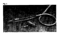
カプセルのアクティベーション、カプセルをアマルガムミキサーに移し、カプセルを練和し、カプセルをアマルガムミキサーから取り出し、カプセルを人力分注デバイスに装填することを含む、従来技術で周知の手順は、手間も時間もかかり、時に、歯科助手の補助を要する。ユーザーがこの処置を実施するために、最大3つの別々の機器を要する場合もある。そこで、本発明は、これら機能のそれぞれを行い、アクティベーション、練和、及び分注用の個別のデバイスにカプセルを移す必要のない使い易いハンドピース及びカプセルシステムに、これら工程をまとめることを意図する。 Conventionally known procedures, including activation of capsules, transfer of capsules to an amalgam mixer, kneading the capsules, removing the capsules from the amalgam mixer, and loading the capsules into a manual dispensing device, are laborious and time consuming. It takes, and sometimes requires the assistance of a dental assistant. The user may require up to three separate devices to perform this procedure. Therefore, the present invention intends to perform each of these functions and combine these steps into an easy-to-use handpiece and capsule system that does not require the transfer of capsules to separate devices for activation, kneading, and dispensing. To do.
本明細書では、セメント及び修復材などの粉末/液体歯科材料を練和及び分注するための昔ながらのアマルガムミキサー及び粉末/液体歯科カプセルに代わるものとして意図される、総じて送達システムとも称する、自動粉末/液体アプリケーター及びカプセル(APLA)についいて記載する。APLA送達システムは、いくつかのデバイス間でカプセルを移すのに手間をかける必要なく同じ結果が得られる、カプセルに入っている材料をアクティベート、練和、及び塗布するために組み合わせて使用される新規のカプセルとハンドピースとからなる。 An automatic, also referred to herein, intended as an alternative to traditional Amalgam mixers and powder / liquid dental capsules for kneading and dispensing powder / liquid dental materials such as cement and restoratives. Described for powder / liquid applicators and capsules (APLA). The APLA delivery system is a novel used in combination to activate, knead, and apply the materials contained in the capsules, with the same results without the hassle of transferring capsules between several devices. Consists of a capsule and a handpiece.
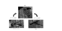
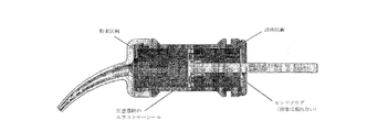
図1の図解は、このようなデバイス及びカプセルの概念図であり、一方、図2のブロック図は、本明細書に記載される機能的態様を概説する。デバイスが、カプセルをアクティベートし練和する(ブロック図 工程3及び工程4)、多数の方法があり、その一部を本明細書に概説する。
The illustration in FIG. 1 is a conceptual diagram of such a device and capsule, while the block diagram in FIG. 2 outlines the functional aspects described herein. There are a number of ways in which the device activates and kneads the capsule (
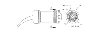
本明細書で開示されるアプリケーターは、3つの主な構成要素:カプセル本体、液体カップ、及びプランジャを有するカプセルを含む。カプセルは、所望の歯科用生成物のために、液体及び粉末成分を予め装填し得る。カプセルは、練和ペーストが送達され、デバイスのリーチを伸ばすための導管の役割を果たす、一体式分注チップも有し得る。一体式チップを使用しない場合、チップをカプセルに取り付ける機構を含むであろう別途の分注チップを使用してもよい。 The applicator disclosed herein includes a capsule having three main components: a capsule body, a liquid cup, and a plunger. Capsules can be preloaded with liquid and powder components for the desired dental product. The capsule may also have an integral dispensing tip to which the kneaded paste is delivered and acts as a conduit for extending the reach of the device. If the integrated tip is not used, a separate dispensing tip that may include a mechanism for attaching the tip to the capsule may be used.
本明細書に開示されるアプリケーターシステムは、ドライブシャフト又はプランジャなどの他の同様の機構、バッテリキャパシタ又は他のそのような電源、カプセルを練和するための機構、ドライブシャフトを徐々に前進させるための機構、カプセルを装填及び抜き出すためのカプセル区画、カプセルを装填及び抜き出す開口、ハンドピースの動作(例えば、アクティベート/練和、塗布など)を制御するコントロールボタン又は同様のオペレータインターフェース制御、チェアサイドデンタルリソースセンターにある歯科用配管などのエネルギー源を含む様々な電気機械的な構成要素を有するハンドピースを含む。 The applicator system disclosed herein includes other similar mechanisms such as drive shafts or plungers, battery capacitors or other such power supplies, mechanisms for kneading capsules, to gradually advance the drive shaft. Mechanism, capsule compartment for loading and unloading capsules, opening for loading and unloading capsules, control buttons to control handpiece movements (eg activation / kneading, application, etc.) or similar operator interface control, chair side dental Includes handpieces with various electromechanical components including energy sources such as dental plumbing in resource centers.
本明細書に開示される1つのコンセプトは、偏心練和チャンバを有するカプセルからなる偏心カプセルである。その上、カプセルは、練和チャンバの軸からずれた主軸でスピンする。本明細書に開示される別のコンセプトは、回転すると同時に偏心軸を周回する練和チャンバからなる遊星練和カプセルである。遊星運動は、専ら、ハンドピースによって、又はカプセルとハンドピースの特徴を組み合わせることを通して、生じることができる。 One concept disclosed herein is an eccentric capsule consisting of a capsule having an eccentric kneading chamber. Moreover, the capsule spins on a spindle off the axis of the kneading chamber. Another concept disclosed herein is a planetary kneading capsule consisting of a kneading chamber that rotates and orbits an eccentric axis at the same time. Planetary motion can occur exclusively by the handpiece or through the combination of capsule and handpiece features.
図1及び図55〜図56に示すように、偏心カプセルは、2つの区画を有し、一方は、粉末を予め充填する練和区画であり、もう一方は、保管及び運搬中に液体を分離するための区画である。本開示において、2つの区画は、主軸からずれており、そのためカプセルが主軸に沿って素早くスピンすると、材料に遠心力がかかり、材料を完全に混合させる。また、ハンドピースの質量が比較的小さく、カプセルが素早く回転するため、ハンドピースは、カプセルの質量ずれにより振動し、このことも練和動作に寄与する。 As shown in FIGS. 1 and 55-5, the eccentric capsule has two compartments, one is a kneading compartment prefilled with powder and the other separates the liquid during storage and transportation. It is a section for doing. In the present disclosure, the two compartments are offset from the spindle so that when the capsule spins quickly along the spindle, centrifugal force is applied to the material and the material is completely mixed. Further, since the mass of the handpiece is relatively small and the capsule rotates quickly, the handpiece vibrates due to the mass shift of the capsule, which also contributes to the kneading operation.
液体区画(カップ)は、液体区画と同軸にあるプランジャを有する。プランジャは、遠位端に、ハンドピースドライブシャフトを受けるための六角穴を有する。六角穴及びドライブシャフトは、回転の主軸に沿って配置される。液体区画及び練和区画の軸は、回転の主軸からずれている(図56)。ドライブシャフトは、六角穴と係合するよう構成される。アクティベーション中、プランジャがドライブシャフトにより前方に押され、液圧力により液体カップにある第1の膜が破裂する。その後、液体は、プランジャが前進することにより、練和チャンバ内へ移動する。プランジャが液体カップの底に達すると、ドライブシャフトが前進を停止し、練和区画への液体の送達が完了する。液体を粉末/練和チャンバに引き入れるこの手順を、アクティベーション(activation)という(図2、工程3)。 The liquid compartment (cup) has a plunger coaxial with the liquid compartment. The plunger has a hex hole at the distal end to receive the handpiece drive shaft. The hex holes and drive shafts are arranged along the main axis of rotation. The axes of the liquid compartment and the kneading compartment are offset from the main axis of rotation (FIG. 56). The drive shaft is configured to engage the hexagonal hole. During activation, the plunger is pushed forward by the drive shaft and the liquid pressure causes the first membrane in the liquid cup to burst. The liquid then moves into the kneading chamber as the plunger advances. When the plunger reaches the bottom of the liquid cup, the drive shaft stops advancing and delivery of the liquid to the kneading compartment is complete. This procedure of drawing the liquid into the powder / kneading chamber is called activation (FIG. 2, step 3).
カプセル本体は、回転の主軸と同心の円形外側フランジを有する。フランジ軸は、回転の主軸と一致し、練和区画の軸からずれている。APLAハンドピースは、カプセルが自由に回転することができる、APLAカプセルを受け入れるために構成される区画を有する(図55)。 The capsule body has a circular outer flange concentric with the main axis of rotation. The flange axis coincides with the main axis of rotation and deviates from the axis of the kneading section. The APLA handpiece has a compartment configured to receive the APLA capsule in which the capsule can rotate freely (Fig. 55).
アクティベーション後、練和が自動で開始され(図2、工程4)、ドライブシャフトは、素早く回転を始動し、カプセルを回転の主軸を中心にスピンさせる。練和区画が回転の主軸からずれているため、粉末及び液体成分には、遠心力がかかり、粉末及び液体成分を混合させる。ハンドピースは、練和されている材料の必要に応じて予め定められた時間、速度、及び方向でカプセルを回転させる。理想的には、このような練和は、約10〜15秒かかるだろう。 After activation, kneading is automatically started (FIG. 2, step 4), the drive shaft quickly starts rotating and spins the capsule around the main axis of rotation. Since the kneading section is deviated from the main axis of rotation, centrifugal force is applied to the powder and liquid components to mix the powder and liquid components. The handpiece rotates the capsule at a predetermined time, speed, and direction as needed for the kneaded material. Ideally, such kneading would take about 10 to 15 seconds.
練和後、まず、分注チップを取り付け(カプセルに内蔵型分注チップが備え付けられていない場合)、その後、コントロールボタン又はフットスイッチを押すことにより、ドライブシャフトが前方に動くことで、ユーザーは、分注を開始する(図2、工程5)。ドライブシャフトが前方へ動くと、練和区画の分注端にある第2の膜が液圧力により破裂する。その後、液体区画及びプランジャ(この時点で、一体で動く)が前方へ進むことにより、ペーストは分注チップの中に移動する。一部の実施形態において、ユーザーは、塗布の最終的な制御を行い、コントロールボタン又はフットスイッチの使用により必要に応じて、ペーストを加減し、分注することができる。 After kneading, the user can first attach the dispensing tip (if the capsule does not have a built-in dispensing tip), and then press the control button or footswitch to move the drive shaft forward. , Start dispensing (Fig. 2, step 5). As the drive shaft moves forward, the liquid pressure causes the second membrane at the dispensing end of the kneading compartment to burst. The paste then moves forward into the dispensing tip as the liquid compartment and plunger (at this point move together) move forward. In some embodiments, the user has final control over the application and can adjust and dispense the paste as needed by using control buttons or footswitches.
ハンドピースは、圧縮空気、電気、水など、通常歯科用椅子のリソースセンターで利用可能なエネルギー源を使用する。おそらく、ハンドピースにある機能ボタンは、以下のように、プログラミングされたシーケンスを開始する。
(1)装填/抜き出し−ハンドピースの区画扉をロックし、ドライブシャフトを前進させて、カプセルプランジャにある六角穴と係合させる(図2、工程1)、及び/又はドライブシャフトを後退させ、使用済みカプセルの取り出しのためにハンドピースの区画扉のロックを解除する(図2、工程6)。
(2)練和−操作者の要求により(図2、工程2)、ドライブシャフトを前進させると、液体が粉末/練和区画の中に移動することにより、カプセルがアクティベートされ、ドライブシャフトが前進を停止し、その後、素早く回転し始め、粉末/液体成分を練和する(図2、工程4)。練和されている材料に特有の練和速度、方向、及び持続時間を制御する予めプログラミングされた練和アルゴリズムを開始する。その後、回転を停止する。
(3)塗布−ユーザーが押したとき、ドライブシャフトが前進して、液体区画/プランジャが前方へ移動してペーストを分注し、解放されたとき、分注を停止する(図2、工程5)。
The handpiece uses energy sources usually available in the resource center of dental chairs, such as compressed air, electricity, and water. Perhaps the function button on the handpiece initiates a programmed sequence as follows:
(1) Loading / Unplugging-Lock the compartment door of the handpiece, advance the drive shaft to engage the hexagonal hole in the capsule plunger (Fig. 2, step 1), and / or retract the drive shaft. Unlock the compartment door of the handpiece to remove the used capsule (Fig. 2, step 6).
(2) Kneading-At the request of the operator (Fig. 2, step 2), when the drive shaft is advanced, the liquid moves into the powder / kneading compartment, activating the capsule and advancing the drive shaft. After that, it starts to rotate quickly to knead the powder / liquid component (Fig. 2, step 4). Initiate a pre-programmed kneading algorithm that controls the kneading rate, direction, and duration specific to the kneaded material. After that, the rotation is stopped.
(3) Coating-When the user pushes, the drive shaft moves forward, the liquid compartment / plunger moves forward to dispense the paste, and when released, the dispensing is stopped (Fig. 2, step 5). ).
一部の実施形態において、本明細書に記載される送達システムでは、図3〜図9及び図11〜図15に描かれるような遊星練和カプセルが使用され得る。 In some embodiments, the delivery system described herein may use planetary kneading capsules as depicted in FIGS. 3-9 and 11-15.
遊星カプセル構成により、惑星が太陽(中心にある主軸)の周りの軌道をたどり、それ自体の軸(偏心軸)で回転する、太陽の周りを周回する惑星と同様の運動が生じる。。自転及び公転の回転の方向は、練和されている個別の生成物の必要性に応じて、別の方向であっても、両者同一の方向であってもよく、また、いずれか一方は前後に揺動することもあるであろう。そのため、様々な練和動作を行うことができる。 The planetary capsule configuration causes a planet to orbit around the sun (the central spindle) and rotate on its own axis (eccentric axis), similar to a planet orbiting the sun. .. The direction of rotation of rotation and revolution may be different or the same, depending on the needs of the individual products being kneaded, and one of them may be in the front-back direction. It may swing to. Therefore, various kneading operations can be performed.
主ドライブシャフト軸は、固定位置軸にあり、カプセルプランジャは、それに従う。主ドライブシャフトがカプセル(遊星)をスピンさせ、補助的なドライブシャフトがハンドピースのカプセルチャンバ(軌道)をスピンさせる。この例において、軌道の径は、遊星の径よりもかなり小さい。 The main drive shaft shaft is on the fixed position shaft and the capsule plunger follows it. The main drive shaft spins the capsule (planet) and the auxiliary drive shaft spins the capsule chamber (orbit) of the handpiece. In this example, the diameter of the orbit is much smaller than the diameter of the planet.
図3で実証されるように、ハンドピースは、カプセルチャンバを回転させることにより、軌道を確立する。練和チャンバと混同されることなく、カプセルチャンバは、カプセルが入っているハンドピース内の区画である。カプセルチャンバは、偏心空洞部を有する。補助的なドライブシャフトは、歯車又は他の同様の接合部分を通し、カプセルチャンバと係合する。この例において、軌道の径は、偏心空洞部のずれの距離の2倍である。 As demonstrated in FIG. 3, the handpiece establishes an orbit by rotating the capsule chamber. Not to be confused with the kneading chamber, the capsule chamber is the compartment within the handpiece that contains the capsule. The capsule chamber has an eccentric cavity. Ancillary drive shafts engage with the capsule chamber through gears or other similar joints. In this example, the diameter of the orbit is twice the distance of the deviation of the eccentric cavity.
主ドライブシャフトは、主軸と完全に一致した軸で回転する。まず、主ドライブシャフトが前進してカプセルプランジャの内面にある偏心歯車接合部分と係合する。その後、主ドライブシャフトは、(指令で)再び前進してカプセルをアクティベートし、液体を粉末/練和チャンバの中に移動させる。アクティベーション中、液体カップ(不図示)にある膜は、プランジャが前進することにより生じる圧力により、破裂する。 The main drive shaft rotates on an axis that exactly matches the main shaft. First, the main drive shaft advances and engages with the eccentric gear joint on the inner surface of the capsule plunger. The main drive shaft then advances again (by command) to activate the capsule and move the liquid into the powder / kneading chamber. During activation, the membrane in the liquid cup (not shown) bursts due to the pressure generated by the advancement of the plunger.
その後、両ドライブシャフトが回転し始めると、練和が自動で始まる。補助的なドライブシャフトにより、偏心軸が主軸の周りを周回し、主ドライブシャフトは、軌道を中心に回転することで、粉末/練和チャンバをスピンさせる。図3〜図9他において、ハンドピースは、明瞭にするため、図示していない。 After that, when both drive shafts start to rotate, kneading starts automatically. The auxiliary drive shaft causes the eccentric shaft to orbit around the spindle, which spins the powder / kneading chamber by rotating about the trajectory. In FIGS. 3-9 and others, the handpiece is not shown for clarity.
図4は、主ドライブシャフトが前進してカプセルプランジャと係合する前の、アクティベーション前の段階にあるカプセル及びハンドピース機構を示す断面である。 FIG. 4 is a cross section showing a capsule and handpiece mechanism in the pre-activation stage before the main drive shaft advances and engages with the capsule plunger.
図5は、ベアリング及びカプセルチャンバを、カプセルの設計に組み込むことができる、又は上記したようなハンドピースの設計の一部として残すことができることを実証する、図7に示すものと同一構成の等尺図である。 FIG. 5 demonstrates that bearings and capsule chambers can be incorporated into the capsule design or left as part of the handpiece design as described above, with the same configuration as shown in FIG. It is a scale.
図6は、かみ合い歯車の接合部分が入っているプランジャポケット内に前進後の主ドライブシャフトを示す。 FIG. 6 shows the main drive shaft after advancing in the plunger pocket containing the joint portion of the meshing gear.
図7は、主ドライブシャフトが前進してプランジャを前方へ押し、その結果、液体コンテナにある膜が破裂して、液体が粉末/練和チャンバの中に移動する、アクティベーション後のアセンブリを示す。アクティベーション後、主ドライブシャフトは、前進を止める。 FIG. 7 shows the post-activation assembly in which the main drive shaft advances and pushes the plunger forward, resulting in the membrane in the liquid container bursting and the liquid moving into the powder / kneading chamber. .. After activation, the main drive shaft stops advancing.
図8は、回転し、遊星運動を生じる両ドライブシャフトを示す。その後、粉末及び液体は、練和運動の結果として、組み合わさり練和ペーストを形成する。 FIG. 8 shows both drive shafts that rotate and produce planetary motion. The powder and liquid are then combined to form a kneading paste as a result of the kneading exercise.
図9は、分注状態にあるアセンブリを示す(ペースト及び分注チップは不図示)。練和後、ドライブシャフトは回転を停止し、再度、指令により主ドライブシャフトは前進して練和ペーストを分注する。練和チャンバの前にある膜が、(液体チャンバに関して前述した同様の手法で)破裂すると、練和チャンバからペーストが放出され、分注チップを通してペーストが送達される(膜及び分注チップは不図示)。 FIG. 9 shows an assembly in a dispensed state (paste and dispense tip not shown). After kneading, the drive shaft stops rotating, and the main drive shaft advances again according to the command to dispense the kneaded paste. When the membrane in front of the kneading chamber bursts (in the same manner as described above for the liquid chamber), the paste is released from the kneading chamber and the paste is delivered through the dispensing tip (the membrane and the dispensing tip are not). Illustrated).
遊星のコンセプトは、練和全体にわたり、同一の箇所にペーストを保つ一定の遠心力という、偏心カプセルのコンセプトにおける固有の課題を解決する。遊星のコンセプトは、軌道中心にも回転しつつ、カプセルを自身の軸を中心に回転させることにより、当該課題を解決する。 The planetary concept solves the unique problem of the eccentric capsule concept of the constant centrifugal force that keeps the paste in the same spot throughout the kneading. The planetary concept solves this problem by rotating the capsule around its own axis while also rotating around the center of the orbit.
図10に示されるように、カプセルのアクティベーション、カプセルをアマルガムミキサーに移し、カプセルを練和し、カプセルをアマルガムミキサーから取り出し、カプセルを人力分注デバイスに装填することを含む、当技術分野で既知の手順は、手間と時間がかかり、歯科助手の補助を要することがある。ユーザーが、この処理を実施するため、最大3つの別々の部品の機器を要する場合もある。そこで、本発明は、それら機能のそれぞれを行い、アクティベーション、練和、及び分注のために個別のデバイスにカプセルを移す必要のない、使い易いハンドピース及びカプセルシステムに、これら工程をまとめることを意図する。 As shown in FIG. 10, in the art, including activating the capsule, transferring the capsule to an amalgam mixer, kneading the capsule, removing the capsule from the amalgam mixer, and loading the capsule into a manual dispensing device. Known procedures are laborious, time consuming, and may require the assistance of a dental assistant. The user may require equipment for up to three separate parts to perform this process. The present invention then combines these steps into an easy-to-use handpiece and capsule system that performs each of these functions and does not require the transfer of capsules to individual devices for activation, kneading, and dispensing. Intended.
偏心カプセルのコンセプトの1つの望ましい特徴は、練和区画の軸が、回転軸からずれていることである。カプセルが、回転軸を中心に素早く回ると、遠心力により、液体及び粉末の成分が共に練和される。また、カプセルに対し、ハンドピースの質量が比較的小さいため、ハンドピースは、カプセルのオフセット質量により振動するであろう。この振動は、構成要素にさらに別の重要な練和動作を加える。別の望ましい特徴は、カプセル及びハンドピースが、同時に作用する場合に限って全体としてのシステムの利点が得られる歯科材料アプリケーションシステムの一部であり得ることである。他の競合するカプセルは、偏心性の練和又は遊星運動による練和を有さず、代替ハンドピースの作用機構に適合するよう構成されないため、ハンドピースは、他の競合するカプセルと共に使用することができない。 One desirable feature of the eccentric capsule concept is that the axis of the kneading section deviates from the axis of rotation. As the capsule rotates quickly around the axis of rotation, centrifugal force kneads the liquid and powder components together. Also, because the mass of the handpiece is relatively small relative to the capsule, the handpiece will vibrate due to the offset mass of the capsule. This vibration adds yet another important kneading action to the components. Another desirable feature is that the capsule and handpiece can be part of a dental material application system that provides the benefits of the system as a whole only if they act simultaneously. Handpieces should be used with other competing capsules, as other competing capsules do not have eccentric or planetary kneading and are not configured to fit the mechanism of action of the alternative handpiece. I can't.
また別の望ましい特徴は、本明細書に記載されるカプセルが、昔ながらのアマルガムミキサー及びカプセルディスペンサーと連携し得るがが、(上記にて説明したように)他のカプセルは、本明細書に開示されるハンドピースで作用することはできないことである。ハンドピースが故障した場合に、大抵の歯科医院はアマルガムミキサーを有しており、ユーザーがバックアップシステムとしてアマルガムミキサーを使用することができるため、これは優れた利点である。ユーザーが本明細書に開示されるハンドピースの購入を望まない場合、ユーザーは、所有する機器を用いてカプセルを使用することができ、競合するカプセルとも全く同様に作用するであろう。そこで、本明細書に開示される出願人のアプリケーターシステムは、システム全体を使用することを望む者に競争上の優位性を提供し、それを望まない者にも不利益を与えない。 Yet another desirable feature is that the capsules described herein can work with traditional amalgam mixers and capsule dispensers, while other capsules (as described above) are disclosed herein. It is not possible to work with a handpiece that is made. This is an excellent advantage as most dental clinics have an amalgam mixer in the event of a handpiece failure, allowing the user to use the amalgam mixer as a backup system. If the user does not wish to purchase the handpieces disclosed herein, the user may use the capsule with his or her own equipment and will work in exactly the same way as competing capsules. Therefore, the applicant's applicator system disclosed herein provides a competitive advantage to those who desire to use the entire system and does not disadvantage those who do not.
また別の望ましい特徴は、電動分注能である。これまで、セメントカプセル由来のペーストは、通常、ハンドルと、プランジャに作用するレバーとからなる手動分注ガンにより送達されていた。当該分注ガンは、プランジャを押す必要がある機械的優位性を提供するが、それでもなお、ペースト塗布を制御すると同時に力を提供することを操作者に依存する。出願人の新規のハンドピース及びカプセルは、ハンドピース内にある(又は、チェアサイドリソースセンターにより供給される)エネルギー源により作動する。操作者は、単に、制御ボタンを押し、ドライブシャフトを前進させ、生成物を分注する。この操作は、操作者が送達力を同時に提供、制御、モニタリングする必要がないため、操作者が必要とされる感覚的制御がより少ない。また別の利点は、本明細書に記載されるハンドピースが、図10に示す手動式カプセルアプリケーターよりもより人間工学に基づいたペン形状であり得ることである。 Another desirable feature is the electric dispensing capacity. Previously, cement capsule-derived pastes were typically delivered by a manual dispensing gun consisting of a handle and a lever acting on the plunger. The dispensing gun provides the mechanical advantage of having to push the plunger, but still relies on the operator to control the paste application and at the same time provide the force. Applicant's new handpieces and capsules are powered by energy sources within the handpiece (or supplied by the chairside resource center). The operator simply presses the control button to advance the drive shaft and dispense the product. This operation requires less sensory control by the operator because the operator does not need to simultaneously provide, control, and monitor the delivery force. Yet another advantage is that the handpieces described herein can have a more ergonomic pen shape than the manual capsule applicator shown in FIG.
また別の望ましい特徴は、本明細書に記述のシステムが、アクティベーション、及び分注の機能を1つのデバイスに兼ね備えていることである。以前は、それら機能は、同じ目標を達成するため、別々のデバイスを使用して、デバイス間でカプセルを移すことを要した。本発明により、ユーザーにとって修復処置の複雑さが大いに簡略化され、開業医が、患者及び処置により集中し、修復材の調合の調整にあまり集中せずにすみ、結果として、より良い患者の医療を得ることができる。 Yet another desirable feature is that the system described herein combines activation and dispensing functionality in a single device. Previously, those features required the use of separate devices to transfer capsules between devices in order to achieve the same goal. The present invention greatly simplifies the complexity of the repair procedure for the user, allowing the practitioner to focus more on the patient and treatment and less on adjusting the formulation of the repair material, resulting in better patient care. Obtainable.
本明細書に開示される遊星カプセルのまた別の望ましい特徴は、練和チャンバの壁が連続して回転し、新たな位置になり、ペーストが遠心力により外側に留まりがちになるため、遊星運動が、連続した鋭く回転する運動を提供することである。 Another desirable feature of the planetary capsules disclosed herein is the planetary motion as the walls of the kneading chamber rotate continuously to reposition and the paste tends to stay outward due to centrifugal force. Is to provide a continuous, sharply rotating motion.
さらに、本明細書に開示されるアプリケーターシステムは、一方向のみのスピンに加え、様々な練和運動を使用することを目的とする。ハンドピースは、方向を反転させ、前後に回転する運動に対して反対方向にスピンするようプログラムすることができよう。そうすることにより、構成要素は、ペーストの慣性によって純粋な力を受けて、方向を素早く変化させる。遊星カプセルの場合、一方のみからの回転、同じ方向の回転、互いに異なる速度の回転、及び互いに逆方向の回転を含む、2つのドライブシャフトからの回転の任意の組み合わせを使用することが可能である。 Further, the applicator system disclosed herein is intended to use a variety of kneading movements in addition to spin in only one direction. The handpiece could be programmed to reverse direction and spin in the opposite direction to a back-and-forth rotating motion. By doing so, the components are subjected to pure force by the inertia of the paste to quickly change direction. For planetary capsules, it is possible to use any combination of rotations from two drive shafts, including rotations from only one side, rotations in the same direction, rotations at different velocities, and rotations in opposite directions. ..
本明細書に開示されるアプリケーターシステムは、カプセルが、その特定の生成物のために使用される練和プログラムを識別する、ハンドピースに入れられたリーダーにより復号することができる、RFID(無線周波数識別(radio frequency identification))ラベルを有する、「スマート」なパッケージの通信システムを含み得る。 The applicator system disclosed herein can be decoded by a reader placed in a handpiece, where the capsule identifies the kneading program used for that particular product, RFID (radio frequency identification). It may include a "smart" packaged communication system with a radio frequency identification label.
本明細書に開示されるアプリケーターシステムは、ハンドピース内にあり、練和ペーストにおける空隙率を低下させるため、カプセルの内部を真空にする、バキュームを含み得る。バキュームは、歯科用椅子のチェアサイドリソースセンターで利用可能なエネルギーにより作動し得る。本明細書に開示されるアプリケーターシステムは、ドライブシャフトにより加えられる突発的なトルクによりカプセルアセンブリが摺動することを防ぐため、液体区画/及び又はプランジャ及び/又はカプセル本体にリブ、溝、又は他の同様な係合機構を組み込み得る。 The applicator system disclosed herein may include a vacuum that evacuates the inside of the capsule to reduce the porosity in the kneading paste, which is in the handpiece. The vacuum can be activated by the energy available at the chairside resource center of the dental chair. The applicator systems disclosed herein include ribs, grooves, or the like in the liquid compartment / and / or plunger and / or capsule body to prevent the capsule assembly from sliding due to sudden torque applied by the drive shaft. A similar engagement mechanism can be incorporated.
本明細書に開示されるアプリケーターシステムは、修復部位にペーストを直接送達するための、内蔵型分注チップ又は追加(アフターマーケット)分注チップを含み得る。 The applicator system disclosed herein may include a built-in dispensing tip or an additional (aftermarket) dispensing tip for delivering the paste directly to the repair site.
本明細書に開示されるアプリケーターシステムは、障害物を越えて材料の向きを変えることにより練和動作を促進する、練和区画にある内部リブを含み得る。そのようなリブは、回転の軸に平行である、垂直にある、又はらせん状とすることができよう。 The applicator system disclosed herein may include internal ribs in the kneading compartment that facilitate the kneading operation by turning the material over obstacles. Such ribs could be parallel, perpendicular, or spiral to the axis of rotation.
本明細書に開示されるアプリケーターシステムは、一体成型された薄壁部分、熱融着ポリ/箔ラミネートなどの材料製の液体区画及び練和区画にある脆い膜を含み得る。この成形されたプラスティック膜は、制御された手法で、破砕区域を誘導する脆い通路を有し、厚い領域は、脆い膜の部分が意図せず、離脱してペーストに組み込まれるようになることを防ぎ得る。このように、厚みのある部分は、ヒンジの役割を果たす。 The applicator system disclosed herein can include brittle membranes in integrally molded thin wall portions, liquid compartments and kneading compartments made of materials such as heat-sealed poly / foil laminates. This molded plastic membrane, in a controlled manner, has brittle passages that guide the crushed area, and thick areas allow brittle membrane portions to unintentionally detach and be incorporated into the paste. Can be prevented. Thus, the thick portion acts as a hinge.
工程の終了又はハンドピースの準備完了状態を合図するため、可聴音、メッセージ、又はLED信号光の使用は、本明細書に開示されるアプリケーターシステムに含まれ得る。例えば、生成物を練和した後、材料は、操作者がそれを分注しなければならない特有の作業時間を有するであろう。ハンドピースは、使用される材料に特有で、ユーザーを材料の分注及び塗布へと誘導する、光、可聴音、事前記録メッセージなどを用いて、ユーザーに合図することができよう。例えば、作用時間の減りを示すゲージ、「分注準備完了」と言う事前記録音声プロンプト、異なる段階でビープ音が鳴る可聴音など。 The use of audible sounds, messages, or LED signal lights to signal the end of the process or the ready state of the handpiece may be included in the applicator system disclosed herein. For example, after kneading the product, the material will have a unique working time that the operator must dispense it. The handpiece will be specific to the material used and will be able to signal the user with light, audible sounds, pre-recorded messages, etc. that guide the user to the dispensing and application of the material. For example, a gauge that indicates a reduction in duration of action, a pre-recorded voice prompt that says "ready to dispense," or an audible beep at different stages.
本明細書に開示されるアプリケーターシステムは、特有の機能のアップデートをダウンロードするため、又はインターネット上での自己診断を行うため、或いは、ソフトウェアプログラムをアップデートするため、ハンドピースにあるUSBコンピュータ接続を含み得る。 The applicator system disclosed herein includes a USB computer connection on the handpiece to download specific feature updates, to perform self-diagnosis on the Internet, or to update software programs. obtain.
本明細書に開示されるアプリケーターシステムは、ペーストが送達されているが、ユーザーが分注の停止を望み、塗布ボタンの押下を停止するとき、ドライブシャフトが、圧力を抜き、ペーストが分注チップの外に漏出することを防ぐのに十分少量後退する、予めプログラミングされた圧力放出形体を含み得る。 In the applicator system disclosed herein, the paste is delivered, but when the user wants to stop dispensing and stops pressing the apply button, the drive shaft releases pressure and the paste is the dispensing tip. It may include a pre-programmed pressure release form that recedes a small amount enough to prevent it from leaking out of the paste.
本明細書に開示されるアプリケーターシステムは、アクティベーション及び分注中、デバイスがカプセルを過加圧することを防ぐ、モーター電流限界検出などの圧力検知制限能を含み得る。 The applicator system disclosed herein may include pressure sensing limiting capabilities such as motor current limit sensing that prevent the device from overpressurizing the capsule during activation and dispensing.
本明細書に開示されるアプリケーターシステムは、(上記にて説明したように)特有の装填ボタンを要しない自動装填機能を含み得る。この目的において、カプセルが装填されてアクセス扉が閉じた時間をハンドピースが検知し、ドライブシャフトを自動で前進させ、カプセルプランジャにある六角穴と係合する。このように、プランジャ及び駆動機構は、予め配置され、指令によりアクティベーションされる準備ができているであろう。 The applicator system disclosed herein may include an autoloading function that does not require a specific loading button (as described above). For this purpose, the handpiece detects when the capsule is loaded and the access door is closed, automatically advancing the drive shaft and engaging with the hexagonal hole in the capsule plunger. As such, the plunger and drive mechanism will be pre-arranged and ready to be activated by command.
本明細書に開示されるアプリケーターシステムは、材料が分注されてドライブシャフトがこれ以上前進することができなくなった後、ドライブシャフトが後退してハンドピース区画扉のロックを自動で解除し、それによって空のカプセルが取り出され得るという、自動抜き出し機能を含み得る。 The applicator system disclosed herein automatically retracts the drive shaft to unlock the handpiece compartment door after the material has been dispensed and the drive shaft cannot move forward any further. It may include an automatic extraction function that allows empty capsules to be removed.
本明細書に開示されるアプリケーターシステムは、そのようにするための液圧力の必要性を排除するため、(練和後)塗布されるとき、練和区画にある第2膜を突き刺す分注チップを活用することができる。 The applicator system disclosed herein eliminates the need for hydraulic pressure to do so, and when applied (after kneading), a dispensing tip that pierces a second membrane in the kneading compartment. Can be utilized.
本明細書に開示されるアプリケーターシステムは、攪拌を高めるために回転運動に加えて軸方向の振動運動を加える、ハンドピースカプセル区画の端面、又はカプセルの遠位端、及び/又はその両方にあるカムを利用することができる。そのため、ドライブシャフトは、ばねで装填され、カムの進路に従うよう機構を誘導しなければならないであろう。 The applicator system disclosed herein is on the end face of the handpiece capsule compartment, or the distal end of the capsule, and / or both, which applies axial vibrational motion in addition to rotational motion to enhance agitation. You can use the cam. Therefore, the drive shaft will have to be spring loaded and guide the mechanism to follow the path of the cam.
本明細書に開示されるアプリケーターシステムは、成分の練和を容易にする又はさらに増進させるため、圧電トランスデューサーにより発生する振動などの、音波振動又は超音波振動を利用することができる。本発明内で利用することができ、粉末/液体成分のペーストへの練和を容易にする他の技術があることに留意すべきである。 The applicator system disclosed herein can utilize sonic or ultrasonic vibrations, such as vibrations generated by piezoelectric transducers, to facilitate or further enhance the kneading of the components. It should be noted that there are other techniques that can be utilized within the present invention that facilitate the kneading of powder / liquid components into the paste.
偏心のコンセプトに関し、本開示は、さらに、前述の六角ドライブの代わりに、遊星歯車を利用してカプセルをスピンさせることをさらに目的とする。ハンドピースは、歯車の歯が、カップの内側にある被動歯車装置と係合した状態で、回転の軸に固定されたドライブシャフトを有するであろう。この構成は、先に記載した六角ドライブ連結機構を用いるなどの特有の手法で、カップの方向を決める必要がないため、有益であろう。ドライブシャフト歯車の前縁にある面取り部は、被動歯車にある同様の面取り部と係合し、ドライブシャフトが、まず、装填段階の間より前に、液体カップに入ると、カプセルの方向を決定するであろう。 With respect to the concept of eccentricity, the present disclosure further aims to spin the capsule using planetary gears instead of the hexagonal drive described above. The handpiece will have a drive shaft fixed to the axis of rotation, with the gear teeth engaged with the driven gear device inside the cup. This configuration would be beneficial because it does not require the direction of the cup to be determined by a unique technique such as using the hexagonal drive coupling mechanism described above. The chamfer on the front edge of the drive shaft gear engages with a similar chamfer on the driven gear to determine the orientation of the capsule when the drive shaft first enters the liquid cup before during the loading phase. Will do.
遊星練和
図面の簡単な説明
A brief description of the planetary training drawings
図11は、遊星練和運動を生じるための粉末/液体カプセルを例証する。 FIG. 11 illustrates a powder / liquid capsule for producing a planetary kneading motion.
図12は、図11のカプセルの分解組立図を例証する。 FIG. 12 illustrates an exploded view of the capsule of FIG.
図13は、図11のカプセルの断面を例証する。 FIG. 13 illustrates the cross section of the capsule of FIG.
図14は、ディスペンサーの六角ドライブ及びリングギヤと係合するカプセルを例証する。 FIG. 14 illustrates a capsule that engages a hexagonal drive and ring gear of a dispenser.
図15は、プランジャドライバ及び支柱の偏心軸の側面図及び端面図を例証する。 FIG. 15 illustrates a side view and an end view of the eccentric shaft of the plunger driver and the column.
符号の説明
10 カプセル
11 本体
12 ノズル
13 液体カップ
14 プランジャ
15 プランジャドライバ
16 遊星歯車
17 六角ドライブ穴
18 プランジャドライバ支柱
21 リングギヤ
22 六角駆動シャフト
30 回転の主軸
31 プランジャドライバ支柱及びカプセル本体のオフセット軸
Description of the
物性、特性、独自の革新的な特徴
図11〜図15の画像では、カプセルとインターフェースで接続するリングギヤ及び六角ドライブを除き、ディスペンサーは記載していない。図11〜図15の遊星カプセルは、以下に記載される図3〜図9の遊星システムの代替実施形態である。
Physical characteristics, characteristics, and unique and innovative features In the images of FIGS. 11 to 15, the dispenser is not described except for the ring gear and the hexagonal drive that are connected to the capsule by an interface. The planetary capsules of FIGS. 11 to 15 are alternative embodiments of the planetary system of FIGS. 3 to 9 described below.
カプセルにある歯車装置は、ディスペンサーにある歯車装置とインターフェースで接続され、所望の遊星運動を生じる。練和は、動作中の機構の遠心力及び残留振動により成し遂げられる。ディスペンサーのリングギヤは、静止している。カプセル本体の遊星歯車は、ディスペンサーのリングギヤと噛合する平歯車である。 The gearing device in the capsule is interfaced with the gearing device in the dispenser to produce the desired planetary motion. Kneading is achieved by the centrifugal force and residual vibration of the operating mechanism. The ring gear of the dispenser is stationary. The planetary gear of the capsule body is a spur gear that meshes with the ring gear of the dispenser.
カプセルは、本体と、ノズルと、液体カップと、プランジャと、プランジャドライバとからなる。粉末は、練和区画と称する、本体の遠位端部分に入っている。練和区画は、脆い膜によってノズルから隔てられている。液体カップは、カプセルの近位端を封止して、それにより練和区画に粉末を含む。液体は、遠位端に脆い膜を有する液体カップに入っている。液体カップの近位端は、摩擦嵌合プランジャにより封止される。プランジャの近位端は、プランジャドライバの遠位端にある支柱とかみ合う円筒穴を有する。ドライバ支柱は、プランジャの円筒穴と緩嵌し、そのため、自由に回転することができる。プランジャドライバの近位端は、ディスペンサーの六角形状シャフトとかみ合うように構成される六角形状穴を有するフランジを有する。六角形状穴の軸と、プランジャドライバ支柱の軸とは、ずれており、平行である。六角形状穴の軸は、回転の主軸及びディスペンサーのリングギヤの軸と一致する。ドライバ支柱の軸は、カプセル本体、液体カップ、及びプランジャの軸と一致する。 The capsule consists of a main body, a nozzle, a liquid cup, a plunger, and a plunger driver. The powder is contained in a distal end portion of the body, called the kneading compartment. The kneading compartment is separated from the nozzle by a brittle membrane. The liquid cup seals the proximal end of the capsule, thereby containing the powder in the kneading compartment. The liquid is contained in a liquid cup with a brittle membrane at the distal end. The proximal end of the liquid cup is sealed by a friction fitting plunger. The proximal end of the plunger has a cylindrical hole that meshes with a strut at the distal end of the plunger driver. The driver stanchion fits loosely into the cylindrical hole in the plunger, so it can rotate freely. The proximal end of the plunger driver has a flange with a hexagonal hole configured to mesh with the hexagonal shaft of the dispenser. The axis of the hexagonal hole and the axis of the plunger driver strut are offset and parallel. The axis of the hexagonal hole coincides with the axis of rotation and the axis of the ring gear of the dispenser. The axis of the driver post coincides with the axis of the capsule body, liquid cup, and plunger.
ディスペンサーの六角軸は、プランジャドライバの六角形状穴と係合する。プランジャドライバの偏心軸により、カプセル本体の遊星歯車が、ディスペンサーのリングギヤと係合する。六角シャフトが回ると、プランジャドライバ支柱が主軸の周りを周回し、それにより、遊星歯車がリングギヤの周りを周回する。結果として生じる運動により、カプセル本体は、リングギヤの周りを周回すると同時に自転する。 The hexagonal shaft of the dispenser engages the hexagonal hole of the plunger driver. The eccentric shaft of the plunger driver engages the planetary gear of the capsule body with the ring gear of the dispenser. As the hex shaft rotates, the plunger driver struts orbit around the spindle, causing the planetary gears to orbit around the ring gear. Due to the resulting movement, the capsule body orbits around the ring gear and at the same time rotates on its axis.
歯車の歯は、互いに噛合し、干渉することなく、自由に回転するよう配置される。遊星歯車は、リングギヤより歯が少ない。例えば、リングギヤの歯に対する遊星歯車の歯の比率は、55:60である。六角ドライブが、時計回りに回転すると、本体において、ギヤ比に関し、反時計回りの回転が生じる。 The teeth of the gears are arranged so that they mesh with each other and rotate freely without interfering with each other. Planetary gears have fewer teeth than ring gears. For example, the ratio of planetary gear teeth to ring gear teeth is 55:60. When the hexagonal drive rotates clockwise, a counterclockwise rotation occurs in the main body with respect to the gear ratio.
カプセルは、プランジャを押して液体カップ内に前進させるように、ディスペンサーの六角ドライブシャフトを前進させることによりアクティベートされる。液圧によって液体カップの膜が破裂して、液体が練和区画に放出される。アクティベーション後、六角ドライブシャフトは、前進を停止し、練和工程を行うことができる。六角ドライブが回転し始めると、上記にて説明したように、カプセルは、リングギヤの周りに駆動される。 The capsule is activated by advancing the hexagonal drive shaft of the dispenser as it pushes the plunger forward into the liquid cup. The hydraulic pressure causes the membrane of the liquid cup to burst and the liquid is discharged into the kneading compartment. After activation, the hexagonal drive shaft can stop advancing and perform the kneading process. When the hex drive begins to rotate, the capsule is driven around the ring gear, as described above.
回転は、非常に速く、粉末及び液体成分を練和させることが好ましい。遠心力によって、粉末及び液体が練和区画の内壁に向けて分散される。偏心回転により、カプセル本体の内側の壁が回転し、ペーストが最外方位に向かって側壁の上を連続的に流れる。この手法において、ペーストは、連続して向きを変えて練和している。 The rotation is very fast and it is preferable to knead the powder and liquid components. Centrifugal force disperses the powder and liquid towards the inner wall of the kneading compartment. The eccentric rotation causes the inner wall of the capsule body to rotate and the paste to flow continuously over the side walls towards the outermost direction. In this method, the paste is continuously turned and kneaded.
練和ブレード
物性、特性、独自の革新的な特徴
Kneading blade Physical characteristics, characteristics, unique and innovative features
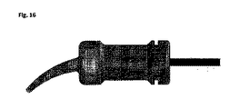
図16は、充填段階/アクティベーション待ち段階にあるカプセルの側面図を例証する。 FIG. 16 illustrates a side view of a capsule in the filling / waiting for activation stage.
図17は、カプセルの構成要素の分解組立図を示す。 FIG. 17 shows an exploded view of the components of the capsule.
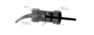
図18は、充填段階/アクティベーション待ち段階にあるカプセルの等尺断面図である。カプセルは、歯科修復材の粉末成分及び液体成分が充填される(粉末及び液体は不図示)。 FIG. 18 is an isometric cross-sectional view of the capsule in the filling stage / waiting stage for activation. The capsule is filled with the powder component and the liquid component of the dental restoration material (powder and liquid are not shown).
図19は、ドライブシャフトを係合し、引き戻してカプセルをアクティベートする六角ドライブを有するハンドピースに装填されるときのカプセルの断面を示す。液体区画にある流体は、通路を通り、粉末保管/練和区画に流れる。 FIG. 19 shows a cross section of a capsule when loaded into a handpiece with a hex drive that engages and pulls back the drive shaft to activate the capsule. The fluid in the liquid compartment flows through the aisle to the powder storage / kneading compartment.
図20は、完全に後退して液封を保持溝内に移動させた後のドライブシャフトのクローズアップ断面図である。 FIG. 20 is a close-up cross-sectional view of the drive shaft after it is completely retracted and the liquid seal is moved into the holding groove.
図21は、六角ドライブが、時計周りに回転して1次及び2次ディスクにある穴の位置を合わせ、ドライブシャフトが、練和チャンバで往復運動してペーストが練和される、アクティベートされたカプセルを練和する図案である。 In FIG. 21, the hexagonal drive is rotated clockwise to align the holes in the primary and secondary discs, and the drive shaft reciprocates in the kneading chamber to knead the paste. It is a design to knead the capsule.
図22aは、1次ディスクを時計回りに回転させることにより、どのように穴の位置を合わせるかを例証する断端面図である。 FIG. 22a is a stump view illustrating how the holes are aligned by rotating the primary disk clockwise.
図22bは、1次ディスクを反時計回りに回転させることにより、どのように穴を閉じる(位置をずらす)かを例証する断端面図である。 FIG. 22b is a stump view illustrating how the holes are closed (shifted in position) by rotating the primary disc counterclockwise.
図23は、練和ペーストを押し出す準備中のカートリッジを示す。ドライブシャフトは、近位端に配置され、反時計回りに回転して穴を閉じる。その後、ドライブシャフトは、ディスクを前進させ、ディスクは練和ペーストを移動させるためのピストンの役割を果たすことができる。 FIG. 23 shows a cartridge in preparation for extruding the kneaded paste. The drive shaft is located at the proximal end and rotates counterclockwise to close the hole. The drive shaft then advances the disc, which can act as a piston for moving the kneading paste.
図24は、完全に押し出されたカプセルの断面を示す。 FIG. 24 shows a cross section of a fully extruded capsule.
図25は、共に又は独立して使用することができる、ドーナツ形状の液体カップ及び可撓性の折り畳み式練和ブレードといった、2つの代替実施形態を示す。 FIG. 25 shows two alternative embodiments, a donut-shaped liquid cup and a flexible foldable kneading blade, which can be used together or independently.
図26は、膜が破裂して、練和ブレードが往復運動してペーストが練和される、アクティベートされた段階にあるドーナツ形状の液体カップを例証する。 FIG. 26 illustrates a donut-shaped liquid cup in the activated stage where the membrane ruptures and the kneading blade reciprocates to knead the paste.
図27は、ペーストが完全に分注された空のカプセルを示す。ペーストは、液体カップ及びプラグを一体で前進させることにより、分注される。可撓性練和ブレードは、圧縮下で折り畳まれる。 FIG. 27 shows an empty capsule in which the paste has been completely dispensed. The paste is dispensed by advancing the liquid cup and plug together. The flexible kneading blade is folded under compression.
図28は、折り畳まれたブレードの端面図を示す。各ブレードの周囲には、アセンブリ全体が折り畳まれると、その中にペーストを絞り出すことができる小さな空間がある。 FIG. 28 shows an end view of the folded blade. Around each blade is a small space in which the paste can be squeezed out when the entire assembly is folded.
図29は、アクティベートされるまで、1次及び2次ディスクが液体及び粉末をそれらの各区画に効果的に封止する代替実施形態を例証する。 FIG. 29 illustrates an alternative embodiment in which the primary and secondary discs effectively seal liquids and powders in their respective compartments until activated.
図17から図24を参照して、カプセルの構成要素を以下により詳細に記載する。 The components of the capsule are described in more detail below with reference to FIGS. 17-24.
製剤の粉末成分は、カプセルの遠位に保管される。一対の穴あき練和ディスクが、粉末保管区画に入っている。1つは、回転手段であるドライブシャフトにしっかり固定される一次ディスクである。もう1つは、ドライブシャフトに緩く固定される2次ディスクである。2次ディスクは、1次ディスクが回転するとき、2次ディスクが回転に抵抗し、それにより、一方のディスクの、もう一方に対する位置に影響を与えるよう、練和チャンバの内側の壁とのわずかな摩擦嵌合を有する。 The powder component of the formulation is stored distal to the capsule. A pair of perforated kneading discs are contained in the powder storage compartment. One is a primary disk that is firmly fixed to a drive shaft that is a means of rotation. The other is a secondary disc that is loosely fixed to the drive shaft. The secondary disc is slightly relative to the inner wall of the kneading chamber so that when the primary disc rotates, the secondary disc resists rotation, thereby affecting the position of one disc with respect to the other. Has a good frictional fit.
2次ディスクは、外縁に沿って、1次ディスクに付随する停止ブロックとかみ合う溝を有する。溝及び停止ブロックは、1次ディスクが回転するとき、必要に応じて、穴の位置を合わせる又は穴の位置をずらすよう構成される。位置合わせは、練和のために使用され、1次ディスクの時計回りの回転を用いて成し遂げられる。位置ずらしは、ドライブシャフトを反時計回りに回すことにより生じ、穴を閉じるために使用され、ピストンのようにペーストを押し出すために使用される。 The secondary disc has a groove along the outer edge that meshes with the stop block associated with the primary disc. Grooves and stop blocks are configured to align or shift the holes as needed as the primary disc rotates. Alignment is used for kneading and is accomplished using the clockwise rotation of the primary disc. The misalignment is caused by turning the drive shaft counterclockwise and is used to close the hole and to push out the paste like a piston.
液封ディスクは、粉末保管区画と液体保管区画との間の液体の密封を形成する。液封ディスクの最外面は、カプセル本体の内径との液体の密封を生じ、粉末保管区画への前進を防ぐよう小さなレッジに接触して配置される。液封ディスクは、液体を密封すると共に、中央に、カプセルの近位端に向けてドライブシャフトがその中を伸長する穴をも有する。 The liquid-sealed disc forms a liquid seal between the powder storage compartment and the liquid storage compartment. The outermost surface of the liquid-sealed disc is placed in contact with a small ledge to provide a liquid seal with the inner diameter of the capsule body and prevent advancing into the powder storage compartment. The liquid-sealed disc seals the liquid and also has a central hole in which the drive shaft extends into it towards the proximal end of the capsule.
液体保管領域は、カプセル本体の近位端まで密封されるエンドキャップにより完成する。エンドキャップは、液体を密閉すると共に、ドライブシャフト用に、中心に穴を有する。 The liquid storage area is completed by an end cap that is sealed to the proximal end of the capsule body. The end cap seals the liquid and has a central hole for the drive shaft.
液体保管領域の内壁は、カプセル本体の主軸に平行に走り、液封が存在するレッジからわずかに近位に配置される、液体チャンバの外側の壁に沿った少なくとも1つの溝を有する。カプセルは、ドライブシャフトで引き戻し、液封ディスクを離脱させることにより、アクティベートされる。液封ディスクが溝の遠位開始点を通過するとき、液体は、粉末保管チャンバに移動する。ドライブシャフトが最後まで引き戻されるとき、液封ディスクのシールフランジは、外側にはね返り、カプセル本体の近位端近くの保持溝に捕らえられ、これ以上シールディスクが軸方向に移動することを防ぐ。 The inner wall of the liquid storage area has at least one groove along the outer wall of the liquid chamber that runs parallel to the main axis of the capsule body and is located slightly proximal to the ledge where the liquid seal resides. The capsule is activated by pulling it back on the drive shaft and removing the liquid-sealed disc. As the liquid sealing disc passes the distal starting point of the groove, the liquid moves to the powder storage chamber. When the drive shaft is pulled back to the end, the seal flange of the liquid-sealed disc bounces outward and is trapped in the retaining groove near the proximal end of the capsule body, preventing further axial movement of the seal disc.
その後、ドライブシャフトは、時計回りに回り、穴を開ける。同時に、ドライブシャフトは、近位の場所から遠位の場所まで、ペーストを練和するのに必要な回数、往復運動する。粉末/液体混合物は、回転ディスクにある穴を通過し、ペーストに練和される。回転の速度、往復運動サイクルの数、及び練和時間は、可変であり、特有のペースト製剤の必要性に応じて調整される。 The drive shaft then turns clockwise to make a hole. At the same time, the drive shaft reciprocates from the proximal location to the distal location as many times as necessary to knead the paste. The powder / liquid mixture passes through a hole in the rotating disk and is kneaded into the paste. The speed of rotation, the number of reciprocating cycles, and the kneading time are variable and are adjusted according to the needs of the specific paste formulation.
ペーストが十分に練和されると、ドライブシャフトは、近位の場所へ最後まで引き戻され、反時計回りに回り、穴を閉じる。その後、ドライブシャフトは、閉じたディスクをピストンとして使用して前方に移動し、ノズルを通してペーストを分注する。 When the paste is well kneaded, the drive shaft is pulled back to its proximal location, turning counterclockwise and closing the holes. The drive shaft then uses the closed disc as a piston to move forward and dispense the paste through the nozzle.
付加的実施形態
一実施形態は、図29に示されるように、液体区画と粉末区画とを隔てるため、1次及び2次ディスクを使用する。ディスクは、練和穴が閉位置にあるとき、それらの間で液体の密封を生じるであろう。液体の密封は、2次ディスクと、ドライブシャフトとの間、及び2次ディスクとカプセル本体の内側の壁との間にも形成されるであろう。エストラマーシールは、閉位置にある各穴において、効果的な液体の密封を形成するために利用することができよう。あるいは、エストラマーディスクは、必要とする液体の密封を形成するため、1次及び2次ディスクの間で利用することができよう。
Additional Embodiments One embodiment uses primary and secondary discs to separate the liquid compartment from the powder compartment, as shown in FIG. The disc will result in a liquid seal between the kneading holes when they are in the closed position. A liquid seal will also be formed between the secondary disc and the drive shaft, and between the secondary disc and the inner wall of the capsule body. Elastomer seals could be used to form an effective liquid seal at each hole in the closed position. Alternatively, the elastomeric disc may be utilized between the primary and secondary discs to form a seal of the required liquid.
付加的実施形態は、図25に示すように、ドーナツ形状の液体カップからなる。カップは、カプセル本体の内面とプラグシールを形成することができるよう、低密度ポリエチレン(LDPE)又はポリプロピレン(PP)などの軟質プラスティックからなる。遠位端には、隣接した薄い部分又は熱融着箔部材のいずれかとして形成される脆いシールを有するであろう。 An additional embodiment consists of a donut-shaped liquid cup, as shown in FIG. The cup is made of a soft plastic such as low density polyethylene (LDPE) or polypropylene (PP) so that it can form a plug seal with the inner surface of the capsule body. At the distal end, there will be a brittle seal formed as either an adjacent thin portion or a heat-sealed foil member.
別の実施形態は、2つ以上のブレードを有するプロペラによく似た練和ブレードからなる。ブレードは、回転運動及び往復運動を提供するシャフトの端に支持される。ブレードの外縁は、シャフトにさらに接続される放射状部材に取り付けられる外輪により支持され得る。ブレードは、その製造時に使用されるプラスティックの可撓性のある特質により、分注中、邪魔にならないように、折り畳むことができよう。 Another embodiment consists of a kneading blade that closely resembles a propeller with two or more blades. The blades are supported at the ends of the shaft that provide rotational and reciprocating motion. The outer edge of the blade may be supported by an outer ring attached to a radial member further connected to the shaft. Due to the flexible nature of the plastic used in its manufacture, the blades could be folded out of the way during dispensing.
物性、特性、独自の革新的な特徴
図30〜図41は、(ブレードが軸と垂直な面にある先の実施例と反対に)カプセルの軸と整列して、カプセルの外側の壁の周りで回転するブレードを有するカプセルを示す。
Physical Properties, Characteristics, Unique Innovative Features Figures 30-41 are aligned with the axis of the capsule (as opposed to the previous embodiment where the blade is perpendicular to the axis) and around the outer wall of the capsule. Shown is a capsule with a blade that rotates in.
図30は、充填段階/アクティベーション待ち段階にあるカプセルの側面図を例証する。 FIG. 30 illustrates a side view of a capsule in the filling / awaiting activation stage.
図31は、カプセルの構成要素の分解組立図を示す。 FIG. 31 shows an exploded view of the components of the capsule.
図32は、充填段階/アクティベーション待ち段階にあるカプセルの等尺断面図である。カプセルは、歯科材料修復材の粉末成分及び液体成分が充填される(粉末及び液体は不図示)。 FIG. 32 is an isometric cross-sectional view of the capsule in the filling stage / waiting stage for activation. Capsules are filled with powder and liquid components of dental material restoration materials (powder and liquid are not shown).
図33は、カプセルプラグとの係合待ちの位置にある六角ドライブを有するハンドピースに装填されるときの、カプセルの断面を示す。 FIG. 33 shows a cross section of the capsule when loaded into a handpiece with a hex drive in a position awaiting engagement with the capsule plug.
図34は、六角ドライブが前進し、プラグにある六角形状穴と係合した後のカプセルを例証する。 FIG. 34 illustrates a capsule after the hexagonal drive has advanced and engaged with the hexagonal hole in the plug.
図35は、六角ドライブが前進してプラグを液体カップ内に向けて押し、カップ膜が破裂して、液体を粉末/練和区画内に移動させる、アクティベートされたカプセルの図案である。 FIG. 35 is a design of an activated capsule in which the hexagonal drive advances and pushes the plug into the liquid cup, causing the cup membrane to burst and move the liquid into the powder / kneading compartment.
図36は、回転し、粉末成分及び液体成分を練和する六角ドライブを示す。 FIG. 36 shows a hexagonal drive that rotates and kneads the powder and liquid components.
図37は、図36にあるようなカプセルの断面を例証し、練和ブレードに回転力を伝達するよう共に噛合する構成要素を特定する。 FIG. 37 illustrates a cross section of a capsule as shown in FIG. 36 and identifies components that mesh together to transmit rotational force to the kneading blade.
図38は、カプセル本体を透明で示した、図36にあるようなカプセルである。 FIG. 38 is a capsule as shown in FIG. 36, in which the capsule body is shown transparently.
図39は、六角ドライブが前進して本体膜を破裂させ、練和ペーストを分注するカプセルを例証する。 FIG. 39 illustrates a capsule in which the hexagonal drive advances to rupture the body membrane and dispense the kneaded paste.
図40は、六角ドライブを引き抜いた、空のカプセルを示す。 FIG. 40 shows an empty capsule with the hexagonal drive pulled out.
図41は、回転中にペーストを練和するための、様々な前縁構成を示す、ブレードの断面を示す。 FIG. 41 shows a cross section of a blade showing various front edge configurations for kneading the paste during rotation.
図32を参照して、カプセルの構成要素を以下により詳細に記載する。 The components of the capsule are described in more detail below with reference to FIG.
本体は、他の構成要素を収容し、ハンドピースとインターフェースで接続される外形状を定義する、主な構成要素である。本体は、本体と連続して形成されるか、又は別途の熱融着箔ラミネートであるかいずれかの薄く脆い膜を遠位端に有する。膜は、粉末を粉末/練和区画から分離し、粉末がノズルの中に入るのを防ぐ。 The body is the main component that houses the other components and defines the outer shape that is interfaced with the handpiece. The body has a thin, brittle film at the distal end, either formed continuously with the body or in a separate heat-sealed foil laminate. The membrane separates the powder from the powder / kneading compartment and prevents the powder from entering the nozzle.
練和ブレードは、放射状に離れたブレードを支持する、遠位端にある円形ディスクからなる。ディスクは、中央に、練和ペーストがノズルまで通過することができる穴を有する。ブレードは、一方の側に、練和チャンバの側面を掻き取る低角ブレードを有し、他方の側に、液体練和カップの外面にある溝により押される高角面を有する台形形状である。 The kneading blade consists of a circular disc at the distal end that supports the blades radiating apart. The disc has a hole in the center through which the kneading paste can pass to the nozzle. The blade is trapezoidal with a low angle blade on one side that scrapes the sides of the kneading chamber and a high angle surface on the other side that is pushed by a groove on the outer surface of the liquid kneading cup.
液体カップは、外面に、練和ブレードの輪郭と一致する、放射状に離れた溝を有する。カップが回転するとき、ブレードが溝とカプセル本体の内壁との間で捕らえられるため、回転は練和ブレードに伝達される。分注中、カップが前方へ押されるとき、練和ブレードは、溝の中を摺動し、カップがピストンの役割を果たして練和ペーストを分注することを可能にする。カップは、カップと連続的に形成されるか、又は別途の箔ラミネートであるかいずれかの脆い内膜をも有する。カップ内部の遠位端は、円筒形であり、歯科材料の液体成分が入っている。円筒形状は、プラグの遠位端により封止される。カップ内部の近位端は、プラグの近位端にある同様の形状の歯と噛合する放射状に離れたラチェット歯を有する。これらラチェット歯は、プラグの回転をカップに伝達する。 The liquid cup has radial grooves on the outer surface that match the contours of the kneading blade. As the cup rotates, the rotation is transmitted to the kneading blade because the blade is trapped between the groove and the inner wall of the capsule body. During dispensing, when the cup is pushed forward, the kneading blade slides through the groove, allowing the cup to act as a piston to dispense the kneading paste. The cup also has a brittle intima, either formed continuously with the cup or in a separate foil laminate. The distal end inside the cup is cylindrical and contains the liquid component of the dental material. The cylindrical shape is sealed by the distal end of the plug. The proximal end inside the cup has radially separated ratchet teeth that mesh with similarly shaped teeth at the proximal end of the plug. These ratchet teeth transmit the rotation of the plug to the cup.
プラグは、カップの遠位端に液体を封止するため、平滑で、円形である遠位端を有する。プラグの近位端は、カップの近位端にある同様の形状のラチェット歯と噛合するラチェット歯を有する。プラグは、ハンドピースからの六角形状のドライブシャフトを係合するために使用される六角形状穴をも有する。 The plug has a smooth, circular distal end to seal the liquid at the distal end of the cup. The proximal end of the plug has ratchet teeth that mesh with similarly shaped ratchet teeth at the proximal end of the cup. The plug also has a hexagonal hole used to engage the hexagonal drive shaft from the handpiece.
ノズルは、カプセル本体に嵌まり、ペーストを粉末/液体練和区画から修復部位へ移す。 The nozzle fits into the capsule body and transfers the paste from the powder / liquid kneading compartment to the repair site.
ハンドピース自体は、図示していないが、ハンドピースのドライブシャフトは、材料のアクティベーション、練和、及び分注に必要な前方運動及び回転運動の組み合わせを例証するため示される。ハンドピースは、安定位置でカプセルを保持し、ドライブシャフトがカプセルと相互作用することを可能とする。 Although the handpiece itself is not shown, the drive shaft of the handpiece is shown to illustrate the combination of forward and rotational movements required for material activation, kneading, and dispensing. The handpiece holds the capsule in a stable position and allows the drive shaft to interact with the capsule.
別の実施形態としては、ペーストを削ぐよう、練和ブレードが回転の方向に鋭角を有するものがある。ブレードは、図41に示されるように、掻き取りブレード(低角)と、止めブレード(鋭角)とを互い違いにすることもできよう。鋭角による削ぐ動作は、スパチュラを用いて、手でペーストを練和するとき開業医が使用する手による練和動作によく似ている。1つのブレードがペーストを壁から掻き取り、次のブレードが、壁に対してペーストを削ぎ、非常に効率的な練和動作が得られる。 In another embodiment, the kneading blade has an acute angle in the direction of rotation so as to scrape the paste. The blades could also stagger the scraping blades (low angle) and the stop blades (acute angle), as shown in FIG. The sharp-angle shaving action is very similar to the manual kneading action used by practitioners when kneading paste by hand using a spatula. One blade scrapes the paste from the wall and the next blade scrapes the paste against the wall, resulting in a very efficient kneading operation.
別の実施形態は、プランジャがペースト全てを移動させることができるよう、練和中は広く開き、分注中は折り畳まれる内部練和部品を有する。部品は、回転の軸に垂直な面に折り畳まれるか、又は練和チャンバの外壁に向けて折り上げられることができよう。部品は、折り畳みを容易にするためドライブシャフトから独立させることもできよう。米国特許分類 クラス416「流体反応面(Fluid Reaction Surfaces)、サブクラス142「折り畳み可能で旋回可能、又は不使用位置に折り畳み可能な作用部材(working members foldable pivotable or collapsible to non−use position)」参照。 Another embodiment has an internal kneading part that opens wide during kneading and folds during dispensing so that the plunger can move the entire paste. The part could be folded in a plane perpendicular to the axis of rotation or folded up towards the outer wall of the kneading chamber. The parts could also be independent of the drive shaft for easy folding. See US Patent Classification Class 416 "Fluid Reaction Surfaces", Subclass 142 "Working members foldable pivotable or collapsible to non-use".
別の実施形態は、カップにあるらせん状溝とらせん状練和ブレードを有する。らせん状ブレードは、ペーストが中心に集まらないよう、ペーストに方向性のある力を加え、ペーストを練和チャンバの一端に追いやる。 Another embodiment has a spiral groove and a spiral kneading blade in the cup. The spiral blade applies a directional force to the paste to prevent it from concentrating in the center, driving the paste to one end of the kneading chamber.
練和ブレードの別の実施形態は、回転し、遠位位置と近位位置との間を往復運動するディスクである。ディスクは、練和チャンバの主軸と垂直であるか、より多くの練和動作を与えるために角度をなすことができよう。ディスクは、練和されるときペーストが通過することができる穴及び/又は傾斜フラップを有する。そこで、ディスクは、ピストンのように、ペーストを分注ノズル内に移動させることを容易にし、フラップは、ピストンとしてカップによる作用を受けるとき、練和チャンバの遠位壁に向かって折り畳まれる。 Another embodiment of the kneading blade is a disc that rotates and reciprocates between the distal and proximal positions. The disc could be perpendicular to the spindle of the kneading chamber or angled to give more kneading motion. The disc has holes and / or inclined flaps through which the paste can pass when kneaded. There, the disc facilitates the movement of the paste into the dispensing nozzle, like a piston, and the flap folds towards the distal wall of the kneading chamber when acted upon by the cup as a piston.
図42〜図45は、超音波ハンドピースを例証する。 42-45 illustrate an ultrasonic handpiece.
図42は、カプセルのアクティベーション前のディスペンサーシステムを例証する。 FIG. 42 illustrates a dispenser system prior to capsule activation.
図43は、カプセルのアクティベーション後(段階1の移動)のディスペンサーシステムを例証する。
FIG. 43 illustrates a dispenser system after capsule activation (
図44は、ペースト分注後(段階2の移動)のディスペンサーシステムを例証する。
FIG. 44 illustrates a dispenser system after paste dispensing (
図45は、図44の断面図を例証する。 FIG. 45 illustrates a cross-sectional view of FIG. 44.
符号の説明
1 粉末
2 液体
4 本体(カプセル)
5 ノズル
6 液体容器
7 プランジャ
8 液体容器の第1膜
9 練和チャンバ
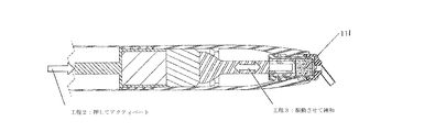
110 カプセル本体の第2膜
111 練和歯科修復材(ペースト)
112 端部(ソノトロード)
113 ソノトロード
114 振動源
20 カプセル
130 送達デバイス
32 平衡重り
33 摺動スリーブ
34 送達デバイスの外側本体
35 ばね
Description of
5
112 End (Sonot Road)
113 Sonot Road 114
以下では、図42〜図45に示すような超音波振動練和について記載する。送達デバイス130及びカプセル20を共に組み合わせて、独立型のアマルガメーター(別名、トリテラター(triterator))を使用する必要がなく、そのため、カプセルをアクティベーターへ、そしてアマルガメーターへ、そして最終的には手動式ディスペンサーへ移す必要がないパッケージング及び送達システムを形成する。このシステムにおいて、カプセル20は、送達システム130内に装填され、全て同じ送達システム130により、アクティベートされ、練和され、分注される。
In the following, ultrasonic vibration kneading as shown in FIGS. 42 to 45 will be described. There is no need to use a stand-alone amalgamator (also known as a triterator) in combination with the
振動源114及びソノトロード113の移動を提供するためにかなり多くの機構を利用することができるため、送達デバイス130の送達端部のみが、本明細書に示され、記載されることに留意すべきである。そのような機構としては、レバーにより機械的に前進するプランジャ、空気圧シリンダー、送りねじ及びナット、圧電リニアモーター、ラック及びピニオン、又は線形移動を提供する他のこのような機構を含むが、これらに限定されない。
It should be noted that only the delivery end of the
カプセル20は、本体4と、ノズル5と、液体容器6と、プランジャ7とからなる。液体容器6は、液体容器6と練和チャンバ9との間に配置される第1膜8を有する。カプセル本体4は、練和チャンバ9とノズル5との間に配置される第2膜110を有する。粉末1及び液体2は、練和歯科修復材111の構成成分であり、カプセル20に入れられ、そこで分離される。液体2は、液体容器6に入れられ、近位端にあるプランジャ7と、遠位端にある第1膜とによって封止される。粉末1は、練和チャンバ9に入れられ、液体容器6と第2膜110により封止される。カプセル20は、送達デバイス130から取り外し可能であることが好ましい。
The
カプセル20をアクティベートするため、プランジャ7は、ソノトロード113の端部112により、軸方向にカプセル20の遠位端に向かって移動する。第1段階の移動により、第1膜8は、液圧力下で破裂して、続いて液体2が練和チャンバ9内に移動する。液体2が練和チャンバ9内へ移されると、軸の移動は、練和のため休止する。振動源114からの振動は、プランジャ7及びカプセル20のカプセル本体7に伝達され、粉末1及び液体2の練和歯科修復材111のペーストへの練和を誘導することが好ましい。振動の時間及び強度は、粉末1の液体2に対する比率、材料の所定量、所望のペースト粘度、及び特有の製剤要件などに応じて可変である。
To activate the
振動源114は、一端はソノトロード113に、他端は、平衡重り32に接続される、複数の圧電部品を備える。平衡重り32は、摺動スリーブ33により囲まれる。送達デバイス30は、ソノトロード113と、振動源114と、平衡重り32と、摺動スリーブ33とを備え、全て送達デバイス130の外側本体34内で移動可能に配置される。この移動可能な配置は、内部移動可能アセンブリと称され、ピストン、プランジャ、結合部、レバー、又は圧電シリンダーなどにより提供される軸方向の力により作用を受け、カプセル20に対して、ソノトロード113の端部112を移動させる。移動は、送達デバイス30及びカプセル20の近位端から遠位端までの方向で作用する。
The vibration source 114 includes a plurality of piezoelectric components having one end connected to the
歯科修復材111が、ペーストへ十分に練和された後、ソノトロード113の端部112は、カプセル20の遠位端に向かって移動し、プランジャ7及び液体容器6をカプセル20の遠位端に向けて移動させる。この第2段階の移動により、第2膜110が、液圧力下で破裂して、練和歯科修復材111を施術部位に送達するためノズル5内に移すことが可能となる。第2段階の移動は、操作者の必要性に応じてペーストの流れを制御するため、操作者により制御することができることが好ましい。
After the
ばね35は、カプセル20を送達デバイス130内に装填することができるよう、送達デバイス130の近位端に向かって内部移動可能アセンブリを付勢する。内部移動可能アセンブリの軸方向の移動の間、ばね35は、圧縮される。分注が完了したとき、空のカプセル20を取り出して処分することができるよう、ばね35の付勢力によって、内部移動可能アセンブリは送達デバイス30の近位端へと戻る。
The
別の実施形態において、ソノトロードは、直接的で確実な接続を通し、カプセル本体に直接的に振動を伝達する。接続は、選択的にロック及びロック解除され、ソノトロードからカプセル本体との接続を断ち、カプセルアクティベーション中のソノトロードの各段階の移動及び練和歯科修復ペーストの送達を容易にする。 In another embodiment, the sonot load transmits vibrations directly to the capsule body through a direct and secure connection. The connection is selectively locked and unlocked, disconnecting the sonot load from the capsule body and facilitating the movement of each stage of the sonot load during capsule activation and the delivery of the kneaded dental restoration paste.
デバイスが2つの流体又はペースト生成物を練和する別の実施形態がある。 There is another embodiment in which the device kneads the two fluid or paste products.
以下では、緩い磁気練和部品及び外部磁場による練和について記載する。カプセルをアクティベートした(液体を粉末に導入する)後、磁場を導入し、球を動かしてペーストの練和を助力する。図46は、どのように球が外部磁石に誘引されるかについて例証する。磁場を、カプセルの周りを移動させて、パルスで変調することができる。また、カプセルは、その縦軸を中心に回転することができ、さらなる練和動作を誘導する。カプセル回転と磁場の適用の組み合わせが合わさることにより、単に回転のみの場合以上に生成物を練和する。 In the following, loose magnetic kneading parts and kneading by an external magnetic field will be described. After activating the capsule (introducing the liquid into the powder), a magnetic field is introduced to move the spheres to help knead the paste. FIG. 46 illustrates how the sphere is attracted to an external magnet. The magnetic field can be moved around the capsule and pulsed. In addition, the capsule can rotate about its vertical axis, inducing a further kneading operation. The combination of capsule rotation and application of magnetic field kneads the product more than just rotation.
練和後、磁場を取り除き、プランジャを押すことにより、生成物を分注する。プランジャが前進すると、円球は、カプセルの前方へと容易に移動し、最終的に図47に示されるように集まる。たとえ、球が密に充填されていたとしても、ペーストは、容易に球の間を通ることができる。 After kneading, the magnetic field is removed and the product is dispensed by pushing the plunger. As the plunger advances, the spheres easily move forward of the capsule and finally gather as shown in FIG. 47. The paste can easily pass between the spheres, even if the spheres are densely packed.
カプセルの前部は、スクリーンのように作用するよう設計される。これは、ペーストは通過させるが、球の通過を防ぐ。カプセル及び球は、通路を妨害することのないよう設計される。 The front of the capsule is designed to act like a screen. This allows the paste to pass but prevents the sphere from passing. Capsules and spheres are designed so as not to obstruct the passage.
出願時の開示に記載されるハンドピースと併せて使用されるとき、カプセルは、他のシステムと比較して独自の競合優位性を有する。1つの優位性としては、球が粉砕(trituration)と干渉しないため、アマルガムミキサーで使用することもできることが挙げられる。同様に、競合するカプセルは、内部磁気ミキサーがなければ、本出願人の新規のハンドピースを動かせないであろう。 When used in conjunction with the handpieces described in the filing disclosure, capsules have a unique competitive advantage over other systems. One advantage is that the spheres do not interfere with trituration and can also be used in amalgam mixers. Similarly, competing capsules would not be able to move Applicant's new handpiece without an internal magnetic mixer.
以下に記載されるカプセルは、カプセルをアクティベートし、練和し、得られるペーストを塗布するディスペンサーと併せて、粉末/液体歯科組成物の練和用の、本明細書に記載されるアプリケーターシステム内での使用に適する。 The capsules described below are in the applicator system described herein for the kneading of powder / liquid dental compositions, along with dispensers that activate, knead and apply the resulting paste. Suitable for use in.
以下段落は、練和シャフトの中央空洞部にて液体を保管する方法及び設計について記載する。 The following paragraphs describe the method and design of storing the liquid in the central cavity of the kneading shaft.
図48は、システムの構成要素を特定する。 FIG. 48 identifies the components of the system.
図49は、ハンドピースプランジャによりアクティベートされるカプセルを例証する。 FIG. 49 illustrates a capsule activated by a handpiece plunger.
図50は、練和段階を例証する。 FIG. 50 illustrates the kneading stage.
図51は、練和が完了したときを例証する。 FIG. 51 illustrates when the kneading is completed.
図52は、完全に押し出されたカプセルを例証する。図53は、ハンドピースプランジャを引き抜いた、空のカプセルを例証する。 FIG. 52 illustrates a fully extruded capsule. FIG. 53 illustrates an empty capsule with the handpiece plunger pulled out.
符号の説明
41 練和ディスク
42 ハンドピース伸長プランジャ
43 第2の移動可能なピストン
44 ドーナツ形状のプランジャ
45 カプセル本体
46 ノズル
47 押し出し管
48 通気穴
49 バヨネットロックタブ
410 バヨネット連結ねじ
411 粉末成分
412 液体成分
413 中空シャフト
414 カプセル
415 ハンドピースドライブシャフト
416 脆い膜
417 第1の移動可能なピストン
418 練和歯科組成物
Description of Code 41 Kneading Disc 42 Handpiece Extension Plunger 43 Second Movable Piston 44 Donut-shaped Plunger 45 Capsule Body 46 Nozzle 47
本明細書では、カプセル414及びハンドピース(明確にするため、ハンドピースのハンドピースドライブシャフト415のみを示す)について記載する。カプセルは、歯科組成物の粉末成分411及び液体成分412を保管及び練和するためのものである。例えば、組成物は、グラスアイオノマー歯科修復材である。ハンドピースはカプセルに作用して、アクティベートし、練和し、練和した歯科組成物を分注する。 This specification describes the capsule 414 and the handpiece (for clarity, only the handpiece drive shaft 415 of the handpiece is shown). The capsule is for storing and kneading the powder component 411 and the liquid component 412 of the dental composition. For example, the composition is a glass ionomer dental restoration material. The handpiece acts on the capsule to activate, knead and dispense the kneaded dental composition.
本明細書に記載されるカプセルは、粉末及び液体成分を塗布のため必要となるまで別々に保つよう構成される。粉末は、カプセル本体45により形成される区画に保管される。液体は、カプセル本体内の中空シャフト413の内側に保管される。液体は、アクティベーション段階中、中空シャフトから排出され、練和チャンバにおいて粉末を湿らす。中空シャフトは、回転及び往復運動し、粉末及び液体をペースト状歯科組成物へと練和する練和ディスク41に接続される。歯科組成物は、カプセルの遠位端にあるノズル46を通してペーストを押し出すことにより、カプセルから分注される。 The capsules described herein are configured to keep the powder and liquid components separate until needed for application. The powder is stored in a compartment formed by the capsule body 45. The liquid is stored inside the hollow shaft 413 inside the capsule body. The liquid is drained from the hollow shaft during the activation phase to moisten the powder in the kneading chamber. The hollow shaft is connected to a kneading disc 41 that rotates and reciprocates to knead the powder and liquid into a paste-like dental composition. The dental composition is dispensed from the capsule by extruding the paste through a nozzle 46 at the distal end of the capsule.
中空シャフトにある液体保管区画は、遠位端には、密で固い端面を、近位端には開放端を有する。中空シャフトの側壁は、シャフトの遠位端近くに、通気穴48を有する。第1の移動可能なピストン417は、通気孔の上に配置され、中空シャフトの端部を封止する。液体成分は、中空シャフトの開放端を通って充填され、中空シャフトの近位端にある第2の移動可能なストッパーを用いて封じ込められる。したがって、液体は、第1の移動可能なピストンと、第2の移動可能なピストンとの間の中央区画に入れられる。
The liquid storage compartment on the hollow shaft has a dense, hard end face at the distal end and an open end at the proximal end. The side wall of the hollow shaft has a
カプセルは、回転及び往復運動して歯科組成物を練和する内部練和ディスクを有する。練和ディスクは、中空シャフトの遠位端に接続される。中空シャフトの軸は、カプセル本体の軸と一致する。中空シャフトの近位端は、ハンドピースのドライブシャフトへ連結するための手段をも有する。ハンドピースドライブシャフトは、カプセルをアクティベートし、練和ディスクを回転及び往復運動する動きを提供する。 The capsule has an internal kneading disc that rotates and reciprocates to knead the dental composition. The kneading disc is connected to the distal end of the hollow shaft. The axis of the hollow shaft coincides with the axis of the capsule body. The proximal end of the hollow shaft also has means for connecting to the drive shaft of the handpiece. The handpiece drive shaft activates the capsule and provides the movement of rotating and reciprocating the kneading disc.
中空シャフトの練和ディスクは、カプセルの練和チャンバの遠位側壁に隣接して配置される。粉末は、液体が充填された中空シャフトを囲む練和チャンバに置かれることが好ましい。カプセルの近位端は、中空シャフト用のベアリングの役割をも果たすドーナツ形状のプランジャ44によって封止される。ドーナツ形状のプランジャのベアリングは、中空シャフトの外面と摩擦により嵌合し、そのため、中空シャフトは、粉末及び練和歯科組成物を入れるための封止を維持しつつ、回転及び往復運動することができる。ドーナツ形状のプランジャは、カプセル本体の内側の壁に対しても摩擦により嵌合し、そのため、カプセルの遠位端に向けて移動して練和歯科組成物を分注することができる。 The hollow shaft kneading disc is located adjacent to the distal side wall of the capsule kneading chamber. The powder is preferably placed in a kneading chamber that surrounds a hollow shaft filled with liquid. The proximal end of the capsule is sealed by a donut-shaped plunger 44 that also acts as a bearing for the hollow shaft. The bearings of the donut-shaped plunger fit by friction with the outer surface of the hollow shaft, so that the hollow shaft can rotate and reciprocate while maintaining a seal for the powder and kneaded dental composition. it can. The donut-shaped plunger also frictionally fits against the inner wall of the capsule body so that it can move towards the distal end of the capsule to dispense the kneaded dental composition.
ハンドピースドライブシャフトは、中空シャフト内に嵌合する伸長プランジャを有する。アクティベーション中、伸長プランジャは前進して、第2の移動可能なピストンに接する。移動により、第1の移動可能なピストンは、液圧力の力によって遠位端に向けて動かされる。第1の移動可能なストッパーの近位縁が通気穴を通ると、液体は、通気穴から粉末がある練和チャンバ内へ流れる。その後、ドライブシャフトの伸長プランジャが第2の移動可能なピストンを中空シャフトの端部へ最後まで移動したとき、すべての液体は、練和チャンバ内へ移動している。 The handpiece drive shaft has an extension plunger that fits within the hollow shaft. During activation, the extension plunger advances and touches a second movable piston. Due to the movement, the first movable piston is moved towards the distal end by the force of hydraulic pressure. When the proximal edge of the first movable stopper passes through the vent, the liquid flows from the vent into the kneading chamber where the powder is located. After that, when the extension plunger of the drive shaft has moved the second movable piston to the end of the hollow shaft to the end, all the liquid has moved into the kneading chamber.
ドライブシャフトは、伸長プランジャの近位端に、バヨネット連結ねじ410を有する。中空シャフトの近位端は、バヨネットロックタブ49を有する。アクティベーション中、ドライブシャフトが、中空シャフトの端部に近づくと、ドライブシャフトは、バヨネットロック形体を係合する方向に回転し始める。一旦連結されると、ドライブシャフトは、連続して回転し始め、その上、前後に往復運動し始め、粉末及び液体をペースト状の粘度へと練和する。方向及び連続回転により、練和部品が往復運動しても、バヨネットロック形体の連結係合は確実にロックを維持する。
The drive shaft has a
所望の粘度に達したとき、押し出し管47が前進して、ドーナツ形状のプランジャを押し進め、練和歯科組成物を外に出す。ドーナツ形状のプランジャと一体で前進する必要があることから、ドライブシャフトは、練和ディスク及び中空シャフトも前進させる。練和ディスクのブレード間の空間により、ペーストが練和ブレードの周りを流れ、ノズルの外へ流れることができる。 When the desired viscosity is reached, the extrusion tube 47 advances to push the donut-shaped plunger forward and pull the kneaded dental composition out. Since it is necessary to advance integrally with the donut-shaped plunger, the drive shaft also advances the kneading disc and the hollow shaft. The space between the blades of the kneading disc allows the paste to flow around the kneading blades and out of the nozzle.
ペーストが押し出されるとき折り畳まれる折り畳み可能な練和ブレードも、先の開示で記載したように利用することができる。 A foldable kneading blade that folds when the paste is extruded can also be used as described in the previous disclosure.
別の実施形態は、液体を練和区画の長さに沿って分散させ、より均等に粉末成分全体に液体を分散させる。 Another embodiment disperses the liquid along the length of the kneading compartment and more evenly disperses the liquid over the entire powder component.
このコンセプトの別の実施形態は、練和ディスクの中を通る穴を有する中空シャフトと、中空シャフトの内端部にあるバイパス液口とを有する。そのため、液体は、中空シャフトの側よりむしろ、練和ディスクの遠位端に移されるであろう。 Another embodiment of this concept has a hollow shaft having a hole through the kneading disc and a bypass liquid port at the inner end of the hollow shaft. Therefore, the liquid will be transferred to the distal end of the kneading disc rather than to the side of the hollow shaft.
Claims (18)
前記ハンドピースは、前記粉末及び前記液体をペーストに練和するようにチャンバをアクティベートすることができ、
前記ハンドピースはさらに、前記ペーストを前記チャンバから分注することができ、
前記チャンバは、回転及び往復運動して、前記粉末及び前記液体を練和する内部練和部品を有し、前記内部練和部品は、前記チャンバの軸と平行であり、前記チャンバの外側の壁に対して軸を中心に回転し、前記液体は、前記内部練和部品を越えて押し進み、前記ペーストを押し出す、ハンドピース。 A handpiece containing a chamber containing a powder and a liquid.
The handpiece can activate the chamber to knead the powder and the liquid into the paste.
The handpiece may further dispensing the paste from the chamber,
The chamber has an internal kneading component that rotates and reciprocates to knead the powder and the liquid, the internal kneading component being parallel to the axis of the chamber and the outer wall of the chamber. A handpiece that rotates about an axis with respect to the liquid and pushes the liquid over the internal kneading parts to push out the paste .
請求項1〜17のいずれか1項に記載のハンドピースと、
を備え、
前記ハンドピースは、前記粉末及び前記液体がペーストに練和されるよう、前記分割カプセルをアクティベートするために引き金を引くことができ、
練和されたペーストは、前記ハンドピースから押し出される、歯科材料アプリケーターシステム。 Divided capsules with powder and liquid,
The handpiece according to any one of claims 1 to 17 ,
With
The handpiece can be triggered to activate the split capsule so that the powder and the liquid are kneaded into the paste.
A dental material applicator system in which the kneaded paste is extruded from the handpiece.
Applications Claiming Priority (3)
| Application Number | Priority Date | Filing Date | Title |
|---|---|---|---|
| US201562129082P | 2015-03-06 | 2015-03-06 | |
| US62/129,082 | 2015-03-06 | ||
| PCT/US2016/021177 WO2016144868A1 (en) | 2015-03-06 | 2016-03-07 | Dental material delivery system |
Publications (2)
| Publication Number | Publication Date |
|---|---|
| JP2018507032A JP2018507032A (en) | 2018-03-15 |
| JP6830439B2 true JP6830439B2 (en) | 2021-02-17 |
Family
ID=55543119
Family Applications (1)
| Application Number | Title | Priority Date | Filing Date |
|---|---|---|---|
| JP2017540773A Active JP6830439B2 (en) | 2015-03-06 | 2016-03-07 | Dental material delivery system |
Country Status (5)
| Country | Link |
|---|---|
| US (2) | US11478332B2 (en) |
| EP (2) | EP3871631A1 (en) |
| JP (1) | JP6830439B2 (en) |
| CA (1) | CA2973765C (en) |
| WO (1) | WO2016144868A1 (en) |
Families Citing this family (2)
| Publication number | Priority date | Publication date | Assignee | Title |
|---|---|---|---|---|
| DE102018122290A1 (en) * | 2018-09-12 | 2020-03-12 | Kulzer Gmbh | Mixing capsule, especially for the dental field |
| EP4032498A1 (en) * | 2021-01-21 | 2022-07-27 | Septodont ou Septodont SAS ou Specialites Septodont | An apparatus for activating a cartridge comprising a multi-component material and/or for mixing by vibration said cartridge |
Family Cites Families (29)
| Publication number | Priority date | Publication date | Assignee | Title |
|---|---|---|---|---|
| US2578180A (en) * | 1948-09-02 | 1951-12-11 | Allis Chalmers Mfg Co | Scrubber with lining and paddles of rubbery materials |
| GB934235A (en) * | 1961-06-12 | 1963-08-14 | Donald George Smith | Improvements in or relating to dental instruments |
| US3204283A (en) * | 1963-10-25 | 1965-09-07 | Lehn & Fink Products Corp | Mixing device |
| US3389468A (en) * | 1964-12-23 | 1968-06-25 | Eugene W. Lewis | Disposable pre-charged dental handpiece |
| SE310754B (en) * | 1967-08-28 | 1969-05-12 | G Bergendal | |
| DE1566294B2 (en) * | 1967-11-23 | 1974-09-05 | Zahn-Porzellan Kg, E. Muehlbauer & Co, 2000 Hamburg | Capsule-shaped multi-component packaging for dental purposes |
| US3715806A (en) * | 1970-03-11 | 1973-02-13 | F Warden | Disposable dental appliance and method for preparing and placing silver amalgam fillings |
| US3724077A (en) * | 1971-11-26 | 1973-04-03 | Unitek Corp | Mixing syringe |
| US3965578A (en) | 1974-09-23 | 1976-06-29 | Grace Development Company | Combined amalgam carrier and dental handpiece |
| US4322022A (en) * | 1980-03-19 | 1982-03-30 | Whirlco, Inc. | Quick release for helically-threaded drive unit |
| DE8907335U1 (en) * | 1989-06-15 | 1990-10-18 | Espe Stiftung & Co Produktions- Und Vertriebs Kg, 8031 Seefeld, De | |
| DE4332308C1 (en) * | 1993-09-23 | 1994-09-29 | Heraeus Kulzer Gmbh | Syringe for the metered dispensing of viscous materials, especially of dental materials |
| JPH08252267A (en) * | 1995-03-17 | 1996-10-01 | Matsumoto Shika Univ | Dental ultrasonic working device |
| WO2003016834A1 (en) * | 2001-08-16 | 2003-02-27 | Closure Medical Corporation | Multiple-component combining |
| JP4182692B2 (en) * | 2002-06-20 | 2008-11-19 | 油化電子株式会社 | Syringe type drug capsule |
| US6889872B2 (en) * | 2002-06-28 | 2005-05-10 | Meritool, L.L.C. | Electric two-part material dispenser |
| US7736049B2 (en) * | 2003-08-21 | 2010-06-15 | Medmix Systems Ag | Device and method for the storage mixing and dispensing components |
| JP4413561B2 (en) * | 2003-09-01 | 2010-02-10 | 株式会社ジーシー | Dental impression mixing mixer |
| EP1532940B1 (en) * | 2003-11-20 | 2011-08-24 | Cattani S.P.A. | A control device for fluid separators in dental aspiration plants |
| US8603805B2 (en) * | 2005-04-22 | 2013-12-10 | Hyclone Laboratories, Inc. | Gas spargers and related container systems |
| EP1736113B1 (en) * | 2005-06-03 | 2009-08-05 | 3M Innovative Properties Company | Dental material processing system and communication method |
| US7776010B2 (en) * | 2006-05-01 | 2010-08-17 | Ultradent Products, Inc. | Syringe-in-syringe hollow inner barrel/plunger with integral seal and rupturable membrane and related kits, systems, and methods |
| BRPI0822342A2 (en) * | 2008-03-13 | 2015-06-16 | Compulz B V | Dough distributor as paste |
| GB0915008D0 (en) * | 2009-08-28 | 2009-09-30 | 3M Innovative Properties Co | Device for dispensing a dental material |
| CH702757A1 (en) * | 2010-02-22 | 2011-08-31 | Medmix Systems Ag | Syringe-like mixing device with distally option for self mixing element. |
| US8690570B2 (en) * | 2010-09-24 | 2014-04-08 | Sdi North America Inc. | Mixing and dispensing container |
| US20120265209A1 (en) * | 2011-04-13 | 2012-10-18 | Kyphon Sarl | Apparatus and methods for mixing materials |
| EP3885144B1 (en) * | 2013-02-04 | 2024-02-28 | Sonendo, Inc. | Dental treatment system |
| AU2014201994B2 (en) * | 2013-04-12 | 2018-08-30 | Sdi Limited | A dental capsule |
-
2016
- 2016-03-07 CA CA2973765A patent/CA2973765C/en active Active
- 2016-03-07 EP EP21158177.2A patent/EP3871631A1/en active Pending
- 2016-03-07 JP JP2017540773A patent/JP6830439B2/en active Active
- 2016-03-07 WO PCT/US2016/021177 patent/WO2016144868A1/en active Application Filing
- 2016-03-07 EP EP16710599.8A patent/EP3265016B1/en active Active
- 2016-03-07 US US15/546,769 patent/US11478332B2/en active Active
-
2022
- 2022-09-26 US US17/952,470 patent/US20230013268A1/en active Pending
Also Published As
| Publication number | Publication date |
|---|---|
| EP3265016A1 (en) | 2018-01-10 |
| US20230013268A1 (en) | 2023-01-19 |
| US11478332B2 (en) | 2022-10-25 |
| CA2973765C (en) | 2024-01-30 |
| WO2016144868A1 (en) | 2016-09-15 |
| US20180000561A1 (en) | 2018-01-04 |
| CA2973765A1 (en) | 2016-09-15 |
| JP2018507032A (en) | 2018-03-15 |
| EP3265016B1 (en) | 2023-10-25 |
| EP3871631A1 (en) | 2021-09-01 |
Similar Documents
| Publication | Publication Date | Title |
|---|---|---|
| DK2944380T3 (en) | DEVICE AND PROCEDURE FOR MIXING A MULTI-COMPONENT CEMENT | |
| US20230013268A1 (en) | Dental material delivery system | |
| JP6529094B2 (en) | Bone cement applicator with three-way valve for pressure relief | |
| US8608030B2 (en) | Cartridge system with compressed gas cartridge | |
| JP5669458B2 (en) | Disposable cartridge for storing and delivering two-component dental impression material | |
| JP2007511296A (en) | Mixing and dispensing device for osteosynthesis with composite components | |
| US11109905B2 (en) | Bone cement applicator with retractable mixing rod and method for production of a bone cement | |
| US20050105384A1 (en) | Apparatus for mixing and dispensing a multi-component bone cement | |
| JP6890648B2 (en) | A device for mixing bone cement with a hollow space for monomer transfer | |
| WO2011098744A1 (en) | Device for administering a viscous substance during a surgical operation | |
| US6030214A (en) | Manual device for delivering a viscous fluid | |
| CA2972484C (en) | Bone cement applicator with three-way valve for pressure relief | |
| US11109906B2 (en) | Bone cement applicator with retractable mixing rod and method for production of a bone cement | |
| WO2022152824A1 (en) | Applicator for robot-assisted surgery | |
| AU2022208338A1 (en) | Applicator for robot-assisted surgery | |
| CN116867443A (en) | Applicator for robotic assisted surgery |
Legal Events
| Date | Code | Title | Description |
|---|---|---|---|
| A621 | Written request for application examination |
Free format text: JAPANESE INTERMEDIATE CODE: A621 Effective date: 20190214 |
|
| A977 | Report on retrieval |
Free format text: JAPANESE INTERMEDIATE CODE: A971007 Effective date: 20200114 |
|
| A131 | Notification of reasons for refusal |
Free format text: JAPANESE INTERMEDIATE CODE: A131 Effective date: 20200303 |
|
| A601 | Written request for extension of time |
Free format text: JAPANESE INTERMEDIATE CODE: A601 Effective date: 20200409 |
|
| A521 | Request for written amendment filed |
Free format text: JAPANESE INTERMEDIATE CODE: A523 Effective date: 20200731 |
|
| TRDD | Decision of grant or rejection written | ||
| A01 | Written decision to grant a patent or to grant a registration (utility model) |
Free format text: JAPANESE INTERMEDIATE CODE: A01 Effective date: 20210105 |
|
| A61 | First payment of annual fees (during grant procedure) |
Free format text: JAPANESE INTERMEDIATE CODE: A61 Effective date: 20210126 |
|
| R150 | Certificate of patent or registration of utility model |
Ref document number: 6830439 Country of ref document: JP Free format text: JAPANESE INTERMEDIATE CODE: R150 |
|
| R250 | Receipt of annual fees |
Free format text: JAPANESE INTERMEDIATE CODE: R250 |