JP6830258B2 - Wire lead-in structure and wire lead-in tool - Google Patents
Wire lead-in structure and wire lead-in tool Download PDFInfo
- Publication number
- JP6830258B2 JP6830258B2 JP2018093902A JP2018093902A JP6830258B2 JP 6830258 B2 JP6830258 B2 JP 6830258B2 JP 2018093902 A JP2018093902 A JP 2018093902A JP 2018093902 A JP2018093902 A JP 2018093902A JP 6830258 B2 JP6830258 B2 JP 6830258B2
- Authority
- JP
- Japan
- Prior art keywords
- wire rod
- main body
- opening
- body member
- peripheral wall
- Prior art date
- Legal status (The legal status is an assumption and is not a legal conclusion. Google has not performed a legal analysis and makes no representation as to the accuracy of the status listed.)
- Active
Links
- 239000000463 material Substances 0.000 claims description 96
- 230000002093 peripheral effect Effects 0.000 claims description 57
- 239000000758 substrate Substances 0.000 claims description 32
- 238000005491 wire drawing Methods 0.000 claims description 13
- 230000000149 penetrating effect Effects 0.000 claims description 7
- 238000013459 approach Methods 0.000 claims description 5
- XLYOFNOQVPJJNP-UHFFFAOYSA-N water Substances O XLYOFNOQVPJJNP-UHFFFAOYSA-N 0.000 description 17
- 238000003780 insertion Methods 0.000 description 8
- 230000037431 insertion Effects 0.000 description 8
- 230000000694 effects Effects 0.000 description 4
- 230000005494 condensation Effects 0.000 description 3
- 238000009833 condensation Methods 0.000 description 3
- 238000005553 drilling Methods 0.000 description 3
- 238000000034 method Methods 0.000 description 3
- 239000010454 slate Substances 0.000 description 3
- 229910000838 Al alloy Inorganic materials 0.000 description 2
- 239000010426 asphalt Substances 0.000 description 2
- 238000005266 casting Methods 0.000 description 2
- 238000010276 construction Methods 0.000 description 2
- 229920001821 foam rubber Polymers 0.000 description 2
- 229910052751 metal Inorganic materials 0.000 description 2
- 239000002184 metal Substances 0.000 description 2
- 229920003002 synthetic resin Polymers 0.000 description 2
- 239000000057 synthetic resin Substances 0.000 description 2
- 229920005549 butyl rubber Polymers 0.000 description 1
- 238000004891 communication Methods 0.000 description 1
- 238000007796 conventional method Methods 0.000 description 1
- 238000005520 cutting process Methods 0.000 description 1
- 238000013461 design Methods 0.000 description 1
- 238000009826 distribution Methods 0.000 description 1
- 230000008595 infiltration Effects 0.000 description 1
- 238000001764 infiltration Methods 0.000 description 1
- 238000001746 injection moulding Methods 0.000 description 1
- 238000004519 manufacturing process Methods 0.000 description 1
- 238000000465 moulding Methods 0.000 description 1
- 238000004078 waterproofing Methods 0.000 description 1
Images


Classifications
-
- Y—GENERAL TAGGING OF NEW TECHNOLOGICAL DEVELOPMENTS; GENERAL TAGGING OF CROSS-SECTIONAL TECHNOLOGIES SPANNING OVER SEVERAL SECTIONS OF THE IPC; TECHNICAL SUBJECTS COVERED BY FORMER USPC CROSS-REFERENCE ART COLLECTIONS [XRACs] AND DIGESTS
- Y02—TECHNOLOGIES OR APPLICATIONS FOR MITIGATION OR ADAPTATION AGAINST CLIMATE CHANGE
- Y02B—CLIMATE CHANGE MITIGATION TECHNOLOGIES RELATED TO BUILDINGS, e.g. HOUSING, HOUSE APPLIANCES OR RELATED END-USER APPLICATIONS
- Y02B10/00—Integration of renewable energy sources in buildings
- Y02B10/10—Photovoltaic [PV]
Landscapes
- Roof Covering Using Slabs Or Stiff Sheets (AREA)
Description
本発明は、屋根材の上から線材引込具を介して建物内へ線材が引込まれている線材引込構造及び線材引込具に関するものである。 The present invention relates to a wire rod pull-in structure and a wire rod pull-in tool in which a wire rod is pulled into a building from above the roof material via a wire rod pull-in tool.
本出願人は過去に、建物の屋根を構成する垂木や野地板等の屋根構造体に敷設された屋根材上から建物内へ、太陽電池モジュールからの電線や、テレビアンテナからのアンテナ線等の線材を引込むための線材引込具を提案している(特許文献1及び特許文献2)。これらの線材引込具は、上端面及び軒側端面が開放されている容器状の本体部材と、本体部材の上方を覆う蓋部材と、を備えている。本体部材は、容器状の内部に、上下に貫通している挿通孔が形成されている。 In the past, the applicant has applied electric wires from the solar cell module, antenna wires from the TV antenna, etc. from the roofing material laid on the roof structure such as rafters and field boards that make up the roof of the building into the building. We have proposed a wire rod pulling tool for pulling in a wire rod (Patent Document 1 and Patent Document 2). These wire drawing tools include a container-shaped main body member whose upper end surface and eaves side end surface are open, and a lid member that covers the upper part of the main body member. The main body member has an insertion hole that penetrates vertically inside the container shape.
上記の線材引込具の屋根材への取付けは、まず、屋根構造体及び屋根材に形成した貫通孔に対して、挿通孔が一致するように本体部材を屋根材上に取付ける。そして、軒側端面から線材を本体部材の内部に導入し、挿通孔及び貫通孔を通して建物内へ延出させる。その後、本体部材に上方から蓋部材を取付けることにより、線材の引込みと線材引込具の取付けとが完了する。このように、線材引込具を介して建物内に線材を引込ませることにより、線材を伝った雨水の建物内への浸入が防止される。 In the attachment of the wire rod retractor to the roof material, first, the main body member is attached to the roof material so that the insertion holes match the through holes formed in the roof structure and the roof material. Then, the wire rod is introduced into the main body member from the eaves side end face and extends into the building through the insertion hole and the through hole. After that, by attaching the lid member to the main body member from above, the drawing of the wire rod and the attachment of the wire rod pulling tool are completed. In this way, by pulling the wire into the building through the wire pulling tool, rainwater that has traveled through the wire can be prevented from entering the building.
上記の線材引込具では、屋根構造体及び屋根材に形成した貫通孔への線材の接触を防止すると共に、屋根構造体の下方への雨水の浸入を防止するための、筒状の部材又は筒状の部位を有している。具体的には、特許文献1の線材引込具では、本体部材の上方から挿通孔を通して貫通孔に挿入される筒状のスリーブ材を有している。また、特許文献2の線材引込具では、貫通孔に挿入される筒状のガイド部が本体部材に一体に設けられている。
In the above-mentioned wire rod pulling tool, a tubular member or a cylinder for preventing the wire rod from coming into contact with the roof structure and the through hole formed in the roof material and preventing rainwater from entering below the roof structure. It has a shaped part. Specifically, the wire rod retracting tool of Patent Document 1 has a tubular sleeve material that is inserted into the through hole from above the main body member through the insertion hole. Further, in the wire rod retracting tool of
しかしながら、特許文献1の技術では、本体部材の挿通孔が貫通孔とずれた状態で本体部材が屋根材に取付けられてしまうと、スリーブ材を挿入することができなくなる恐れがあった。また、特許文献1の技術では、本体部材の上方からスリーブ材を挿通孔及び貫通孔に挿入していることから、スリーブ材の挿入が不十分な状態でも本体部材に蓋部材を取付けることが可能であるため、そのような状態で取付けられた場合、スリーブ材と挿通孔及び貫通孔との間を通して、建物内へ雨水が浸入してしまう恐れがある。 However, in the technique of Patent Document 1, if the main body member is attached to the roofing material in a state where the insertion hole of the main body member is deviated from the through hole, there is a risk that the sleeve material cannot be inserted. Further, in the technique of Patent Document 1, since the sleeve material is inserted into the insertion hole and the through hole from above the main body member, the lid member can be attached to the main body member even when the sleeve material is insufficiently inserted. Therefore, if it is installed in such a state, rainwater may infiltrate into the building through between the sleeve material and the insertion hole and the through hole.
一方、特許文献2の技術では、屋根材の上面に対する垂直方向から貫通孔が傾いて形成されると、ガイド部を貫通孔に挿入して本体部材を屋根材上に取付ける際に、本体部材の下面が屋根材の上面に対して傾いた状態となり、本体部材を屋根材に取付けることができなくなる恐れがあった。
On the other hand, in the technique of
このようなことから、特許文献1や特許文献2のような従来の技術では、本体部材の取付作業や、屋根構造体及び屋根材への貫通孔の孔明作業を、慎重に行う必要があり、線材の引込作業に手間や時間を要していた。
For this reason, in the conventional techniques such as Patent Document 1 and
そこで、本発明は、上記の実情に鑑み、建物内への雨水の浸入を防止すると共に線材の引込作業が容易な線材引込構造及び線材引込具の提供を課題とするものである。 Therefore, in view of the above circumstances, it is an object of the present invention to provide a wire rod pull-in structure and a wire rod pull-in tool that prevent rainwater from entering the building and facilitate the wire rod pull-in work.
上記の課題を解決するために、本発明に係る線材引込構造は、「屋根構造体に敷設された屋根材の上から線材引込具を介して建物内へ線材が引込まれている線材引込構造であって、前記線材引込具は、屋根材及び屋根構造体を貫通している筒状の案内部、及び該案内部の上端から外方へ延出している鍔部を有している案内部材と、該案内部材の上方を覆うように前記屋根材上に取付けられている平板状の基板部、前記鍔部の直径よりも大きく前記基板部を貫通しており前記鍔部が挿入されている開口部、該開口部の内周面から内方へ突出しており前記鍔部の上方へ延出している突起部、前記基板部から上方へ延出しており軒側を開放した状態で前記開口部を囲んでいる周壁部を有している本体部材と、該本体部材に取付けられており、前記周壁部を外側から覆うと共に前記周壁部を上方から閉鎖している蓋部材とを具備し、線材が、軒側から前記周壁部の内部に導入されていると共に、前記開口部及び前記案内部を通って建物内に引込まれている」ものである。 In order to solve the above problems, the wire rod lead-in structure according to the present invention is a wire rod lead-in structure in which the wire rod is drawn into the building from above the roof material laid on the roof structure via the wire rod pull-in tool. The wire rod retracting tool includes a guide member having a tubular guide portion penetrating the roof material and the roof structure, and a flange portion extending outward from the upper end of the guide portion. , A flat plate-shaped substrate portion mounted on the roofing material so as to cover the upper part of the guide member, an opening larger than the diameter of the flange portion and penetrating the substrate portion into which the flange portion is inserted. The opening is opened in a state where the portion, the protrusion extending inward from the inner peripheral surface of the opening and extending upward from the flange, and the eaves extending upward from the substrate portion. The wire rod includes a main body member having a surrounding peripheral wall portion and a lid member attached to the main body member that covers the peripheral wall portion from the outside and closes the peripheral wall portion from above. , It is introduced from the eaves side into the peripheral wall portion, and is drawn into the building through the opening and the guide portion. "
ここで、「屋根構造体」としては、野地板、垂木、を例示することができる。また、「屋根材」としては、板金屋根材、スレート、アスファルトシングル、瓦、を例示することができる。 Here, examples of the "roof structure" include field boards and rafters. Moreover, as a "roofing material", a sheet metal roofing material, a slate, an asphalt single, and a roof tile can be exemplified.
また、「線材」としては、「太陽電池モジュール、風力発電装置、商用電力線、照明装置、等に接続される電線」、「アンテナに接続されるアンテナ線」、「電話やインターネット、ケーブルテレビ等に接続される通信線」、「太陽熱温水器やスプリンクラー等に接続される配水管」、「空調装置に接続される配管」、「ガス管等のその他の配管」、を例示することができる。 In addition, "wires" include "electric wires connected to solar cell modules, wind power generators, commercial power lines, lighting devices, etc.", "antenna wires connected to antennas", "telephones, the Internet, cable TV, etc." Examples thereof include "connected communication lines", "water distribution pipes connected to solar water heaters, sprinklers, etc.", "pipes connected to air conditioners", and "other pipes such as gas pipes".
本構成の線材引込構造は、屋根材及び屋根構造体に形成した貫通孔に案内部材を上方から挿入し、開口部内に案内部材の上端の鍔部が嵌合されるように、本体部材を上方から屋根材上に取付ける。そして、線材を、周壁部の開放されている軒側から本体部材の内側へ延出させると共に、開口部及び案内部材を通して建物内へ引込み、本体部材に蓋部材を上から取付けることにより構築することができる。 In the wire rod lead-in structure of this configuration, the guide member is inserted from above into the roofing material and the through hole formed in the roof structure, and the main body member is moved upward so that the flange portion at the upper end of the guide member is fitted into the opening. Install on the roofing material. Then, the wire rod is extended from the open eaves side of the peripheral wall portion to the inside of the main body member, and is drawn into the building through the opening and the guide member, and the lid member is attached to the main body member from above. Can be done.
本構成の線材引込構造によれば、本体部材の開口部において、案内部材の鍔部の上方へ延出している突起部を有しているため、貫通孔への案内部の挿入が不十分で、鍔部が屋根材から上方へ高く突出していても、本体部材を屋根材上に取付ける際に、突起部が鍔部に当接して案内部材を下方へ押圧することができる。これにより、貫通孔に対して案内部を十分に挿入させることができ、案内部材と貫通孔との間を通した建物内への雨水の浸入を防止することができる。 According to the wire rod lead-in structure of this configuration, the opening of the main body member has a protrusion extending above the flange of the guide member, so that the guide portion cannot be sufficiently inserted into the through hole. Even if the collar portion protrudes upward from the roof material, the protrusion can abut on the collar portion and press the guide member downward when the main body member is mounted on the roof material. As a result, the guide portion can be sufficiently inserted into the through hole, and rainwater can be prevented from entering the building through the guide member and the through hole.
また、本構成の線材引込構造によれば、案内部材を、本体部材の下方に位置させた別部材としているため、屋根材及び屋根構造体の貫通孔に挿入されて屋根材上に突出している案内部材の鍔部に対して、開口部が嵌合されるように本体部材を屋根材上に載置すれば良く、本体部材の取付作業を容易なものとすることができる。また、案内部材を本体部材とは別部材としているため、貫通孔が屋根材上面に対する垂直方向から傾いていたとしても、本体部材を屋根材上に取付けることができ、従来のように孔あけ作業を慎重に行う必要はない。 Further, according to the wire rod lead-in structure of the present configuration, since the guide member is a separate member located below the main body member, it is inserted into the through hole of the roofing material and the roof structure and protrudes onto the roofing material. The main body member may be placed on the roof material so that the opening is fitted to the flange portion of the guide member, and the attachment work of the main body member can be facilitated. Further, since the guide member is a separate member from the main body member, the main body member can be mounted on the roofing material even if the through hole is tilted from the direction perpendicular to the upper surface of the roofing material, and the drilling work as in the conventional case. You don't have to be careful.
また、本発明に係る線材引込構造は、上記の構成に加えて、「前記蓋部材は、軒側へ向かうほど前記基板部に接近するように傾斜している」ものとすることができる。 Further, in the wire rod lead-in structure according to the present invention, in addition to the above configuration, "the lid member is inclined so as to approach the substrate portion toward the eaves side".
ところで、線材引込構造において、線材が挿通される線材引込具の内部では、本体部材の開口部及び案内部材を通して建物内と連通しているため、外気の温度が低い時に、開口部及び案内部材を通して建物内の暖かい空気が線材引込具の内部に導入されると、線材引込具の内部で結露が発生する。この際に、線材引込具が取付けられている屋根の傾斜が緩いと、蓋部材の内側で結露した水が軒方向へ流れ難くなり、水滴となって開口部及び案内部材を通して建物内へ落下してしまう恐れがある。 By the way, in the wire rod lead-in structure, the inside of the wire rod lead-in tool through which the wire rod is inserted communicates with the inside of the building through the opening of the main body member and the guide member, so that the opening and the guide member are passed through when the temperature of the outside air is low. When warm air in the building is introduced into the wire pull-in tool, dew condensation occurs inside the wire lead-in tool. At this time, if the slope of the roof to which the wire drawing tool is attached is gentle, it becomes difficult for the condensed water inside the lid member to flow toward the eaves, and it becomes water droplets and falls into the building through the opening and the guide member. There is a risk that it will end up.
本構成の線材引込構造によれば、蓋部材を、本体部材の基板部に対して軒側が低くなるように傾斜させているため、蓋部材の内側で結露した水を軒方向へ流れ易くすることができ、結露した水が開口部へ向かって落下することを防止することができる。従って、本構成の線材引込構造を傾斜が緩い屋根に構築した場合でも、線材引込具の内部で結露した水が建物内へ落下してしまうことを回避させることができる。 According to the wire drawing structure of this configuration, the lid member is inclined so that the eaves side is lower than the substrate portion of the main body member, so that the water condensed inside the lid member can easily flow toward the eaves. It is possible to prevent the condensed water from falling toward the opening. Therefore, even when the wire rod lead-in structure of this configuration is constructed on a roof with a gentle slope, it is possible to prevent the water condensed inside the wire rod lead-in tool from falling into the building.
本発明に係る線材引込具は、「筒状の案内部、及び該案内部の上端から外方へ延出している鍔部を有している案内部材と、該案内部材の上方を覆っている平板状の基板部、前記鍔部の直径よりも大きく前記基板部を貫通しており前記鍔部が挿入されている開口部、該開口部の内周面から内方へ突出しており前記鍔部の上方へ延出している突起部、及び前記基板部から上方へ延出しており一部を開放した状態で前記開口部を囲んでいる周壁部を有している本体部材と、該本体部材に取付けられ、前記周壁部を外側から覆うと共に前記周壁部を上方から閉鎖している蓋部材とを具備している」ものである。 The wire rod pulling tool according to the present invention covers "a guide member having a tubular guide portion and a flange portion extending outward from the upper end of the guide portion, and an upper portion of the guide member. A flat substrate portion, an opening that is larger than the diameter of the flange portion and penetrates the substrate portion and into which the collar portion is inserted, and an opening that protrudes inward from the inner peripheral surface of the opening portion. A main body member having a protrusion extending upward and a peripheral wall portion extending upward from the substrate portion and surrounding the opening in a partially opened state, and the main body member. It is attached and includes a lid member that covers the peripheral wall portion from the outside and closes the peripheral wall portion from above. "
本構成の線材引込具は、上記の線材引込構造に使用されるものである。この線材引込具は、周壁部の開放されている部位を軒側へ向けて使用する。また、本体部材において開口部の内周面から内方へ突起部を延出させているため、当該線材引込具を取付ける際に、貫通孔への案内部の挿入が不十分な場合、突起部が鍔部に当接して案内部材を下方へ押圧することができる。このように、この線材引込具を使用して線材を建物内へ引込むようにすることにより、上記の作用効果が発揮される。加えて、本構成の線材引込具は、案内部材を本体部材とは別部材としているため、案内部材と本体部材とを一体にした場合と比較して、本体部材を成形するための金型を小さくすることができ、製造にかかるコストの増加を抑制させることができる。 The wire rod pulling tool having this configuration is used for the above wire rod pulling structure. This wire drawing tool is used with the open part of the peripheral wall facing the eaves side. Further, since the protrusion is extended inward from the inner peripheral surface of the opening in the main body member, when the wire rod retracting tool is attached, if the guide portion is not sufficiently inserted into the through hole, the protrusion Can abut on the collar and press the guide member downward. In this way, by using this wire rod pulling tool to pull the wire rod into the building, the above-mentioned action and effect are exhibited. In addition, since the wire pulling tool of this configuration uses the guide member as a separate member from the main body member, a mold for molding the main body member is required as compared with the case where the guide member and the main body member are integrated. It can be made smaller, and an increase in manufacturing cost can be suppressed.
以上のように、本発明の効果として、建物内への雨水の浸入を防止すると共に線材の引込作業が容易な線材引込構造及び線材引込具を提供することができる。 As described above, as an effect of the present invention, it is possible to provide a wire rod drawing structure and a wire rod drawing tool that can prevent rainwater from entering the building and facilitate the wire rod drawing work.
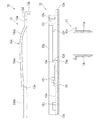
本発明の一実施形態である線材引込具10、及び線材引込具10を使用した線材引込構造について、図1乃至図6を参照して詳細に説明する。本実施形態の線材引込具10は、屋根構造体1に敷設された屋根材2の上から建物内へ線材3を引込むためのものである。
A wire
線材引込具10は、図2乃至図4示すように、筒状の案内部材11と、案内部材11の上方を覆う本体部材12と、本体部材12に上方から取付けられる蓋部材13と、を備えている。また、線材引込具10は、案内部材11の外周を覆う筒状の第一防水材14と、本体部材12の下面に貼り付けられる第二防水材15と、案内部材11の内部に充填される第三防水材16と、蓋部材13の下面に取付けられる第四防水材17と、を備えている。線材引込具10の平面視において、本体部材12の外形は略長方形であり、以下では、本体部材12の長辺と平行な方向を長手方向と称すると共に、長手方向に直交する方向を幅方向と称する。
As shown in FIGS. 2 to 4, the wire
案内部材11は、筒状の案内部11aと、案内部11aの一方の端部から外方へ延出している鍔部11bと、を有している。
The
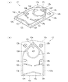
本体部材12は、主に図5に示すように、外形が略長方形の平板状の基板部12aと、基板部12aの長手方向の中央よりも一方の短辺に近い側で貫通している開口部12dと、開口部12dの周囲から上方へ筒状に短く延出している円筒堰部12eと、開口部12d内に突出している平板状の突起部12fと、を有している。開口部12dは、内径が上下方向に一定であり、突起部12fを除いた部位が上方へ開放されている。
As shown mainly in FIG. 5, the
基板部12aの一方の短辺(以下、棟側短辺12bと称す)は、中央を頂点にして両外側へ向かうに従って反対側の短辺(以下、軒側短辺12cと称す)に近付くように屈曲している。開口部12dの内径は、案内部材11の鍔部11bの外径よりも大きく形成されている。基板部12aの底面から円筒堰部12eの上面までの距離は、案内部材11の鍔部11bの厚さよりも長い。
One short side of the
突起部12fは、開口部12dの内周面における棟側短辺12b側から内方(軒側短辺12c側)へ向かって突出している。突起部12fは、上面が円筒堰部12eの上面と一致しており、下面が基板部12aの下面から鍔部11bの厚さ分よりも上方に位置している。
The
また、本体部材12は、基板部12aから上方へ延出している周壁部12gを、有している。周壁部12gは、開口部12dを棟側短辺12b側から軒側短辺12cに向かって囲んでいるが、軒側短辺12c側は開放されている。周壁部12gの高さは、円筒堰部12eの高さの2倍である。
Further, the
周壁部12gは、図5(b)に示すように、平面視において、棟側短辺12bからの距離が、幅方向の中央で最も小さく、両側へ向かうほど離れるように傾斜した状態で、基板部12aの長辺付近まで延出している。そして、基板部12aの長辺付近で屈曲して、長辺と平行に軒側短辺12cまで延出している。周壁部12gの上面には、棟側短辺12bに近い端部付近と、軒側短辺12cに近い端部付近に、蓋部材13を取付けるためのネジ孔12hが形成されている。
As shown in FIG. 5B, the
更に、本体部材12は、一対の第一堰部12iと、第二堰部12jと、を有している。第一堰部12iは、夫々周壁部12gの内側で、開口部12dと軒側短辺12cとの間で基板部12aから周壁部12gよりも低く上方へ延出している。第二堰部12jは、一対の第一堰部12iよりも軒側短辺12c側で基板部12aから周壁部12gよりも低く上方へ延出している。
Further, the
一対の第一堰部12iは、周壁部12gにおける平行に延出している部位の内周面から幅方向の中央側へ向かうほど軒側短辺12cに近付くように斜めに延出している。一対の第一堰部12iは、幅方向の中央側の端部が自由端となっている。一対の第一堰部12iは、開口部12dを長手方向に投影した場合の範囲に含まれる部位が、その外側の部位よりも高さが低く形成されている。一対の第一堰部12iにおける高い部位は、周壁部12gの高さの3/4の高さであり、低い部位は、周壁部12gの高さの1/3の高さである。
The pair of
第二堰部12jは、幅方向中央が棟側短辺12b側へ突出するように屈曲しており、周壁部12gに近い両端部が自由端となっている。第二堰部12jの高さは、円筒堰部12eの高さと同じである。つまり、第二堰部12jは、第一堰部12iにおける低い部位よりも高く形成されている。
The
また、本体部材12は、基板部12aを貫通している複数の取付孔12kを、有している。取付孔12kは、周壁部12gの外側で棟側短辺12bの両端付近の部位と、一対の第一堰部12iよりも棟側短辺12b側の部位との、四箇所に設けられている。取付孔12kは、本体部材12を屋根材2上に取付けるための後述する取付ビス18が挿通されるものである。取付孔12kの周縁部は、基板部12aの上面よりも高く形成されている。
Further, the
また、本体部材12は、周壁部12gにおける開口部12dに近いネジ孔12hと周壁部12gの内周面との間に、溝部12lを、有している。
Further, the
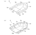
蓋部材13は、平板状で枠状の載置部13aと、載置部13aの外周縁から下方へ延出している蓋周壁部13bと、載置部13aの枠内を閉鎖しており載置部13aよりも上方へ膨出している天壁部13cと、を有している。また、蓋部材13は、載置部13aを貫通している複数の組立孔13dと、天壁部13cの下面から下方へ延出している一対の突壁部13eと、を有している(図6を参照)。
The
載置部13aの外形は、本体部材12の周壁部12gの外形よりもやや大きい略相似形状である。蓋周壁部13bは、本体部材12の周壁部12gの高さの1/2の長さで下方へ延出している。
The outer shape of the mounting
天壁部13cは、平面視において、載置部13aの枠内の中央部に位置している天壁中央部13caと、天壁中央部13caから軒側短辺12c側へ延出している天壁後部13cbと、天壁中央部13ca及び天壁後部13cbの幅方向の端縁と載置部13aの内周縁とを繋いでいる天壁周縁部13ccと、を有している。
In a plan view, the
天壁中央部13caは、載置部13aよりも上方に位置しており、棟側短辺12b側から軒側短辺12c側へ向かうほど低くなるように傾斜している(図4を参照)。天壁中央部13caは、線材引込具10が組立てられた状態で、棟側短辺12bに近い端縁が、本体部材12の開口部12dの中心の上方に位置しており、軒側短辺12cに近い端縁が、第一堰部12iよりも軒側短辺12c側に位置している。
The central portion 13ca of the top wall is located above the mounting
天壁後部13cbは、天壁中央部13caの軒側短辺12cに近い端縁から、長手方向における位置が載置部13aの軒側短辺12cに近い端縁と同じ位置まで、載置部13aと平行に延出している。天壁中央部13ca及び天壁後部13cbは、平坦である。一方、天壁周縁部13ccは、湾曲面であり、天壁中央部13ca及び天壁後部13cbに連続するように繋がっている。
The top wall rear portion 13cc is a mounting portion from the edge of the top wall central portion 13ca near the eaves side
組立孔13dは、本体部材12の三つのネジ孔12hと対応する部位に形成されている。一対の突壁部13eは、天壁周縁部13ccの下面において長手方向の位置が天壁中央部13caと天壁後部13cbと同じ位置から下方へ延出している。突壁部13eの下面は、載置部13aの下面と同一面上にある。
The
第一防水材14は、詳細は後述するが、線材引込具10を取付ける施工現場において、シート状の部材を円筒状に丸めた上で、上端部に、複数の切込を入れて外方へ屈曲させたものである。この第一防水材14は、両面に剥離紙が貼られたシート状の状態のままで出荷時される。第二防水材15は、本体部材12の基板部12aの外形よりも一回り小さいシート状で、開口部12dと対応する部位に開口部12dよりも内径が大きい孔15aが形成されている。第二防水材15は、製品の出荷時に、予め本体部材12の下面に貼り付けられている。第一防水材14及び第二防水材15は、ブチルゴムシートにより形成されている。
The details of the first
第三防水材16は、プラシール(登録商標)のような耐水性や防水性や絶縁性を有した合成樹脂からなるパテである。第三防水材16は、製品の出荷時に、所定量が同梱されている。第四防水材17は、発泡ゴムである。第四防水材17は、製品の出荷時に、予め、蓋部材13の天壁部13cの下面において、一対の突壁部13eよりも軒側短辺12c側の部位に、幅方向の全長に亘って貼り付けられている。
The third
線材引込具10の案内部材11は、合成樹脂の射出成形、又はアルミニウム合金の鋳造、の何れかにより形成されている。また、本体部材12及び蓋部材13は、アルミニウム合金の鋳造により形成されている。
The
続いて、上記の線材引込具10を使用して屋根材2の上から建物内へ線材3を引込む線材引込構造の構築について説明する。本実施形態では、屋根構造体1が野地板、屋根材2がスレート、である場合を例示する。
Subsequently, the construction of a wire rod pulling structure for pulling the
まず、屋根材2における線材引込具10を取付ける部位に、屋根材2及び屋根構造体1を貫通するように、上方から案内部材11の案内部11aの直径よりも若干大きい内径の貫通孔4を形成する。次に、シート状の第一防水材14の片方の面の剥離紙を剥がし、屋根材2の上面から上端をある程度突出させた状態で、剥離紙を剥がした面を外側にして貫通孔4の内周面に貼り付けながら巻き付ける。そして、貫通孔4の周方向において重なっている部分を切除した上で、屋根材2の上面から突出している部位に複数の切込を入れて外方へ屈曲させ、屋根材2の上面にも貼り付ける。
First, a through hole 4 having an inner diameter slightly larger than the diameter of the
その後、第一防水材14の残りの面の剥離紙を剥がした上で、第一防水材14の筒状になっている部位に、鍔部11bを上に向けた状態の案内部材11の案内部11aを挿入する。この際に、第一防水材14において案内部材11の鍔部11bの下面が、第一防水材14における屋根材2上に貼り付けられている部位に当接するように、案内部材11を圧入する。これにより、案内部材11と貫通孔4との間が第一防水材14により封止され、建物内への雨水の浸入を防止することができる。
After that, after peeling off the release paper on the remaining surface of the first
次に、基板部12aの下面に第二防水材15が貼り付けられた状態の本体部材12を、棟側短辺12bを棟側へ向けた状態で、開口部12d内に案内部材11の鍔部11bが挿入されるように屋根材2に載置する。そして、上方から取付孔12kに通した取付ビス18を屋根構造体1までねじ込んで、本体部材12を屋根材2上に取付ける。
Next, the
この際に、案内部材11の貫通孔4への挿入が不十分で、鍔部11bが屋根材2から上方へ高く突出していた場合、本体部材12の突起部12fが上方から鍔部11bに当接し、取付ビス18の締付けにより本体部材12が下方へ移動することで、突起部12fが案内部材11を下方へ押圧する。これにより、案内部材11が貫通孔4に十分に挿入された状態となる。
At this time, if the
本体部材12を屋根材2に取付けたら、線材3を上方から開口部12d及び案内部11aへ挿通して建物内へ引込ませると共に、開口部12dの上方で軒側へ屈曲させて周壁部12gの開放されている軒側短辺12c側から軒側へ延出させる。この際に、線材3を、第一堰部12iにおける低い部位の上方を通るようにする。また、複数の線材3を建物内へ引込む場合は、開口部12dよりも軒側では幅方向に並べる。
After the
そして、開口部12d及び案内部材11と、線材3との間を埋めるように、粘土状の第三防水材16を上方から開口部12d及び案内部11aの内部に充填して止水する(図2を参照)。その後、本体部材12の上方から蓋部材13を被せ、組立孔13dを通した取付ネジ19をネジ孔12hにねじ込んで締付ける。この際に、蓋部材13の下面に取付けられている発泡ゴムの第四防水材17が弾性変形し、蓋部材13と線材3との間が止水される(図1(b)を参照)。これにより、屋根材2上に線材引込具10が取付けられた状態となり、屋根材2の上から線材引込具10を介して建物内へ線材3が引込まれている線材引込構造が構築される(図1(a)を参照)。
Then, the clay-like
ここで、蓋部材13の天壁部13cにおける天壁中央部13caは、棟側から軒側へ向かうほど低くなるように傾斜していることから、線材引込構造を構築した状態では、図2に示すように、天壁中央部13caは、軒側へ向かうほど基板部12aに接近するように傾斜していることとなる。つまり、線材引込具10を屋根材2に取付けた状態では、天壁中央部13caが屋根材2の上面に対して軒側へ向かうほど低くなるように傾斜している。そして、この天壁中央部13caは、高くなっている棟側の端縁が開口部12d上方に位置しているため、蓋部材13の内側で結露した場合、その水を開口部12dよりも軒方向へ流れ易くすることができ、結露した水が開口部12dへ落下することを防止することができる。
Here, since the top wall central portion 13ca of the
蓋部材13の内側で結露し、開口部12dよりも軒側に落下した水は、本体部材12の基板部12a上を軒側へ流下し、一対の第一堰部12i、及び第二堰部12jに誘導された後に、基板部12aの軒側端縁から外部の屋根材2上に排出される。
The water that condenses on the inside of the
一方、線材3を伝った雨水の線材引込具10の内部への浸入は、線材3と蓋部材13との間を閉鎖している第四防水材17により阻止される。また、線材3の下方における線材引込具10の内部への雨水の浸入は、本体部材12の軒側端縁付近の第二堰部12jにより堰き止められる。仮に、第二堰部12jと周壁部12gとの間から雨水が浸入しても、それよりも棟側の一対の第一堰部12iに堰き止められ、更に棟側の円筒堰部12eにより堰き止められる。線材引込具10の内部に雨水が浸入したとしても、内部で結露した水と同様に、一対の第一堰部12i、及び第二堰部12jにより軒側へ誘導されて外部に排出される。このように、円筒堰部12e、第一堰部12i、及び第二堰部12jにより、雨水が浸入し難く外部に排出させ易い構成となっているため、雨水が開口部12dに到達し難く、開口部12d及び案内部材11を介する建物内への雨水や結露水の浸入が効果的に防止される。
On the other hand, the intrusion of rainwater through the
このように、本実施形態によれば、本体部材12の開口部12dにおいて、案内部材11の鍔部11bの上方へ延出している突起部12fを有しているため、貫通孔4への案内部11aの挿入が不十分で、鍔部11bが屋根材2から上方へ高く突出していても、本体部材12を屋根材2上に取付ける際に、突起部12fが鍔部11bに上方から当接して案内部材11を下方へ押圧することができる。これにより、貫通孔4に対して案内部11aを十分に挿入させることができ、案内部材11と貫通孔4との間を通した建物内への雨水の浸入を防止することができる。
As described above, according to the present embodiment, since the
また、本実施形態によれば、案内部材11を、本体部材12の下方に位置させた別部材としているため、屋根材2及び屋根構造体1の貫通孔4に挿入されて屋根材2上に突出している案内部材11の鍔部11bに対して、開口部12dが嵌合されるように本体部材12を屋根材2上に載置すれば良く、本体部材12の取付作業を容易なものとすることができる。また、案内部材11を本体部材12とは別部材としているため、貫通孔4が屋根材2上面に対する垂直方向から傾いていたとしても、本体部材12を屋根材2上に取付けることができ、従来のように孔あけ作業を慎重に行う必要はない。
Further, according to the present embodiment, since the
更に、本実施形態によれば、蓋部材13の天壁中央部13caを、屋根材2の上面に対して軒側へ向かうほど低くなるように傾斜させているため、本実施形態の線材引込構造を、傾斜が緩い屋根に構築した場合でも、線材引込具10の蓋部材13の内側で結露した水が、開口部12dよりも軒側へ流れ易く、結露した水が開口部12dへ向かって落下することを防止することができる。
Further, according to the present embodiment, since the central portion 13ca of the top wall of the
また、本実施形態によれば、本体部材12の開口部12d内で突出している突起部12fを、棟側から軒側へ突出させている。換言すると、本体部材12の突起部12fを開口部12d内において軒側から棟側へ突出させていないため、以下のような利点がある。詳述すると、開口部12d内で軒側から棟側へ突起部を突出させたとすると、上方から開口部12d及び案内部材11に挿通された線材3を軒側へ屈曲させた時に、線材3の屈曲の内側に突起部が位置する。その場合、線材3の曲率が小さいと突起部に当り易くなることから、線材3の曲率を大きくする必要があり、曲率が大きくなることで線材3が断線し易くなる。これに対して、本実施形態では、突起部12fを、軒側から棟側へ突出させていないため、線材3の曲率が大きくなることを抑制することができ、線材3の断線を抑制することができる。
Further, according to the present embodiment, the protruding
また、本実施形態によれば、本体部材12の開口部12dの内径が、案内部材11の鍔部11bの外径よりも大きいため、屋根材2上に本体部材12を取付けた時に、線材3が挿通される部位の内径が、上方ほど大きくなる。これにより、開口部12d及び案内部材11に挿通された線材3を軒側へ屈曲させる時に、その曲率を小さくすることができ、上記と同様の作用効果を奏することができる。
Further, according to the present embodiment, since the inner diameter of the
また、本実施形態によれば、開口部12dに近い一対の第一堰部12iに、低い部位を形成し、当該部位の上方で線材3を通すようにしているため、線材引込具10全体の高さを低くすることが可能となる。このように、線材引込具10を高さが低いと、例えば、線材引込具10の上方に太陽電池モジュールを設置する場合、屋根材2からの太陽電池モジュールの高さを低くすることができる利点がある。
Further, according to the present embodiment, a low portion is formed in the pair of
以上、本発明について好適な実施形態を挙げて説明したが、本発明は上記の実施形態に限定されるものではなく、本発明の要旨を逸脱しない範囲において、種々の改良及び設計の変更が可能である。なお、以下では、構成が同じ部位については同一の符号を付し、詳細な説明は省略する。 Although the present invention has been described above with reference to preferred embodiments, the present invention is not limited to the above embodiments, and various improvements and design changes can be made without departing from the gist of the present invention. Is. In the following, parts having the same configuration are designated by the same reference numerals, and detailed description thereof will be omitted.
例えば、上記の実施形態では、本体部材12の突起部12fを一つ有したものを示したが、これに限定するものではなく、図7(a)に示すように、突起部12fを二つ有するようにしても良いし、図7(b)に示すように、突起部12fを三つ有するようにしても良い。詳述すると、図7(a)では、開口部12dの内周面における幅方向の両側から、夫々突起部12fを突出させている。また、図7(b)では、開口部12dの内周面における棟側と、幅方向の両側とから、夫々突起部12fを突出させている。このように、突起部12fを複数有するようにしても、上記と同様の作用効果を奏することができる。図7の本体部材12と、上記実施形態の本体部材12との相違点は、突起部12fの数や位置のみであり、同一の構成には同一の符号を付して説明は省略する。
For example, in the above embodiment, the
また、上記の実施形態では、本体部材12の突起部12fを、開口部12dの上端縁において突出させものを示したが、これに限定するものではなく、開口部12dの上下方向の中途において突起部12fを突出させても良い。
Further, in the above embodiment, the
また、上記の実施形態では、屋根材2をスレートとしたものを示したが、これに限定するものではなく、板金屋根材、アスファルトシングル、瓦としても良い。
Further, in the above embodiment, the
1 屋根構造体
2 屋根材
3 線材
4 貫通孔
10 線材引込具
11 案内部材
11a 案内部
11b 鍔部
12 本体部材
12a 基板部
12d 開口部
12f 突起部
12g 周壁部
13 蓋部材
13a 載置部
13b 蓋周壁部
13c 天壁部
13ca 天壁中央部
13cb 天壁後部
13cc 天壁周縁部
14 第一防水材
15 第二防水材
16 第三防水材
17 第四防水材
1
Claims (3)
前記線材引込具は、
屋根材及び屋根構造体を貫通している筒状の案内部、及び該案内部の上端から外方へ延出している鍔部を有している案内部材と、
該案内部材の上方を覆うように前記屋根材上に取付けられている平板状の基板部、前記鍔部の直径よりも大きく前記基板部を貫通しており前記鍔部が挿入されている開口部、該開口部の内周面から内方へ突出しており前記鍔部の上方へ延出している突起部、前記基板部から上方へ延出しており軒側を開放した状態で前記開口部を囲んでいる周壁部を有している本体部材と、
該本体部材に取付けられており、前記周壁部を外側から覆うと共に前記周壁部を上方から閉鎖している蓋部材と
を具備し、線材が、軒側から前記周壁部の内部に導入されていると共に、前記開口部及び前記案内部を通って建物内に引込まれていることを特徴とする線材引込構造。 It is a wire drawing structure in which the wire is pulled into the building from above the roofing material laid on the roof structure via the wire pulling tool.
The wire drawing tool is
A guide member having a tubular guide portion penetrating the roofing material and the roof structure, and a flange portion extending outward from the upper end of the guide portion.
A flat plate-shaped substrate portion mounted on the roof material so as to cover the upper part of the guide member, and an opening portion larger than the diameter of the flange portion and penetrating the substrate portion into which the collar portion is inserted. , The protrusion extending inward from the inner peripheral surface of the opening and extending upward from the collar portion, and the opening extending upward from the substrate portion and enclosing the opening with the eaves side open. The main body member that has the peripheral wall part and
It is attached to the main body member, includes a lid member that covers the peripheral wall portion from the outside and closes the peripheral wall portion from above, and a wire rod is introduced from the eaves side into the inside of the peripheral wall portion. At the same time, a wire rod lead-in structure characterized in that the wire rod is drawn into the building through the opening and the guide portion.
軒側へ向かうほど前記基板部に接近するように傾斜していることを特徴とする請求項1に記載の線材引込構造。 The lid member is
The wire rod lead-in structure according to claim 1, wherein the wire rod is inclined so as to approach the substrate portion toward the eaves side.
筒状の案内部、及び該案内部の上端から外方へ延出している鍔部を有している案内部材と、
該案内部材の上方を覆っている平板状の基板部、前記鍔部の直径よりも大きく前記基板部を貫通しており前記鍔部が挿入されている開口部、該開口部の内周面から内方へ突出しており前記鍔部の上方へ延出している突起部、及び前記基板部から上方へ延出しており一部を開放した状態で前記開口部を囲んでいる周壁部を有している本体部材と、
該本体部材に取付けられ、前記周壁部を外側から覆うと共に前記周壁部を上方から閉鎖している蓋部材と
を具備していることを特徴とする線材引込具。
A wire drawing tool used in the wire drawing structure according to claim 1 or 2.
A guide member having a tubular guide portion and a flange portion extending outward from the upper end of the guide portion, and
From the flat plate-shaped substrate portion that covers the upper part of the guide member, the opening that is larger than the diameter of the flange portion and penetrates the substrate portion and the collar portion is inserted, and the inner peripheral surface of the opening portion. It has a protrusion that protrudes inward and extends upward from the collar, and a peripheral wall that extends upward from the substrate and surrounds the opening with a part open. With the main body member
A wire rod retracting tool that is attached to the main body member and includes a lid member that covers the peripheral wall portion from the outside and closes the peripheral wall portion from above.
Priority Applications (1)
| Application Number | Priority Date | Filing Date | Title |
|---|---|---|---|
| JP2018093902A JP6830258B2 (en) | 2018-05-15 | 2018-05-15 | Wire lead-in structure and wire lead-in tool |
Applications Claiming Priority (1)
| Application Number | Priority Date | Filing Date | Title |
|---|---|---|---|
| JP2018093902A JP6830258B2 (en) | 2018-05-15 | 2018-05-15 | Wire lead-in structure and wire lead-in tool |
Publications (2)
| Publication Number | Publication Date |
|---|---|
| JP2019199720A JP2019199720A (en) | 2019-11-21 |
| JP6830258B2 true JP6830258B2 (en) | 2021-02-17 |
Family
ID=68612911
Family Applications (1)
| Application Number | Title | Priority Date | Filing Date |
|---|---|---|---|
| JP2018093902A Active JP6830258B2 (en) | 2018-05-15 | 2018-05-15 | Wire lead-in structure and wire lead-in tool |
Country Status (1)
| Country | Link |
|---|---|
| JP (1) | JP6830258B2 (en) |
Families Citing this family (1)
| Publication number | Priority date | Publication date | Assignee | Title |
|---|---|---|---|---|
| WO2021084910A1 (en) | 2019-11-01 | 2021-05-06 | パナソニック インテレクチュアル プロパティ コーポレーション オブ アメリカ | Wireless communication control device and wireless communication control method |
-
2018
- 2018-05-15 JP JP2018093902A patent/JP6830258B2/en active Active
Also Published As
| Publication number | Publication date |
|---|---|
| JP2019199720A (en) | 2019-11-21 |
Similar Documents
| Publication | Publication Date | Title |
|---|---|---|
| US9153950B2 (en) | Wire lead-in device | |
| JP7005002B2 (en) | Construction method of cable lead-in unit such as solar cell and cable lead-in unit such as solar cell | |
| US12068592B2 (en) | Weatherproof multipurpose enclosure with integrated flashing | |
| KR102064048B1 (en) | Electrical connection device for a photovoltaic system | |
| US10156074B2 (en) | Snow-melting roof tile and roof snow-melting system including same | |
| JP6830258B2 (en) | Wire lead-in structure and wire lead-in tool | |
| KR101452469B1 (en) | structure for insulation and waterproof of roof top | |
| JP5227050B2 (en) | Antenna wiring building structure | |
| JP2018162611A (en) | Ventilation member | |
| JP6367682B2 (en) | Roof ventilation structure and ventilation member | |
| JP3700646B2 (en) | Solar cell anti-skid structure and solar cell anti-skid device | |
| JP6334949B2 (en) | Tile-type support fixture for articles installed on tile roofs | |
| JP2014198954A (en) | Attachment structure | |
| JP3485102B2 (en) | Solar cell frame structure | |
| US7216458B2 (en) | Contoured gutter end cap | |
| JP2516010B2 (en) | Electronics | |
| JP5237615B2 (en) | Building ventilation structural material | |
| JP7653392B2 (en) | Solar panel support stand | |
| JPH0115210Y2 (en) | ||
| JPH11270077A (en) | Rain dripping prevention equipment | |
| JP5221987B2 (en) | Keraba storage structure | |
| JP7194989B2 (en) | Cable lead-in unit for solar cells, etc. | |
| JP3705200B2 (en) | Solar cell roof construction structure | |
| JP6312977B2 (en) | Building structure with vertical thatched roof | |
| JP6709956B2 (en) | Roof structure |
Legal Events
| Date | Code | Title | Description |
|---|---|---|---|
| A621 | Written request for application examination |
Free format text: JAPANESE INTERMEDIATE CODE: A621 Effective date: 20200131 |
|
| A977 | Report on retrieval |
Free format text: JAPANESE INTERMEDIATE CODE: A971007 Effective date: 20201208 |
|
| TRDD | Decision of grant or rejection written | ||
| A01 | Written decision to grant a patent or to grant a registration (utility model) |
Free format text: JAPANESE INTERMEDIATE CODE: A01 Effective date: 20201222 |
|
| A61 | First payment of annual fees (during grant procedure) |
Free format text: JAPANESE INTERMEDIATE CODE: A61 Effective date: 20210112 |
|
| R150 | Certificate of patent or registration of utility model |
Ref document number: 6830258 Country of ref document: JP Free format text: JAPANESE INTERMEDIATE CODE: R150 |
|
| R250 | Receipt of annual fees |
Free format text: JAPANESE INTERMEDIATE CODE: R250 |