JP6830207B2 - Lighting system pairing method and lighting controller - Google Patents
Lighting system pairing method and lighting controller Download PDFInfo
- Publication number
- JP6830207B2 JP6830207B2 JP2017089488A JP2017089488A JP6830207B2 JP 6830207 B2 JP6830207 B2 JP 6830207B2 JP 2017089488 A JP2017089488 A JP 2017089488A JP 2017089488 A JP2017089488 A JP 2017089488A JP 6830207 B2 JP6830207 B2 JP 6830207B2
- Authority
- JP
- Japan
- Prior art keywords
- identification information
- lighting
- communication adapter
- communication
- operation terminal
- Prior art date
- Legal status (The legal status is an assumption and is not a legal conclusion. Google has not performed a legal analysis and makes no representation as to the accuracy of the status listed.)
- Active
Links
Images


Landscapes
- Selective Calling Equipment (AREA)
Description
本発明は、照明器具と通信アダプタと照明コントローラと操作端末とを備える照明システムのペアリング方法、および、照明コントローラに関する。 The present invention relates to a method of pairing a lighting system including a lighting fixture, a communication adapter, a lighting controller, and an operation terminal, and a lighting controller.
従来、複数の照明器具と通信アダプタと照明コントローラと操作端末とを備える照明システムが知られている。この種の照明システムの一例として、特許文献1には、複数の照明器具のそれぞれが通信アダプタを介して照明コントローラと通信する照明システムが開示されている。複数の照明器具は、照明コントローラによってグループ分けされ、グループ単位で照明コントローラからの指令を受け、その指令に応じて、光源の点灯、消灯または調光などを行っている。
Conventionally, a lighting system including a plurality of lighting fixtures, a communication adapter, a lighting controller, and an operation terminal is known. As an example of this type of lighting system,
しかしながら、特許文献1に開示されている照明システムでは、複数の照明器具および通信アダプタを建物の造営材等に設置する施工作業において、例えば、通信アダプタが故障していると、故障していない新しい通信アダプタが入荷されるまで照明器具と通信アダプタとのペアリングを行えず、施工作業の工期が長期化するという問題がある。
However, in the lighting system disclosed in
そこで、本発明は、施工作業の工期が長期化することを抑制する照明システムのペアリング方法等を提供する。 Therefore, the present invention provides a pairing method and the like of a lighting system that suppresses a long construction period of construction work.
本発明の照明システムのペアリング方法の一態様は、複数の照明器具と、前記複数の照明器具と通信する1以上の通信アダプタと、前記通信アダプタを介して前記複数の照明器具の点灯を制御する照明コントローラと、前記複数の照明器具および前記照明コントローラと通信する操作端末とを備える照明システムにおいて、前記照明器具と前記通信アダプタとのペアリングを行う、照明システムのペアリング方法であって、前記照明コントローラに予め決められた数の前記通信アダプタが接続されておらず、接続されていない通信アダプタの識別情報が不明である場合に、前記操作端末に、当該識別情報の代わりに仮の識別情報を記憶する工程と、前記仮の識別情報が記憶された前記操作端末を用いて、前記接続されていない通信アダプタに対応する前記照明器具に、前記仮の識別情報を記憶する工程と、前記照明器具に前記仮の識別情報が記憶された後、前記照明コントローラに、前記接続されていない通信アダプタと異なる新たな通信アダプタが接続された場合に、前記新たな通信アダプタの識別情報を取得する工程と、前記新たな通信アダプタの識別情報と前記仮の識別情報とを関連付けた状態で前記照明器具に入力し、当該照明器具と前記新たな通信アダプタとをペアリングする工程とを含む。 One aspect of the pairing method of the lighting system of the present invention controls lighting of a plurality of lighting fixtures, one or more communication adapters that communicate with the plurality of lighting fixtures, and the plurality of lighting fixtures via the communication adapter. A lighting system pairing method for pairing the lighting fixture with the communication adapter in a lighting system including the lighting controller, the plurality of lighting fixtures, and an operation terminal that communicates with the lighting controller. When a predetermined number of the communication adapters are not connected to the lighting controller and the identification information of the unconnected communication adapters is unknown, the operation terminal is temporarily identified instead of the identification information. The step of storing the information, the step of storing the temporary identification information in the lighting fixture corresponding to the unconnected communication adapter by using the operation terminal in which the temporary identification information is stored, and the step of storing the temporary identification information. After the temporary identification information is stored in the luminaire, when a new communication adapter different from the unconnected communication adapter is connected to the lighting controller, the identification information of the new communication adapter is acquired. The step includes a step of inputting the identification information of the new communication adapter and the provisional identification information into the luminaire in a state of associating them with each other, and pairing the luminaire with the new communication adapter.
本発明の照明システムのペアリング方法の一態様は、複数の照明器具と、前記複数の照明器具と通信する1以上の通信アダプタと、前記通信アダプタを介して前記複数の照明器具の点灯を制御する照明コントローラと、前記複数の照明器具および前記照明コントローラと通信する操作端末とを備える照明システムにおいて、前記照明器具と前記通信アダプタとのペアリングを行う、照明システムのペアリング方法であって、前記照明器具が不具合を有し前記照明器具の識別情報が不明である場合に、前記操作端末に、前記識別情報の代わりに仮の識別情報を記憶する工程と、前記不具合を有する照明器具に対応する前記通信アダプタに、前記仮の識別情報を記憶する工程と、前記通信アダプタに前記仮の識別情報が記憶された後、前記不具合を有する照明器具に代えて新たな照明器具が取り付けられた場合に、前記新たな照明器具の識別情報を取得する工程と、前記新たな照明器具の識別情報と前記仮の識別情報とを関連付けた状態で前記通信アダプタに入力し、前記新たな照明器具と前記通信アダプタとをペアリングする工程とを含む。 One aspect of the pairing method of the lighting system of the present invention controls lighting of a plurality of lighting fixtures, one or more communication adapters that communicate with the plurality of lighting fixtures, and the plurality of lighting fixtures via the communication adapter. A lighting system pairing method for pairing the lighting fixture with the communication adapter in a lighting system including the lighting controller, the plurality of lighting fixtures, and an operation terminal that communicates with the lighting controller. When the luminaire has a defect and the identification information of the luminaire is unknown, the operation terminal corresponds to a step of storing temporary identification information in place of the identification information and a luminaire having the defect. When a new lighting fixture is attached in place of the defective lighting fixture after the step of storing the temporary identification information in the communication adapter and the provisional identification information stored in the communication adapter. In the step of acquiring the identification information of the new luminaire, the identification information of the new luminaire and the provisional identification information are input to the communication adapter in a state of being associated with the new luminaire and the provisional identification information. Includes the process of pairing with the communication adapter.
また、本発明の照明コントローラの一態様は、通信アダプタを介して複数の照明器具の点灯を制御する照明コントローラであって、前記通信アダプタが不具合を有する場合に、前記不具合を有する通信アダプタに対応する仮の識別情報を記憶し、前記不具合を有する通信アダプタが、前記不具合を有する通信アダプタと異なる新たな通信アダプタに取り替えられた場合に、前記新たな通信アダプタから識別情報を取得し、記憶している前記仮の識別情報を、前記新たな通信アダプタの識別情報に置き換える。 Further, one aspect of the lighting controller of the present invention is a lighting controller that controls lighting of a plurality of lighting fixtures via a communication adapter, and corresponds to the communication adapter having the defect when the communication adapter has a defect. Temporary identification information is stored, and when the communication adapter having the defect is replaced with a new communication adapter different from the communication adapter having the defect, the identification information is acquired from the new communication adapter and stored. The temporary identification information is replaced with the identification information of the new communication adapter.
また、本発明の照明コントローラの一態様は、通信アダプタを介して複数の照明器具の点灯を制御する照明コントローラであって、前記照明器具が不具合を有する場合に、前記不具合を有する照明器具に対応する仮の識別情報を記憶し、前記不具合を有する照明器具が、前記不具合を有する照明器具と異なる新たな照明器具に取り替えられた場合に、前記新たな照明器具から識別情報を取得し、記憶している前記仮の識別情報を、前記新たな照明器具の識別情報に置き換える。 Further, one aspect of the lighting controller of the present invention is a lighting controller that controls lighting of a plurality of lighting fixtures via a communication adapter, and corresponds to the lighting fixture having the defect when the lighting fixture has a defect. When the luminaire having the defect is replaced with a new luminaire different from the luminaire having the defect, the identification information is acquired from the new luminaire and stored. The provisional identification information is replaced with the identification information of the new lighting fixture.
照明システムにおいて施工作業の工期が長期化することを抑制することができる。 It is possible to prevent the construction work from being prolonged in the lighting system.
本実施の形態に係る照明システムは、複数の照明器具と、1以上の通信アダプタと、照明コントローラと、操作端末とを備える。照明システムを建物の造営材等に設置する施工作業では、施工作業の後半において、複数の照明器具と通信アダプタとをペアリングする作業が行われる。 The lighting system according to the present embodiment includes a plurality of lighting fixtures, one or more communication adapters, a lighting controller, and an operation terminal. In the construction work of installing the lighting system on the construction material of the building, the work of pairing a plurality of lighting fixtures and the communication adapter is performed in the latter half of the construction work.
例えば、通信アダプタまたは照明器具が不具合を有すると、通常はその不具合が解消するまで通信アダプタと照明器具とのペアリングを行うことができない。その場合、施工作業の工期が長期化するという問題がある。 For example, if the communication adapter or the luminaire has a defect, the communication adapter and the luminaire cannot usually be paired until the defect is resolved. In that case, there is a problem that the construction period of the construction work is prolonged.
本実施の形態では、ペアリングの全てを中止するのでなく、不具合を有する通信アダプタまたは照明器具に対応して仮の識別情報を発行して、照明システム内で仮の設定を行い、不具合を有しない新たな通信アダプタまたは照明器具が取り付けられた時に、仮の識別情報を正規の識別情報に置き換えてペアリングを行う。この方法によれば、通信アダプタまたは照明器具が不具合を有する場合であっても、ペアリング作業の一部を進めることができ、施工作業の工期が長期化することを抑制することができる。 In the present embodiment, instead of stopping all pairing, provisional identification information is issued corresponding to the communication adapter or lighting fixture having a defect, provisional setting is performed in the lighting system, and there is a defect. When a new communication adapter or luminaire is installed, the temporary identification information is replaced with the regular identification information for pairing. According to this method, even if the communication adapter or the luminaire has a defect, a part of the pairing work can be carried out, and it is possible to suppress the lengthening of the construction period of the construction work.
以下、実施の形態について、図面を参照しながら説明する。なお、実施の形態1および2では、通信アダプタが不具合を有する場合について説明し、実施の形態3では照明器具が不具合を有する場合について説明する。 Hereinafter, embodiments will be described with reference to the drawings. In the first and second embodiments, the case where the communication adapter has a defect will be described, and in the third embodiment, the case where the lighting equipment has a defect will be described.
以下に説明する実施の形態は、いずれも本発明の好ましい一具体例を示すものである。したがって、以下の実施の形態で示される、数値、形状、材料、構成要素、構成要素の配置位置および接続形態などは、一例であって本発明を限定する主旨ではない。よって、以下の実施の形態における構成要素のうち、本発明の最上位概念を示す独立請求項に記載されていない構成要素については、任意の構成要素として説明される。 Each of the embodiments described below shows a preferred specific example of the present invention. Therefore, the numerical values, shapes, materials, components, arrangement positions of the components, connection forms, and the like shown in the following embodiments are examples and are not intended to limit the present invention. Therefore, among the components in the following embodiments, the components not described in the independent claims indicating the highest level concept of the present invention will be described as arbitrary components.
なお、各図は、模式図であり、必ずしも厳密に図示されたものではない。また、各図において、実質的に同一の構成に対しては同一の符号を付しており、重複する説明は省略または簡略化する。 It should be noted that each figure is a schematic view and is not necessarily exactly illustrated. Further, in each figure, the same reference numerals are given to substantially the same configurations, and duplicate description will be omitted or simplified.
(実施の形態1)
[1−1.照明システムの概略構成]
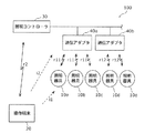
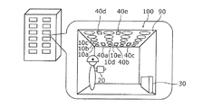
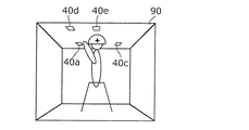
図1は、実施の形態1に係る照明システム100であって、照明システム100が備える照明器具、照明コントローラ30、通信アダプタおよび操作端末20を示す概略図である。図2は、照明器具、照明コントローラ30、通信アダプタおよび操作端末の配置の一例を示す図である。
(Embodiment 1)
[1-1. Outline configuration of lighting system]
FIG. 1 is a schematic view of the
照明システム100は、複数の照明器具10a、10b、10c、10d、10eと、照明コントローラ30と、照明コントローラ30に接続されている複数の通信アダプタ40a、40b、40c、40d、40eと、操作端末20とを備える。図2では5台の照明器具10a〜10eが示されているが、この図は一例であり、実際は建物の天井90などに100台以上の照明器具が設置されることがある。また、図2では5台の通信アダプタ40a〜40eが示されているが、この図は一例であり、実際は1台または6台以上の通信アダプタが設置されることがある。以下、複数の照明器具10a〜10eを総称して照明器具10と呼ぶ場合があり、複数の通信アダプタ40a〜40eを総称して通信アダプタ40と呼ぶ場合がある。
The
まず、図1および図2を参照しながら、照明システム100を構成する複数の照明器具10、照明コントローラ30、複数の通信アダプタ40および操作端末20の通信系統について説明する。
First, the communication systems of the plurality of
照明器具10a、10b、10cと照明コントローラ30とは、通信アダプタ40aを介して無線r11で通信可能となっている。照明器具10d、10eと照明コントローラ30とは、通信アダプタ40bを介して無線r12で通信可能となっている。無線r11およびr12による通信方式としては、920MHz帯または2.4GHz帯の周波数を利用した特定小電力無線、Zigbee(登録商標)、Bluetooth(登録商標)、または、WiFi(登録商標)などの方式が用いられる。なお、各照明器具10と、各照明器具10に対応する各通信アダプタ40とが有線ネットワークを形成し、互いに通信可能であってもよい。
The
各照明器具10と、操作端末20とは、赤外線通信i1により通信可能となっている。具体的には、操作端末20は、指向性を有する無線通信の一例である赤外線通信i1を用いて照明器具10のそれぞれに信号を送信する。各照明器具10は、操作端末20からの赤外線信号を個別に受信することができるように、例えば、5mほど間隔をあけて天井90に設置されている。例えば、照明器具10aの近くに操作端末20を位置させ、照明器具10aに向けて赤外線信号を送ることで、対象とする照明器具10aのみに情報を伝達することができる。
Each
各通信アダプタ40と、操作端末20とは、赤外線通信i2により通信可能となっている。具体的には、操作端末20は、赤外線通信i2を用いて通信アダプタ40のそれぞれに信号を送信する。各通信アダプタ40は、操作端末20からの赤外線信号を個別に受信することができるように、例えば、10m以上の間隔をあけて天井90に設置されている。例えば、通信アダプタ40aの近くに操作端末20を位置させ、通信アダプタ40aに向けて赤外線信号を送ることで、対象とする通信アダプタ40aのみに情報を伝達することができる。
Each communication adapter 40 and the
照明コントローラ30と操作端末20とは、無線r2によって通信可能となっている。無線r2による通信方式としては、無線r11と同様の方式が用いられる。なお、操作端末20と照明コントローラ30は、USBなどの接続端子により有線で通信できるようになっていてもよい。
The
照明システム100では、これらの通信系統を用いて、照明器具10と通信アダプタ40とのペアリングが行われる。
In the
[1−2.照明システムの各構成]
次に、照明システム100を構成する複数の照明器具10、操作端末20、照明コントローラ30および複数の通信アダプタ40について説明する。なお、複数の照明器具のうち照明器具10aを代表例に挙げて説明する場合があり、複数の通信アダプタ40のうち通信アダプタ40aを代表例に挙げて説明する場合がある。
[1-2. Each configuration of the lighting system]
Next, a plurality of
図3Aは、照明コントローラ30および通信アダプタ40aの制御構成を示すブロック図である。図3Bは、照明器具10aの制御構成を示すブロック図である。図3Cは、操作端末20の制御構成を示すブロック図である。図4は、操作端末20を示す概略図である。
FIG. 3A is a block diagram showing a control configuration of the
図3Bに示されるように、照明器具10aは、制御部15と、制御部15に接続されている記憶部16、光源17、通信部11および赤外線通信部12とを備えている。照明器具10aは、例えば、LEDライトである。
As shown in FIG. 3B, the
通信部11は、例えばアンテナおよび無線モジュールなどであり、通信アダプタ40aを介して照明コントローラ30と通信する。
The
光源17は、例えば、白色光、赤色光、緑色光または青色光を発する複数の発光ダイオードを含んでいる。
The
赤外線通信部12は、例えば、赤外線センサであり、操作端末20から赤外線通信i1で送信された情報を受信する。本実施の形態では、照明器具10aには、ペアリング相手である通信アダプタ40aの識別情報が送信される。ただし、通信アダプタ40aが不具合を有する場合は、正規の識別情報とは異なる仮の識別情報が送信される。
The
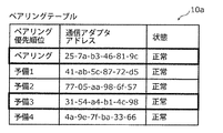
記憶部16は、RAM(Random Access Memory)およびROM(read only memory)などによって構成されている。記憶部16には、照明器具10のMACアドレス(Media Access Control address)またはUDID(Unique Device IDentifier)などの識別情報が保存されている。また、記憶部16には、操作端末20から送信された通信アダプタ40aの識別情報が書き込まれる。ただし、通信アダプタ40aが不具合を有する場合は、記憶部16には、仮の識別情報が書き込まれる。また、ペアリング終了時には、記憶部16に、複数の通信アダプタ40のうちのどの通信アダプタ40と優先的にペアリングを行うかを示すペアリングテーブルが保存される(図17B参照)。
The
制御部15は、CPU(central processing unit)などによって構成されている。制御部15は、光源17を調光制御および/または調色制御する。また、制御部15は、通信アダプタ40aとペアリングを行う際、記憶部16から自身の識別情報を読み出し、通信部11を介して、自身の識別情報を通信アダプタ40aに送信する。
The
図3Aに示されるように、照明コントローラ30は、制御部35と、制御部35に接続されている記憶部36および通信部31とを備えている。照明コントローラ30は、各照明器具10の点灯制御を行う管理サーバである。
As shown in FIG. 3A, the
通信部31は、前述したように、操作端末20と無線r2で通信する。
As described above, the
記憶部36はRAMおよびROMなどによって構成されている。記憶部36には、アドレステーブルが保存される。ペアリング終了時のアドレステーブルには、通信アダプタ40の番号、正規の識別情報(例えばMACアドレス)および仮の識別情報などが含まれている(図17A参照)。
The
制御部35は、CPUによって構成されている。制御部35は、ペアリング終了時のアドレステーブルに基づいて各照明器具10の点灯を制御する。
The
図3Aに示されるように、通信アダプタ40aは、照明コントローラ30の制御部35に接続され、かつ、照明コントローラ30の外部に配置されている。通信アダプタ40aは、制御部45と、制御部45に接続されている記憶部46、通信部41、赤外線通信部42およびランプ47とを備えている。
As shown in FIG. 3A, the
通信部41は、例えばアンテナおよび無線モジュールであり、照明コントローラ30と照明器具10aとを無線r11で接続する。
The
ランプ47は、通信アダプタ40aが正常か否かを報知するためのパイロットランプである。例えば、通信アダプタ40aと照明コントローラ30との通信が成立しなかった場合、ランプ47が点滅する。
The
記憶部46は、RAMおよびROMなどによって構成されている。記憶部46には、通信アダプタ40のMACアドレスまたはUDIDなどの識別情報が保存されている。制御部45は、CPUなどによって構成されている。
The
赤外線通信部42は、例えば、赤外線センサであり、操作端末20から赤外線通信i2で送信された情報または指令を受信する。通信アダプタ40aは、操作端末20から、通信アダプタ40aの識別情報を回答するように指令を受けると、自身の識別情報を操作端末20に送信する。
The
図3Cに示されるように、操作端末20は、制御部25と、制御部25に接続されている記憶部26、赤外線通信部22、タッチパネル23および通信部21とを備えている。操作端末20は、例えば、タブレット端末やスマートフォンである。本実施の形態における操作端末20は、照明器具10と通信アダプタ40とのペアリングを行うための設定器として用いられる。
As shown in FIG. 3C, the
通信部21は、アンテナおよび無線モジュールなどにより構成されている。通信部21は、無線r2を用いて照明コントローラ30と通信可能になっている。
The
赤外線通信部22は、例えば、赤外線LEDなどの発信器であり、赤外線通信i1を用いて各照明器具10に対応する通信アダプタ40の識別情報を送信する。また、赤外線通信部22は、赤外線通信i2を用いて各通信アダプタ40に、各通信アダプタ40の識別情報を回答するように指令を出す。
The
記憶部26は、RAMおよびROMなどにより構成されている。記憶部26には、建物内に配置されている各照明器具10、各通信アダプタ40のレイアウト情報が記憶されている。また、記憶部26にはアドレステーブルが保存される。ペアリング終了時のアドレステーブルには、通信アダプタ40の番号、正規の識別情報および仮の識別情報などが含まれている(図17A参照)。このアドレステーブルは、照明コントローラ30と操作端末20とで共有される。
The
制御部25は、CPUによって構成されている。制御部25は、記憶部26、赤外線通信部22、タッチパネル23および通信部21の作動を制御する。
The
タッチパネル23は、建物内における各照明器具10および各通信アダプタ40の配置を表示する。また、タッチパネル23は、ペアリングを行う際に必要な操作の受け付けを行う。ユーザがタッチパネル23を操作することで、ペアリングを行うための各種操作が入力される。
The
[1−3.照明システムのペアリング方法]
図5〜図17Bを参照して、照明システム100のペアリング方法について具体的に説明する。図5は、照明システム100のペアリング方法を示すフローチャートである。
[1-3. Lighting system pairing method]
The pairing method of the
はじめに、照明システム100の施工業者によって、照明器具10、通信アダプタ40および照明コントローラ30が所定の位置に取り付けられ、配線された状態となっている。この状態において、本実施の形態におけるペアリングが行われる。
First, the
まず、照明システム100において、照明コントローラ30に予め決められた数の通信アダプタ40が接続されているか否かを判断する(S11)。具体的には、照明コントローラ30と通信アダプタ40との通信を試みることで、照明コントローラ30に予め決められた数の通信アダプタ40が接続されているか否かを確認する。通信アダプタ40が接続されているか否かは、例えば、通信アダプタ40が故障しており、実質的に通信アダプタ40が接続されていない場合が含まれる。また、施工時に結線されていなかったり、通信アダプタ40の数が足りなくて接続されていない場合も含まれる。
First, in the
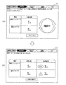
操作端末20のタッチパネル23上では、図6の(a)に示されるように、1台の照明コントローラ30と5台の通信アダプタ40の接続状態が表示される。図6の(b)では、5台のうち3台の通信アダプタの接続は確認できているが、残り2台の通信アダプタ40の接続は確認できていないことが示されている。
On the
なお、ステップS11において、予め決められた数の通信アダプタ40が接続されている場合は(S11のYes)、通常どおり、各通信アダプタ40と各照明器具10とがペアリングされ(S18)、ペアリング作業を終える。本実施の形態では、通信アダプタ40が不具合を有しており、予め決められた数の通信アダプタ40が接続されていないと判断され(S11のNo)、以下に示すステップに移行する。
In step S11, when a predetermined number of communication adapters 40 are connected (Yes in S11), each communication adapter 40 and each
まず、上記のように照明コントローラ30に接続されておらず、不具合を有する通信アダプタ40を特定する(S12)。通信アダプタ40が不具合を有すると、通信アダプタ40のランプ47が点滅する。施工業者は、図7に示されるように、施工現場にて不具合を有する通信アダプタ40を目視で確認する。本実施の形態では、5台の通信アダプタ40のうち通信アダプタ40aおよび40dが接続されておらず、不具合を有している。以下、照明コントローラ30に接続されていない通信アダプタ40a、40dを、不具合を有する通信アダプタ40a、40dと呼び、照明コントローラ30に接続されている通信アダプタ40b、40c、40eを正常な通信アダプタ40b、40c、40eと呼んで説明する。
First, the communication adapter 40 that is not connected to the
タッチパネル23上では、図8の(a)に示されるように、不具合を有する通信アダプタ40がタッチパネル23にてタッチされることで選択される。本実施の形態では、通信アダプタ40a、40dに対応する番号1、4が選択される。すると、図8の(b)に示されるように、選択された番号が反転表示され、不具合を有する通信アダプタ40a、40dが特定される。
On the
次に、不具合を有する通信アダプタ40a、40dの仮の識別情報を生成する(S13)。上記のように通信アダプタ40a、40dが不具合を有する場合は、照明システム100としては、通信アダプタ40a、40dの識別情報が不明である。そこで、不具合を有する通信アダプタ40a、40dに対応する仮の識別情報を生成する。仮の識別情報とは、例えば、不具合を有する通信アダプタ40a、40dについて、ペアリングを行うために一時的に設定する仮のアドレスである。
Next, temporary identification information of the
タッチパネル23上では、図8の(b)に示されるように、不具合を有する通信アダプタ40a、40dに対応する仮のアドレスを発行して、ペアリング作業を続行するか否かが表示される。タッチパネル23の「仮のアドレス発行」キーが押下されると、不具合を有する通信アダプタ40a、40dに対応する仮の識別情報が生成される。仮の識別番号は、例えば、「11−11−11−11−11−11」という同じ数字からなる(図11参照)。仮の識別情報は、照明コントローラ30にて生成され、記憶部36に記憶される。生成された仮の識別情報は、操作端末20と照明コントローラ30とが相互通信することで、操作端末20の記憶部26に記憶される。なお、仮の識別情報は、操作端末20にて生成されてもよい。操作端末20に記憶された仮の識別情報は、タッチパネル23に表示可能である。
On the
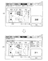
次に、正常な通信アダプタ40b、40c、40eの識別情報を取得する(S14)。取得する識別情報は、例えば、通信アダプタ40b、40c、40eのMACアドレスである。識別情報の取得は、図9に示されるように、操作端末20から各通信アダプタ40b、40c、40eに送る赤外線信号をきっかけとして実行される。例えば、操作端末20から通信アダプタ40bに対して、通信アダプタ40bの識別情報を回答させるための指令が送られ、その指令を受けた通信アダプタ40bは、自身の識別情報を操作端末20に送信する。送信ルートとしては、例えば、照明コントローラ30を介して操作端末20に識別情報が送信されてもよいし、通信アダプタ40bと操作端末20とで共有する無線通信が確立されていれば、その無線通信を用いて上記識別情報が送信されてもよい。
Next, the identification information of the
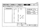
タッチパネル23上では、図10の(a)に示されるように、操作端末20を通信アダプタ40bの方に向けて、送信ボタンを押す指示が表示される。例えば、通信対象である通信アダプタ40bが、四角の太枠で囲まれて表示される。タッチパネル23の「送信」キーが押下されると、上記の赤外線信号が送信される。操作端末20が通信アダプタ40bの識別情報を取得すると、タッチパネル23上では、図10の(b)に示されるように、識別情報を問題なく取得したことが表示される。例えば、設定完了した通信アダプタ40bが、丸の太枠で囲まれて表示される。取得した識別情報は、記憶部26に記憶され、タッチパネル23に表示可能である。この識別情報の取得、記憶および表示は、通信アダプタ40c、40eについても同様に行われる。
On the
次に、取得した識別情報および生成した仮の識別情報を操作端末20に記憶する(S15)。すでに、ステップS13において不具合を有する通信アダプタ40a、40dに対応する仮の識別情報が生成され、また、ステップS14において正常な通信アダプタ40b、40c、40eの識別情報が取得されているので、図11に示されるようなアドレステーブルが作成される。このアドレステーブルは、ステップS13およびステップS14が実行されることで、照明コントローラ30および操作端末20の両方に保存される。操作端末20に保存されたアドレステーブルは、タッチパネル23に表示可能である。なお、不具合を有する通信アダプタ40a、40dに対応する識別情報は、仮アドレスの状態となっている。
Next, the acquired identification information and the generated temporary identification information are stored in the operation terminal 20 (S15). Since the temporary identification information corresponding to the
次に、操作端末20を用いて各照明器具10に、取得した識別情報または生成した仮の識別情報を記憶する(S16)。例えば、正常な通信アダプタ40bに対応する照明器具10d、10eには、ステップS14にて取得した正規の識別情報が記憶される。不具合を有する通信アダプタ40aに対応する照明器具10a、10b、10cには、ステップS13にて生成された仮の識別情報が記憶される。
Next, the
具体的には、図12に示されるように、操作端末20を各照明器具10に向け、赤外線通信i1で、それぞれに対応する識別情報を送信する。これにより、各照明器具10に対応する識別情報を記憶する。タッチパネル23上では、図13の(a)に示されるように、操作端末20を各照明器具10の方に向けて送信ボタンを押す指示が表示される。例えば、通信対象である番号1の照明器具10(図13の(a)参照)が、四角の太枠で囲まれて表示される。タッチパネル23の「送信」キーが押下されると、操作端末20から照明器具10に対して赤外線信号が送られ、各照明器具10に対応する識別情報が書き込まれる。
Specifically, as shown in FIG. 12, the
次に、正常な通信アダプタ40と、それに対応する照明器具10とをペアリングする(S17)。本実施の形態では、不具合を有する通信アダプタ40aよりも先に、正常な通信アダプタ40bと各照明器具10d、10eとをペアリングする。タッチパネル23上では、図13の(b)に示されるように、ペアリングが正常に設定できたことが表示される。例えば、設定完了した番号1の照明器具10が、丸の太枠で囲まれて表示される。通信アダプタ40bとのペアリングが成立した照明器具10d、10eは、明るさが低下する。明るさが低下することで、ユーザが、通信アダプタ40bと照明器具10d、10eとでペアリングが成立していることを視認することができる。
Next, the normal communication adapter 40 and the
なお、実際のペアリングは終了していないが、照明器具10aの記憶部16には、図14に示されるように、通信アダプタ40のペアリング優先順位が記憶される。この時点で、照明器具10aのペアリング先は、通信アダプタ40aに対応する仮の識別情報が第1優先として記載されている。
Although the actual pairing has not been completed, the pairing priority of the communication adapter 40 is stored in the
これらのステップS11〜S17によって、正常な通信アダプタ40と照明器具10とのペアリングを一旦終える。
By these steps S11 to S17, the pairing between the normal communication adapter 40 and the
次に、不具合を有する通信アダプタ40とは異なる新たな通信アダプタ40を入荷し、新たな通信アダプタ40に交換する(S21)。具体的には、図15に示されるように、不具合を有する通信アダプタ40a、40dの代わりに、それぞれに対応させて新たな通信アダプタ40a、40dを設置する。新たな通信アダプタ40a、40dは、不具合を有していない。
Next, a new communication adapter 40 different from the defective communication adapter 40 is received and replaced with a new communication adapter 40 (S21). Specifically, as shown in FIG. 15,
次に、交換した新たな通信アダプタ40a、40dの識別情報を取得する(S22)。新たな通信アダプタ40a、40dを照明コントローラ30に接続することによって、照明コントローラ30は、新たな通信アダプタ40a、40dを認識し、各通信アダプタ40a、40dから正規の識別情報を取得する。取得した正規の識別情報は、タッチパネル23に表示可能である。
Next, the identification information of the new exchanged
次に、新たな通信アダプタ40の識別情報と仮の識別情報とを関連付けた状態で照明器具10に入力する(S23)。例えば、ステップS22で取得した新たな通信アダプタ40aの識別情報と、ステップS13で生成した仮の識別情報とを関連付けた状態で照明器具10aに入力する。この入力によって、照明器具10aに記憶されていた仮の識別情報は、新たな通信アダプタ40aが有する正規の識別情報に書き換えられる。これらの識別情報の書き換えは、例えば、照明コントローラ30から新たな通信アダプタ40aを介して、照明器具10a、10b、10cに対して同時に書き換えられる。新たな通信アダプタ40の識別情報と仮の識別情報とが関連付けられた状態で照明器具10に入力されるので、このような同時の書き換えが可能となっている。
Next, the identification information of the new communication adapter 40 and the provisional identification information are input to the
タッチパネル23上では、図16に示されるように、照明コントローラ30にて新しい通信アダプタ40が認識されることで、通信アダプタ40のアドレスを更新するか否かが表示される。タッチパネル23の「アドレス更新」キーが押下されると、上記に示すように仮の識別情報が正規の識別情報に書き換えられる。
On the
次に、新たな通信アダプタ40と照明器具10とをペアリングする(S24)。本実施の形態では、新たな通信アダプタ40aと各照明器具10a、10b、10cとをそれぞれペアリングする。通信アダプタ40aとのペアリングが成立した照明器具10a、10b、10cは、明るさが低下する。明るさが低下することで、ユーザが、通信アダプタ40aと照明器具10a、10b、10cとでペアリングが成立していることを視認することができる。
Next, the new communication adapter 40 and the
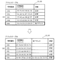
操作端末20および照明コントローラ30には、図17Aに示されるアドレステーブルが記憶される。例えば、通信アダプタ40aについては、仮の識別情報と正規の識別情報とが関連付けられた状態で、仮の識別情報が正規の識別情報に書き換えられる。
The address table shown in FIG. 17A is stored in the
また、照明器具10aの記憶部16には、図17Bに示されるペアリングテーブルが記憶される。例えば、ペアリング優先順位の中に記入されていた仮の識別情報が正規の識別情報に書き換えられる。
Further, the pairing table shown in FIG. 17B is stored in the
ペアリング終了後のアドレステーブルおよびペアリングテーブルは、タッチパネル23に表示可能である。
The address table and the pairing table after the pairing is completed can be displayed on the
以上のステップにより、照明器具10と通信アダプタ40とのペアリングが全て終了する。本実施の形態では、通信アダプタ40が不具合を有する場合であっても、ペアリング作業の一部を進めることができ、施工作業の工期が長期化することを抑制することができる。
By the above steps, all pairing between the
[1−4.効果等]
本実施の形態に係る照明システム100のペアリング方法は、複数の照明器具10と、複数の照明器具10と通信する1以上の通信アダプタ40と、通信アダプタ40を介して複数の照明器具10の点灯を制御する照明コントローラ30と、複数の照明器具10および照明コントローラ30と通信する操作端末20とを備える照明システム100において、照明器具10と通信アダプタ40とのペアリングを行う、照明システム100のペアリング方法であって、照明コントローラ30に予め決められた数の通信アダプタ40が接続されておらず、接続されていない通信アダプタ40の識別情報が不明である場合に、操作端末20に、当該識別情報の代わりに仮の識別情報を記憶する工程と、仮の識別情報が記憶された操作端末20を用いて、接続されていない通信アダプタ40に対応する照明器具10に、仮の識別情報を記憶する工程と、照明器具10に仮の識別情報が記憶された後、照明コントローラ30に、接続されていない通信アダプタ40と異なる新たな通信アダプタ40が接続された場合に、新たな通信アダプタ40の識別情報を取得する工程と、新たな通信アダプタ40の識別情報と仮の識別情報とを関連付けた状態で照明器具10に入力し、当該照明器具10と新たな通信アダプタ40とをペアリングする工程とを含む。
[1-4. Effect, etc.]
The pairing method of the
これによれば、通信アダプタ40が不具合を有する場合であっても、ペアリング作業の一部を進めることができ、施工作業の工期が長期化することを抑制することができる。 According to this, even if the communication adapter 40 has a defect, a part of the pairing work can be proceeded, and it is possible to suppress the lengthening of the construction period of the construction work.
また、操作端末20に仮の識別情報を記憶する工程の前に、照明コントローラ30と通信アダプタ40との通信を試みることで、照明コントローラ30に予め決められた数の通信アダプタ40が接続されているか否かを確認する確認工程を含んでいてもよい。
Further, by attempting communication between the
このように、照明コントローラ30と通信アダプタ40との通信を試みることで、照明コントローラ30に通信アダプタ40が接続されているか否かを容易に確認することができる。
By attempting communication between the
また、確認工程と、操作端末20に仮の識別情報を記憶する工程との間に、仮の識別情報を照明コントローラ30または操作端末20にて生成する工程を含んでいてもよい。
Further, a step of generating temporary identification information by the
このように、仮の識別情報を生成することで、通信アダプタ40が不具合を有する場合であっても、ペアリング作業の一部を進めることができ、施工作業の工期が長期化することを抑制することができる。 By generating the temporary identification information in this way, even if the communication adapter 40 has a defect, it is possible to proceed with a part of the pairing work and suppress the lengthening of the construction work period. can do.
また、操作端末20に仮の識別情報を記憶する工程において、記憶した仮の識別情報を操作端末20のタッチパネル23に表示し、新たな通信アダプタ40の識別情報を取得する工程において、仮の識別情報に代えてまたは仮の識別情報に対応させて、取得した識別情報をタッチパネル23に表示してもよい。
Further, in the step of storing the temporary identification information in the
これによれば、ユーザが、仮の識別情報が付与されている通信アダプタ40を目で確認し、また、正規の識別情報が付与されている新たな通信アダプタ40を目で確認することができるので、ペアリングの作業性を向上することができる。 According to this, the user can visually confirm the communication adapter 40 to which the temporary identification information is given, and can visually confirm the new communication adapter 40 to which the regular identification information is given. Therefore, the workability of pairing can be improved.
また、操作端末20に仮の識別情報を記憶する工程において、接続されていない通信アダプタ40が複数ある場合に、複数の通信アダプタ40のそれぞれに対応して、複数の異なる仮の識別情報を操作端末20に記憶してもよい。
Further, in the process of storing the temporary identification information in the
このように、複数の仮の識別情報を生成することで、複数の通信アダプタ40が不具合を有する場合であっても、ペアリング作業の一部を進めることができ、施工作業の工期が長期化することを抑制することができる。 By generating a plurality of temporary identification information in this way, even if the plurality of communication adapters 40 have a defect, a part of the pairing work can be advanced, and the construction period of the construction work is prolonged. It can be suppressed.
本実施の形態に係る照明コントローラ30は、通信アダプタ40を介して複数の照明器具10の点灯を制御する照明コントローラ30であって、通信アダプタ40が不具合を有する場合に、不具合を有する通信アダプタ40に対応する仮の識別情報を記憶し、不具合を有する通信アダプタ40が、不具合を有する通信アダプタ40と異なる新たな通信アダプタ40に取り替えられた場合に、新たな通信アダプタ40から識別情報を取得し、記憶している仮の識別情報を、新たな通信アダプタ40の識別情報に置き換える。
The
この照明コントローラ30によれば、通信アダプタ40が不具合を有する場合であっても、ペアリング作業の一部を進めることができ、施工作業の工期が長期化することを抑制することができる。
According to the
(実施の形態2)
実施の形態2は、通信アダプタ40などの機材の不具合でなく、施工業者が初期対応事項によって問題を解決する形態である。図18は、実施の形態2において不具合時の初期対応事項を示す図である。
(Embodiment 2)
The second embodiment is not a defect of the equipment such as the communication adapter 40, but a form in which the contractor solves the problem by the initial measures. FIG. 18 is a diagram showing initial countermeasures at the time of failure in the second embodiment.
まず、実施の形態1と同様に、照明コントローラ30に予め決められた数の通信アダプタ40が接続されているか否かを判断する(S11)。具体的には、照明コントローラ30と通信アダプタ40との通信を試みることで、照明コントローラ30に予め決められた数の通信アダプタ40が接続されているか否かを確認する。
First, as in the first embodiment, it is determined whether or not a predetermined number of communication adapters 40 are connected to the lighting controller 30 (S11). Specifically, by attempting communication between the
そして、予め決められた数の通信アダプタ40が接続されていないと判断された場合に(S11のNo)、以下に示すステップが実行される。 Then, when it is determined that a predetermined number of communication adapters 40 are not connected (No in S11), the following steps are executed.
操作端末20のタッチパネル23では、図18の(a)に示されるように、異常モードを特定するための画面が表示される。異常モードとしては、「未施工」、「ランプ不点灯」、「ランプ赤点灯」の3つのモードが表示される。この中から、通信アダプタ40の現在の状態が選択されると、図18の(b)〜(d)に示されるように、それぞれの初期対応事項が表示される。
On the
「未施工」状態への対処としては、図18の(b)に示されるように、通信アダプタ40の施工を行うことを指示する画面が表示される。「ランプ不点灯」状態への対処としては、図18の(c)に示されるように、電源線が正しく施工されているか確認することを指示する画面が表示される。「ランプ赤点灯」状態への対処としては、図18の(d)に示されるように、電源線、通信線が正しく施工されているか確認することを指示する画面が表示される。そして、施工業者にてこれらの問題が解決されると、タッチパネル23上にて初期対応事項が対応済みであることが入力され、初期対応事項が終了する。
As a countermeasure for the "unconstructed" state, as shown in FIG. 18B, a screen instructing the construction of the communication adapter 40 is displayed. As a countermeasure for the "lamp not lit" state, as shown in FIG. 18C, a screen instructing to confirm whether the power line is installed correctly is displayed. As a countermeasure to the "lamp red lighting" state, as shown in FIG. 18D, a screen instructing to confirm whether the power line and the communication line are correctly constructed is displayed. Then, when the contractor solves these problems, it is input on the
実施の形態2では、照明コントローラ30に予め決められた数の通信アダプタ40が接続されているか否かを確認する確認工程において、照明コントローラ30と通信アダプタ40との通信が成立しない場合に、通信アダプタ40を照明コントローラ30に接続するための初期対応事項を操作端末20のタッチパネル23に表示し、操作端末20に初期対応事項が対応済みであることが入力された場合に、上記確認工程を終了する。
In the second embodiment, in the confirmation step of confirming whether or not a predetermined number of communication adapters 40 are connected to the
これによれば、施工業者で解決可能な不具合であることを、施工業者が知り、自身で解決することができる。そのため、施工作業の工期が長期化することを抑制することができる。 According to this, the contractor knows that the problem can be solved by the contractor and can solve it by himself / herself. Therefore, it is possible to prevent the construction period from being prolonged.
(実施の形態3)
実施の形態3は、照明器具10が不具合を有する場合に、照明システム100においてペアリングを行う形態である。本実施の形態では、複数の照明器具10のうち、照明器具10eが不具合を有する照明器具であるとして説明する。
(Embodiment 3)
The third embodiment is a mode in which pairing is performed in the
図19は、実施の形態3における照明システム100のペアリング方法を示すフローチャートである。なお、図19では、不具合を有する照明器具10eに関係するステップが示されている。
FIG. 19 is a flowchart showing a pairing method of the
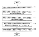
まず、不具合を有する照明器具10の仮の識別情報を生成する(S31)。上記のように照明器具10eが不具合を有する場合は、照明システム100としては、照明器具10の識別情報が不明である。そこで、不具合を有する照明器具10eに対応する仮の識別情報を生成する。仮の識別情報とは、例えば、不具合を有する照明器具10について、ペアリングを行うために一時的に設定する仮のアドレスである。
First, temporary identification information of the
タッチパネル23上では、図20に示されるように、不具合を有する照明器具10eに対応する仮のアドレスを発行するか否かが表示される。タッチパネル23の「仮のアドレス発行」キーが押下されると、照明器具10eに対応する仮の識別情報が生成される。仮の識別番号は、例えば、「55−55−55−55−55−55」という同じ数字からなる(図21の(a)参照)。仮の識別情報は、照明コントローラ30にて生成され、記憶部36に記憶される。生成された仮の識別情報は、操作端末20と照明コントローラ30とが相互通信することで、操作端末20の記憶部26に記憶される。なお、仮の識別情報は、操作端末20にて生成されてもよい。
On the
次に、不具合を有する照明器具10に対応する通信アダプタ40に、仮の識別情報を記憶する(S32)。具体的には、操作端末20を用いて、不具合を有する照明器具10eに対応する通信アダプタ40bに、ステップS31にて生成された仮の識別情報を記憶する。
Next, provisional identification information is stored in the communication adapter 40 corresponding to the defective lighting fixture 10 (S32). Specifically, the
例えば、操作端末20を通信アダプタ40bに向け、赤外線通信i2で仮の識別情報を送信することで、通信アダプタ40bに仮の識別情報を記憶する。
For example, by pointing the
次に、不具合を有する照明器具10と異なる新たな照明器具10を入荷し、新たな照明器具10に交換する。そして、交換した新たな照明器具10の識別情報を取得する(S33)。新たな照明器具10eを通信アダプタ40aを介して照明コントローラ30に接続することによって、照明コントローラ30は、新たな照明器具10eを認識し、照明器具10eから正規の識別情報を取得する。
Next, a
次に、新たな照明器具10の識別情報と仮の識別情報とを関連付けた状態で通信アダプタ40に入力する(S34)。例えば、ステップS33で取得した新たな照明器具10eの識別情報と、ステップS31で生成した仮の識別情報とを関連付けた状態で通信アダプタ40bに入力する。この入力によって、通信アダプタ40bに記憶されていた仮の識別情報は、新たな照明器具10eが有する正規の識別情報に書き換えられる。これらの識別情報の書き換えは、例えば、以下に示すいずれかの方法にて行われる。
Next, the identification information of the
1つめの方法としては、まず、操作端末20と照明器具10とが赤外線通信i1することで、操作端末20が、照明器具10の識別情報を取得し、取得した識別情報を照明コントローラ30へ送信する。そして、この識別情報を、照明コントローラ30が通信アダプタ40に送信する。2つめの方法としては、操作端末20と照明器具10とが赤外線通信i1することで、操作端末20から照明器具10にペアリング先の通信アダプタ40の識別情報を通知する。次に、照明器具10が通信アダプタ40に対して識別情報の書き換え指示を行い、通信アダプタ40が自身の識別情報を書き換える。そして、通信アダプタ40が照明コントローラ30に対して識別情報の書き換え終了を通知する。
As the first method, first, the
なお、上記では、1台の照明器具10eに対応する通信アダプタ40bにおいて識別情報を書き換える例について説明したが、不具合を有する照明器具10が複数台ある場合は、複数台の照明器具10に対応する通信アダプタ40において、識別情報が同時に書き換えられる。新たな照明器具10の識別情報と仮の識別情報とが関連付けられた状態で通信アダプタ40に入力されるので、このような同時の書き換えが可能である。
In the above, an example of rewriting the identification information in the
次に、新たな照明器具10と通信アダプタ40とをペアリングする(S35)。本実施の形態では、新たな照明器具10eと通信アダプタ40bとをペアリングする。通信アダプタ40bとのペアリングが成立した照明器具10eは、明るさが低下する。
Next, the
操作端末20および照明コントローラ30には、図21の(b)に示される照明器具10のアドレステーブルが記憶される。例えば、照明器具10eについては、仮の識別情報が、新たな照明器具10eの識別情報に書き換えられている。
The
以上のステップにより、不具合を有する照明器具10と通信アダプタ40とのペアリングが終了する。本実施の形態では、照明器具10が不具合を有する場合であっても、ペアリング作業の一部を進めることができ、施工作業の工期が長期化することを抑制することができる。
By the above steps, the pairing of the
実施の形態3に係る照明システム100のペアリング方法は、複数の照明器具10と、複数の照明器具10と通信する1以上の通信アダプタ40と、通信アダプタ40を介して複数の照明器具10の点灯を制御する照明コントローラ30と、複数の照明器具10および照明コントローラ30と通信する操作端末20とを備える照明システム100において、照明器具10と通信アダプタ40とのペアリングを行う、照明システム100のペアリング方法であって、照明器具10が不具合を有し照明器具10の識別情報が不明である場合に、操作端末20に、上記識別情報の代わりに仮の識別情報を記憶する工程と、不具合を有する照明器具10に対応する通信アダプタ40に、仮の識別情報を記憶する工程と、通信アダプタ40に仮の識別情報が記憶された後、不具合を有する照明器具10に代えて新たな照明器具10が取り付けられた場合に、新たな照明器具10の識別情報を取得する工程と、新たな照明器具10の識別情報と仮の識別情報とを関連付けた状態で通信アダプタ40に入力し、新たな照明器具10と通信アダプタ40とをペアリングする工程とを含む。
The pairing method of the
これによれば、照明器具10が不具合を有する場合であっても、ペアリング作業の一部を進めることができ、施工作業の工期が長期化することを抑制することができる。
According to this, even if the
実施の形態3に係る照明コントローラ30は、通信アダプタ40を介して複数の照明器具10の点灯を制御する照明コントローラ30であって、照明器具10が不具合を有する場合に、不具合を有する照明器具10に対応する仮の識別情報を記憶し、不具合を有する照明器具10が、不具合を有する照明器具10と異なる新たな照明器具10に取り替えられた場合に、新たな照明器具10から識別情報を取得し、記憶している仮の識別情報を、新たな照明器具10の識別情報に置き換える。
The
この照明コントローラ30によれば、照明器具10が不具合を有する場合であっても、ペアリング作業の一部を進めることができ、施工作業の工期が長期化することを抑制することができる。
According to the
(その他の形態)
以上、照明システム100のペアリング方法等について、実施の形態に基づいて説明したが、本発明は、上記の実施の形態に限定されるものではない。例えば、上記の実施の形態に対して当業者が思いつく各種変形を施して得られる形態や、本発明の趣旨を逸脱しない範囲で実施の形態における構成要素および機能を任意に組み合わせることで実現される形態も本発明に含まれる。
(Other forms)
The pairing method and the like of the
例えば、実施の形態1では、不具合を有する通信アダプタ40として2台の通信アダプタ40を例示したが、不具合を有する通信アダプタ40は1台であってもよい。また、不具合を有する通信アダプタ40は全台であってもよい。すなわち、本実施の形態は、仮の識別情報を用いてペアリング作業の一部を進め、新たな通信アダプタ40を接続した場合に、仮の識別情報と新たな通信アダプタ40の識別情報とを関連付けた状態で、照明器具10に入力するような態様であればよい。
For example, in the first embodiment, two communication adapters 40 are exemplified as the defective communication adapter 40, but the defective communication adapter 40 may be one. Further, the number of defective communication adapters 40 may be all. That is, in the present embodiment, when a part of the pairing work is advanced using the temporary identification information and a new communication adapter 40 is connected, the temporary identification information and the identification information of the new communication adapter 40 are obtained. Any mode may be used as long as it is input to the
また、実施の形態1では、操作端末20から赤外線通信i1、i2を発信している例を示したが、それに限られない。例えば、赤外線通信i1、i2の代わりに、レーザ光またはNFC(Near Field Communication)など1対1で対応をとることが可能な無線を用いて、照明器具10または通信アダプタ40に対して個別に信号を送信してもよい。
Further, in the first embodiment, an example in which infrared communication i1 and i2 are transmitted from the
10、10a、10b、10c、10d、10e 照明器具
20 操作端末
23 タッチパネル
30 照明コントローラ
40、40a、40b、40c、40d、40e 通信アダプタ
100 照明システム
10, 10a, 10b, 10c, 10d,
Claims (9)
前記複数の照明器具と通信する1以上の通信アダプタと、
前記通信アダプタを介して前記複数の照明器具の点灯を制御する照明コントローラと、
前記複数の照明器具および前記照明コントローラと通信する操作端末と
を備える照明システムにおいて、前記照明器具と前記通信アダプタとのペアリングを行う、照明システムのペアリング方法であって、
前記照明コントローラに予め決められた数の前記通信アダプタが接続されておらず、接続されていない通信アダプタの識別情報が不明である場合に、前記操作端末に、当該識別情報の代わりに仮の識別情報を記憶する工程と、
前記仮の識別情報が記憶された前記操作端末を用いて、前記接続されていない通信アダプタに対応する前記照明器具に、前記仮の識別情報を記憶する工程と、
前記照明器具に前記仮の識別情報が記憶された後、前記照明コントローラに、前記接続されていない通信アダプタと異なる新たな通信アダプタが接続された場合に、前記新たな通信アダプタの識別情報を取得する工程と、
前記新たな通信アダプタの識別情報と前記仮の識別情報とを関連付けた状態で前記照明器具に入力し、当該照明器具と前記新たな通信アダプタとをペアリングする工程と
を含む照明システムのペアリング方法。 With multiple lighting fixtures
One or more communication adapters that communicate with the plurality of lighting fixtures,
A lighting controller that controls lighting of the plurality of lighting fixtures via the communication adapter, and
A pairing method for a lighting system in which the lighting fixture and the communication adapter are paired in a lighting system including the plurality of lighting fixtures and an operation terminal that communicates with the lighting controller.
When a predetermined number of the communication adapters are not connected to the lighting controller and the identification information of the unconnected communication adapters is unknown, the operation terminal is temporarily identified instead of the identification information. The process of storing information and
A step of storing the temporary identification information in the lighting equipment corresponding to the unconnected communication adapter by using the operation terminal in which the temporary identification information is stored.
After the temporary identification information is stored in the lighting fixture, when a new communication adapter different from the unconnected communication adapter is connected to the lighting controller, the identification information of the new communication adapter is acquired. And the process to do
Pairing of a lighting system including a step of inputting the identification information of the new communication adapter and the temporary identification information into the luminaire and pairing the luminaire with the new communication adapter. Method.
前記照明コントローラと前記通信アダプタとの通信を試みることで、前記照明コントローラに予め決められた数の前記通信アダプタが接続されているか否かを確認する確認工程を含む
請求項1に記載の照明システムのペアリング方法。 Before the step of storing the temporary identification information in the operation terminal,
The lighting system according to claim 1, further comprising a confirmation step of confirming whether or not a predetermined number of the communication adapters are connected to the lighting controller by attempting communication between the lighting controller and the communication adapter. Pairing method.
請求項2に記載の照明システムのペアリング方法。 In the confirmation step, when communication between the lighting controller and the communication adapter is not established, initial measures for connecting the communication adapter to the lighting controller are displayed on the touch panel of the operation terminal, and the operation terminal is displayed. The pairing method for a lighting system according to claim 2, wherein the confirmation step is terminated when it is input that the initial correspondence items have been dealt with.
請求項2または3に記載の照明システムのペアリング方法。 The second or third claim includes a step of generating the temporary identification information by the lighting controller or the operation terminal between the confirmation step and the step of storing the temporary identification information in the operation terminal. How to pair your lighting system.
前記新たな通信アダプタの識別情報を取得する工程において、前記仮の識別情報に代えてまたは前記仮の識別情報に対応させて、取得した前記識別情報を前記タッチパネルに表示する
請求項1〜4のいずれか1項に記載の照明システムのペアリング方法。 In the step of storing the temporary identification information in the operation terminal, the stored temporary identification information is displayed on the touch panel of the operation terminal.
Claims 1 to 4 in which the acquired identification information is displayed on the touch panel in place of the provisional identification information or in correspondence with the provisional identification information in the step of acquiring the identification information of the new communication adapter. The pairing method for the lighting system according to any one of the items.
前記接続されていない通信アダプタが複数ある場合に、複数の前記通信アダプタのそれぞれに対応して、複数の異なる前記仮の識別情報を前記操作端末に記憶する
請求項1〜5のいずれか1項に記載の照明システムのペアリング方法。 In the step of storing the temporary identification information in the operation terminal,
Any one of claims 1 to 5 for storing a plurality of different provisional identification information in the operation terminal corresponding to each of the plurality of communication adapters when there are a plurality of unconnected communication adapters. The pairing method of the lighting system described in.
前記複数の照明器具と通信する1以上の通信アダプタと、
前記通信アダプタを介して前記複数の照明器具の点灯を制御する照明コントローラと、
前記複数の照明器具および前記照明コントローラと通信する操作端末と
を備える照明システムにおいて、前記照明器具と前記通信アダプタとのペアリングを行う、照明システムのペアリング方法であって、
前記照明器具が不具合を有し前記照明器具の識別情報が不明である場合に、前記操作端末に、前記識別情報の代わりに仮の識別情報を記憶する工程と、
前記不具合を有する照明器具に対応する前記通信アダプタに、前記仮の識別情報を記憶する工程と、
前記通信アダプタに前記仮の識別情報が記憶された後、前記不具合を有する照明器具に代えて新たな照明器具が取り付けられた場合に、前記新たな照明器具の識別情報を取得する工程と、
前記新たな照明器具の識別情報と前記仮の識別情報とを関連付けた状態で前記通信アダプタに入力し、前記新たな照明器具と前記通信アダプタとをペアリングする工程と
を含む照明システムのペアリング方法。 With multiple lighting fixtures
One or more communication adapters that communicate with the plurality of lighting fixtures,
A lighting controller that controls lighting of the plurality of lighting fixtures via the communication adapter, and
A pairing method for a lighting system in which the lighting fixture and the communication adapter are paired in a lighting system including the plurality of lighting fixtures and an operation terminal that communicates with the lighting controller.
A step of storing temporary identification information in place of the identification information in the operation terminal when the lighting equipment has a defect and the identification information of the lighting equipment is unknown.
A step of storing the temporary identification information in the communication adapter corresponding to the lighting fixture having the defect, and
A step of acquiring the identification information of the new luminaire when a new luminaire is attached in place of the luminaire having the defect after the temporary identification information is stored in the communication adapter.
Pairing of a lighting system including a step of inputting into the communication adapter in a state where the identification information of the new luminaire and the provisional identification information are associated with each other and pairing the new luminaire with the communication adapter. Method.
前記通信アダプタが不具合を有する場合に、前記不具合を有する通信アダプタに対応する仮の識別情報を記憶し、
前記不具合を有する通信アダプタが、前記不具合を有する通信アダプタと異なる新たな通信アダプタに取り替えられた場合に、前記新たな通信アダプタから識別情報を取得し、
記憶している前記仮の識別情報を、前記新たな通信アダプタの識別情報に置き換える
照明コントローラ。 A lighting controller that controls the lighting of multiple lighting fixtures via a communication adapter.
When the communication adapter has a defect, provisional identification information corresponding to the communication adapter having the defect is stored.
When the communication adapter having the defect is replaced with a new communication adapter different from the communication adapter having the defect, the identification information is acquired from the new communication adapter.
A lighting controller that replaces the stored temporary identification information with the identification information of the new communication adapter.
前記照明器具が不具合を有する場合に、前記不具合を有する照明器具に対応する仮の識別情報を記憶し、
前記不具合を有する照明器具が、前記不具合を有する照明器具と異なる新たな照明器具に取り替えられた場合に、前記新たな照明器具から識別情報を取得し、
記憶している前記仮の識別情報を、前記新たな照明器具の識別情報に置き換える
照明コントローラ。 A lighting controller that controls the lighting of multiple lighting fixtures via a communication adapter.
When the luminaire has a defect, provisional identification information corresponding to the luminaire having the defect is stored.
When the defective luminaire is replaced with a new luminaire different from the defective luminaire, identification information is acquired from the new luminaire.
A lighting controller that replaces the stored temporary identification information with the identification information of the new lighting fixture.
Priority Applications (1)
| Application Number | Priority Date | Filing Date | Title |
|---|---|---|---|
| JP2017089488A JP6830207B2 (en) | 2017-04-28 | 2017-04-28 | Lighting system pairing method and lighting controller |
Applications Claiming Priority (1)
| Application Number | Priority Date | Filing Date | Title |
|---|---|---|---|
| JP2017089488A JP6830207B2 (en) | 2017-04-28 | 2017-04-28 | Lighting system pairing method and lighting controller |
Publications (2)
| Publication Number | Publication Date |
|---|---|
| JP2018191043A JP2018191043A (en) | 2018-11-29 |
| JP6830207B2 true JP6830207B2 (en) | 2021-02-17 |
Family
ID=64480059
Family Applications (1)
| Application Number | Title | Priority Date | Filing Date |
|---|---|---|---|
| JP2017089488A Active JP6830207B2 (en) | 2017-04-28 | 2017-04-28 | Lighting system pairing method and lighting controller |
Country Status (1)
| Country | Link |
|---|---|
| JP (1) | JP6830207B2 (en) |
-
2017
- 2017-04-28 JP JP2017089488A patent/JP6830207B2/en active Active
Also Published As
| Publication number | Publication date |
|---|---|
| JP2018191043A (en) | 2018-11-29 |
Similar Documents
| Publication | Publication Date | Title |
|---|---|---|
| JP6945156B2 (en) | Lighting system control parameter input method and operation terminal | |
| JP4720716B2 (en) | Load control system | |
| KR102137049B1 (en) | The light device, light device system, and the registration method for the light device | |
| CN106969302B (en) | Lighting device and lighting system | |
| JP6692035B2 (en) | Lighting system, lighting fixture and terminal device | |
| JP6575871B2 (en) | Lighting equipment and lighting system | |
| JP6650617B2 (en) | Electrical equipment management system | |
| JP6945179B2 (en) | Lighting system, setting device, and pairing method of lighting system | |
| JP7425240B2 (en) | Information setting device and lighting system | |
| JP2017220435A (en) | Communication address setting method, operation terminal, and lighting system | |
| WO2013171948A1 (en) | Equipment management device and equipment management system | |
| JP7100916B2 (en) | Lighting system | |
| JP6830207B2 (en) | Lighting system pairing method and lighting controller | |
| JP6823811B2 (en) | How to address the controller, lighting system and lighting system | |
| CN113840438B (en) | Lighting fixture and lighting system | |
| KR20140145306A (en) | Lighting system | |
| JP6796786B2 (en) | Lighting equipment and lighting systems | |
| KR101976563B1 (en) | Apparatus and method thereof for registrating lighting in lighting controlling system | |
| JP6979603B2 (en) | Lighting system, lighting system schedule information transmission method, and operation terminal | |
| JP2019192654A (en) | Lighting device and lighting system | |
| JP6883786B2 (en) | Lighting system and terminal equipment | |
| JP2019192655A (en) | Lighting device and lighting system | |
| JP5505017B2 (en) | Lighting control system | |
| JP6818605B2 (en) | Lighting controller | |
| JP2008160787A (en) | Illumination device, address setter, remote control apparatus and illumination control system |
Legal Events
| Date | Code | Title | Description |
|---|---|---|---|
| A621 | Written request for application examination |
Free format text: JAPANESE INTERMEDIATE CODE: A621 Effective date: 20200117 |
|
| A977 | Report on retrieval |
Free format text: JAPANESE INTERMEDIATE CODE: A971007 Effective date: 20201110 |
|
| TRDD | Decision of grant or rejection written | ||
| A01 | Written decision to grant a patent or to grant a registration (utility model) |
Free format text: JAPANESE INTERMEDIATE CODE: A01 Effective date: 20201222 |
|
| A61 | First payment of annual fees (during grant procedure) |
Free format text: JAPANESE INTERMEDIATE CODE: A61 Effective date: 20210107 |
|
| R151 | Written notification of patent or utility model registration |
Ref document number: 6830207 Country of ref document: JP Free format text: JAPANESE INTERMEDIATE CODE: R151 |