JP6829615B2 - A device that monitors transmitted packets - Google Patents
A device that monitors transmitted packets Download PDFInfo
- Publication number
- JP6829615B2 JP6829615B2 JP2017015790A JP2017015790A JP6829615B2 JP 6829615 B2 JP6829615 B2 JP 6829615B2 JP 2017015790 A JP2017015790 A JP 2017015790A JP 2017015790 A JP2017015790 A JP 2017015790A JP 6829615 B2 JP6829615 B2 JP 6829615B2
- Authority
- JP
- Japan
- Prior art keywords
- packet
- network address
- computer
- security boundary
- address
- Prior art date
- Legal status (The legal status is an assumption and is not a legal conclusion. Google has not performed a legal analysis and makes no representation as to the accuracy of the status listed.)
- Active
Links
Images


Landscapes
- Data Exchanges In Wide-Area Networks (AREA)
Description
本発明は、送信パケットを監視する技術に関する。 The present invention relates to a technique for monitoring transmitted packets.
本開示の背景技術として、特開2000−349851号公報が知られている。特開2000−349851号公報は、各ネットワークに属する端末間の通信を行うパケット転送装置において、セッションに対応したセキュリティ制御及び優先制御を可能にする技術を開示する。具体的には、「ルーティング処理、フィルタリング処理、及び優先制御処理を実行する主処理部から出力されたパケットがセッション開設条件に適合するか否かを判定し、該パケットについて適合判定した時、そのパケット情報を保持し、該パケット情報に基づいて同一セッションに属する後続のパケットを、該主処理部をバイパスして送出する。」ことを開示する(要約)。 As a background technique of the present disclosure, Japanese Patent Application Laid-Open No. 2000-349851 is known. Japanese Unexamined Patent Publication No. 2000-349851 discloses a technique that enables security control and priority control corresponding to a session in a packet transfer device that communicates between terminals belonging to each network. Specifically, "when it is determined whether or not the packet output from the main processing unit that executes the routing process, the filtering process, and the priority control process conforms to the session opening condition, and the conformity is determined for the packet, the packet is determined. It retains packet information and sends subsequent packets belonging to the same session based on the packet information, bypassing the main processing unit. ”(Summary).
例えば、エッジコンピューティング型分析/監視は、データ分析者がいない顧客の拠点に、分析プログラムを配信する。拠点の管理者(顧客管理者)に分析プログラムを持ち出されないセキュリティ機能が必要であるため、分析プログラムは暗号化される。顧客管理者は、分析プログラムの出力内容を確認できない。データ分析者は、例えば、顧客管理者が不在のデータセンタにおいて、分析プログラムの分析結果の解析作業を実施する。 For example, edge computing analysis / monitoring delivers an analysis program to a customer base where there is no data analyst. The analysis program is encrypted because it requires a security function that prevents the analysis program from being taken out by the site manager (customer manager). The customer manager cannot check the output contents of the analysis program. The data analyst performs the analysis work of the analysis result of the analysis program in the data center where the customer manager is absent, for example.
上記例のように、顧客が管理できないアプリケーションプログラムが顧客の拠点において実行されている場合、上記アプリケーションプログラムに拠点内の機密データを外部に持ち出されないための、セキュリティ機能(情報漏洩監視機能)が要求される。さらに、情報漏洩監視のための処理負荷を低減することが望まれる。 As in the above example, when an application program that cannot be managed by the customer is executed at the customer's site, the application program has a security function (information leakage monitoring function) to prevent confidential data in the site from being taken out. Required. Furthermore, it is desired to reduce the processing load for information leakage monitoring.
本発明の代表的な一例は、ネットワークアドレスによって定義されるセキュリティ境界内に位置するパケット送信元から送信されるパケットを、監視する装置であって、プロセッサと、前記プロセッサが実行するプログラムを格納するメモリと、を含み、前記プロセッサは、前記パケット送信元から送信されたパケットの宛先ネットワークアドレスの前記セキュリティ境界に対する位置を、前記セキュリティ境界上のネットワークアドレスと前記セキュリティ境界内のネットワークアドレスとを管理する管理情報に基づいて、特定し、前記宛先ネットワークアドレスが前記セキュリティ境界外のアドレスであるパケットを破棄し、前記宛先ネットワークアドレスが前記セキュリティ境界上のネットワークアドレスであるパケットに対して監視処理を実行する。 A typical example of the present invention is a device that monitors a packet transmitted from a packet source located within a security boundary defined by a network address, and stores a processor and a program executed by the processor. The processor manages the position of the destination network address of the packet transmitted from the packet source with respect to the security boundary, including the memory, and the network address on the security boundary and the network address within the security boundary. Based on the management information, it is specified, the packet whose destination network address is an address outside the security boundary is discarded, and the monitoring process is executed for the packet whose destination network address is a network address on the security boundary. ..
本発明の一態様によれば、情報漏洩監視のための処理負荷を低減できる。 According to one aspect of the present invention, the processing load for monitoring information leakage can be reduced.
以下、添付図面を参照して本発明の実施形態を説明する。本実施形態は本発明を実現するための一例に過ぎず、本発明の技術的範囲を限定するものではないことに注意すべきである。 Hereinafter, embodiments of the present invention will be described with reference to the accompanying drawings. It should be noted that the present embodiment is merely an example for realizing the present invention and does not limit the technical scope of the present invention.
本実施例は、分析プログラムの配信元計算機及び配信先計算機において、ネットワークI/O記録&フィルタプログラムを実行する。本実施例において、分析プログラム及び分析結果確認プログラムは、それぞれ、配信先計算機及び配信元計算機において、仮想マシンにおいて実行される。Hypervisor及びネットワークI/O記録&フィルタプログラムは、ホストOS上で動作する。 In this embodiment, the network I / O recording & filter program is executed on the distribution source computer and the distribution destination computer of the analysis program. In this embodiment, the analysis program and the analysis result confirmation program are executed in the virtual machines in the distribution destination computer and the distribution source computer, respectively. The Hypervisor and network I / O recording & filtering programs run on the host OS.
配信先計算機に実行されるネットワークI/O記録&フィルタプログラムは、分析プログラムが発行するI/O(機密データ漏洩)を監視する。分析プログラム及び仮想マシンは、それぞれパケットの送信元である。配信元計算機に実行されるネットワークI/O記録&フィルタプログラムは、分析結果確認プログラムが発行するI/O(機密データ漏洩)を監視する。分析結果確認プログラム及び仮想マシンは、それぞれパケットの送信元である。 The network I / O recording & filtering program executed on the delivery destination computer monitors the I / O (confidential data leakage) issued by the analysis program. The analysis program and the virtual machine are the sources of the packets, respectively. The network I / O recording & filtering program executed on the distribution source computer monitors the I / O (confidential data leakage) issued by the analysis result confirmation program. The analysis result confirmation program and the virtual machine are the sources of the packets, respectively.
顧客管理者は、ネットワークにおけるセキュリティ境界(データシールド)を予め定義する。データシールド内においては、機密データを含むデータの移動が許可されている。データシールド境界のノード及びデータシールド内のノードが管理情報において管理される。本例において、データシールドは、これらノードにより定義される。以下に説明する例において、データシールドは、ネットワークアドレスの一例であるIPアドレスにより定義される。 The customer manager defines a security boundary (data shield) in the network in advance. Data, including sensitive data, is allowed to move within the data shield. The nodes at the data shield boundary and the nodes within the data shield are managed in the management information. In this example, the data shield is defined by these nodes. In the examples described below, the data shield is defined by an IP address, which is an example of a network address.
例えば、配信先計算機、配信元計算機、分析プログラムが分析するデータを格納する拠点データベースは、データシールド内の計算機である。後述する例において、プロキシサーバがデータシールド境界の計算機として定義される。 For example, the distribution destination computer, the distribution source computer, and the base database that stores the data analyzed by the analysis program are the computers in the data shield. In the examples described below, the proxy server is defined as the data shield boundary calculator.
ネットワークI/O記録&フィルタプログラムは、監視対処プログラムから送信されるパケットを、送信先ノードのデータシールドにおける位置に基づいて、フィルタリングする。パケットは、ネットワークを転送されるデータユニットであって、任意の通信プロトコルレイヤのデータユニットである。 The network I / O recording & filtering program filters packets sent by the monitoring response program based on their location in the data shield of the destination node. A packet is a data unit that is forwarded over a network and is a data unit at any communication protocol layer.
以下に説明する例において、ネットワークI/O記録&フィルタプログラムは、データシールド外のノード(IPアドレス)を宛先とするパケットをブロック(破棄)する。これにより、データ漏洩監視のための負荷を低減し、データシールド外へ転送されるパケットを、データシールド境界のノードを経由させる。 In the example described below, the network I / O recording & filtering program blocks (discards) packets destined for a node (IP address) outside the data shield. This reduces the load for data leakage monitoring and allows packets transferred outside the data shield to pass through the nodes at the data shield boundary.
ネットワークI/O記録&フィルタプログラムは、データシールド境界のノード(IPアドレス)を宛先とするパケットを選択して、監視処理を実行する。監視処理は、フィルタリング及び/又はログ記録を行う。データシールド内のノード(IPアドレス)を宛先とするパケットは、監視処理を行うことなく転送される。これにより、データ漏洩監視のための分析の負荷を低減する。 The network I / O recording & filtering program selects packets destined for a node (IP address) at the data shield boundary and executes monitoring processing. The monitoring process performs filtering and / or logging. Packets destined for a node (IP address) in the data shield are forwarded without performing monitoring processing. This reduces the analytical load for data leakage monitoring.
ネットワークI/O記録&フィルタプログラムは、データシールド境界上のIPアドレスを経由したネットワークI/Oに対して、予め設定されているフィルタポリシ従ってフィルタリングを実行する。フィルタポリシは、例えば、プロキシサーバを介したwrite=httpのパケットにおいて、所定サイズ以上のPUTを禁止する。 The network I / O recording & filtering program performs filtering according to a preset filter policy for network I / O via IP addresses on the data shield boundary. The filter policy prohibits PUTs of a predetermined size or larger in, for example, a packet of write = http via a proxy server.
ネットワークI/O記録&フィルタプログラムは、データシールド境界上のIPアドレスを宛先とするパケットのログを記録する。例えば、ネットワークI/O記録&フィルタプログラムは、全てのパケットのログを記録する、又は、フィルタポリシに応じて選択した一部のパケットのログを記録する。なお、ネットワークI/O記録&フィルタプログラムは、データシールド境界上ノードを宛先とするパケットのフィルタリングとログ記録の一方のみを実行してもよい。 The network I / O record & filter program logs packets destined for IP addresses on the data shield boundary. For example, the network I / O recording & filtering program logs all packets or logs some packets selected according to the filter policy. The network I / O recording & filtering program may execute only one of filtering and logging of packets destined for a node on the data shield boundary.
以下に説明する例において、配信元計算機は、外部デバイスI/O記録&フィルタプログラムを実行する。外部デバイスI/O記録&フィルタプログラムは、分析結果確認プログラムから外部記憶デバイス、例えば、ハードディスクドライブ(HDD)やUSBフラッシュドライブへのデータ漏洩を監視する。配信先計算機も、外部デバイスI/O記録&フィルタプログラムを実行し、分析プログラムから外部記憶デバイスへのデータ漏洩を監視してもよい。 In the example described below, the distribution source computer executes an external device I / O recording & filtering program. The external device I / O recording & filter program monitors data leakage from the analysis result confirmation program to an external storage device such as a hard disk drive (HDD) or a USB flash drive. The delivery destination computer may also execute an external device I / O recording & filter program to monitor data leakage from the analysis program to the external storage device.
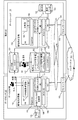
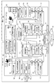
図1Aは、本実施例のシステムの構成例を示す。図1Aにおいて、同一の機能を有する異なる構成要素は、同一の符号を付されることがある。データ分析プログラムの配信元計算機111と配信先計算機112とは、ネットワーク104を介して接続されている。図1Aの例において、ネットワークは、VPN(Virtual Private Network)である。配信元計算機111はデータセンタ101に設置され、配信先計算機112はデータセンタ101とは異なる拠点に設置されている。
FIG. 1A shows a configuration example of the system of this embodiment. In FIG. 1A, different components having the same function may be labeled with the same reference numerals. The
配信元計算機111及び配信先計算機112は、VPN104又は他のネットワークを介して、I/Oログデータベース(DB)121及び構成DB122にアクセスする。I/Oログデータベース(DB)121及び構成DB122は、それぞれ、例えば、データセンタ101又は拠点102に設置されたサーバ計算機に格納される。拠点DB123は、拠点102内の、例えばサーバ計算機に格納され、配信先計算機112からアクセスされる。
The
プロキシサーバ113及び114は、それぞれ、データセンタ101及び拠点102内に設置されている。プロキシサーバ113及び114は、他の計算機と外部ネットワーク(インターネット103)との間のデータ通信を仲介する。
The
ネットワークにおけるセキュリティ境界であるデータシールド131が、システムにおいて予め定義されている。データシールド131内においては、機密データを含むデータの移動が許可されている。データシールド131は、システム内のノードにより定義される。
The
具体的には、データシールド内のノード及びデータシールドの境界ノードにより定義される。図1Aの例において、プロキシサーバ113、114は境界ノードであり、外部記憶デバイス125を除く他のノードが、シールド内ノードである。計算機は、ノードの一例である。
Specifically, it is defined by the nodes in the data shield and the boundary nodes of the data shield. In the example of FIG. 1A, the
配信先計算機112は、データ分析部143、Hypervisor145、ネットワークI/O記録&フィルタ部147、ホストOS148を含む。データ分析部143は、NIC(Network Interface Card)を介して拠点DB123内の拠点データ155を取得して、分析する。
The
データ分析部143は、プロセッサが、Hypervisor145でデータ分析プログラムを実行することで実現される。データ分析部143の分析結果は、Hypervisor145を介して、ネットワークI/O記録&フィルタ部147に送信される。ネットワークI/O記録&フィルタ部147は、プロセッサが、ホストOS148上で、ネットワークI/O記録&フィルタプログラムを実行することで実現される。
The
後述するように、ネットワークI/O記録&フィルタ部147は、データ分析部143のネットワークI/Oを監視する監視部である。ネットワークI/O記録&フィルタ部147は、構成DB122に格納されている情報を参照して、データ分析部143からのパケットのフィルタリング及びログ記録を実行する。
As will be described later, the network I / O recording &
構成DB122は、シールド内計算機IPアドレスリスト152、シールド境界計算機IPアドレスリスト153、及びフィルタポリシ154を格納している。構成DB122の情報は、顧客管理者により予め構成される。ネットワークI/O記録&フィルタ部147は、データ分析部143のI/Oログの情報を、I/OログDB121のI/Oログ151に格納する。I/Oログ151は、顧客管理者によりチェックされる。
The
分析結果は、さらに、ネットワークI/O記録&フィルタ部147から、NIC、VPN104を介して、配信元計算機111に転送される。配信先計算機112は分析結果を示すパケットの送信元計算機であり、配信元計算機111はそのパケットの受信計算機である。
The analysis result is further transferred from the network I / O recording &
配信元計算機111は、分析結果確認部141、Hypervisor145、外部デバイスI/O記録部146、ネットワークI/O記録&フィルタ部147、ホストOS148を含む。配信元計算機111において、分析結果は、NIC及びホストOS148を介して、ネットワークI/O記録&フィルタ部147に送信される。ネットワークI/O記録&フィルタ部147は、プロセッサが、ホストOS148上でネットワークI/O記録&フィルタプログラムを実行することで実現される。
The
ネットワークI/O記録&フィルタ部147は、分析結果確認部141のネットワークI/Oを監視する監視部である。ネットワークI/O記録&フィルタ部147は、構成DB122に格納されている情報を事前に読み出し保持する。ネットワークI/O記録&フィルタ部147は、構成情報を参照して、分析結果確認部141からのパケットのフィルタリング及びログ記録を実行する。ネットワークI/O記録&フィルタ部147は、分析結果確認部141のI/Oログの情報を、I/OログDB121におけるI/Oログ151に格納する。
The network I / O recording &
分析結果確認部141は、分析結果を、ネットワークI/O記録&フィルタ部147から、Hypervisor145を介して、受信する。分析結果確認部141は、データ分析者が使用するユーザ端末に送信する。分析結果は、例えば、配信元計算機111の補助記憶に格納される。分析結果確認部141は、プロセッサが、Hypervisor145でデータ分析プログラムを実行することで実現される。
The analysis
外部デバイスI/O記録部146は、分析結果確認部141の外部記憶デバイス125とのI/Oを監視し、そのログを記録する。ログは、I/Oログ151に格納される。外部デバイスI/O記録部146は、プロセッサが、ホストOS148上で外部デバイスI/O記録プログラムを実行することで実現される。
The external device I /
図1Bは、一般的な計算機構成を示す。配信元計算機111、配信先計算機112、プロキシサーバ113、114、DB121、122、123を格納する計算機、及びプロキシサーバ113、114は、例えば、図1Bに示すハードウェア構成を有する。
FIG. 1B shows a general computer configuration. The
計算機12は、CPU(Central Processing Unit)223と、CPU223が処理を実行するために必要なデータ(プログラムを含む)を格納するための主記憶224と、大量のデータを記憶する容量を持つハードディスクやフラッシュメモリなどの補助記憶225を含む。
The
計算機12は、さらに、他装置と通信を行なうためのIF(インタフェイス)222と、これらの各装置を接続する通信路227と、を含む。プロセッサであるCPU223は、主記憶224に格納されたプログラムを実行することで所定の機能を実現する機能部として動作する。
The
補助記憶225は、CPU223が使用するデータ(情報)を格納する。プログラムやデータは、あらかじめ主記憶224または非一時的記憶媒体を含む補助記憶225に格納されていてもよいし、必要な時に、IF222を介して他の装置から、インストール(ロード)されてもよい。主記憶224及び補助記憶225は、個別に又は一体でメモリを構成する。計算機12は、さらに、キーボード、ディスプレイなどの入出力を行うための入出力デバイス226を含んでもよい。なお、機能部の一部は、CPU223と異なる専用回路で実現されてもよい。
The
データシールド131は、構成DB122の情報により管理(定義)されている。具体的には、データシールド131の境界計算機及び内部計算機の情報が、構成DB122に格納される。
The
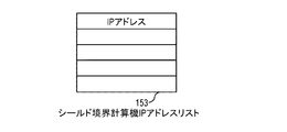
図2Aは、シールド内計算機IPアドレスリスト152の構成例を示す。シールド内計算機IPアドレスリスト152はデータシールド内の計算機のIPアドレスを示す。図2Bは、シールド境界計算機IPアドレスリスト153の構成例を示す。シールド境界計算機IPアドレスリスト153は、データシールド131の境界の計算機のIPアドレスを示す。
FIG. 2A shows a configuration example of the in-shield computer
図2Cは、フィルタポリシ154の構成例を示す。フィルタポリシ154は、ネットワークI/O記録&フィルタ部147により参照され、パケットに応じて実行すべき動作()を示す。具体的には、フィルタポリシ154は、プロトコルカラム203、readカラム204、writeカラム205、及びactionカラム206を有する。
FIG. 2C shows a configuration example of the
readカラム204及びwriteカラム205は、それぞれ、readパケット及びwriteパケットを監視することなく転送することが許可されているか禁止されているか示す。action206は、禁止されているパケットに対する処理を示す。「禁止」されているパケットに対して、例えば、破棄、ログ記録、破棄及びログ記録、の処理が実行される。
The
図3は、パケットの構成例を示す。パケットは、Ethernet(登録商標)ヘッダ301、IPヘッダ302、TCPヘッダ303、L7ヘッダ304及びL7データフィールド305を含む。Ethernetヘッダ301は、宛先MACアドレスフィールド306を含む。IPヘッダ302は、送信元IPアドレスフィールド307及び宛先IPアドレスフィールド308を含む。TCPヘッダ303は、シーケンス番号フィールド309を含む。
FIG. 3 shows a packet configuration example. The packet includes
図4は、分析結果確認部141及びデータ分析部143の処理のフローチャートを示す。分析結果確認部141は、分析部143(分析プログラム)を配信先計算機112のHypervisor145上で起動する(402)。分析部143は、拠点データ155にアクセスし、データ分析処理を実行する(403)。分析部143は、分析結果確認部141にデータ分析結果を送信する(404)。分析結果確認部141は、データ分析者の端末からの要求に応じて、データ分析結果をデータ分析者の端末において表示する(405)。
FIG. 4 shows a flowchart of processing of the analysis
データ分析結果は、配信先計算機112において、Hypervisor145、ネットワークI/O記録&フィルタ部147、ホストOS148を介して、配信元計算機111に転送される。配信元計算機111において、データ分析結果は、ホストOS148、ネットワークI/O記録&フィルタ部147、Hypervisor145を介して、分析結果確認部141に転送される。
The data analysis result is transferred to the
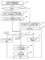
図5は、配信元計算機111及び配信先計算機112における、ネットワークI/O記録&フィルタ部147による処理を含むフローチャートを示す。分析部143又は分析結果確認部141は、Hypervisor145にI/O要求を発行する(501)。Hypervisor145は、I/O要求が、ネットワークI/O要求(ネットワークを介したI/O要求)であるか判定する(502)。
FIG. 5 shows a flowchart including processing by the network I / O recording &
図1Aの例においては、分析結果確認部141からのI/O要求は、ネットワークI/O要求ではなく、外部デバイスへのI/O要求であり得る。発行されたI/O要求がネットワークI/O要求ではない場合(502:他)、Hypervisor145は、I/O要求をホストOS148へのI/O要求に変換し、外部デバイスI/O記録部146に送信する(505)。外部デバイスI/O記録部146は、I/Oログを、I/OログDB121に出力し(506)、I/O要求をホストOS148に転送する。
In the example of FIG. 1A, the I / O request from the analysis
発行されたI/O要求がネットワークI/O要求である場合(502:ネットワークI/O)、Hypervisor145は、I/O要求をホストOS148へのI/O要求に変換し、ネットワークI/O記録&フィルタ部147に送信する(503)。ネットワークI/O記録&フィルタ部147は、I/O要求に含まれるパケットのIPヘッダ302における宛先IPアドレスフィールド308を参照し、宛先IPアドレスを特定する(504)。
When the issued I / O request is a network I / O request (502: network I / O),
ネットワークI/O記録&フィルタ部147は、シールド内計算機IPアドレスリスト152及びシールド境界計算機IPアドレスリスト153を参照し、パケットの宛先IPアドレスが、データシールド131に対して、どこに存在するか判定する(507)。
The network I / O recording &
宛先IPアドレスがシールド内IPアドレスである場合、つまり、宛先IPアドレスがシールド内計算機IPアドレスリスト152に含まれる場合(507:シールド内IPアドレス)、ネットワークI/O記録&フィルタ部147は、フィルタリング及びログ記録(監視処理)を実行することなく、I/O要求をホストOS148に転送する(508)。
When the destination IP address is a shielded IP address, that is, when the destination IP address is included in the shielded computer IP address list 152 (507: shielded IP address), the network I / O recording &
宛先IPアドレスがシールド外IPアドレスである場合、つまり、宛先IPアドレスがシールド内計算機IPアドレスリスト152及びシールド境界計算機IPアドレスリスト153に含まれない場合(507:他)、ネットワークI/O記録&フィルタ部147は、I/O要求を破棄する(511)。
If the destination IP address is an unshielded IP address, that is, if the destination IP address is not included in the shielded computer
宛先IPアドレスがシールド境界IPアドレスである場合、つまり、宛先IPアドレスがシールド境界計算機IPアドレスリスト153に含まれる場合(507:シールド境界IPアドレス)、ネットワークI/O記録&フィルタ部147は、TCPヘッダ303のシーケンス番号(フィールド309内)に基づき、パケットを再構成した(509)後、フィルタポリシ154に基づきI/O要求(パケット)を処理する(監視処理)(510)。
When the destination IP address is a shield boundary IP address, that is, when the destination IP address is included in the shield boundary computer IP address list 153 (507: shield boundary IP address), the network I / O recording &
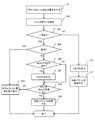
図6は、フィルタポリシ154に基づく処理(510)の詳細のフローチャートを示す。ネットワークI/O記録&フィルタ部147は、L7ヘッダ304を解析して、使用されているプロトコルと、read/write種別を判定する(601)。ネットワークI/O記録&フィルタ部147は、パケットが該当するエントリを、フィルタポリシ154においてを検索する(602)。
FIG. 6 shows a detailed flowchart of the process (510) based on the
パケットが該当するエントリがフィルタポリシ154に存在しない場合(603:NO)、ネットワークI/O記録&フィルタ部147は、I/OログをI/OログDB121に出力し(610)、当該パケットを破棄する(611)。
If the entry corresponding to the packet does not exist in the filter policy 154 (603: NO), the network I / O recording &
パケットが該当するエントリがフィルタポリシ154に存在する場合(603:YES)、ネットワークI/O記録&フィルタ部147は、当該パケットが、ホストOS148からの送信が許可されているか判定する(604)。具体的には、ネットワークI/O記録&フィルタ部147は、該当エントリのreadカラム204とwriteカラム205の内の該当カラムが、「許可」を示すか判定する。
When the corresponding entry of the packet exists in the filter policy 154 (603: YES), the network I / O recording &
当該パケットが「許可」されている場合(604:YES)、ネットワークI/O記録&フィルタ部147は、I/Oログを出力することなく、I/O要求をホストOS148に転送する(605)。
If the packet is "allowed" (604: YES), the network I / O recording &
当該パケットが「禁止」されている場合(604:NO)、ネットワークI/O記録&フィルタ部147は、当該エントリのactionカラム206の値が、「log」を含むか判定する(606)。「log」が含まれている場合(606:YES)、ネットワークI/O記録&フィルタ部147は、I/OログをI/OログDB121に出力する(607)。
When the packet is "prohibited" (604: NO), the network I / O recording &
さらに、ネットワークI/O記録&フィルタ部147は、当該エントリのactionカラム206の値が、「discard」を含むか判定する(608)。「discard」が含まれてない場合(608:NO)、ネットワークI/O記録&フィルタ部147は、I/O要求をホストOS148に転送する(605)。「discard」が含まれている場合(608:YES)、ネットワークI/O記録&フィルタ部147は、当該パケットを破棄する(609)。
Further, the network I / O recording &
上述のように本実施例の監視処理は、フィルタポリシに従い、パケットの種別(プロトコル種別及びread/write種別)に基づき、パケットの破棄/転送を決定し(フィルタリング)及びログ記録の有無を決定する。 As described above, the monitoring process of this embodiment determines the packet discard / transfer (filtering) and the presence / absence of logging based on the packet type (protocol type and read / write type) according to the filter policy. ..
以上のように、ネットワークI/O記録&フィルタ部147は、宛先IPアドレスのデータシールド131に対する位置に基づき一部のパケットのみを選択して、ログ記録及びフィルタリング(監視処理)を実行する。これにより、情報漏洩のための処理負荷を低減できる。パケットの送信元(データ分析結果確認プログラム又は分析プログラム)と同一計算機においてネットワークI/O記録&フィルタ部147が動作することで、他のハードウェア資源を使用することなく効率的にパケットを監視することができる。
As described above, the network I / O recording &
以下において、実施例2を説明する。主に、実施例1との差異を説明する。本実施例において、配信元計算機又は配信先計算機からのパケットは、ゲートウェイ計算機に転送される。ネットワークI/O記録&フィルタ部147は、ゲートウェイ計算機において、パケットのフィルタリング及びログ記録を実行する。これにより、配信元計算機及び配信先計算機の負荷を低減できる。また、複数の配信先計算機又は複数の配信元計算機のパケットを1台のゲートウェイ計算機において監視することができる。
The second embodiment will be described below. The difference from the first embodiment will be mainly described. In this embodiment, the packet from the distribution source computer or the distribution destination computer is transferred to the gateway computer. The network I / O recording &
図7は、本実施例のシステムの構成例を示す。実施例1の構成に加えて、スイッチ装置A211、ゲートウェイ計算機A213が、データセンタ101において追加され、スイッチ装置B212、ゲートウェイ計算機B214が、拠点102において追加されている。これら装置は、データシールド131内に配置されている。
FIG. 7 shows a configuration example of the system of this embodiment. In addition to the configuration of the first embodiment, the switch device A211 and the gateway computer A213 are added in the
配信先計算機112は、スイッチ装置B212を介して、ゲートウェイ計算機B214に接続されている。図7は1台の配信先計算機を示すが、複数の配信先計算機がゲートウェイ計算機B214に接続されてもよい。配信元計算機111は、スイッチ装置A211を介して、ゲートウェイ計算機A213に接続されている。図7は1台の配信元計算機を示すが、複数の配信元計算機がゲートウェイ計算機A213に接続されてもよい。
The
ゲートウェイ計算機A213、ゲートウェイ計算機B214は、VPN104を介して接続されている。配信元計算機111及び配信先計算機112は、それぞれ、ゲートウェイ計算機A213及びゲートウェイ計算機B214を介して、プロキシサーバ113及び114に接続されている。
The gateway computer A213 and the gateway computer B214 are connected via the
ゲートウェイ計算機A213、ゲートウェイ計算機B214は、それぞれ、転送制御テーブル252、パケット転送部242、ネットワークI/O記録&フィルタ部147を含む。ゲートウェイ計算機A213、ゲートウェイ計算機B214は、それぞれ、はNICを介して他装置(ネットワーク)に接続されているに接続されている。パケット転送部242は、プロセッサがプログラムを実行することで実現される。
The gateway computer A213 and the gateway computer B214 include a transfer control table 252, a
スイッチ装置A211、スイッチ装置B212は、それぞれ、パケット検査部241を含む。スイッチ装置A211、スイッチ装置B212は、それぞれ、はNICを介して他装置(ネットワーク)に接続されているに接続されている。パケット検査部241は、例えば、プロセッサがプログラムを実行することにより実現される。
The switch device A211 and the switch device B212 each include a
本実施例において、ネットワークI/O記録&フィルタ部147は、配信元計算機111及び配信先計算機112に代えて、ゲートウェイ計算機A213及びゲートウェイ計算機B214に実装されている。構成DB122は、実施例1の情報に加え、ゲートウェイ計算機IP/MACアドレスリスト251を格納している。
In this embodiment, the network I / O recording &
図8は、転送制御テーブル252の構成例を示す。転送制御テーブル252は、パケットの宛先アドレスと転送先アドレスとを関連付ける。転送制御テーブル252は、宛先IPアドレスカラム1001、転送先IPアドレスカラム1002、及び転送先MACアドレスカラム1003を有する。
FIG. 8 shows a configuration example of the transfer control table 252. The forwarding control table 252 associates the destination address of the packet with the forwarding address. The transfer control table 252 has a destination
図9は、ゲートウェイ計算機IPアドレス/MACアドレスリスト251の構成例を示す。ゲートウェイ計算機IPアドレス/MACアドレスリスト251は、ゲートウェイ計算機のアドレスを管理する。ゲートウェイ計算機IPアドレス/MACアドレスリスト251は、IPアドレスカラム1101及びMACアドレスカラム1102を有する。各エントリは、ゲートウェイ計算機のIPアドレスとMACアドレスとを示す。ゲートウェイ計算機IPアドレス/MACアドレスリスト251は、顧客管理者により予め設定される。
FIG. 9 shows a configuration example of the gateway computer IP address /
図10は、転送制御テーブル252を作成するフローチャートを示す。ゲートウェイ計算機A213、ゲートウェイ計算機B214は、それぞれ、シールド内計算機IPアドレスリスト152に記載されている宛先IPアドレス用の転送制御テーブルエントリを作成する(1201)。ゲートウェイ計算機A213、ゲートウェイ計算機B214は、それぞれ、転送先IPアドレスカラム1002、転送先MACアドレスカラム1003にゲートウェイ計算機のIPアドレス及びMACアドレスを設定する(1202)。
FIG. 10 shows a flowchart for creating the transfer control table 252. The gateway computer A213 and the gateway computer B214 each create a transfer control table entry for the destination IP address described in the in-shield computer IP address list 152 (1201). The gateway computer A213 and the gateway computer B214 set the IP address and MAC address of the gateway computer in the transfer destination
図11は、配信元計算機111及び配信先計算機112における処理のフローチャートを示す。ステップ801から805は、それぞれ、図5のステップ501から503、505、506に対応する。配信元計算機111及び配信先計算機112にネットワークI/O記録&フィルタ部147が実装されていないため、図5のフローチャートにおけるそのステップは省略されている。
FIG. 11 shows a flowchart of processing in the
図12は、スイッチ装置A211、スイッチ装置B212の処理のフローチャートを示す。パケット検査部241は、受信したパケットの宛先MACアドレスを特定する(901)。パケット検査部241は、受信したパケットのEthernetヘッダ301における宛先MACアドレスフィールド306を参照する。
FIG. 12 shows a flowchart of processing of the switch device A211 and the switch device B212. The
パケット検査部241は、ゲートウェイ計算機IPアドレス/MACアドレスリスト251を参照し、宛先MACアドレスが、ゲートウェイ計算機のMACアドレスか判定する(902)。パケット検査部241は、ゲートウェイ計算機IPアドレス/MACアドレスリスト251を、事前に構成DB122から読み込み、保持している。
The
宛先MACアドレスが、ゲートウェイ計算機のMACアドレスである場合(902:YES)、スイッチ装置A211/スイッチ装置B212は、当該パケットをゲートウェイ計算機に転送する(903)。宛先MACアドレスが、ゲートウェイ計算機のMACアドレスではない場合(902:NO)、パケット検査部241は、当該パケットを破棄する(904)。
When the destination MAC address is the MAC address of the gateway computer (902: YES), the switch device A211 / switch device B212 forwards the packet to the gateway computer (903). If the destination MAC address is not the MAC address of the gateway computer (902: NO), the
図12の処理により、スイッチ装置A211上で動作するパケット検査部241は、配信元計算機111からゲートウェイ計算機A213を介して送信されるIPパケット以外のパケットをブロック(破棄)する。スイッチ装置B212上で動作するパケット検査部211は、配信先計算機112からゲートウェイ計算機B214を介して送信されるIPパケット以外のパケットをブロック(破棄)する。これにより、配信元計算機111及び配信先計算機112からの全てネットワークパケットは、ゲートウェイ計算機を通過する。
By the process of FIG. 12, the
図13は、ゲートウェイ計算機A213/ゲートウェイ計算機B214におけるパケット転送部242の処理のフローチャートを示す。パケット転送部242は、スイッチ装置からパケットを受信すると、当該パケットの宛先IPアドレスを特定する(1301)。パケット転送部242は、受信パケットのIPヘッダ302における宛先IPアドレスフィールド308を参照する。
FIG. 13 shows a flowchart of processing of the
パケット転送部242は、転送制御テーブル252を参照し、該当エントリの転送先MACアドレスを取得する(1302)。パケット転送部242は、当該パケットのEthernetヘッダ301の宛先MACアドレスフィールド306に、上記転送先MACアドレスを設定する(1303)。
The
パケット転送部242は、ゲートウェイ計算機IPアドレス/MACアドレスリスト251を参照し、転送先MACアドレスがゲートウェイ計算機のアドレスであるか判定する(1304)。転送先MACアドレスがゲートウェイ計算機である場合(1304:ゲートウェイ計算機)、パケット転送部242は、転送先に当該パケットを転送する(1305)。転送先MACアドレスがゲートウェイ計算機でない場合(1304:他)、パケット転送部242は、当該パケットをネットワークI/O記録&フィルタ部147に送信する(1306)。
The
図13の処理により、ネットワークI/O記録装置&フィルタ部147が処理するパケットを、データシールド境界を含む外部宛パケットのみに制限できる。パケット転送部242は、他方のゲートウェイ計算機から受信したパケットを、宛先IPアドレスに従って転送する。
By the processing of FIG. 13, the packets processed by the network I / O recording device &
図14は、ゲートウェイ計算機A213/ゲートウェイ計算機B214におけるネットワークI/O記録&フィルタ部147の処理のフローチャートを示す。ネットワークI/O記録&フィルタ部147は、パケット転送部242から受信したパケットのIPヘッダ302における宛先IPアドレスフィールド308を参照し、宛先IPアドレスを特定する(1401)。
FIG. 14 shows a flowchart of processing of the network I / O recording &
ネットワークI/O記録&フィルタ部147は、シールド境界計算機IPアドレスリスト153を参照し、パケットの宛先IPアドレスが、シールド境界のアドレスであるか判定する(1402)。
The network I / O recording &
宛先IPアドレスがシールド外IPアドレスである場合、つまり、宛先IPアドレスがシールド境界計算機IPアドレスリスト153に含まれない場合(1402:他)、ネットワークI/O記録&フィルタ部147は、当該パケットを破棄する(1405)。
When the destination IP address is an unshielded IP address, that is, when the destination IP address is not included in the shield boundary computer IP address list 153 (1402: etc.), the network I / O recording &
宛先IPアドレスがシールド境界IPアドレスである場合、つまり、宛先IPアドレスがシールド境界計算機IPアドレスリスト153に含まれる場合(1402:シールド境界IPアドレス)、ネットワークI/O記録&フィルタ部147は、TCPヘッダ303のシーケンス番号(フィールド309内)に基づき、パケットを再構成する(1403)。
When the destination IP address is a shield boundary IP address, that is, when the destination IP address is included in the shield boundary computer IP address list 153 (1402: shield boundary IP address), the network I / O recording &
ネットワークI/O記録&フィルタ部147は、フィルタポリシ154及びL7ヘッダ304に基づき、パケットを処理する(1404)。ステップ1404は、図6を参照した説明のように、パケットフィルタリング及び不ログ記録を実行する。廃棄されないパケットは、プロキシサーバに転送される。
The network I / O recording &
以下において、実施例3を説明する。主に、実施例2との差異を説明する。本実施例において、ネットワークI/O記録&フィルタ部147は、ゲートウェイ計算機とは異なるフィルタ計算機に実装される。ゲートウェイ計算機や配信元/配信先計算機と異なる計算機に実装することで、それら計算機の負荷を低減できる。また。既存のネットワークシステムに用意にネットワークI/O記録&フィルタ部147を組み込むことができる。
The third embodiment will be described below. The difference from the second embodiment will be mainly described. In this embodiment, the network I / O recording &
図15は、本実施例のシステムの構成例を示す。実施例2の構成と比較して、拠点102のゲートウェイ計算機B214、スイッチ装置B212及びプロキシサーバ114が省略されている。フィルタ計算機1511がデータセンタ101において追加されている。
FIG. 15 shows a configuration example of the system of this embodiment. Compared with the configuration of the second embodiment, the gateway computer B214, the switch device B212, and the
配信元計算機111は、スイッチ装置A211を介して、ゲートウェイ計算機A213に接続されている。ゲートウェイ計算機A213とスイッチ装置B212とは、VPN104を介して接続されている。配信先計算機112は、スイッチ装置B212を介して、ゲートウェイ計算機A213に接続されている。フィルタ計算機1511は、ゲートウェイ計算機A213及びプロキシサーバ113に接続されている。
The
ネットワークI/O記録&フィルタ部147は、ゲートウェイ計算機に代えて、フィルタ計算機1511に実装されている。フィルタ計算機1511は、NICを介して他装置に接続される。構成DB122は、実施例2の情報に加え、フィルタ計算機IPアドレス/MACアドレスリスト251を格納している。フィルタ計算機IPアドレス/MACアドレスリスト251は、顧客管理者により予め設定されている。
The network I / O recording &
図16は、フィルタ計算機IPアドレス/MACアドレスリスト251の構成例を示す。フィルタ計算機IPアドレス/MACアドレスリスト251は、フィルタ計算機1511のアドレスを管理する。フィルタ計算機IPアドレス/MACアドレスリスト251は、IPアドレスカラム1601及びMACアドレスカラム1602を有する。
FIG. 16 shows a configuration example of the filter computer IP address /
図17は、転送制御テーブル252を作成するフローチャートを示す。ゲートウェイ計算機A213は、シールド内計算機IPアドレスリスト152に記載されている宛先IPアドレス用の転送制御テーブルエントリを作成し、転送先IPアドレスカラム1002及び転送先MACアドレスカラム1003に、シールド内計算機のIPアドレス及びMACアドレスをそれぞれ設定する(1701)。
FIG. 17 shows a flowchart for creating the transfer control table 252. The gateway computer A213 creates a transfer control table entry for the destination IP address listed in the in-shield computer
ゲートウェイ計算機A213は、default用の転送制御テーブルエントリを作成し、転送先IPアドレスカラム1002及び転送先MACアドレスカラム1003に、フィルタ計算機1511のIPアドレス及びMACアドレスをそれぞれ設定する(1702)。
The gateway computer A213 creates a transfer control table entry for default, and sets the IP address and MAC address of the
スイッチ装置A211のパケット検査部241は、構成DB112から、ゲートウェイ計算機IPアドレス/MACアドレスリスト251を読み込み、配信元計算機111からゲートウェイ計算機A213を介して転送されるIPパケット以外のパケットをブロック(破棄)する。
The
スイッチ装置B212のパケット検査部241は、構成DB112から、ゲートウェイ計算機IPアドレス/MACアドレスリスト251を読み込み、配信先計算機112からゲートウェイ計算機A213を介して転送されるIPパケット以外のパケットをブロック(破棄)する。これにより、配信元計算機111及び配信先計算機112からの全ての生存パケットは、ゲートウェイ計算機A213を通過する。
The
図18は、ゲートウェイ計算機A213におけるパケット転送部242の処理のフローチャートを示す。パケット転送部242は、パケットを受信すると、当該パケットの宛先IPアドレスを特定する(1801)。パケット転送部242は、受信パケットのIPヘッダ302における宛先IPアドレスフィールド308を参照する。
FIG. 18 shows a flowchart of processing of the
パケット転送部242は、転送制御テーブル252において、受信パケットのIPアドレスを検索する。合致するIPアドレスが存在する場合、パケット転送部242は、対応するMACアドレスを取得し(1802)、当該パケットのEthernetヘッダの宛先MACアドレスフィールドに、上記転送先MACアドレスを設定する(1803)。
The
合致するIPアドレスが存在しない場合、パケット転送部242は、defaultのエントリから、フィルタ計算機1511のMACアドレスを取得し(1802)、当該パケットのEthernetヘッダの宛先MACアドレスフィールドに、フィルタ計算機1511のMACアドレスを設定する(1803)。これにより、データシールド131の外部(シールド境界計算機を介して又は介さず)に向かうパケットのみがフィルタ計算機1511に転送され、フィルタ計算機1511の負荷を低減できる。
If there is no matching IP address, the
パケット転送部242は、設定したMACアドレスに対してパケットを転送する(1804)。フィルタ計算機1511のネットワークI/O記録&フィルタ部147は、実施例2の図14に示すフローチャートが示すようにパケットのフィルタリング及びログ記録を実行する。
The
なお、本例は一つのゲートウェイ計算機を示すが、実施例2のように、複数のゲートウェイ計算機に異なるフィルタ計算機が接続されてもよい。一つのフィルタ計算機が複数のゲートウェイ計算機に接続されてもよい。 Although this example shows one gateway computer, different filter computers may be connected to a plurality of gateway computers as in the second embodiment. One filter computer may be connected to a plurality of gateway computers.
以下において、実施例4を説明する。主に、実施例1との差異を説明する。顧客管理者は、機密情報を含むデータ領域(taint領域)を予め設定する。ネットワークI/O記録&フィルタ部は、taint領域からのデータの転送を監視し、他の領域からのデータは監視対象から除外される。ネットワークI/O記録&フィルタ部は、taint領域からデータが読み出されると、taint領域追跡部に追跡指示を発行する。 The fourth embodiment will be described below. The difference from the first embodiment will be mainly described. The customer manager sets a data area (taint area) including confidential information in advance. The network I / O recording & filtering unit monitors the transfer of data from the taint area, and data from other areas is excluded from the monitoring target. When the data is read from the taint area, the network I / O recording & filter unit issues a tracking instruction to the taint area tracking unit.
taint領域追跡部は、データ分析部/データ分析結果確認部のメモリアクセスを追跡し、taint領域から読み出されたデータの伝播を解析する。これにより、分析部/分析結果確認部からの情報漏洩を効率的に監視できる。 The taint area tracking unit tracks the memory access of the data analysis unit / data analysis result confirmation unit, and analyzes the propagation of the data read from the taint area. As a result, information leakage from the analysis unit / analysis result confirmation unit can be efficiently monitored.
図19は、本実施例のシステムの構成例を示す。実施例1の構成に加え、配信元計算機111及び配信先計算機112において、taint領域追跡部1941が実装されている。taint領域追跡部1941は、taint bitmap1952を含む。taint領域追跡部1941は、CPU223がtaint領域追跡プログラムを実行することにより実現される。構成DB122は、taint領域リスト1951を格納する。
FIG. 19 shows a configuration example of the system of this embodiment. In addition to the configuration of the first embodiment, the tint
図20は、taint領域リスト1951の構成例を示す。taint領域リスト1951は、ストレージのtaint領域を管理する。taint領域リスト1951は、ストレージIPアドレスカラム2001、開始セクタ番号カラム2002、終了セクタ番号カラム2003を有する。
FIG. 20 shows a configuration example of the
図21は、taint bitmap1952の構成例を示す。taint bitmap1952は、メモリにおける領域(の格納データ)が、taint領域(の格納データ)であるかを示す。taint bitmap1952は、ページアドレスカラム2101及びtaint有無ビットカラム2102を有する。ページは、メモリにおける管理単位領域である。
FIG. 21 shows a configuration example of the
図22は、taint領域追跡部1941による処理のフローチャートを示す。taint領域追跡部1941は、taint領域受信通知をネットワークI/O記録&フィルタ部147から受信する(2201)。taint領域追跡部1941は、当該メモリ領域をtaint領域として登録するようtaint bitmap1952を更新する(2202)。taint領域追跡部1941は、Hypervisor145経由で、分析部143/分析結果確認部141にパケット受信を通知する(2203)。
FIG. 22 shows a flowchart of processing by the taint
図23は、配信先計算機112及び配信元計算機111それぞれにおける処理のフローチャートを示す。分析部143/分析結果確認部141は、Hypervisor145に命令実行要求を発行する(2301)。Hypervisor145は、taint領域追跡部1941に命令実行通知を発行する(2302)。
FIG. 23 shows a flowchart of processing in each of the
taint領域追跡部1941は、命令解析を実行する(2303)。taint領域から読んだデータのメモリwrite発生している場合(2304:YES)、taint領域追跡部1941は、当該メモリ領域をtaint領域として登録するよう、taint bitmap1952を更新する(2305)。これにより、taint領域を追跡できる。taint領域から読んだデータのメモリwrite発生していない場合(2304:NO)、ステップ2305はスキップされる。
The taint
taint領域以外から読んだデータのメモリwrite発生している場合(2306:YES)、taint領域追跡部1941は、当該メモリ領域をtaint領域から削除するようtaint bitmap1952を更新する(2307)。taint領域以外から読んだデータのメモリwrite発生していない場合(2306:NO)、ステップ2307はスキップされる。
When a memory write of data read from other than the taint area is generated (2306: YES), the taint
taint領域追跡部1941は、Hypervisor145に再開要求を発行し、Hypervisor145は、分析部143/分析結果確認部141を再開する(2308)。
The taint
図24は、ネットワークI/O記録&フィルタ部147による受信パケットの処理のフローチャートを示す。ネットワークI/O記録&フィルタ部147は、NIC経由でパケットを受信する(2401)。ネットワークI/O記録&フィルタ部147は、受信したパケットが、ストレージI/Oによるパケットであるか判定する(2402)。パケットの送信元IPアドレスフィールド307の値と一致するIPアドレスがtaint領域リスト1951に存在する場合、ネットワークI/O記録&フィルタ部147は、受信したパケットが、ストレージI/Oによるパケットであると判定する。
FIG. 24 shows a flowchart of processing of received packets by the network I / O recording &
パケットが、ストレージI/Oによるパケットである場合(2402:YES)、ネットワークI/O記録&フィルタ部147は、パケットにおいてデータが読み出されたセクタを同定し、taint領域リスト1951を参照して、当該セクタがtaint領域であるか判定する(2403)。
When the packet is a packet by storage I / O (2402: YES), the network I / O recording &
当該セクタがtaint領域である場合(2403:YES)、ネットワークI/O記録&フィルタ部147は、受信メモリ領域をtaint領域に登録するよう、taint領域追跡部1941にtaint領域受信通知を発行する(2404)。これにより、taint領域が追跡される。当該セクタがtaint領域でない場合(2403:他)、ステップ2404はスキップされる。
When the sector is a taint area (2403: YES), the network I / O recording &
パケットが、ストレージI/Oによるパケットではない場合(2402:NO)、ネットワークI/O記録&フィルタ部147は、受信パケットのIPヘッダ302がtaintマークを含むか判定する(2405)。
When the packet is not a packet by storage I / O (2402: NO), the network I / O recording &
IPヘッダ302がtaintマークを含む場合(2405:YES)、ネットワークI/O記録&フィルタ部147は、受信メモリ領域をtaint領域に登録するよう、taint領域追跡部1941にtaint領域受信通知を発行する(2406)。taintマークにより、ノード間でtaint領域のデータを追跡できる。IPヘッダ302がtaintマークを含まない場合(2405:NO)、ネットワークI/O記録&フィルタ部147は、Hypervisor145経由で、分析部143/分析結果確認部141にパケット受信を通知する(2407)。
When the
図25は、ネットワークI/O記録&フィルタ部147による送信パケットの処理のフローチャートを示す。ネットワークI/O記録&フィルタ部147は、taint領域追跡部1941よりtaint領域送信通知を受信する(2501)。ネットワークI/O記録&フィルタ部147は、taint領域のデータについて以下のステップを実行する。
FIG. 25 shows a flowchart of processing of transmitted packets by the network I / O recording &
ネットワークI/O記録&フィルタ部147は、当該パケットのIPヘッダ302の宛先IPアドレスフィールド308を参照し、宛先IPアドレスを特定する(2502)。宛先がシールド境界計算機である場合、つまり、宛先IPアドレスがシールド境界計算機IPアドレスリスト153に存在する場合(2503:シールド境界サーバ)、ネットワークI/O記録&フィルタ部147は、フィルタポリシ154及びパケット種別に基づいて、パケットを処理する(2504)。ネットワークI/O記録&フィルタ部147は、読みされたデータのファイル情報を復元し、I/Oログに含める。
The network I / O recording &
宛先がシールド内計算機である場合、つまり、宛先IPアドレスがシールド内計算機IPアドレスリスト152に存在する場合(2503:シールド内計算機)、ネットワークI/O記録&フィルタ部147は、当該パケットのIPヘッダ302にtaintマークを設定してNIC経由で送信する(2505)。
When the destination is an in-shield computer, that is, when the destination IP address exists in the in-shield computer IP address list 152 (2503: in-shield computer), the network I / O recording &
宛先が、シールド境界外アドレスである、つまり、シールド境界計算機でも、シールド境界内計算機でもない場合(2503:他)、ネットワークI/O記録&フィルタ部147は、当該パケットを破棄する(2506)。
When the destination is an address outside the shield boundary, that is, neither the shield boundary computer nor the shield boundary computer (2503: etc.), the network I / O recording &
上述のように、ネットワークI/O記録&フィルタ部147は、宛先がシールド内計算機であり、かつ、taint領域からのネットワークパケット(ネットワークI/O)を検出すると、当該ネットワークパケットにtaintマークを設定する。また。ネットワークI/O記録&フィルタ部147は、taintマークが設定されたネットワークパケット受信を検出すると、taint領域追跡部にtaint領域受信通知(追跡指示)を発行する。これにより、taint領域追跡処理が、他ノードに承継される。
As described above, the network I / O recording &
ネットワークI/O記録&フィルタ部147は、宛先がシールド境界計算機であり、かつ、taint領域からのネットワークパケット(ネットワークI/O)を検出すると、パケットに対するフィルタリング及びログ記録(監視処理)を実行する。taint領域からシールド境界計算機へのネットワークI/O以外のパケットの解析及びログ出力が不要であり、負荷を低減することができる。
When the destination is a shield boundary computer and a network packet (network I / O) from the tint area is detected, the network I / O recording &
なお、本発明は上記した実施例に限定されるものではなく、様々な変形例が含まれる。例えば、上記した実施例は本発明を分かりやすく説明するために詳細に説明したものであり、必ずしも説明したすべての構成を備えるものに限定されるものではない。また、ある実施例の構成の一部を他の実施例の構成に置き換えることが可能であり、また、ある実施例の構成に他の実施例の構成を加えることも可能である。また、各実施例の構成の一部について、他の構成の追加・削除・置換をすることが可能である。 The present invention is not limited to the above-mentioned examples, and includes various modifications. For example, the above-described embodiment has been described in detail in order to explain the present invention in an easy-to-understand manner, and is not necessarily limited to the one including all the configurations described. Further, it is possible to replace a part of the configuration of one embodiment with the configuration of another embodiment, and it is also possible to add the configuration of another embodiment to the configuration of one embodiment. Further, it is possible to add / delete / replace a part of the configuration of each embodiment with another configuration.
また、上記の各構成・機能・処理部等は、それらの一部又は全部を、例えば集積回路で設計する等によりハードウェアで実現してもよい。また、上記の各構成、機能等は、プロセッサがそれぞれの機能を実現するプログラムを解釈し、実行することによりソフトウェアで実現してもよい。各機能を実現するプログラム、テーブル、ファイル等の情報は、メモリや、ハードディスク、SSD(Solid State Drive)等の記録装置、または、ICカード、SDカード等の記録媒体に置くことができる。 In addition, each of the above-mentioned configurations, functions, processing units, and the like may be realized by hardware, for example, by designing a part or all of them with an integrated circuit. Further, each of the above configurations, functions, and the like may be realized by software by the processor interpreting and executing a program that realizes each function. Information such as programs, tables, and files that realize each function can be stored in a memory, a hard disk, a recording device such as an SSD (Solid State Drive), or a recording medium such as an IC card or an SD card.
また、制御線や情報線は説明上必要と考えられるものを示しており、製品上必ずしもすべての制御線や情報線を示しているとは限らない。実際には殆どすべての構成が相互に接続されていると考えてもよい。 In addition, control lines and information lines are shown as necessary for explanation, and not all control lines and information lines are shown in the product. In practice, it can be considered that almost all configurations are interconnected.
101 データセンタ、102 拠点、103 インターネット、104 ネットワーク、111 配信元計算機、112 配信先計算機、113、114 プロキシサーバ、125 外部記憶デバイス、131 データシールド、141 分析結果確認部、143 分析部、146 外部デバイスI/O記録部、147 ネットワークI/O記録&フィルタ部、151 I/Oログ、152 シールド内計算機IPアドレスリスト、153 シールド境界計算機IPアドレスリスト、154 フィルタポリシ、155 拠点データ、211、212 スイッチ装置、213、214 ゲートウェイ計算機、223 CPU、224 主記憶、225 補助記憶、226 入出力デバイス、241 パケット検査部、242 パケット転送部、1511 フィルタ計算機 101 data center, 102 bases, 103 Internet, 104 network, 111 source computer, 112 destination computer, 113, 114 proxy server, 125 external storage device, 131 data shield, 141 analysis result confirmation unit, 143 analysis unit, 146 external Device I / O recording unit, 147 network I / O recording & filter unit, 151 I / O log, 152 In-shield computer IP address list, 153 Shield boundary computer IP address list, 154 filter policy, 155 base data, 211, 212 Switch device, 213, 214 gateway computer, 223 CPU, 224 main storage, 225 auxiliary storage, 226 input / output device, 241 packet inspection unit, 242 packet transfer unit, 1511 filter computer
Claims (15)
プロセッサと、
前記プロセッサが実行するプログラムを格納するメモリと、を含み、
前記プロセッサは、
前記パケット送信元から送信されたパケットの宛先ネットワークアドレスの前記セキュリティ境界に対する位置を、前記セキュリティ境界上のネットワークアドレスと前記セキュリティ境界内のネットワークアドレスとを管理する管理情報に基づいて、特定し、
前記宛先ネットワークアドレスが前記セキュリティ境界外のアドレスであるパケットを破棄し、
前記宛先ネットワークアドレスが前記セキュリティ境界上のネットワークアドレスであるパケットに対して監視処理を実行する、装置。 A device that monitors packets sent from packet sources located within the security boundaries defined by the network address.
With the processor
Includes memory for storing programs executed by the processor
The processor
The position of the destination network address of the packet transmitted from the packet source with respect to the security boundary is specified based on the management information that manages the network address on the security boundary and the network address within the security boundary.
Drop packets whose destination network address is outside the security boundaries
A device that executes monitoring processing for packets whose destination network address is a network address on the security boundary.
前記プロセッサは、前記宛先ネットワークアドレスが前記セキュリティ境界内のネットワークアドレスであるパケットを、前記監視処理を実行することなく転送する、装置。 The device according to claim 1.
The processor is a device that forwards a packet whose destination network address is a network address within the security boundary without executing the monitoring process.
前記プロセッサは、前記監視処理において、パケットの種別に基づくフィルタリング、及び、パケットのログ記録の少なくとも一方を実行する、装置。 The device according to claim 1.
The processor is a device that executes at least one of filtering based on a packet type and logging of a packet in the monitoring process.
前記パケット送信元は、前記装置で実行されているプログラムである、装置。 The device according to claim 2.
The packet source is a device, which is a program executed by the device.
ネットワークを介して、前記パケット送信元である計算機から送信されたパケットを受信する、装置。 The device according to claim 2.
A device that receives a packet transmitted from a computer that is the source of the packet via a network.
前記パケット送信元である計算機から送信されたパケットのうち、ゲートウェイ計算機において選択された、前記宛先ネットワークアドレスが前記セキュリティ境界上のネットワークアドレスのパケット及び前記セキュリティ境界外のネットワークアドレスのパケットを受信する、装置。 The device according to claim 1.
Among the packets transmitted from the computer that is the packet source, the packet whose destination network address is the network address on the security boundary and the packet of the network address outside the security boundary selected by the gateway computer are received. apparatus.
前記プロセッサは、
前記宛先ネットワークアドレスが前記セキュリティ境界上のネットワークアドレスであり、かつ、予め設定されたセキュリティ境界内の記憶領域からのデータであることを示すマークを含むパケットに対して、前記監視処理を実行し、
前記宛先ネットワークアドレスが前記セキュリティ境界上のネットワークアドレスであり、かつ、前記予め設定されたセキュリティ境界内の記憶領域からのデータであることを示すマークを含まないパケットを、前記監視処理を実行することなく転送する、装置。 The device according to claim 1.
The processor
The monitoring process is executed for a packet including a mark indicating that the destination network address is a network address on the security boundary and data is from a storage area within the security boundary set in advance.
The monitoring process is executed for a packet that does not include a mark indicating that the destination network address is a network address on the security boundary and is data from a storage area within the preset security boundary. A device that transfers without.
前記プロセッサは、宛先アドレスがシールド境界内のIPアドレスである送信パケットに前記マークを含める、装置。 The device according to claim 7.
The processor includes the mark in a transmission packet whose destination address is an IP address within a shield boundary.
前記パケット送信元計算機からの前記所定のパケットを受信するパケット受信計算機と、
前記パケット送信元計算機及び前記パケット受信計算機の一方から送信されるパケットを監視する監視部と、を含み、
前記監視部は、
前記パケット送信元計算機及び前記パケット受信計算機の前記一方から送信されたパケットの宛先ネットワークアドレスの前記セキュリティ境界に対する位置を、前記セキュリティ境界上のネットワークアドレスと前記セキュリティ境界内のネットワークアドレスとを管理する管理情報に基づいて特定し、
前記宛先ネットワークアドレスが前記セキュリティ境界外のアドレスであるパケットを破棄し、
前記宛先ネットワークアドレスが前記セキュリティ境界上のネットワークアドレスであるパケットに対して監視処理を実行する、システム。 A packet source computer that is located within the security boundaries defined by the network address and sends a given packet,
A packet reception computer that receives the predetermined packet from the packet source computer, and
Includes a monitoring unit that monitors packets transmitted from one of the packet source computer and the packet reception computer.
The monitoring unit
Management of managing the position of the destination network address of a packet transmitted from one of the packet source computer and the packet reception computer with respect to the security boundary between the network address on the security boundary and the network address within the security boundary. Informed identification,
Drop packets whose destination network address is outside the security boundaries
A system that performs monitoring processing on packets whose destination network address is a network address on the security boundary.
前記監視部は、前記宛先ネットワークアドレスが前記セキュリティ境界内のネットワークアドレスであるパケットを、前記監視処理を実行することなく転送する、システム。 The system according to claim 9.
The monitoring unit is a system that forwards a packet whose destination network address is a network address within the security boundary without executing the monitoring process.
前記パケット受信計算機は、前記監視部を含み、
前記監視部は、前記パケット受信計算機から送信されるパケットを監視し、
前記パケット送信元計算機は、第2監視部を含み、
前記第2監視部は、
前記管理情報に基づいて、前記パケット送信元計算機から送信されるパケットの宛先ネットワークアドレスと前記セキュリティ境界との関係を特定し、
前記宛先ネットワークアドレスが前記セキュリティ境界外のアドレスであるパケットを破棄し、
前記宛先ネットワークアドレスが前記セキュリティ境界上のネットワークアドレスであるパケットに対して監視処理を実行し、
前記宛先ネットワークアドレスが前記セキュリティ境界内のネットワークアドレスであるパケットを、前記監視処理を実行することなく転送する、システム。 The system according to claim 10.
The packet reception computer includes the monitoring unit.
The monitoring unit monitors the packet transmitted from the packet reception computer, and the monitoring unit monitors the packet.
The packet source computer includes a second monitoring unit.
The second monitoring unit
Based on the management information, the relationship between the destination network address of the packet transmitted from the packet source computer and the security boundary is specified.
Drop packets whose destination network address is outside the security boundaries
A monitoring process is executed for a packet whose destination network address is a network address on the security boundary.
A system that forwards a packet whose destination network address is a network address within the security boundary without executing the monitoring process.
前記セキュリティ境界内の第1ゲートウェイ計算機と第2ゲートウェイ計算機とをさらに含み、
前記第1ゲートウェイ計算機は転送部と前記監視部とを含み、
前記第2ゲートウェイ計算機は第2転送部と第2監視部とを含み、
前記転送部は、前記パケット受信計算機から送信されたパケットのうち、ネットワークアドレスが前記第2ゲートウェイ計算機と異なるパケットを選択して、前記監視部に送信し、
前記第2転送部は、前記パケット送信元計算機から送信されたパケットのうち、ネットワークアドレスが前記第1ゲートウェイ計算機と異なるパケットを選択して、前記第2監視部に送信し、
前記第2監視部は、
前記管理情報に基づいて、前記パケット送信元計算機から送信されるパケットの宛先ネットワークアドレスと前記セキュリティ境界との関係を特定し、
前記宛先ネットワークアドレスが前記セキュリティ境界外のアドレスであるパケットを破棄し、
前記宛先ネットワークアドレスが前記セキュリティ境界上のネットワークアドレスであるパケットに対して監視処理を実行する、システム。 The system according to claim 9.
Further including a first gateway computer and a second gateway computer within the security boundary,
The first gateway computer includes a transfer unit and a monitoring unit.
The second gateway computer includes a second transfer unit and a second monitoring unit.
The transfer unit selects a packet having a network address different from that of the second gateway computer from the packets transmitted from the packet reception computer, and transmits the packet to the monitoring unit.
The second transfer unit selects a packet having a network address different from that of the first gateway computer from the packets transmitted from the packet source computer, and transmits the packet to the second monitoring unit.
The second monitoring unit
Based on the management information, the relationship between the destination network address of the packet transmitted from the packet source computer and the security boundary is specified.
Drop packets whose destination network address is outside the security boundaries
A system that performs monitoring processing on packets whose destination network address is a network address on the security boundary.
前記パケット送信元計算機及び前記パケット受信計算機の前記一方から送信されたパケットを転送するゲートウェイ計算機と、
前記監視部を含む監視計算機と、をさらに含み、
前記ゲートウェイ計算機は、前記パケット送信元計算機及び前記パケット受信計算機の前記一方からのパケットのうち、前記宛先ネットワークアドレスが前記セキュリティ境界上のネットワークアドレスのパケット及び前記セキュリティ境界外のネットワークアドレスのパケットを選択して、前記監視計算機に転送する、システム。 The system according to claim 9.
A gateway computer to forward a packet transmitted from said one of said packet source computer and the packet receiving computer,
Further including a monitoring computer including the monitoring unit,
The gateway computer selects a packet whose destination network address is a network address on the security boundary and a packet whose network address is outside the security boundary from among the packets from the packet source computer and the packet reception computer. Then, the system transfers to the monitoring computer.
前記パケット送信元から送信されたパケットの宛先ネットワークアドレスの前記セキュリティ境界に対する位置を、前記セキュリティ境界上のネットワークアドレスと前記セキュリティ境界内のネットワークアドレスとを管理する管理情報を参照して特定し、
前記宛先ネットワークアドレスが前記セキュリティ境界外のアドレスであるパケットを破棄し、
前記宛先ネットワークアドレスが前記セキュリティ境界上のネットワークアドレスであるパケットに対して監視処理を実行する、ことを含む方法。 A method of monitoring packets sent from packet sources located within the security boundaries defined by the network address.
The position of the destination network address of the packet transmitted from the packet source with respect to the security boundary is specified by referring to the management information for managing the network address on the security boundary and the network address within the security boundary.
Drop packets whose destination network address is outside the security boundaries
A method comprising performing a monitoring process on a packet whose destination network address is a network address on the security boundary.
さらに、前記宛先ネットワークアドレスが前記セキュリティ境界内のネットワークアドレスであるパケットを、前記監視処理を実行することなく転送する、ことを含む方法。 The method according to claim 14.
Further, a method including forwarding a packet whose destination network address is a network address within the security boundary without executing the monitoring process.
Priority Applications (1)
| Application Number | Priority Date | Filing Date | Title |
|---|---|---|---|
| JP2017015790A JP6829615B2 (en) | 2017-01-31 | 2017-01-31 | A device that monitors transmitted packets |
Applications Claiming Priority (1)
| Application Number | Priority Date | Filing Date | Title |
|---|---|---|---|
| JP2017015790A JP6829615B2 (en) | 2017-01-31 | 2017-01-31 | A device that monitors transmitted packets |
Publications (3)
| Publication Number | Publication Date |
|---|---|
| JP2018125669A JP2018125669A (en) | 2018-08-09 |
| JP2018125669A5 JP2018125669A5 (en) | 2020-02-20 |
| JP6829615B2 true JP6829615B2 (en) | 2021-02-10 |
Family
ID=63111647
Family Applications (1)
| Application Number | Title | Priority Date | Filing Date |
|---|---|---|---|
| JP2017015790A Active JP6829615B2 (en) | 2017-01-31 | 2017-01-31 | A device that monitors transmitted packets |
Country Status (1)
| Country | Link |
|---|---|
| JP (1) | JP6829615B2 (en) |
Families Citing this family (2)
| Publication number | Priority date | Publication date | Assignee | Title |
|---|---|---|---|---|
| JP2020088716A (en) * | 2018-11-29 | 2020-06-04 | 株式会社デンソー | Relay device |
| JP7209791B1 (en) | 2021-09-27 | 2023-01-20 | 三菱電機株式会社 | Master device, communication control method, communication control program and communication control system |
-
2017
- 2017-01-31 JP JP2017015790A patent/JP6829615B2/en active Active
Also Published As
| Publication number | Publication date |
|---|---|
| JP2018125669A (en) | 2018-08-09 |
Similar Documents
| Publication | Publication Date | Title |
|---|---|---|
| US11218445B2 (en) | System and method for implementing a web application firewall as a customized service | |
| US9619260B2 (en) | Policy enforcement in a virtualized environment | |
| US20220377106A1 (en) | Managing transmissions of virtual machines using a network interface controller | |
| KR101836016B1 (en) | Context-aware network forensics | |
| US20170366563A1 (en) | Agentless ransomware detection and recovery | |
| US20170302689A1 (en) | Network Security Protection Method and Apparatus | |
| US20170054686A1 (en) | Agentless Security of Virtual Machines using a Filtering Platform | |
| US9167000B2 (en) | Dynamic threat event management system and method | |
| US11477165B1 (en) | Securing containerized applications | |
| US11836253B2 (en) | Malicious file detection method, device, and system | |
| EP3070633B1 (en) | Network interface devices with remote storage control | |
| US10367744B1 (en) | Systems and methods for network traffic routing to reduce service congestion at a server | |
| WO2021108126A1 (en) | Security service | |
| US11874845B2 (en) | Centralized state database storing state information | |
| JP6829615B2 (en) | A device that monitors transmitted packets | |
| US20210274021A1 (en) | Securing internal services in a distributed environment | |
| WO2016152181A1 (en) | Access control system and access control method | |
| US7856573B2 (en) | WPAR halted attack introspection stack execution detection | |
| US11216391B1 (en) | Using an I/O proxy device to filter I/O messages in a computer system | |
| WO2020255185A1 (en) | Attack graph processing device, method, and program | |
| KR100850629B1 (en) | A network interface card for filtering transmitted data packet in a network and a method for filtering | |
| JP2021514501A (en) | Context profiling for malware detection | |
| KR102156600B1 (en) | System and method for creating association between packets collected in network and processes in endpoint computing device |
Legal Events
| Date | Code | Title | Description |
|---|---|---|---|
| A521 | Written amendment |
Free format text: JAPANESE INTERMEDIATE CODE: A523 Effective date: 20200107 |
|
| A621 | Written request for application examination |
Free format text: JAPANESE INTERMEDIATE CODE: A621 Effective date: 20200107 |
|
| A977 | Report on retrieval |
Free format text: JAPANESE INTERMEDIATE CODE: A971007 Effective date: 20201027 |
|
| A131 | Notification of reasons for refusal |
Free format text: JAPANESE INTERMEDIATE CODE: A131 Effective date: 20201104 |
|
| A521 | Written amendment |
Free format text: JAPANESE INTERMEDIATE CODE: A523 Effective date: 20201201 |
|
| TRDD | Decision of grant or rejection written | ||
| A01 | Written decision to grant a patent or to grant a registration (utility model) |
Free format text: JAPANESE INTERMEDIATE CODE: A01 Effective date: 20210105 |
|
| A61 | First payment of annual fees (during grant procedure) |
Free format text: JAPANESE INTERMEDIATE CODE: A61 Effective date: 20210122 |
|
| R150 | Certificate of patent or registration of utility model |
Ref document number: 6829615 Country of ref document: JP Free format text: JAPANESE INTERMEDIATE CODE: R150 |