JP6829532B1 - Rotating frame material set - Google Patents
Rotating frame material set Download PDFInfo
- Publication number
- JP6829532B1 JP6829532B1 JP2020019218A JP2020019218A JP6829532B1 JP 6829532 B1 JP6829532 B1 JP 6829532B1 JP 2020019218 A JP2020019218 A JP 2020019218A JP 2020019218 A JP2020019218 A JP 2020019218A JP 6829532 B1 JP6829532 B1 JP 6829532B1
- Authority
- JP
- Japan
- Prior art keywords
- frame material
- inner frame
- frame member
- base cloth
- outer frame
- Prior art date
- Legal status (The legal status is an assumption and is not a legal conclusion. Google has not performed a legal analysis and makes no representation as to the accuracy of the status listed.)
- Active
Links
- 239000000463 material Substances 0.000 title claims abstract description 156
- 239000004744 fabric Substances 0.000 claims abstract description 74
- 230000002093 peripheral effect Effects 0.000 claims abstract description 17
- 238000010586 diagram Methods 0.000 abstract 1
- 238000000034 method Methods 0.000 description 7
- 239000002184 metal Substances 0.000 description 3
- 239000002023 wood Substances 0.000 description 3
- 239000011324 bead Substances 0.000 description 2
- 125000004122 cyclic group Chemical group 0.000 description 1
- 230000000694 effects Effects 0.000 description 1
- 238000009956 embroidering Methods 0.000 description 1
- 239000000835 fiber Substances 0.000 description 1
- 239000004745 nonwoven fabric Substances 0.000 description 1
- 238000009958 sewing Methods 0.000 description 1
- 239000012209 synthetic fiber Substances 0.000 description 1
- 229920002994 synthetic fiber Polymers 0.000 description 1
- 230000000007 visual effect Effects 0.000 description 1
- 239000002759 woven fabric Substances 0.000 description 1
Images


Landscapes
- Sewing Machines And Sewing (AREA)
Abstract
【課題】刺繍やキルティングの作業において、作業者が対面する基布表面の状態のみならず、基布裏面の状態を観察することも容易にする。【解決手段】基布の張設手段3を有する平面方形の内枠材2と、前記内枠材の外周側全周に対設されて前記内枠材を支持する平面方形の外枠材4とを備え、前記内枠材および外枠材の一組の隣接する対向辺の間に設けられた回動軸Yを介して、前記内枠材は前記外枠材の平面から回動可能であることを特徴とする回動式枠材セット1。【選択図】図4PROBLEM TO BE SOLVED: To easily observe not only the state of the surface of the base cloth facing the operator but also the state of the back surface of the base cloth in the work of embroidery and quilting. SOLUTION: A flat square inner frame material 2 having a base cloth stretching means 3 and a flat square outer frame material 4 which is opposed to the entire outer peripheral side of the inner frame material and supports the inner frame material. The inner frame material can be rotated from the plane of the outer frame material via a rotation shaft Y provided between the inner frame material and a set of the outer frame material adjacent opposite sides. A rotary frame material set 1 characterized by being present. [Selection diagram] Fig. 4
Description
本発明は、回動式枠材セットに係り、より詳しくは、刺繍生地やキルティング生地などの基布を張設した状態に固定するための回動式枠材セットに関する。 The present invention relates to a rotary frame material set, and more particularly to a rotary frame material set for fixing a base cloth such as an embroidery cloth or a quilting cloth in an stretched state.
刺繍やキルティングなどの作業を行う場合、基布に撚糸や毛糸を手作業で縫い込む場合が多い。この方法では基布を片手で手繰りながら作業を行うため、基布上に正確な図柄を形成することが困難であるとともに、全体の配置を見ながら作業することができず、相当な熟練を要するという問題点があった。 When performing operations such as embroidery and quilting, twisted threads and yarns are often sewn into the base fabric by hand. In this method, since the work is performed while pulling the base cloth with one hand, it is difficult to form an accurate pattern on the base cloth, and it is not possible to work while observing the overall arrangement, which requires considerable skill. There was a problem.
そこで、基布を張設させた状態に固定して作業を容易にするために、基布の周縁を固定枠に被せ、その上から外枠や保持具を嵌合させて基布を固定する基布固定枠が種々提案されている。 Therefore, in order to fix the base cloth in an stretched state and facilitate the work, the peripheral edge of the base cloth is put on the fixing frame, and the outer frame and the holder are fitted from above to fix the base cloth. Various base cloth fixing frames have been proposed.
例えば、特許文献1には、四角形の枠の相対向する1組の2辺を構成する第1枠部材に他の1組の2辺を構成するように各々の端部を結合され、その各々が長手方向に沿った凹溝を有する第2枠部材と、その第2枠部材の凹溝内面との間に布を挟む程度の余裕をもって収容される棒状体と、上記第2枠部材の各々の凹溝形成面に対向して、それを覆いその面に弾性的に加圧されるように且つ開放可能に第2枠部材に結合された押圧部材とを具備する刺繍用布保持枠が開示されている。 For example, in
特許文献2には、基布の周縁部を枠に係合させて基布に縫込作業等を施すための基布固定枠において、基布の張設平面を形成する枠状体の外周側面上に係合突起列を形成したことを特徴とする基布固定枠が開示されている。 In
特許文献3には、刺繍用基布を張設するための枠本体を主要部材として成る刺繍用枠において、前記枠本体には断面凹状の受入溝が、枠本体に沿って巡回状に形成されて成り、刺繍用基布を枠本体に張設するにあたっては、枠本体に刺繍用基布を被せた後、受入溝に弾性を有する押さえ部材を刺繍用基布とともに嵌め込むことによって、刺繍用基布を枠本体に張設するようにしたことを特徴とする刺繍用枠が開示されている。 According to
上述したような基布固定枠を使用すると、基布に刺繍やキルティングを行うにあたり、作業者は基布を緩みなく張設することができる。また、固定枠上に緩みなく張設された基布に対して作業を行えるため、基布全体の配置を観察しながら比較的正確に図柄や文字模様などを形成できるという利点もある。 When the base cloth fixing frame as described above is used, the operator can stretch the base cloth without looseness when embroidering or quilting the base cloth. In addition, since the work can be performed on the base cloth stretched on the fixed frame without looseness, there is an advantage that a pattern or a character pattern can be formed relatively accurately while observing the arrangement of the entire base cloth.
ところで、刺繍やキルティングの作業途中においては、作業者が対面する基布表面の状態のみならず、基布裏面の状態も観察する必要がある。また、基布の裏面にビーズなどを縫い付けるような刺繍法もある。
しかしながら、従来提案されている基布固定枠においては、作業者が基布裏面を目視観察したり、基布裏面にビーズなどを縫い付けたりする場合、基布固定枠を把持しながら作業を行わなければならないことも多く、片手による作業は容易ではなかった。また、たとえ両手で作業できるものであっても安定した状態で作業できない、基布裏面の目視観察が容易でないという問題が払拭できなかった。このため、本来の刺繍作業がスムーズに行えないという問題があり、基布固定枠の更なる改良が求められている。By the way, during the embroidery and quilting work, it is necessary to observe not only the state of the surface of the base cloth facing the operator but also the state of the back surface of the base cloth. There is also an embroidery method in which beads or the like are sewn on the back surface of the base cloth.
However, in the conventionally proposed base cloth fixing frame, when the operator visually observes the back surface of the base cloth or sew beads or the like on the back surface of the base cloth, the work is performed while gripping the base cloth fixing frame. There were many things that had to be done, and it was not easy to work with one hand. Further, even if the work can be performed with both hands, the problems that the work cannot be performed in a stable state and the visual observation of the back surface of the base cloth is not easy cannot be eliminated. For this reason, there is a problem that the original embroidery work cannot be performed smoothly, and further improvement of the base cloth fixing frame is required.
本発明者は、前記課題を解決すべく基布固定枠の改良について鋭意検討を重ねた結果、特定形状の内枠材と外枠材とから構成され、前記内枠材が前記外枠材に対して回動可能な枠材セットに基布を張設して刺繍等の作業を行うと、基布裏面の状態を極めて容易に目視可能となり、基布上にスムーズに図柄等を形成できることを見出し、本発明を完成するに至った。 As a result of diligent studies on the improvement of the base cloth fixing frame in order to solve the above-mentioned problems, the present inventor is composed of an inner frame material having a specific shape and an outer frame material, and the inner frame material becomes the outer frame material. On the other hand, when the base cloth is stretched on the rotatable frame material set and the work such as embroidery is performed, the state of the back surface of the base cloth can be visually observed extremely easily, and the design etc. can be smoothly formed on the base cloth. We have found and completed the present invention.
すなわち、本発明の第1発明によれば、基布の張設手段を有する平面方形の内枠材と、前記内枠材の外周側全周に対設されて前記内枠材を支持する平面方形の外枠材とを備え、前記内枠材および外枠材の一組の隣接する対向辺の間に設けられた回動軸を介して、前記内枠材は前記外枠材の平面から上方向または下方向に回動可能であることを特徴とする回動式枠材セットが提供される。 That is, according to the first invention of the present invention, a flat square inner frame material having a base cloth stretching means and a flat surface which is opposed to the entire outer peripheral side of the inner frame material to support the inner frame material. The inner frame material is provided with a square outer frame material, and the inner frame material is provided from a plane of the outer frame material via a rotation shaft provided between the inner frame material and a set of the outer frame material and adjacent opposite sides. Provided is a rotary frame material set characterized by being rotatable in the upward or downward direction.
また、本発明の第2発明によれば、基布の張設手段を有する平面方形の内枠材と、前記内枠材の外周側全周に対設されて前記内枠材を支持する平面方形の外枠材とを備え、前記内枠材は、その外周側端部から前記外枠材に向かって突出する二対のピン部を有し、前記外枠材は、その上面側端部の前記ピン部と対向する位置に、前記内枠材を下支するピン受け部を有し、前記内枠材は、対向する一対のピン部を回動軸として、前記外枠材の平面から上方向に回動可能であることを特徴とする回動式枠材セットが提供される。 Further, according to the second invention of the present invention, a flat rectangular inner frame material having a base cloth stretching means and a flat surface which is opposed to the entire outer peripheral side of the inner frame material to support the inner frame material. The inner frame material includes a square outer frame material, the inner frame material has two pairs of pin portions protruding from the outer peripheral side end portion thereof toward the outer frame material, and the outer frame material has an upper surface side end portion thereof. A pin receiving portion for supporting the inner frame material is provided at a position facing the pin portion, and the inner frame material is formed from a plane of the outer frame material with a pair of facing pin portions as rotation axes. A rotary frame material set characterized by being rotatable upward is provided.
前記第2発明においては、前記基布の張設手段として、前記内枠材の内側に円形枠材を有することが好ましい。また、前記内枠材を前記外枠材の平面から回動させた後に、所定の回動角度に固定する回動固定手段を有することが好ましい。さらに、前記基布が刺繍用基布またはキルティング用基布であることが好ましい。さらにまた、前記外枠材は下面に脚部を有することが好ましい。 In the second invention, it is preferable to have a circular frame material inside the inner frame material as the means for stretching the base cloth. Further, it is preferable to have a rotation fixing means for fixing the inner frame material at a predetermined rotation angle after rotating the inner frame material from the plane of the outer frame material. Further, it is preferable that the base cloth is an embroidery base cloth or a quilting base cloth. Furthermore, it is preferable that the outer frame material has legs on the lower surface.
本発明によれば、基布の張設手段を有する平面方形の内枠材が、外枠材の平面から上方向または下方向に、あるいは上方向に回動可能であるため、刺繍等を行う作業者が基布表面の状態のみならず、基布裏面の状態をフリーハンドで容易に作業および観察できるという優れた効果を奏する。また、本発明の回動式枠材セットは、内枠材を作業しやすい角度に調整できるので、姿勢良く刺繍作業ができる。更に、本発明において好ましく用いられる円形枠材はいつでも取り外しや交換が可能であるため、作業途中で他の制作物に変更することができる。加えて、本発明の回動式枠材セットに刺繍等が施された完成品を張設した状態で作品展示することもできる。 According to the present invention, since the flat square inner frame material having the means for attaching the base cloth can be rotated upward, downward, or upward from the flat surface of the outer frame material, embroidery or the like is performed. It has an excellent effect that the operator can easily work and observe not only the state of the surface of the base cloth but also the state of the back surface of the base cloth by freehand. Further, in the rotary frame material set of the present invention, the inner frame material can be adjusted to an angle that is easy to work with, so that the embroidery work can be performed in a good posture. Further, since the circular frame material preferably used in the present invention can be removed or replaced at any time, it can be changed to another product during the work. In addition, the work can be exhibited in a state where the finished product with embroidery or the like is stretched on the rotary frame material set of the present invention.
以下に本発明の実施形態について、図面を参照して詳細に説明する。なお、本発明は本実施形態に限定されるものではない。 Hereinafter, embodiments of the present invention will be described in detail with reference to the drawings. The present invention is not limited to the present embodiment.
(回動式枠材セット)
図1〜図3(A)〜(C)に示すように、本発明の回動式枠材セット1は、基布の張設手段を有する平面方形の内枠材2と、前記内枠材2の外周側全周に対設されて前記内枠材2を支持する平面方形の外枠材4とを備える。このような基本的構成は後述する本発明の第1発明および第2発明に共通している。(Rotary frame material set)
As shown in FIGS. 1 to 3 (A) to 3 (C), the rotary frame material set 1 of the present invention includes a flat square
前記基布の材質、種類、寸法等は特に限定されず、天然繊維や合成繊維からなる刺繍用基布、キルティング用基布、織物、編物、不織布などが挙げられる。これらの中でも刺繍用基布、キルティング用基布が好ましく用いられる。 The material, type, size, etc. of the base cloth are not particularly limited, and examples thereof include an embroidery base cloth made of natural fibers and synthetic fibers, a quilting base cloth, a woven fabric, a knitted fabric, and a non-woven fabric. Among these, a base cloth for embroidery and a base cloth for quilting are preferably used.
前記基布の張設手段の材質、形状、寸法、取り付け方法なども特に限定されないが、前記内枠材2の内側に配設される円形枠材3が好ましく用いられる。より具体的には、前記内枠材2の対向する辺の内側には、内枠材2と円形枠材3とが当接する凹部3cが形成されており、この凹部3cに円形枠材3を当接させて支持することにより、張設手段として好適に使用することができる。前記内枠材2そのものに公知の手法により張設手段を設けるよりも、前記円形枠材3を外付けする方が回動式枠材セット1の製作が容易になって経済的に有利である。 The material, shape, dimensions, mounting method, etc. of the base cloth stretching means are not particularly limited, but the
前記円形枠材3としては、例えば、金亀糸業株式会社製のリトルフープ(商品名)のような市販品を入手して使用することができる。上記商品の直径は25〜40cmであり、適宜サイズ選択して用いることができる。通常、そのような円形枠材3は2層構造体に形成されており、円形枠材3の締付け金具3aを緩めた後に、離間した2層構造体の間に基布を挿通して円形枠材の開口部全面に張り渡し、前記締付け金具3aを締め付けることにより、基布を均一に張設することができる。 As the
前記内枠材2は平面方形であり、その外周側全周に対設される平面方形の外枠材4により支持されている。図3(A)〜(B)に示すように、本発明の第1発明に係る回動式枠材セット1は、前記内枠材2および外枠材4の一組の隣接する対向辺の間に設けられた回動軸X‐Xを介して、前記内枠材2は前記外枠材4の平面から上方向または下方向に回動可能であることを必須の特徴とする。 The
なお、図2および図3(C)の態様においては前記内枠材2の回動は上方向であるが、図3(A)〜(B)の態様においては上下方向の回動が可能になっている。 In the embodiments of FIGS. 2 and 3 (C), the
そして、図2および図3(C)に示される本発明の第2発明に係る回動枠材セット1においては、前記内枠材2は、その外周側端部から前記外枠材4に向かって突出する二対のピン部8aを有し、前記外枠材4は、その上面側端部の前記ピン部8aと対向する位置に、前記内枠材2を下支するピン受け部8bを有し、前記内枠材2は、対向する一対のピン部8aを回動軸X‐X、Y−Yとして、前記外枠材4の平面から上方向に回動可能であることを必須の特徴とする。 Then, in the rotating frame material set 1 according to the second invention of the present invention shown in FIGS. 2 and 3 (C), the
(内枠材)
平面方形の内枠材2のサイズは特に限定されないが、通常、一辺の長さは25〜40cmの範囲であり、好ましくは25〜35cmである。また、内枠材2の厚みは、通常10〜35mmであり、好ましくは15〜30mmである。内枠材2の材質は特に限定されないが、外観性の観点からは木材であることが好ましく、市販のものを入手して公知の方法により組み立てることができる。(Inner frame material)
The size of the flat
図3(ピン部8aは図示せず)〜図5に示すように、基布の張設手段(円形枠材3)を有する平面方形の内枠材2は、その外周側端部から後述する外枠材4に向かって突出する一対または二対のピン部8aを有している。図3に示すように、前記ピン部8aの取り付け位置は、回動軸X−Xおよび/または回動軸Y−Yの位置に応じて適宜選択することができ、内枠材2の中心線に対して対象となる位置であれば特に限定されない。例えば、図3(A)〜(B)のように回動軸X−Xを設定する場合は、それぞれに対応する位置に一対のピン部8aが設けられる。また、図3(C)のように回動軸X−Xおよび回動軸Y−Yを設定する場合は、それぞれに対応する位置に二対のピン部8aが設けられる。 As shown in FIGS. 3 (
前記ピン部8aが、内枠材2の外周面から突出する長さは特に限定されないが、通常10〜20mmの範囲である。内枠材2のスムーズな回動性の観点からは、ピン部8aの断面形状は円形であることが好ましく、その直径は通常5〜10mmの範囲である。また、ピン部8aの材質は特に限定されないが、内枠材2と同様に木材であると外観性が向上する。 The length of the
内枠材2の内側に、基布張設手段として円形枠材3を設置する場合は、内枠材2の内側面を加工して、内枠材2と円形枠材3とが当接する凹部3cを設けることが好ましい。この凹部3cにより、円形枠材3を確実に保持することが可能になる。凹部3cの長さや深さは使用する円形枠材3のサイズに応じて適宜選択することができる。 When the
(外枠材)
前述した内枠材2の外周側全周に対設されて前記内枠材2を支持する平面方形の外枠材4のサイズは特に限定されないが、前述した内枠材2のサイズに応じて適宜選択される。また、外枠材4の厚みは、通常10〜30mmであり、好ましくは15〜25mmである。外枠材4の材質も特に限定されないが、外観性の観点からは木材であることが好ましく、市販のものを利用して公知の方法により組み立てることができる。(Outer frame material)
The size of the flat square
外枠材4と内枠材2とが同一平面上にあるときの間隔は、内枠材2の回動性の観点から、回動軸に平行な対向する辺同志の間隔が10〜20mmであることが好ましい。その間隔が過度に狭すぎて密着すると内枠材2の回動性が劣り、過度に広すぎると手前側を奥側に起こすように回動させた時の内枠材2の傾斜状態が好適でなくなる可能性がある。また、外枠材4と内枠材2とは、公知の手法により、必要に応じて各辺の長さを調整するようにできる。これにより、大きさ(直径)の異なる円形枠材3にも容易に対応することが可能になる。 When the
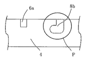
図4〜図5に示すように、外枠材4には、前述した内枠材2のピン部8aに対応する位置に、外枠材4の上面と内側面に向かって開口する溝状のピン受け部8bを設けてある。このピン受け部8bの幅や深さは特に限定されず、前述したピン部8aのサイズに応じて適宜選択することができる。図6に示すように、ピン受け部8bは側面への開口がL字形状であることが好ましい。また、当該開口はT字形状(図示せず)にすることも好ましい。そのようなL字形状またはT字形状を採用することにより、作業者が内枠材2を回動させる際の操作性が安定する。すなわち、内枠材2を回動させて持ち上げたときには外れにくくなり、元の状態に戻したときには外枠材4から内枠材2の取り外しが容易になる。 As shown in FIGS. 4 to 5, the
また、図4〜図5に示すように、外枠材4には、その上面と内側面に向かって開口する複数の回動固定版(回動固定手段)の嵌め込み溝6aが形成されている。この嵌め込み溝6aは、内枠材2を回動させて所定の角度に固定するものであり、通常、外枠材4の中心軸に対して対象となる位置に、対になるように複数設けられている。嵌め込み溝6aの本数は、通常3〜7本であり、好ましくは4〜6本である。嵌め込み溝6aの長さや幅は特に限定されず、後述する回動固定板(回動固定手段)6bのサイズに応じて適宜選択することができる。 Further, as shown in FIGS. 4 to 5, the
前記外枠材4は下面の四隅に脚部5を有することが好ましい。この脚部5を設けることにより、回動式枠材セット1の作業者の操作性が向上する。脚部5の長さは特に限定されず、通常、10〜20cmの範囲である。また、作業者の体格や姿勢に応じて、長さ(高さ)調整が可能な脚部を好ましく採用することができる。脚部5の材質、断面形状、サイズ(太さ)なども特に限定されないが、外観性の観点からは内枠材2および外枠材4と同じ材質にすることが好ましい。 The
(その他の部材)
図7に示すように、基布の張設手段である円形枠材3は、内枠材2の凹部3cに当接させて嵌め込んだ後に、円形枠材の押さえ部材3bにより上方から固定される。また、内枠材2の下面には円形枠材の支持部材7が架け渡してあり、円形枠材3を下方から支持している。円形枠材の押さえ部材3b及び支持部材7は断面方形の棒状に形成されている。それらの本数は特に限定されないが、通常、それぞれ2本である。(Other parts)
As shown in FIG. 7, the
円形枠材の押さえ部材3bの端部近傍にはマグネット(図示せず)が埋め込まれており、内枠材2の上面の対応する部位にもマグネット(図示せず)が埋め込まれているので、前記押さえ部材3bの内枠材2への着脱、換言すれば、円形枠材の着脱が容易になっている。また、円形枠材の支持部材7は内枠材2の下面にネジ止めされており、このネジ(図示せず)の締め具合を加減することにより、円形枠材へ異なる布厚の基布を張設する場合にも容易に対応できるようになっている。 A magnet (not shown) is embedded near the end of the holding
前述したように、外枠材4には、その上面と内側面に向かって開口する複数の回動固定版(回動固定手段)の嵌め込み溝6aが形成されており、その溝部に嵌め込んで使用する部材が回動固定板6bである。この回動固定板6bは内枠材2の回動角度(傾き角度)を調整する機能を有している。外枠材4の上面に形成されている嵌め込み溝6aの本数は、通常3〜7本であり、刺繍やキルティングを行う作業者は回動固定板6bの嵌め込み位置を適宜選択することにより、内枠材2を好みの傾き角度に調整することができる。 As described above, the
1 回動式枠材セット
2 内枠材
3 円形枠材(基布張設手段)
3a 円形枠材の締付け金具
3b 円形枠材の押さえ部材
3c 内枠材と円形枠材とが当接する凹部
4 外枠材
5 脚部
6a 回動固定板(回動固定手段)の嵌め込み溝
6b 回動固定板(回動固定手段)
7 円形枠材の支持部材
8a 回動軸のピン部
8b 回動軸のピン受け部
X−X 回動軸線
Y−Y 回動軸線
Z−Z 中心軸線1 Rotating frame material set 2
3a Tightening metal fittings for
7 Support member of
Claims (6)
前記内枠材および外枠材の一組の隣接する対向辺の間に設けられた回動軸を介して、前記内枠材は前記外枠材の平面から上方向または下方向に回動可能であり、前記内枠材を回動軸を支点として起こした際に、前記内枠材を前記外枠材に当接させて、起こした状態を保持するように形成されており、前記回動軸として前記内枠材の外周側端部から前記外枠材に向かって突出する一対のピン部と、前記外枠材の上面側端部の前記ピン部と対向する位置に、前記ピン部を受けるために開口する溝状のピン受け部とを有し、
前記張設手段は前記内枠材の内側に設けられた2層構造体の枠材であることを特徴とする回動式枠材セット。A flat square inner frame material having a means for attaching a base cloth and a flat square outer frame material which is opposed to the entire outer peripheral side of the inner frame material and supports the inner frame material are provided.
The inner frame material can rotate upward or downward from the plane of the outer frame material via a rotation shaft provided between the inner frame material and a set of the outer frame material adjacent facing sides. der is, when the inner frame member caused the rotation shaft as a fulcrum, the inner frame member is brought into contact with the outer frame member is formed so as to hold the state of raised was, the times A pair of pin portions projecting from the outer peripheral side end portion of the inner frame material toward the outer frame material as a moving axis, and the pin portion at a position facing the pin portion of the upper surface side end portion of the outer frame material. It has a groove-shaped pin receiving part that opens to receive
The stretched means revolvable frame member set, wherein the frame member der Rukoto of 2-layer structure provided on the inner side of the inner frame member.
前記内枠材は、その外周側端部から前記外枠材に向かって突出する二対のピン部を有し、
前記外枠材は、その上面側端部の前記ピン部と対向する位置に、前記内枠材を下支するピン受け部を有し、
前記ピン受け部は、前記外枠材の上面と内側面に向かって開口する溝状のピン受け部であり、
前記内枠材は、対向する一対のピン部を回動軸として、前記外枠材の平面から上方向に回動可能であり、
前記基布の張設手段として前記内枠材の内側に設けられた2層構造体の枠材を有することを特徴とする回動式枠材セット。A flat square inner frame material having a means for attaching a base cloth and a flat square outer frame material which is opposed to the entire outer peripheral side of the inner frame material and supports the inner frame material are provided.
The inner frame material has two pairs of pin portions protruding from the outer peripheral side end portion toward the outer frame material.
The outer frame material has a pin receiving portion that supports the inner frame material at a position facing the pin portion at the upper end side end portion thereof.
The pin receiving portion is a groove-shaped pin receiving portion that opens toward the upper surface and the inner side surface of the outer frame material.
The inner frame member has a pair of pin portions opposite the pivot axis, Ri pivotally der upwardly from the plane of the outer frame member,
Revolvable frame member set according to claim Rukoto that have a frame member of the two-layer structure provided on the inner side of the inner frame member as tensioned means of the base fabric.
Priority Applications (1)
| Application Number | Priority Date | Filing Date | Title |
|---|---|---|---|
| JP2020019218A JP6829532B1 (en) | 2020-01-22 | 2020-01-22 | Rotating frame material set |
Applications Claiming Priority (1)
| Application Number | Priority Date | Filing Date | Title |
|---|---|---|---|
| JP2020019218A JP6829532B1 (en) | 2020-01-22 | 2020-01-22 | Rotating frame material set |
Publications (2)
| Publication Number | Publication Date |
|---|---|
| JP6829532B1 true JP6829532B1 (en) | 2021-02-10 |
| JP2021116511A JP2021116511A (en) | 2021-08-10 |
Family
ID=74529708
Family Applications (1)
| Application Number | Title | Priority Date | Filing Date |
|---|---|---|---|
| JP2020019218A Active JP6829532B1 (en) | 2020-01-22 | 2020-01-22 | Rotating frame material set |
Country Status (1)
| Country | Link |
|---|---|
| JP (1) | JP6829532B1 (en) |
-
2020
- 2020-01-22 JP JP2020019218A patent/JP6829532B1/en active Active
Also Published As
| Publication number | Publication date |
|---|---|
| JP2021116511A (en) | 2021-08-10 |
Similar Documents
| Publication | Publication Date | Title |
|---|---|---|
| US3906648A (en) | Portable needlecraft support | |
| US4598488A (en) | Embroidery frame | |
| JP6155901B2 (en) | Embroidery frame and sewing machine | |
| US6298800B1 (en) | Embroidery apparatus | |
| JP2015010287A (en) | Embroidery frame and sewing machine | |
| JPH10273871A (en) | Hat frame device | |
| US3098280A (en) | Art needlework frame | |
| US4827638A (en) | Artwork support apparatus | |
| JP6829532B1 (en) | Rotating frame material set | |
| US6142459A (en) | Utility workstation | |
| DE2954652C2 (en) | ||
| US10612173B2 (en) | Hopping foot for a maneuverable quilting machine | |
| JPH05123468A (en) | Embroidery frame | |
| JPH10273872A (en) | Hat frame device | |
| US4364494A (en) | Smock gathering apparatus | |
| JP3394893B2 (en) | Hat frame device | |
| JP2570675Y2 (en) | Clip for clamping work cloth | |
| US6839992B1 (en) | Quilting frame apparatus | |
| JP3115467U (en) | Hoop holder | |
| US4410114A (en) | Combined tool for needlework | |
| US20240117540A1 (en) | Quilting table and method of using same | |
| JPS6140790Y2 (en) | ||
| JPH08232158A (en) | Hat frame for sewing machine | |
| US6655305B2 (en) | Apparatus for the embroidery of surface-shaped sewing material on a column-type, or free arm-type, sewing machine including distance adapter | |
| JPH08232155A (en) | Hat frame for sewing machine |
Legal Events
| Date | Code | Title | Description |
|---|---|---|---|
| A871 | Explanation of circumstances concerning accelerated examination |
Free format text: JAPANESE INTERMEDIATE CODE: A871 Effective date: 20200122 |
|
| A975 | Report on accelerated examination |
Free format text: JAPANESE INTERMEDIATE CODE: A971005 Effective date: 20200316 |
|
| A131 | Notification of reasons for refusal |
Free format text: JAPANESE INTERMEDIATE CODE: A131 Effective date: 20200714 |
|
| A521 | Request for written amendment filed |
Free format text: JAPANESE INTERMEDIATE CODE: A523 Effective date: 20200914 |
|
| TRDD | Decision of grant or rejection written | ||
| A01 | Written decision to grant a patent or to grant a registration (utility model) |
Free format text: JAPANESE INTERMEDIATE CODE: A01 Effective date: 20201208 |
|
| R150 | Certificate of patent or registration of utility model |
Ref document number: 6829532 Country of ref document: JP Free format text: JAPANESE INTERMEDIATE CODE: R150 |
|
| S531 | Written request for registration of change of domicile |
Free format text: JAPANESE INTERMEDIATE CODE: R313531 |
|
| R350 | Written notification of registration of transfer |
Free format text: JAPANESE INTERMEDIATE CODE: R350 |
|
| R250 | Receipt of annual fees |
Free format text: JAPANESE INTERMEDIATE CODE: R250 |