JP6828655B2 - Own vehicle position estimation device - Google Patents
Own vehicle position estimation device Download PDFInfo
- Publication number
- JP6828655B2 JP6828655B2 JP2017203728A JP2017203728A JP6828655B2 JP 6828655 B2 JP6828655 B2 JP 6828655B2 JP 2017203728 A JP2017203728 A JP 2017203728A JP 2017203728 A JP2017203728 A JP 2017203728A JP 6828655 B2 JP6828655 B2 JP 6828655B2
- Authority
- JP
- Japan
- Prior art keywords
- vehicle
- lane marking
- image
- distance
- unit
- Prior art date
- Legal status (The legal status is an assumption and is not a legal conclusion. Google has not performed a legal analysis and makes no representation as to the accuracy of the status listed.)
- Active
Links
Images


Description
本発明は、自車位置推定装置に関する。 The present invention relates to a vehicle position estimation device.
従来、自車位置推定装置に関する技術文献として、特開2015−194397号公報が知られている。この公報には、地図情報と車両周囲の撮像画像とから現時刻における車両の予測位置を検出する車両位置検出装置であって、地図情報に含まれる複数の地図線分(白線など)の位置情報と、車両周囲の撮像画像から検出して鳥瞰変換などを行なった複数の線分の位置とに基づいて、地図線分と撮像された線分との対応する組を求め、対応する地図線分と線分とが一致するように車両の予測位置の更新(検出)を行う装置が記載されている。 Conventionally, Japanese Patent Application Laid-Open No. 2015-194397 is known as a technical document relating to a vehicle position estimation device. This publication is a vehicle position detection device that detects the predicted position of the vehicle at the current time from the map information and the captured image around the vehicle, and the position information of a plurality of map line segments (white lines, etc.) included in the map information. Based on the position of a plurality of line segments detected from the captured image around the vehicle and subjected to bird's-eye view conversion, the corresponding set of the map line segment and the captured line segment is obtained, and the corresponding map line segment is obtained. A device that updates (detects) the predicted position of the vehicle so that the line segment and the line segment match is described.
ところで、画像を利用した自車位置推定においては、自車位置推定の基準となる道路の区画線をカメラに写る縁石や隣接車線の他車両のボディの横線と誤ってマッチング(照合)するおそれが存在する。この場合、自車位置を適切に推定できなくなるため問題がある。 By the way, in the estimation of the position of the own vehicle using the image, there is a risk that the lane marking of the road, which is the standard for estimating the position of the own vehicle, is erroneously matched (matched) with the curbstone captured by the camera or the horizontal line of the body of another vehicle in the adjacent lane. Exists. In this case, there is a problem because the position of the own vehicle cannot be estimated appropriately.
そこで、本技術分野では、自車位置を適切に推定することができる自車位置推定装置を提供することが望まれている。 Therefore, in the present technical field, it is desired to provide an own vehicle position estimation device capable of appropriately estimating the own vehicle position.
上記課題を解決するため、本発明の一態様は、車両の地図上の自車位置を推定する自車位置推定装置であって、道路の区画線の位置情報を含む地図情報を記憶している地図データベースと、車両の周囲を撮像するカメラの撮像画像に基づいて、車両の周囲の区画線を認識する区画線認識部と、車両のレーダセンサの検出結果に基づいて、車両の周囲の物体を認識する物体認識部と、区画線認識部の認識した区画線と地図情報に含まれる区画線の位置情報とに基づいて、車両の自車位置を推定する自車位置推定部と、物体と区画線との距離が距離閾値以上であるか否かを判定する距離判定部と、を備え、区画線認識部は、撮像画像に物体の画像が含まれる場合において、物体と区画線との距離が距離閾値以上であると判定されたときに、物体に対応する画像情報を除外して車両の周囲の区画線の認識を行い、距離判定部により物体と区画線との距離が距離閾値未満であると判定されたときには物体に対応する画像情報を除外せずに車両の周囲の区画線の認識を行う。 In order to solve the above problems, one aspect of the present invention is a self-vehicle position estimation device that estimates the self-vehicle position on a vehicle map, and stores map information including position information of road lane markings. Based on the map database and the captured image of the camera that captures the surroundings of the vehicle, the lane marking recognition unit that recognizes the lane markings around the vehicle, and the objects around the vehicle based on the detection results of the vehicle radar sensor. The own vehicle position estimation unit that estimates the vehicle's own vehicle position based on the recognized object recognition unit, the division line recognized by the division line recognition unit, and the position information of the division line included in the map information, and the object and division. A distance determination unit for determining whether or not the distance to the line is equal to or greater than the distance threshold is provided, and the lane marking unit recognizes the distance between the object and the lane line when the captured image includes an image of the object. when it is determined that the distance threshold or more, by excluding image information corresponding to the object have line recognition of a lane mark around the vehicle, the distance between the object and the lane mark by the distance determining section is less than the distance threshold value When it is determined that there is, the lane marking around the vehicle is recognized without excluding the image information corresponding to the object .
本発明の一態様に係る自車位置推定装置によれば、自車位置を適切に推定することができる。 According to the own vehicle position estimation device according to one aspect of the present invention, the own vehicle position can be appropriately estimated.
以下、本発明の実施形態について図面を参照して説明する。 Hereinafter, embodiments of the present invention will be described with reference to the drawings.
図1に示す一実施形態に係る自車位置推定装置100は、乗用車などの車両に搭載され、当該車両の地図上の位置である自車位置を推定する装置である。自車位置推定装置100は、車載のカメラにより撮像した車両の周囲の撮像画像から、車両の走行する走行車線(道路)の区画線を認識し、地図情報に含まれる区画線の位置情報を利用して自車位置を推定する。区画線には、車道通行帯境界線、車線境界線、中央線などが含まれる。
The own vehicle
自車位置推定装置100は、車載のレーダセンサの検出結果から車両の周囲の壁や縁石などの物体を認識し、物体に対応する画像情報を除外して区画線の認識を行うことで、壁や縁石を誤って区画線として認識する可能性を低減する。物体には、壁、ガードレール、建物などの静止物体の他、歩行者、自転車、他車両などの移動物体が含まれる。
The own vehicle
[自車位置推定装置の構成]
図1に示すように、自車位置推定装置100は、装置を統括的に管理するECU[Electronic Control Unit]10を備えている。ECU10は、CPU[Central Processing Unit]、ROM[Read Only Memory]、RAM[Random Access Memory]、CAN[Controller Area Network]通信回路などを有する電子制御ユニットである。ECU10では、例えば、ROMに記憶されているプログラムをRAMにロードし、RAMにロードされたプログラムをCPUで実行することにより各種の機能を実現する。ECU10は、複数の電子ユニットから構成されていてもよい。
[Configuration of own vehicle position estimation device]
As shown in FIG. 1, the own vehicle
ECU10は、GPS受信部1、カメラ2、レーダセンサ3、内部センサ4、及び地図データベース5に接続されている。
The ECU 10 is connected to a GPS receiving unit 1, a camera 2, a radar sensor 3, an internal sensor 4, and a
GPS受信部1は、3個以上のGPS衛星から信号を受信することにより、車両の位置(例えば車両の緯度及び経度)を測定する。GPS受信部1は、測定した車両の位置情報をECU10へ送信する。
The GPS receiving unit 1 measures the position of the vehicle (for example, the latitude and longitude of the vehicle) by receiving signals from three or more GPS satellites. The GPS receiving unit 1 transmits the measured position information of the vehicle to the
カメラ2は、車両の周囲を撮像する撮像機器である。カメラ2は、一例として、車両のフロントガラスの裏側に設けられ、車両の前方を撮像する。カメラ2は、車両の前方の他、車両の後方を撮像するように設けられていてもよく、車両の側方を撮像するように設けられていてもよい。カメラ2は、撮像した車両の周囲の撮像画像をECU10へ送信する。なお、カメラ2は、単眼カメラであってもよく、ステレオカメラであってもよい。
The camera 2 is an imaging device that images the surroundings of the vehicle. As an example, the camera 2 is provided on the back side of the windshield of the vehicle and images the front of the vehicle. The camera 2 may be provided so as to image the rear of the vehicle as well as the front of the vehicle, or may be provided to image the side of the vehicle. The camera 2 transmits the captured image of the surroundings of the vehicle to the
レーダセンサ3は、電波(例えばミリ波)又は光を利用して車両の周囲の物体を検出する検出機器である。レーダセンサ3には、例えば、ミリ波レーダ又はライダー[LIDAR:Light Detection and Ranging]が含まれる。レーダセンサは、電波又は光を車両の周囲に送信し、物体によって反射された電波又は光を受信することで車両の周囲の物体を検出する。レーダセンサ3は、物体の検出情報をECU10へ送信する。
The radar sensor 3 is a detection device that detects an object around a vehicle by using radio waves (for example, millimeter waves) or light. The radar sensor 3 includes, for example, a millimeter-wave radar or a lidar [LIDAR: Light Detection and Ranging]. The radar sensor transmits radio waves or light to the surroundings of the vehicle, and detects objects around the vehicle by receiving radio waves or light reflected by the object. The radar sensor 3 transmits the detection information of the object to the
内部センサ4は、車両の走行状態を検出する検出機器である。内部センサ4は、車速センサ、加速度センサ、及びヨーレートセンサを含む。車速センサは、車両の速度を検出する検出器である。車速センサとしては、例えば、車両の車輪又は車輪と一体に回転するドライブシャフトなどに対して設けられ、車輪の回転速度を検出する車輪速センサが用いられる。車速センサは、検出した車速情報(車輪速情報)をECU10に送信する。
The internal sensor 4 is a detection device that detects the traveling state of the vehicle. The internal sensor 4 includes a vehicle speed sensor, an acceleration sensor, and a yaw rate sensor. The vehicle speed sensor is a detector that detects the speed of the vehicle. As the vehicle speed sensor, for example, a wheel speed sensor provided on a wheel of a vehicle or a drive shaft that rotates integrally with the wheel or the like and detects the rotation speed of the wheel is used. The vehicle speed sensor transmits the detected vehicle speed information (wheel speed information) to the
加速度センサは、車両の加速度を検出する検出器である。加速度センサは、例えば、車両の前後方向の加速度を検出する前後加速度センサと、車両の横加速度を検出する横加速度センサとを含んでいる。加速度センサは、例えば、車両の加速度情報をECU10に送信する。ヨーレートセンサは、車両の重心の鉛直軸周りのヨーレート(回転角速度)を検出する検出器である。ヨーレートセンサとしては、例えばジャイロセンサを用いることができる。ヨーレートセンサは、検出した車両のヨーレート情報をECU10へ送信する。なお、自車位置推定装置100において内部センサ4は必須ではない。
An acceleration sensor is a detector that detects the acceleration of a vehicle. The acceleration sensor includes, for example, a front-rear acceleration sensor that detects the acceleration in the front-rear direction of the vehicle and a lateral acceleration sensor that detects the lateral acceleration of the vehicle. The acceleration sensor transmits, for example, vehicle acceleration information to the
地図データベース5は、地図情報を記憶するデータベースである。地図データベース5は、例えば、車両に搭載されたHDD[Hard Disk Drive]内に形成されている。地図情報には、道路の位置情報、道路形状の情報(例えばカーブ、直線部の種別、カーブの曲率など)、区画線の位置情報、及び壁やガードレールなどの構造物(静止物体)の位置情報などが含まれる。なお、地図データベース5は、車両と通信可能なサーバに記憶されていてもよい。
The
次に、ECU10の機能的構成について説明する。ECU10は、測定位置取得部11、物体認識部12、距離判定部13、区画線認識部14、及び自車位置推定部15を有している。なお、ECU10の機能の一部は、車両と通信可能なサーバにおいて実行される態様であってもよい。
Next, the functional configuration of the
測定位置取得部11は、GPS受信部1の測定した車両の位置情報に基づいて、車両の地図上の位置である測定位置を取得する。測定位置取得部11は、内部センサ4の検出結果に基づいて、車両の車速の履歴(或いは車輪の回転数の履歴)及び車両のヨーレートの履歴などから車両の測定位置を取得してもよい。言い換えれば、測定位置取得部11は、周知の手法を用いて、いわゆるオドメトリにより車両の測定位置を取得してもよい。
The measurement
物体認識部12は、レーダセンサ3の検出結果(物体の検出情報)に基づいて、車両の周囲の物体を認識する。物体認識部12は、例えば、レーダセンサ3の検出点(反射点)を周知の手法によりグルーピングし、予め用意された物体モデルと照合することにより物体の認識を行う。物体モデルには、車両(四輪車、二輪車)のモデル、大型車両のモデル、歩行者のモデル、壁のモデル、ガードレールのモデルなどが含まれる。
The
物体認識部12は、レーダセンサ3の検出結果に基づいて、車両に対する物体の位置を認識する。また、物体認識部12は、レーダセンサ3の検出結果に基づいて、物体のうち車両に最も近い面(又は点)を認識する。
The
距離判定部13は、物体と区画線との距離が距離閾値以上であるか否かを判定する。距離閾値は予め設定された値である。距離判定部13は、例えば、レーダセンサ3の検出結果に基づいて、もしくは現在より1ステップ以上前の車両位置から内部センサ4の検出結果により予測される現在の車両位置周辺の地図情報に基づいて、車両に対する区画線の位置を認識する。レーダセンサ3の検出結果を利用した白線認識は周知の手法である。距離判定部13は、物体認識部12の認識した物体の位置と区画線の位置とに基づいて、物体と区画線との距離が距離閾値以上であるか否かを判定する。物体と区画線との距離とは、最短距離である。
The
区画線認識部14は、カメラ2の撮像画像に基づいて、車両の周囲の区画線を認識(画像認識)する。区画線認識部14は、カメラ2の撮像画像を周知の投影変換によって路面画像に変換し、路面画像から車両の周囲の区画線の認識を行う。
The
ここで、図2(a)は、車載のカメラの撮像画像Gを示す図である。図2(a)に、壁W、車両の左側の区画線L1、車両の右側の区画線L2、隣接車線の区画線L3を示す。区画線L1及び区画線L2は車両の走行車線を形成し、区画線L2及び区画線L3は走行車線に隣接する隣接車線を形成している。 Here, FIG. 2A is a diagram showing an image G captured by an in-vehicle camera. FIG. 2A shows the wall W, the lane marking L1 on the left side of the vehicle, the lane marking L2 on the right side of the vehicle, and the lane marking L3 on the adjacent lane. The lane marking L1 and the lane marking L2 form a traveling lane of the vehicle, and the lane marking L2 and the lane marking L3 form an adjacent lane adjacent to the traveling lane.
また、図2(b)は、路面画像を説明するための図である。図2(b)に、車両(自車両)Mと路面画像のうち図2(a)の撮像画像に対応する画像領域Aとを示す。画像領域Aは、図2(a)の撮像画像Gを投影変換して得られた画像領域である。この画像領域Aを車両Mの車速に応じて直前に生成された路面画像に重ね合わせる(画像照合を行う)ことで路面画像が延長される。ここでは説明を容易にするため区画線L3を省略する。 Further, FIG. 2B is a diagram for explaining a road surface image. FIG. 2B shows a vehicle (own vehicle) M and an image region A corresponding to the captured image of FIG. 2A among the road surface images. The image area A is an image area obtained by projecting and converting the captured image G of FIG. 2 (a). The road surface image is extended by superimposing the image area A on the road surface image generated immediately before according to the vehicle speed of the vehicle M (performing image matching). Here, the lane marking L3 is omitted for the sake of simplicity.
画像照合は、例えば、位相限定相関法により大域的な位置合わせを行い、その後に最小二乗マッチングによって区画線などを含む線分を照合させることで高精度に局所的な位置合わせを行う。なお、高い精度の画像照合を行うため、直前の路面画像だけではなく、更に過去の路面画像を合わせて用いてもよい。路面画像の変換(生成)は、上述した手法に限定されず、周知の手法を採用することができる。 In image collation, for example, global alignment is performed by a phase-limited correlation method, and then line segments including lane markings and the like are collated by least squares matching to perform local alignment with high accuracy. In addition, in order to perform image matching with high accuracy, not only the immediately preceding road surface image but also the past road surface image may be used together. The conversion (generation) of the road surface image is not limited to the above-mentioned method, and a well-known method can be adopted.
区画線認識部14は、路面画像に基づいて区画線の位置を認識する。区画線認識部14は、パターンマッチングなどの周知の画像認識処理により、路面画像から区画線の画像認識を行うことで、車両Mに対する区画線の位置を認識する。区画線認識部14は、路面画像だけではなく、距離判定部13においてレーダセンサ3の検出結果から認識された区画線の位置も利用して区画線の位置認識を行ってもよい。
The
また、区画線認識部14は、カメラ2の撮像画像に物体が含まれる場合、物体に対応する画像情報は区画線の認識のノイズとなることから、区画線の認識において物体に対応する画像情報を除外(マスク)する。
Further, when the image captured by the camera 2 includes an object, the lane marking
まず、区画線認識部14は、カメラ2の撮像画像に基づいて、撮像画像に物体が含まれるか否かを判定する。区画線認識部14は、パターンマッチングなどの周知の画像認識処理によって、撮像画像に物体が含まれるか否かを判定する。区画線認識部14は、物体認識部12による物体の認識結果を利用して上記の判定を行ってもよい。
First, the lane marking
区画線認識部14は、撮像画像に物体が含まれると判定した場合において、距離判定部13により当該物体と区画線との距離が距離閾値以上であると判定されたとき、当該物体に対応する画像情報を除外して車両Mの周囲の区画線を認識する。これにより、区画線認識部14は、区画線の認識においてノイズの原因となる壁や他車両などの画像情報を予め除外することで、壁や壁の模様、他車両のボディの横線や凹凸などを区画線として誤認識することを避けることができ、区画線の認識における不要な演算も減らすことができる。
When the
一方で、区画線認識部14は、撮像画像に物体が含まれると判定した場合において、距離判定部13により当該物体と区画線との距離が距離閾値未満であると判定されたとき、当該物体に対応する画像情報を除外せずに、車両Mの周囲の区画線を認識する。区画線認識部14は、物体と区画線との距離が近すぎる場合、撮像画像において物体に対応する画像情報を除外すると区画線に対応する画像情報の一部も除外してしまう可能性があることから、当該物体に対応する画像情報を除外せずに区画線の認識を行う。
On the other hand, when the
具体的に、図3(a)は、車両の周囲に壁を検出した場合を示す図である。図3(a)に、車両Mのレーダセンサ3の検出範囲B、壁Wのうちレーダセンサ3に検出されている壁部分Wa、壁部分Waと区画線L1との距離Dwを示す。 Specifically, FIG. 3A is a diagram showing a case where a wall is detected around the vehicle. FIG. 3A shows the detection range B of the radar sensor 3 of the vehicle M, the wall portion Wa of the wall W detected by the radar sensor 3, and the distance Dw between the wall portion Wa and the lane marking L1.
図3に示す状況において、区画線認識部14は、画像領域Aに壁Wの一部が含まれていることから、カメラ2の撮像画像に壁W(物体)が含まれていると判定する。距離判定部13は、レーダセンサ3の検出結果に基づいて、壁部分Waと区画線L1との距離Dw(すなわち壁Wと壁Wに最も近い区画線L1との距離Dw)を認識する。
In the situation shown in FIG. 3, the division
区画線認識部14は、距離判定部13により壁部分Waと区画線L1との距離Dwが距離閾値以上であると判定された場合、路面画像から壁Wに対応する画像情報を除外して、区画線の認識を行う。図3(b)は、壁Wに対応する画像情報の除外を説明するための図である。図3(b)において、除外対象として壁Wを含む外側画像領域Ex1を示す。外側画像領域Ex1は、路面画像において壁Wに対応する画像情報である。区画線認識部14は、壁Wに対応する画像情報として外側画像領域Ex1を除外する。
When the
なお、図3(b)に示すように、区画線認識部14は、路面画像において車両Mから見て物体より外側の領域には認識すべき区画線が映っていないと考えられることから、車両Mを基準として壁W(物体)より外側の領域全てを区画線の認識の処理対象から除外する外側画像領域Ex1とする。なお、外側画像領域Ex1は壁Wを含む領域であれば限定されない。
As shown in FIG. 3B, since it is considered that the
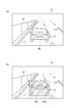
次に、図4(a)は、隣接車線の他車両を検出した場合を示す図である。図4(a)に、隣接車線を走行する他車両N1、他車両N1と区画線L2との距離Dnを示す。他車両N1は、カメラ2の撮像画像に含まれ、レーダセンサ3によって検出されている。 Next, FIG. 4A is a diagram showing a case where another vehicle in an adjacent lane is detected. FIG. 4A shows the distance Dn between the other vehicle N1 and the other vehicle N1 traveling in the adjacent lane and the lane marking L2. The other vehicle N1 is included in the captured image of the camera 2 and is detected by the radar sensor 3.
図4(a)に示す状況において、区画線認識部14は、画像領域Aに他車両N1の一部が含まれていることから、カメラ2の撮像画像に他車両N1(物体)が含まれていると判定する。距離判定部13は、レーダセンサ3の検出結果に基づいて、他車両N1と区画線L2との距離Dnを認識する。
In the situation shown in FIG. 4A, since the lane marking
区画線認識部14は、距離判定部13により他車両N1と区画線L1との距離Dnが距離閾値以上であると判定された場合、路面画像から他車両N1に対応する画像情報を除外して、区画線の認識を行う。図4(b)は、他車両N1に対応する画像情報の除外を説明するための図である。図4(b)において、除外対象として他車両N1を含む外側画像領域Ex2を示す。外側画像領域Ex2は、路面画像において他車両N1に対応する画像情報である。外側画像領域Ex2は、車両Mを基準として車両Mの車幅方向で他車両N1より外側の領域全てを含んでいる。区画線認識部14は、他車両N1に対応する画像情報として外側画像領域Ex2を除外する。なお、外側画像領域Ex2は他車両N1を含む領域であれば限定されない。
When the
区画線認識部14は、路面画像に変換する前に、カメラ2の撮像画像から物体に対応する画像情報を除外してもよい。図5(a)は、先行車が含まれる場合の撮像画像Gを示す図である。図5(a)に先行車N2を示す。
The
図5(b)は、先行車N2に対応する画像情報の除外を説明するための図である。図5(b)に示すように、区画線認識部14は、カメラ2の撮像画像Gにおける先行車N2に対応する画像領域Ex3を除外(マスク)する。区画線認識部14は、先行車N2に対応する画像情報として画像領域Ex3を除外する。
FIG. 5B is a diagram for explaining exclusion of image information corresponding to the preceding vehicle N2. As shown in FIG. 5B, the lane marking
区画線認識部14は、先行車N2に対応する画像領域Ex3を除外した撮像画像Gを路面画像に変換して区画線の認識を行うことで、先行車のボディの凹凸、模様などをノイズとして含む路面画像を生成することを避けると共に、区画線の認識における不要な演算を減らすことができる。
The
自車位置推定部15は、測定位置取得部11の取得した車両Mの測定位置と、区画線認識部14による区画線の認識結果と、地図データベース5の地図情報とに基づいて、車両Mの地図上の位置である自車位置の推定を行う。具体的に、自車位置推定部15は、測定位置取得部11の取得した車両Mの測定位置に基づいて、地図情報において照合対象となる区画線を抽出する(地図上で照合対象となるエリアを絞り込む)。自車位置推定部15は、区画線認識部14の認識した車両Mに対する区画線の位置と、地図情報から抽出した区画線の地図上の位置情報とに基づいて、車両Mの自車位置を推定する。
The own vehicle
なお、区画線を用いた自車位置の推定方法は、上述した方法に限定されず、周知の手法を採用することができる。自車位置推定部15は、直前に推定した自車位置を用いて、地図情報における照合対象となる区画線を抽出してもよく、直前に抽出した区画線を用いて地図情報から今回の自車位置推定に用いる区画線を抽出してもよい。
The method of estimating the position of the own vehicle using the lane marking is not limited to the above-mentioned method, and a well-known method can be adopted. The own vehicle
[自車位置推定装置の自車位置推定処理]
以下、自車位置推定装置100の自車位置推定処理について図6を参照して説明する。図6は、自車位置推定処理を示すフローチャートである。図6に示すフローチャートは,例えば、車両Mの走行中に実行される。なお、測定位置取得部11による車両Mの測定位置の取得は随時行われているものとする。
[Own vehicle position estimation process of own vehicle position estimation device]
Hereinafter, the own vehicle position estimation process of the own vehicle
図6に示すように、自車位置推定装置100のECU10は、S10として、カメラ2の撮像画像及びレーダセンサ3の検出結果を取得する。
As shown in FIG. 6, the
S12において、ECU10は、物体認識部12により車両Mの周囲の物体を認識する。物体認識部12は、例えば、レーダセンサ3の検出点(反射点)を周知の手法によりグルーピングし、予め用意された物体モデルと照合することにより物体の認識を行う。物体認識部12は、レーダセンサ3の検出結果に基づいて、車両Mに対する物体の位置を認識する。
In S12, the
S14において、ECU10は、区画線認識部14によりカメラ2の撮像画像に物体が含まれるか否かを判定する。区画線認識部14は、カメラ2の撮像画像に周知の画像認識処理を行うことで撮像画像に物体が含まれるか否かを判定する。ECU10は、カメラ2の撮像画像に物体が含まれると判定されなかった場合(S12:NO)、S16に移行する。一方、ECU10は、カメラ2の撮像画像に物体が含まれると判定された場合(S12:YES)、S20に移行する。
In S14, the
S16において、ECU10は、区画線認識部14によりカメラ2の撮像画像を路面画像に投影変換する。区画線認識部14は、位相限定相関法や画像中の線分の最小二乗マッチングにより、撮像画像を投影変換して路面画像を生成する。
In S16, the
S18において、ECU10は、区画線認識部14により路面画像から車両Mの周囲の区画線を認識する。区画線認識部14は、パターンマッチングその他の周知の手法により、路面画像から区画線の画像認識を行うことで、車両Mに対する区画線の位置を認識する。その後、ECU10は、S26に移行する。
In S18, the
S20において、ECU10は、区画線認識部14によりカメラ2の撮像画像を路面画像に投影変換する。処理内容はS16と同じである。
In S20, the
S22において、ECU10は、距離判定部13により物体と区画線との距離が距離閾値以上であるか否かを判定する。距離判定部13は、例えば、レーダセンサ3の検出結果に基づいて物体の位置と車両Mに対する区画線の位置を認識することで上記判定を行う。ECU10は、物体と区画線との距離が距離閾値未満であると判定された場合(S22:NO)、物体に対応する画像情報を除外しないので、前述したS18に移行する。一方、ECU10は、物体と区画線との距離が距離閾値以上であると判定された場合(S22:YES)、S24に移行する。
In S22, the
S24において、ECU10は、区画線認識部14により物体に対応する画像情報を除外して車両Mの周囲の区画線を認識する。区画線認識部14は、路面画像から物体に対応する画像情報を除外し、残りの領域について区画線の認識を行う。区画線認識部14は、車両Mに対する区画線の位置を認識する。
In S24, the
S26において、ECU10は、自車位置推定部15により自車位置の推定を行う。自車位置推定部15は、測定位置取得部11の取得した車両Mの測定位置と、区画線認識部14による区画線の認識結果と、地図データベース5の地図情報とに基づいて、車両Mの地図上の位置である自車位置の推定を行う。自車位置推定部15は、区画線認識部14の認識した車両Mに対する区画線の位置と、測定位置を用いて地図情報から抽出した区画線の地図上の位置情報とに基づいて、車両Mの自車位置を推定する。
In S26, the
[自車位置推定装置の作用効果]
以上説明した一実施形態に係る自車位置推定装置100によれば、壁や他車両などの物体が撮像画像に含まれる場合には、物体に対応する画像情報を除外して区画線の認識を行うので、他車両のボディの横線などを誤って区画線として認識することが避けられ、自車位置を適切に推定することができる。
[Effect of own vehicle position estimation device]
According to the own vehicle
以上、本発明の好適な実施形態について説明したが、本発明は上述した実施形態に限定されるものではない。本発明は、上述した実施形態を始めとして、当業者の知識に基づいて種々の変更、改良を施した様々な形態で実施することができる。 Although the preferred embodiment of the present invention has been described above, the present invention is not limited to the above-described embodiment. The present invention can be carried out in various forms having various modifications and improvements based on the knowledge of those skilled in the art, including the above-described embodiment.
距離判定部13は、カメラ2がステレオカメラである場合、カメラ2の撮像情報(奥行方向の距離情報を含む)に基づいて、車両に対する物体の位置と車両に対する区画線の位置とを認識してもよい。距離判定部13は、地図情報に基づいて、物体と区画線との距離を認識してもよい。図3(a)に示す状況において、距離判定部13は、物体認識部12によって物体が壁Wであると認識された場合、地図情報に含まれる地図上の壁Wの位置情報と地図上の区画線L1の位置情報とに基づいて、物体と区画線との距離することができる。この場合の物体は、地図情報に位置情報が含まれている壁やガードレール、電柱などの静止物体である必要がある。
When the camera 2 is a stereo camera, the
自車位置推定装置100は、必ずしも距離判定部13を備える必要はない。この場合、区画線認識部14は、カメラ2の撮像画像に物体が含まれるときには、物体と区画線との距離に関わらず、物体に対応する画像情報を除外して区画線の認識を行う。
The own vehicle
区画線認識部14は、図3(a)及び図3(b)において説明した壁Wに対応する画像情報の除外、図4(a)及び図4(b)において説明した他車両N1に対応する画像情報の除外、図5(a)及び図5(b)において説明した先行車N2に対応する画像情報の除外の全てを行う必要はない。区画線認識部14は、何れか一つの画像情報の除外を行う態様であればよい。
The
区画線認識部14は、過去の区画線の認識結果に基づいて、現在(今回)の画像情報において区画線が存在する範囲を予測してもよい。この場合において、区画線認識部14は、画像情報のうち区画線が存在すると予測される範囲以外の画像情報を除外して、車両の周囲の区画線の認識を行うことができる。この態様は、車両の位置から一定距離以上継続する直線区間を車両が走行している場合など、車両の走行車線における区画線の位置の変動が少ない場合に有用である。
The
例えば、区画線認識部14は、1ステップ以前の時刻において認識した区画線と物体認識部12から得られる区画線情報と地図情報に含まれる区画線の位置情報とが一致する場合、上記時刻から現在時刻までの内部センサ4の検出結果に基づく車両の移動情報に基づいて予測した現在の車両位置における区画線の位置に対応する画像情報以外を除外することができる。
For example, when the
1…GPS受信部、2…カメラ、3…レーダセンサ、4…内部センサ、5…地図データベース、10…ECU、11…測定位置取得部、12…物体認識部、13…距離判定部、14…区画線認識部、15…自車位置推定部、100…自車位置推定装置。 1 ... GPS receiver, 2 ... camera, 3 ... radar sensor, 4 ... internal sensor, 5 ... map database, 10 ... ECU, 11 ... measurement position acquisition unit, 12 ... object recognition unit, 13 ... distance determination unit, 14 ... Section line recognition unit, 15 ... own vehicle position estimation unit, 100 ... own vehicle position estimation device.
Claims (1)
道路の区画線の位置情報を含む地図情報を記憶している地図データベースと、
前記車両の周囲を撮像するカメラの撮像画像に基づいて、前記車両の周囲の区画線を認識する区画線認識部と、
前記車両のレーダセンサの検出結果に基づいて、前記車両の周囲の物体を認識する物体認識部と、
前記区画線認識部の認識した前記区画線と前記地図情報に含まれる前記区画線の位置情報とに基づいて、前記車両の前記自車位置を推定する自車位置推定部と、
前記物体と前記区画線との距離が距離閾値以上であるか否かを判定する距離判定部と、
を備え、
前記区画線認識部は、前記撮像画像に前記物体の画像が含まれる場合において、前記距離判定部により前記物体と前記区画線との距離が距離閾値以上であると判定されたときに、前記物体に対応する画像情報を除外して前記車両の周囲の区画線の認識を行い、前記距離判定部により前記物体と前記区画線との距離が前記距離閾値未満であると判定されたときには前記物体に対応する画像情報を除外せずに前記車両の周囲の区画線の認識を行う、自車位置推定装置。 It is a vehicle position estimation device that estimates the vehicle position on the map of the vehicle.
A map database that stores map information including the location information of road lane markings,
A lane marking recognition unit that recognizes a lane marking around the vehicle based on an image captured by a camera that captures the surroundings of the vehicle.
An object recognition unit that recognizes objects around the vehicle based on the detection results of the vehicle radar sensor,
The own vehicle position estimation unit that estimates the own vehicle position of the vehicle based on the division line recognized by the division line recognition unit and the position information of the division line included in the map information.
A distance determination unit that determines whether or not the distance between the object and the division line is equal to or greater than the distance threshold value.
With
The division line recognition unit, in the case where the image of the object is included in the captured image, when the distance between the object and the lane mark by the distance determination unit is determined to be equal to or greater than the distance threshold value, the object wherein the object when a distance between the partition lines and the object is determined to be smaller than the distance threshold by a row have, the distance determining section recognizes demarcation line around the vehicle by excluding the image information corresponding to the A vehicle position estimation device that recognizes a lane marking around the vehicle without excluding the image information corresponding to the above .
Priority Applications (1)
| Application Number | Priority Date | Filing Date | Title |
|---|---|---|---|
| JP2017203728A JP6828655B2 (en) | 2017-10-20 | 2017-10-20 | Own vehicle position estimation device |
Applications Claiming Priority (1)
| Application Number | Priority Date | Filing Date | Title |
|---|---|---|---|
| JP2017203728A JP6828655B2 (en) | 2017-10-20 | 2017-10-20 | Own vehicle position estimation device |
Publications (2)
| Publication Number | Publication Date |
|---|---|
| JP2019078562A JP2019078562A (en) | 2019-05-23 |
| JP6828655B2 true JP6828655B2 (en) | 2021-02-10 |
Family
ID=66627638
Family Applications (1)
| Application Number | Title | Priority Date | Filing Date |
|---|---|---|---|
| JP2017203728A Active JP6828655B2 (en) | 2017-10-20 | 2017-10-20 | Own vehicle position estimation device |
Country Status (1)
| Country | Link |
|---|---|
| JP (1) | JP6828655B2 (en) |
Families Citing this family (5)
| Publication number | Priority date | Publication date | Assignee | Title |
|---|---|---|---|---|
| JP7173062B2 (en) * | 2020-01-23 | 2022-11-16 | トヨタ自動車株式会社 | Change point detection device and map information distribution system |
| WO2021208110A1 (en) * | 2020-04-18 | 2021-10-21 | 华为技术有限公司 | Method for determining lane line recognition abnormal event, and lane line recognition apparatus and system |
| JPWO2022071315A1 (en) * | 2020-09-30 | 2022-04-07 | ||
| JP2022139830A (en) * | 2021-03-12 | 2022-09-26 | 株式会社豊田自動織機 | Autonomous travelling vehicle |
| JP2022145014A (en) * | 2021-03-19 | 2022-10-03 | 株式会社豊田自動織機 | autonomous vehicle |
Family Cites Families (3)
| Publication number | Priority date | Publication date | Assignee | Title |
|---|---|---|---|---|
| JP4648697B2 (en) * | 2004-12-27 | 2011-03-09 | アイシン・エィ・ダブリュ株式会社 | Image recognition apparatus and method, and navigation apparatus |
| JP6380422B2 (en) * | 2016-02-05 | 2018-08-29 | トヨタ自動車株式会社 | Automated driving system |
| JP6604240B2 (en) * | 2016-03-08 | 2019-11-13 | アイシン・エィ・ダブリュ株式会社 | Automatic driving support device and computer program |
-
2017
- 2017-10-20 JP JP2017203728A patent/JP6828655B2/en active Active
Also Published As
| Publication number | Publication date |
|---|---|
| JP2019078562A (en) | 2019-05-23 |
Similar Documents
| Publication | Publication Date | Title |
|---|---|---|
| JP6828655B2 (en) | Own vehicle position estimation device | |
| JP6859927B2 (en) | Vehicle position estimation device | |
| US9669829B2 (en) | Travel lane marking recognition system | |
| JP6323402B2 (en) | In-lane travel control device, in-lane travel control method | |
| JP7074438B2 (en) | Vehicle position estimation device | |
| JP6626410B2 (en) | Vehicle position specifying device and vehicle position specifying method | |
| US11092442B2 (en) | Host vehicle position estimation device | |
| US11631257B2 (en) | Surroundings recognition device, and surroundings recognition method | |
| US20190073540A1 (en) | Vehicle control device, vehicle control method, and storage medium | |
| JP7143722B2 (en) | Vehicle position estimation device | |
| JP6520740B2 (en) | Object detection method, object detection device, and program | |
| US11042759B2 (en) | Roadside object recognition apparatus | |
| US20200130683A1 (en) | Collision prediction apparatus and collision prediction method | |
| US20170225681A1 (en) | Driving support apparatus, server, and non-transitory computer-readable medium | |
| JP2009181315A (en) | Object detection device | |
| US20160148059A1 (en) | Travel lane marking recognition apparatus | |
| WO2017013692A1 (en) | Travel lane determination device and travel lane determination method | |
| US20220309804A1 (en) | Vehicle control device, vehicle control method, and storage medium | |
| JP7182963B2 (en) | Moving body detection system and moving body detection method | |
| JP2020020690A (en) | Vehicle position estimating device | |
| US20220306150A1 (en) | Control device, control method, and storage medium | |
| JP2019196941A (en) | Own vehicle position estimating device | |
| US11867526B2 (en) | Map generation apparatus | |
| KR20220161905A (en) | Apparatus and Method for Controlling Vehicle Using Virtual Lane | |
| JP2023151308A (en) | Preceding vehicle determination method and preceding vehicle determination device |
Legal Events
| Date | Code | Title | Description |
|---|---|---|---|
| A621 | Written request for application examination |
Free format text: JAPANESE INTERMEDIATE CODE: A621 Effective date: 20191216 |
|
| A977 | Report on retrieval |
Free format text: JAPANESE INTERMEDIATE CODE: A971007 Effective date: 20200715 |
|
| A131 | Notification of reasons for refusal |
Free format text: JAPANESE INTERMEDIATE CODE: A131 Effective date: 20200721 |
|
| A521 | Written amendment |
Free format text: JAPANESE INTERMEDIATE CODE: A523 Effective date: 20200911 |
|
| TRDD | Decision of grant or rejection written | ||
| A01 | Written decision to grant a patent or to grant a registration (utility model) |
Free format text: JAPANESE INTERMEDIATE CODE: A01 Effective date: 20201222 |
|
| A61 | First payment of annual fees (during grant procedure) |
Free format text: JAPANESE INTERMEDIATE CODE: A61 Effective date: 20210104 |
|
| R151 | Written notification of patent or utility model registration |
Ref document number: 6828655 Country of ref document: JP Free format text: JAPANESE INTERMEDIATE CODE: R151 |