JP6826842B2 - Wind direction changing device and air conditioner equipped with this - Google Patents
Wind direction changing device and air conditioner equipped with this Download PDFInfo
- Publication number
- JP6826842B2 JP6826842B2 JP2016166313A JP2016166313A JP6826842B2 JP 6826842 B2 JP6826842 B2 JP 6826842B2 JP 2016166313 A JP2016166313 A JP 2016166313A JP 2016166313 A JP2016166313 A JP 2016166313A JP 6826842 B2 JP6826842 B2 JP 6826842B2
- Authority
- JP
- Japan
- Prior art keywords
- wind direction
- plate
- interlocking plate
- substrate
- longitudinal direction
- Prior art date
- Legal status (The legal status is an assumption and is not a legal conclusion. Google has not performed a legal analysis and makes no representation as to the accuracy of the status listed.)
- Active
Links
Images


Description
本発明は、風向変更装置及びこれを備えた空気調和機に関する。 The present invention relates to a wind direction changing device and an air conditioner including the same.
特許文献1には、空気調和機の吹出口に設置され、風向を左右に変更するための風向変更装置が開示されている。
しかしながら、特許文献1に開示の風向変更装置では、次のような問題が考えられる。この問題について、図20及び図21を参照して説明する。
However, the wind direction changing device disclosed in
図20は参考例として示す、空気調和機の吹出口に設置された風向変更装置の概略的構成を示す上面図であり、図21は図20に対応した図であって、(a)は駆動アームが揺動していない状態における風向板の配置を示す模式図であり、(b)は駆動アームが揺動したときの風向板の配置を示す模式図である。 FIG. 20 is a top view showing a schematic configuration of a wind direction changing device installed at an air conditioner outlet, which is shown as a reference example, FIG. 21 is a view corresponding to FIG. 20, and FIG. 20A is a drive. It is a schematic diagram which shows the arrangement of the wind direction plate in the state which the arm does not swing, and (b) is the schematic diagram which shows the arrangement of the wind direction plate when the drive arm swings.
これらの図を参照して説明すると、風向変更装置201は、複数の風向板205を備えている。複数の風向板205は、それぞれの一方端が基板207の長手方向に互いに間隔を置くように固定され、他方端は連動板212に連結されている。基板207の左右方向両端部の裏側には、図示しないモータが設置されており、駆動アーム209はモータに接続されている。駆動アーム209が揺動すると、それに従って連結板212が揺動し、風向板205は、図21の(a)に示す配置から、同図の(b)に示す配置に変化可能である。
Explaining with reference to these figures, the wind
ところで、風向変更装置201では、筐体に設けられた吹出口(図示せず)の側壁面215付近において、吹出口の両端に位置する風向板205が側壁面215に近寄ると、流路が狭くなる。このため、吹出口から出された風は、風向変更装置201の側壁面215による抵抗を受ける。これにより、吹出口全体から吹き出る風の風量が低下するだけではなく、図20中、丸で囲む部分に渦(乱流)が発生することがある。こうした渦が発生すると、吹出口の側壁面215付近において空気の流れは不安定となり、その結果、吹出口から正常に風が流れる状態と、風が逆流する状態とが交互に発生する、サージング現象が生じることがある。
By the way, in the wind
また、風の逆流が生じると、空気調和機(図示せず)の吹出口の側壁面215付近では、外部の暖かく湿った空気が逆流して吹出口から入り込むことがある。ところが、例えば空気調和機の冷房時には、吹出口から冷たい風が吹き出ているため、逆流した湿った風が冷たい風で冷やされ、吹出口の側壁面215に結露が発生する虞がある。
Further, when a backflow of wind occurs, warm and moist outside air may flow back and enter from the air outlet near the
本発明は、前記の問題点に鑑みてなされたものであり、その目的は、サージング現象の発生と、空気調和機の吹出口の側壁面における結露の発生とを抑制可能な、風向変更装置及びこれを備えた空気調和機を実現することにある。 The present invention has been made in view of the above problems, and an object of the present invention is to provide a wind direction changing device capable of suppressing the occurrence of surging phenomenon and the occurrence of dew condensation on the side wall surface of the air outlet of an air conditioner. The purpose is to realize an air conditioner equipped with this.
上記の課題を解決するために、本発明の一態様に係る風向変更装置は、複数の風向板の各々が、当該複数の風向板の空気の吹出し側の一方端の各々が基板の長手方向に沿って揺動するように、当該基板の長手方向において互いに間隔を置くようにして当該基板に支持され、空調された空気の吹き出し方向を制御する複数の風向板と、前記複数の風向板の一方端の各々が、前記長手方向に沿って揺動するように、前記複数の風向板を、各々遊びを持たせて係止する複数の係止部を備えた連動板と、前記連動板を前記長手方向に沿って揺動させる駆動部とを有しており、前記風向板の前記一方端と反対側の空気の導入側の端部が前記基板に固定され、前記長手方向の少なくとも両端側において前記一方端と反対側の端部が当該基板に固定された風向板の前記遊びの大きさは、前記他の風向板の前記遊びの大きさよりも大きく、前記遊びは、駆動力を与えられて働く前記連動板の作用点が、前記風向板の1つに当接して当該風向板の1つを動かし始めるまでに移動する距離であって、前記長手方向の少なくとも両端側において基板に支持された風向板に対応する当該距離は、前記他の風向板に対応する当該距離よりも大きい。 In order to solve the above problems, in the wind direction changing device according to one aspect of the present invention, each of the plurality of wind direction plates has one end of the plurality of wind direction plates on the air blowing side in the longitudinal direction of the substrate. A plurality of wind direction plates supported by the substrate at intervals in the longitudinal direction of the substrate to control the blowing direction of air-conditioned air so as to swing along the substrate, and one of the plurality of wind direction plates. An interlocking plate having a plurality of locking portions for locking the plurality of wind direction plates with play so that each of the ends swings along the longitudinal direction, and the interlocking plate. It has a drive unit that swings along the longitudinal direction, and the end on the air introduction side opposite to the one end of the wind direction plate is fixed to the substrate and at least on both ends in the longitudinal direction. the size of the play of the one end and the opposite end is the wind direction plate fixed on the substrate, the other much larger than the size of the play of the wind direction plate, the play is given a driving force The point of action of the interlocking plate that works is the distance that it moves until it comes into contact with one of the wind direction plates and starts moving one of the wind direction plates, and is supported by the substrate at least on both ends in the longitudinal direction. The distance corresponding to the wind direction plate is larger than the distance corresponding to the other wind direction plates .
本発明の一態様によれば、基板の長手方向の少なくとも両端側において基板に支持された風向板は、他の風向板の遊びとは大きさの異なる遊びで係止される。そのため、連動板の揺動に伴った風向板と連動板との位置関係の違いが生じる。これにより、風向板による風向の違いが生じるという効果を奏する。 According to one aspect of the present invention, the wind direction plates supported by the substrate at least on both ends in the longitudinal direction of the substrate are locked by play having a size different from that of other wind direction plates. Therefore, there is a difference in the positional relationship between the wind direction plate and the interlocking plate due to the swing of the interlocking plate. This has the effect of causing a difference in the wind direction depending on the wind direction plate.
〔実施形態1〕
以下、本発明の実施の形態について詳細に説明する。図1は、本実施形態に係る空気調和機の外観を示す斜視図であり、図2及び図3は、それぞれ図1に対応した図である。図1は、導風パネルが閉じた状態における当該空気調和機の斜視図であり、図2は導風パネルが下開きをした状態における空気調和機の斜視図であり、図3は導風パネルが上開きした状態における空気調和機の斜視図である。
[Embodiment 1]
Hereinafter, embodiments of the present invention will be described in detail. FIG. 1 is a perspective view showing the appearance of the air conditioner according to the present embodiment, and FIGS. 2 and 3 are views corresponding to FIG. 1, respectively. FIG. 1 is a perspective view of the air conditioner when the air guide panel is closed, FIG. 2 is a perspective view of the air conditioner when the air conditioner panel is open downward, and FIG. 3 is a perspective view of the air conditioner. It is a perspective view of the air conditioner in the state where is opened upward.
これらの図を参照して説明すると、空気調和機1は、風向変更装置、熱交換器及び室内ファン(図1ではいずれも図示せず)を備え、これらはキャビネット3に内装されている。キャビネット3は、高さよりも奥行が長い箱状に形成され、前面から底面にかけて湾曲面とされている。キャビネット3の上面には吸込口4が形成され、湾曲面には吹出口(図1では図示せず)が形成されている。導風パネル20は、キャビネット3の前面を覆う、湾曲した1枚のパネルによって形成されており、下開き(図2参照)及び上開き(図3参照)が可能である。
Explaining with reference to these figures, the
続いて、空気調和機1の内部構成について図4〜図6に基づいて具体的に説明する。図4は、図1に対応した図であって、空気調和機の内部構成を示す模式図である。図5及び図6は、それぞれ図4に対応した図であって、図5は導風パネルが下開きした状態における空気調和機の内部構成を示す模式図であり、図6は、導風パネルが上開きした状態における空気調和機の内部構成を示す模式図である。
Subsequently, the internal configuration of the
これらの図を参照して説明すると、キャビネット3の内部には、吸込口4から吹出口5に至る空気通路6が形成され、この空気通路6に風向変更装置12、熱交換器13及び室内ファン14が設けられている。なお、本実施形態では、さらに、吸込口4と熱交換器13との間に設けられ、吸込口4から吸い込んだ室内の空気から塵埃を除去するためのフィルタ7と、フィルタ7を清掃する清掃装置8が設けられている。
Explaining with reference to these figures, an
清掃装置8は、キャビネット3内でフィルタ7を移動させて、塵埃除去部9を通過させ、塵埃除去部9において、フィルタ7に付着した塵埃を除去する。キャビネット3内の前側には、側面視U字形に湾曲した案内路10が形成され、モータ及びギア(いずれも図示せず)からなる移動部が、フィルタ7を案内路10に沿って往復移動させる。塵埃除去部9において、回転ブラシ11により、通過するフィルタ7から塵埃を掻き取り、吸引ファン(図示せず)により、フィルタ7と略平行方向(左右方向)に空気を流して、掻き取った塵埃を吸引して排出する。
The
次に、図4〜図6に示した風向変更装置12の具体的な構成について、図7〜図12を参照して説明する。
Next, a specific configuration of the wind
〔風向変更装置の構成〕
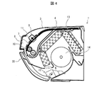
図7は、図4〜図6に示した風向変更装置の外観形状を示す斜視図であり、図8は、図7に対応した図であって、風向変更装置の一部を拡大して示す分解斜視図であり、図9は、図8に対応した図であって、風向変更装置の一部をさらに拡大して示す斜視図であり、図10は、図7に示した風向板の拡大側面図であり、図11は、図10に対応した図であって、風向板の平面図であり、図12は、図7に示した連動板の平面図である。
[Structure of wind direction changing device]
7 is a perspective view showing the external shape of the wind direction changing device shown in FIGS. 4 to 6, and FIG. 8 is a view corresponding to FIG. 7 and shows a part of the wind direction changing device in an enlarged manner. It is an exploded perspective view, FIG. 9 is a view corresponding to FIG. 8, and is a perspective view showing a part of the wind direction changing device in a further enlarged manner, and FIG. 10 is an enlarged view of the wind direction plate shown in FIG. It is a side view, FIG. 11 is a view corresponding to FIG. 10, is a plan view of a wind direction plate, and FIG. 12 is a plan view of an interlocking plate shown in FIG. 7.
これらの図を参照して説明すると、風向変更装置12は、基板33と、第1の風向板34,36と、複数の第2の風向板35,37と、第1の連動板44と、第2の連動板45と、第1の駆動アーム52と、第2の駆動アーム(図示せず)と、基板33の裏側の両端部に設けられた第1及び第2のモータ(駆動部)47、48とを備えている。
Explaining with reference to these figures, the wind
なお、本明細書において、第1の風向板は、基板の長手方向の両端側において基板に支持された風向板を意味し、第2の風向板は、第1の風向板以外のすべての風向板を意味するものとする。 In the present specification, the first wind direction plate means a wind direction plate supported by the substrate on both ends in the longitudinal direction of the substrate, and the second wind direction plate means all the wind directions other than the first wind direction plate. It shall mean a board.
また、本明細書において、第1の風向板および第2の風向板以外の各部材に対する「第1」および「第2」の文言は、風向変更装置を正面から見たときに、それぞれ風向変更装置の「右側」および「左側」を意味する。 Further, in the present specification, the words "first" and "second" for each member other than the first wind direction plate and the second wind direction plate change the wind direction when the wind direction changing device is viewed from the front. Means "right side" and "left side" of the device.
本実施形態では、図7に示すように、1枚の第1の風向板と、4枚の第2の風向板とから、後述する風向板群が形成されている。なお、本実施形態では、第1の風向板は、基板33の長手方向の両端側においてそれぞれが基板33に支持された第1の風向板34及び36を指しているが、これに限らず、第1の風向板は、基板33の長手方向の両端側のそれぞれにおいて基板33に支持された複数の風向板を含むものとしてもよい。
In the present embodiment, as shown in FIG. 7, a group of wind direction plates described later is formed from one first wind direction plate and four second wind direction plates. In the present embodiment, the first wind direction plate refers to the first
また、本実施形態では、第1の風向板34,36と、第2の風向板35,37とでは、それらが基板33に対して端側に配置されているかの点で異なる以外は、それらの基本的構造は共通している。しかし、説明の便宜上、本明細書ではこれら風向板には異なる符号を付すものとする。
Further, in the present embodiment, the first
本実施形態では、第1の風向板34,36及び複数の第2の風向板35,37の各々は、基板33の長手方向に、互いに間隔を置くようにして基板33に支持されており、それぞれが、空調された空気の吹き出し方向を制御する。
In the present embodiment, each of the first
第1の駆動アーム52は、図7に示すように風向変更装置12を正面側から見たときに、基板33の右側に設けられている。第1の駆動アーム52は、第1の減速装置(図示せず)を介して、基板33の右端側に設けられた第1のモータ47に接続されており、基板33の長手方向に沿って揺動可能に構成されている。
As shown in FIG. 7, the
一方、第2の駆動アーム(図示せず)は、図7に示すように風向変更装置12を正面側から見たときに、基板33の左側に設けられている。第2の駆動アームは、第2の減速装置(図示せず)を介して、基板33の左端側に設けられた第2のモータ48に接続されており、基板33の長手方向に沿って揺動可能に構成されている。
On the other hand, the second drive arm (not shown) is provided on the left side of the
なお、本明細書において「長手方向に沿って揺動」とは、基板33の長手方向に沿って直線状に往復する形態だけではなく、基板33の長手方向に沿って弧状に回動する形態も含んでいてよい。より具体的に説明すると、図7〜9に示す構成例では、第1の駆動アーム52が、基板33の長手方向に沿って弧状に回動する動き(弧状の円運動)は、後述する連動板44を介して、第1の風向板34及び複数の第2の風向板35に伝えられる。これにより、図11に示すように、例えば第1の風向板34の一方端は、第1の駆動アーム52の回動に連動して、基板33の長手方向に沿って弧状に回動する。この長手方向に沿った弧状の回動は、長手方向に沿った揺動の成分と、長手方向に直交する方向に沿った揺動の成分とを有している。ただし、長手方向に沿った揺動の幅は、長手方向に直交する方向に沿った揺動の幅より大きい。したがって、第1の駆動アーム52、連動板44及び第1の風向板34及び複数の第2の風向板35の主たる動きは、「長手方向に沿った揺動」と表現できる。「長手方向に沿った揺動」に関する以上の説明は、本願の全ての具体例にあてはまる。
In addition, in this specification, "swing along the longitudinal direction" is not only a form of linearly reciprocating along the longitudinal direction of the
第1の駆動アーム52及び第2の駆動アームそれぞれのアームの先端付近には、第1のピン55及び第2のピン(不図示)が設けられている。また、第1の連動板44及び第2の連動板45には、それぞれの一方端に、第1のピン55及び第2のピンに係合可能な第1の連結用開口部58及び第2の連結用開口部(図示せず)が設けられており、第1のピン55と第1の連結用開口部58、および第2のピンと第2の連結用開口部を互いに係合することによって、第1の駆動アーム52及び第2の駆動アームを揺動させて第1の連動板44及び第2の連動板45を、それぞれ基板33の長手方向に沿って揺動させることができる。
A
なお、本実施形態では、第1及び第2の風向板34〜37を、図7に示すように基板33の右半分に位置する右側風向板群65と、基板33の左側半分に位置する左側風向板群66とに区分し、各風向板群65,66をそれぞれ独立して制御可能な構成としている。なお、本実施形態では、右側風向板群65と、左側風向板群66とでは、基板33に対する配置が異なる以外はそれらの構成は共通する。そこで、以下では、右側風向板群65の構成を中心として説明する。
In the present embodiment, the first and second
まず、本実施形態に係る第1及び第2の風向板34,35ついて、再度図7〜11を参照して具体的に説明する。
First, the first and second
(風向板)
これらの図を参照して説明すると、第1の風向板34(以下、単に「風向板34」ともいう)は、主として、羽根部71(図9,10を参照)と、羽根部71を支持して基板33(図7等を参照)に立設された接続部81とを備えている。本実施形態では、接続部81が基板33に固定されることによって、第1の風向板34の一方端が基板33の長手方向に沿って揺動するように基板33に支持されている。羽根部71は、硬質部73と、硬質部73の一方側部に形成されて接続部81に接続される軟質部78とから構成されている。接続部81は、基板33からの立ち上がり方向が硬質部73と軟質部78との境界線に沿って平行または略平行になるように形成されている。また、軟質部78と接続部81との境界線が、軟質部78が前記長手方向に沿って弧状に回動(すなわち揺動)するための基軸となっている。これにより、第1の風向板34は、図11に示すように羽根部71が揺動可能となっている。
(Wind direction plate)
Explaining with reference to these figures, the first wind direction plate 34 (hereinafter, also simply referred to as “
硬質部73は、硬質部73の平面を貫通するようにして設けられた支軸用開口部74を備えている。支軸用開口部74において、基板33側の周壁には、当該周壁から支軸用開口部74の内方に向かって突出した第1の支軸(支持部)75が設けられている。なお、第1の支軸75の突出方向(軸方向)と、前記第1のピン55の突出方向(軸方向)とは平行であり、接続部81の立ち上がり方向とも平行である。第1の支軸75は、詳しくは後述する連動板44を回動可能に軸支するとともに、連動板44の平面に設けられた第1の開口部69(係止部)に、遊びを持って係止される。
The
第1の支軸75の軸方向両端側には、第1のフランジ部76及び第2のフランジ部77が設けられている。本実施形態では、第1のフランジ部76と第2のフランジ部77との間に連動板44(図7等を参照)を配置することによって、連動板44が第1の支軸75から抜けてしまうのを防止するとともに、連動板44と支軸用開口部74の周壁とが直接的に接触することを防止する。また、このように配置することによって、連動板44と駆動アーム52とが直接的に接触することを防止して、第1の風向板34及び第2の風向板35によるスムーズな風向変更を可能としている。
A
羽根部71における硬質部73及び軟質部78は、例えばポリプロピレン等の合成樹脂よって一体的に形成してもよい。その際、軟質部78が硬質部73よりも薄肉状になるようにしてもよい。このようにすれば、第1の風向板34及び複数の第2の風向板35の風向きを細かく制御することができる。
The
なお、本実施形態において、第2の風向板35は、基板33に対する配置が第1の風向板34と異なる他は、第1の風向板34と基本的には共通する。すなわち、本実施形態において、第2の風向板35は、第1の風向板34と同一形状を有するとともに、第2の風向板35には、第1の風向板34の第1の支軸75に対応する第2の支軸(支持部)86が設けられている点において共通する。一方で、第2の支軸86は、詳しくは次に説明する第1の連動板44の第2の開口部70に遊びを持って係止される点でのみ相違する。このようなことから、第2の風向板35の具体的な構成についての説明は省略する。
In the present embodiment, the second
(連動板)
続いて、第1の連動板44について説明する。第1の連動板44には、図12に示すように、第1の連動板44の平面を貫通するようにして設けられた第1の開口部(係止部)69と、複数の第2の開口部(係止部)70とが形成されている。
(Interlocking board)
Subsequently, the first interlocking
本実施形態では、第1の開口部69は、第2の開口部70よりも開口面積を大きくすることで、第1の連動板44が第1の風向板34を揺動させる際の遊びが、第1の連動板44が複数の第2の風向板35を揺動させる際の遊びよりも大きくなるように形成されている。なお、本実施形態では、図12に示すように、第1の開口部69の輪郭は、第1の連動板44の長手方向に対して長手側が斜めに設けられた略小判形状の一部分が、第1の連結用開口部58側に向かって略長鼻状に突出した形状である。一方、第2の開口部70の輪郭は、第1の連動板44に設けられた円形状が、第1の連動板44の長手方向両端側に向かって翼形状に延びた形状である。しかしながら、本発明における第1の開口部および第2の開口部の輪郭は、図12に示す形状に限定されるものではなく、例えば後述する変形例に示すような形状としてもよい。また、こうした遊びの大きさの相違による本発明の効果については後述する。
In the present embodiment, the
第1の開口部69及び複数の第2の開口部70は、それぞれが上述した第1の支軸75及び複数の第2の支軸86を、遊びを持たせて係止するように構成されている。
The
続いて、風向変更装置12の動作について、さらに図13を加えて具体的に説明する。
Subsequently, the operation of the wind
〔風向変更装置の動作〕
図13は、本実施形態に係る風向変更装置の動作を示す模式図であって、(a)は駆動アームが揺動していない状態における風向板の配置を示し、(b)は駆動アームが揺動したときの風向板の配置を示す。
[Operation of wind direction changing device]
13A and 13B are schematic views showing the operation of the wind direction changing device according to the present embodiment, in which FIG. 13A shows the arrangement of the wind direction plate when the drive arm is not swinging, and FIG. 13B shows the arrangement of the wind direction plate when the drive arm is not swinging. The arrangement of the wind direction plate when it swings is shown.
これらの図を参照して説明すると、第1の駆動アーム52が基板33の長手方向に沿って弧状に回動(揺動)すると、それに従って第1の駆動アーム52に連結された第1の連動板44も、基板33の長手方向に沿って弧状に回動(揺動)する。その際、第1の風向板34の第1の支軸75は、第2の風向板35における第2の支軸86が係止される第2の開口部70とは遊びの大きさの異なる第1の開口部69によって係止される。そのため、第1の風向板34と第2の風向板35との間には、第1の連動板44の揺動に伴った位置関係の違いが生じる。
Explaining with reference to these figures, when the
この違いによる結果について図13を参照してより詳細に説明すると、第1の駆動アーム52(図7等を参照)及び第2の駆動アーム(図示せず)が基板33の長手方向に沿って弧状に回動(揺動)していない状態において、第1の風向板34,36及び複数の第2の風向板35,37は、図13の(a)に示すように配置されている。これに対して、第1の駆動アーム52及び第2の駆動アームがそれぞれ基板33の長手方向に沿って弧状に回動(揺動)すると、図13の(b)に示すように、基板33の長手方向に対する第1の風向板34の傾き角度は、基板33の長手方向に対する第2の風向板35の傾き角よりも小さくなる。これは、第1の連動板44及び第2の連動板45の弧状の回動(揺動)に連動した第1の風向板34,36に対応する遊びが、第2の風向板35,37に対応する遊びよりも大きいためであり、第1の風向板34,36は、第2の風向板35,37と比較して、第1の連動板44及び第2の連動板45の各々の弧状の回動(揺動)と連動する影響を受けにくくなるからである。
The results of this difference will be described in more detail with reference to FIG. 13, where the first drive arm 52 (see FIG. 7 and the like) and the second drive arm (not shown) are along the longitudinal direction of the
その結果、第1の風向板34,36からの空気の吹き出し流の向きは、図13の(b)に示すように、第2の風向板35,37と比較して、第1の風向板34,36に傾きを与えないときの空気の吹き出し流の向き、すなわち図13の(a)に示す向き、に近くなる。
As a result, the direction of the air blowout flow from the first
これにより、図示しない空気調和機の吹出口の側面付近における空気の流れは安定するので、図20を参照して説明した渦の発生が抑制される。そのため、吹出口から正常に流れる状態と、風が逆流する状態との交互の発生、すなわちサージング現象を抑制することができる。また、これによれば風の逆流が抑制されるため、逆流した湿った風が冷たい風で冷やされ、吹出口の側壁面で結露が発生することが抑制される。 As a result, the flow of air near the side surface of the air outlet of the air conditioner (not shown) is stabilized, so that the generation of the vortex described with reference to FIG. 20 is suppressed. Therefore, it is possible to suppress the alternating occurrence of a state in which the wind normally flows from the outlet and a state in which the wind flows backward, that is, a surging phenomenon. Further, according to this, since the backflow of the wind is suppressed, the backflow of moist wind is cooled by the cold wind, and the occurrence of dew condensation on the side wall surface of the air outlet is suppressed.
なお、本実施形態では、上述したように空気調和機は、清掃装置等の特定の部品を備えているが、本発明の空気調和機は、少なくとも本発明に係る風向変更装置を備えていれば、他の部品を備えていなくてもよい。 In the present embodiment, as described above, the air conditioner is provided with specific parts such as a cleaning device, but the air conditioner of the present invention is provided with at least the wind direction changing device according to the present invention. , It does not have to be equipped with other parts.
また、本実施形態に係る風向変更装置は、特定形状の風向板及び連動板を備えているが、本発明に係る風向変更装置は、少なくとも基板の長手方向に、互いに間隔を置くようにして各々が基板に支持された複数の風向板と、複数の風向板の一方端の各々が、基板の長手方向に沿って揺動するように、複数の風向板を、各々遊びを持たせて係止する複数の係止部を備えた連動板と、連動板を基板の長手方向に沿って揺動させる駆動部とを有しており、基板の長手方向の少なくとも両端側において基板に支持された風向板の遊びの大きさは、他の風向板の遊びの大きさと異なる構成であれば、風向板及び連動板は他の構成を有していてもよい。 Further, the wind direction changing device according to the present embodiment includes a wind direction plate and an interlocking plate having a specific shape, but the wind direction changing devices according to the present invention are spaced apart from each other at least in the longitudinal direction of the substrate. The plurality of wind direction plates are locked with play so that the plurality of wind direction plates supported by the substrate and one end of each of the plurality of wind direction plates swing along the longitudinal direction of the substrate. It has an interlocking plate provided with a plurality of locking portions and a drive unit that swings the interlocking plate along the longitudinal direction of the substrate, and the wind direction supported by the substrate at least on both ends in the longitudinal direction of the substrate. The wind direction plate and the interlocking plate may have other configurations as long as the play size of the plate is different from the play size of the other wind direction plates.
さらに、本実施形態では、連動板が基板の長手方向に沿って弧状に回動する構成としているが、例えば、連動板が基板の長手方向に沿って直線状に往復するような構成としてもよい。 Further, in the present embodiment, the interlocking plate is configured to rotate in an arc shape along the longitudinal direction of the substrate, but for example, the interlocking plate may be configured to reciprocate linearly along the longitudinal direction of the substrate. ..
さらに、本実施形態に係る風向変更装置において、複数の風向板は右側及び左側風向板群に区別されているが、これらが一体化された構成としてもよい。 Further, in the wind direction changing device according to the present embodiment, the plurality of wind direction plates are classified into the right side and left side wind direction plate groups, but these may be integrated.
さらに、本実施形態では、特定形状の開口部を備えた連動板について説明したが、本発明において、連動板に設けられる開口部は他の形状を有していてもよい。 Further, in the present embodiment, the interlocking plate provided with the opening having a specific shape has been described, but in the present invention, the opening provided in the interlocking plate may have another shape.
そこで、以下では、連動板における開口部の形状の変形例について、図14を参照して説明する。なお、すでに説明した部材と同じ機能を有する部材については、同じ符号を付し、その説明を省略する。 Therefore, in the following, a modified example of the shape of the opening in the interlocking plate will be described with reference to FIG. Members having the same functions as the members already described will be designated by the same reference numerals, and the description thereof will be omitted.
〔開口部の変形例〕
図14の(a)〜(c)は、それぞれ、本実施形態に係る連動板の変形例を示す平面図である。
[Modification example of opening]
14 (a) to 14 (c) are plan views showing a modified example of the interlocking plate according to the present embodiment, respectively.
はじめに、図14の(a)に示すように、連動板54には、連動板54の長手方向に対する第1の開口部72の傾き角度が異なる点で図12に示した第1の開口部69とは異なる、第1の開口部72が設けられていてもよい。なお、第1の連結用開口部58は、図12にも示すように、長手方向に直交する方向に長い長孔として形成されている。そして、第1の開口部72が、第1の開口部69と同様に、長手方向に対して傾き角度を有しているのは、第1の連結用開口部58に案内される第1のピン55(図7〜9を参照)の動き方向が、長手方向に対する交差成分を持っているためである。
First, as shown in FIG. 14A, the interlocking
または、図14の(b)に示すように、連動板64には、第1の開口部94の大きさが異なる点で図12に示した第1の開口部69とは異なる、第1の開口部94が設けられていてもよい。なお、図14の(b)に示す第1の開口部94は、図12に示した第1の開口部69よりも開口部の大きさが小さくなるように設けられている。
Alternatively, as shown in FIG. 14 (b), the interlocking
あるいはまた、図14の(c)に示すように、連動板84は、連動板84の長手方向に対する傾き角度が異なるとともに、互いに形状の異なる複数の第1の開口部77,96を有する点で、図12に示した連動板44と異なるような構成であってもよい。
Alternatively, as shown in FIG. 14 (c), the interlocking
図14の(a)及び(b)に示すように、第1の開口部72,94を変更することによって、第1の風向板34の、基板の長手方向に対する風向角を容易に異ならせることができる。
As shown in FIGS. 14A and 14B, the wind direction angle of the first
また、図14の(c)に示すようにして、複数の第1の風向板34の各々を、互いに大きさの異なる2種以上の遊びでもって係止されるような構成とすれば、複数の第1の風向板34について、基板33(図7等を参照)の長手方向に対する風向板の角度を異ならせることができる。したがって、この構成によれば、空調された空気の吹き出し方向を、基板33の長手方向の位置に応じて、より多様に異ならせることができる。
Further, as shown in FIG. 14 (c), if each of the plurality of first
さらに、図14に示したような構成の他にも、例えば、第1の開口部および第2の開口部をそれぞれ円形状とするとともに、第1の開口部の円形状を第2の開口部の円形状よりも大きくしてもよい。なお、このような場合には、第1の開口部から第1の支軸が抜け出ないように、第1の支軸に第1の開口部を指し込んだ後に、第1の支軸に対して別体の抜け防止部材(図示せず)を取り付けることが好ましい。 Further, in addition to the configuration as shown in FIG. 14, for example, the first opening and the second opening have a circular shape, and the circular shape of the first opening has a circular shape of the second opening. It may be larger than the circular shape of. In such a case, after pointing the first opening into the first support shaft so that the first support shaft does not come out from the first opening, the first support shaft is used. It is preferable to attach a separate pull-out prevention member (not shown).
〔実施形態2〕
本発明に係る風向変更装置の他の実施形態について、図15〜図17を参照して説明する。
[Embodiment 2]
Other embodiments of the wind direction changing device according to the present invention will be described with reference to FIGS. 15 to 17.
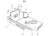
図15は、本実施形態に係る風向変更装置の一部分を拡大して示す斜視図である。また、図16は、図15に対応した図であって、(a)は主連動板の正面図であり、(b)は主連動板の平面図であり、(c)は副連動板の正面図であり、(d)は副連動板の平面図であり、(e)は主連動板の斜視図であり、(f)は副連動板の斜視図である。また、図17は、図15に対応した図であって、風向変更装置を正面から見たときの各構成部材の動きを説明するための、風向変更装置の一部を模式的に示す正面図である。なお、実施形態1において説明した部材と同じ機能を有する部材については、同じ符号を付し、その説明を省略する。 FIG. 15 is an enlarged perspective view showing a part of the wind direction changing device according to the present embodiment. 16A and 16B are views corresponding to FIG. 15, where FIG. 16A is a front view of the main interlocking plate, FIG. 16B is a plan view of the main interlocking plate, and FIG. It is a front view, (d) is a plan view of an auxiliary interlocking plate, (e) is a perspective view of a main interlocking plate, and (f) is a perspective view of an auxiliary interlocking plate. Further, FIG. 17 is a view corresponding to FIG. 15, and is a front view schematically showing a part of the wind direction changing device for explaining the movement of each component when the wind direction changing device is viewed from the front. Is. The members having the same functions as the members described in the first embodiment are designated by the same reference numerals, and the description thereof will be omitted.
これらの図を参照して説明すると、本実施形態に係る風向変更装置15において、連動板80は、主連動板82と、副連動板85とから構成されている。主連動板82は、基板33の長手方向端部側において、その一部が上方に突出して形成された突出部87を有するとともに、突出部87には、副連動板85と当接可能な内壁88が形成されている。一方、副連動板85は、正面視略U字形状に構成され、主連動板82に対してスライド可能に係合している。また、副連動板85は、突出部87の内壁88に当接する当接部95を有している。
Explaining with reference to these figures, in the wind
主連動板82は、基板33の長手方向の両端側において基板33に支持された第1の風向板(風向板)34以外の風向板である、複数の第2の風向板35を、遊びを持たせて係止するために、複数の主開口部(主係止部)89を備えている。一方、副連動板85は、基板33の長手方向の少なくとも端側において基板33に支持された第1の風向板(風向板)34を、各々遊びを持たせて係止する副開口部92(副係止部)を備えている。
The
主連動板82は、モータ(図示せず)によって、基板33の長手方向に沿って揺動されるように構成されている。また、主連動板82の突出部87の内壁88が副連動板85の当接部95に当接すると、副連動板85は揺動されるように構成されている。
The
このような構成の風向変更装置15における遊びについて図17に基づいて説明すると、本実施形態における遊びは、図示しないモータの力(駆動力)を与えられて、主連動板82が動いたときに、第2の風向板35に対応する主連動板82の1つの作用点(主開口部89の周壁に相当)が、第2の風向板35に当接するまでに移動する距離(L1)に相当する。すなわち、この遊びは、主連動板82にモータの力が与えられて主連動板82が揺動したときに、主連動板82が第2の風向板35に当接するまでに移動する距離に相当する。
The play in the wind
第2の風向板35に当接した作用点は、移動を継続することによって、第2の風向板35の向きを、作用点が移動する方向に沿って変える。したがってこの距離を短くすれば、この作用点は、対応する第2の風向板35に早く当接し、この距離を長くすれば、作用点は、対応する第2の風向板35に遅れて当接する。
The point of action in contact with the second
つまり、各作用点の動きは、主連動板82の動きに一致するので、各作用点が移動を開始してから止まるまでの総移動距離は同じになる。そうすると、第2の風向板35に早く当接する作用点は、第2の風向板35に遅く当接する作用点よりも、第2の風向板35の向きを大きく変えることができる。
That is, since the movement of each action point coincides with the movement of the main interlocking
したがって、図17に示す風向変更装置15において、主連動板82が第2の風向板35に当接するまでに主連動板82が移動する距離、および、副連動板85が第1の風向板34に当接するために副連動板85が移動する距離をそれぞれ(L1)とし、主連動板82(の内壁88)が副連動板85(の当接部95)に当接するまでに主連動板82が移動する距離を(L2)とすると、副連動板85は、主連動板82の揺動によって距離(L2)まで揺動させられた後、主連動板82が副連動板85に当接して初めて、副連動板85は、第1の風向板34を距離(L1)だけ揺動させることができる。
Therefore, in the wind
このような構成によれば、第1の風向板34は、第2の風向板35よりも遅れて距離(L1)までの揺動を開始する。その際、第2の風向板35の遊びは、距離(L1)に対応し、一方で、第1の風向板34の遊びは、距離(L1+L2)に対応する。このような構成によっても、第1の風向板34の遊びを第2の風向板35の遊びより大きくすることができる。
According to such a configuration, the first
〔実施形態3〕
本発明に係る風向変更装置のさらに他の実施形態について、図18および図19を参照して説明する。
[Embodiment 3]
Yet another embodiment of the wind direction changing device according to the present invention will be described with reference to FIGS. 18 and 19.
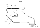
図18は、本実施形態に係る風向板の側面図であり、図19は、図18に示した風向板の上面図である。なお、本実施形態において、実施形態1及び2において説明した部材と同じ機能を有する部材については同じ符号を参照し、その説明を省略する。 FIG. 18 is a side view of the wind direction plate according to the present embodiment, and FIG. 19 is a top view of the wind direction plate shown in FIG. In the present embodiment, the same reference numerals are referred to for the members having the same functions as the members described in the first and second embodiments, and the description thereof will be omitted.
これらの図を参照して説明すると、本実施形態において、風向板134は、主として羽根部173から構成されている。羽根部173は、羽根部173の平面を貫通するようにして設けられた支持用開口部174を備えている。支持用開口部174において、図示しない基板側の周壁には、当該周壁から支持用開口部174の内方に向かって突出した第1の支軸(支持部)175が設けられている。また、基板側に配置される羽根部173の末端には、ツメ部178が接続されている。さらに、基板の上面には、基板の上面で回動可能な回転盤136が取付けられている。回転盤136には、ツメ部178を取り付け可能な取付部(図示せず)が設けられている。本実施形態では、ツメ部178を取付部に取付けることで、風向板134の一方端は基板の長手方向に沿って揺動し、他方端は回動するようにして基板に支持される。そのため、ツメ部178を回転盤136に取付けるとともに、第1の支軸175によって連動板(図示せず)を回動可能に軸支すれば、連動板の揺動に伴った風向板134の揺動を実現することができる。
Explaining with reference to these figures, in the present embodiment, the
本実施形態によれば、風向板の羽根部を、実施形態1に示したように硬質部と軟質部の2つの異なる部材から構成するのではなく、1つの部材から構成することができるため、実施形態1に示した風向板34(図10を参照)と比較して、風向板134の構成を簡略化することができる。
According to the present embodiment, the blade portion of the wind direction plate can be composed of one member instead of the two different members of the hard portion and the soft portion as shown in the first embodiment. The configuration of the
〔まとめ〕
本発明の態様1に係る風向変更装置(12)は、複数の風向板(第1及び第2の風向板34〜37)の各々が、当該複数の風向板の一方端の各々が基板(33)の長手方向に沿って揺動するように、基板(33)の長手方向において互いに間隔を置くようにして基板(33)に支持され、空調された空気の吹き出し方向を制御する複数の風向板(第1及び第2の風向板34〜37)と、当該複数の風向板の一方端の各々が、当該長手方向に沿って揺動するように、当該複数の風向板を、各々遊びを持たせて係止する複数の開口部(第1及び第2の開口部69,70、係止部に相当)を備えた連動板(第1及び第2の連動板44,45)と、当該連動板を前記長手方向に沿って揺動させるモータ47,48(駆動部)とを有しており、前記長手方向の少なくとも両端側において基板(33)に支持された風向板(第1の風向板34,36)の当該遊びの大きさは、他の風向板(第2の風向板35,37)の遊びの大きさと異なっている。
[Summary]
In the wind direction changing device (12) according to the first aspect of the present invention, each of the plurality of wind direction plates (first and second
上記構成によれば、基板の長手方向の少なくとも両端側において基板に支持された風向板は、他の風向板の遊びとは異なる遊びで係止される。そのため、連動板の揺動に伴った風向板と連動板との位置関係の違いが生じる。これにより、風向板による風向の違いが生じる。 According to the above configuration, the wind direction plate supported by the substrate at least on both ends in the longitudinal direction of the substrate is locked with a play different from the play of other wind direction plates. Therefore, there is a difference in the positional relationship between the wind direction plate and the interlocking plate due to the swing of the interlocking plate. This causes a difference in the wind direction depending on the wind direction plate.
本発明の態様2に係る風向変更装置は、上記態様1において、前記長手方向の少なくとも両端側において基板に支持された風向板の前記遊びの大きさは、前記他の風向板の前記遊びの大きさよりも大きくてもよい。 In the wind direction changing device according to the second aspect of the present invention, in the first aspect, the play size of the wind direction plate supported by the substrate at least on both ends in the longitudinal direction is the play size of the other wind direction plates. It may be larger than that.
上記構成によれば、連動板の揺動と連動した基板の長手方向に対する風向板の傾き角度に関して、当該長手方向の少なくとも両端側において基板に支持された風向板(以下、両端側風向板という)の傾き角度は、他の風向板の角度よりも小さくなる。これは、両端側風向板の係止部における遊びが、他の風向板の係止部における遊びよりも大きいため、両端側風向板は、他の風向板と比較して、連動板の揺動と連動する影響を受けにくくなるためである。これにより、両端側風向板からの空気の吹き出し流の向きは、他の風向板と比較して、両端側風向板に傾きを与えないときの空気の吹き出し流の向きに近くなる。 According to the above configuration, with respect to the inclination angle of the wind direction plate with respect to the longitudinal direction of the substrate interlocked with the swing of the interlocking plate, the wind direction plate supported by the substrate at least on both ends in the longitudinal direction (hereinafter referred to as both end side wind direction plates). The tilt angle of is smaller than the angle of other wind direction plates. This is because the play in the locking portion of the wind direction plate on both ends is larger than the play in the locking portion of the other wind direction plates, so that the wind direction plate on both ends swings the interlocking plate as compared with the other wind direction plates. This is because it is less likely to be affected by interlocking with. As a result, the direction of the air blow-out flow from the wind direction plates on both ends is closer to the direction of the air blow-out when the wind direction plates on both ends are not tilted, as compared with other wind direction plates.
本発明の態様3に係る風向変更装置は、上記態様1において、前記係止部は、前記連動板の平面を貫通するようにして設けられた開口部であり、前記風向板は、前記連動板を回動可能に軸支するとともに、当該連動板の当該開口部に係止される支持部を備えていてもよい。 In the wind direction changing device according to the third aspect of the present invention, in the first aspect, the locking portion is an opening provided so as to penetrate the plane of the interlocking plate, and the wind direction plate is the interlocking plate. May be provided with a support portion that rotatably supports the shaft and is locked to the opening of the interlocking plate.
上記構成によれば、簡易な構成によって、風向板による風向きの違いの発生を実現することができる。 According to the above configuration, it is possible to realize the generation of a difference in the wind direction due to the wind direction plate by a simple configuration.
本発明の態様4に係る風向変更装置は、上記態様1〜3において、前記遊びは、駆動力を与えられて働く前記連動板の作用点が、前記風向板の1つに当接して当該風向板の1つを動かし始めるまでに移動する距離であって、前記長手方向の少なくとも両端側において基板に支持された風向板に対応する当該距離は、前記他の風向板に対応する当該距離よりも大きくてもよい。 In the wind direction changing device according to the fourth aspect of the present invention, in the first to third aspects, the play point of the interlocking plate that works by being given a driving force abuts on one of the wind direction plates. The distance to move one of the plates before starting to move, and the distance corresponding to the wind direction plate supported by the substrate at least on both ends in the longitudinal direction is larger than the distance corresponding to the other wind direction plates. It may be large.
上記構成によれば、遊びは、連動板に駆動力が与えられて、連動板が動いたときに、風向板の1つに対応する連動板の1つの作用点が、当該風向板の1つに当接するまでに移動する距離に相当する。当該風向板の1つに当接した作用点は、移動を継続することによって、当該風向板の1つの向きを、作用点が移動する方向に沿って変える。上記距離を短くすれば、作用点は、対応する風向板に早く当接し、上記距離を長くすれば、作用点は、対応する風向板に遅れて当接する。各作用点の動きは、連動板の動きに一致するので、各作用点が移動を開始してから止まるまでの総移動距離は同じになる。そうすると、風向板に早く当接する作用点は、風向板に遅く当接する作用点よりも、風向板の向きを大きく変えることができる。こうして、簡易な構成によって、風向板による風向の違いの発生を実現することができる。 According to the above configuration, in the play, when a driving force is applied to the interlocking plate and the interlocking plate moves, one point of action of the interlocking plate corresponding to one of the wind direction plates is one of the wind direction plates. Corresponds to the distance traveled before contacting. The point of action in contact with one of the wind direction plates changes the direction of one of the wind direction plates along the direction in which the point of action moves by continuing the movement. If the distance is shortened, the point of action abuts quickly on the corresponding wind direction plate, and if the distance is lengthened, the point of action abuts later on the corresponding wind direction plate. Since the movement of each action point matches the movement of the interlocking plate, the total movement distance from when each action point starts moving to when it stops is the same. Then, the point of action that comes into contact with the wind direction plate earlier can change the direction of the wind direction plate more than the point of action that comes into contact with the wind direction plate later. In this way, with a simple configuration, it is possible to realize the generation of a difference in the wind direction due to the wind direction plate.
本発明の態様5に係る風向変更装置は、上記態様1〜4において、前記長手方向の両端側のそれぞれにおいて基板に支持された複数の風向板は、互いに大きさの異なる2種以上の遊びを有していてもよい。 In the wind direction changing device according to the fifth aspect of the present invention, in the first to fourth aspects, the plurality of wind direction plates supported on the substrate on each of both ends in the longitudinal direction play two or more types of play having different sizes. You may have.
上記構成によれば、長手方向の両端側のそれぞれにおいて基板に支持された複数の風向板について、長手方向に対する風向板の角度を異ならせることができる。したがって、空調された空気の吹き出し方向を、長手方向の位置に応じて、より多様に異ならせることができる。 According to the above configuration, the angles of the wind direction plates with respect to the longitudinal direction can be made different for the plurality of wind direction plates supported on the substrate on both ends in the longitudinal direction. Therefore, the blowing direction of the conditioned air can be made different depending on the position in the longitudinal direction.
本発明の態様6に係る風向変更装置は、上記態様1において、前記連動板は、主連動板と、当該主連動板に対してスライド可能に係合するとともに当該主連動板に当接する当接部を有する副連動板とから構成され、前記主連動板は、前記長手方向の前記両端側において基板に支持された前記風向板以外の他の複数の風向板を、各々遊びを持たせて係止する複数の主係止部を備えており、前記副連動板は、前記長手方向の少なくとも両端側において基板に支持された前記風向板を、各々遊びを持たせて係止する副係止部を備えており、前記主連動板は、前記駆動部によって、前記長手方向に沿って揺動され、前記副連動板に当接して、当該副連動板を揺動させるように構成されていてもよい。 In the wind direction changing device according to the sixth aspect of the present invention, in the first aspect, the interlocking plate is slidably engaged with the main interlocking plate and abutted against the main interlocking plate. The main interlocking plate is composed of a sub interlocking plate having a portion, and the main interlocking plate engages a plurality of wind direction plates other than the wind direction plate supported by the substrate on both end sides in the longitudinal direction with play. The sub-interlocking plate is provided with a plurality of main locking portions for stopping, and the sub-interlocking plate is a sub-locking portion that locks the wind direction plates supported by the substrate at least on both ends in the longitudinal direction with play. The main interlocking plate is configured to swing along the longitudinal direction by the driving unit and abut on the sub interlocking plate to swing the sub interlocking plate. Good.
上記構成によれば、副連動板に係止された両端側風向板は、主連動板に係止された、両端側風向板以外の風向板よりも遅れて揺動を開始する。なぜなら、主連動板の揺動によって揺動させられた後、主連動板が副連動板に当接して初めて、副連動板は両端側風向板を揺動させることができるからである。これにより、両端側風向板の遊びを、両端側風向板以外の風向板の遊びより大きくすることができる。 According to the above configuration, the wind direction plates on both ends locked to the sub interlocking plate start swinging later than the wind direction plates other than the wind direction plates on both ends locked to the main interlocking plate. This is because the sub-interlocking plate can swing the wind direction plates on both ends only after the main interlocking plate comes into contact with the sub-interlocking plate after being swung by the swing of the main interlocking plate. As a result, the play of the wind direction plates on both ends can be made larger than the play of the wind direction plates other than the wind direction plates on both ends.
本発明に係る空気調和機は、上記いずれかの態様に係る風向変更装置を備えたものである。 The air conditioner according to the present invention is provided with the wind direction changing device according to any one of the above aspects.
上記構成によれば、容易な構成によって風向を変更可能である。そのため、安価な構造によって製造コストを低減することができる。 According to the above configuration, the wind direction can be changed by a simple configuration. Therefore, the manufacturing cost can be reduced by the inexpensive structure.
本発明は上述した各実施形態に限定されるものではなく、請求項に示した範囲で種々の変更が可能であり、異なる実施形態にそれぞれ開示された技術的手段を適宜組み合わせて得られる実施形態についても本発明の技術的範囲に含まれる。さらに、各実施形態にそれぞれ開示された技術的手段を組み合わせることにより、新しい技術的特徴を形成することができる。 The present invention is not limited to the above-described embodiments, and various modifications can be made within the scope of the claims, and the embodiments obtained by appropriately combining the technical means disclosed in the different embodiments. Is also included in the technical scope of the present invention. Furthermore, new technical features can be formed by combining the technical means disclosed in each embodiment.
1 ・・・空気調和機
12,15・・・風向変更装置
33 ・・・基板
34,36・・・第1の風向板(両端側において基板に支持された風向板)
35 ・・・第2の風向板(風向板)
44 ・・・第1の連動板(連動板)
45 ・・・第2の連動板(連動板)
47,48・・・モータ(駆動部)
69 ・・・第1の開口部(係止部)
70 ・・・第2の開口部(係止部)
80 ・・・連動板
82 ・・・主連動板
85 ・・・副連動板
1 ...
35 ・ ・ ・ Second wind direction plate (wind direction plate)
44 ・ ・ ・ First interlocking plate (interlocking plate)
45 ・ ・ ・ Second interlocking plate (interlocking plate)
47, 48 ... Motor (drive unit)
69 ・ ・ ・ First opening (locking part)
70 ... Second opening (locking portion)
80 ・ ・ ・
Claims (6)
前記複数の風向板の一方端の各々が、前記長手方向に沿って揺動するように、前記複数の風向板を、各々遊びを持たせて係止する複数の係止部を備えた連動板と、
前記連動板を前記長手方向に沿って揺動させる駆動部とを有しており、
前記風向板の前記一方端と反対側の空気の導入側の端部が前記基板に固定され、
前記長手方向の少なくとも両端側において前記一方端と反対側の端部が当該基板に固定された風向板の前記遊びの大きさは、前記他の風向板の前記遊びの大きさよりも大きく、
前記遊びは、駆動力を与えられて働く前記連動板の作用点が、前記風向板の1つに当接して当該風向板の1つを動かし始めるまでに移動する距離であって、前記長手方向の少なくとも両端側において基板に支持された風向板に対応する当該距離は、前記他の風向板に対応する当該距離よりも大きいことを特徴とする風向変更装置。 Each of the plurality of wind direction plates is spaced apart from each other in the longitudinal direction of the substrate so that each end of the air blowing side of the plurality of wind direction plates swings along the longitudinal direction of the substrate. A plurality of wind direction plates supported by the substrate and controlling the blowing direction of air-conditioned air,
An interlocking plate provided with a plurality of locking portions for locking the plurality of wind direction plates with play so that each one end of the plurality of wind direction plates swings along the longitudinal direction. When,
It has a drive unit that swings the interlocking plate along the longitudinal direction.
The end on the air introduction side opposite to the one end of the wind direction plate is fixed to the substrate.
It said longitudinal end portion of the one end and the opposite side at least both ends of the play of the wind direction plate fixed on the substrate size is much larger than the size of the play of the other wind direction plate,
The play is a distance that the action point of the interlocking plate that works by being given a driving force moves until it comes into contact with one of the wind direction plates and starts moving one of the wind direction plates, and is the longitudinal direction. A wind direction changing device, characterized in that the distance corresponding to the wind direction plate supported by the substrate on at least both ends of the wind direction plate is larger than the distance corresponding to the other wind direction plates .
前記主連動板は、前記長手方向の前記両端側において前記基板に支持された前記風向板以外の他の複数の風向板を、各々遊びを持たせて係止する複数の主係止部を備えており、
前記副連動板は、前記長手方向の少なくとも両端側において前記基板に支持された前記風向板を、各々遊びを持たせて係止する副係止部を備えており、
前記主連動板は、前記駆動部によって、前記長手方向に沿って揺動され、前記副連動板に当接して、当該副連動板を揺動させるように構成されていることを特徴とする請求項1に記載の風向変更装置。 The interlocking plate is composed of a main interlocking plate and a sub interlocking plate having a contact portion that slidably engages with the main interlocking plate and abuts on the main interlocking plate.
The main interlocking plate includes a plurality of main locking portions that lock a plurality of wind direction plates other than the wind direction plates supported on the substrate on both end sides in the longitudinal direction with play. And
The sub-interlocking plate includes sub-locking portions that lock the wind direction plates supported by the substrate at least on both ends in the longitudinal direction with play.
The claim is characterized in that the main interlocking plate is swung along the longitudinal direction by the driving unit, abuts on the sub interlocking plate, and the sub interlocking plate is swung. Item 1. The wind direction changing device according to item 1.
前記複数の風向板の一方端の各々が、前記長手方向に沿って揺動するように、前記複数の風向板を、各々遊びを持たせて係止する複数の係止部を備えた連動板と、
前記連動板を前記長手方向に沿って揺動させる駆動部とを有しており、
前記風向板の前記一方端と反対側の空気の導入側の端部が前記基板に固定され、
前記長手方向の少なくとも両端側において前記一方端と反対側の端部が当該基板に固定された風向板の前記遊びの大きさは、前記他の風向板の前記遊びの大きさよりも大きく、
前記連動板は、主連動板と、当該主連動板に対してスライド可能に係合するとともに当該主連動板に当接する当接部を有する副連動板とから構成され、
前記主連動板は、前記長手方向の前記両端側において前記基板に支持された前記風向板以外の他の複数の風向板を、各々遊びを持たせて係止する複数の主係止部を備えており、
前記副連動板は、前記長手方向の少なくとも両端側において前記基板に支持された前記風向板を、各々遊びを持たせて係止する副係止部を備えており、
前記主連動板は、前記駆動部によって、前記長手方向に沿って揺動され、前記副連動板に当接して、当該副連動板を揺動させるように構成されていることを特徴とする風向変更装置。 Each of the plurality of wind direction plates is spaced apart from each other in the longitudinal direction of the substrate so that each end of the air blowing side of the plurality of wind direction plates swings along the longitudinal direction of the substrate. A plurality of wind direction plates supported by the substrate and controlling the blowing direction of air-conditioned air,
An interlocking plate provided with a plurality of locking portions for locking the plurality of wind direction plates with play so that each one end of the plurality of wind direction plates swings along the longitudinal direction. When,
It has a drive unit that swings the interlocking plate along the longitudinal direction.
The end on the air introduction side opposite to the one end of the wind direction plate is fixed to the substrate.
The play size of the wind direction plate whose ends opposite to one end are fixed to the substrate at least on both ends in the longitudinal direction is larger than the play size of the other wind direction plates.
The interlocking plate is composed of a main interlocking plate and a sub interlocking plate having a contact portion that slidably engages with the main interlocking plate and abuts on the main interlocking plate.
The main interlocking plate includes a plurality of main locking portions that lock a plurality of wind direction plates other than the wind direction plates supported on the substrate on both end sides in the longitudinal direction with play. And
The sub-interlocking plate includes sub-locking portions that lock the wind direction plates supported by the substrate at least on both ends in the longitudinal direction with play.
The wind direction is characterized in that the main interlocking plate is swung along the longitudinal direction by the driving unit, comes into contact with the sub interlocking plate, and swings the sub interlocking plate. Change device.
Priority Applications (1)
| Application Number | Priority Date | Filing Date | Title |
|---|---|---|---|
| JP2016166313A JP6826842B2 (en) | 2016-08-26 | 2016-08-26 | Wind direction changing device and air conditioner equipped with this |
Applications Claiming Priority (1)
| Application Number | Priority Date | Filing Date | Title |
|---|---|---|---|
| JP2016166313A JP6826842B2 (en) | 2016-08-26 | 2016-08-26 | Wind direction changing device and air conditioner equipped with this |
Publications (2)
| Publication Number | Publication Date |
|---|---|
| JP2018031575A JP2018031575A (en) | 2018-03-01 |
| JP6826842B2 true JP6826842B2 (en) | 2021-02-10 |
Family
ID=61303311
Family Applications (1)
| Application Number | Title | Priority Date | Filing Date |
|---|---|---|---|
| JP2016166313A Active JP6826842B2 (en) | 2016-08-26 | 2016-08-26 | Wind direction changing device and air conditioner equipped with this |
Country Status (1)
| Country | Link |
|---|---|
| JP (1) | JP6826842B2 (en) |
Families Citing this family (1)
| Publication number | Priority date | Publication date | Assignee | Title |
|---|---|---|---|---|
| KR102457780B1 (en) * | 2017-10-13 | 2022-10-24 | 엘지전자 주식회사 | Air conditioner |
Family Cites Families (7)
| Publication number | Priority date | Publication date | Assignee | Title |
|---|---|---|---|---|
| US4653384A (en) * | 1985-12-31 | 1987-03-31 | Kabushiki Kaisha Toshiba | Air supply adjusting mechanism for air conditioner |
| JPH0777343A (en) * | 1993-09-07 | 1995-03-20 | Daikin Ind Ltd | Air conditioner |
| JP3713112B2 (en) * | 1996-10-28 | 2005-11-02 | 松下電器産業株式会社 | Louver mechanism |
| JP2000227247A (en) * | 1999-02-05 | 2000-08-15 | Fujitsu General Ltd | Wind direction-adjusting device of air-conditioner |
| CN1840976A (en) * | 2005-03-31 | 2006-10-04 | 日立家用电器公司 | Air conditioner |
| JP5069988B2 (en) * | 2007-09-19 | 2012-11-07 | シャープ株式会社 | Wind direction changing device and air conditioner having the same |
| JP6066783B2 (en) * | 2013-03-07 | 2017-01-25 | 三菱電機株式会社 | Air conditioner indoor unit and air conditioner equipped with the same |
-
2016
- 2016-08-26 JP JP2016166313A patent/JP6826842B2/en active Active
Also Published As
| Publication number | Publication date |
|---|---|
| JP2018031575A (en) | 2018-03-01 |
Similar Documents
| Publication | Publication Date | Title |
|---|---|---|
| JP4913696B2 (en) | Wind direction changing device and air conditioner having the same | |
| KR101609082B1 (en) | Indoor unit of air conditioner | |
| JP5069988B2 (en) | Wind direction changing device and air conditioner having the same | |
| JP2007292328A (en) | Air conditioner | |
| WO2013031306A1 (en) | Air-conditioning indoor unit | |
| WO2015192524A1 (en) | Air opening component | |
| JP6826842B2 (en) | Wind direction changing device and air conditioner equipped with this | |
| JP2009299991A (en) | Wind direction changing device and air conditioning device comprising the same | |
| JP5375900B2 (en) | Air conditioning indoor unit | |
| WO2015080165A1 (en) | Indoor unit | |
| JP2000283544A (en) | Ceiling embedded air conditioner | |
| JP5306032B2 (en) | Air conditioner indoor unit | |
| JP5817815B2 (en) | Indoor unit | |
| JP2006064216A (en) | Floor mounted air conditioner | |
| JP2008025880A (en) | Air conditioner | |
| KR20050049308A (en) | Air conditioner | |
| WO2008038582A1 (en) | Air conditioner | |
| JP6418865B2 (en) | Air conditioner | |
| JP6081346B2 (en) | Indoor unit | |
| CN112682850A (en) | Air conditioner | |
| JP2006300460A (en) | Air conditioner | |
| JP2007132608A (en) | Air conditioner | |
| JP2010043805A (en) | Floor-installed air conditioner | |
| JP6221061B2 (en) | Air conditioner | |
| JPS60243441A (en) | Air flow cut-off mechanism for ventilator |
Legal Events
| Date | Code | Title | Description |
|---|---|---|---|
| A621 | Written request for application examination |
Free format text: JAPANESE INTERMEDIATE CODE: A621 Effective date: 20190320 |
|
| A977 | Report on retrieval |
Free format text: JAPANESE INTERMEDIATE CODE: A971007 Effective date: 20200124 |
|
| A131 | Notification of reasons for refusal |
Free format text: JAPANESE INTERMEDIATE CODE: A131 Effective date: 20200204 |
|
| A521 | Written amendment |
Free format text: JAPANESE INTERMEDIATE CODE: A523 Effective date: 20200406 |
|
| A131 | Notification of reasons for refusal |
Free format text: JAPANESE INTERMEDIATE CODE: A131 Effective date: 20200804 |
|
| A521 | Written amendment |
Free format text: JAPANESE INTERMEDIATE CODE: A523 Effective date: 20200929 |
|
| TRDD | Decision of grant or rejection written | ||
| A01 | Written decision to grant a patent or to grant a registration (utility model) |
Free format text: JAPANESE INTERMEDIATE CODE: A01 Effective date: 20210106 |
|
| A61 | First payment of annual fees (during grant procedure) |
Free format text: JAPANESE INTERMEDIATE CODE: A61 Effective date: 20210118 |
|
| R150 | Certificate of patent or registration of utility model |
Ref document number: 6826842 Country of ref document: JP Free format text: JAPANESE INTERMEDIATE CODE: R150 |