JP6822988B2 - Optical node device - Google Patents
Optical node device Download PDFInfo
- Publication number
- JP6822988B2 JP6822988B2 JP2018021429A JP2018021429A JP6822988B2 JP 6822988 B2 JP6822988 B2 JP 6822988B2 JP 2018021429 A JP2018021429 A JP 2018021429A JP 2018021429 A JP2018021429 A JP 2018021429A JP 6822988 B2 JP6822988 B2 JP 6822988B2
- Authority
- JP
- Japan
- Prior art keywords
- optical
- core
- light
- output
- input
- Prior art date
- Legal status (The legal status is an assumption and is not a legal conclusion. Google has not performed a legal analysis and makes no representation as to the accuracy of the status listed.)
- Active
Links
- 230000003287 optical effect Effects 0.000 title claims description 251
- 239000000835 fiber Substances 0.000 claims description 108
- 230000003321 amplification Effects 0.000 claims description 29
- 238000003199 nucleic acid amplification method Methods 0.000 claims description 29
- 230000005540 biological transmission Effects 0.000 claims description 24
- 230000002238 attenuated effect Effects 0.000 claims description 7
- 238000000926 separation method Methods 0.000 claims description 4
- 230000005284 excitation Effects 0.000 description 33
- 238000012937 correction Methods 0.000 description 10
- 238000010586 diagram Methods 0.000 description 10
- 238000001514 detection method Methods 0.000 description 7
- 239000013307 optical fiber Substances 0.000 description 6
- 238000001228 spectrum Methods 0.000 description 5
- 230000007423 decrease Effects 0.000 description 4
- 239000004065 semiconductor Substances 0.000 description 3
- 238000004891 communication Methods 0.000 description 2
- 150000002500 ions Chemical class 0.000 description 2
- 239000000463 material Substances 0.000 description 2
- 238000005253 cladding Methods 0.000 description 1
- 230000008878 coupling Effects 0.000 description 1
- 238000010168 coupling process Methods 0.000 description 1
- 238000005859 coupling reaction Methods 0.000 description 1
- 238000013461 design Methods 0.000 description 1
- 238000011161 development Methods 0.000 description 1
- 230000000694 effects Effects 0.000 description 1
- 239000011521 glass Substances 0.000 description 1
- 238000012544 monitoring process Methods 0.000 description 1
- 230000001902 propagating effect Effects 0.000 description 1
- -1 rare earth ions Chemical class 0.000 description 1
- 229910052761 rare earth metal Inorganic materials 0.000 description 1
- 230000002269 spontaneous effect Effects 0.000 description 1
Images


Classifications
-
- H—ELECTRICITY
- H04—ELECTRIC COMMUNICATION TECHNIQUE
- H04B—TRANSMISSION
- H04B10/00—Transmission systems employing electromagnetic waves other than radio-waves, e.g. infrared, visible or ultraviolet light, or employing corpuscular radiation, e.g. quantum communication
- H04B10/29—Repeaters
- H04B10/291—Repeaters in which processing or amplification is carried out without conversion of the main signal from optical form
- H04B10/293—Signal power control
-
- G—PHYSICS
- G02—OPTICS
- G02F—OPTICAL DEVICES OR ARRANGEMENTS FOR THE CONTROL OF LIGHT BY MODIFICATION OF THE OPTICAL PROPERTIES OF THE MEDIA OF THE ELEMENTS INVOLVED THEREIN; NON-LINEAR OPTICS; FREQUENCY-CHANGING OF LIGHT; OPTICAL LOGIC ELEMENTS; OPTICAL ANALOGUE/DIGITAL CONVERTERS
- G02F1/00—Devices or arrangements for the control of the intensity, colour, phase, polarisation or direction of light arriving from an independent light source, e.g. switching, gating or modulating; Non-linear optics
- G02F1/01—Devices or arrangements for the control of the intensity, colour, phase, polarisation or direction of light arriving from an independent light source, e.g. switching, gating or modulating; Non-linear optics for the control of the intensity, phase, polarisation or colour
-
- G—PHYSICS
- G02—OPTICS
- G02F—OPTICAL DEVICES OR ARRANGEMENTS FOR THE CONTROL OF LIGHT BY MODIFICATION OF THE OPTICAL PROPERTIES OF THE MEDIA OF THE ELEMENTS INVOLVED THEREIN; NON-LINEAR OPTICS; FREQUENCY-CHANGING OF LIGHT; OPTICAL LOGIC ELEMENTS; OPTICAL ANALOGUE/DIGITAL CONVERTERS
- G02F1/00—Devices or arrangements for the control of the intensity, colour, phase, polarisation or direction of light arriving from an independent light source, e.g. switching, gating or modulating; Non-linear optics
- G02F1/29—Devices or arrangements for the control of the intensity, colour, phase, polarisation or direction of light arriving from an independent light source, e.g. switching, gating or modulating; Non-linear optics for the control of the position or the direction of light beams, i.e. deflection
- G02F1/31—Digital deflection, i.e. optical switching
-
- H—ELECTRICITY
- H01—ELECTRIC ELEMENTS
- H01S—DEVICES USING THE PROCESS OF LIGHT AMPLIFICATION BY STIMULATED EMISSION OF RADIATION [LASER] TO AMPLIFY OR GENERATE LIGHT; DEVICES USING STIMULATED EMISSION OF ELECTROMAGNETIC RADIATION IN WAVE RANGES OTHER THAN OPTICAL
- H01S3/00—Lasers, i.e. devices using stimulated emission of electromagnetic radiation in the infrared, visible or ultraviolet wave range
- H01S3/05—Construction or shape of optical resonators; Accommodation of active medium therein; Shape of active medium
- H01S3/06—Construction or shape of active medium
- H01S3/063—Waveguide lasers, i.e. whereby the dimensions of the waveguide are of the order of the light wavelength
- H01S3/067—Fibre lasers
-
- H—ELECTRICITY
- H01—ELECTRIC ELEMENTS
- H01S—DEVICES USING THE PROCESS OF LIGHT AMPLIFICATION BY STIMULATED EMISSION OF RADIATION [LASER] TO AMPLIFY OR GENERATE LIGHT; DEVICES USING STIMULATED EMISSION OF ELECTROMAGNETIC RADIATION IN WAVE RANGES OTHER THAN OPTICAL
- H01S3/00—Lasers, i.e. devices using stimulated emission of electromagnetic radiation in the infrared, visible or ultraviolet wave range
- H01S3/10—Controlling the intensity, frequency, phase, polarisation or direction of the emitted radiation, e.g. switching, gating, modulating or demodulating
-
- H—ELECTRICITY
- H04—ELECTRIC COMMUNICATION TECHNIQUE
- H04B—TRANSMISSION
- H04B10/00—Transmission systems employing electromagnetic waves other than radio-waves, e.g. infrared, visible or ultraviolet light, or employing corpuscular radiation, e.g. quantum communication
- H04B10/29—Repeaters
- H04B10/291—Repeaters in which processing or amplification is carried out without conversion of the main signal from optical form
- H04B10/293—Signal power control
- H04B10/294—Signal power control in a multiwavelength system, e.g. gain equalisation
-
- H—ELECTRICITY
- H04—ELECTRIC COMMUNICATION TECHNIQUE
- H04J—MULTIPLEX COMMUNICATION
- H04J14/00—Optical multiplex systems
- H04J14/05—Spatial multiplexing systems
- H04J14/052—Spatial multiplexing systems using multicore fibre
-
- G—PHYSICS
- G02—OPTICS
- G02B—OPTICAL ELEMENTS, SYSTEMS OR APPARATUS
- G02B6/00—Light guides; Structural details of arrangements comprising light guides and other optical elements, e.g. couplings
- G02B6/02—Optical fibres with cladding with or without a coating
- G02B6/02042—Multicore optical fibres
-
- H—ELECTRICITY
- H04—ELECTRIC COMMUNICATION TECHNIQUE
- H04B—TRANSMISSION
- H04B10/00—Transmission systems employing electromagnetic waves other than radio-waves, e.g. infrared, visible or ultraviolet light, or employing corpuscular radiation, e.g. quantum communication
- H04B10/25—Arrangements specific to fibre transmission
- H04B10/2581—Multimode transmission
-
- H—ELECTRICITY
- H04—ELECTRIC COMMUNICATION TECHNIQUE
- H04B—TRANSMISSION
- H04B10/00—Transmission systems employing electromagnetic waves other than radio-waves, e.g. infrared, visible or ultraviolet light, or employing corpuscular radiation, e.g. quantum communication
- H04B10/29—Repeaters
-
- H—ELECTRICITY
- H04—ELECTRIC COMMUNICATION TECHNIQUE
- H04J—MULTIPLEX COMMUNICATION
- H04J14/00—Optical multiplex systems
- H04J14/04—Mode multiplex systems
Description
本発明は、光ノード装置に関する。 The present invention relates to an optical node device.
光伝送システムの伝送容量を飛躍的に増大させるために、1本のファイバに複数コアを有するマルチコアファイバを伝送路に用いたマルチコア光伝送システムの開発が進められている。マルチコアファイバの各コアに、それぞれ異なる情報を伝送する波長分割多重(WDM)信号を伝搬させることで、1本に1コアを有するファイバを伝送路として用いる従来の場合と比較して、飛躍的に伝送容量を増大させることができる。 In order to dramatically increase the transmission capacity of an optical transmission system, development of a multi-core optical transmission system using a multi-core fiber having a plurality of cores in one fiber as a transmission line is underway. By propagating wavelength division multiplexing (WDM) signals that transmit different information to each core of a multi-core fiber, it is dramatically compared to the conventional case where a fiber having one core is used as a transmission line. The transmission capacity can be increased.
長距離のマルチコア光伝送システムでは、従来の単一コアファイバを伝送路とする光伝送システムと同様に、伝送中に強度が小さくなった信号光を増幅するため、マルチコアファイバ増幅器は必要不可欠である。マルチコアファイバ増幅器の構成として、ダブルクラッド希土類添加ファイバと、高出力マルチモード励起光源1台とを用いたクラッド励起マルチコア光増幅が報告されている(例えば、非特許文献1参照)。ダブルクラッド希土類添加ファイバは、希土類イオンを添加した複数のコアと、ダブルクラッド構造(内側の第1クラッド、外側の第2クラッド)とを有しており、第1クラッド材屈折率はコアガラス屈折率より小さく第2クラッド材屈折率より大きい。このような構成のマルチコアファイバ増幅器により、低消費電力化が期待されている。 In a long-distance multi-core optical transmission system, a multi-core fiber amplifier is indispensable because it amplifies signal light whose intensity is reduced during transmission, similar to a conventional optical transmission system using a single-core fiber as a transmission line. .. As a configuration of a multi-core fiber amplifier, clad-pumped multi-core optical amplification using a double-clad rare earth-added fiber and one high-power multi-mode excitation light source has been reported (see, for example, Non-Patent Document 1). The double-clad rare earth-added fiber has a plurality of cores to which rare earth ions are added and a double-clad structure (inner first clad, outer second clad), and the refractive index of the first clad material is core glass refraction. It is smaller than the rate and larger than the refractive index of the second clad material. A multi-core fiber amplifier having such a configuration is expected to reduce power consumption.
一般的にWDMシステムにおいては、光増幅器がWDM信号を増幅する場合、WDM信号波長数の増減に対して、常に一定の波長依存性をもった利得を得るために利得制御が必要となる。このことは、マルチコアファイバを用いたシステムにおいても同様である。クラッド励起マルチコアファイバ増幅器は少ない励起光源で増幅可能で、高出力マルチモード半導体レーザ(LD)を使用すれば、励起光源は1台で済む場合もある。しかしながら、コア数より励起光源数が少ないことから、各コアの利得・出力光パワーを独立に制御することが困難であるという課題がある。そのため、コア励起とクラッド励起とを組み合わせたマルチコア光ファイバ増幅器が開発されている(例えば、非特許文献2参照)。 Generally, in a WDM system, when an optical amplifier amplifies a WDM signal, gain control is required to obtain a gain having a constant wavelength dependence with respect to an increase or decrease in the number of wavelengths of the WDM signal. This also applies to a system using a multi-core fiber. The clad-excited multi-core fiber amplifier can be amplified with a small number of excitation light sources, and if a high-power multi-mode semiconductor laser (LD) is used, only one excitation light source may be required. However, since the number of excitation light sources is smaller than the number of cores, there is a problem that it is difficult to independently control the gain and output optical power of each core. Therefore, a multi-core optical fiber amplifier that combines core excitation and clad excitation has been developed (see, for example, Non-Patent Document 2).
非特許文献2において示されているマルチコア光ファイバ増幅器は、利得一定制御である。そのため、1波長あたりの入力信号光パワーの変化に応じて、マルチコア光ファイバ増幅器出力における1波長あたりの出力信号光パワーも変化する。すなわち、例えば1波長あたりの入力信号光パワーが5dB増加(減少)すると、1波長あたりの出力信号光パワーも5dB増加(減少)する。
The multi-core optical fiber amplifier shown in Non-Patent
一方で、光ノードにおいて光ファイバ増幅器を適用する際には、1波長あたりの入力信号光パワーの変化があっても、1波長あたりの出力信号光パワーを一定に制御する利得制御が必要となる場合がある。しかしながら、これまで研究開発されているマルチコア光ファイバ増幅器は上述のように利得一定制御のみであり、このままでは光ノードへ適用することは困難であった。 On the other hand, when applying an optical fiber amplifier to an optical node, gain control is required to control the output signal optical power per wavelength to be constant even if the input signal optical power per wavelength changes. In some cases. However, the multi-core optical fiber amplifiers that have been researched and developed so far have only constant gain control as described above, and it has been difficult to apply them to optical nodes as they are.
上記事情に鑑み、本発明は、単一波長あたりの入力信号光パワーの変化があっても、単一波長あたりの出力信号光パワーを一定に制御できる光ノード装置を提供することを目的としている。 In view of the above circumstances, an object of the present invention is to provide an optical node device capable of controlling the output signal optical power per single wavelength to be constant even if the input signal optical power per single wavelength changes. ..
本発明の一態様は、マルチコアファイバを有し、前記マルチコアファイバの複数のコアそれぞれを伝送する光を一括して増幅するマルチコア光増幅部と、前記マルチコアファイバの複数の前記コアそれぞれを伝送した前記光を、複数の入力側シングルコアファイバそれぞれに入力する分離部と、複数の前記入力側シングルコアファイバから入力した光それぞれを光減衰器により個別に減衰した後に波長により分離し、分離した前記光それぞれを、複数の出力側シングルコアファイバのうち当該光の出力先に応じた前記出力側シングルコアファイバに出力する光クロスコネクトスイッチと、複数の前記出力側シングルコアファイバそれぞれに対応し、対応する前記出力側シングルコアファイバを伝送する前記光を増幅する複数のシングルコア光増幅部と、複数の前記出力側シングルコアファイバそれぞれを伝送した前記光を、伝送マルチコアファイバの複数のコアそれぞれに出力する出力部と、前記マルチコア光増幅部による増幅前の光パワーである入力信号光パワーと、前記シングルコア光増幅部による増幅後の光パワーである出力光信号パワーとに基づいて前記光減衰器及び前記シングルコア光増幅部を制御する制御部と、を備える光ノード装置である。 One aspect of the present invention includes a multi-core optical amplification unit having a multi-core fiber and collectively amplifying light transmitted through each of a plurality of cores of the multi-core fiber, and the plurality of cores of the multi-core fiber having been transmitted. The light input to each of the plurality of input-side single-core fibers and the light input from the plurality of input-side single-core fibers are individually attenuated by an optical attenuator and then separated by wavelength to separate the light. Each corresponds to the optical cross-connect switch that outputs to the output-side single-core fiber according to the output destination of the light among the plurality of output-side single-core fibers, and the plurality of output-side single-core fibers, respectively. A plurality of single-core optical amplification units for amplifying the light for transmitting the output-side single-core fiber and the light transmitted for each of the plurality of output-side single-core fibers are output to each of the plurality of cores of the transmission multi-core fiber. The optical attenuator and the optical attenuator are based on the output unit, the input signal optical power which is the optical power before amplification by the multi-core optical amplification unit, and the output optical signal power which is the optical power after amplification by the single-core optical amplification unit. It is an optical node device including a control unit that controls the single core optical amplification unit.
本発明の一態様は、上述の光ノード装置であって、前記制御部は、前記入力信号光パワーと前記光の波長数とに基づいて算出した減衰量を用いて前記光減衰器を制御する。 One aspect of the present invention is the above-mentioned optical node device, in which the control unit controls the optical attenuator using an attenuation amount calculated based on the input signal optical power and the wave number of the light. ..
本発明の一態様は、上述の光ノード装置であって、前記制御部は、算出した前記減衰量に、前記入力信号光パワーに基づいて利得チルトの補正を行った結果を用いて前記光減衰器を制御する。 One aspect of the present invention is the above-mentioned optical node device, and the control unit uses the result of correcting the gain tilt based on the input signal optical power to the calculated attenuation amount to obtain the optical attenuation. Control the vessel.
本発明の一態様は、上述の光ノード装置であって、前記制御部は、前記光の波長数に基づいて決定した目標利得を、前記入力信号光パワーに基づいて補正し、補正した前記目標利得と前記入力信号光パワー及び前記出力光信号パワーに基づいて得られる利得とに基づいて前記シングルコア光増幅部を制御する。 One aspect of the present invention is the optical node device described above, wherein the control unit corrects and corrects a target gain determined based on the number of wavelengths of the light based on the input signal light power. The single-core optical amplifier is controlled based on the gain and the gain obtained based on the input signal optical power and the output optical signal power.
本発明の一態様は、上述の光ノード装置であって、前記制御部は、前記出力光信号パワーを前記入力信号光パワーに基づいて補正し、前記入力信号光パワー及び補正した前記出力光信号パワーに基づいて算出した利得と、前記光の波長数に基づいて決定した目標利得とに基づいて前記シングルコア光増幅部を制御する。 One aspect of the present invention is the above-mentioned optical node device, in which the control unit corrects the output optical signal power based on the input signal optical power, and the input signal optical power and the corrected output optical signal. The single-core optical amplification unit is controlled based on the gain calculated based on the power and the target gain determined based on the number of wavelengths of the light.
本発明の一態様は、上述の光ノード装置であって、前記光クロスコネクトスイッチは、複数の前記入力側シングルコアファイバそれぞれに対応し、対応する前記入力側シングルコアファイバから入力した前記光を減衰させる複数の前記光減衰器と、複数の前記光減衰器それぞれに対応し、対応する前記光減衰器において減衰させた前記光それぞれを波長により分離し、分離した前記光それぞれを当該光の出力先に応じて出力する複数の入力側波長選択スイッチと、前記出力先それぞれに対応し、複数の前記入力側波長選択スイッチから対応する前記出力先に応じて出力された前記光を合波して、前記出力先に応じた前記出力側シングルコアファイバに出力する複数の出力側波長選択スイッチとを備え、前記制御部は、前記入力側波長選択スイッチ及び前記出力側波長選択スイッチにおける各波長の光パワーを揃えるように減衰量を調整する。 One aspect of the present invention is the above-mentioned optical node device, in which the optical cross-connect switch corresponds to each of the plurality of input-side single-core fibers and receives the light input from the corresponding input-side single-core fibers. Corresponding to each of the plurality of the light attenuators to be attenuated and the plurality of the light attenuators, the light attenuated by the corresponding light attenuators is separated by wavelength, and each of the separated lights is output of the light. A plurality of input-side wavelength selection switches that output according to the destination and the light that corresponds to each of the output destinations and is output from the plurality of input-side wavelength selection switches according to the corresponding output destinations are combined. A plurality of output-side wavelength selection switches that output to the output-side single-core fiber according to the output destination are provided, and the control unit uses light of each wavelength in the input-side wavelength selection switch and the output-side wavelength selection switch. Adjust the amount of attenuation so that the power is the same.
本発明の一態様は、上述の光ノード装置であって、前記光の波長は、1565nm以上かつ1625nm以下であり、前記マルチコア光増幅部が有する前記マルチコアファイバは、内側クラッドの半径が80ミクロンより大きくかつコア数が18以下のクラッド励起エルビウム添加ファイバである。 One aspect of the present invention is the above-mentioned optical node device, in which the wavelength of the light is 1565 nm or more and 1625 nm or less, and the multi-core fiber included in the multi-core optical amplification unit has an inner clad radius of 80 microns or more. It is a clad-excited erbium-added fiber that is large and has 18 or less cores.
本発明により、光ノード装置における単一波長あたりの入力信号光パワーの変化があっても、単一波長あたりの出力信号光パワーを一定に制御することが可能となる。 According to the present invention, it is possible to control the output signal optical power per single wavelength to be constant even if the input signal optical power per single wavelength changes in the optical node device.
以下、図面を参照しながら本発明の実施形態を詳細に説明する。本実施形態は、光ファイバ通信で使用される光ノード装置及び光パワー制御に関する。 Hereinafter, embodiments of the present invention will be described in detail with reference to the drawings. The present embodiment relates to an optical node device and optical power control used in optical fiber communication.
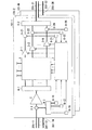
図1は、本発明の一実施形態による光ノード装置101−1〜101−M(Mは1以上の整数)の構成を示すブロック図である。光ノード装置101−1〜101−Mは同様の構成であり、光ノード装置101−1〜101−Mを総称して、又は、いずれかを特定しないときには光ノード装置101と記載する。光ノード装置101−m(mは1以上M以下の整数)は、コア数がN個(Nは2以上の整数)の伝送マルチコアファイバ201−1mから光を入力し、伝送マルチコアファイバ201−2mへ光を出力する。
FIG. 1 is a block diagram showing a configuration of an optical node device 101-1-101-M (M is an integer of 1 or more) according to an embodiment of the present invention. The optical node device 101-1-101-M has the same configuration, and the optical node device 101-1-101-M is generically referred to as an
光ノード装置101は、クロスコネクトスイッチ1と、クラッド励起マルチコア光増幅器2と、コア励起シングルコア光増幅器3−1〜3−Nと、ファンアウト4−1〜4−3と、光分岐器5−1、5−21〜5−2Nと、光パワー検出器6−11〜6−1N、6−21〜6−2Nと、制御器7とを備える。ファンアウト4−1〜4−3は、マルチコアファイバとシングルコアファイバを変換する。
The
光ノード装置101−mの光分岐器5−1は、伝送マルチコアファイバ201−1mから入力した光のパワーを分岐し、クラッド励起マルチコア光増幅器2との間のマルチコアファイバ及びファンアウト4−3との間のマルチコアファイバに出力する。クラッド励起マルチコア光増幅器2は、光分岐器5−1から入力した光を増幅し、ファンアウト4−1との間のマルチコアファイバに出力する。ファンアウト4−1は、光分岐器5−1との間のマルチコアファイバのN個の各コアにより入力した光をそれぞれ、N本のシングルコアファイバに出力する。クロスコネクトスイッチ1は、ファンアウト4−1が出力した光をN本のシングルコアファイバから入力する。クロスコネクトスイッチ1は、各シングルコアファイバから入力した光をそれぞれ光減衰器により個別に減衰し、減衰させた光をそれぞれ波長により分離する。クロスコネクトスイッチ1は、分離した光を、コア励起シングルコア光増幅器3−1〜3−Nそれぞれとの間のシングルコアファイバのうち当該光の出力先に応じたシングルコアファイバに出力する。
The optical turnout 5-1 of the optical node device 101-m branches the power of the light input from the transmission multi-core fiber 201-1m, and joins the multi-core fiber and the fan-out 4-3 with the clad excitation multi-core
コア励起シングルコア光増幅器3−1〜3−Nは、クロスコネクトスイッチ1が出力した光をシングルコアファイバから入力する。コア励起シングルコア光増幅器3−nは、増幅した光を光分岐器5−2nに出力する。光分岐器5−2nは、コア励起シングルコア光増幅器3−nから入力した光のパワーを分岐し、ファンアウト4−2及び光パワー検出器6−2nに出力する。ファンアウト4−2は、光分岐器5−21〜5−2Nが出力した光をそれぞれシングルコアファイバにより入力する。光ノード装置101−mのファンアウト4−2は、N本の各シングルコアファイバから入力した光をそれぞれ、伝送マルチコアファイバ201−2mのN個のコアに入力する。 The core-excited single-core optical amplifiers 3-1 to 3-N input the light output by the cross-connect switch 1 from the single-core fiber. The core-excited single-core optical amplifier 3-n outputs the amplified light to the optical turnout 5-2n. The optical turnout 5-2n branches the power of light input from the core-excited single-core optical amplifier 3-n and outputs it to the fan-out 4-2 and the optical power detector 6-2n. The fan-out 4-2 inputs the light output by the optical turnouts 5-21 to 5-2N by a single core fiber. The fan-out 4-2 of the optical node device 101-m inputs the light input from each of the N single-core fibers to the N cores of the transmission multi-core fiber 201-2 m, respectively.
ファンアウト4−3は、光分岐器5−1との間のマルチコアファイバのN個の各コアにより入力した光をそれぞれ、N本のシングルコアファイバに入力する。光パワー検出器6−11〜6−1Nはそれぞれ、ファンアウト4−3が出力した光をシングルコアファイバから入力する。光パワー検出器6−11〜6−1Nは、入力した光パワーの検出結果を表す信号を制御器7に出力する。一方、光パワー検出器6−2nは、光分岐器5−2nが出力した光をシングルコアファイバから入力する。光パワー検出器6−21〜6−2Nは、入力した光パワーの検出結果を表す信号を制御器7に出力する。制御器7は、光パワー検出器6−11〜6−1N、6−21〜6−2Nにおける検出結果に基づいて、クロスコネクトスイッチ1とコア励起シングルコア光増幅器3−1〜3−Nを制御する。これにより、制御器7は、光ノード装置101における透過利得を制御することができる。
The fan-out 4-3 inputs the light input by each of the N cores of the multi-core fiber to and from the optical turnout 5-1 into the N single-core fibers, respectively. Each of the optical power detectors 6-11 to 6-1N inputs the light output by the fanout 4-3 from the single core fiber. The optical power detectors 6-11 to 6-1N output a signal representing the detection result of the input optical power to the controller 7. On the other hand, the optical power detector 6-2n inputs the light output by the optical turnout 5-2n from the single core fiber. The optical power detectors 6-21 to 6-2N output a signal representing the detection result of the input optical power to the controller 7. The controller 7 uses the cross-connect switch 1 and the core-excited single-core optical amplifiers 3-1 to 3-N based on the detection results of the optical power detectors 6-11 to 6-1N and 6-21 to 6-2N. Control. As a result, the controller 7 can control the transmission gain in the
図2は、図1に示すクロスコネクトスイッチ1の構成を示すブロック図である。同図に示すように、クロスコネクトスイッチ1は、可変光減衰器11−1〜11−Nと、波長選択スイッチ12−11〜12−1N、12−21〜12−2Nとを有する。可変光減衰器11−1〜11−Nは、ファンアウト4−1が出力した光をシングルコアファイバにより入力する。可変光減衰器11−nは、入力した光を制御器7の制御に従って減衰し、波長選択スイッチ12−1nに出力する。波長選択スイッチ12−1nは、可変光減衰器11−nから光を入力して波長ごとに分離する。波長選択スイッチ12−11〜12−1Nは、分離した光を、各波長の光の出力先に従って波長選択スイッチ12−21〜12−2N等に出力する。波長選択スイッチ12−2nは、波長選択スイッチ12−11〜12−1Nから入力した光を合波し、コア励起シングルコア光増幅器3−nに出力する。 FIG. 2 is a block diagram showing the configuration of the cross-connect switch 1 shown in FIG. As shown in the figure, the cross-connect switch 1 has a variable optical attenuator 11-11 to 11-N and wavelength selection switches 12-11 to 12-1N and 12-21 to 12-2N. The variable optical attenuators 11-1 to 11-N input the light output by the fan-out 4-1 through a single core fiber. The variable optical attenuator 11-n attenuates the input light according to the control of the controller 7 and outputs it to the wavelength selection switch 12-1n. The wavelength selection switch 12-1n inputs light from the variable optical attenuator 11-n and separates each wavelength. The wavelength selection switch 12-11 to 12-1N outputs the separated light to the wavelength selection switch 12-21 to 12-2N or the like according to the output destination of the light of each wavelength. The wavelength selection switch 12-2n combines the light input from the wavelength selection switches 12-11 to 12-1N and outputs it to the core excitation single core optical amplifier 3-n.
図3は、図1に示す光ノード装置101−1における一部の経路を抜き出した図である。この経路は、伝送マルチコアファイバ201−11、クラッド励起マルチコア光増幅器2、クロスコネクトスイッチ1、コア励起シングルコア光増幅器3−1、伝送マルチコアファイバ201−21を含む。本図を用いて本実施形態の光ノード装置101による光パワー制御を説明する。
FIG. 3 is a diagram showing a part of the path in the optical node device 101-1 shown in FIG. This path includes a transmission multi-core fiber 201-11, a clad-pumped multi-core
同図に示すクラッド励起マルチコア光増幅器2は、増幅用のマルチコアファイバ21と、増幅用のマルチコアファイバ21に添加された活性イオンを励起する励起光源22と、励起光と信号光を合波又は分波する合分波器23−1、23−2とを備える。マルチコアファイバ21は、ダブルクラッド6コアエルビウム添加ファイバである。励起光源22は、マルチモード980nm帯半導体レーザ(LD)である。合分波器23−1、23−2の光アイソレータ側のファイバはシングルクラッド6コアファイバ、増幅用マルチコアファイバ側のファイバはダブルクラッド6コアファイバ、励起光源側のファイバはシングルクラッドマルチモードである。合分波器23−1、23−2は、レンズ光学系で両マルチコアファイバの対応するコアを結合すると共に、ダイクロイックミラーにより励起光と信号光を合波してマルチコアファイバへ結合させる機能を有している。また、合分波器23−1、23−2は、光アイソレータを内蔵している。
The clad-excited multi-core
同図に示すコア励起シングルコア光増幅器3−1は、増幅用のシングルコアファイバ31と、増幅用のシングルコアファイバに添加された活性イオンを励起する励起光源32−1、32−2と、励起光と信号光を合波又は分波する合分波器33−1、33−2とを備える。本実施形態において、シングルコアファイバ31は、シングルコアエルビウム添加ファイバである。励起光源32−1、32−2は、シングルモード980nm帯半導体レーザ(LD)である。合分波器33−i(i=1,2)は、励起光源32−iからの励起光と信号光とを合波する。合分波器33−1、33−2は、WDMファイバカプラを用いており、光アイソレータが融着接続されている。合分波器33−1、33−2として誘電体多層膜フィルタとレンズにより構成されるバルク型WDMカプラを用いる場合もある。
The core-excited single-core optical amplifier 3-1 shown in the figure includes a single-
光ノード装置101へ入力する信号光及び増幅され出力される信号光は、それぞれその光パワーの一部が光分岐器5−1及び5−21で分岐される。光分岐器5−1において分岐された信号光パワーは、ファンアウト4−3でマルチコアからシングルコアへ変換される。ファンアウト4−3でシングルコアへ変換された光信号パワー及び光分岐器5−21において分岐された信号光パワーはそれぞれ、光パワー検出器6−11及び6−21において光パワーに対応する電気信号(電圧値)に変換され、電気信号が制御器7へ送られる。これらの電気信号はそれぞれ、入力信号光パワー及び出力信号光パワーに1:1で対応した値であり、制御器7ではこれらの電気信号の演算により増幅利得又は出力信号光パワーが所望の値となるように可変光減衰器11−1の減衰量を調整したり、コア励起シングルコア光増幅器3−1のシングルモード980nm帯LDの駆動電流を調整し、980nm帯LDが出力する励起光パワーを増減させたりする。
A part of the optical power of the signal light input to the
図4は、制御器7の動作の一例を示す図である。制御器7は、波長数情報を別途、監視制御チャネル(不図示)から取得する。制御器7は、光パワー検出器6−11における検出値と波長数情報により、単一波長あたり信号光パワーを演算する(ステップS105)。制御器7は、この単一波長あたり信号光パワーに基づき、可変光減衰器11−1〜11−Nの予め設定された減衰量設定値を決定する(ステップS110)。例えば、制御器7は、信号光パワーと減衰量設定値とが対応付けられたルックアップテーブルと補間演算により減衰量設定値を決定することができる。制御器7は、決定した減衰量設定値により、可変光減衰器11−1〜11−Nそれぞれの減衰量を調整する。また、波長選択スイッチ12−11及び12−21は、各信号波長の光パワーを検出する手段を備えており、制御器7は、その検出結果に基づき各信号波長の光パワーを揃えるように、波長選択スイッチ12−11及び12−21における減衰量を調整する(ステップS115)。 FIG. 4 is a diagram showing an example of the operation of the controller 7. The controller 7 separately acquires the wavelength number information from the monitoring control channel (not shown). The controller 7 calculates the signal optical power per single wavelength based on the detected value and the wavenumber information in the optical power detector 6-11 (step S105). The controller 7 determines a preset attenuation set value of the variable optical attenuators 11-1 to 11-N based on the signal light power per single wavelength (step S110). For example, the controller 7 can determine the attenuation set value by a lookup table in which the signal light power and the attenuation set value are associated with each other and an interpolation calculation. The controller 7 adjusts the attenuation amount of each of the variable optical attenuators 11-1 to 11-N according to the determined attenuation amount set value. Further, the wavelength selection switches 12-11 and 12-21 are provided with means for detecting the optical power of each signal wavelength, and the controller 7 arranges the optical power of each signal wavelength based on the detection result. The amount of attenuation in the wavelength selection switches 12-11 and 12-21 is adjusted (step S115).
また、制御器7は、単一波長あたり信号光パワーに基づいて目標利得を算出し(ステップS120)、光パワー検出器6−11の検出結果に基づいて自然放出増幅光(ASE)補正値を算出する(ステップS125)。制御器7は、目標利得に対してASE補正値によりASE補正を行い、PID演算の目標値として設定する(ステップS130)。制御器7は、光パワー検出器6−11及び6−21の検出結果に基づき利得を演算し(ステップS135)、利得の演算結果とPID演算の目標値との偏差に基づくPID演算の結果から(ステップS140)、LD駆動調整値を得る(ステップS145)。制御器7は、得られたLD駆動調整値により、励起光源32−1、32−2であるシングルモード980nm帯LDの駆動電流を調整する。 Further, the controller 7 calculates the target gain based on the signal light power per single wavelength (step S120), and sets the spontaneous emission amplified light (ASE) correction value based on the detection result of the light power detector 6-11. Calculate (step S125). The controller 7 performs ASE correction on the target gain based on the ASE correction value, and sets it as the target value for PID calculation (step S130). The controller 7 calculates the gain based on the detection results of the optical power detectors 6-11 and 6-21 (step S135), and from the result of the PID calculation based on the deviation between the gain calculation result and the target value of the PID calculation. (Step S140), the LD drive adjustment value is obtained (step S145). The controller 7 adjusts the drive current of the single mode 980 nm band LD, which is the excitation light sources 32-1 and 32-2, according to the obtained LD drive adjustment value.
図5は、制御器7の動作の他の例を示す図である。同図において、図4と同一の動作には同一の符号を付している。図4ではステップS125において演算したASE補正値を目標利得の補正に用いているが、図5に示すように、光パワー検出器6−21から得られる出力値に対して補正を行うために用いることも可能である(ステップS205)。制御器7は、光パワー検出器6−21の検出値にASE補正を行った結果と、光パワー検出器6−11の検出値とに基づいて利得を算出する(ステップS210)。制御器7は、ステップS120において算出した目標利得と、ステップS210において算出した利得との偏差を用いてPID演算を行い(ステップS215)、LD駆動調整値を得る(ステップS145)。制御器7は、LD駆動調整値により、シングルモード980nm帯LDの駆動電流を調整する。 FIG. 5 is a diagram showing another example of the operation of the controller 7. In the figure, the same operations as those in FIG. 4 are designated by the same reference numerals. In FIG. 4, the ASE correction value calculated in step S125 is used to correct the target gain, but as shown in FIG. 5, it is used to correct the output value obtained from the optical power detector 6-21. It is also possible (step S205). The controller 7 calculates the gain based on the result of ASE correction of the detected value of the optical power detector 6-21 and the detected value of the optical power detector 6-11 (step S210). The controller 7 performs the PID calculation using the deviation between the target gain calculated in step S120 and the gain calculated in step S210 (step S215), and obtains the LD drive adjustment value (step S145). The controller 7 adjusts the drive current of the single mode 980 nm band LD according to the LD drive adjustment value.
図6は、制御器7の動作のさらに他の例を示す図である。同図において、図4と同一の動作には同一の符号を付している。制御器7は、利得チルト(利得スペクトルの波長に対する傾斜)を補正するように、光パワー検出器6−11の検出結果に基づいて利得チルト補正減衰量を算出する(ステップS305)。制御器7は、利得チルト補正減衰量を、ステップS110と同様に算出したVOA(可変光減衰器)の減衰量設定値に加算(又は減算)する(ステップS310)。これにより、より高精度に利得制御を行うことができる。 FIG. 6 is a diagram showing still another example of the operation of the controller 7. In the figure, the same operations as those in FIG. 4 are designated by the same reference numerals. The controller 7 calculates the gain tilt correction attenuation amount based on the detection result of the optical power detector 6-11 so as to correct the gain tilt (inclination of the gain spectrum with respect to the wavelength) (step S305). The controller 7 adds (or subtracts) the gain tilt correction attenuation amount to the attenuation amount set value of the VOA (variable optical attenuator) calculated in the same manner as in step S110 (step S310). As a result, gain control can be performed with higher accuracy.
図7及び図8は、本実施形態の光ノード装置101の透過利得スペクトル例を示す図である。図7は、WDM信号の単一波長あたりの入力信号光パワーが−10dBmから−20dBmまで変化したときの制御結果を示している。単一波長あたりの入力信号光パワーは、符号A1及び符号B1が−20dBm、符号A2及び符号B2が−17dBm、符号A3及び符号B3が−14dBm、符号A4及び符号B4が−10dBmである。また、符号A1、A2、A3及びA4は、利得チルト補正がない場合であり、符号B1、B2、B3及びB4は、利得チルト補正を行った制御である。いずれの入力信号光パワーにおいても、利得チルト制御がない場合は若干の利得チルトが残るものの、単一波長あたりの光ノード出力信号光パワーは−2dBmに制御できており、利得チルト補正を行った場合は、全信号波長において利得が等しく制御できている。
7 and 8 are diagrams showing an example of a transmission gain spectrum of the
図8は、WDM信号の波長数が異なる信号光入力に対する透過利得スペクトルを示している。黒丸は波長数40のときの各波長の利得値を示し、白丸は波長数1のときのそれぞれの波長における利得値を示している。同図において、波長数1のときのそれぞれの波長における利得値は、波長数40のときの利得値に対して0.2dB以下の範囲にあることがわかる。このことから、本実施形態のマルチコアファイバ光増幅器では入力するWDM信号の波長数が異なっても、それぞれの信号波長においてほぼ一定の利得となるように制御できていることがわかる。 FIG. 8 shows a transmission gain spectrum for signal light inputs having different wavelengths of WDM signals. The black circles indicate the gain values of each wavelength when the wavelength number is 40, and the white circles indicate the gain values at each wavelength when the wavelength number is 1. In the figure, it can be seen that the gain value at each wavelength when the wavelength number is 1 is in the range of 0.2 dB or less with respect to the gain value when the wavelength number is 40. From this, it can be seen that the multi-core fiber optical amplifier of the present embodiment can be controlled so that the gain is substantially constant at each signal wavelength even if the number of wavelengths of the input WDM signal is different.
なお、上述した本実施形態の各光ノード装置101はコア励起シングルコア光増幅器3−1〜3−Nを有しているが、コア励起シングルコア光増幅器3−1〜3−Nに代えて、複数の光ノード装置101で1台のコア励起マルチコア光増幅器を共用して用いることでも同じ効果が得られる。
Although each
ところで、本実施形態の光ノード装置101は、WDM信号波長帯としてC帯(1530〜1565nm)及びL帯(1565〜1625nm)の両方の波長帯に適用できるが、L帯に適用する場合はクラッド励起マルチコア光増幅器2のコア数及び増幅用のマルチコアファイバ21において励起光が伝搬する内側クラッドの半径に制限がある。
By the way, the
図9及び図10は、本実施形態の光ノード装置101をC帯に適用したときのクラッド励起マルチコア光増幅器2のコアの利得変化を示す図である。これらの図は、C帯のクラッド励起マルチコア光増幅器2の一つのコアに着目したとき、他のコアへ入力するWDM信号波長数が全て40〜1へ変化した際に、着目しているコアの利得変化の内側クラッド半径依存性(図9)、及び、コア数依存性(図10)を示している。
9 and 10 are diagrams showing the gain change of the core of the clad-excited multi-core
図11及び図12は、本実施形態の光ノード装置101をL帯に適用したときのクラッド励起マルチコア光増幅器2について、図9及び図10と同様の利得変化を示したものである。図11は、着目しているコアの利得変化の内側クラッド半径依存性を、図12は、コア数依存性を示している。図9及び図10から、C帯では、いずれの条件においても利得変化が0.1dB未満であり、あるコアの利得に着目した場合に他コアの変化の影響は無視できることがわかる。一方で、図11及び図12に示すように、L帯の場合は内側クラッド半径が80μm以下、コア数18超の場合に利得変化が0.2dBとなり、上述した制御に大きな誤差を生じることになる。したがって、増幅用のマルチコアファイバ21の内側クラッド半径やコア数にC帯では特に制限はないものの、L帯では内側クラッド半径が80μm(ミクロン)より大きく、コア数は18以下の制限が必要となることがわかる。
11 and 12 show the same gain changes as in FIGS. 9 and 10 for the clad-excited multi-core
上述した実施形態によれば、光ノード装置は、マルチコア光増幅部と、分離部と、光クロスコネクトスイッチと、複数のシングルコア光増幅部と、出力部と、制御部とを備える。例えば、マルチコア光増幅部はクラッド励起マルチコア光増幅器2であり、分離部はファンアウト4−1であり、光クロスコネクトスイッチはクロスコネクトスイッチ1であり、シングルコア光増幅部はコア励起シングルコア光増幅器3−1〜3−Nであり、出力部はファンアウト4−2であり、制御部は制御器7である。
According to the above-described embodiment, the optical node device includes a multi-core optical amplification unit, a separation unit, an optical cross-connect switch, a plurality of single-core optical amplification units, an output unit, and a control unit. For example, the multi-core optical amplifier unit is a clad-excited multi-core
マルチコア光増幅部は、マルチコアファイバを有し、マルチコアファイバの複数のコアそれぞれを伝送する光を一括して増幅する。マルチコアファイバは、例えば、クラッド励起エルビウム添加ファイバである。分離部は、マルチコアファイバの複数のコアそれぞれを伝送し、増幅された光を、複数の入力側シングルコアファイバそれぞれに入力する。光クロスコネクトスイッチは、複数の入力側シングルコアファイバから入力した光それぞれを光減衰器により個別に減衰した後に波長により分離し、分離した光それぞれを、複数の出力側シングルコアファイバのうち当該光の出力先に応じた出力側シングルコアファイバに出力する。複数のシングルコア光増幅部それぞれは、複数の出力側シングルコアファイバそれぞれを伝送する光を増幅する。出力部は、複数の出力側シングルコアファイバそれぞれを伝送し、増幅された光を、マルチコアファイバの複数のコアそれぞれに出力する。制御部は、マルチコア光増幅部による増幅前の光パワーである入力信号光パワーと、シングルコア光増幅部による増幅後の光パワーである出力光信号パワーとに基づいて、光減衰器及びシングルコア光増幅部を制御する。 The multi-core optical amplification unit has a multi-core fiber, and collectively amplifies the light transmitted through each of the plurality of cores of the multi-core fiber. The multi-core fiber is, for example, a clad-excited erbium-added fiber. The separation unit transmits each of the plurality of cores of the multi-core fiber, and inputs the amplified light to each of the plurality of input-side single-core fibers. The optical cross-connect switch individually attenuates the light input from the plurality of input side single core fibers by an optical attenuator and then separates the separated lights according to the wavelength, and separates the separated light from the plurality of output side single core fibers. Output to the output side single core fiber according to the output destination of. Each of the plurality of single-core optical amplifiers amplifies the light transmitted through each of the plurality of output-side single-core fibers. The output unit transmits each of the plurality of output-side single-core fibers, and outputs the amplified light to each of the plurality of cores of the multi-core fiber. The control unit has an optical attenuator and a single core based on the input signal optical power, which is the optical power before amplification by the multi-core optical amplifier, and the output optical signal power, which is the optical power after amplification by the single-core optical amplifier. Controls the optical amplifier.
制御部は、入力信号光パワーと光の波長数とに基づいて算出した減衰量を用いて光減衰器を制御する。あるいは、制御部は、この算出した減衰量に、入力信号光パワーに基づいて利得チルトの補正を行った結果を用いて光減衰器を制御してもよい。また、制御部は、波長数に基づいて決定した目標利得を入力信号光パワーに基づいて補正し、補正した目標利得と入力信号光パワー及び出力光信号パワーに基づいて得られる利得とに基づいてシングルコア光増幅部を制御する。あるいは、制御部は、出力光信号パワーを入力信号光パワーに基づいて補正し、入力信号光パワー及び補正した出力光信号パワーに基づいて算出した利得と、波長数に基づいて決定した目標利得とに基づいてシングルコア光増幅部を制御してもよい。 The control unit controls the optical attenuator using the amount of attenuation calculated based on the input signal optical power and the wave number of light. Alternatively, the control unit may control the optical attenuator using the result of correcting the gain tilt based on the input signal optical power for the calculated attenuation amount. Further, the control unit corrects the target gain determined based on the number of wavelengths based on the input signal optical power, and based on the corrected target gain and the gain obtained based on the input signal optical power and the output optical signal power. Controls the single core optical amplifier. Alternatively, the control unit corrects the output light signal power based on the input signal light power, and the gain calculated based on the input signal light power and the corrected output light signal power, and the target gain determined based on the number of wavelengths. The single core optical amplification unit may be controlled based on the above.
光クロスコネクトスイッチは、入力側シングルコアファイバそれぞれに対応した複数の光減衰器と、各光減衰器に対応した複数の入力側波長選択スイッチと、出力先に対応した複数の出力側波長選択スイッチとを備えてもよい。例えば、光減衰器は可変光減衰器11−1〜11−Nであり、入力側波長選択スイッチは波長選択スイッチ12−11〜12−1Nであり、出力側波長選択スイッチは波長選択スイッチ12−21〜11−2Nである。光減衰器は、対応する入力側シングルコアファイバから入力した光を減衰させる。入力側波長選択スイッチは、対応する光減衰器において減衰させた光それぞれを波長により分離し、分離した光をそれぞれ当該光の出力先に応じた出力側シングルコアファイバに出力する。出力側波長選択スイッチは、複数の入力側波長選択スイッチから入力した光を合波して、出力先に応じた出力側シングルコアファイバに出力する。制御部は、入力側波長選択スイッチ及び出力側波長選択スイッチにおける各波長の光パワーを揃えるように減衰量を調整する。 The optical cross-connect switch consists of multiple optical attenuators corresponding to each input side single core fiber, multiple input side wavelength selection switches corresponding to each optical attenuator, and multiple output side wavelength selection switches corresponding to the output destination. And may be provided. For example, the optical attenuator is a variable optical attenuator 11-11 to 11-N, the input side wavelength selection switch is a wavelength selection switch 12-11 to 12-1N, and the output side wavelength selection switch is a wavelength selection switch 12-. It is 21-11-2N. The optical attenuator attenuates the light input from the corresponding input side single core fiber. The input side wavelength selection switch separates each of the light attenuated by the corresponding optical attenuator according to the wavelength, and outputs the separated light to the output side single core fiber corresponding to the output destination of the light. The output-side wavelength selection switch combines the light input from the plurality of input-side wavelength selection switches and outputs the light to the output-side single-core fiber according to the output destination. The control unit adjusts the amount of attenuation so that the optical power of each wavelength in the input side wavelength selection switch and the output side wavelength selection switch is the same.
上記のように本実施形態の光ノード装置は、クラッド励起光増幅器と、コア励起光増幅器と、可変光減衰器を備えた光クロスコネクトスイッチとを備え、光ノード装置の入力信号光パワー及び出力光パワーの検出値に基づいてこれらの利得制御を行う。これにより、波長多重された光信号の単一波長あたりの入力信号光パワーの変化があっても、単一波長あたりの出力信号光パワーを一定に制御できる利点を有する。 As described above, the optical node apparatus of the present embodiment includes a clad excitation optical amplifier, a core excitation optical amplifier, and an optical cross-connect switch provided with a variable optical attenuator, and the input signal optical power and output of the optical node apparatus. These gains are controlled based on the detected value of the optical power. This has the advantage that the output signal optical power per single wavelength can be controlled to be constant even if the input signal optical power per single wavelength of the wavelength-multiplexed optical signal changes.
以上、この発明の実施形態について図面を参照して詳述してきたが、具体的な構成はこの実施形態に限られるものではなく、この発明の要旨を逸脱しない範囲の設計等も含まれる。 Although the embodiments of the present invention have been described in detail with reference to the drawings, the specific configuration is not limited to this embodiment, and the design and the like within a range not deviating from the gist of the present invention are also included.
1…クロスコネクトスイッチ
2…クラッド励起マルチコア光増幅器
3−1〜3−N…コア励起シングルコア光増幅器
4−1〜4−3…ファンアウト
5−1、5−21〜5−2N…光分岐器
6−11〜6−1N、6−21〜6−2N…光パワー検出器
7…制御器
11−1〜11−N…可変光減衰器
12−11〜12−1N、12−21〜11−2N…波長選択スイッチ
21…マルチコアファイバ
22…励起光源
23−1、23−2…合分波器
31…シングルコアファイバ
32−1、32−2…励起光源
33−1、33−2…合分波器
101−1〜101−M…光ノード装置
201−11〜201−1M、201−21〜201−2M…伝送マルチコアファイバ
1 ...
Claims (7)
前記マルチコアファイバの複数の前記コアそれぞれを伝送した前記光を、複数の入力側シングルコアファイバそれぞれに入力する分離部と、
複数の前記入力側シングルコアファイバから入力した光それぞれを光減衰器により個別に減衰した後に波長により分離し、分離した前記光それぞれを、複数の出力側シングルコアファイバのうち当該光の出力先に応じた前記出力側シングルコアファイバに出力する光クロスコネクトスイッチと、
複数の前記出力側シングルコアファイバそれぞれに対応し、対応する前記出力側シングルコアファイバを伝送する前記光を増幅する複数のシングルコア光増幅部と、
複数の前記出力側シングルコアファイバそれぞれを伝送した前記光を、伝送マルチコアファイバの複数のコアそれぞれに出力する出力部と、
前記マルチコア光増幅部による増幅前の光パワーである入力信号光パワーと、前記シングルコア光増幅部による増幅後の光パワーである出力光信号パワーとに基づいて前記光減衰器及び前記シングルコア光増幅部を制御する制御部と、
を備える光ノード装置。 A multi-core optical amplifier that has a multi-core fiber and collectively amplifies the light transmitted through each of the plurality of cores of the multi-core fiber.
A separation unit that inputs the light transmitted through each of the plurality of cores of the multi-core fiber to each of the plurality of input-side single-core fibers.
Each of the light input from the plurality of input-side single-core fibers is individually attenuated by an optical attenuator and then separated by wavelength, and each of the separated lights is sent to the output destination of the light among the plurality of output-side single-core fibers. An optical cross-connect switch that outputs to the output side single core fiber according to the above
A plurality of single-core optical amplifiers that correspond to each of the plurality of output-side single-core fibers and amplify the light that transmits the corresponding output-side single-core fibers.
An output unit that outputs the light transmitted through each of the plurality of output-side single-core fibers to each of the plurality of cores of the transmission multi-core fiber.
The optical attenuator and the single-core light are based on the input signal optical power which is the optical power before amplification by the multi-core optical amplifier and the output optical signal power which is the optical power after amplification by the single-core optical amplifier. A control unit that controls the amplification unit and
Optical node device equipped with.
請求項1に記載の光ノード装置。 The control unit controls the optical attenuator using an attenuation calculated based on the input signal light power and the wave number of the light.
The optical node device according to claim 1.
請求項2に記載の光ノード装置。 The control unit controls the optical attenuator using the result of correcting the gain tilt based on the input signal optical power to the calculated attenuation amount.
The optical node device according to claim 2.
請求項1から請求項3のいずれか一項に記載の光ノード装置。 The control unit corrects the target gain determined based on the number of wavelengths of the light based on the input signal light power, and based on the corrected target gain, the input signal light power, and the output light signal power. The single-core optical amplifier is controlled based on the gain obtained.
The optical node device according to any one of claims 1 to 3.
請求項1から請求項3のいずれか一項に記載の光ノード装置。 The control unit corrects the output light signal power based on the input signal light power, and based on the gain calculated based on the input signal light power and the corrected output light signal power, and the number of wavelengths of the light. Control the single-core optical amplification unit based on the target gain determined in
The optical node device according to any one of claims 1 to 3.
複数の前記入力側シングルコアファイバそれぞれに対応し、対応する前記入力側シングルコアファイバから入力した前記光を減衰させる複数の前記光減衰器と、
複数の前記光減衰器それぞれに対応し、対応する前記光減衰器において減衰させた前記光それぞれを波長により分離し、分離した前記光それぞれを当該光の出力先に応じて出力する複数の入力側波長選択スイッチと、
前記出力先それぞれに対応し、複数の前記入力側波長選択スイッチから対応する前記出力先に応じて出力された前記光を合波して、前記出力先に応じた前記出力側シングルコアファイバに出力する複数の出力側波長選択スイッチとを備え、
前記制御部は、前記入力側波長選択スイッチ及び前記出力側波長選択スイッチにおける各波長の光パワーを揃えるように減衰量を調整する、
請求項1から請求項5のいずれか一項に記載の光ノード装置。 The optical cross-connect switch
A plurality of the optical attenuators corresponding to each of the plurality of input-side single-core fibers and attenuating the light input from the corresponding input-side single-core fibers.
A plurality of input sides corresponding to each of the plurality of optical attenuators, separating each of the light attenuated by the corresponding optical attenuator by wavelength, and outputting each of the separated lights according to the output destination of the light. Wavelength selection switch and
Corresponding to each of the output destinations, the light output from the plurality of input side wavelength selection switches according to the corresponding output destinations is combined and output to the output side single core fiber corresponding to the output destinations. Equipped with multiple output side wavelength selection switches
The control unit adjusts the amount of attenuation so that the optical powers of the respective wavelengths in the input side wavelength selection switch and the output side wavelength selection switch are aligned.
The optical node device according to any one of claims 1 to 5.
前記マルチコア光増幅部が有する前記マルチコアファイバは、内側クラッドの半径が80ミクロンより大きくかつコア数が18以下のクラッド励起エルビウム添加ファイバである、
請求項1から請求項6のいずれか一項に記載の光ノード装置。 The wavelength of the light is 1565 nm or more and 1625 nm or less.
The multi-core fiber included in the multi-core optical amplifier is a clad-excited erbium-added fiber having an inner clad radius of more than 80 microns and a core number of 18 or less.
The optical node device according to any one of claims 1 to 6.
Priority Applications (3)
| Application Number | Priority Date | Filing Date | Title |
|---|---|---|---|
| JP2018021429A JP6822988B2 (en) | 2018-02-08 | 2018-02-08 | Optical node device |
| US16/967,691 US10965375B2 (en) | 2018-02-08 | 2019-02-08 | Optical node device |
| PCT/JP2019/004648 WO2019156218A1 (en) | 2018-02-08 | 2019-02-08 | Optical node device |
Applications Claiming Priority (1)
| Application Number | Priority Date | Filing Date | Title |
|---|---|---|---|
| JP2018021429A JP6822988B2 (en) | 2018-02-08 | 2018-02-08 | Optical node device |
Publications (2)
| Publication Number | Publication Date |
|---|---|
| JP2019139029A JP2019139029A (en) | 2019-08-22 |
| JP6822988B2 true JP6822988B2 (en) | 2021-01-27 |
Family
ID=67549497
Family Applications (1)
| Application Number | Title | Priority Date | Filing Date |
|---|---|---|---|
| JP2018021429A Active JP6822988B2 (en) | 2018-02-08 | 2018-02-08 | Optical node device |
Country Status (3)
| Country | Link |
|---|---|
| US (1) | US10965375B2 (en) |
| JP (1) | JP6822988B2 (en) |
| WO (1) | WO2019156218A1 (en) |
Families Citing this family (5)
| Publication number | Priority date | Publication date | Assignee | Title |
|---|---|---|---|---|
| JP6985604B2 (en) * | 2018-02-07 | 2021-12-22 | 日本電信電話株式会社 | Optical node device |
| JP7136319B2 (en) * | 2019-02-22 | 2022-09-13 | 日本電気株式会社 | Optical amplifier and its control method |
| JP7279803B2 (en) * | 2019-09-26 | 2023-05-23 | 日本電信電話株式会社 | optical amplifier |
| JP2021093659A (en) * | 2019-12-11 | 2021-06-17 | 株式会社Kddi総合研究所 | Optical repeater |
| JP7431765B2 (en) | 2021-02-18 | 2024-02-15 | Kddi株式会社 | optical amplifier |
Family Cites Families (11)
| Publication number | Priority date | Publication date | Assignee | Title |
|---|---|---|---|---|
| US6449068B1 (en) * | 2000-03-06 | 2002-09-10 | Lightchip, Inc. | Optical power managed network node for processing dense wavelength division multiplexed optical signals |
| US20030058497A1 (en) * | 2001-09-27 | 2003-03-27 | Nortel Networks Limited | All-optical switching sites for an agile optical network |
| JP3976554B2 (en) * | 2001-11-28 | 2007-09-19 | 富士通株式会社 | Variable attenuator control system |
| US7366370B2 (en) * | 2004-08-20 | 2008-04-29 | Nortel Networks Limited | Technique for photonic switching |
| US7636192B2 (en) * | 2006-06-15 | 2009-12-22 | At&T Corp. | Method, apparatus and system for cost effective optical transmission with fast Raman tilt transient control |
| JP4920489B2 (en) * | 2007-05-16 | 2012-04-18 | 株式会社日立製作所 | Optical add / drop device |
| JP5098807B2 (en) * | 2008-05-22 | 2012-12-12 | 富士通株式会社 | Optical signal adjustment method and optical signal adjustment device |
| JP5321041B2 (en) * | 2008-12-24 | 2013-10-23 | 富士通株式会社 | Optical add / drop multiplexer and WDM transmission method |
| KR20140050674A (en) * | 2011-09-02 | 2014-04-29 | 알까뗄 루슨트 | Method and apparatus for space-division multiplexing systems |
| JP2015510253A (en) * | 2011-12-13 | 2015-04-02 | オーエフエス ファイテル,エルエルシー | Multi-core erbium-doped fiber amplifier |
| US11264776B2 (en) * | 2016-04-21 | 2022-03-01 | Nec Corporation | Optical amplifier, optical network including the same, and method for amplifying optical signal |
-
2018
- 2018-02-08 JP JP2018021429A patent/JP6822988B2/en active Active
-
2019
- 2019-02-08 WO PCT/JP2019/004648 patent/WO2019156218A1/en active Application Filing
- 2019-02-08 US US16/967,691 patent/US10965375B2/en active Active
Also Published As
| Publication number | Publication date |
|---|---|
| WO2019156218A1 (en) | 2019-08-15 |
| US20210036781A1 (en) | 2021-02-04 |
| JP2019139029A (en) | 2019-08-22 |
| US10965375B2 (en) | 2021-03-30 |
Similar Documents
| Publication | Publication Date | Title |
|---|---|---|
| JP6822988B2 (en) | Optical node device | |
| US5995259A (en) | Bidirectional optical telecommunication system comprising a bidirectional optical amplifier | |
| JP7000984B2 (en) | Devices and methods for adjusting the power of wavelength division multiplexing optical signals | |
| WO2020171103A1 (en) | Optical amplifier, and control method therefor | |
| JP5950426B1 (en) | Multi-core optical fiber amplifier | |
| US9641242B2 (en) | Optical communication system, device and method for data processing in an optical network | |
| US9240667B2 (en) | Optical pumping apparatus for few-mode fiber amplification | |
| US8824045B2 (en) | Optical amplifier control apparatus | |
| JP2015167158A (en) | multi-core fiber amplifier | |
| JP2002040495A (en) | Raman amplifier | |
| EP2903185A1 (en) | Optical amplification node for a Spatial Division Multiplexing optical network | |
| Simonneau et al. | 5-Mode amplifier with low modal crosstalk for spatial mode multiplexing transmission with low signal processing complexity | |
| JPH09281532A (en) | Optical amplifier and method as well as optical transmission system having optical amplifier | |
| US20210057869A1 (en) | Optical amplifier and optical amplification method | |
| JP2001094181A (en) | Optical amplifier | |
| JP2008042096A (en) | Optical amplifier and light transmission system | |
| JPWO2018207835A1 (en) | Optical repeater, control method of optical repeater, and optical transmission system | |
| US20230327767A1 (en) | Optical transmission system, and optical transmission method | |
| US11888281B2 (en) | Multimode optical amplifier | |
| EP0915583B1 (en) | Wavelength division multiplex transmission apparatus | |
| CN109952686B (en) | Optical amplifier | |
| CN114865439A (en) | Pump light source, optical amplification system, ROADM, and pump light supply method | |
| JP2009164565A (en) | Gain equalizer, optical amplifier, and optical amplification method | |
| Yan et al. | Experimental investigation on transmission system of dual-polarization mode-division-multiplexing signals with few-mode erbium-doped fiber amplifiers | |
| JP2001223646A (en) | Optical amplification repeater and optical transmitter using the same |
Legal Events
| Date | Code | Title | Description |
|---|---|---|---|
| A621 | Written request for application examination |
Free format text: JAPANESE INTERMEDIATE CODE: A621 Effective date: 20200225 |
|
| TRDD | Decision of grant or rejection written | ||
| A01 | Written decision to grant a patent or to grant a registration (utility model) |
Free format text: JAPANESE INTERMEDIATE CODE: A01 Effective date: 20210105 |
|
| A61 | First payment of annual fees (during grant procedure) |
Free format text: JAPANESE INTERMEDIATE CODE: A61 Effective date: 20210107 |
|
| R150 | Certificate of patent or registration of utility model |
Ref document number: 6822988 Country of ref document: JP Free format text: JAPANESE INTERMEDIATE CODE: R150 |