JP6822823B2 - Lid mechanism, packaging and distribution container - Google Patents
Lid mechanism, packaging and distribution container Download PDFInfo
- Publication number
- JP6822823B2 JP6822823B2 JP2016220361A JP2016220361A JP6822823B2 JP 6822823 B2 JP6822823 B2 JP 6822823B2 JP 2016220361 A JP2016220361 A JP 2016220361A JP 2016220361 A JP2016220361 A JP 2016220361A JP 6822823 B2 JP6822823 B2 JP 6822823B2
- Authority
- JP
- Japan
- Prior art keywords
- distribution
- peripheral wall
- container
- opening
- lid
- Prior art date
- Legal status (The legal status is an assumption and is not a legal conclusion. Google has not performed a legal analysis and makes no representation as to the accuracy of the status listed.)
- Active
Links
- 238000009826 distribution Methods 0.000 title claims description 164
- 238000004806 packaging method and process Methods 0.000 title claims description 18
- 230000002093 peripheral effect Effects 0.000 claims description 130
- 239000000463 material Substances 0.000 claims description 94
- 210000000078 claw Anatomy 0.000 description 23
- 238000007789 sealing Methods 0.000 description 17
- 230000006870 function Effects 0.000 description 11
- 239000007788 liquid Substances 0.000 description 11
- 210000003811 finger Anatomy 0.000 description 10
- LFQSCWFLJHTTHZ-UHFFFAOYSA-N Ethanol Chemical compound CCO LFQSCWFLJHTTHZ-UHFFFAOYSA-N 0.000 description 9
- XLYOFNOQVPJJNP-UHFFFAOYSA-N water Substances O XLYOFNOQVPJJNP-UHFFFAOYSA-N 0.000 description 8
- 238000000926 separation method Methods 0.000 description 7
- 230000000694 effects Effects 0.000 description 6
- 238000001704 evaporation Methods 0.000 description 5
- 238000003780 insertion Methods 0.000 description 5
- 230000037431 insertion Effects 0.000 description 5
- -1 polypropylene Polymers 0.000 description 5
- 230000000844 anti-bacterial effect Effects 0.000 description 4
- 230000007423 decrease Effects 0.000 description 4
- 239000000835 fiber Substances 0.000 description 4
- 239000004615 ingredient Substances 0.000 description 4
- 238000003825 pressing Methods 0.000 description 4
- 239000004698 Polyethylene Substances 0.000 description 3
- 238000013459 approach Methods 0.000 description 3
- 230000008020 evaporation Effects 0.000 description 3
- 238000000465 moulding Methods 0.000 description 3
- 239000004745 nonwoven fabric Substances 0.000 description 3
- 229920000573 polyethylene Polymers 0.000 description 3
- 239000007779 soft material Substances 0.000 description 3
- 229920003002 synthetic resin Polymers 0.000 description 3
- 239000000057 synthetic resin Substances 0.000 description 3
- 229920001169 thermoplastic Polymers 0.000 description 3
- 239000004416 thermosoftening plastic Substances 0.000 description 3
- 239000003795 chemical substances by application Substances 0.000 description 2
- 230000006866 deterioration Effects 0.000 description 2
- 238000012856 packing Methods 0.000 description 2
- 230000036961 partial effect Effects 0.000 description 2
- 238000003860 storage Methods 0.000 description 2
- 210000003813 thumb Anatomy 0.000 description 2
- 229920000742 Cotton Polymers 0.000 description 1
- JOYRKODLDBILNP-UHFFFAOYSA-N Ethyl urethane Chemical compound CCOC(N)=O JOYRKODLDBILNP-UHFFFAOYSA-N 0.000 description 1
- 244000043261 Hevea brasiliensis Species 0.000 description 1
- 125000002066 L-histidyl group Chemical group [H]N1C([H])=NC(C([H])([H])[C@](C(=O)[*])([H])N([H])[H])=C1[H] 0.000 description 1
- 239000004909 Moisturizer Substances 0.000 description 1
- 239000004743 Polypropylene Substances 0.000 description 1
- 229920000297 Rayon Polymers 0.000 description 1
- 239000000853 adhesive Substances 0.000 description 1
- 230000001070 adhesive effect Effects 0.000 description 1
- 230000032683 aging Effects 0.000 description 1
- 150000001298 alcohols Chemical class 0.000 description 1
- 230000002146 bilateral effect Effects 0.000 description 1
- 239000000872 buffer Substances 0.000 description 1
- 229920002678 cellulose Polymers 0.000 description 1
- 239000001913 cellulose Substances 0.000 description 1
- 239000002738 chelating agent Substances 0.000 description 1
- 230000003247 decreasing effect Effects 0.000 description 1
- 230000003111 delayed effect Effects 0.000 description 1
- 238000013461 design Methods 0.000 description 1
- 238000001035 drying Methods 0.000 description 1
- 239000013013 elastic material Substances 0.000 description 1
- 229920001971 elastomer Polymers 0.000 description 1
- 239000003925 fat Substances 0.000 description 1
- 239000003205 fragrance Substances 0.000 description 1
- 238000002347 injection Methods 0.000 description 1
- 239000007924 injection Substances 0.000 description 1
- 230000007794 irritation Effects 0.000 description 1
- 238000010030 laminating Methods 0.000 description 1
- 239000000314 lubricant Substances 0.000 description 1
- 238000004519 manufacturing process Methods 0.000 description 1
- 238000000034 method Methods 0.000 description 1
- 238000002156 mixing Methods 0.000 description 1
- 230000001333 moisturizer Effects 0.000 description 1
- 229920003052 natural elastomer Polymers 0.000 description 1
- 229920001194 natural rubber Polymers 0.000 description 1
- 239000003921 oil Substances 0.000 description 1
- 239000004033 plastic Substances 0.000 description 1
- 229920003023 plastic Polymers 0.000 description 1
- 229920001155 polypropylene Polymers 0.000 description 1
- 239000003755 preservative agent Substances 0.000 description 1
- 230000002335 preservative effect Effects 0.000 description 1
- 239000002964 rayon Substances 0.000 description 1
- 230000002829 reductive effect Effects 0.000 description 1
- 230000001105 regulatory effect Effects 0.000 description 1
- 230000003014 reinforcing effect Effects 0.000 description 1
- 230000000284 resting effect Effects 0.000 description 1
- 230000000717 retained effect Effects 0.000 description 1
- 230000000630 rising effect Effects 0.000 description 1
- 239000005060 rubber Substances 0.000 description 1
- 230000035807 sensation Effects 0.000 description 1
- 229920002379 silicone rubber Polymers 0.000 description 1
- 239000004945 silicone rubber Substances 0.000 description 1
- 230000007928 solubilization Effects 0.000 description 1
- 238000005063 solubilization Methods 0.000 description 1
- 239000002904 solvent Substances 0.000 description 1
- 239000000126 substance Substances 0.000 description 1
- 230000001502 supplementing effect Effects 0.000 description 1
- 229920003051 synthetic elastomer Polymers 0.000 description 1
- 239000005061 synthetic rubber Substances 0.000 description 1
Images


Classifications
-
- B—PERFORMING OPERATIONS; TRANSPORTING
- B65—CONVEYING; PACKING; STORING; HANDLING THIN OR FILAMENTARY MATERIAL
- B65D—CONTAINERS FOR STORAGE OR TRANSPORT OF ARTICLES OR MATERIALS, e.g. BAGS, BARRELS, BOTTLES, BOXES, CANS, CARTONS, CRATES, DRUMS, JARS, TANKS, HOPPERS, FORWARDING CONTAINERS; ACCESSORIES, CLOSURES, OR FITTINGS THEREFOR; PACKAGING ELEMENTS; PACKAGES
- B65D83/00—Containers or packages with special means for dispensing contents
- B65D83/08—Containers or packages with special means for dispensing contents for dispensing thin flat articles in succession
-
- B—PERFORMING OPERATIONS; TRANSPORTING
- B65—CONVEYING; PACKING; STORING; HANDLING THIN OR FILAMENTARY MATERIAL
- B65D—CONTAINERS FOR STORAGE OR TRANSPORT OF ARTICLES OR MATERIALS, e.g. BAGS, BARRELS, BOTTLES, BOXES, CANS, CARTONS, CRATES, DRUMS, JARS, TANKS, HOPPERS, FORWARDING CONTAINERS; ACCESSORIES, CLOSURES, OR FITTINGS THEREFOR; PACKAGING ELEMENTS; PACKAGES
- B65D43/00—Lids or covers for rigid or semi-rigid containers
- B65D43/02—Removable lids or covers
-
- B—PERFORMING OPERATIONS; TRANSPORTING
- B65—CONVEYING; PACKING; STORING; HANDLING THIN OR FILAMENTARY MATERIAL
- B65D—CONTAINERS FOR STORAGE OR TRANSPORT OF ARTICLES OR MATERIALS, e.g. BAGS, BARRELS, BOTTLES, BOXES, CANS, CARTONS, CRATES, DRUMS, JARS, TANKS, HOPPERS, FORWARDING CONTAINERS; ACCESSORIES, CLOSURES, OR FITTINGS THEREFOR; PACKAGING ELEMENTS; PACKAGES
- B65D43/00—Lids or covers for rigid or semi-rigid containers
- B65D43/14—Non-removable lids or covers
- B65D43/16—Non-removable lids or covers hinged for upward or downward movement
-
- B—PERFORMING OPERATIONS; TRANSPORTING
- B65—CONVEYING; PACKING; STORING; HANDLING THIN OR FILAMENTARY MATERIAL
- B65D—CONTAINERS FOR STORAGE OR TRANSPORT OF ARTICLES OR MATERIALS, e.g. BAGS, BARRELS, BOTTLES, BOXES, CANS, CARTONS, CRATES, DRUMS, JARS, TANKS, HOPPERS, FORWARDING CONTAINERS; ACCESSORIES, CLOSURES, OR FITTINGS THEREFOR; PACKAGING ELEMENTS; PACKAGES
- B65D75/00—Packages comprising articles or materials partially or wholly enclosed in strips, sheets, blanks, tubes, or webs of flexible sheet material, e.g. in folded wrappers
- B65D75/52—Details
- B65D75/58—Opening or contents-removing devices added or incorporated during package manufacture
-
- B—PERFORMING OPERATIONS; TRANSPORTING
- B65—CONVEYING; PACKING; STORING; HANDLING THIN OR FILAMENTARY MATERIAL
- B65D—CONTAINERS FOR STORAGE OR TRANSPORT OF ARTICLES OR MATERIALS, e.g. BAGS, BARRELS, BOTTLES, BOXES, CANS, CARTONS, CRATES, DRUMS, JARS, TANKS, HOPPERS, FORWARDING CONTAINERS; ACCESSORIES, CLOSURES, OR FITTINGS THEREFOR; PACKAGING ELEMENTS; PACKAGES
- B65D77/00—Packages formed by enclosing articles or materials in preformed containers, e.g. boxes, cartons, sacks or bags
- B65D77/04—Articles or materials enclosed in two or more containers disposed one within another
Description
本発明は、蓋機構、包装体及び分与容器(収容容器)に関する。 The present invention relates to a lid mechanism, a package, and a distribution container (container).
従来、ウエットティッシュ等のシート材の分与容器は、知られている。例えば、特許文献1には、容器本体と、容器本体の上面にヒンジ部を介して旋回可能に取り付けられた上蓋と、容器本体の上面のうちの凹面部に位置し、上蓋によって開閉される容器開口とを備えたシート材の分与容器が開示されている。
Conventionally, a container for distributing a sheet material such as a wet tissue has been known. For example,
特許文献1に開示された分与容器では、上蓋の内面に配置された環状の突起部を、容器本体の凹面部において容器開口を囲むように位置する溝部に嵌合することによって、容器本体の内部が気密状態となるように上蓋を閉蓋することができる。
In the distribution container disclosed in
しかしながら、製品の運搬中や使用中において、上蓋や容器本体が外部からの衝撃を受けることによって、突起部が溝部から僅かに外れて、外気が中に入り込んでしまうおそれがある。 However, when the product is being transported or used, the upper lid or the container body may receive an impact from the outside, so that the protrusions may be slightly disengaged from the groove and the outside air may enter the inside.
本発明は、従来の蓋機構、包装体及び分与容器の改良であって、外部からの衝撃を受けても、内部の気密状態を維持することのできるシート材の分与容器の提供に関する。 The present invention relates to an improvement of a conventional lid mechanism, a packaging body, and a distribution container, and relates to providing a sheet material distribution container capable of maintaining an airtight state inside even when an external impact is received.
本願の第1発明は、横方向と前後方向と、それらに交差する上下方向とを有し、容器本体と、前記容器本体の頂面壁に位置し、シート材をポップアップ式に取り出すことのできる分与開口を有する分与構造体と、前後端縁を有し、前記後端縁側において前記容器本体にヒンジ部を介して旋回可能に取り付けられ、前記分与開口を気密に閉じることのできる上蓋とを含む蓋機構を備えた前記シート材の分与容器に関する。 The first invention of the present application has a lateral direction, a front-rear direction, and a vertical direction intersecting them, is located on the container body and the top wall of the container body, and can take out the sheet material in a pop-up manner. A distribution structure having a giving opening, and an upper lid having a front and rear end edge, which is rotatably attached to the container body on the rear end edge side via a hinge portion and can close the distribution opening airtightly. The present invention relates to a distribution container for the sheet material provided with a lid mechanism including.
第1発明に係る分与容器は、前記容器本体が、前記分与構造体が配置される凹面部と、少なくとも一部において前記分与開口と連通する容器開口とを有し、前記凹面部には前記容器開口を囲む環状の支持突起が位置し、前記分与構造体は、前記凹面部に固定されるフランジと、前記フランジの内方において上方へ突出する中空の周壁とを有し、前記分与構造体を前記凹面部に配置した状態において、前記支持突起が前記周壁内に位置し、前記上蓋は、内面部から下方へ延びる環状リブを有し、前記上蓋を閉じた状態において、前記環状リブの先端部が前記周壁に当接され、前記分与構造体の前記周壁は頂面を有し、前記周壁内において前記頂面と前記支持突起との間に離間部分が形成されていて、前記離間部分は、前記上下方向において前記環状リブと前記支持突起との間に位置していて、前記横方向において前記環状リブの一部と前記支持突起とが重なって位置していることを特徴とする。 In the distribution container according to the first invention, the container body has a concave surface portion on which the distribution structure is arranged and a container opening that communicates with the distribution opening in at least a part of the concave surface portion. Is located with an annular support projection surrounding the container opening, and the distribution structure has a flange fixed to the concave surface portion and a hollow peripheral wall protruding upward in the inside of the flange. In a state where the distribution structure is arranged on the concave surface portion, the support protrusion is located in the peripheral wall, the upper lid has an annular rib extending downward from the inner surface portion, and the upper lid is closed. The tip of the annular rib is in contact with the peripheral wall, the peripheral wall of the distribution structure has a top surface, and a separated portion is formed between the top surface and the support protrusion in the peripheral wall. The separated portion is located between the annular rib and the support protrusion in the vertical direction, and a part of the annular rib and the support protrusion overlap each other in the lateral direction. It is a feature.
第1発明に係る分与容器の実施態様の一つにおいて、前記支持突起は、前記周壁内に挿入された状態において、前記周壁の内面に当接されている。 In one of the embodiments of the distribution container according to the first invention, the support protrusion is in contact with the inner surface of the peripheral wall in a state of being inserted into the peripheral wall.
かかる分与容器では、支持突起の側面が周壁の内側部分の内面又は外側部分の内面に面状に当接することによって、支持突起と周壁とによる下方シール部のシール機能が向上する。 In such a distribution container, the side surface of the support protrusion comes into surface contact with the inner surface of the inner portion of the peripheral wall or the inner surface of the outer portion, so that the sealing function of the lower sealing portion by the support protrusion and the peripheral wall is improved.
第1発明に係る分与容器の他の実施態様の一つにおいて、前記支持突起は、前記周壁内に挿入された状態において、前記周壁の外側部分の内面に当接されている。 In one other embodiment of the dispensing container according to the first invention, the support projections, in the inserted state to the inner peripheral wall is abutted against the inner surface of the outer portion of the peripheral wall.
かかる分与容器においては、支持突起の側面が周壁の外側部分の内面に面状に当接することによって、支持突起と周壁の内側部分との間に離間部分が形成されるので、該離間部分において上蓋に押圧されて周壁が凹状に変形することができ、より下方シール部のシール機能が向上する。 In such a distribution container, the side surface of the support projection abuts on the inner surface of the outer portion of the peripheral wall in a planar manner to form a separation portion between the support projection and the inner portion of the peripheral wall. The peripheral wall can be deformed in a concave shape by being pressed by the upper lid, and the sealing function of the lower sealing portion is further improved.
かかる分与容器では、周壁の平坦状の頂面に上蓋の下方に延出する部分が当接された状態において、周壁が凹状に変形して分与開口と上蓋との空間を気密にする上方シール部が形成される。 In such a distribution container, in a state where the portion extending below the upper lid is in contact with the flat top surface of the peripheral wall, the peripheral wall is deformed in a concave shape to make the space between the distribution opening and the upper lid airtight. A seal portion is formed.
第1発明に係る分与容器のさらに他の実施態様の一つにおいて、前記周壁の頂面が平坦状である。 In one of still other embodiments of the distribution container according to the first invention, the top surface of the peripheral wall is flat.
かかる分与容器では、上蓋の下方へ延出する部分を安定して当接することができる。 In such a distribution container, the portion extending downward of the upper lid can be stably brought into contact with the portion.
かかる分与容器では、環状リブの先端が周壁に当接されることによって、上方シール部のシール機能を向上させることができる。 In such a distribution container, the sealing function of the upper sealing portion can be improved by bringing the tip of the annular rib into contact with the peripheral wall.
第1発明に係る分与容器のさらに他の実施態様の一つにおいて、前記環状リブは、内側リブと前記内側リブを囲む外側リブとを有し、前記内側リブが前記外側リブよりも下方へ延出しており、前記上蓋の閉じた状態において、前記外側リブが前記周壁の前記頂面に当接され、前記内側リブが前記周壁の内側に位置する。 In still one embodiment of the distribution container according to the first invention, the annular rib has an inner rib and an outer rib surrounding the inner rib, and the inner rib is below the outer rib. In the extended state of the upper lid, the outer rib is in contact with the top surface of the peripheral wall, and the inner rib is located inside the peripheral wall.
かかる分与容器では、外側リブが周壁に当接することによって上方シール部が形成されるとともに、内側リブが周壁の内側に位置することによって、周壁が内方へ倒伏して下方シール部のシール機能が低下するのを防止することができる。 In such a distribution container, the outer rib abuts on the peripheral wall to form an upper seal portion, and the inner rib is located inside the peripheral wall so that the peripheral wall falls inward to seal the lower seal portion. Can be prevented from decreasing.
第1発明に係る分与容器のさらに他の実施態様の一つにおいて、前記環状リブは、前記上蓋の前記前後端縁側の部分に比べて、それらの間に位置する両側部分の方が下方に延出している。 In still one embodiment of the distribution container according to the first invention, the annular ribs are lower on both side portions located between them than on the front and rear edge side portions of the upper lid. It is extended.
かかる分与容器では、前後端縁側において、外側リブが周壁に当接して気密状態が維持される一方、内側リブが周壁に当接されることなく、上蓋を開けやすくなる。 In such a distribution container, the outer ribs abut on the peripheral wall to maintain an airtight state on the front and rear edge sides, while the inner ribs do not abut on the peripheral wall, making it easier to open the upper lid.
第1発明に係る分与容器のさらに他の実施態様の一つにおいて、前記分与開口は、前記後端縁側に位置して前記横方向及び前記前後方向へ拡がる第1孔部と、前記横方向における前記第1孔部のほぼ中央部から連なって前記前端縁側へ延びる第2孔部とから形成され、前記第1孔部の前記横方向における寸法は前記第2孔部の前記横方向における寸法よりも大きくなっている。 In one further embodiment of the dispensing container according to the first invention, wherein the dispensing opening has a first hole portion located on the rear edge side extends to the transverse direction and the longitudinal direction, the transverse It is formed from a second hole portion that is continuous from the substantially central portion of the first hole portion in the direction and extends toward the front end edge side, and the lateral dimension of the first hole portion is the lateral direction of the second hole portion. It is larger than the size.
かかる分与容器では、第1孔部が比較的に大きな開口面積を有することから、最初のシート材を引き出すときに分与開口の開口縁部を破断することなく、指先を容易に挿入することができるとともに、2枚目以降のシート材を取り出す場合には、比較的に幅狭の第2孔部から引き出すことによって、開口縁部に接触するときの摩擦抵抗によって、シート材が連続的に引き出されるのを抑制することができる。 In such a distribution container, since the first hole has a relatively large opening area, the fingertip can be easily inserted without breaking the opening edge of the distribution opening when the first sheet material is pulled out. When the second and subsequent sheet materials are taken out, the sheet material is continuously pulled out from the relatively narrow second hole due to the frictional resistance when it comes into contact with the opening edge. It can be suppressed from being pulled out.
第1発明に係る分与容器のさらに他の実施態様の一つにおいて、前記分与構造体は、前記周壁の内方に位置する内蓋部と、前記内蓋部の内方に位置する内側フラップとを有し、前記内側フラップは前記第2孔部の開口縁部に位置する高剛性域を除いて前記内蓋部よりも剛性が低く、前記高剛性域は前記内蓋部と同等の剛性を有する。 In still one embodiment of the distribution container according to the first invention, the distribution structure has an inner lid portion located inside the peripheral wall and an inner lid portion located inside the inner lid portion. The inner flap has a flap and is lower in rigidity than the inner lid portion except for a high rigidity region located at the opening edge portion of the second hole portion, and the high rigidity region is equivalent to the inner lid portion. Has rigidity.
かかる分与容器では、内側フラップの剛性が低く可撓性を有することによって、分与開口からシート材を取り出すときに指先が触れても刺激を感じることはなく、また、第2孔部の開口縁部に高剛性域が位置することによって、シート材に対する摩擦抵抗を高めて確実にシート材を1枚ずつ引き出すことができる。 In such a distribution container, since the inner flap has low rigidity and flexibility, no irritation is felt even if the fingertip touches the sheet material when it is taken out from the distribution opening, and the opening of the second hole portion. By locating the high-rigidity region at the edge portion, the frictional resistance to the sheet material can be increased and the sheet material can be reliably pulled out one by one.
第1発明に係る分与容器のさらに他の実施態様の一つにおいて、前記分与構造体は、前記周壁の内方に位置する内蓋部を有し、前記内蓋部は上方へ隆起するようなドーム状を有する。 In still another embodiment of the distribution container according to the first invention, the distribution structure has an inner lid portion located inside the peripheral wall, and the inner lid portion rises upward. It has a dome shape like this.
かかる分与容器では、容器開口と分与開口との間に内部空間が形成されて、シート材を引き出すときに、容器開口と分与開口とのそれぞれにおいてシート材に摩擦抵抗を与えることができる。 In such a distribution container, an internal space is formed between the container opening and the distribution opening, and when the sheet material is pulled out, frictional resistance can be given to the sheet material at each of the container opening and the distribution opening. ..
本願の第2発明は、前記分与容器の前記容器本体内に収められる包装体である。 The second invention of the present application is a package to be housed in the container body of the distribution container.
第2発明に係る包装体の実施態様の一つにおいて、前記分与容器の前記容器本体内に収められ、支持面の内面に止着可能なシール部を備える。 In one of the embodiments of the package according to the second invention, a seal portion that is housed in the container body of the distribution container and can be fixed to the inner surface of the support surface is provided.
かかる包装体では、シール部を介して支持面の内面に貼付されることによって、包装体開口と容器開口とが密接し、シート材に含まれる揮発成分が揮発するのを抑制することができる。 In such a package, the opening of the package and the opening of the container are brought into close contact with each other by being attached to the inner surface of the support surface via the seal portion, and it is possible to prevent the volatile components contained in the sheet material from volatilizing.
本願の第3発明は、横方向と前後方向とを有し、それらに交差する上下方向とを有し、機構本体と、前記機構本体の頂面壁に位置し、シート材をポップアップ式に取り出すことのできる分与開口を有する分与構造体と、前後端縁を有し、前記後端縁側において容器本体にヒンジ部を介して旋回可能に取り付けられ、前記分与開口を気密に閉じることのできる上蓋とを含む蓋機構に関する。 The third invention of the present application has a lateral direction and a front-rear direction, has a vertical direction intersecting them, is located on the mechanism main body and the top wall of the mechanism main body, and takes out the sheet material in a pop-up manner. It has a distribution structure having a distribution opening that can be formed, and has front and rear end edges , and is rotatably attached to the container body via a hinge portion on the rear end edge side, so that the distribution opening can be closed airtightly. The present invention relates to a lid mechanism including an upper lid.
第3発明に係る蓋機構は、前記機構本体は、前記分与構造体が配置される凹面部と、少なくとも一部において前記分与開口と連通する機構開口とを有し、前記凹面部には前記機構開口を囲む環状の支持突起が位置し、前記分与構造体は、前記凹面部に固定されるフランジと、前記フランジの内方において上方へ突出する中空の周壁とを有し、前記分与構造体を前記凹面部に配置した状態において、前記支持突起が前記周壁内に位置し、前記上蓋は、内面部から下方へ延びる環状リブを有し、前記上蓋を閉じた状態において、前記環状リブの先端部が前記周壁に当接され、前記分与構造体の前記周壁は頂面を有し、前記周壁内において前記頂面と前記支持突起との間に離間部分が形成されていて、前記離間部分は、前記上下方向において前記環状リブと前記支持突起との間に位置していて、前記横方向において前記環状リブの一部と前記支持突起とが重なって位置していることを特徴とする。 In the lid mechanism according to the third invention, the mechanism main body has a concave surface portion on which the distribution structure is arranged and a mechanism opening that communicates with the distribution opening in at least a part of the concave surface portion. An annular support protrusion surrounding the mechanism opening is located, and the distribution structure has a flange fixed to the concave surface portion and a hollow peripheral wall protruding upward in the flange, and the distribution structure has the same portion. In a state where the given structure is arranged on the concave surface portion, the support protrusion is located in the peripheral wall, the upper lid has an annular rib extending downward from the inner surface portion, and when the upper lid is closed, the annular shape is formed. The tip of the rib is in contact with the peripheral wall, the peripheral wall of the distribution structure has a top surface, and a separated portion is formed between the top surface and the support protrusion in the peripheral wall. The separated portion is located between the annular rib and the support protrusion in the vertical direction, and is characterized in that a part of the annular rib and the support protrusion overlap each other in the lateral direction. And.
本願の第4発明は、前記蓋機構における、前記機構本体に止着可能なシール部を備えた包装体である。 The fourth invention of the present application is a package of the lid mechanism provided with a seal portion that can be fastened to the mechanism body.
本発明に係る蓋機構、包装体及び分与容器は、分与構造体を容器本体の凹面部に配置した状態において、凹面部の支持突起が中空の周壁内に位置していることによって、周壁を支持してそれが倒伏するのを防止し、上蓋と周壁とからなる上方シール部と周壁と支持突起とからなる下方シール部とによる環状シール部によって内部の気密状態を維持することができる。 The lid mechanism, the package body, and the distribution container according to the present invention have a peripheral wall because the support protrusion of the concave surface portion is located in the hollow peripheral wall in a state where the distribution structure is arranged on the concave surface portion of the container body. It is possible to maintain an airtight state inside by supporting an upper seal portion including an upper lid and a peripheral wall and an annular seal portion formed by a peripheral wall and a lower seal portion including a support projection.
図面は、本発明の特定の実施の形態を示し、発明の不可欠な構成ばかりでなく、選択的及び好ましい実施の形態を含む。
図1−16を参照して、本発明に係る蓋機構、包装体及び分与容器として、蓋機構2、積層されたシート材9を含む包装体90及びそれを収める分与容器(収容容器)10を例にとり、本発明の詳細を実施形態に基づいて説明すると以下のとおりである。以下の実施形態は、発明の不可欠な構成ばかりではなく、選択的及び好ましい実施の形態を含む。シート材9は、水やアルコール等の液体成分を含浸させたウエットティッシュのほかに、フロアや身体を拭浄するためのウエットシートを含む。
With reference to FIGS. 1-16, as the lid mechanism, the packaging body and the distribution container according to the present invention, the
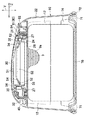
図1〜5を参照すると、分与容器10は、横方向Xと前後方向Zと、それらに交差する上下方向Yとを有し、シート材9が積層された状態で包装された包装体90を収容する容器本体20と、容器本体20の上面にヒンジ部5を介して旋回可能に取り付けられた上蓋30と、容器本体20の底に着脱可能に取り付けられた底蓋70とを含む。容器本体20は、着脱可能な底蓋70を外すことによって、包装体90を収めることができる。また、上蓋30の前端部は、ラッチ機構によって操作ボタン80に係止されており、操作ボタン80を押圧することによって、ラッチ31による係止が解除されて、方向Pへ旋回して開いた状態となる(図2参照)。
Referring to FIGS. 1 to 5, the
容器本体20は、中空のボックス形状であって、外周縁から中心へ向かって上方へ緩やかに隆起した形状をなす頂面壁21と、周壁22とを有する。容器本体20及び底蓋70は、射出成形が可能であって、例えばポリプロピレンやポリエチレン等の熱可塑性合成樹脂によって形成される。容器本体20の周壁22の内面には、その強度を高めるための補強リブ12が配置されている。
The
図2,8を参照すると、容器本体20の頂面壁21には、横方向Xの中央部において下方へ凹んだ凹面部23が位置する。凹面部23は、後記の分与構造体(パッキン部材)50を支持する支持面(内底面)24と、支持面24を囲んで頂面壁21まで延びる内周壁面25とを有する。支持面24は、その中央に位置する円形の容器開口26と、容器開口26を囲むように上方へ突出する環状の支持突起27とを有する。内周壁面25は中央部分から前方へ向かって次第に高さ寸法(上下方向Yにおける寸法)が小さくなっており、内周壁面25の前端部分の内面側には、上蓋30のラッチを受けるラッチ受け部(キーパー)を備えた操作ボタン80が配置されている。
Referring to FIGS. 2 and 8, a
凹面部23は、内周壁面25よりも高さ寸法の小さな後端部分を有する。後端部分は段差状であって、その横方向Xの中央部において後方へ凹となる凹状部分28が位置し、凹状部分28を介して横方向Xに対向する対向内側面には、上蓋30の軸部45の両端が嵌挿される凹状の軸受け部23aが形成されている。
The
図8,図11(a),(b)を参照すると、支持突起27の近傍外側には、各係合爪40が配置されている。各係合爪40は、互いに離間した第1爪41及と第2爪42とを有し、第1爪41と第2爪42との間には離間部分43が形成されている。係合爪40は、第1爪41と第2爪42とが外力で互いに弾性的に接近又は接触可能な軟質の熱可塑性合成樹脂によって形成されている。係合爪40の各爪41,42は、頭部41a,42aと、頸部41b,42bとを有する。
With reference to FIGS. 8, 11 (a) and 11 (b), each engaging
図2,3,9,10を参照すると、容器本体20の凹面部23には、容器本体20を上蓋30によって気密に蓋止するための分与構造体50が配置されている。分与構造体50は、上下面50A,50Bと、外周に位置する剛性のフランジ51と、フランジ51の内方に連なる可撓性の周壁52と、周壁52の内周に連なる剛性の内蓋部(外側域)53と、内蓋部53の内周に連なり分与開口54を画定する可撓性の内側フラップ(内側域)55とを有している。分与構造体50の下面においては、周壁52と内蓋部53の外周縁部との間において下方へ環状に延びる下方突起56が位置している。
Referring to FIGS. 2, 3, 9 and 10, a
本実施形態において、分与構造体50は、軟質材料、例えば、軟質ポリエチレン、ウレタン、シリコンゴム等から一体的に成形されており、シート材9にアルコール成分を含浸させた場合においては、好ましくは、シート材9に含まれるアルコール成分の気散・蒸発やアルコール成分による分与構造体50を形成する材料の変質を抑えるために、軟質ポリエチレンから形成されている。分与構造体50は、同質の材料から形成されているが、厚さ寸法を調整することによって、可撓性のある部分と比較的に剛性の高い部分とを有している。また、異質の材料から形成することもでき、例えば、ダブルモールディング(二色成形)によって、1つの金型内において可撓性のある部分に弾性材料、剛性のある部分に熱可塑性合成樹脂をそれぞれ用いて、一体的に形成することもできる。
In the present embodiment, the
分与開口54は、平面視において略T字形ないし略銀杏形であって、曲状の前端縁54aと、後方側において横方向Xへ延びる後端縁54bと、前後端縁54a、54b間において、前方へ向うにつれて次第に互いに近づくように湾曲した形状を有する一対の両側縁54cとを有する。分与開口54は、さらに、後方に位置して横方向X及び前後方向Zへ拡がる第1孔部(指挿入部)57と、横方向Xにおける第1孔部57の中央部分から連なって前方へ延びる第2孔部58とを有する。第2孔部58は、前方へ向かうにつれて次第に括れた形状を有し、最も幅狭になる部分からさらに前端縁54aまで延びる部分は、最も幅狭となる部分(最狭部分)に比べて僅かに幅広となっている。最狭部分がそれよりも幅広の部分の間に位置することによって、最狭部分をシート材9が通過するときに両側縁部54aを上下方向Yに撓み易くすることができ、シート材9が両側縁部54aに引っ掛かって引き出し難くなるのを防ぐことができる。分与開口54がスリットではなくこのように比較的に大きな開口から形成されていても、後記のシール部によって内部の空間を気密に維持することができる。また、分与開口54は、第1孔部57と第2孔部58とが互いに交差する限りにおいて、T字状のほかに、十字状や放射状であってもよい。
The
図10(b)を参照すると、内蓋部53の厚さ寸法D1が内側フラップ55の厚さ寸法D2よりも大きくなっており、内蓋部53は内側フラップ55に比べて肉厚であるといえる。また、内側フラップ55のうちの第2孔部58を形成する開口縁部分には、内側フラップ55の他の部分に比べて肉厚であって、内蓋部53の厚さ寸法D1とほぼ同じ厚さ寸法D3を有する高剛性域59が位置する。また、分与構造体50の内蓋部53は、上方へ隆起するようなドーム状を有する。
Referring to FIG. 10B, the thickness dimension D1 of the
フランジ51は、容器本体20の係合爪40に係合される係合孔51aを有している。係合孔51aは、分与開口54に対して周壁52の外側に4つ配置されている。各係合孔51aは、上方側に位置する円形の大径部51bと、下方側に位置する円形の小径部51cとを有する。フランジ51の後端縁部の中央には、切欠51eが形成されている。
The
ここで、分与容器10は、蓋機構2をさらに有する。蓋機構2は、図1及び図2において仮想線で囲んだ領域であって、上蓋30と、内周壁面25とそれに囲まれた支持面24と分与構造体50とを含む機構本体3から構成されている。本実施形態においては、機構本体3は、分与容器10の一部を区分して形成するものであるが、他の実施例として図17において示すように、包装体90に直接取り付けられる独立した蓋体(キャップ)であってもよい。かかる他の実施例においても、後記のマウス構造、密閉構造及びヒンジ構造を有するものであって、機構本体3が本実施形態のように容器本体20の一部から形成されている場合と同様の技術的構成並びにそれによる技術的効果を奏することができる。
Here, the
<密閉構造>
図11(a),(b)を参照して、分与構造体50を容器本体20の凹面部23に取り付ける方法について述べると、まず、横方向X及び前後方向Zにおいて、4つの係合孔51aの位置と4つの係合爪40の位置とがそれぞれ合致するように、凹面部23に分与構造体50が配置される。係合孔51aの小径部51cの径方向の寸法N1は、係合爪40の先端部における第1爪41及び第2爪42の外周面の径方向の寸法N2よりも小さいために、分与構造体50が支持面24へ押し付けられると、小径孔51cを通過するときに第1爪41の頭部41aと第2爪42の頭部42aとが小径孔51cの内周に当接されることによって、弾性変形して互いに接近する。
<Sealed structure>
With reference to FIGS. 11 (a) and 11 (b), a method of attaching the
さらに、分与構造体50を下方へ向かって移動させて凹面部23に押し付けることによって、頭部41a,41bが大径孔51bに移動して、大径孔51bと小径孔51cとの間に位置する段差51dと頭部41a,42aの下端とが上下方向Yにおいて対向位置し、係合爪41が係合孔51から離脱するような下方への移動が規制される。また、係合爪41が係合孔51に係止された状態において、支持突起27が周壁52の内部空間に進入して周壁52の頂面52aと支持突起27との間には離間部分29が形成される。このように、係合爪40が係合孔51aに嵌挿されることによって、取付部において分与構造体50が容器本体20に安定的に取り付けられる。
Further, by moving the
図7を参照すると、上蓋30は、前後端縁30a,30bと、前後端縁30a,30bをつなぐ両側縁30cとによって外形をなす略扁平矩形状であって、前端縁部の横方向Xにおける中央部にはラッチ31が位置し、後端縁30bの横方向Xにおける中央部には下方へ屈曲して延びる連結部32が位置している。上蓋30は、分与容器10の外面の一部を形成する外面と、容器本体20の凹面部23と対向する内面と、内面から凹面部23に向かって下方へ延びる環状リブ33とをさらに有する。なお、本明細書において、上蓋30が開いた状態とは、上蓋30が容器本体20の頂面壁21に対して約90度起立した状態を意味し、上蓋30が閉じた状態とは、上蓋30が開いた状態から凹面部23に向かって旋回方向Pへ旋回し、ラッチ31がボタン部材80に係止された状態を意味する。
With reference to FIG. 7, the
環状リブ33は、円形の内側リブ34と、内側リブ34の外周縁を囲むように位置する円形の外側リブ35とを有する。内側リブ34は、外側リブ35よりもその高さ寸法(上下方向Y)の寸法が大きくなっている。
The
図5を参照すると、上蓋30の外面は、後方から前方へ向かって次第に下り勾配となる流線形状をなし、前方部分はその横方向Xにおける中央部分が下方へ湾曲して凹んでいる。また、閉蓋した状態において、上蓋30の前方に位置する操作ボタン80の上面が中央へ向かって僅かに窪んだ略弓状であり、上蓋30と操作ボタン80とは連続した流線形状をなすので、使用者が指先で上蓋30及び操作ボタン80の外面に触れたときの触感が良好である。また、それらの外面が平面状である場合に比べて、意匠性に優れる。さらに、乳幼児等のおしめを交換するときなどに、母親等の使用者は、乳幼児が目を覚まさないように比較的に暗がりの部屋で分与容器10からシート材9を取り出すことが想定されるが、かかる場合において、使用者が指先で閉じた状態の上蓋30の外面をなぞるように触れることによって、前方へ下り勾配となった行き着く先に操作ボタン80が位置することを触感によって認識することができる。したがって、このように、操作ボタン80が直接視認できない状況下においても、スムーズに開閉操作を行うことができる。
Referring to FIG. 5, the outer surface of the
図4−6を参照すると、上蓋30をヒンジ部5を介して凹面部23側へ旋回して閉蓋した状態において、上蓋30の内面に位置する外側リブ35が分与構造体50の周壁52の頂面52aに当接される。このように、互いに当接される外側リブ(環状リブ)35と周壁52とが一体となって、分与開口54を囲繞する上方シール部7が形成される。また、上蓋30の内周面が分与開口54と対向する天井部分を形成することから、上方シール部7と天井部分とによって分与開口54の上方には気密性のある空間S1が画成され、シート材9に含まれる液体が蒸発するのを効果的に防止することができる。
Referring to FIG. 4-6, in a state where the
また、凹面部23の支持突起27は、分与構造体50の中空の周壁52内に位置している。周壁52は中空であるから変形容易であって、上蓋30の動きに対する追従性に優れるとともに、その内部に支持突起27が位置することによって、周壁52が完全に倒伏してしまうことはなく、周壁52が完全に倒伏して上蓋30と分与構造体50との間に隙間が生じて、上方シール部7のシール効果が大きく低下することはない。
Further, the
また、支持突起27の先端は周壁52の頂面52aの内面の下方に位置していることによって、周壁52の頂面52aと支持突起27の先端との間には離間部分(離間スペース)29が形成されている。周壁52の頂面52aが位置する上端は、それに当接される上蓋30の外側リブ35に上方から押圧されることによって変形可能である。上方シール部7がかかる構成を有することによって、上蓋30が閉じた状態において、外側リブ35が周壁52の上端を凹状に変形させることによって、内側リブ34が周壁52の頂面52aによって囲まれた状態となる。
Further, since the tip of the
このように、周壁52の上端が変形することによって上方シール部7のシール機能が向上するものであって、例えば、上蓋30が外部からの衝撃を受けて、外側リブ35に対して分与構造体50の周壁52からその径方向の内側又は外側へ位置ずれするような力が作用されても、外側リブ35によって周壁52を押し込もうとする力が離間部分29によって逃がすことによって位置ずれし難くなり、かつ、外側リブ35が周壁52の上端に食い込むような態様で当接されていることから、容器本体20内の気密状態を維持することができる。また、周壁52内に支持突起27が位置することによって、周壁52の頂面52aが外側リブ35によって凹状に大きく変形されても、支持突起27が周壁52を介して間接的にそれを押し込む外側リブ35と当接されるので、周壁52全体が変形してシール機能が低下するおそれはない。
In this way, the sealing function of the upper sealing portion 7 is improved by deforming the upper end of the
ここで、支持突起27は、周壁52の内部空間に挿入されているのみではなく、その側面が周壁52の内側部分の内面52c又は外側部分の内面52dに面状に当接されていることが好ましい。かかる場合には、容器本体20内をより気密にして、外部からの空気の進入を効果的に抑制することができる。さらに、図6に示すとおり、支持突起27が、周壁52の内部空間に挿入され、かつ、周壁52の外側部分の内面52dに当接していることがさらに好ましい。かかる態様の場合には、支持突起27と周壁52の内側部分の内面52cとの間に離間部分が形成されるので、外側リブ35によって押圧されて変形する周壁52の先端が該離間部分へ撓むことができ、分与構造体50は、パッキンとしてより高いシール機能を発揮しうる。
Here, the
図6を参照すると、このように、蓋機構2は、分与構造体50の周壁52と上蓋30の環状リブ33とが当接されることによって内部空間S1を気密にする上方シール部7と、支持突起27が周壁52の内側部分の内面52c又は外側部分の内面52dに面状に当接することによって内部空間S1を気密にする下方シール部8とからなる環状シール部を有する。蓋機構2が両方のシール部7,8を有することによってより確実に内部空間S1を気密とすることができる。
With reference to FIG. 6, in this way, the
また、環状リブ33の内側リブ34は、周壁52の内方に位置している。環状リブ33が2重の内外側リブ34,35から形成されることによって、環状リブ33が1重のリブから形成される場合に比して、上蓋30と容器本体20との間に位置する空間内の空気の流れが複雑化して空気が内部に滞留して外部への流出が遅延するので、上方シール部7のシール機能を向上させることができる。また、内側リブ34が周壁52の内側に位置して、その頂面52aよりも下方に延びていることによって、周壁52の内方への倒伏を防止することができる。また、環状リブ33は、上蓋30の前後端縁30a,30b側の部分に比べて、それらの間に位置する両側部分の方が下方に延出している。周壁52がかかる形状を有することによって、ヒンジ部5の位置する後端縁30b側とボタン部材80の位置する前端縁30a側とにおいて外側リブ35が周壁52に当接して気密状態が維持される。また、内側リブの上下方向Yにおける寸法が大きい場合には、上蓋30は前方へ下り勾配となる形状を有しているので、内側リブ34が周壁52に当接してしまい上蓋を開け難くなるおそれがあるが、前端縁30a側において比較的に上下方向Yにおける寸法を小さくすることによって内側リブ34が周壁52に当接されることはなく、上蓋30を開けやすくなる。なお、周壁52は後端縁30b側から前端縁30a側へ次第に上下方向の寸法が小さくなっており、上蓋30を閉じるときに最初に周壁52に外側リブ35が当接される後端縁30b側において外側リブ3が周壁52と最も強く当接してそれを変形させている。
Further, the
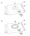
図12(a),(b)は、それぞれ、包装体90の実施例の一例を示すものである。図12(a)を参照すると、本実施例においては、包装体90は、拭浄用のウエットシートやウエットティッシュ等の複数のシート材9と、シート材9を包被する包装シート91と、包装シート91からシート材9を取り出すための包装体開口92と、包装体開口92を閉塞し、包装体90の上面に貼付した封印シール(図示せず)とを有している。包装体90は、不透液性のプラスチック製であって、内部のシート材に含浸された液体(水、アルコール、薬剤等)が蒸発するのを防止する。
12 (a) and 12 (b) show an example of an embodiment of the
図12(b)を参照すると、本実施例においては、包装体90の包装体開口92の開口縁部に粘着剤が塗布されたシール部93が配置されている。かかる包装体90は、シール部93を支持面24の内面に貼り付けることによって、容器開口26と包装体開口92とを上下方向Yにおいて重なるように配置することができる。このような配置態様によって、包装体90がアルコール成分等の液体成分を含浸した複数のシート材9を含む場合において、容器開口26と包装体開口92とが離間しているときに比べてシート材9の乾燥を抑制することができる。
With reference to FIG. 12B, in this embodiment, the sealing
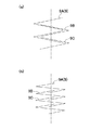
図13(a),(b)には、包装体90内におけるシート材9の積層態様の一例を模式的に示すが、実際のシート材は上下方向Yにおいて互いに当接するように積層されている。図13(a)を参照すると、1枚のシート材9は、横方向X又は前後方向Zのいずれか一方で1回折り曲げて2つ折りのV字状にして、二つ折りしたシート材9を上下方向Yで積層されている。
13 (a) and 13 (b) schematically show an example of the stacking mode of the
図13(b)を参照すると、1枚のシート材9は、横方向X又は前後方向Zのいずれか一方で2回折り曲げて三つ折りのZ字状にし、その三つ折りしたシート材を上下方向Yへ積層してもよい。図示した積層態様のいずれにおいても、最上のシート材9Aを包装体開口92から引き上げることによって、次のシート材9Bの一部が引き上げられ、順次、一枚ずつシート材9を引き出すことができる。このように、シート材9が、包装体開口92を通過して容器開口26からいわゆるポップアップ式に取り出される積層構造を有する限りにおいて、図示した態様のほかに各種公知の積層態様を採用しうる。なお、シート材9は、折り曲げられた端部が分与開口54に近接して位置した方が引き出しやすいので、横方向Xへ折り曲げられていることが好ましい。
Referring to FIG. 13B, one
<マウス構造>
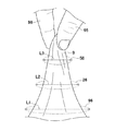
図2,4,14を参照すると、分与容器10からシート材9を取り出すときには、まず、包装体90の包装体開口92を開封した状態で底蓋70の内面に載置し、底蓋70を容器本体20に取り付ける。次に、容器本体20の操作ボタン80を押圧して上蓋30を開いた状態において、分与開口54の第1孔部57に親指95と人指し指(又は中指)96を挿し入れて、包装体90において最も上方に位置するシート材9A、すなわち、包装体開口92から一部が露出している最上のシート材9Aを摘持する。
<Mouse structure>
With reference to FIGS. 2, 4 and 14, when taking out the
このとき、第1孔部57は、横方向X及び前後方向Zへ拡がった形状であって、操作者の親指95と人指し指96等の少なくとも2本の指が挿入できる程度の大きさを有していることから、分与開口54の開口縁部を形成する内側フラップ55を無理やりに拡げて破断したりすることなく、スムーズに指を挿入してシート材9Aを取り出すことができる。第1孔部57は、このように所要の大きさの開口面積を有することから、このままシート材9Aを引き出すと、開口縁部による摩擦抵抗が作用せず、次のシート材9Bがつられて全部引き出されてしまうおそれがある。
At this time, the
そこで、操作者が、第1孔部57から最初のシート材9Aの一部を引き出すと同時に、第1孔部57に比して幅狭の第2孔部58に摺動させながら移動させることによって、シート材9Aが第2孔部58によって挟持される。かかる状態において、最初のシート材9Aを引き上げて取り出すと、第2孔部58による摩擦抵抗によって、次のシート材9Bの一部が第2孔部58から露出した状態となる。シート材9は、上下方向Yにおいて交互に重なるように配置されていることから、以降順次、第2孔部58からスムーズに取り出すことができる。このように、第1孔部57は、最初のシート材9Aを引き出すときに少なくとも2本の指先95,96を挿入するための指挿入用の開口であって、包装体の2枚目以降のシート材9Bを引き出すときには使用されない。
Therefore, the operator pulls out a part of the
図14を参照すると、分与構造体50が容器本体20に取り付けられた状態において、包装体90の包装体開口92の一部、容器開口26の一部及び分与開口54の一部は、互いに上下方向Yにおいて(分与容器10の平面視において)重なって位置している。包装体90の包装体開口92の横方向Xにおける寸法L1は、容器本体20の容器開口26の横方向Xにおける寸法L2よりも大きく、容器開口26の横方向Xにおける寸法L2は、分与構造体50の分与開口54における第2孔部58の横方向Xにおける寸法L3よりも大きくなっている。
Referring to FIG. 14, in a state where the
したがって、各開口26,58,92は、上下方向Yにおいて少なくとも一部が連通しており、それらの横方向Xにおける寸法(幅寸法)L1−L3は下方から上方へ次第に小さくなっており、各寸法L1−L3の大きさの相関関係は、包装体90の横方向Xにおける寸法L1≧容器開口26の横方向における寸法L2≧分与開口54の第2孔部58の横方向Xにおける寸法L3となっている。なお、各開口26,58,92は、図示したほかに、円形、楕円形、矩形等の各種公知の形状を採用することができるものであって、各開口26,58,92における横方向Xの寸法L1−L3は、各種形状における各開口26,58,92における横方向Xの最大寸法を意味する。
Therefore, at least a part of the
このように、包装体開口92、容器開口26及び分与開口54の第2孔部58は、下方から上方へ向かって次第にその幅寸法L1−L3が小さくなっていることから、包装体開口92から引き出されたシート材9は、容器開口26、第2孔部58を通過することによって次第に狭められている。それによって、各開口92,26,58の縁部と摺接して上方へ向かうにつれて次第に大きな摩擦抵抗を受け、シート材9が連続的に引き出されるのを効果的に抑制することができ、優れた分与効果を発揮することができる。
As described above, the width dimensions L1-L3 of the
上下方向Yにおいて少なくとも一部が連通する各開口92,26,58による摩擦抵抗によってシート材9を分与するためには、各開口92,26,54が上下方向Yにおいて離間している必要がある。本実施形態においては、分与構造体50が容器本体20とは別体から形成されていることによって、容器開口26と分与開口54との間に空間S2が形成されることから、容器開口26の後にさらに分与開口54における摩擦抵抗によってシート材9を確実に分与できるようにしている。また、分与構造体50の内蓋部53は、上方へ隆起するようなドーム状を有するので、それが平坦状である場合に比べて、容器開口26と分与開口54との間により大きな空間S2を形成して、分与開口54においてより確実に摩擦抵抗を付与することができる。
In order to distribute the
また、図12(b)に示す包装体90の場合には、包装体開口92の周縁にシール部93が位置し、容器本体20の支持面24の内面にシール部93を貼り付けた状態で包装体90を容器本体20内に収容する。かかる場合には、包装体開口92と容器開口26とが上下方向Yにおいて離間せずに連続した開口を形成することから、包装体開口92と容器開口26とが離間することによってシート材9のアルコール成分等の液体成分が蒸発するのを抑制することができる。かかる場合であっても、容器開口26の上方にそれよりも幅狭の第2孔部58が位置することによって、シート材9を分与することができる。
Further, in the case of the
さらに、支持面24がゴム等の軟質材料から形成されてその内面が起伏した形状である場合には、包装体90の包装体開口92の縁部に位置するシール部を安定して貼り付けることができない。本実施形態においては、容器本体20に直接に軟質材料から形成された開口縁部によって画成された狭窄部(分与開口)を形成していないことから、包装体開口92の周縁に位置するシール部を硬質材料から形成され、かつ、平滑な支持面24の内面に安定的に貼り付けることができる。
Further, when the
分与容器10の平面視において、包装体開口92は、分与開口54の第1孔部57側ではなく、第2孔部58側に位置していることが好ましく、少なくともその一部が第2孔部58と上下方向Yにおいて重なることが好ましい。包装体開口92が、第2孔部58側に位置することによって、2枚目以降のシート材9をスムーズに第2孔部58から引き出すことができる。
In a plan view of the
また、第2孔部58の開口縁部には高剛性域59が位置しており、所要の強度を有するので、複数回においてシート材9を摺接させて引き出したとしても、その一部が変形したり破断したりするのを抑制することができる。また、肉薄の内側フラップ55に比して肉厚の高剛性域59が位置することによって、シート材9に対して比較的に高い摩擦抵抗を与えることができる。
Further, since the
分与開口54の周縁部に位置する内側フラップ55は、柔軟性/可撓性を有し、内蓋部53の剛性よりも内側フラップ55の剛性が小さいので、最初のシート材9Aを取り出すときに、指95,96が比較的に剛性の高い内面部23に当たって刺激を感じるのを防止することができる。また、分与構造体50の外周縁部には、剛性の高いフランジ51が位置することによって、外周縁部の変形が抑制される。
The
<ヒンジ構造>
図2,7,16を参照すると、上蓋30は、蓋体から下方へ屈曲して延出する連結部32において、その下端の両側から延出する一対の軸部(旋回軸の両端)45と、各軸部45が挿入される、凹面部23の後端部分に位置する軸受け部23aとによるヒンジ部(ヒンジ構造)5によって、開口26,54を開閉可能に旋回することができる。凹面部23と上蓋30との間には、上下方向Yへ延びる帯状のばね部材36が配置されている。ばね部材36は、合成ゴムや天然ゴムで形成された弾性帯片であって、上蓋30はばね部材36によってそれが開く方向へばね付勢されている。ばね部材36は、強度を向上させるために好ましくはその長さ方向へ複数折り重ねられているとともに、その長さ方向における一端36Aと他端36Bとを有し、両端36A,36Bには挿通孔が位置している。
<Hinge structure>
Referring to FIGS. 2, 7 and 16, the
ばね部材36は、上蓋30の内面のうちの連結部32の上方に位置する突起37に一端36Aの挿通孔を挿通することによって上蓋30に取り付けられ、他端36Bの挿通孔を凹面部23の支持面24から上方へ突出する突起38に挿通することによって容器本体20に取り付けられることによって、蓄勢状態にある。また、ばね部材36の他端36Bは、分与構造体50のフランジ51と凹面部23の支持面24との間において挟持されていることからさらに安定して容器本体20に取り付けられており、上蓋30の開閉操作を繰り返しても容器本体20から外れてしまうことはない。また、ばね部材36の一方端36Aは、上蓋30の突起37が位置する部分を被覆するカバー部材39によって上蓋30にさらに安定的に固定されている。なお、ばね部材36には、図示例に代えて、コイルスプリング等の慣用のばね材料を用いることもできる。
The
例えば、従来の分与容器において、上蓋の両側縁から外方へ突起する一対の軸部とそれらに対向する軸受け部とによって上蓋が旋回可能に軸支された態様からなるヒンジ構造が採用されている。かかるヒンジ構造においては、分与容器の横方向の略中央部に位置するばね部材から軸受け部までの離間距離が比較的に大きいために、ばね部材の反撥力の影響を蓋自体や容器本体が受けてしまう。したがって、分与容器を比較的に高い室温を有する室内に長時間放置した場合、ばね部材の反撥力に抗することができずに上蓋の一部が熱変形してしまい、その結果、旋回したときに分与容器と摺接して開閉し難くなってしまったり、軸部が軸受け部から外れて開閉できなくなってしまうおそれがある。 For example, in a conventional distribution container, a hinge structure is adopted in which the upper lid is rotatably supported by a pair of shaft portions protruding outward from both side edges of the upper lid and bearing portions facing them. There is. In such a hinge structure, since the separation distance from the spring member located at the substantially central portion in the lateral direction of the distribution container to the bearing portion is relatively large, the lid itself and the container body are affected by the repulsive force of the spring member. I will receive it. Therefore, when the distribution container is left in a room having a relatively high room temperature for a long time, the repulsive force of the spring member cannot be resisted and a part of the upper lid is thermally deformed, resulting in rotation. Occasionally, it may become difficult to open and close due to sliding contact with the distribution container, or the shaft portion may come off the bearing portion and cannot be opened or closed.
本実施形態においては、凹面部23の後端部分のうちの横方向Xの中央に位置する凹状部分28には、両側に軸部45を有する連結部32の下端部が配置されている。したがって、軸部45間の横方向Xの寸法(離間寸法)L5は、上蓋30の横方向の寸法L4よりも小さくなっており、ばね部材36と軸部45との離間距離が比較的に小さくなるので、ばね部材36の反撥力の影響を蓋自体が受けて熱変形することはないので、分与容器10を比較的に高温の室内に長時間放置したとしても、ヒンジ機能が失われることはない。
In the present embodiment, the lower end portion of the connecting
また、本実施形態におけるヒンジ構造においては、上蓋30の開閉操作を繰り返し行うことによって、前方へ凸となるように屈曲したばね部材36が経時変化(軟化)によって次第に後方へ向かって折れ曲がり、その一部が連結部32の下端と凹面部23との間の隙間49に挟み込まれてしまうことがある。
Further, in the hinge structure of the present embodiment, by repeatedly opening and closing the
本実施形態においては、支持面24の凹状部分28には、ばね部材36の後方への移動を規制するための移動規制手段98が設けられている。移動規制手段98は、凹状部分28において突起38よりも後方側に位置する突起から形成されている。ばね部材36の後方に移動規制手段98が設けられていることから、ばね部材36が経時変形によって後方へ屈曲したとしても後方への移動が規制され、その一部が連結部32の下端と凹面部23との間の隙間49に入り込んでしまうことはない。
In the present embodiment, the
さらに、上蓋30は、その両側縁部が容器本体20に固定されていないことから、開いた状態において、上端縁30aから下端縁30bまで延びる蓋本体全体が、容器本体20の後面(背面)よりも後方に位置している。したがって、容器本体20の凹面部23が外部に露出せず、上蓋30と容器本体20との間に段差が形成されないので、外観においてすっきりとした印象を与えることができる。また、容器本体20の凹面部23の後面は、僅かに上方へ突出する突出部分を有し、突出部分によって上蓋30と容器本体20との間の隙間が被覆されるので、上蓋30が閉じた状態であっても、分与容器10は外観においてすっきりとした印象を与えることができる。
Further, since both side edges of the
再び、図3−5を参照すると、操作ボタン80は、中央に向かって窪む上面(指当て面)を有するベース81と、ベース81から下方へ延びるフレーム状のばね部82とを有する。ばね部82の後方には、凹面部23の前方部分に位置する軸受け孔23bに嵌挿される軸部(取り付け軸)83が配置されている。また、ベース81の後方には被係止突起84が配置されており、開蓋状態から上蓋30を旋回して前端縁30aに位置するラッチ31を操作ボタン80の被係止突起84に係止される。上蓋30が閉じられてラッチ機構によってロックされた状態において、ばね部82による付勢に抗して操作ボタン80を押圧することによって、ラッチ31が被係止突起84から外れて、上蓋30が旋回して開いた状態になる。
With reference to FIG. 3-5 again, the
操作ボタン80は、軸部83を中心にして旋回するものであるところ、軸部83の下方にばね部82が位置する場合には、ばね部82を圧縮するときにばね部82に対して下方へ向かう力と横方向Xへずれる力とが必要となるので、比較的に強い力で押圧する必要がある。本実施形態においては、軸部83の下方にばね部82が配置されておらず、前後方向Zにおいて対向するように位置していることによって、押圧力が直接的にばね部82に作用させることができるので、比較的に小さい力で開閉操作を行うことができる。
The
図2,15を参照すると、底蓋70は、底面から起立する外周壁71と、外周壁71よりも上方へ延出する内周壁72と、内外周壁71,72の間に位置する、容器本体20の下端が挿入される溝73と、内周壁72の四隅からさらに上方へ延びる支持凸部74とを有する。支持凸部74は、平坦な頂面を有する断面略台形状であって、容器本体20の隅部の内面と摺動させることによって位置合わせして底蓋70を容器本体20に取り付けることができるので、挿入ガイドとして機能しうる。
Referring to FIGS. 2 and 15, the
また、包装体90は、底蓋70の支持凸部74に支持された状態で分与容器10に収容することができる。例えば、図12(b)に示すような、包装体開口92を囲むように位置するシール部93を有する包装体90の場合には、容器本体20の支持面24の内面に貼付した状態で収容するが、かかる場合において、支持凸部74に包装体90が載置されることで、より安定的に容器本体20に収容することができる。また、支持凸部74は、平坦な頂面を有していることによって、収容容器内において安定して包装体90を支持することができる。
Further, the
底蓋70の隅部(四隅)の外面(外周壁71の外面)には、外方へ突出する薄板状の操作リブ75が位置している。分与容器10の組立状態において、底蓋70の内周壁72の外周面全体が容器本体20の内面に当接された状態であって、容器本体20内が気密であることから、外気との気圧差によって底蓋70が外れ難くなっている。また、使用者が、曲状の外周壁71の外面を指で摘まんで容器本体20から離間する方向へ底蓋70を引っ張ろうとしても指先が滑ってしまって力を上手く伝達することができない。本実施形態においては、底蓋70の隅部の外面に操作リブ75が位置しているので、操作リブ75を摘持して又はそれに指先を引っ掛けて底蓋70を引っ張ることによって容易に容器本体20から取り外すことができる。
On the outer surface (outer surface of the outer peripheral wall 71) of the corners (four corners) of the
また、容器本体20と底蓋70とを容易に分離することができるように、支持凸部74及び/又はそれと接する容器本体20の周壁22の内面に滑剤を塗布したり、シボ加工を施す等して摩擦を低減する加工を施してもよい。かかる場合には、操作リブ75を引っ張ったときに底蓋70が容器本体20からより外れやすくなるとともに、製造工程において複数の容器本体20を積み重ねた状態において、個々に分離しやすくなる。なお、操作リブ75は、操作の便宜上、底蓋70の四隅にそれぞれ配置されているが、少なくとも隅部に配置されていればよい。
Further, in order to easily separate the
本実施形態において、分与構造体50と容器本体20とは別体で形成されているが、二色成形によって一体的に形成することもできる。ただし、分与構造体50を別体に形成することによって、ばね部材36の他端36Bを支持面24との間に抑えることができるとともに、経時劣化によって一部が破断、変形してマウス構造、密閉構造が上手く機能することができなくなった場合でも、新しい分与構造体50に交換することによって、機能させることができる。
In the present embodiment, the
<他の実施の形態>
図17は、他の実施の形態における蓋機構2の斜視図である。本実施形態にかかる蓋機構2の基本構成は、図1−図16に記載の蓋機構2の基本構成と同様であって、同一の構成要素については同一の符号を使用しており、相違する点についてのみ以下に説明する。
<Other embodiments>
FIG. 17 is a perspective view of the
本実施形態において、蓋機構2は、横方向Xと前後方向Zと、それらに交差する上下方向Yとを有し、包装体90の上面にシール部93を介して直接に取り付けられた機構本体3を含む。機構本体3は、その頂面壁121の凹面部23に配置され、シート材9をポップアップ式に取り出すことのできる分与開口54を有する分与構造体50と、前後端縁30a,30bと、後端縁30b側において機構本体3にヒンジ部5を介して旋回可能に取り付けられ、分与開口54を気密に閉じることのできる上蓋30とを含む。
In the present embodiment, the
かかる実施例においても、分与構造体50の周壁52と上蓋30とによる上方シール部7と周壁52と支持突起27とによる下方シール部8とからなる環状シール部によって上蓋30と分与開口54との間における空間を気密にすることができる。また、容器開口26と分与開口54との間に空間が形成され、分与開口54が第1孔部57と第2孔部58とからなるマウス構造を有することから優れた分与効果を発揮することができる。
Also in such an embodiment, the
本発明におけるシート材9について補足すると、シート材9は、対象物の汚れの拭き取りや対象物に含浸した液体を付着させることを目的として、シート材料や含浸される液体を適宜自由に選択して使用することができるものであって、例えば、水を主とした液体成分の場合には、水を含んで保持することができるセルロース系繊維を主とした繊維不織布、例えば、レーヨン、パルプ、コットンの単体又はこれらを含む繊維を所定の割合で配合してなるスパンレース繊維不織布、エアレイド繊維不織布をシート材料として好適に用いることができる。
Supplementing the
また、シート材9に含浸される液体成分としては、基剤として、水、アルコール類又は油脂成分、基剤の補助成分として、製品の品質を維持するための防腐剤、汚れを落とすための活性剤や溶剤成分、殺菌・抗菌作用を与えるための殺菌・抗菌成分、肌に良好な効果を与えるための保湿剤や薬効成分、香料、液体成分を安定させるためのキレート剤や緩衝剤、可溶化剤等を用いることができる。なお、シート材9の液体成分の基剤として水を使用した場合には、シート材9どうしが水の表面張力によって互いにくっついた状態となるので、引き出すときに分与開口54によって適正な摩擦抵抗を与える必要がある。一方、シート材9の基剤としてアルコール成分を用いた場合には、シート材どうしを比較的容易に分離することができ、その揮発性を考慮して、密閉した状態で保管する必要があり、本発明における環状シール部のような内部を気密するための構造を要する。したがって、本発明に係る容器10は、シート材9の基剤が水又はアルコール成分のいずれであってもその分与・収容容器として使用することができる。
The liquid component impregnated in the
蓋機構2、包装体90及び分与容器10をそれぞれ構成する部材には、特に明記されていない限りにおいて、本明細書に記載されている材料のほかに、この種の分野において通常用いられている公知の材料を制限なく用いることができる。また、本明細書において使用されている「第1」及び「第2」等の用語は、同様の要素、位置等を単に区別するために用いてある。
Unless otherwise specified, the members constituting the
2 蓋機構
3 機構本体
5 ヒンジ部
9,9A,9B シート材
10 分与容器
20 容器本体
21 頂面壁
23 凹面部
24 支持面
26 容器開口
27 支持突起
30 上蓋
30a 上蓋の前端縁
30b 上蓋の後端縁
32 連結部
33 環状リブ
34 内側リブ
35 外側リブ
50 分与構造体
51 フランジ
52 周壁
52c 周壁の内側部分の内面
52d 周壁の外側部分の内面
53 内蓋部
54 分与開口
55 内側フラップ
57 第1孔部
58 第2孔部
59 高剛性域
X 横方向
Y 上下方向
Z 前後方向
2 Lid mechanism 3
Claims (13)
前記容器本体は、前記分与構造体が配置される凹面部と、少なくとも一部において前記分与開口と連通する容器開口とを有し、
前記凹面部には前記容器開口を囲む環状の支持突起が位置し、
前記分与構造体は、前記凹面部に固定されるフランジと、前記フランジの内方において上方へ突出する中空の周壁とを有し、
前記分与構造体を前記凹面部に配置した状態において、前記支持突起が前記周壁内に位置し、
前記上蓋は、内面部から下方へ延びる環状リブを有し、前記上蓋を閉じた状態において、前記環状リブの先端部が前記周壁に当接され、
前記分与構造体の前記周壁は頂面を有し、前記周壁内において前記頂面と前記支持突起との間に離間部分が形成されていて、
前記離間部分は、前記上下方向において前記環状リブと前記支持突起との間に位置していて、前記横方向において前記環状リブの一部と前記支持突起とが重なって位置していることを特徴とする分与容器。 A distribution structure having a lateral direction, a front-rear direction, and a vertical direction intersecting them, located on the container body and the top wall of the container body, and having a distribution opening capable of popping out the sheet material. A lid mechanism including a body and an upper lid which has front and rear edge edges , is rotatably attached to the container body on the rear edge side via a hinge portion, and can airtightly close the distribution opening. A container for distributing the sheet material.
The container body has a concave portion on which the distribution structure is arranged, and at least a part of the container opening that communicates with the distribution opening.
An annular support protrusion surrounding the container opening is located on the concave surface portion.
The distribution structure has a flange fixed to the concave surface portion and a hollow peripheral wall protruding upward in the flange.
In a state where the distribution structure is arranged on the concave surface portion, the support protrusion is located in the peripheral wall .
The upper lid has an annular rib extending downward from the inner surface portion, and in a state where the upper lid is closed, the tip end portion of the annular rib is brought into contact with the peripheral wall.
The peripheral wall of the distribution structure has a top surface, and a separated portion is formed between the top surface and the support projection in the peripheral wall.
The separated portion is located between the annular rib and the support protrusion in the vertical direction, and is characterized in that a part of the annular rib and the support protrusion overlap each other in the lateral direction. Distributing container.
前記機構本体は、前記分与構造体が配置される凹面部と、少なくとも一部において前記分与開口と連通する機構開口とを有し、
前記凹面部には前記機構開口を囲む環状の支持突起が位置し、
前記分与構造体は、前記凹面部に固定されるフランジと、前記フランジの内方において上方へ突出する中空の周壁とを有し、
前記分与構造体を前記凹面部に配置した状態において、前記支持突起が前記周壁内に位置し、
前記上蓋は、内面部から下方へ延びる環状リブを有し、前記上蓋を閉じた状態において、前記環状リブの先端部が前記周壁に当接され、
前記分与構造体の前記周壁は頂面を有し、前記周壁内において前記頂面と前記支持突起との間に離間部分が形成されていて、
前記離間部分は、前記上下方向において前記環状リブと前記支持突起との間に位置していて、前記横方向において前記環状リブの一部と前記支持突起とが重なって位置していることを特徴とする蓋機構。 It has a lateral direction and a front-rear direction, and has a vertical direction intersecting them, and has a mechanism main body and a distribution opening located on the top wall of the mechanism main body and capable of popping out the sheet material. In a lid mechanism including a distribution structure and an upper lid which has front and rear end edges and is rotatably attached to the container body on the rear end edge side via a hinge portion and can airtightly close the distribution opening. ,
The mechanism body has a concave portion on which the distribution structure is arranged and a mechanism opening that communicates with the distribution opening at least in part.
An annular support protrusion surrounding the mechanism opening is located on the concave surface portion.
The distribution structure has a flange fixed to the concave surface portion and a hollow peripheral wall protruding upward in the flange.
In a state where the distribution structure is arranged on the concave surface portion, the support protrusion is located in the peripheral wall .
The upper lid has an annular rib extending downward from the inner surface portion, and in a state where the upper lid is closed, the tip end portion of the annular rib is brought into contact with the peripheral wall.
The peripheral wall of the distribution structure has a top surface, and a separated portion is formed between the top surface and the support projection in the peripheral wall.
The separated portion is located between the annular rib and the support protrusion in the vertical direction, and is characterized in that a part of the annular rib and the support protrusion overlap each other in the lateral direction. The lid mechanism.
Priority Applications (5)
| Application Number | Priority Date | Filing Date | Title |
|---|---|---|---|
| JP2016220361A JP6822823B2 (en) | 2016-11-11 | 2016-11-11 | Lid mechanism, packaging and distribution container |
| KR1020197016480A KR102446738B1 (en) | 2016-11-11 | 2017-08-21 | Lid devices, packages and dispensing containers |
| PCT/JP2017/029809 WO2018087980A1 (en) | 2016-11-11 | 2017-08-21 | Lid mechanism, packaging body, and dispensing container |
| CN201780057753.8A CN109715524B (en) | 2016-11-11 | 2017-08-21 | Lid mechanism, package, and dispensing container |
| TW106129888A TWI732929B (en) | 2016-11-11 | 2017-09-01 | Lid mechanism, packaging body and dispensing container |
Applications Claiming Priority (1)
| Application Number | Priority Date | Filing Date | Title |
|---|---|---|---|
| JP2016220361A JP6822823B2 (en) | 2016-11-11 | 2016-11-11 | Lid mechanism, packaging and distribution container |
Publications (3)
| Publication Number | Publication Date |
|---|---|
| JP2018076109A JP2018076109A (en) | 2018-05-17 |
| JP2018076109A5 JP2018076109A5 (en) | 2019-03-28 |
| JP6822823B2 true JP6822823B2 (en) | 2021-01-27 |
Family
ID=62110573
Family Applications (1)
| Application Number | Title | Priority Date | Filing Date |
|---|---|---|---|
| JP2016220361A Active JP6822823B2 (en) | 2016-11-11 | 2016-11-11 | Lid mechanism, packaging and distribution container |
Country Status (5)
| Country | Link |
|---|---|
| JP (1) | JP6822823B2 (en) |
| KR (1) | KR102446738B1 (en) |
| CN (1) | CN109715524B (en) |
| TW (1) | TWI732929B (en) |
| WO (1) | WO2018087980A1 (en) |
Families Citing this family (7)
| Publication number | Priority date | Publication date | Assignee | Title |
|---|---|---|---|---|
| KR101968898B1 (en) * | 2018-07-31 | 2019-04-15 | (주) 우수컨버팅 | Bracket for taking wet tissue off |
| JP2020040676A (en) * | 2018-09-06 | 2020-03-19 | 明星産商株式会社 | Face pack package |
| JP7176688B2 (en) * | 2018-10-24 | 2022-11-22 | ニプロ株式会社 | Chemical impregnated sheet |
| JP7266494B2 (en) * | 2019-08-13 | 2023-04-28 | 株式会社シマノ | cooler box |
| KR200494136Y1 (en) * | 2019-11-08 | 2021-08-11 | 변용필 | Cap of tissue case |
| JP7014833B2 (en) * | 2020-02-14 | 2022-02-01 | 大王製紙株式会社 | Household tissue paper storage container |
| JP7204699B2 (en) * | 2020-03-12 | 2023-01-16 | ユニ・チャーム株式会社 | wet wipe container |
Family Cites Families (15)
| Publication number | Priority date | Publication date | Assignee | Title |
|---|---|---|---|---|
| FR2340852A1 (en) * | 1976-02-13 | 1977-09-09 | Huret Jacques | FRONT DERAILLEUR CHAIN GUIDE FOR BICYCLES |
| JPH08143072A (en) * | 1994-11-22 | 1996-06-04 | Dainippon Printing Co Ltd | Structure of outlet of wet-tissue container |
| TW356128U (en) * | 1998-09-14 | 1999-04-11 | Yonyu Plastics Co Ltd | Structure for can cap |
| US6523690B1 (en) | 2000-03-30 | 2003-02-25 | Kimberly-Clark Worldwide, Inc. | Wet wipe container with flexible orifice |
| JP4338342B2 (en) * | 2001-12-07 | 2009-10-07 | ユニ・チャーム株式会社 | Container with lid |
| JP4279028B2 (en) * | 2003-03-31 | 2009-06-17 | 大王製紙株式会社 | Wet sheet container |
| US20050011906A1 (en) * | 2003-07-15 | 2005-01-20 | Kimberly-Clark Worldwide, Inc. | Storing and dispensing container for product |
| US7806292B2 (en) * | 2006-02-28 | 2010-10-05 | Joseph S Kanfer | Towelette dispenser |
| JP4864666B2 (en) * | 2006-11-30 | 2012-02-01 | 大王製紙株式会社 | Wet tissue storage container and packing structure of wet tissue storage container |
| JP5258522B2 (en) * | 2008-11-14 | 2013-08-07 | ユニ・チャーム株式会社 | Wet tissue package storage container |
| JP5512116B2 (en) * | 2008-11-14 | 2014-06-04 | ユニ・チャーム株式会社 | Openable / closable container |
| US8844745B2 (en) * | 2010-08-30 | 2014-09-30 | Kimberly-Clark Worldwide, Inc. | Dispenser with a wide lid-activation button having a stabilizing rib |
| WO2016043188A1 (en) * | 2014-09-17 | 2016-03-24 | 大日本印刷株式会社 | Cover opening and closing structure, and dispensing vessel in which said structure is used |
| JP5981977B2 (en) * | 2014-09-17 | 2016-08-31 | 大日本印刷株式会社 | Lid opening / closing structure and storage container using the structure |
| JP5830193B1 (en) * | 2015-06-30 | 2015-12-09 | ユニ・チャーム株式会社 | Wet tissue storage container |
-
2016
- 2016-11-11 JP JP2016220361A patent/JP6822823B2/en active Active
-
2017
- 2017-08-21 CN CN201780057753.8A patent/CN109715524B/en active Active
- 2017-08-21 WO PCT/JP2017/029809 patent/WO2018087980A1/en active Application Filing
- 2017-08-21 KR KR1020197016480A patent/KR102446738B1/en active IP Right Grant
- 2017-09-01 TW TW106129888A patent/TWI732929B/en active
Also Published As
| Publication number | Publication date |
|---|---|
| WO2018087980A1 (en) | 2018-05-17 |
| TWI732929B (en) | 2021-07-11 |
| TW201817659A (en) | 2018-05-16 |
| KR102446738B1 (en) | 2022-09-23 |
| KR20190082285A (en) | 2019-07-09 |
| CN109715524A (en) | 2019-05-03 |
| JP2018076109A (en) | 2018-05-17 |
| CN109715524B (en) | 2021-07-06 |
Similar Documents
| Publication | Publication Date | Title |
|---|---|---|
| JP6822823B2 (en) | Lid mechanism, packaging and distribution container | |
| KR102419021B1 (en) | Lid devices, packages and dispensing containers | |
| KR101623613B1 (en) | Openable and closable container | |
| US20200315408A1 (en) | Diaphragm for a container assembly | |
| US20160000278A1 (en) | Wipe dispenser | |
| JP6198877B1 (en) | Sanitary tissue paper storage container | |
| CN102711572A (en) | Dispenser for dispensing paper, nonwovens and/or wipes | |
| KR20160138463A (en) | Dispensing container having flexible dispensing partition | |
| KR20150099552A (en) | Storing and dispensing container for wipes | |
| JP2010247899A (en) | Household tissue storage container | |
| WO2017002850A1 (en) | Dispensing container | |
| JP6001918B2 (en) | Household thin paper storage container | |
| WO2016043188A1 (en) | Cover opening and closing structure, and dispensing vessel in which said structure is used | |
| JP3875376B2 (en) | Lid device | |
| JP6053090B1 (en) | Wet tissue container | |
| JP6628851B2 (en) | Storage container | |
| JP4408459B2 (en) | Lid device | |
| JP7300837B2 (en) | Household tissue paper storage container | |
| JP6053089B1 (en) | Wet tissue container | |
| JP2019006443A (en) | Liquid injection type sheet container | |
| JP2015140215A (en) | Wipe storage container and wipe dispenser | |
| KR20170053078A (en) | Wet tissue case |
Legal Events
| Date | Code | Title | Description |
|---|---|---|---|
| A521 | Request for written amendment filed |
Free format text: JAPANESE INTERMEDIATE CODE: A821 Effective date: 20161111 |
|
| A521 | Request for written amendment filed |
Free format text: JAPANESE INTERMEDIATE CODE: A523 Effective date: 20190214 |
|
| A621 | Written request for application examination |
Free format text: JAPANESE INTERMEDIATE CODE: A621 Effective date: 20190214 |
|
| A131 | Notification of reasons for refusal |
Free format text: JAPANESE INTERMEDIATE CODE: A131 Effective date: 20200507 |
|
| A521 | Request for written amendment filed |
Free format text: JAPANESE INTERMEDIATE CODE: A523 Effective date: 20200706 |
|
| TRDD | Decision of grant or rejection written | ||
| A01 | Written decision to grant a patent or to grant a registration (utility model) |
Free format text: JAPANESE INTERMEDIATE CODE: A01 Effective date: 20201208 |
|
| A61 | First payment of annual fees (during grant procedure) |
Free format text: JAPANESE INTERMEDIATE CODE: A61 Effective date: 20210107 |
|
| R150 | Certificate of patent or registration of utility model |
Ref document number: 6822823 Country of ref document: JP Free format text: JAPANESE INTERMEDIATE CODE: R150 |
|
| R250 | Receipt of annual fees |
Free format text: JAPANESE INTERMEDIATE CODE: R250 |