JP6821949B2 - Distortion sensor unit - Google Patents
Distortion sensor unit Download PDFInfo
- Publication number
- JP6821949B2 JP6821949B2 JP2016102879A JP2016102879A JP6821949B2 JP 6821949 B2 JP6821949 B2 JP 6821949B2 JP 2016102879 A JP2016102879 A JP 2016102879A JP 2016102879 A JP2016102879 A JP 2016102879A JP 6821949 B2 JP6821949 B2 JP 6821949B2
- Authority
- JP
- Japan
- Prior art keywords
- strain sensor
- sensor element
- adhesive
- sensor unit
- strain
- Prior art date
- Legal status (The legal status is an assumption and is not a legal conclusion. Google has not performed a legal analysis and makes no representation as to the accuracy of the status listed.)
- Active
Links
Images


Classifications
-
- G—PHYSICS
- G01—MEASURING; TESTING
- G01B—MEASURING LENGTH, THICKNESS OR SIMILAR LINEAR DIMENSIONS; MEASURING ANGLES; MEASURING AREAS; MEASURING IRREGULARITIES OF SURFACES OR CONTOURS
- G01B7/00—Measuring arrangements characterised by the use of electric or magnetic techniques
- G01B7/16—Measuring arrangements characterised by the use of electric or magnetic techniques for measuring the deformation in a solid, e.g. by resistance strain gauge
-
- C—CHEMISTRY; METALLURGY
- C09—DYES; PAINTS; POLISHES; NATURAL RESINS; ADHESIVES; COMPOSITIONS NOT OTHERWISE PROVIDED FOR; APPLICATIONS OF MATERIALS NOT OTHERWISE PROVIDED FOR
- C09J—ADHESIVES; NON-MECHANICAL ASPECTS OF ADHESIVE PROCESSES IN GENERAL; ADHESIVE PROCESSES NOT PROVIDED FOR ELSEWHERE; USE OF MATERIALS AS ADHESIVES
- C09J201/00—Adhesives based on unspecified macromolecular compounds
-
- C—CHEMISTRY; METALLURGY
- C09—DYES; PAINTS; POLISHES; NATURAL RESINS; ADHESIVES; COMPOSITIONS NOT OTHERWISE PROVIDED FOR; APPLICATIONS OF MATERIALS NOT OTHERWISE PROVIDED FOR
- C09J—ADHESIVES; NON-MECHANICAL ASPECTS OF ADHESIVE PROCESSES IN GENERAL; ADHESIVE PROCESSES NOT PROVIDED FOR ELSEWHERE; USE OF MATERIALS AS ADHESIVES
- C09J7/00—Adhesives in the form of films or foils
- C09J7/20—Adhesives in the form of films or foils characterised by their carriers
Description
本発明は、歪みセンサユニット及び歪み測定キットに関する。 The present invention relates to a strain sensor unit and a strain measurement kit.
例えば人や動物の体等の表面が柔軟な測定対象の動きをセンサにより検出して数値データ化する多様な試みがなされている。 For example, various attempts have been made to detect the movement of a measurement target whose surface is flexible, such as the body of a human or an animal, with a sensor and convert it into numerical data.
人体の動きを検出する一つの方法として、例えば手袋、絆創膏等の基材の表面(人体に接しない側の面)に長手方向の伸縮を検出できる薄膜状の歪みセンサ素子を接着した歪みセンサユニットを用い、関節等の曲げ伸ばしに伴う皮膚の伸縮を検出する方法が提案されている(特開2011−47702号公報参照)。 As one method of detecting the movement of the human body, for example, a strain sensor unit in which a thin film strain sensor element capable of detecting expansion and contraction in the longitudinal direction is adhered to the surface of a base material such as gloves and adhesive plasters (the surface on the side not in contact with the human body). Has been proposed as a method for detecting the expansion and contraction of the skin due to the bending and stretching of joints and the like (see Japanese Patent Application Laid-Open No. 2011-47702).
前記公報に記載の歪みセンサユニットに用いられる歪みセンサ素子は、所定方向に配向させた複数のカーボンナノチューブからなるCNT膜を用いており、このCNT膜が比較的大きく伸縮できるため、比較的大きな歪みであっても検出できるとされている。 The strain sensor element used in the strain sensor unit described in the publication uses a CNT film made of a plurality of carbon nanotubes oriented in a predetermined direction, and the CNT film can expand and contract relatively large, so that the strain is relatively large. Even if it is, it is said that it can be detected.
しかしながら、前記公報に記載の歪みセンサユニットは、歪みセンサ素子を手袋や絆創膏等の基材に接着するため、この基材が人体の動きに合わせて正確に伸縮できなければ、人体の動きを正確に検出することができない。手袋や絆創膏等の基材は、歪みセンサ素子を接着した部分以外の動きによって歪みセンサ素子の直下の測定対象部位とは異なる伸縮をしたりすることがある。このため、前記公報に記載の歪みセンサユニットは、検出精度が不十分となるおそれがある。 However, since the strain sensor unit described in the above-mentioned publication adheres the strain sensor element to a base material such as a glove or an adhesive plaster, if this base material cannot expand and contract accurately according to the movement of the human body, the movement of the human body is accurate. Cannot be detected. A base material such as a glove or an adhesive plaster may expand or contract differently from the measurement target portion directly under the strain sensor element due to movement other than the portion to which the strain sensor element is adhered. Therefore, the distortion sensor unit described in the above-mentioned publication may have insufficient detection accuracy.
また、歪みセンサ素子の長さが大きい場合、歪みセンサ素子が長さ方向に均等に伸縮しなければ、測定誤差が生じるおそれがある。人体の皮膚等は、必ずしも均等には伸縮しないため、前記公報に記載するように絆創膏等を用いた歪みセンサユニットを全面的に貼り付ける場合、測定誤差が生じやすい。 Further, when the length of the strain sensor element is large, a measurement error may occur unless the strain sensor element expands and contracts evenly in the length direction. Since the skin of the human body and the like do not necessarily expand and contract evenly, measurement errors are likely to occur when a strain sensor unit using an adhesive plaster or the like is completely attached as described in the above-mentioned publication.
前記不都合に鑑みて、本発明は、人体等の動きを比較的正確に測定できる歪みセンサユニット及び歪み測定キットを提供することを課題とする。 In view of the above inconvenience, it is an object of the present invention to provide a strain sensor unit and a strain measurement kit capable of measuring the movement of a human body or the like relatively accurately.
前記課題を解決するためになされた本発明に係る歪みセンサユニットは、長手方向の伸縮を検出する糸状又は帯状の歪みセンサ素子と、前記歪みセンサ素子の一方の面の両端部に積層され、前記歪みセンサ素子よりも平均幅が大きく、少なくとも一方の面に粘着性を有する1対の粘着シートとを備える。 The strain sensor unit according to the present invention, which has been made to solve the above problems, is laminated with a thread-like or band-shaped strain sensor element that detects expansion and contraction in the longitudinal direction and both ends of one surface of the strain sensor element. It includes a pair of adhesive sheets having an average width larger than that of the strain sensor element and having adhesiveness on at least one surface.
当該歪みセンサユニットは、前記歪みセンサ素子の一方の面の両端部に積層され、前記歪みセンサ素子よりも平均幅が大きく、少なくとも一方の面に粘着性を有する1対の粘着シートとを備えることによって、この1対の粘着シートによって歪みセンサ素子の両端部を測定対象に固定することができる。このため、当該歪みセンサユニットは、歪みセンサ素子が位置ずれしにくく、かつ歪みセンサ素子に接する測定対象部位の表面が不均一に伸縮したり皺を形成したりしても歪みセンサ素子が比較的均等に伸縮できるので、測定対象部位の動きを比較的正確に測定することができる。なお「粘着性」とは、固化することなく接着できる性質を意味する。 The strain sensor unit is provided with a pair of adhesive sheets laminated on both ends of one surface of the strain sensor element, having an average width larger than that of the strain sensor element, and having adhesiveness on at least one surface. With this pair of adhesive sheets, both ends of the strain sensor element can be fixed to the measurement target. Therefore, in the strain sensor unit, the strain sensor element is not easily displaced, and the strain sensor element is relatively stable even if the surface of the measurement target portion in contact with the strain sensor element expands and contracts unevenly or forms wrinkles. Since it can be expanded and contracted evenly, the movement of the measurement target portion can be measured relatively accurately. The term "adhesive" means a property of being able to adhere without solidifying.
前記歪みセンサ素子の両端部の他方の面側を覆うよう前記粘着シートに対向して積層される1対の被覆シートをさらに備えるとよい。 A pair of covering sheets laminated so as to cover the other surface side of both end portions of the strain sensor element may be further provided.
前記歪みセンサ素子の両端部に接続される1対のリードをさらに備え、前記リードが、部分的に拡幅し、少なくとも一方の面に粘着性を有する接着部を有するとよい。 It is preferable that a pair of leads connected to both ends of the strain sensor element is further provided, and the leads have an adhesive portion that is partially widened and has adhesiveness on at least one surface.
前記粘着シートが、基材層とこの基材層の一方の面側に積層される粘着剤層とを有するとよい。 It is preferable that the pressure-sensitive adhesive sheet has a base material layer and a pressure-sensitive adhesive layer laminated on one surface side of the base material layer.
また、前記課題を解決するためになされた本発明に係る歪み測定キットは、当該歪みセンサユニットと、離型シートに積層され、前記歪みセンサユニットの基材層の一方の面側に転写することによって粘着剤層を形成する複数の粘着剤パッチとを備える。 Further, the strain measurement kit according to the present invention made to solve the above problems is laminated on the strain sensor unit and the release sheet, and transferred to one surface side of the base material layer of the strain sensor unit. It comprises a plurality of pressure-sensitive adhesive patches that form a pressure-sensitive adhesive layer.
以上のように、本発明に係る歪みセンサユニット及び歪み測定キットは、人体等の動きを比較的正確に測定できる。 As described above, the strain sensor unit and the strain measurement kit according to the present invention can measure the movement of the human body or the like relatively accurately.
以下、適宜図面を参照しつつ、本発明の実施の形態を詳説する。 Hereinafter, embodiments of the present invention will be described in detail with reference to the drawings as appropriate.
[第一実施形態]
図1及び図2に示す本発明の第一実施形態に係る歪みセンサユニットは、長手方向の伸縮を検出する糸状又は帯状(図示する例では帯状)の歪みセンサ素子2と、この歪みセンサ素子2の一方の面(歪みセンサ素子が糸状である場合は周面のうち特定の径方向の部分)の両端部に積層され、歪みセンサ素子2よりも平均幅が大きく、少なくとも一方の面に粘着性を有する1対の粘着シート3とを備える。
[First Embodiment]
The strain sensor unit according to the first embodiment of the present invention shown in FIGS. 1 and 2 includes a thread-like or band-shaped (strip-shaped in the illustrated example)
なお、以降の説明において、「一方の面」及び「一方の面側」は、当該歪みセンサユニットにおける「測定対象側の面」及び「測定対象側」を意味し、測定対象の表裏を基準とする方向の「裏面側」及び「裏面」と同義である。従って、「他方の面側」とは、「測定対象と反対側」を意味し、「表面側」と同義である。 In the following description, "one surface" and "one surface side" mean "measurement target side surface" and "measurement target side" in the strain sensor unit, and are based on the front and back sides of the measurement target. It is synonymous with "back side" and "back side" in the direction of measurement. Therefore, "the other surface side" means "the side opposite to the measurement target" and is synonymous with "the surface side".
当該歪みセンサユニット1は、1対の粘着シート3を例えば人体の関節等の測定対象部位の表面(皮膚)に直接貼り付けることによって、測定対象部位の表面の粘着シート3が貼り付けられた2点間の測定対象表面に沿う長さの変化を測定することで、測定対象部位の動きを検出するために用いることができる。
The
<歪みセンサ素子>
歪みセンサ素子2は、伸縮性(弾性)を有し、伸縮に応じて電気的特性が変化するものであればよいが、伸縮により電気抵抗が変化する歪み抵抗素子が好適に用いられる。中でも、この歪みセンサ素子2としては、カーボンナノチューブ(以下、CNTということがある)を用いたCNT歪センサが特に好適に用いられる。
<Distortion sensor element>
The
当該歪みセンサユニット1は、歪抵抗素子からなる歪みセンサ素子2の両端間の抵抗値を不図示の検出回路によって測定することにより、測定対象部位の動きに応じて変化する測定対象部位の表面(皮膚)の長さの増減を検出する。
The
前記CNT歪センサは、例えば伸縮可能なシート状の支持膜と、この支持膜の表面側に積層されるCNT膜と、前記CNT膜を保護する保護膜とを備える構成とすることができる。 The CNT strain sensor can be configured to include, for example, a stretchable sheet-shaped support film, a CNT film laminated on the surface side of the support film, and a protective film that protects the CNT film.
なお、このCNT歪センサの層構造における表裏は便宜的なものであり、製造工程において積層される順番や製造時の上下関係等を限定するものではなく、当該歪みセンサユニット1における歪みセンサ素子2の向きを限定するものでもない。
It should be noted that the front and back surfaces of the layer structure of the CNT strain sensor are for convenience, and do not limit the stacking order in the manufacturing process, the vertical relationship at the time of manufacturing, etc., and the
前記CNT歪センサの支持膜及び保護膜の平均厚さの下限としては、10μmが好ましく、50μmがより好ましい。一方、前記支持膜の平均厚さの上限としては、1mmが好ましく、0.5mmがより好ましい。前記支持膜の平均厚さが前記下限に満たない場合、強度が不十分となり、CNT膜の損傷を防止できないおそれがある。逆に、前記支持膜の平均厚さが前記上限を超える場合、歪みセンサ素子2の弾性率が大きくなることで、測定対象の表面の伸縮を阻害するおそれや、被験者に違和感を与えるおそれがある。
The lower limit of the average thickness of the support film and the protective film of the CNT strain sensor is preferably 10 μm, more preferably 50 μm. On the other hand, as the upper limit of the average thickness of the support film, 1 mm is preferable, and 0.5 mm is more preferable. If the average thickness of the support film is less than the lower limit, the strength may be insufficient and damage to the CNT film may not be prevented. On the contrary, when the average thickness of the support film exceeds the upper limit, the elastic modulus of the
この支持膜及び保護膜の材質としては、柔軟性を有する限り特に限定されず、例えば合成樹脂、ゴム、不織布等を挙げることができる。 The material of the support film and the protective film is not particularly limited as long as it has flexibility, and examples thereof include synthetic resin, rubber, and non-woven fabric.
前記合成樹脂としては、例えばフェノール樹脂(PF)、エポキシ樹脂(EP)、メラミン樹脂(MF)、尿素樹脂(ユリア樹脂、UF)、不飽和ポリエステル(UP)、アルキド樹脂、ポリウレタン(PUR)、熱硬化性ポリイミド(PI)、ポリエチレン(PE)、高密度ポリエチレン(HDPE)、中密度ポリエチレン(MDPE)、低密度ポリエチレン(LDPE)、ポリプロピレン(PP)、ポリ塩化ビニル(PVC)、ポリ塩化ビニリデン、ポリスチレン(PS)、ポリ酢酸ビニル(PVAc)、アクリロニトリルブタジエンスチレン樹脂(ABS)、アクリロニトリルスチレン樹脂(AS)、ポリメチルメタアクリル(PMMA)、ポリアミド(PA)、ポリアセタール(POM)、ポリカーボネート(PC)、変性ポリフェニレンエーテル(m−PPE)、ポリブチレンテレフタレート(PBT)、ポリエチレンテレフタレート(PET)、環状ポリオレフィン(COP)等を挙げることができる。 Examples of the synthetic resin include phenol resin (PF), epoxy resin (EP), melamine resin (MF), urea resin (ureia resin, UF), unsaturated polyester (UP), alkyd resin, polyurethane (PUR), and heat. Curable Polyethylene (PI), Polyethylene (PE), High Density Polyethylene (HDPE), Medium Density Polyethylene (MDPE), Low Density Polyethylene (LDPE), Polypropylene (PP), Polyvinyl Chloride (PVC), Polyvinylidene Chloride, Polystyrene (PS), Polyvinyl acetate (PVAc), Acrylonitrile butadiene styrene resin (ABS), Acrylonitrile styrene resin (AS), Polymethylmethacrylic (PMMA), Polyethylene (PA), Polyacetal (POM), Polycarbonate (PC), Modified Examples thereof include polyphenylene ether (m-PPE), polybutylene terephthalate (PBT), polyethylene terephthalate (PET), cyclic polyolefin (COP) and the like.
前記ゴムとしては、例えば天然ゴム(NR)、ブチルゴム(IIR)、イソプレンゴム(IR)、エチレン・プロピレンゴム(EPDM)、ブタジエンゴム(BR)、ウレタンゴム(U)、スチレン・ブタジエンゴム(SBR)、シリコーンゴム(Q)、クロロプレンゴム(CR)、クロロスルフォン化ポリエチレンゴム(CSM)、アクリロニトリルブタジエンゴム(NBR)、塩素化ポリエチレン(CM)、アクリルゴム(ACM)、エピクロルヒドリンゴム(CO,ECO)、フッ素ゴム(FKM)、ポリジメチルシロキサン(PDMS)等を挙げることができる。これらのゴムの中でも強度等の点から天然ゴムが好ましい。 Examples of the rubber include natural rubber (NR), butyl rubber (IIR), isoprene rubber (IR), ethylene / propylene rubber (EPDM), butadiene rubber (BR), urethane rubber (U), and styrene / butadiene rubber (SBR). , Silicone rubber (Q), chloroprene rubber (CR), chlorosulfonized polyethylene rubber (CSM), acrylonitrile butadiene rubber (NBR), chlorinated polyethylene (CM), acrylic rubber (ACM), epichlorohydrin rubber (CO, ECO), Fluoro rubber (FKM), polydimethylsiloxane (PDMS) and the like can be mentioned. Among these rubbers, natural rubber is preferable from the viewpoint of strength and the like.
このCNT膜は、多数のCNT繊維を含有する樹脂組成物で形成される。具体的には、CNT膜は、一方向に配向する複数のCNT繊維からなる複数のCNT繊維束と、この複数のCNT繊維束の周面を被覆する樹脂層とを有する。このようなCNT膜を延伸する歪みが加わった場合に、CNT繊維同士の接触具合に変化が起こり、歪センサとして抵抗変化を得ることができる。なお、より効率よく歪みを検出するには、CNT膜中のCNT繊維が伸縮方向に配向されていることが好ましい。 This CNT film is formed of a resin composition containing a large number of CNT fibers. Specifically, the CNT film has a plurality of CNT fiber bundles composed of a plurality of CNT fibers oriented in one direction, and a resin layer that covers the peripheral surface of the plurality of CNT fiber bundles. When the strain that stretches the CNT film is applied, the contact condition between the CNT fibers changes, and the resistance change can be obtained as a strain sensor. In order to detect strain more efficiently, it is preferable that the CNT fibers in the CNT film are oriented in the expansion and contraction direction.
CNT膜の無荷重状態での平均厚さの下限としては、1μmが好ましく、10μmがより好ましい。一方、CNT膜の平均厚さの上限としては、1mmが好ましく、0.5mmがさらに好ましい。CNT膜の平均厚さが前記下限に満たない場合、このような薄膜の形成が困難になるおそれや、伸長時に抵抗が上昇し過ぎるおそれがある。逆に、CNT膜の平均厚さが前記上限を超える場合、伸縮性が不十分となるおそれや、伸縮に対する抵抗変化、つまり検出感度が不十分となるおそれや、被検者に違和感を与えるおそれがある。 As the lower limit of the average thickness of the CNT film in the unloaded state, 1 μm is preferable, and 10 μm is more preferable. On the other hand, the upper limit of the average thickness of the CNT film is preferably 1 mm, more preferably 0.5 mm. If the average thickness of the CNT film is less than the lower limit, it may be difficult to form such a thin film, or the resistance may increase too much during elongation. On the contrary, when the average thickness of the CNT film exceeds the upper limit, the elasticity may be insufficient, the resistance to expansion / contraction may be changed, that is, the detection sensitivity may be insufficient, or the subject may feel uncomfortable. There is.
なお、CNT膜は、CNT繊維を平面状に略平行に配置した単層構造からなってもよいし、多層構造からなってもよい。但し、ある程度の導電性を確保するためには、多層構造とすることが好ましい。 The CNT film may have a single-walled structure in which CNT fibers are arranged substantially in parallel in a plane, or may have a multi-walled structure. However, in order to secure a certain degree of conductivity, it is preferable to have a multi-layer structure.
CNT繊維としては、単層のシングルウォールナノチューブ(SWNT)や、多層のマルチウォールナノチューブ(MWNT)のいずれも用いることができるが、導電性及び熱容量等の点から、MWNTが好ましく、直径1.5nm以上100nm以下のMWNTがさらに好ましい。 As the CNT fiber, either a single-walled nanotube (SWNT) or a multi-walled nanotube (MWNT) can be used, but MWNT is preferable from the viewpoint of conductivity and heat capacity, and the diameter is 1.5 nm. MWNT of 100 nm or more is more preferable.
また、前記CNT膜の樹脂層は、樹脂を主成分とし、複数のCNT繊維束の周面を被覆する層である。樹脂層の主成分としては、前記支持膜の材料として例示した合成樹脂やゴム等を挙げることができ、これらの中でもゴムが好ましい。ゴムを用いることで、大きな歪みに対してもCNT繊維の十分な保護機能を発揮することができる。また、CNT膜の樹脂層は前記支持膜又は保護膜と一体に形成されてもよい。換言すると、CNT繊維の層に含浸しない樹脂層の厚さを大きくすることによって、支持膜又は保護膜を省略してもよい。 The resin layer of the CNT film is a layer containing resin as a main component and covering the peripheral surfaces of a plurality of CNT fiber bundles. Examples of the main component of the resin layer include synthetic resins and rubber exemplified as the material of the support film, and among these, rubber is preferable. By using rubber, it is possible to exert a sufficient protective function of the CNT fiber even against a large strain. Further, the resin layer of the CNT film may be formed integrally with the support film or the protective film. In other words, the support film or the protective film may be omitted by increasing the thickness of the resin layer that does not impregnate the CNT fiber layer.
これらの樹脂層とCNT膜との積層構造は、いずれかの層(又は膜)に他の層(又は膜)を形成する材料を塗工等により形成してもよく、各層(又は膜)の融着又は溶着により形成してもよく、熱可塑性接着剤を用いた各層(又は膜)の接着により形成してもよい。また、樹脂層は、少なくとも部分的にCNT膜の表層及び裏層に含浸させる絶縁性エラストマーと一体に形成されてもよい。つまり、CNT膜の形成工程において複数のCNT繊維に含浸せず、複数のCNT繊維の表裏に留まって樹脂層を形成するよう絶縁性エラストマーを塗布してもよい。また、樹脂層は複数の異なる層からなる多層構造にしてもよい。その場合には、バネ性の高い材料と組み合わせるとよい。具体的には、バネ性の高い材料としてポリウレタンを使用することが好ましい。 In the laminated structure of these resin layers and the CNT film, a material for forming another layer (or film) may be formed on any layer (or film) by coating or the like, and each layer (or film) may be formed. It may be formed by welding or welding, or it may be formed by bonding each layer (or film) using a thermoplastic adhesive. Further, the resin layer may be formed at least partially integrally with the insulating elastomer that impregnates the surface layer and the back layer of the CNT film. That is, in the step of forming the CNT film, the insulating elastomer may be applied so as not to impregnate the plurality of CNT fibers but to stay on the front and back surfaces of the plurality of CNT fibers to form a resin layer. Further, the resin layer may have a multilayer structure composed of a plurality of different layers. In that case, it is advisable to combine it with a material having high springiness. Specifically, it is preferable to use polyurethane as a material having high springiness.
樹脂層の平均厚さの下限としては、10μmが好ましく、15μmがより好ましい。一方、樹脂層の平均厚さの上限としては、1mmが好ましく、0.5mmがより好ましい。樹脂層の平均厚さが前記下限に満たない場合、十分にCNT膜を保護できないおそれがある。逆に、樹脂層の平均厚さが前記上限を超える場合、CNT膜の弾性率が大きくなり測定対象の変形を阻害するおそれがある。なお、樹脂層の平均厚さは、CNT膜の表裏で異なってもよい。 The lower limit of the average thickness of the resin layer is preferably 10 μm, more preferably 15 μm. On the other hand, the upper limit of the average thickness of the resin layer is preferably 1 mm, more preferably 0.5 mm. If the average thickness of the resin layer is less than the lower limit, the CNT film may not be sufficiently protected. On the contrary, when the average thickness of the resin layer exceeds the upper limit, the elastic modulus of the CNT film may increase and the deformation of the measurement target may be hindered. The average thickness of the resin layer may differ between the front and back sides of the CNT film.
このようなCNT歪センサによって形成される歪みセンサ素子2の無荷重状態での平均幅の下限としては、0.1mmが好ましく、0.5mmがより好ましい。一方、歪みセンサ素子2の平均幅の上限としては、10mmが好ましく、5mmがより好ましい。歪みセンサ素子2の平均幅が前記下限に満たない場合、検出感度が不十分となるおそれや、測定対象部位の動きにより歪みセンサ素子2が断裂するおそれがある。逆に、歪みセンサ素子2の平均幅が前記上限を超える場合、被検者に違和感を与えるおそれがある。
The lower limit of the average width of the
また、歪みセンサ素子2の無荷重状態での平均長さは測定対象部位に応じて選択される。一般論として、歪みセンサ素子2の無荷重状態での平均長さの下限としては、3mmが好ましく、15mmがより好ましい。一方、歪みセンサ素子2の無荷重状態での平均長さの上限としては、70mmが好ましく、50mmがより好ましい。歪みセンサ素子2の平均長さが前記下限に満たない場合、歪みセンサ素子2測定対象部位に対する僅かなずれによって検出値が大きく変化し、検出誤差が大きくなるおそれがある。逆に、歪みセンサ素子2の平均長さが前記上限を超える場合、検出する動きによって長さが変化しない領域を含むことになり、動きに対する歪みセンサ素子2の長さの変化率が小さくなることで検出感度が不十分となるおそれがある。
Further, the average length of the
また、歪みセンサ素子2の10%伸び荷重の下限としては、0.01Nが好ましく、0.03Nがより好ましく、0.05Nがさらに好ましい。一方、歪みセンサ素子2の10%伸び荷重の上限としては、0.5Nが好ましく、0.3Nがより好ましく、0.2Nがさらに好ましい。歪みセンサ素子2の10%伸び荷重が前記下限に満たない場合、測定対象部位の動作以外の要因で伸縮することにより検出精度が不十分となるおそれがある。逆に、歪みセンサ素子2の10%伸び荷重が前記上限を超える場合、伸長時の反力が大きくなり、被検者に違和感や拘束感を与えるおそれがある。
The lower limit of the 10% elongation load of the
歪みセンサ素子2の無荷重状態での抵抗値の下限としては、例えば10Ωが好ましく、100Ωがより好ましい。一方、歪みセンサ素子2の無荷重状態での抵抗値の上限としては、100kΩが好ましく、10kΩがより好ましい。歪みセンサ素子2の無荷重状態での抵抗値が前記下限に満たない場合、伸び歪みを検出するための電流が大きくなり消費電力が大きくなるおそれがある。逆に、歪みセンサ素子2の無荷重状態での抵抗値が前記上限を超える場合、検出回路の電圧が高くなり、小型化及び省電力化が困難となるおそれがある。
As the lower limit of the resistance value of the
歪みセンサ素子2の伸長による抵抗値の変化率は、十分な検出精度が得られるよう適宜選択されるものであるが、歪みセンサ素子2の無荷重状態での抵抗値に対する10%延伸した状態での抵抗値の比としては、例えば1.5倍以上20倍以下とされる。
The rate of change of the resistance value due to the elongation of the
<粘着シート>
1対の粘着シート3は、歪みセンサ素子2の両端部に接着され、裏面の粘着性によって検出対象部位の表面に貼り付けられる。これにより、1対の粘着シート3は、検出対象部位の動きに応じて歪みセンサ素子2を伸縮させる。
<Adhesive sheet>
The pair of
粘着シート3は、十分なタック性を有する単一の樹脂組成物から形成されてもよいが、典型的には、歪みセンサ素子2の裏面に接着される基材層4と、この基材層4の裏面側に積層される粘着剤層5とを有するものとすることができる。
The pressure-
粘着シート3の平面形状としては、特に限定されず、例えば円形、方形、多角形等の任意の形状とすることができるが、中でも人体に貼り付けることを考慮して角のない円形が好適に採用される。
The planar shape of the
粘着シート3の平面寸法は、その材質や、歪みセンサ素子2の大きさ等によって異なるが、粘着シート3の平均幅(歪みセンサ素子2の幅方向の平均長さ)の歪みセンサ素子2の平均幅に対する比の下限としては、1.5が好ましく、2がより好ましい。一方、粘着シート3の平均幅の歪みセンサ素子2の平均幅に対する比の上限としては、30が好ましく、20がより好ましい。粘着シート3の平均幅の歪みセンサ素子2の平均幅に対する比が前記下限に満たない場合、測定対象に対する接着力が不十分となるおそれがある。逆に、粘着シート3の平均幅の歪みセンサ素子2の平均幅に対する比が前記上限を超える場合、当該歪みセンサユニット1が不必要に大きくなるおそれがある。なお、粘着シート3の「平均幅」とは、粘着シート3の面積を幅方向に垂直な方向の最大長さで除した値を意味するものとする。
The plane dimensions of the
粘着シート3の歪みセンサ素子2の幅方向の平均長さの下限としては、1mmが好ましく、2mmがより好ましい。逆に、粘着シート3の歪みセンサ素子2の幅方向の平均長さの上限としては、30mmが好ましく、20mmがより好ましい。粘着シート3の歪みセンサ素子2の幅方向の平均長さが前記下限に満たない場合、測定対象に対する接着力が不十分となるおそれがある。逆に、粘着シート3の歪みセンサ素子2の幅方向の平均長さが前記上限を超える場合、被験者に違和感を与えるそれがある。
The lower limit of the average length of the
粘着シート3の平均長さ(歪みセンサ素子2の長さ方向の平均長さ)の歪みセンサ素子2の平均幅に対する比の下限としては、1.5が好ましく、2がより好ましい。一方、粘着シート3の平均長さの歪みセンサ素子2の平均幅に対する比の上限としては、50が好ましく、30がより好ましい。粘着シート3の平均長さの歪みセンサ素子2の平均幅に対する比が前記下限に満たない場合、測定対象に対する接着力が不十分となるおそれがある。逆に、粘着シート3の平均長さの歪みセンサ素子2の平均幅に対する比が前記上限を超える場合、当該歪みセンサユニット1が不必要に大きくなるおそれがある。なお、粘着シート3の「平均長さ」とは、粘着シート3の面積を最大幅で除した値とする。
As the lower limit of the ratio of the average length of the adhesive sheet 3 (the average length in the length direction of the strain sensor element 2) to the average width of the
粘着シート3の歪みセンサ素子2の長さ方向の平均長さの下限としては、2mmが好ましく、3mmがより好ましい。逆に、粘着シート3の歪みセンサ素子2の長さ方向の平均長さの上限としては、50mmが好ましく、30mmがより好ましい。粘着シート3の歪みセンサ素子2の長さ方向の平均長さが前記下限に満たない場合、測定対象に対する接着力が不十分となるおそれがある。逆に、粘着シート3の歪みセンサ素子2の長さ方向の平均長さが前記上限を超える場合、被験者に違和感を与えるそれがある。
As the lower limit of the average length of the
粘着シート3の厚さは、その材質や、歪みセンサ素子2の大きさ等によって異なるが、粘着シート3の平均厚さの下限としては、50μmが好ましく、100μmがより好ましい。一方、粘着シート3の平均厚さの上限としては、5mmが好ましく、3mmがより好ましい。粘着シート3の平均厚さが前記下限に満たない場合、粘着シート3の強度が不十分となるおそれがある。逆に、粘着シート3の平均厚さが前記上限を超える場合、被験者に違和感を与えるおそれがある。
The thickness of the pressure-
(基材層)
基材層4としては、例えば樹脂製シート、織布、不織布、編物、金属箔等を用いることができるが、中でも織布を含むシート、つまり織布又は織布に樹脂を含浸したシートが好適に用いられる。粘着シート3が織布を含むことによって、粘着シート3の強度が大きくなるので、歪みセンサ素子2の両端部を測定対象の表面により確実に固定することができる。
(Base layer)
As the base material layer 4, for example, a resin sheet, a woven fabric, a non-woven fabric, a knitted fabric, a metal foil, or the like can be used. Used for. Since the
基材層4に含まれる織布としては、例えばポリエチレンクロス、アラミドクロス、ガラスクロス等を用いることができる。 As the woven fabric contained in the base material layer 4, for example, polyethylene cloth, aramid cloth, glass cloth and the like can be used.
基材層4の平均厚さの下限としては、20μmが好ましく、50μmがより好ましい。一方、基材層4の平均厚さの上限としては、1mmが好ましく、0.5mmがより好ましい。基材層4の平均厚さが前記下限に満たない場合、基材層4の強度が不十分となるおそれがある。逆に、基材層4の平均厚さが前記上限を超える場合、粘着シート3の厚さが不必要に大きくなることで被験者に違和感を与えるおそれがある。
The lower limit of the average thickness of the base material layer 4 is preferably 20 μm, more preferably 50 μm. On the other hand, as the upper limit of the average thickness of the
(粘着剤層)
粘着剤層5を形成する接着剤としては、例えばアクリル系粘着剤等、人の皮膚に直接貼り付けても皮膚の炎症等を招来しにくい材質のものを使用することが好ましい。
(Adhesive layer)
As the adhesive forming the pressure-sensitive adhesive layer 5, it is preferable to use a material such as an acrylic pressure-sensitive adhesive that does not easily cause skin inflammation even when directly attached to human skin.
粘着剤層5を形成する接着剤は、基材層4に含浸していてもよい。 The adhesive forming the pressure-sensitive adhesive layer 5 may be impregnated in the base material layer 4.
粘着剤層5の平均厚さの下限としては、30μmが好ましく、50μmがより好ましい。一方、粘着剤層5の平均厚さの上限としては、3mmが好ましく、1mmがより好ましい。粘着剤層5の平均厚さが前記下限に満たない場合、十分な接着力が得られないおそれがある。逆に、粘着剤層5の平均厚さが前記上限を超える場合、粘着シート3の厚さが不必要に大きくなることで被験者に違和感を与えるおそれがある。
The lower limit of the average thickness of the pressure-sensitive adhesive layer 5 is preferably 30 μm, more preferably 50 μm. On the other hand, the upper limit of the average thickness of the pressure-sensitive adhesive layer 5 is preferably 3 mm, more preferably 1 mm. If the average thickness of the pressure-sensitive adhesive layer 5 is less than the lower limit, sufficient adhesive strength may not be obtained. On the contrary, when the average thickness of the pressure-sensitive adhesive layer 5 exceeds the upper limit, the thickness of the pressure-
粘着シート3の歪みセンサ素子2への接着は、熱圧着等によって行うこともできるが、接着剤を用いることが好ましい。粘着シート3を接着剤により歪みセンサ素子2に接着することによって、当該歪みセンサユニット1の製造が比較的容易となる。
The
歪みセンサ素子2に粘着シート3を接着する接着剤としては、特に限定されないが、タック性を有し、固化せずに粘着剤を用いることで、当該歪みセンサユニット1の製造をさらに容易にすることができる。歪みセンサ素子2に粘着シート3を接着する粘着剤としては、例えばゴム系粘着剤、シリコーン系粘着剤、アクリル系粘着剤等が挙げられる。
The adhesive for adhering the pressure-
また、粘着シート3を接着剤により歪みセンサ素子2に接着する場合、基材層4及びこの基材層4を歪みセンサ素子2に接着する接着剤との積層体として、市販の粘着テープを用いることができる。このように、市販粘着テープを用いることによって、当該歪みセンサユニット1の製造がさらに容易となり、当該歪みセンサユニット1をより安価に製造することができる。
When the
<利点>
当該歪みセンサユニット1は、歪みセンサ素子2の一方の面の両端部に積層される1対の粘着シート3を備えることによって、この1対の粘着シート3によって歪みセンサ素子2の両端部を測定対象の表面に固定することができる。このため、当該歪みセンサユニット1は、歪センサ素子2に接する測定対象部位の表面が不均一に伸縮したり皺を形成したりしても、歪みセンサ素子2が比較的均等に伸縮できるので、測定対象部位の動きを比較的正確に測定することができる。
<Advantage>
The
[歪み測定キット]
図3に、本発明の別の実施形態に係る歪み測定キットを示す。
[Strain measurement kit]
FIG. 3 shows a strain measurement kit according to another embodiment of the present invention.
当該歪み測定キットは、図1の歪みセンサユニット1と、離型シート6と、この離型シート6に積層され、歪みセンサユニット1の基材層4の裏面側に転写することによって粘着剤層5を形成することができる複数の粘着剤パッチ7とを備える。つまり、当該歪み測定キットは、歪みセンサユニット1の粘着剤層5を粘着剤パッチ7で交換、又は歪みセンサユニット1の粘着剤層5に粘着剤パッチ7を重ね貼りすることで、歪みセンサユニット1の粘着シート3の粘着力を新品同様に回復することができる。
The strain measurement kit is laminated on the
<利点>
当該歪み測定キットは、複数の粘着剤パッチ7を備えるので、使用済みの粘着剤層5を新しい粘着剤パッチ7に交換又は新しい粘着剤パッチ7を使用済みの粘着剤層5の裏面側(一方の面側)に積層することで比較的容易に歪みセンサユニット1の再利用ができる。このため、当該歪み測定キットを用いて、人体の様々な部位の動きを測定したり、例えば1日1回等、時間を空けて同じ部位の動きを繰り返して測定したりできる。
<Advantage>
Since the strain measurement kit includes a plurality of
[第二実施形態]
図4及び図5に示す本発明の第二実施形態に係る歪みセンサユニット1aは、長手方向の伸縮を検出する糸状又は帯状の歪みセンサ素子2と、この歪みセンサ素子2の両端部の裏面側(一方の面側)に積層され、歪みセンサ素子2よりも平均幅が大きく、少なくとも裏面に粘着性を有する1対の粘着シート3と、歪みセンサ素子2の両端部の表面側(他方の面側)を覆うよう粘着シート3に対向して積層される1対の被覆シート8と、歪みセンサ素子2の両端部に接続され、被覆シート8によって覆われる1対のリード9とを備える。
[Second Embodiment]
The
図4及び図5の歪みセンサユニットにおける歪みセンサ素子2及び粘着シート3の構成は、図1及び図2の歪みセンサユニットにおける歪みセンサ素子2及び粘着シート3の構成と同様とすることができる。このため、図4及び図5の歪みセンサユニットについて、図1及び図2の歪みセンサユニットと同じ構成要素には同じ符号を付して重複する説明を省略する。
The configurations of the
<被覆シート>
被覆シート8は、歪みセンサ素子2の端部及びリード9の端部の表面側(他方の面側)に積層され、平面視で歪みセンサ素子2及びリード9から幅方向にはみ出した外側領域が粘着シート3に接着される。これにより、粘着シート3との間に歪みセンサ素子2及びリード9を挟み込んで比較的堅固に挟持することができる。
<Coating sheet>
The
被覆シート8の形状、材質等については、粘着シート3の基材層4の形状、材質等と同様とすることができる。また、被覆シート8の歪みセンサ素子2への接着方法としては、粘着シート3の歪みセンサ素子2への接着方法と同様とすることができる。
The shape, material, and the like of the
<リード>
リード9は、歪みセンサ素子2の両端を外部の検出回路に接続するための配線として用いられる。
<Lead>
The
このリード9としては、例えば絶縁電線、フレキシブル回路基板、フラットケーブル等を用いることができる。
As the
また、リード9は、部分的に拡幅し、少なくとも裏面に粘着性を有する接着部10を有する。
Further, the
(接着部)
接着部10は、少なくとも裏面に粘着性を有する構成とされ、例えば図3の歪み測定キットの粘着剤パッチ7が貼り付けられる構成とすることができる。これにより、接着部10は、測定対象の表面に接着することができる。
(Adhesive part)
The
この接着部10はリード9がフレキシブルプリント基板から形成される場合にはフレキシブルプリント基板を部分的に幅広に切り抜いて形成してもよく、リード9に例えば粘着シート3と同様のシート等の別部材を接着して形成されてもよい。
When the
<利点>
当該歪みセンサユニット1aは、1対の粘着シート3に対向して積層される1対の被覆シート8を備えることによって、歪みセンサ素子2の両端への粘着シート3の固定が比較的容易かつ確実であるため、製造が比較的容易である。
<Advantage>
By providing the
また、当該歪みセンサユニット1aは、予め歪みセンサ素子2の両端部に接続される1対のリード9を備えることによって、歪みセンサ素子2の検出回路への接続が比較的容易である。
Further, the
また、当該歪みセンサユニット1aは、リード9が接着部10を有することによって、接着部10がリード9を介して粘着シート3が歪みセンサ素子2の張力により歪みセンサ素子2側に移動させられることを防止する。このため、当該歪みセンサユニット1aは、測定対象への取り付けがより確実である。
Further, in the
[第三実施形態]
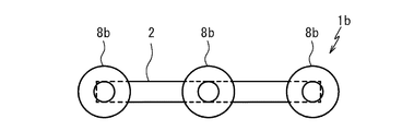
図6及び図7に示す本発明の第三実施形態に係る歪みセンサユニット1bは、長手方向の伸縮を検出する糸状又は帯状の歪みセンサ素子2と、この歪みセンサ素子2の両端部及び中央部の裏面側(一方の面側)に積層され、歪みセンサ素子2よりも平均幅が大きく、少なくとも裏面に粘着性を有する複数の粘着シート3と、歪みセンサ素子2の両端部及び中央部の表面側(他方の面側)を覆うよう粘着シート3に対向して積層される1対の被覆シート8bとを備える。
[Third Embodiment]
The
図6及び図7の歪みセンサユニットにおける歪みセンサ素子2及び粘着シート3の構成は、図1及び図2の歪みセンサユニットにおける歪みセンサ素子2及び粘着シート3の構成と同様とすることができる。このため、図6及び図7の歪みセンサユニットについて、図1及び図2の歪みセンサユニットと同じ構成要素には同じ符号を付して重複する説明を省略する。
The configurations of the
<被覆シート>
被覆シート8bは、平面視で粘着シート3と重なるよう、歪みセンサ素子2の表面側に積層されている。
<Coating sheet>
The
また、被覆シート8bは、導電性を有し、歪みセンサ素子2に電気的に接続されることで、歪みセンサ素子2に測定回路への配線を接続するための端子として用いられる。このため、被覆シート8bの歪みセンサ素子2への接着は、例えば導電性接着剤等が用いられる。
Further, the
被覆シート8bとしては、例えば金属箔、金属メッシュ、カーボンクロス等のシート状部材の他、被覆シート8bに対向するシート状の部分と電気的接続のための構造部分とを有するものを用いることができる。前記シート状の部分と電気的接続のための構造部分とを有するものとしては、図示するように、例えばスナップボタンの雄部材等を挙げることができる。被覆シート8bとしてスナップボタンの雄部材を用いる場合、検出回路の配線の先端にスナップボタンの雌部材を配設することで、歪みセンサ素子2に測定回路への配線が容易となる。
As the
<利点>
当該歪みセンサユニット1bは、歪みセンサ素子2の中央部にも粘着シート3を有することによって、各粘着シート3の間が独立した歪みセンサとして機能する。つまり、当該歪みセンサユニット1bは、測定対象部位の2つの連続する区間の動きを測定することができる。
<Advantage>
The
[その他の実施形態]
前記実施形態は、本発明の構成を限定するものではない。従って、前記実施形態は、本明細書の記載及び技術常識に基づいて前記実施形態各部の構成要素の省略、置換又は追加が可能であり、それらはすべて本発明の範囲に属するものと解釈されるべきである。
[Other Embodiments]
The embodiments do not limit the configuration of the present invention. Therefore, it is possible to omit, replace or add components of each part of the embodiment based on the description of the present specification and common general technical knowledge, and all of them are construed as belonging to the scope of the present invention. Should be.
当該歪みセンサユニットにおいて、粘着シートが粘着剤層のみから形成されてもよい。 In the strain sensor unit, the pressure-sensitive adhesive sheet may be formed only from the pressure-sensitive adhesive layer.
歪みセンサ素子は、粘着シートが積層される部分が粘着シートに対応する形状に拡幅するよう形成されてもよい。 The strain sensor element may be formed so that the portion where the adhesive sheets are laminated is widened to a shape corresponding to the adhesive sheet.
歪みセンサ素子の裏面の粘着シート間に粘着剤が積層されていてもよい。 An adhesive may be laminated between the adhesive sheets on the back surface of the strain sensor element.
当該歪みセンサユニットのリードは、接着部を有しないものであってもよい。 The lead of the strain sensor unit may not have an adhesive portion.
本発明は、人体等の動きを検出するために広く利用することができる。 The present invention can be widely used for detecting the movement of the human body or the like.
1,1a,1b 歪みセンサユニット
2 歪みセンサ素子
3 粘着シート
4 基材層
5 粘着剤層
6 離型シート
7 粘着剤パッチ
8,8b 被覆シート
9 リード
10 接着部
1,1a, 1b
Claims (4)
前記歪みセンサ素子の一方の面の両端部に積層され、前記歪みセンサ素子よりも平均幅が大きく、少なくとも一方の面に粘着性を有する1対の粘着シートと
を備え、
前記粘着シートが基材層とこの基材層の一方の面側に積層される粘着剤層とを有し、
前記歪みセンサ素子の両端部に接続される1対のリードをさらに備え、
前記リードは部分的に拡幅し、拡幅した部分の少なくとも一方の面側に、粘着性を有する接着部を有する歪みセンサユニット。 A thread-like or band-shaped strain sensor element that detects expansion and contraction in the longitudinal direction having elasticity, and
A pair of adhesive sheets that are laminated on both ends of one surface of the strain sensor element, have a larger average width than the strain sensor element, and have adhesiveness on at least one surface are provided.
The pressure-sensitive adhesive sheet have a pressure-sensitive adhesive layer laminated on one surface of the base layer and the substrate layer,
Further provided with a pair of leads connected to both ends of the strain sensor element.
A strain sensor unit in which the lead is partially widened and has an adhesive portion having an adhesive portion on at least one surface side of the widened portion .
Priority Applications (2)
| Application Number | Priority Date | Filing Date | Title |
|---|---|---|---|
| JP2016102879A JP6821949B2 (en) | 2016-05-23 | 2016-05-23 | Distortion sensor unit |
| PCT/JP2017/018491 WO2017204048A1 (en) | 2016-05-23 | 2017-05-17 | Deformation sensor unit and deformation measurement kit |
Applications Claiming Priority (1)
| Application Number | Priority Date | Filing Date | Title |
|---|---|---|---|
| JP2016102879A JP6821949B2 (en) | 2016-05-23 | 2016-05-23 | Distortion sensor unit |
Publications (3)
| Publication Number | Publication Date |
|---|---|
| JP2017211215A JP2017211215A (en) | 2017-11-30 |
| JP2017211215A5 JP2017211215A5 (en) | 2019-06-06 |
| JP6821949B2 true JP6821949B2 (en) | 2021-01-27 |
Family
ID=60411277
Family Applications (1)
| Application Number | Title | Priority Date | Filing Date |
|---|---|---|---|
| JP2016102879A Active JP6821949B2 (en) | 2016-05-23 | 2016-05-23 | Distortion sensor unit |
Country Status (2)
| Country | Link |
|---|---|
| JP (1) | JP6821949B2 (en) |
| WO (1) | WO2017204048A1 (en) |
Families Citing this family (2)
| Publication number | Priority date | Publication date | Assignee | Title |
|---|---|---|---|---|
| JP7389958B2 (en) * | 2019-03-20 | 2023-12-01 | 大日本印刷株式会社 | Wiring board and wiring board manufacturing method |
| JP2021056315A (en) * | 2019-09-27 | 2021-04-08 | ヤマハ株式会社 | Keyboard device |
Family Cites Families (4)
| Publication number | Priority date | Publication date | Assignee | Title |
|---|---|---|---|---|
| US4141366A (en) * | 1977-11-18 | 1979-02-27 | Medtronic, Inc. | Lead connector for tape electrode |
| JPS6441803A (en) * | 1987-08-10 | 1989-02-14 | Kazuo Tsuchiya | Apparatus for measuring angle and displacement quantity using electric resistor piece |
| JP2011032449A (en) * | 2009-07-29 | 2011-02-17 | Dengiken:Kk | Adhesive tape and solar cell module using the same |
| JP6536006B2 (en) * | 2014-10-17 | 2019-07-03 | ヤマハ株式会社 | Strain sensor fixing method |
-
2016
- 2016-05-23 JP JP2016102879A patent/JP6821949B2/en active Active
-
2017
- 2017-05-17 WO PCT/JP2017/018491 patent/WO2017204048A1/en active Application Filing
Also Published As
| Publication number | Publication date |
|---|---|
| WO2017204048A1 (en) | 2017-11-30 |
| JP2017211215A (en) | 2017-11-30 |
Similar Documents
| Publication | Publication Date | Title |
|---|---|---|
| JP6014906B2 (en) | Strain sensor | |
| US11175124B2 (en) | Strain sensor unit | |
| JP5924725B2 (en) | Strain sensor and method for manufacturing strain sensor | |
| US10966316B2 (en) | Wiring film, device transfer sheet, and textile type device | |
| JP6264825B2 (en) | Fabric and clothing with strain sensor | |
| JP2017075847A (en) | Movement detection device | |
| JP6536006B2 (en) | Strain sensor fixing method | |
| JP6821949B2 (en) | Distortion sensor unit | |
| JP6488698B2 (en) | External force detection array module | |
| FI128364B (en) | A sensor with a connection to a stretchable wiring | |
| JP2014160041A (en) | Strain sensor and method for manufacturing the same | |
| JP2017009559A (en) | Distortion sensor element | |
| JP6561636B2 (en) | Strain sensor element | |
| JP2016080520A (en) | Strain sensor | |
| JP7388412B2 (en) | Strain sensor element manufacturing method and strain sensor element | |
| JP6848458B2 (en) | Sensor unit | |
| JP6561640B2 (en) | Strain sensor element | |
| JP7159038B2 (en) | Swallowing motion measuring method and swallowing motion measuring device | |
| JP2017211214A (en) | Strain sensor and strain sensor unit | |
| JP2020173169A (en) | Circumference measuring device and capacitance type sensor element | |
| JP2016176874A (en) | Strain sensor element | |
| JP2016176875A (en) | Strain sensor and electrode | |
| JP7467828B2 (en) | Strain sensor unit and extension amount measuring member | |
| WO2020111073A1 (en) | Sensor body and sensor devie | |
| JP2019086522A (en) | Strain sensing module |
Legal Events
| Date | Code | Title | Description |
|---|---|---|---|
| A621 | Written request for application examination |
Free format text: JAPANESE INTERMEDIATE CODE: A621 Effective date: 20190411 |
|
| A521 | Request for written amendment filed |
Free format text: JAPANESE INTERMEDIATE CODE: A523 Effective date: 20190424 |
|
| A131 | Notification of reasons for refusal |
Free format text: JAPANESE INTERMEDIATE CODE: A131 Effective date: 20200526 |
|
| A521 | Request for written amendment filed |
Free format text: JAPANESE INTERMEDIATE CODE: A523 Effective date: 20200722 |
|
| TRDD | Decision of grant or rejection written | ||
| A01 | Written decision to grant a patent or to grant a registration (utility model) |
Free format text: JAPANESE INTERMEDIATE CODE: A01 Effective date: 20201208 |
|
| A61 | First payment of annual fees (during grant procedure) |
Free format text: JAPANESE INTERMEDIATE CODE: A61 Effective date: 20201221 |
|
| R151 | Written notification of patent or utility model registration |
Ref document number: 6821949 Country of ref document: JP Free format text: JAPANESE INTERMEDIATE CODE: R151 |